Embed Size (px)
Citation preview
Technical report, IDE0612, January 2006
ZigBee suitability for Wireless Sensor Networks in Logistic Telemetry Applications
Master’s Thesis in Computer Systems Engineering
submitted by
Kamran Javed
School of Information Science, Computer and Electrical Engineering Halmstad University

ZigBee suitability for Wireless Sensor Networks in Logistic Telemetry Applications
Master’s thesis in Computer Systems Engineering
School of Information Science, Computer and Electrical Engineering Halmstad University
Box 823, S-301 18 Halmstad, Sweden
January 2006


i
Acknowledgements I would like to thank Supervisor Markus Adolfsson for his support, guidance and ideas during the writing of this thesis. I would also like to thank XCube Communications which provided me an excellent opportunity to do the research in a respective area of looking at the suitability of ZigBee in WSN in logistic telemetry Application. I would like also to thank all those people including family and friends who contributed in any way to help me during this thesis. Special thanks to all the members of my family, especially my father and mother. Kamran Javed

ii

iii
Abstract There has been a quick development in the wireless network area during the last decade. Mostly these days the focus in the wireless area is on very high speed and long range applications. This thesis describes how ZigBee is suitable for wireless sensor networks in logistic telemetry applications for global managing and monitoring of goods. ZigBee has been developed by the organization named as ‘ZigBee Alliance’ as a new wireless standard for the wireless solutions based upon the IEEE 802.15.4 Standard [2]. ZigBee is a new technology as compared to the other wireless technologies such as Bluetooth, but it has certain characteristics such as low cost, low power, support for mesh networking e.t.c which makes its chances to be more successful than others. The other aim of this thesis is to examine different issues related to ZigBee to see its fitness for logistic telemetry applications like multi-hop routing issues, routing strategies and design requirements. ZigBee is relatively new wireless technology, so there are great deals of promises associated with it. In this thesis, a comparison between ZigBee and Bluetooth technologies will also be made.

iv
v
Contents
ACKNOWLEDGEMENTS..........................................................................................................................................I
ABSTRACT................................................................................................................................................................III
CONTENTS................................................................................................................................................................. V
ABBREVIATIONS .................................................................................................................................................. VII
1 INTRODUCTION .............................................................................................................................................. 1
1.1 XCUBE COMMUNICATION INC. .................................................................................................................... 2 1.1.1 XCube SEAL™ System Overview........................................................................................................... 2
1.2 PROBLEM DEFINITION.................................................................................................................................. 4 1.3 THESIS GOAL ............................................................................................................................................... 4 1.4 RELATED WORK .......................................................................................................................................... 5
2 THEORETICAL BACKGROUND .................................................................................................................. 6
2.1 TELEMATICS ................................................................................................................................................ 6 2.2 WIRELESS SENSOR NETWORK...................................................................................................................... 6 2.3 IEEE 802.15.4 STANDARD OVERVIEW ........................................................................................................ 7 2.4 ZIGBEE OVERVIEW ...................................................................................................................................... 8 2.4.1 TECHNOLOGY.............................................................................................................................................. 9 2.4.2 PROTOCOL STACK SYSTEM........................................................................................................................ 11
2.4.2.1 Overview of Different Layers........................................................................................................... 12 2.4.2.2 Physical Layer ................................................................................................................................. 12 2.4.2.3 MAC Layer ...................................................................................................................................... 15 2.4.2.4 Network Layer ................................................................................................................................. 16 2.4.2.5 Application layer ............................................................................................................................. 17
2.5 NETWORK TOPOLOGY................................................................................................................................ 17 2.5.1 PAN (Personal Area Network) Coordinator ........................................................................................ 19 2.5.2 Full Function Device............................................................................................................................ 19 2.5.3 Reduced Function Device..................................................................................................................... 19
2.6 ROUTING PROTOCOLS AND ALGORITHMS USED IN ZIGBEE WSN .............................................................. 20 2.6.1 AODV: Ad-hoc On Demand Distance Vector ...................................................................................... 20 2.6.2 Cluster Tree Algorithm......................................................................................................................... 22 2.6.3 Message routing ................................................................................................................................... 24 2.6.4 Neighbour routing ................................................................................................................................ 24
2.7 ZIGBEE: LOW POWER, LOW COST, LOW DATA RATE TECHNOLOGY............................................................ 24 2.8 LOGISTIC TELEMETRY APPLICATIONS......................................................................................................... 26 2.9 SYSTEM DESIGNS IN LOGISTIC ENVIRONMENTS.......................................................................................... 28
2.9.1 Design of systems in ships .................................................................................................................... 28 2.9.2 Design of systems in Airplanes............................................................................................................. 29 2.9.3 Design of systems in Trucks ................................................................................................................. 30
2.10 WORKING OF EXISTING TECHNOLOGY....................................................................................................... 31 2.10.1 General overview of the RFID systems and the working inside container ...................................... 32 2.10.2 Communication to outside the container ......................................................................................... 33
3 ZIGBEE SUITABILITY IN WSN IN LOGISTIC TELEMETRY APP LICATIONS............................... 34
(METHODOLOGY AND ANALYSIS) ................................................................................................................... 34
3.1 POSSIBLE SUITABLE ZIGBEE NETWORK DESIGN........................................................................................ 34
vi
3.1.1 Single hop communication in case of ZigBee Sensor Network............................................................. 36 3.1.2 ZigBee Support for Multi hop communication ..................................................................................... 36
3.2 ZIGBEE MULTI-HOP MESH NETWORK IN WIRELESS SENSOR NETWORKS.................................................. 38 3.3 ZIGBEE IN RELOADING SITUATIONS .......................................................................................................... 39 3.4 ANALYSIS .................................................................................................................................................. 41 3.4.1 LOW POWER, LOW COST AND LOW DATA RATE........................................................................................... 41 3.4.2 ROUTING PROTOCOLS................................................................................................................................ 42 3.4.3 SYNCHRONIZATION.................................................................................................................................... 44 3.5 COMPARISON AMONG DIFFERENT WIRELESS TECHNOLOGIES.................................................................... 45
4 DISCUSSION.................................................................................................................................................... 47
5 FUTURE WORK..............................................................................................................................................48
6 CONCLUSION ................................................................................................................................................. 49
7 REFERENCES ................................................................................................................................................. 50
vii
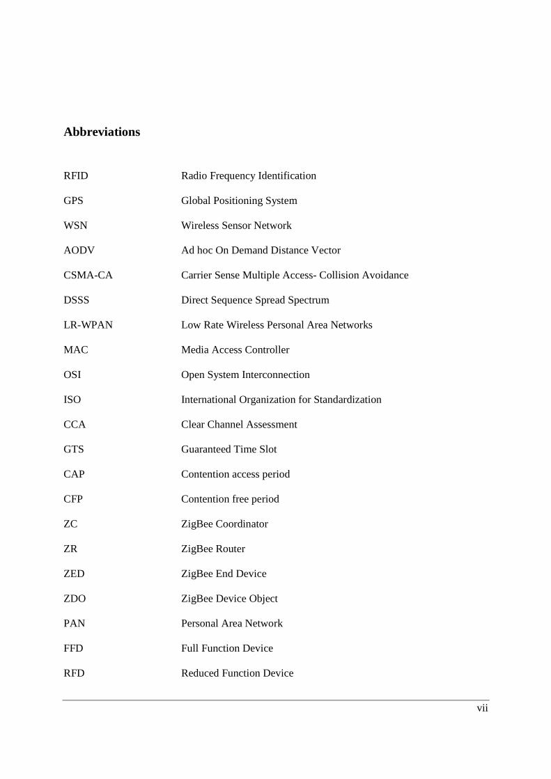
Abbreviations
RFID Radio Frequency Identification GPS Global Positioning System WSN Wireless Sensor Network AODV Ad hoc On Demand Distance Vector CSMA-CA Carrier Sense Multiple Access- Collision Avoidance DSSS Direct Sequence Spread Spectrum LR-WPAN Low Rate Wireless Personal Area Networks MAC Media Access Controller OSI Open System Interconnection ISO International Organization for Standardization CCA Clear Channel Assessment GTS Guaranteed Time Slot CAP Contention access period CFP Contention free period ZC ZigBee Coordinator ZR ZigBee Router ZED ZigBee End Device ZDO ZigBee Device Object PAN Personal Area Network FFD Full Function Device RFD Reduced Function Device

viii
RREQ Route Request RREP Route Reply DD Designated Device GSM Global System for Mobile Communication SCE Satellite Communication Equipment TDMA Time Division Multiple Access FHSS Frequency Hopping Spread Spectrum
Introduction
1
1 Introduction Wireless technology is becoming more popular as it overcomes the disadvantage of having the user restricted in a particular location. Wireless communication systems constitute a solution that can be deployed easily, decreasing the overall cost of the system. [1] A great deal of work has been done in the field of Wireless technologies in the last era, thus we also need to use these wireless technologies in logistic applications in which one has to track the items in different states. It can be a static state in which the items are just in the same state for a long period of time or can be dynamic (for example, in reloading situations) where the items move to dynamic state for a short period of time before returning to the static state. In these kinds of situations, it has to be considered how energy can be conserved during the different phases or states in the logistic telemetry situations. There are different design issues which need to be considered while using the ZigBee in telemetry situations. ZigBee can be more effective in the reloading phase or in the tracking of the different kinds of the items (which can be the vehicles or different pallets in the container) which have to be monitored in order to ensure that there is no damage or the loss of any item, while transferred from one location to another. This thesis shows that ZigBee can be more convenient in logistic telemetry situations and different ways in which it can be more effective than the other wireless technologies of its own kind. It will also study different multi-hop issues related to routing and the kind of routing strategies that are available. The study will also cover the involvement of ZigBee in the reloading situations of the items when the items are transferred from complete static situation to the complete dynamic situation. In the first part of this thesis, the ZigBee technology will be discussed in detail so that the common reader can have an overview of this Technology. Moreover, logistic telemetry applications will be studied. Then the way ZigBee can be fitted into these kinds of logistic telemetry situations will be examined. This Thesis is carried out in corporation with XCube Communication Inc., which wants to evaluate the suitability of ZigBee in logistics telemetry applications.

Introduction
2
1.1 XCube Communication Inc. XCube Communication Inc. situated in Gothenberg, Sweden was established to do business in telematics system solutions area by using industrial and technological knowledge. The goal of the company is to provide worldwide tracking of the goods when transferring in any environment like sea, air and land. XCube Communication provides a system that enables the customer to use the gathered information from the items or goods that are transferred from one place to another (More Information is available on company’s website www.x3-c.com ). [3]
1.1.1 XCube SEAL™ System Overview
The XCube system which is named SEAL™ system is derived from sea-air-land. XCube Communication SEAL™ answers a lot of questions, which the customers have in their minds about the transferring and safety of their goods [3].
Figure1: Describing the XCube SEAL™ Technology
SEAL™ system actually consists of SEAL™ ARFID (Active RFID) Tags (see section 2.5.2), Field Client and SEAL™ Portal servers. The ARFID with the support of the GPS (Global Positioning System) delivers the data like temperature, acceleration, humidity e.t.c. continuously to the central system. Figure 1 shows that there are pallets in a container and on each container there is SEAL™ ARFID tags which send the information to the SEAL™ field client on the container, from where the data is finally sent to the SEAL™ portal on the client side.
Introduction
3
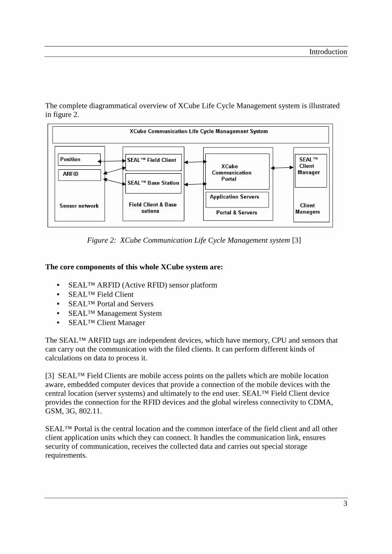
The complete diagrammatical overview of XCube Life Cycle Management system is illustrated in figure 2.
Figure 2: XCube Communication Life Cycle Management system [3]
The core components of this whole XCube system are:
• SEAL™ ARFID (Active RFID) sensor platform • SEAL™ Field Client • SEAL™ Portal and Servers • SEAL™ Management System • SEAL™ Client Manager
The SEAL™ ARFID tags are independent devices, which have memory, CPU and sensors that can carry out the communication with the filed clients. It can perform different kinds of calculations on data to process it. [3] SEAL™ Field Clients are mobile access points on the pallets which are mobile location aware, embedded computer devices that provide a connection of the mobile devices with the central location (server systems) and ultimately to the end user. SEAL™ Field Client device provides the connection for the RFID devices and the global wireless connectivity to CDMA, GSM, 3G, 802.11. SEAL™ Portal is the central location and the common interface of the field client and all other client application units which they can connect. It handles the communication link, ensures security of communication, receives the collected data and carries out special storage requirements.
Introduction
4
SEAL™ Management System is to carry out operation more efficiently and the maintenance more easily. Some of its tasks are: management of the applied system and different levels of user authentication but it does not provide application services. Devices distributed globally are managed by the services provided by this system. SEAL™ Client Manager provides the real user interface to the system which addresses the management of the transports that involve the sensor devices and the field client. It comprised tools for managing the SEAL™ Field Clients, SEAL™ ARFID devices and others. Its main task is to take care of managing different functions or tasks needed to be done during the shipments efficiently. [3]
1.2 Problem Definition The problem here can be specified as:
• ZigBee is a fast emerging wireless technology. The problem is to find out how a low cost, low data rate wireless technology like ZigBee can be appropriate or suitable for the wireless sensor networks in logistic telemetry applications.
• Which factors of ZigBee can be used in these situations and the trade offs related to them?
• What is the possible design of the WSN inside the container carrying the goods?
• How the mesh networking will be carried out in the WSN created by ZigBee?
• What are the different multi-hop routing protocols which can be used to carry out the
routing between the nodes?
1.3 Thesis Goal
• The goal of the thesis is to examine and explore the possibility of making ZigBee a suitable technology in the logistic telemetry applications.
• The aim is to study all those factors concerning the technology of ZigBee, design issues,
routing strategies which will make this technology applicable in these logistic telemetry situations.
Introduction
5
• To see the working of mesh networking supported by ZigBee.
• Analysis of the routing strategies used to take care of the routing which in our case will be Ad hoc On Demand Distance Vector (AODV) and Cluster-Tree algorithm.
1.4 Related Work A great deal of work has been done by using wireless sensor networks in the tracking of goods in the telemetry applications. Some other wireless protocols have been used providing tracking from time to time. In tracking, it is important to know the exact location and place of the moving target to measure the different attributes associated with the target item. Currently the RFID is one of the technologies that are used for the tracking of items in the logistic applications. The sensors and RFID tags are attached to the devices from which the exact location and condition of device can be obtained. There are great numbers of companies proving the tracking solutions in logistic telemetry applications; one of them is XCube Communication which used RFID technology for providing tracking solution described in [3]. [15] Describes the communication carried through RFID from the inside of the container to the outside world. ZigBee is quite a new technology in the field of tracking and it is currently under research to see its suitability for WSN. [2] Describes in detail how ZigBee can work in the wireless networking and gives a method how to examine different attributes (attached to the items) like temperature. This work is quite important help to design the system of ZigBee sensor network in this thesis. This debate focuses on ZigBee features and the benefits that it can offer in tracking of goods. One wants to know the situation of his goods at different phases of transfer while sitting at any place.
Theoretical Background
6
2 Theoretical Background
This section presents the background material to this thesis. The ZigBee technology and logistic situations will be discussed thoroughly. The ZigBee is based on the IEEE 802.15.4 standard which gives the specifications of the Physical and MAC layers.
2.1 Telematics Telematics refer to the exchange of information or communication between different sources [21] through the wireless means. Telemetry, which is used for monitoring and control applications, is closely attached to the telematics. Telemetry applications are used with vehicle concerning applications. Based on the Global Positioning System (GPS) and cellular phone technology, different telematics applications have been designed. Some other applications of the telematics in the real world are asset tracking and fleet management system.
2.2 Wireless Sensor Network In the last decade [9], there has been a lot of research done in the wireless area all over the world. First of all, a sensor network is a kind of network that is made up of a large number of sensor nodes. These nodes are spread to carry out different kinds of operations to find the values of different kinds of attributes like temperature, acceleration, humidity etc. in certain environments. So there is no need to have a big computer setup to evaluate all these things, instead cheap small sensor devices. One of the good uses of these wireless sensor networks is in the logistic telemetry applications in which one wants to know the condition of goods during transfer and to know the condition of different attributes associated with the goods. There are four different components of the sensor node [10]; namely sensing, power, transceiver and processing units; moreover there are some more components in a sensor node like location finding system, power generator and mobilizer. WSNs give a kind of ways in the physical world to solve some problems which were not available before evolution of WSNs. Some of the important features which are important to know concerning the understanding of the wireless sensor networks are [9] [10]:
• Due to the small battery requirements, it is important for a sensor node to conserve energy to stay alive for a longer period of time. That’s why it goes to sleeping mode some times during operation to conserve energy.
• Communicating nodes are attached to each other by some wireless medium in the multi-
hop sensor networks, so the medium which will be used should be available worldwide.

Theoretical Background
7
• Encryption methods can be used to carry out the security operations in these networks
• Physical layer in the sensor network protocol stack is responsible for the detection of
signals, modulation and generating carrier frequency.
• Compared to the networks, build up using wires, it requires less maintenance for the wireless sensor networks.
• These networks are easy to install and if some configuration needs to be done, it is also
easy to carry out. These networks consist of cost effective sensor nodes which can be replaced by new nodes if they experience some problem.
Looking at the above mentioned characteristics of wireless sensor networks, it has to be observed how ZigBee can fit to these wireless sensor networks in some specific logistic situations.
2.3 IEEE 802.15.4 Standard Overview This standard uses radio communication in the personal area networks (PAN) to carry out the communication between the devices and also define protocols for establishing connection between them. [7] It uses channel access mechanisms like Slotted CSMA/CA which helps avoid the collisions. PAN coordinator can reserve time slots for the devices using the super frame structure at the media access layer. This standard deals with two PHYs, one is 868/915 MHz PHY and the other is 2450 MHz PHY, both use the direct sequence spread spectrum (DSSS) modulation scheme. The data rates supported are 20 kb/s and 40 kb/s (for 868/915 MHz PHY) and 250 kb/s for 2450 MHz PHY. [7] This low rate wireless personal area networks (IEEE 802.15.4/ LR-WPAN) standard will provide the solutions for different applications at low power and low cost. This standard describes the two lower layers Physical and MAC of the ZigBee Stack described in section 2.3.2. Key features of these layers are given in sections 2.3.2.2 and 2.3.2.2 respectively. The WPAN consists of three devices which are PAN coordinator, FFD and RFD described in detail in section 2.3.3. The topologies supported by this standard used by ZigBee are star, mesh and cluster tree topologies, which are described in section 2.3.3. [19]
Theoretical Background
8
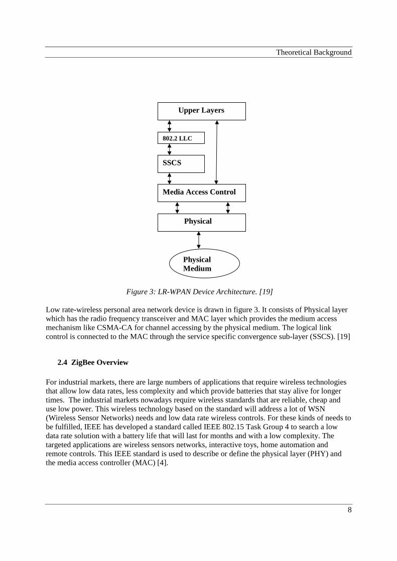
Figure 3: LR-WPAN Device Architecture. [19] Low rate-wireless personal area network device is drawn in figure 3. It consists of Physical layer which has the radio frequency transceiver and MAC layer which provides the medium access mechanism like CSMA-CA for channel accessing by the physical medium. The logical link control is connected to the MAC through the service specific convergence sub-layer (SSCS). [19]
2.4 ZigBee Overview For industrial markets, there are large numbers of applications that require wireless technologies that allow low data rates, less complexity and which provide batteries that stay alive for longer times. The industrial markets nowadays require wireless standards that are reliable, cheap and use low power. This wireless technology based on the standard will address a lot of WSN (Wireless Sensor Networks) needs and low data rate wireless controls. For these kinds of needs to be fulfilled, IEEE has developed a standard called IEEE 802.15 Task Group 4 to search a low data rate solution with a battery life that will last for months and with a low complexity. The targeted applications are wireless sensors networks, interactive toys, home automation and remote controls. This IEEE standard is used to describe or define the physical layer (PHY) and the media access controller (MAC) [4].
Upper Layers
Media Access Control
Physical
802.2 LLC
SSCS
Physical Medium
Theoretical Background
9
ZigBee technology defines some of the layers like network, security, and application framework profile for a system based on IEEE 802.15.4 standard. The IEEE standard at the PHY is very important for defining the architecture of the RF and the ZigBee topology. Network/Security Layers are the important layers above the physical and MAC layers for control and sensor integration. For topologies like star, mesh and cluster tree, ZigBee will define the overall properties of these layers of ZigBee stack described in section 2.3.2. These networks will follow the IEEE 802.15.4 standard to carry out the functions [4]. ZigBee can be divided into the following three segments which cover all its issues.
(i) Technology (ii) Protocol Stack System
(iii) Network Topology
2.4.1 Technology Describing the technology of the ZigBee is very important for the common reader to understand what are the factors or features which make up this technology. ZigBee will define the layers (network, security, and application framework profile layers) above the PHY and MAC layers. In the future, ZigBee will be a standard which will be used globally for the sensor and control applications. ZigBee Technology can be best described by discussing the following points [5] [6]: Low cost ZigBee is a low cost technology, which means the cost of the device, its installation and maintenance are low and the batteries using primary cells can stay alive for months. Greater Number of Nodes per Network As ZigBee uses the IEEE 802.15.4 which defines PHY and MAC layers, so it allows to use any number of nodes or devices (important for the larger control networks and larger arrays of sensors). Very Low power consumption and simple implementation The batteries can be used for months or years because of the low power consumption depending on the duty cycle involved. Simplicity of protocol and global implementation It is estimated that the ZigBee protocol code stack is about one fourth compared to Bluetooth. It is just this simplicity which adds to the low cost and the maintenance. ZigBee is using the IEEE 802.15.4 PHY, which is operating at different frequency bands including 915 MHz for Australia,
Theoretical Background
10
N America, and for Europe it is using 868 MHz band and 2.4 GHz band globally for almost all countries worldwide. Use two different states ZigBee uses two different kinds of states to run the operation i.e. the active (in which sending and receiving can be performed) and the sleep states to conserve energy and power. Low Duty Cycle Duty cycle is very important to be considered. In case of ZigBee, it is less than 0.1 percent which is extremely low. Depending on the requirements of application it can be increased or decreased. Dual PHY Frequency bands used on PHY can be 868/915 MHz and 2.4GHz. Data rates supported on 868 MHz, 915 MHz and 2.4 GHz are 20 kbps, 40 kbps and 250 kbps respectively. Channel Access Mechanism Channel Access mechanism used here is CSMA-CA which results in greater throughput for controls and sensors applications. Hand-Shaked protocol ZigBee provides a fully handshake protocol which ensures that the transfer of data is reliable. Capable Address Space Address space is provided for up to 18,450,000,000,000,000,000 devices using 64 bit IEEE address where about 65,535 networks can be supported (per network there can be 255 devices). Optional Guaranteed Time Slot An optional guaranteed time slot is available in case of some failure or need. Range The range covered is typically about 10m and about 1-100m which is based on the settings of the surrounding environment. Traffic Types ZigBee has the following three traffic types:
• Periodic data: in this type of traffic type the data rate is defined by the application and the sensors are the example of this type of scenario.
• Intermittent data: This traffic type uses the data defined externally by some stimulus or
by the application. E.g. light switch.
Theoretical Background
11
• Repetitive low latency data: Here the time slots are allocated, for example see the
scenario in case of mouse.
IEEE802.15.4 MAC is able to deal with all these three types of traffic. By its beaconing mechanism, it can deal with the periodic data in which sensors wake up, look for the messages and go back to the sleep mode. It can handle the intermittent data by the beaconless system or in a disconnected way in which device connects to the network only when it wants to communicate to other devices to carry out some operation. Low latency data rate applications will be given the optional guaranteed time slot. Topologies ZigBee supports different kinds of topologies like star, peer-to-peer and mesh topologies, which add to the properties of the network and how the data will be transferred or how the communication carried out. Topologies will be further discussed in section 2.3.3 where it will be shown how topology works in case of ZigBee.
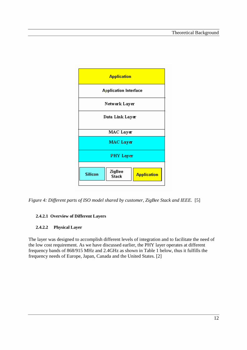
2.4.2 Protocol Stack System We know that the OSI (Open System Interconnection) model was developed for the protocol architecture and a platform for making protocols standards by the International Organization for Standardization (ISO). Each layer in OSI model has a specific function to perform starting from the Physical layer up to Application layer. The top layers networking, security, and applications which have not been defined by the IEEE, are defined by the ZigBee (ZigBee Alliance). It is very important to consider the working of different layers and the interaction of the ZigBee protocol stack. The portion under the upper MAC layer including the lower MAC layer and the PHY layer (Silicon) has been defined by IEEE. Figure 4 describes the ZigBee stack. [1] [5]
Theoretical Background
12
Figure 4: Different parts of ISO model shared by customer, ZigBee Stack and IEEE. [5]
2.4.2.1 Overview of Different Layers
2.4.2.2 Physical Layer
The layer was designed to accomplish different levels of integration and to facilitate the need of the low cost requirement. As we have discussed earlier, the PHY layer operates at different frequency bands of 868/915 MHz and 2.4GHz as shown in Table 1 below, thus it fulfills the frequency needs of Europe, Japan, Canada and the United States. [2]

Theoretical Background
13
Table 1: Frequency Bands and Data Rates [7]
There are two types of modulations used with different frequency bands. O-QPSK is the modulation technique used with the frequency band of 2.4 GHz supported by 2MHz RF bandwidth. With the other frequency bands, the modulation scheme used is BPSK with bandwidth for RF provided as 1200 kHz in North America and 600 kHz for Europe. DSSS (Direct Sequence Spread Spectrum) mechanism is used by both pairs of PHY operating at different frequencies. [2] In the PHY layer, the mechanism of converting the binary data to a modulated signal can be described as follows: [7] Firstly, the binary data in the PHY Protocol Data Unit (PPDU) is transformed from bits to symbols. Two symbols result from every byte by transferring the least significant symbol. Secondly, 32 Chip Sequence results from each symbol and then this sequence using 2 MChip/s transmitted rate is transmitted by transferring the least significant chip first. Here the half sine shift is done by using the Offset – Quadrature Phase Shift Keying (O-QPSK) to obtain the modulated signal, which some times uses the limited bandwidth. The phase shift remains under 90 degrees and does not try to pass this value. O-QPSK can be expressed by the following equation.
[7]
Theoretical Background
14
Where Tc is the time and fc is the center frequency to obtain the 90 degrees shift in the phase by delaying the Q. Some basic functions of PHY are energy detection(ED), link quality indication (LQI), channel selection, clear channel assessment (CCA) described below [19]. Receiver Energy Detection (ED) The network layer uses this ED measurement to select the specific algorithm for channel accessing like CSMA/CA. This is the estimated combined value of the IEEE 802.15.4 bandwidth specified for the channel and the power of the received signal. The estimated time for the ED is approximately 8 symbols [19]. Link Quality Indication (LQI) The LQI indicates and measures how good are the quality and the value of the received packet. Receiver ED can be used to measure the LQI or we can use the signal to noise value [19]. Clear Channel Assessment (CCA) The CCA is for the channel accessing for CSMA/CA. CCA method can be done in any of the following three ways [19].
• Energy above threshold. Here the CCA is used to measure the energy value, if energy is above the ED threshold, then it will report that the medium is busy.
• Carrier sense only. Here the energy level of the signal can be more or less than the ED
threshold but CCA reports a busy medium only in case if the signal is having the modulation properties of the standard IEEE 802.15.4.
• Carrier sense with energy above threshold. In this case the CCA reports that the
medium is busy in case the energy is more than ED threshold and the signal has the modulation properties of the standard IEEE 802.15.4.

Theoretical Background
15
2.4.2.3 MAC Layer
Media Access Control (MAC) has different responsibilities [7]:
• The main function of MAC is to carry out the association and disassociation of the network involved. A large number of devices are managed or handled by this layer.
• It generates the network beacons according to the device, if it is a coordinator • It also performs the function of synchronizing the beacons. • It uses the CSMA-CA channel access mechanism • It uses Guaranteed Time Slot (GTS) mechanism. • It allows different mechanisms to conserve energy like collision avoidance using CSMA-
CA and allowing the device to go into sleep mode. There are different types of MAC frames
• Beacon Frame • Data Frame • Acknowledgement Frame • Mac Command Frame
General MAC Frame format is given in table 2: [7]
Table2: General MAC Frame Format The interaction between the SSCS and the PHY layer is provided by the MAC sub layer consisting of MLME (a management entity) which provides some services to carry out the management functions and also maintains the database of objects related to MLME. Two services
Theoretical Background
16
called Data and Management services provide interface between SSCS, and the PHY is provided by MAC sub layer. [7] Super frame is used in the LR-WPAN, which is divided into 16 slots and the first slot contains the beacon frame. The beacons, which surround the super frame, specify its structure and the PAN. There are active and in active portions in the super frame. Contention access period (CAP) and contention free period (CFP) are parts of the active portion. The devices compete with each other using CSMA-CA to carry out the communication. The end portion of the super frame contains the GTS (Guaranteed Time Slot). The super frame structure and details are given in [19] the algorithms used with the super frame structure is the slotted CSMA-CA (see algorithm details in [19]) which uses the back-off algorithm. [19] There can be three kinds of data transfer techniques which can be used; i.e. firstly from coordinator to a device, secondly from device to a coordinator and thirdly, between two devices. The selection of transfer type depends on the type of the network, which can support beacons and is named as ‘beacon enabled’; otherwise ‘non beacon enabled’. In a non beacon enabled network, only the data frame is transmitted and the CSMA-CA algorithm is used. In the beacon enabled network, the network has to wait for the beacon to arrive, after which it synchronizes the super frame structure and then the data frame is sent. So the synchronization can be of two types; beacon enabled and non-beacon enabled. If one network wants to communicates with another and both are allotted the channel (suppose A), then there can occur problem of sharing the same slot, which can be solved by synchronizing both networks. For details of the following points see [19]. Their understanding is very important.
• Data transfer model • Maintenance of PAN • Beacon generation • Association and Disassociation • Synchronization • Transmission, Reception and Acknowledgement • GTS Allocation and Management • MAC Frame Formats
2.4.2.4 Network Layer
Some of the basic functions of the Network layer can be summarized as follows: [6] [8]
• This layer has been designed to enable the embedded networking at low cost and at low power. Low power radio facilitates the battery to stay for longer time duration.

Theoretical Background
17
• It allows, without the need of high power transmitters the network to grow in size and suffer quite low latencies to handle different number of nodes.
• It has been built based on the IEEE 802.15.4 MAC's features which play an important role
in the extension of the network.
• Different design tradeoffs and some technical requirements are supported by the network layer.
• All the issues regarding routing and network management are also addressed by this layer.
Network structure may look differently depending upon the type of the topology used. Different kinds of routing algorithms are supported by the layer described in section 2.3.4.
• Basic frame handling and device management are also performed on this layer.
• It carries out the address allocation and routing through messages and it provides security
throughout network. • The layer has 3 different types of devices; ZC (ZigBee Coordinator), ZR (ZigBee Router)
and ZED (ZigBee End Device) • It allows the ZigBee routers and other devices to sleep to do the routing at low power, and
allows the recovery of the network from the power failures occurring at certain times.
2.4.2.5 Application layer
Application sub layer, ZigBee Device Object (ZDO) and the objects defined by the manufacturer of an application are those, which ZigBee application layer is comprised of. Application sub layer manages the binding tables which bind two devices on the basis of the needs and services. It also manages the discovery which defines the responsibility of the ZDO (ZigBee Device Object) to take care of the roles of the devices in the network and to develop a reliable connection between the devices. The manufacturer defined objects use the application descriptions given by the ZigBee to make the application. [6]
2.5 Network Topology
The network layer supports different kinds of topologies which enable different kinds of functions and properties. Topologies which can work on this ZigBee Network layer are Star, cluster tree and mesh. There is no need to go into the detail of the topologies but it is important to discuss their function. Mesh network provides a scalable architecture by allowing more than one path, but star network is more commonly used topology used for carrying the battery operations.
Theoretical Background
18
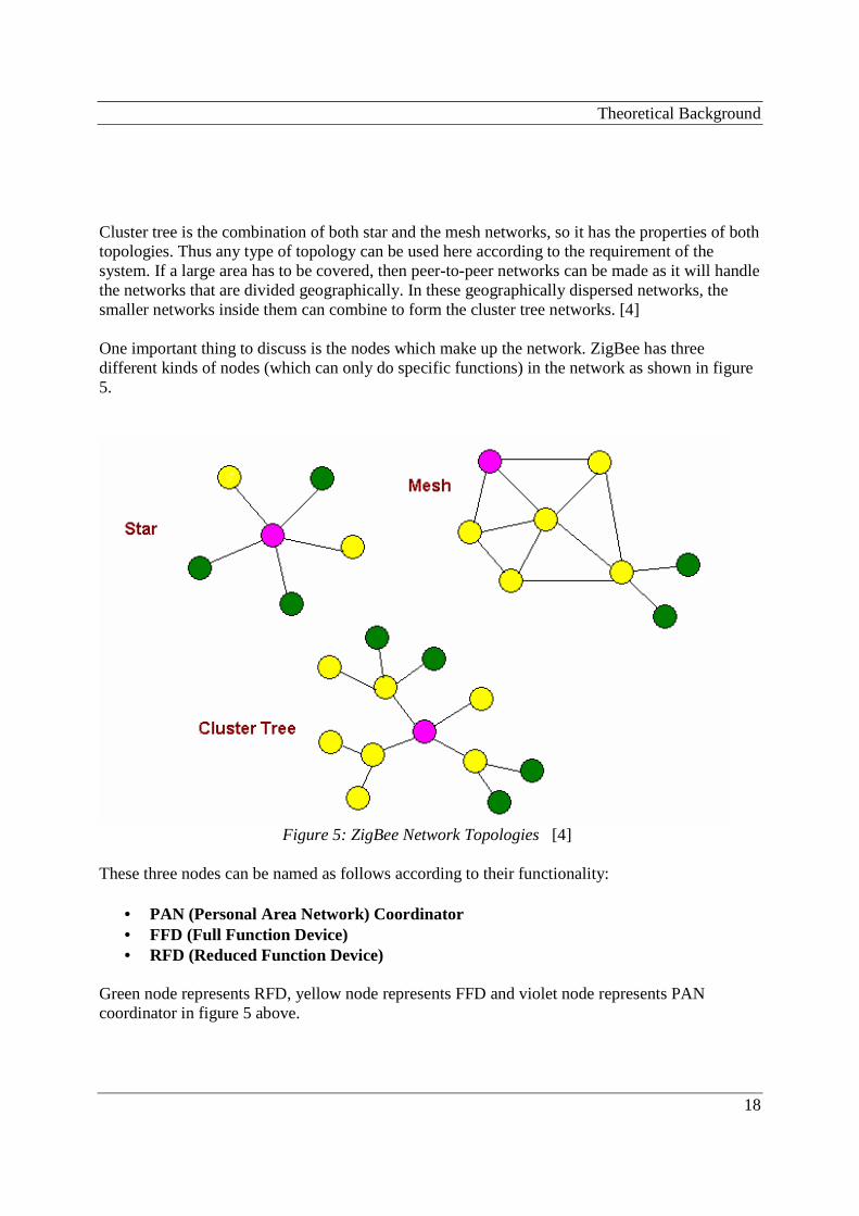
Cluster tree is the combination of both star and the mesh networks, so it has the properties of both topologies. Thus any type of topology can be used here according to the requirement of the system. If a large area has to be covered, then peer-to-peer networks can be made as it will handle the networks that are divided geographically. In these geographically dispersed networks, the smaller networks inside them can combine to form the cluster tree networks. [4] One important thing to discuss is the nodes which make up the network. ZigBee has three different kinds of nodes (which can only do specific functions) in the network as shown in figure 5.
Figure 5: ZigBee Network Topologies [4]
These three nodes can be named as follows according to their functionality:
• PAN (Personal Area Network) Coordinator • FFD (Full Function Device) • RFD (Reduced Function Device)
Green node represents RFD, yellow node represents FFD and violet node represents PAN coordinator in figure 5 above.
Theoretical Background
19
2.5.1 PAN (Personal Area Network) Coordinator
PAN coordinator is the one which initializes the network, stores the information of the nodes in the network and also manages the network once it has been initiated. It handles the routing of data to different nodes and suggests what routing techniques to use to transfer the data to different nodes of the network. There can be only one PAN coordinator in a network; it has the ability to communicate with any device in the network. It can work in all star, mesh and cluster tree topologies. PAN coordinator is really the core component of the ZigBee network as proper working of this component is compulsory for the network to achieve the desired communication results. [8] [4] PAN coordinator which manages one network can handle and manage all the nodes in that network by sending and receiving packets from them when needed. In case of communication between the two adjacent networks, the communication occurs from PAN to PAN, while in case, where one network wants to communicates with another, which is few networks away from the first one, then the PAN of first network gets to the destination network PAN through the series of PANs of different networks coming in the way for the required one.
2.5.2 Full Function Device
Full Function Device (FFD) as shown in figure 5, has the capacity to become a network Coordinator. PAN coordinator can use it to fulfill the purpose of carrying out the multi-hop routing of messages across the network. It can communicate with the other FFDs and RFDs as shown in figure 5 and work properly in any topology used to make the network. One other responsibility is that it searches the other FFDs and the RFDs to create the communication link so that the transfer of data can be made possible to reach the desire node. [8] [4]
2.5.3 Reduced Function Device
Reduced Function Device (RFD) has the limited functionality as the name indicates. It acts as the end or the leaf node of the network and can only communicate with the FFD, but not with network coordinator. One of its other limitations is that it can only work in the star topology, as it only requires minimum RAM and ROM to be constructed. It is just for the purpose of sending or receiving. RFDs request the data from the network coordinator and can transfer it to some available network node, and then go to the sleep mode to conserve energy. It is generally battery powered [8] [4] PAN Coordinator, Full Function and Reduced Function Devices are the physical devices used to make the ZigBee network, while the logical types are different from the physical types, which are ZigBee Coordinators, ZigBee Routers, and ZigBee End Devices. ZigBee Coordinator is used to establish the network, stores the information regarding different types of nodes and also handles the management of the network initiated. The ZigBee Router, which performs the function of
Theoretical Background
20
routing the data between the nodes, can become the ZigBee Coordinator. ZigBee End Devices are the leaf nodes which check the availability of the nodes to send data and have minimum functionality [4].
2.6 Routing Protocols and Algorithms used in ZigBee WSN Mesh networks support multi-hop communication so different kinds of routing protocols will be used. In ZigBee wireless sensor network, multiple routing algorithms or protocols can be applied. The following routing protocols which are supported by the ZigBee networks will be studied and then we will analyze the protocol or algorithm according to their working, which is best for these kinds of telemetry applications in the WSN. ZigBee alliance is making specific protocols for the wireless ad-hoc networks to make it really secure. The analysis is based on the theoretical portion of this thesis and are the important points which really make ZigBee a suitable technology for the WSN.
• AODV: Ad-hoc On Demand Distance Vector • Cluster-Tree Algorithm • Message routing • Neighbour Routing
Here first two routing algorithms will be discussed in detail and a brief overview of others will be given.
2.6.1 AODV: Ad-hoc On Demand Distance Vector
As the name ADOV (Ad hoc On Demand Distance Vector) [19] indicates, it is an on demand routing algorithm which means the nodes are not on the path or taking part in the routing until they are needed. One node does not need to have communication with the other until both of these are willing to communicate for sending or receiving of messages or packets. This kind of algorithm can be used during the ZigBee mesh networking. How it works When one node, which is the source node, wants to have a communication with another node, it has to first discover the route to that node by the route discovery method. All the nodes receive the route request packets (RREQ) from the source node with every packet having the attributes like source address, source sequence number, destination sequence number, destination address, broadcast id and hope count. There are two different counters set by each node taking part in the route discovery process, which are broadcast identification number, and sequence number, that is
Theoretical Background
21
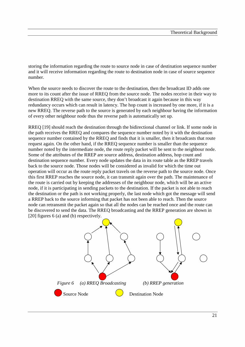
storing the information regarding the route to source node in case of destination sequence number and it will receive information regarding the route to destination node in case of source sequence number. When the source needs to discover the route to the destination, then the broadcast ID adds one more to its count after the issue of RREQ from the source node. The nodes receive in their way to destination RREQ with the same source, they don’t broadcast it again because in this way redundancy occurs which can result in latency. The hop count is increased by one more, if it is a new RREQ. The reverse path to the source is generated by each neighbour having the information of every other neighbour node thus the reverse path is automatically set up. RREQ [19] should reach the destination through the bidirectional channel or link. If some node in the path receives the RREQ and compares the sequence number noted by it with the destination sequence number contained by the RREQ and finds that it is smaller, then it broadcasts that route request again. On the other hand, if the RREQ sequence number is smaller than the sequence number noted by the intermediate node, the route reply packet will be sent to the neighbour node. Some of the attributes of the RREP are source address, destination address, hop count and destination sequence number. Every node updates the data in its route table as the RREP travels back to the source node. Those nodes will be considered as invalid for which the time out operation will occur as the route reply packet travels on the reverse path to the source node. Once this first RREP reaches the source node, it can transmit again over the path. The maintenance of the route is carried out by keeping the addresses of the neighbour node, which will be an active node, if it is participating in sending packets to the destination. If the packet is not able to reach the destination or the path is not working properly, the last node which got the message will send a RREP back to the source informing that packet has not been able to reach. Then the source node can retransmit the packet again so that all the nodes can be reached once and the route can be discovered to send the data. The RREQ broadcasting and the RREP generation are shown in [20] figures 6 (a) and (b) respectively.
Figure 6 (a) RREQ Broadcasting (b) RREP generation Source Node Destination Node
Theoretical Background
22
Three different kinds of modes of communication, provided by the ADOV (Ad hoc On Demand Distance Vector) are unicast, broadcast, and multicast. Unicast and multicast have been described in detail in [20] and describing how route discovery is done in these situations.
2.6.2 Cluster Tree Algorithm
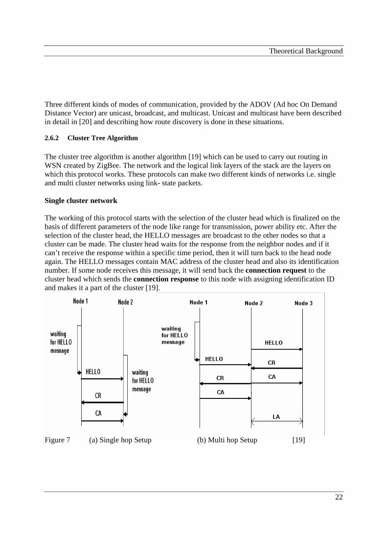
The cluster tree algorithm is another algorithm [19] which can be used to carry out routing in WSN created by ZigBee. The network and the logical link layers of the stack are the layers on which this protocol works. These protocols can make two different kinds of networks i.e. single and multi cluster networks using link- state packets. Single cluster network The working of this protocol starts with the selection of the cluster head which is finalized on the basis of different parameters of the node like range for transmission, power ability etc. After the selection of the cluster head, the HELLO messages are broadcast to the other nodes so that a cluster can be made. The cluster head waits for the response from the neighbor nodes and if it can’t receive the response within a specific time period, then it will turn back to the head node again. The HELLO messages contain MAC address of the cluster head and also its identification number. If some node receives this message, it will send back the connection request to the cluster head which sends the connection response to this node with assigning identification ID and makes it a part of the cluster [19].
Figure 7 (a) Single hop Setup (b) Multi hop Setup [19]

Theoretical Background
23
The figures 7 (a) and (b) are describing the scenario of cluster head selection [19] in cluster network with involvement of single hop and multi-hops respectively. CA is the abbreviation for Connection Acknowledgement and CR is for the Correction Request. The problem of the cluster head is that it will stop the HELLO message. There is a LINK STATE REPORT (LSR) that is sent to the cluster head from the node in case it is exchanging the HELLO messages with the node of some other cluster. The changes in the topology are also dependent on the LSR as it contains the list of a node neighbour. If some change in the network is required like more links from a node or some other kind of transition in the network which changes the whole topology, then the TOPOLOGY UPDATE message will be generated. Multi-cluster Network The working of the cluster tree algorithm in multi-cluster network can be summarized in the following points. [19]
• There is a device needed (which can be named as Designated Device or DD) to form a network. As multi-cluster involves more than one cluster, so this device (DD), which acts as a cluster head on joining the network, sends the HELLO messages to the cluster which is in the neighbour of first cluster for connection.
• If the second cluster accepts the message, it will send the request for connection to the
cluster head of the first cluster. The DD assigns a new cluster ID to the node acting as the cluster head of the second cluster. In this way the connection is established. Cluster ID and the node ID are very important to note as they form a kind of logical link for the routing of the packets.
• If the cluster head of the second cluster receives the message from the DD, then it will act
as a border for the parent cluster and the network connection request is generated. This makes the connection with the first cluster and connection response is also generated.
• The second cluster is assigned a new cluster ID from the parent cluster and it informs
about this to all the nodes belonging to this cluster. The border node forwards the packets coming from the one cluster network to the other cluster making the network.
• In case of multi-cluster, the NETWORK LINK STATE REPORT is maintained just like
LSR in case of single cluster, but the difference in this case is that instead of having the list of neighbour nodes, it is having the list of the neighbour clusters. This helps in making the changes in the topology of the network involving different clusters by issuing the topology update function.
• Figures and more detail regarding the multi-cluster network can be seen in [19].

Theoretical Background
24
2.6.3 Message routing
This is the basic type of algorithm used during the routing of messages in the wireless sensor networks. The node checks the address of the destination node in the table setup by the neighbour node. If the destination is found in the table of the neighbour node, then it responds to the first node by sending success message and set up a route for exchanging messages. Otherwise, in the similar way, the messages are sent to the other nodes in a flooding manner to find out the destination so that communication can be done. For instance when the nodes acting as the ZigBee End Devices (ZEDs) are in a sleep mode, then the ZigBee Routers (ZR) store the messages for them and transfer to them when they awake from the sleep mode to the active mode. It is the basic kind of algorithm used during the routing of data in the ZigBee sensor networks. [8]
2.6.4 Neighbour routing
This is also another basic type of algorithm used when routing is carried out by the network layer of the ZigBee stack. The node or device acting as a ZigBee Coordinator or ZigBee Router is responsible for maintaining the status of the nodes in their neighbour. This thing is done by the table where the ZC or ZR maintains for entering the data related the neighbour ZigBee devices. The destination device can receive the messages directly from the source device if it is the physical range of the sending device. The same procedure is followed by all the nodes along the route to destination to record the data of the neighbours in the table. In this way the possible routes to the destination are examined by recording the best route found in the routing tables maintained by all devices. [8]
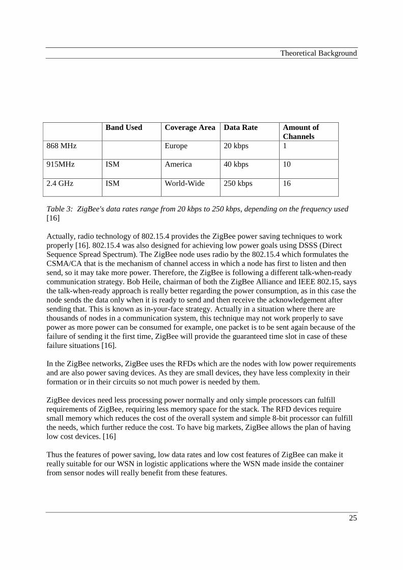
2.7 ZigBee: Low power, low cost, low data rate Technology One of the problems of the wireless sensors is that they require too much power to operate properly [16]. But ZigBee gives batteries a long life with which they can stay alive for months or even years. Also the ZigBee devices are much cheaper than other devices. The low data rate will play an important role in the success of ZigBee in future as the companies will focus on the lost cost and low data rate solutions for their problems rather than expensive ones. The data rates (shown in table 3) can be 20 kbps to 250 kbps depending upon the frequency used which is quite less compared to the ones supported by the Bluetooth (3 Mbps) and Wi-Fi's 802.11g technology (54 Mbps). Because ZigBee uses low rate, it will help to achieve the goals of Low power and low cost. These low rate requirements allow ZigBee node to sleep for some intervals to save power and energy and it wakes up again according to the need and then turns to the sleep mode again. Even in the sleeping mode, the ZigBee can change the state to active mode within 15 milliseconds which is not a big delay while changing the modes.
Theoretical Background
25
Band Used Coverage Area Data Rate Amount of
Channels 868 MHz Europe 20 kbps 1
915MHz ISM America 40 kbps 10
2.4 GHz ISM World-Wide 250 kbps 16
Table 3: ZigBee's data rates range from 20 kbps to 250 kbps, depending on the frequency used [16] Actually, radio technology of 802.15.4 provides the ZigBee power saving techniques to work properly [16]. 802.15.4 was also designed for achieving low power goals using DSSS (Direct Sequence Spread Spectrum). The ZigBee node uses radio by the 802.15.4 which formulates the CSMA/CA that is the mechanism of channel access in which a node has first to listen and then send, so it may take more power. Therefore, the ZigBee is following a different talk-when-ready communication strategy. Bob Heile, chairman of both the ZigBee Alliance and IEEE 802.15, says the talk-when-ready approach is really better regarding the power consumption, as in this case the node sends the data only when it is ready to send and then receive the acknowledgement after sending that. This is known as in-your-face strategy. Actually in a situation where there are thousands of nodes in a communication system, this technique may not work properly to save power as more power can be consumed for example, one packet is to be sent again because of the failure of sending it the first time, ZigBee will provide the guaranteed time slot in case of these failure situations [16]. In the ZigBee networks, ZigBee uses the RFDs which are the nodes with low power requirements and are also power saving devices. As they are small devices, they have less complexity in their formation or in their circuits so not much power is needed by them. ZigBee devices need less processing power normally and only simple processors can fulfill requirements of ZigBee, requiring less memory space for the stack. The RFD devices require small memory which reduces the cost of the overall system and simple 8-bit processor can fulfill the needs, which further reduce the cost. To have big markets, ZigBee allows the plan of having low cost devices. [16] Thus the features of power saving, low data rates and low cost features of ZigBee can make it really suitable for our WSN in logistic applications where the WSN made inside the container from sensor nodes will really benefit from these features.
Theoretical Background
26
2.8 Logistic telemetry applications In these applications, data from devices, that are monitoring goods, are transferred to centralized part of the system where this data (information about goods) will be analyzed. Tracking of goods is monitored closely and reports are continuously sent to the central storage. Nowadays, the importance of logistics is increasing and to have competitive advantage, companies use logistic approach. One of the most important logistic activities is transportation, so the companies have to develop a good logistic strategy plan. To achieve competitive advantage and to forge sustainable customer relations, companies have to take logistic support. Transportations usually contribute the largest share of the overall logistic costs. Transportation management is one area in logistics system management which is developing really fast. Logistics as an approach to manage the information flow plays an important role in satisfying the needs of the customers and their requirements. A lot of issues like energy conservation, availability and reliability in a secure way are important to be considered while designing these kinds of logistic applications [13]. As in logistic applications, the items are placed inside the pallets inside the container carried by truck, so there are different kinds of design requirements which are to be considered when we talk about the logistic telemetry applications. Some of these factors are [14]:
• Device Quantity It is important to determine the number of items that will be in one pallet in a container because the pallet space will be limited for a specific number of items so as the ISO container space. The power transmitted by the devices, which makes a kind of wireless sensor network, decides the number of the devices required to work fully inside a container and ensures that every device is addressed properly.
• Network topology The topology, which will be used to make the wireless sensor network, is also important because it is going to decide how the devices will communicate among each other. Topologies will be chosen among Mesh, Star or Cluster Tree topology according to the need of communication.
Theoretical Background
27
• Dynamicity There can be two different kinds of situations in which objects can be completely dynamic and static. Logistic telemetry applications are in a static state for most of the time during transferring but during the reloading situations, the state changes from static to dynamic. It is very important to assure the state of the items during the reloading state, as there is a big danger that any item can be damaged or misplaced.
Theoretical Background
28
2.9 System designs in logistic environments We shall first see the designs of logistic telemetry situations in ships, trucks and airplanes in which ZigBee can fit in.
2.9.1 Design of systems in ships
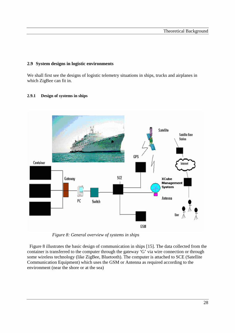
Figure 8: General overview of systems in ships
Figure 8 illustrates the basic design of communication in ships [15]. The data collected from the container is transferred to the computer through the gateway ‘G’ via wire connection or through some wireless technology (like ZigBee, Bluetooth). The computer is attached to SCE (Satellite Communication Equipment) which uses the GSM or Antenna as required according to the environment (near the shore or at the sea)

Theoretical Background
29
2.9.2 Design of systems in Airplanes
Figure 9: General overview of systems in airplanes [15]
The containers are placed actually in the deck of the airplane from where the gateway node collets the data and then sends it to the LAN (Local Area Network) [15]. Figure 9 shows that the gateway node can be connected to the LAN through some wireless system like the WLAN or the ZigBee. The data is transferred to the SCE and then to the satellites, where the data can be obtained by the end user at the satellite base stations through the internet using the XCube management system.
Theoretical Background
30
2.9.3 Design of systems in Trucks
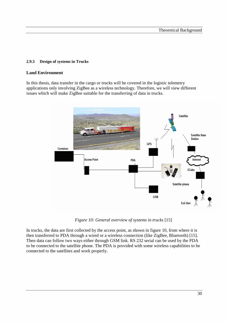
Land Environment In this thesis, data transfer in the cargo or trucks will be covered in the logistic telemetry applications only involving ZigBee as a wireless technology. Therefore, we will view different issues which will make ZigBee suitable for the transferring of data in trucks.
Figure 10: General overview of systems in trucks [15] In trucks, the data are first collected by the access point, as shown in figure 10, from where it is then transferred to PDA through a wired or a wireless connection (like ZigBee, Bluetooth) [15]. Then data can follow two ways either through GSM link. RS 232 serial can be used by the PDA to be connected to the satellite phone. The PDA is provided with some wireless capabilities to be connected to the satellites and work properly.
Theoretical Background
31
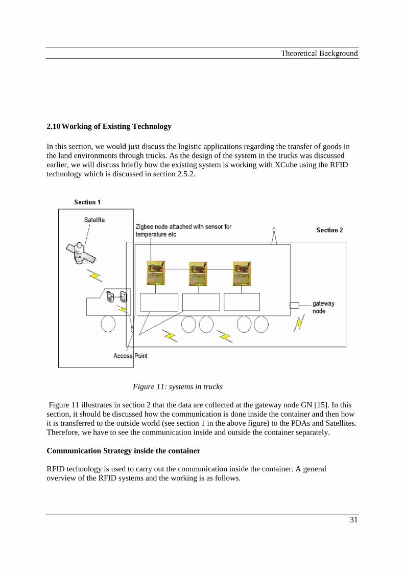
2.10 Working of Existing Technology In this section, we would just discuss the logistic applications regarding the transfer of goods in the land environments through trucks. As the design of the system in the trucks was discussed earlier, we will discuss briefly how the existing system is working with XCube using the RFID technology which is discussed in section 2.5.2.
Figure 11: systems in trucks
Figure 11 illustrates in section 2 that the data are collected at the gateway node GN [15]. In this section, it should be discussed how the communication is done inside the container and then how it is transferred to the outside world (see section 1 in the above figure) to the PDAs and Satellites. Therefore, we have to see the communication inside and outside the container separately. Communication Strategy inside the container RFID technology is used to carry out the communication inside the container. A general overview of the RFID systems and the working is as follows.

Theoretical Background
32
2.10.1 General overview of the RFID systems and the working inside container
RFID system is a combination of three things, namely antenna, interrogator and the tags. The interrogator, which works as a reader and writer, collets the data from the tags and passes to the outside environment through wire or wireless connection and can also write to the tags. The communication with RFID is performed by the antenna which emits the RF signals to handle the read or write operation for the tag. RFID tags are of two types: Active Tags and Passive tags [15]. Active tags
• They are provided with their own source of power. • Readers can access these tags from far distances as they transmit a very strong signal to
long distances. • They operate on quite high frequencies like 455 MHz, 2.45 GHz, or 5.8 GHz. • Because of the power source available internally, they are more expensive.
Passive tags
• They are inexpensive with about 2 Kbits of memory and not provided with battery. • They are smaller in size as compared to the active tags and just cover short ranges. • They are just for the read only applications.
The antenna of the tag should be designed with the aim of increasing power of the tag [15]. The antenna should be omni directional, robust and cheap. The impedance, antenna type, radiation pattern and multipath effects are some points to be considered when choosing an antenna. Here we have to propose a local interrogator for a passive RFID tag. The passive tags on the items have the data which are obtained by this interrogator. In one case, in the container, reader generates the polls or signals at some specific intervals of time. For these polls, low power signals are used which then wake up the tags from the sleeping mode. In the active mode, the tags use some pseudo-random protocol, which is a special protocol to communicate with the interrogator of the RFID. There are two modes used by tag, the sleep and active modes. Tag goes to the sleep mode when it does not receive any radio signal. Time Division Multiple Access (TDMA) is used to carry out the link between reader and tag in the cellular systems. In another scenario, the active tags use the data stored in them to beacon it and send a kind of small message to the reader who gives acknowledgement to the messages at regular intervals. A lot of tags may try to communicate with the reader simultaneously which can create a kind of collision, To deal with this problem, anti-collision mechanisms like Binary Tree Scheme, Query-
Theoretical Background
33
Tree Scheme, Asynchronous methods and Simultaneous Identification (SID) Mechanism are used. The signal inside the container experiences multipath propagation effects and attenuation. Different data encoding and data modulation techniques are also used for the propagation of the signal.
2.10.2 Communication to outside the container
The interrogator receives all the data from the items and allows the retrieval when ever it is demanded [15]. The interrogator is also provided with an 802.11b WLAN PC-Card (link between interrogator and WLAN transceiver) which transfers the data to the WLAN transceiver situated outside the container. Another way to carry out the communication between the transceiver and the interrogator is to have a wired connection between them which can be much more reliable. The access point placed on the truck receives data from the WLAN transceiver and then sends them further by using other communication means.
ZigBee suitability in WSN in Logistic Telemetry Applications
34
3 ZigBee suitability in WSN in Logistic Telemetry Applications
(METHODOLOGY AND ANALYSIS) As we have discussed so far the ZigBee technology in detail, so now we see its suitability in wireless sensor networks in logistic telemetry situations. In this section, we have to analyze which features of ZigBee technology will make it suitable for the WSN in logistic situations.
3.1 Possible suitable ZigBee Network Design
ZigBee modules (working fully functional) are designed, implemented and then tested. There are two different kinds of modules; one is with both networking and PHY/MAC stack layers while the other just consists of the PHY/MAC stack layer. These ZigBee modules can be used to test any attribute related sensor networking like test temperature sensor networking or other attributes that can also be evaluated. One ZigBee module is called ‘RF + MCU‘ module, as it has both the RF and MCU part and the other module only has RF part so that is why it is known as RF module. In RF + MCU module, CC2420 chip manufactured by the Chipcon is used by the RF part while microcontroller part uses the ATmega128L chip provided by the Atmel technology [17]. We can build ZigBee applications as there are both microcontroller and connector in the RF + MCU module. (see [17] for details of ZigBee ready modules)Through the connector, we can connect a sensor to the RF + MCU module, for example, if the sensor relating temperature is attached to the module, it will transfer data through the coordinator which displays them on the LCD display. Similar to our telemetry applications, different kinds of sensor for temperature, humidity, acceleration etc can be attached to the module to obtain the value of that attribute. The two modules have a PCB which uses a 4 layer FR-4 board. [17] There are two internal layers that are used for power and ground purposes while routing is done by the top and bottom layers. Microcontroller chips, antenna, RF and connector are aggregated on the board. ZigBee modules, which can be combined to a make large sensor network can be programmed to three different kinds of devices; Network Coordinator, Full Function device and Reduced Function Device. These devices can be combined to make three different kinds of topologies like star, cluster tree and mesh topology as discussed in section 2.3.3.
(METHODOLOGY AND ANALYSIS)
35
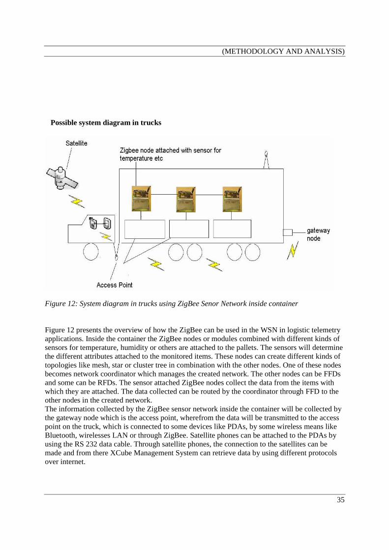
Possible system diagram in trucks
Figure 12: System diagram in trucks using ZigBee Senor Network inside container Figure 12 presents the overview of how the ZigBee can be used in the WSN in logistic telemetry applications. Inside the container the ZigBee nodes or modules combined with different kinds of sensors for temperature, humidity or others are attached to the pallets. The sensors will determine the different attributes attached to the monitored items. These nodes can create different kinds of topologies like mesh, star or cluster tree in combination with the other nodes. One of these nodes becomes network coordinator which manages the created network. The other nodes can be FFDs and some can be RFDs. The sensor attached ZigBee nodes collect the data from the items with which they are attached. The data collected can be routed by the coordinator through FFD to the other nodes in the created network. The information collected by the ZigBee sensor network inside the container will be collected by the gateway node which is the access point, wherefrom the data will be transmitted to the access point on the truck, which is connected to some devices like PDAs, by some wireless means like Bluetooth, wirelesses LAN or through ZigBee. Satellite phones can be attached to the PDAs by using the RS 232 data cable. Through satellite phones, the connection to the satellites can be made and from there XCube Management System can retrieve data by using different protocols over internet.
(METHODOLOGY AND ANALYSIS)
36
For designing the network for the WSN in logistic applications, it is important to examine the topology used for making the network and the routing algorithm used. There can be two kinds of scenarios in a ZigBee network, which can be either a single hop or a multi-hop communication. It is important to study the scheme, which will best suit accordingly in given WSN to conserve energy that is a main factor to see while carrying out communication.
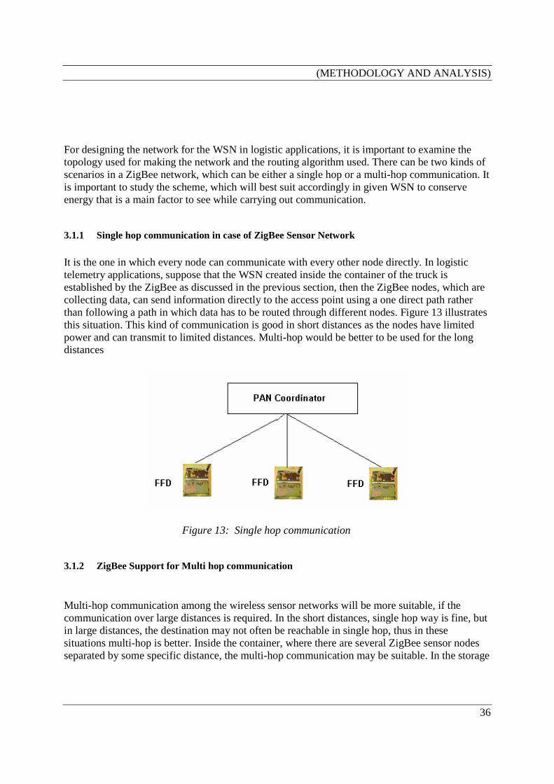
3.1.1 Single hop communication in case of ZigBee Sensor Network
It is the one in which every node can communicate with every other node directly. In logistic telemetry applications, suppose that the WSN created inside the container of the truck is established by the ZigBee as discussed in the previous section, then the ZigBee nodes, which are collecting data, can send information directly to the access point using a one direct path rather than following a path in which data has to be routed through different nodes. Figure 13 illustrates this situation. This kind of communication is good in short distances as the nodes have limited power and can transmit to limited distances. Multi-hop would be better to be used for the long distances
Figure 13: Single hop communication
3.1.2 ZigBee Support for Multi hop communication
Multi-hop communication among the wireless sensor networks will be more suitable, if the communication over large distances is required. In the short distances, single hop way is fine, but in large distances, the destination may not often be reachable in single hop, thus in these situations multi-hop is better. Inside the container, where there are several ZigBee sensor nodes separated by some specific distance, the multi-hop communication may be suitable. In the storage
(METHODOLOGY AND ANALYSIS)
37
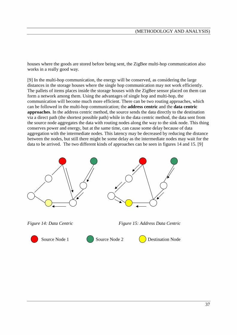
houses where the goods are stored before being sent, the ZigBee multi-hop communication also works in a really good way. [9] In the multi-hop communication, the energy will be conserved, as considering the large distances in the storage houses where the single hop communication may not work efficiently. The pallets of items places inside the storage houses with the ZigBee sensor placed on them can form a network among them. Using the advantages of single hop and multi-hop, the communication will become much more efficient. There can be two routing approaches, which can be followed in the multi-hop communication; the address centric and the data centric approaches. In the address centric method, the source sends the data directly to the destination via a direct path (the shortest possible path) while in the data centric method, the data sent from the source node aggregates the data with routing nodes along the way to the sink node. This thing conserves power and energy, but at the same time, can cause some delay because of data aggregation with the intermediate nodes. This latency may be decreased by reducing the distance between the nodes, but still there might be some delay as the intermediate nodes may wait for the data to be arrived. The two different kinds of approaches can be seen in figures 14 and 15. [9]
Figure 14: Data Centric Figure 15: Address Data Centric Source Node 1 Source Node 2 Destination Node
(METHODOLOGY AND ANALYSIS)
38
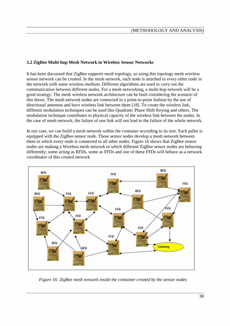
3.2 ZigBee Multi-hop Mesh Network in Wireless Sensor Networks It has been discussed that ZigBee supports mesh topology, so using this topology mesh wireless sensor network can be created. In the mesh network, each node is attached to every other node in the network with some wireless medium. Different algorithms are used to carry out the communication between different nodes. For a mesh networking, a multi-hop network will be a good strategy. The mesh wireless network architecture can be built considering the scenario of this thesis. The mesh network nodes are connected in a point-to-point fashion by the use of directional antennas and have wireless link between them [18]. To create the wireless link, different modulation techniques can be used like Quadratic Phase Shift Keying and others. The modulation technique contributes to physical capacity of the wireless link between the nodes. In the case of mesh network, the failure of one link will not lead to the failure of the whole network. In our case, we can build a mesh network within the container according to its size. Each pallet is equipped with the ZigBee sensor node. These sensor nodes develop a mesh network between them in which every node is connected to all other nodes. Figure 16 shows that ZigBee sensor nodes are making a Wireless mesh network in which different ZigBee sensor nodes are behaving differently; some acting as RFDs, some as FFDs and one of these FFDs will behave as a network coordinator of this created network
Figure 16: ZigBee mesh network inside the container created by the sensor nodes
(METHODOLOGY AND ANALYSIS)
39
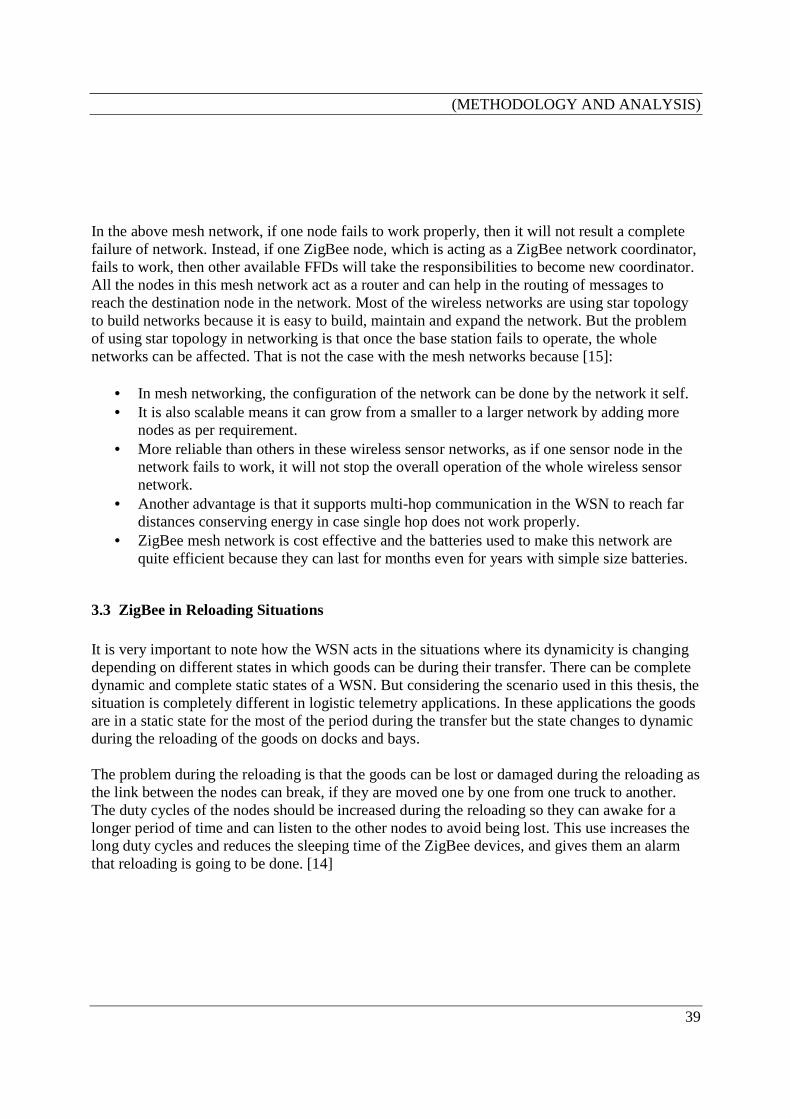
In the above mesh network, if one node fails to work properly, then it will not result a complete failure of network. Instead, if one ZigBee node, which is acting as a ZigBee network coordinator, fails to work, then other available FFDs will take the responsibilities to become new coordinator. All the nodes in this mesh network act as a router and can help in the routing of messages to reach the destination node in the network. Most of the wireless networks are using star topology to build networks because it is easy to build, maintain and expand the network. But the problem of using star topology in networking is that once the base station fails to operate, the whole networks can be affected. That is not the case with the mesh networks because [15]:
• In mesh networking, the configuration of the network can be done by the network it self. • It is also scalable means it can grow from a smaller to a larger network by adding more
nodes as per requirement. • More reliable than others in these wireless sensor networks, as if one sensor node in the
network fails to work, it will not stop the overall operation of the whole wireless sensor network.
• Another advantage is that it supports multi-hop communication in the WSN to reach far distances conserving energy in case single hop does not work properly.
• ZigBee mesh network is cost effective and the batteries used to make this network are quite efficient because they can last for months even for years with simple size batteries.
3.3 ZigBee in Reloading Situations It is very important to note how the WSN acts in the situations where its dynamicity is changing depending on different states in which goods can be during their transfer. There can be complete dynamic and complete static states of a WSN. But considering the scenario used in this thesis, the situation is completely different in logistic telemetry applications. In these applications the goods are in a static state for the most of the period during the transfer but the state changes to dynamic during the reloading of the goods on docks and bays. The problem during the reloading is that the goods can be lost or damaged during the reloading as the link between the nodes can break, if they are moved one by one from one truck to another. The duty cycles of the nodes should be increased during the reloading so they can awake for a longer period of time and can listen to the other nodes to avoid being lost. This use increases the long duty cycles and reduces the sleeping time of the ZigBee devices, and gives them an alarm that reloading is going to be done. [14]

(METHODOLOGY AND ANALYSIS)
40
How ZigBee can be a motivating factor Following are some important factors provided by the ZigBee which can play an important role in the reloading conditions.
• ZigBee supports the use of multi-hop routing within the WSN created by the ZigBee sensor nodes, so it can be a suitable option during reloading. If the multi-hop communication is carried out, then the nodes can be very near to each other during the reloading and can record the data associated with the neighbour node. There can be different multi hop routing algorithms discussed above in section 2.6 which can be used in these conditions.
• Especially in these kinds of situations, Cluster Tree Protocols can be motivated to use, as
the cluster of the WSN created inside one truck can develop a route to the other cluster in another truck. The Designation Device of the first cluster can assign the second cluster ID after the connection request from the second cluster. The connection between these two clusters can be made. The single and multiple cluster tree networks can be used to develop the connection between different nodes.
• As in the ZigBee sensor network, the devices can send data over long distances so during
the reloading, the devices can maintain connection between them thorough multi-hop routing.
• The duty cycles of the ZigBee devices can be made longer, so that the devices can wake
up or remain active for a longer time reducing the sleep time during the reloading. Requires a complex approach for designing system for reloading To carry out the reloading, high level wireless senor network is required which can be implemented by taking care of all the features including which multi-hop routing strategies to be used, duty cycle requirements and the successful communication among the WSN. Practical implementation will suggest the routing technique which will be best suitable in reloading of goods in the telemetry application involving ZigBee. Implementation of some multi-hop routing algorithm for the reloading will ease or solve the problems; the goods are facing during this stage. The design of the different ZigBee protocols and the system structure during the reloading stage need more research in this field which is placed in the future work section 5.

(METHODOLOGY AND ANALYSIS)
41
3.4 Analysis
3.4.1 Low power, low cost and low data rate It can be said that low power, low cost and low data rates are the points which really make ZigBee suitable for the target applications in this thesis. The following points in the table 4 best describe how these features are really important. Need Low Power
The wireless sensors make the WSN need considerable power to operate but looking at the ZigBee sensors they require only small amount of power to carry out operations. This low power feature works properly by using the radio technology provided by the 802.15.4 (uses the DSSS modulation technique to achieve low power).
Long life Batteries
The batteries required for providing power or energy are normal size batteries which can stay alive for longer period of times. These batteries can work properly for months and years without the need to be replaced or recharged while the other wireless technologies like Bluetooth require batteries to be recharged at regular intervals of time. So in case of WSN created inside the container by ZigBee sensor nodes, one does not need to replace the batteries used for the sensors.
Low Cost
Low cost feature of ZigBee makes it suitable to be used in WSNs just like in logistic telemetry applications, rather than using other expensive wireless technologies. When we will be using these low cost sensor nodes, the cost for building the WSN inside the container will also be small.
Low data rates
ZigBee is providing the low data rates at different frequency bands making in available to work in different parts of the world. The low bandwidths used for the ZigBee allow the sensor nodes making the WSN inside the container carried by the truck to sleep for some time saving the power. When the sensor node will be in the sleeping mode, it will save power and cost respectively. The cost will be small as the same batteries will be used for more times without being recharged.
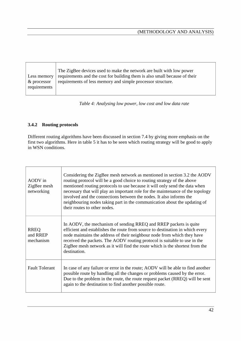
(METHODOLOGY AND ANALYSIS)
42
Less memory & processor requirements
The ZigBee devices used to make the network are built with low power requirements and the cost for building them is also small because of their requirements of less memory and simple processor structure.
Table 4: Analysing low power, low cost and low data rate
3.4.2 Routing protocols Different routing algorithms have been discussed in section 7.4 by giving more emphasis on the first two algorithms. Here in table 5 it has to be seen which routing strategy will be good to apply in WSN conditions. AODV in ZigBee mesh networking
Considering the ZigBee mesh network as mentioned in section 3.2 the AODV routing protocol will be a good choice to routing strategy of the above mentioned routing protocols to use because it will only send the data when necessary that will play an important role for the maintenance of the topology involved and the connections between the nodes. It also informs the neighbouring nodes taking part in the communication about the updating of their routes to other nodes.
RREQ and RREP mechanism
In AODV, the mechanism of sending RREQ and RREP packets is quite efficient and establishes the route from source to destination in which every node maintains the address of their neighbour node from which they have received the packets. The AODV routing protocol is suitable to use in the ZigBee mesh network as it will find the route which is the shortest from the destination.
Fault Tolerant
In case of any failure or error in the route; AODV will be able to find another possible route by handling all the changes or problems caused by the error. Due to the problem in the route, the route request packet (RREQ) will be sent again to the destination to find another possible route.
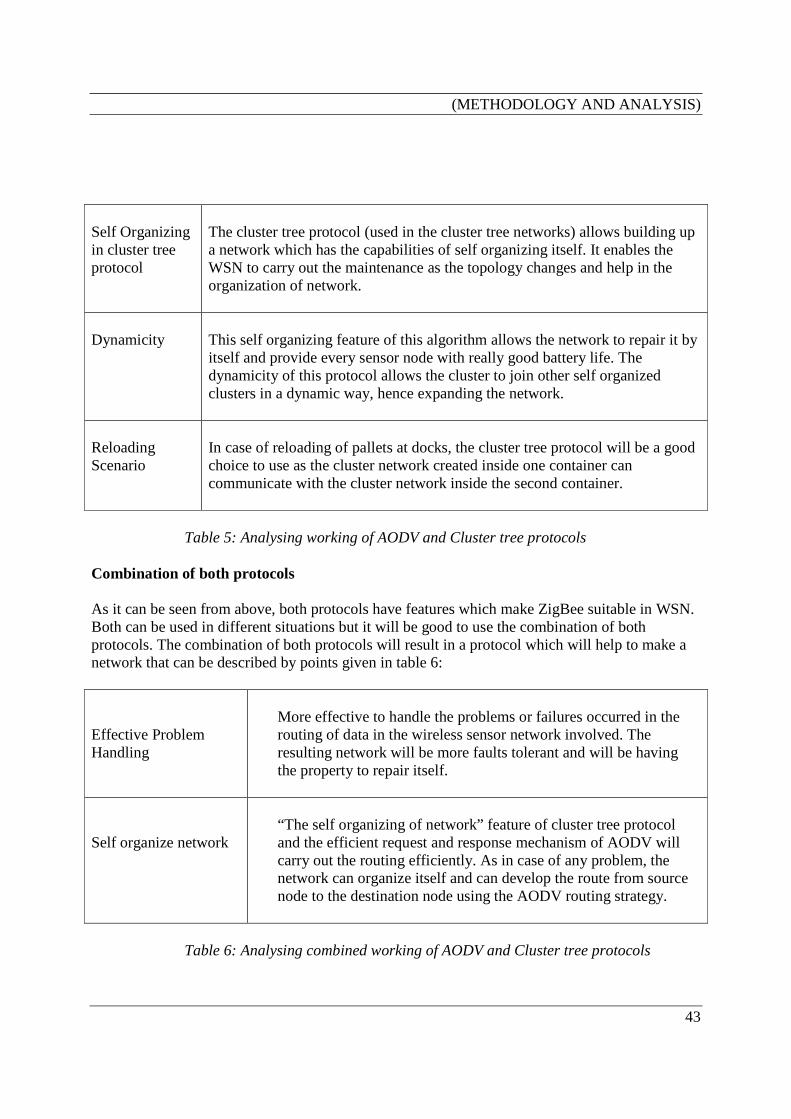
(METHODOLOGY AND ANALYSIS)
43
Self Organizing in cluster tree protocol
The cluster tree protocol (used in the cluster tree networks) allows building up a network which has the capabilities of self organizing itself. It enables the WSN to carry out the maintenance as the topology changes and help in the organization of network.
Dynamicity
This self organizing feature of this algorithm allows the network to repair it by itself and provide every sensor node with really good battery life. The dynamicity of this protocol allows the cluster to join other self organized clusters in a dynamic way, hence expanding the network.
Reloading Scenario
In case of reloading of pallets at docks, the cluster tree protocol will be a good choice to use as the cluster network created inside one container can communicate with the cluster network inside the second container.
Table 5: Analysing working of AODV and Cluster tree protocols Combination of both protocols As it can be seen from above, both protocols have features which make ZigBee suitable in WSN. Both can be used in different situations but it will be good to use the combination of both protocols. The combination of both protocols will result in a protocol which will help to make a network that can be described by points given in table 6: Effective Problem Handling
More effective to handle the problems or failures occurred in the routing of data in the wireless sensor network involved. The resulting network will be more faults tolerant and will be having the property to repair itself.
Self organize network
“The self organizing of network” feature of cluster tree protocol and the efficient request and response mechanism of AODV will carry out the routing efficiently. As in case of any problem, the network can organize itself and can develop the route from source node to the destination node using the AODV routing strategy.
Table 6: Analysing combined working of AODV and Cluster tree protocols

(METHODOLOGY AND ANALYSIS)
44
3.4.3 Synchronization Table 7 gives important analyses of different synchronizing factors. CSMA-CA
The use of the CSMA-CA in the ZigBee network, which uses back off algorithms strategy, gives the devices a way to access channels. In this method, the different slots of the super frame are allocated for different devices, so they are guaranteed to receive these slots to perform the operation, which makes ZigBee a suitable technology; then there will be less number of collisions, as the devices will have the guaranteed slots assigned to them.
Energy conservation
ZigBee network can achieve the energy conservation factor as the devices control the transfer of the data on the PAN.
Synchronizing
The devices can be synchronized according to the clock time of personal area network coordinator depending on the network which can be beacon enabled or not.
Guaranteed Time Slots
As the super frame is divided into 16 slots, it is divided into contention access and contention free periods. These slots are GTS, so the devices associated with them will have their guaranteed slot and will be synchronized with time given for the slot; thus no wastage of energy will occur. The devices can go to the sleep mode, if the network is beacon enabled and wake up again when the beacon arrives. This process will save energy in the involved ZigBee network.
Table 7: Synchronization Factor
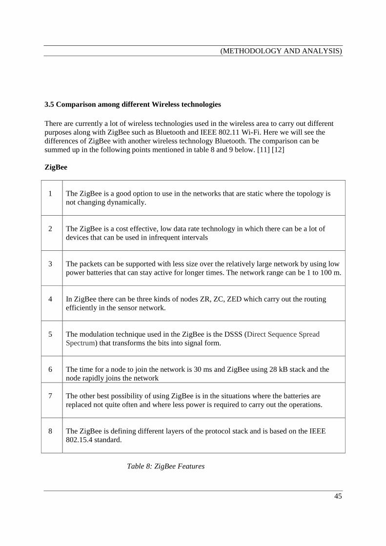
(METHODOLOGY AND ANALYSIS)
45
3.5 Comparison among different Wireless technologies There are currently a lot of wireless technologies used in the wireless area to carry out different purposes along with ZigBee such as Bluetooth and IEEE 802.11 Wi-Fi. Here we will see the differences of ZigBee with another wireless technology Bluetooth. The comparison can be summed up in the following points mentioned in table 8 and 9 below. [11] [12] ZigBee 1
The ZigBee is a good option to use in the networks that are static where the topology is not changing dynamically.
2
The ZigBee is a cost effective, low data rate technology in which there can be a lot of devices that can be used in infrequent intervals
3
The packets can be supported with less size over the relatively large network by using low power batteries that can stay active for longer times. The network range can be 1 to 100 m.
4
In ZigBee there can be three kinds of nodes ZR, ZC, ZED which carry out the routing efficiently in the sensor network.
5
The modulation technique used in the ZigBee is the DSSS (Direct Sequence Spread Spectrum) that transforms the bits into signal form.
6
The time for a node to join the network is 30 ms and ZigBee using 28 kB stack and the node rapidly joins the network
7
The other best possibility of using ZigBee is in the situations where the batteries are replaced not quite often and where less power is required to carry out the operations.
8
The ZigBee is defining different layers of the protocol stack and is based on the IEEE 802.15.4 standard.
Table 8: ZigBee Features
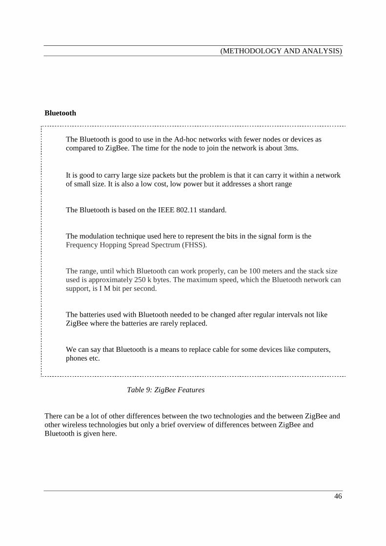
(METHODOLOGY AND ANALYSIS)
46
Bluetooth
The Bluetooth is good to use in the Ad-hoc networks with fewer nodes or devices as compared to ZigBee. The time for the node to join the network is about 3ms.
It is good to carry large size packets but the problem is that it can carry it within a network of small size. It is also a low cost, low power but it addresses a short range
The Bluetooth is based on the IEEE 802.11 standard.
The modulation technique used here to represent the bits in the signal form is the Frequency Hopping Spread Spectrum (FHSS).
The range, until which Bluetooth can work properly, can be 100 meters and the stack size used is approximately 250 k bytes. The maximum speed, which the Bluetooth network can support, is I M bit per second.
The batteries used with Bluetooth needed to be changed after regular intervals not like ZigBee where the batteries are rarely replaced.
We can say that Bluetooth is a means to replace cable for some devices like computers, phones etc.
Table 9: ZigBee Features
There can be a lot of other differences between the two technologies and the between ZigBee and other wireless technologies but only a brief overview of differences between ZigBee and Bluetooth is given here.
Discussion
47
4 Discussion This part discusses the factors which play an important role in selecting ZigBee, as a wireless technology for different solutions like WSN in logistic telemetry applications.
• First of all, unlike other wireless technology of its own kind, ZigBee is more cost effective, covers more range by using the batteries which last for months to years.
• The coverage area is very important to note here, that it provides different frequency
bands to different areas making it very suitable to be accepted as a global standard.
• Support for Mesh networking is another important and promising feature provided by the ZigBee to use in the logistic telemetry applications rather than using the other technologies of its own kind.
• There are also some appropriate algorithms which can be used in the multi-hop
communication to carry out the ZigBee routing.
• Different kinds of topologies (like star, mesh, cluster tree) can be used here which define different kinds of networks. So any topology can be chosen depending upon the design required for the network.
• It is very important to observe the updataions in different areas regarding ZigBee by
ZigBee Alliance that is defining this standard and its different features like ZigBee stack based on the IEEE 802.15.4 standard.
So, the above mentioned points are very important in discussing the ZigBee for the WSN in any application like logistic telemetry application.
Future work
48
5 Future work This section describes the different factors which are not covered by this thesis, and will be covered in future. They can be summarized in the following points:
• The Implementation of different kinds of multi-hop routing protocols supported by the ZigBee and to see their real working under the given standard conditions. This will lead to judge the suitability of ZigBee in the WSN in the logistic telemetry applications.
• Carry out more research on the design of the system for the reloading situations and to see
in detail the multi-hop routing strategies. This will help to find out different solutions and answers to a lot of issues involved in the reloading of goods.
• Developing some procedures or protocols which will carry out the communication from
inside the container to the outside involving the ZigBee devices creating a wireless sensor network inside the container.
Conclusion
49
6 Conclusion It can be concluded that ZigBee has a lot of features which make it suitable for the wireless sensor networks in different situations like logistic telemetry situations. It is a low cost, low power and low data rate wireless standard. Its support for multi-hop communication and mesh networking adds to its suitability for the WSNs. It supports different kinds of routing protocols which carry out routing in the wireless sensor networks. But it is still a very new technology to rely on and use in these kinds of tracking situations. As it is in the early stages of its development, so a great deal of work relating ZigBee is still have to be done. Thus, it is a growing technology and has all the features to become a globally accepted standard for logistic telemetry applications and many other applications.

References
50
7 References [1] Nikolaou, N.; Vaxevanakis, K.; Maniatis, S.; Venieris, I.; Zervos, N.; “Wireless technologies convergence: results and experience”; Wireless Communications and Networking Conference, 2000. WCNC. 2000 IEEE Volume 2, 23-28 Sept. 2000 Page(s):566 - 571 vol.2 [2] Johan Lönn, Jonas Olsson, ”ZigBee for wireless networking” Master Thesis, Department of Science and Technology Linköping University Norrköping, Sweden. March 15, 2005. [3] XCube Communications website, <http://www.x3-c.com>, Retrieval August 2005 [4] William C. Craig, Zigbee: "Wireless Control That Simply Works" , White paper, ZigBee Alliance < www.zigbee.org >, Retrieval September 2005 [5] ZigBee Alliance website, September 2002, “ZigBee Overview” Retrieval May 20, 2005. (http://www.zigbee.org/en/resources/zigbeeoverview4.pdf) [6] Home Toys Website, <www.hometoys.com>, Retrieval September 2005. (http://hometoys.com/htinews/oct03/articles/kinney/zigbee.htm) [7] “Part 15.4: Wireless Medium Access Control (MAC) and Physical Layer (PHY) Specifications for Low-Rate Wireless Personal Area Networks (LR-WPANs)”, Published by The Institute of Electrical and Electronics Engineers, Inc. 3 Park Avenue, New York, NY 10016-5997, USA. Print: SH95127, 1 October 2003. [8] ZigBee Alliance website, “Network Layer Technical Overview” Retrieval Date September, 2005. (http://www.zigbee.org/en/documents/zigbee-network-layer-technical-overview.pdf) [9] Rikard Andersson, Martin Sandberg, L´aszl´o Urszuly, “Open Secure Office Project Wireless Sensor Network”; Technical Report, IDE0502, January 2005 Master’s Thesis in Computer Systems Engineering and Electrical Engineering School of Information Science, Computer and Electrical Engineering Halmstad University, Sweden [10] Akyildiz, I.F.; Weilian Su; Sankarasubramaniam, Y.; Cayirci, E.; “A survey on sensor networks”
References
51
Communications Magazine, IEEE Volume 40, Issue 8, Aug. 2002 Page(s):102 - 114 [11] ZigBee Alliance website, “Emerging Standards: Where do ZigBee/UWB fit” Retrieval Date October, 2005. (http://www.zigbee.org/en/resources/documents/wicon_zigbee_standards_presentation.pdf) [12] Network World Website, <www.networkworld.com>, Retrieval October 2005. (http://www.networkworld.com/newsletters/wireless/2005/0228wireless1.html) [13] Korpela, J.; Tuominen, M.; “An analytic approach to the analysis and selection of transport services” Engineering Management Conference, 1994. 'Management in Transition: Engineering a Changing World', Proceedings of the 1994 IEEE International 17-19 Oct. 1994 Page(s):300 – 314 [14] Markus Adolfsson (http://www2.hh.se/staff/maad/ ), “A Survey on Designing Wireless Sensor Networks for Logistic Telemetry Applications”, School of Information Science, Computer and Electrical Engineering Halmstad University, Sweden [15] Debashish Ganguly, Venkata Phani Sankar.S, “Global Communication in Difficult Environments for Logistics Tracking and Monitoring Systems”; Technical report, IDE0507, January 2005 Master’s Thesis in Electrical Engineering School of Information Science, Computer and Electrical Engineering Halmstad University, Sweden [16] Techonline Website, < www.techonline.com >, Retrieval November 2005. (http://www.techonline.com/community/tech_topic/36561) [17] Johan Lönn, Jonas Olsson, Shaofang Gong, “ZigBee-ready modules for sensor networking”, Research paper written on the basis of master thesis described in [2] Department of Science and Technology Linköping University SE-60174 Norrköping, Sweden
References
52
[18] Kitahara, T.; Kishi, Y.; Imagawa, Y.; Tabata, K.; Nomoto, S.; Idoue, A.; “An adaptive load balancing in multi-hop mesh networks for broadband fixed wireless access systems”, Radio and Wireless Conference, 2004 IEEE 19-22 Sept. 2004 Page(s):463 – 466 [19] “ZigBee/IEEE 802.15.4 Summary” University of California Berkeley, ELECTRICAL ENGINEERING AND COMPUTER SCIENCES (http://www.eecs.berkeley.edu/~csinem/academic/publications/zigbee.pdf) [20] Royer, E.M.; Perkins, C.E.; “An implementation study of the AODV routing protocol” Wireless Communications and Networking Conference, 2000. WCNC. 2000 IEEE Volume 3, 23-28 Sept. 2000 Page(s):1003 - 1008 vol.3
[21] Smith, J.O.; Kamangar, F.A.; Ravi, N.; Cowin, G.; Shah, K.U.; “Anticipating the future of telematics” Networking, Sensing and Control, 2004 IEEE International Conference on Volume 2, 2004 Page(s):1276 - 1283 Vol.2


![AT08550: ZigBee Attribute Reporting · ZigBee Attribute Reporting [APPLICATION NOTE] Atmel-42334A-ZigBee-Attribute-Reporting -ApplicationNote_012015 3 1 Overview The ZigBee Specification](https://img.pdfslide.net/doc/110x75/5f43d267b58b3c15740a0db6/at08550-zigbee-attribute-reporting-zigbee-attribute-reporting-application-note.jpg)
![ZigBee Stack Profile: Platform restrictions for compliant ...read.pudn.com/.../3...ZigBee-Feature-Set-Profile.pdf · 11 [R2] ZigBee 04140r05, ZigBee Protocol Stack Settable Values](https://img.pdfslide.net/doc/110x75/5f183a7d6417c0751a61665e/zigbee-stack-profile-platform-restrictions-for-compliant-readpudncom3zigbee-feature-set-.jpg)