Embed Size (px)
Citation preview
ES-F-LF876V
MasterSeries® LF876VDouble Check Detector Backflow Prevention Assemblies (Type II)Size: 21⁄2" - 10"
LEAD FREE*
Job Name ––––––––––––––––––––––––––––––––––––––––––– Contractor ––––––––––––––––––––––––––––––––––––––––––––
Job Location ––––––––––––––––––––––––––––––––––––––––– Approval –––––––––––––––––––––––––––––––––––––––––––––
Engineer ––––––––––––––––––––––––––––––––––––––––––––– Contractor’s P.O. No. –––––––––––––––––––––––––––––––––––
Approval ––––––––––––––––––––––––––––––––––––––––––––– Representative ––––––––––––––––––––––––––––––––––––––––
FEBCO product specifications in U.S. customary units and metric are approximate and are provided for reference only. For precise measurements, please contact FEBCO Technical Service. FEBCO reserves the right to change or modify product design, construction, specifications, or materials with-out prior notice and without incurring any obligation to make such changes and modifications on FEBCO products previously or subsequently sold.
The FEBCO MasterSeries LF876V Double Check Detector Assembly is specifically designed to protect against possible backpressure and backsiphonage conditions for non-health hazard (i.e., pollutant) application in accordance with Local Governing Water Utility Code.
This Backflow Assembly is primarily used on potable drinking water systems and fire sprinkler systems, where Local Governing Code mandates protection from non-potable quality water being pumped or siphoned back into the potable water system.
FeaturesMain Valve:
• Inline Serviceable Assembly
• Horizontal “N-Pattern” Installations
• Vertical-Up “Z-Pattern” Installations
• No Special Tools Required for Servicing
• Captured Modular Spring Assembly
• Reversible & Replaceable Discs
• Field Replaceable Seats
• Ductile Iron Valve Body Design
• Stainless Steel Check Components
• Winterization feature with disc retainers and valve body drain ports
• Clapper Check Assembly
• Commonality between 1st & 2nd Check Components
• Captured O-ring Design
Auxiliary Bypass:
• Compact Bypass Design; Remains within Main Valve Assembly Profile
• Inline Serviceable 3⁄4" Backflow Assembly
• No Special Tools Required for Servicing
• Field Replaceable Seats & Discs
• Detect Potential Underground Water Leaks
• Detect Unauthorized Water Usage
SpecificationsThe FEBCO MasterSeries LF876V Double Check Detector Valve Assembly shall be installed on the potable water supply and at each point of cross-connection to protect against possible backpressure and backsiphonage conditions for non-health hazard (i.e., pollutant) applications. The assembly shall consist of a main line valve body composed of two (2) independently acting approved clapper style check modules with replaceable seats and disc rubbers. Servicing of both check modules does not require any special tools and are accessed through independent top entry covers. This assembly shall be fitted with approved UL/FM inlet/outlet resilient seated shutoff valves and contain four (4) properly located resilient seated test cocks as specified by AWWA Standard C510. The auxiliary bypass line contains a 5⁄8"x3⁄4" Water Meter that complies with ANSI/AWWA Standard C700 coupled with an approved check assembly. The bypass line is designed to detect leaks or unauthorized water usage of the water system while protecting against possible backpressure and backsiphonage conditions for non-health hazard (i.e., pollutant) application. The assembly shall be approved for horizontal and/or vertical-up installations while meeting the requirements of AWWA Standard C510 flow and pressure loss performance parameters.
Model LF876V Double Check Detector Assembly
*The wetted surface of this product contacted by consumable water contains less than 0.25% of lead by weight.
NOTICEInquire with governing authorities for local installation requirements
NOTICEThe information contained herein is not intended to replace the full product installation and safety information available or the experience of a trained product installer. You are required to thoroughly read all installation instructions and product safety information before beginning the installation of this product.
Options - SuffixOSY: UL/FM Approved OS&Y Gate Valves [ANSI/AWWA
C515 Compliant]
CFM: Totalizing Cubic feet/min 5⁄8"x 3⁄4" Water Meter [ANSI/AWWA C700 Compliant]
GPM: Totalizing Gallons/min 5⁄8"x 3⁄4" Water Meter [ANSI/AWWA C700 Compliant]
LG: Less Shutoff valves; This is NOT an APPROVED ASSEMBLY
Example Ordering Description:
4" LF876V-OSY-GPM - Valve Assembly fitted with OS&Y Shutoff Valves & Gallons per Minute Water Meter
4" LF876V-OSY-CFM - Valve Assembly fitted with OS&Y Shutoff Valves & Cubic Feet per Minute Water Meter
Available Components
Wye Strainer: FDA Approved [ASME B16.1 Class 125 & AWWA Class D Flange]
Series 611 Valve Setter: MJ x MJ - Mechanical Joint x Mechanical Joint [AWWA C111/A21.11]
MJ x FL - Mechanical Joint x Flange[AWWA C111/A21.11; ASME B16.1 Class 125/AWWA Class D Flange]
FL x FL – Flange x Flange[ASME B16.1 Class 125 & AWWA Class D Flange]
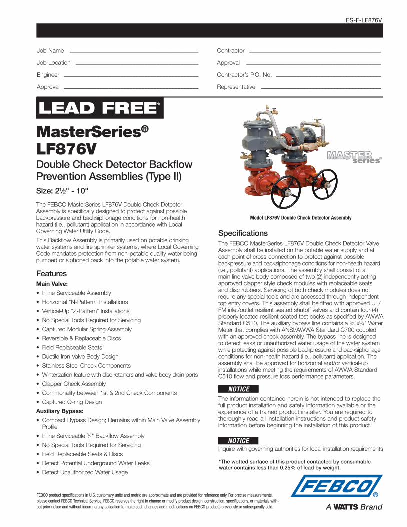
MaterialsBelow is a general materials list of the Model LF876V. All assemblies size 21⁄2" through 8" is similar in materials and construction. Please contact your local FEBCO Representative if you require further information.
Main Valve Body: Ductile iron Grade 65-45-12
Coating: Fusion epoxy coated internal and external AWWA C550-90
Shutoff Valves: OSY resilient wedge gate valve AWWA C515 (UL/FM)
Check Seats: Stainless Steel
Disc Holder: Stainless Steel
Elastomer Disc: Silicone
Spring: Stainless Steel
Clamp: AWWA C606
Approvals – Standards:• Approved by the Foundation for Cross-Connection Control
and Hydraulic Research at The University of Southern California [FCCCHR-USC]
• ASSE 1048 Listed
• **UL Classified [US & Canada]
• **FM Approved
• IAPMO/cUPC
• AWWA Standard C510 Compliant
• End Connections: Compliant to ASME B16.1 Class 125 & AWWA Class D Flange
**Assembly configured with UL/FM Approved OS&Y RW Gate Valves. Less gate valve assemblies are not UL/FM approved configurations.
Assembly Flow Orientation:Horizontal (N-Pattern 21⁄2" – 8") - Approved by FCCCHR-USC, ASSE, cULus, FM, IAPMO/cUPC
Vertical Up (Z-Pattern 21⁄2" – 8") - Approved by FCCCHR-USC, ASSE, cULus, FM, IAPMO/cUPC
Pressure - TemperatureMax. Working Pressure: 175psi (12.1 bar)
Min. Working Pressure: 10psi (0.7 bar)
Hydrostatic Test Pressure: 350psi (24.1 bar)
Hydrostatic Safety Pressure: 700psi (48.3 bar)
Temperature Range: 33°F - 140°F [0.5°C- 60°C] Continuous
1048 B64.5
** **
D
B
A
C
E
F
K* J
L
Test Cock #2
Test Cock #1
First Spring Assembly
First Check Assembly
Shutoff Valve #1
Test Cock #3
Second Check Assembly
Second Spring Assembly
Test Cock #4
Shutoff Valve #2
D
E
A
F
G
CH I

D
B
A
C
E
F
K* J
L
Test Cock #2
Test Cock #1
First Spring Assembly
First Check Assembly
Shutoff Valve #1
Test Cock #3
Second Check Assembly
Second Spring Assembly
Test Cock #4
Shutoff Valve #2
D
E
A
F
G
CH I
D
B
A
C
E
F
K* J
L
Test Cock #2
Test Cock #1
First Spring Assembly
First Check Assembly
Shutoff Valve #1
Test Cock #3
Second Check Assembly
Second Spring Assembly
Test Cock #4
Shutoff Valve #2
D
E
A
F
G
CH I
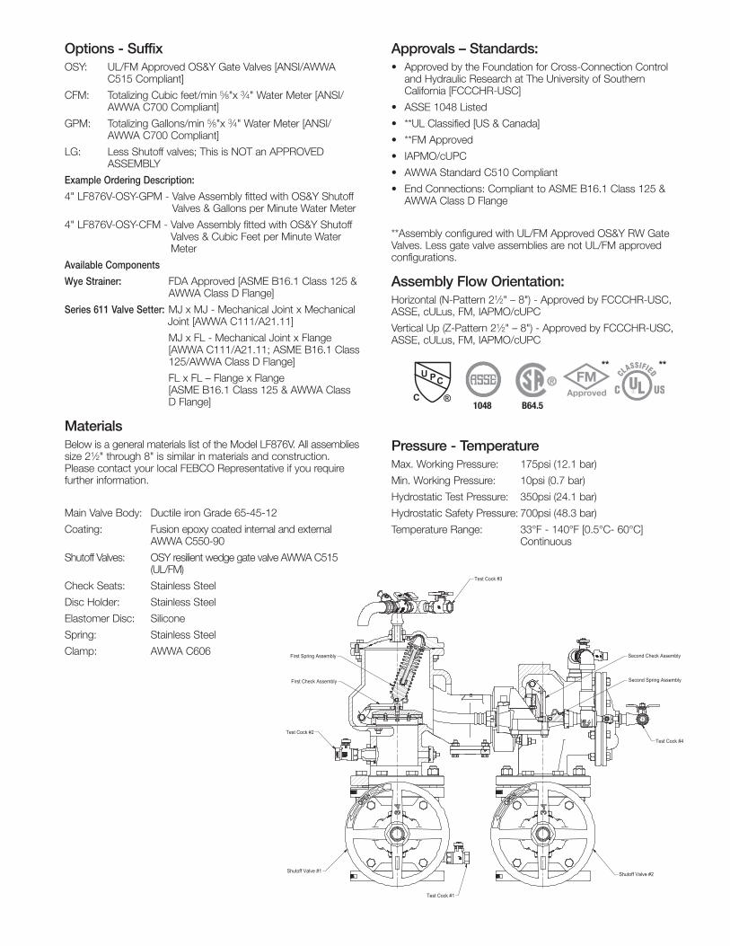
Model LF876V Standard Orientation (N-Pattern) Model LF876V Vertical Orientation (Z-Pattern)
Gate Valve Side View
Clearance
Note: The Series LF876V is shipped in the standard (N-Pattern) orientation as shown above.
L
K* J
E E
BI
G
F
F
A
AC CH
D D
Dimensions – WeightsSize: 21⁄2" - 10"
LF876V
Below are the nominal dimensions and physical weights for the Model LF876V size 21⁄2" through 10". Allowances must be made for normal manufacturing tolerances. Please visit our website to download a copy of this product’s installation instructions, or contact your local FEBCO Representative for more information.
SIZE DIMENSIONS WEIGHT**
A B C D E F G H I J K* L OSYin. in. mm in. mm in. mm in. mm in. mm in. mm in. mm in. mm in. mm in. mm in. mm in. mm lbs. kg.
21⁄2 291⁄8 740 121⁄2 318 61⁄4 159 251⁄4 642 171⁄2 445 135⁄8 346 271⁄4 692 51⁄2 140 111⁄8 283 31⁄2 89 163⁄8 416 111⁄2 292 216 98
3 291⁄8 740 121⁄2 318 61⁄4 159 253⁄4 654 173⁄4 451 141⁄8 359 281⁄4 718 51⁄2 140 111⁄8 283 33⁄4 95 221⁄4 565 111⁄2 292 242 110
4 311⁄8 791 14 356 7 178 273⁄4 705 183⁄4 476 151⁄2 394 31 787 6 152 111⁄8 283 41⁄2 114 231⁄4 591 13 330 347 157
6 353⁄4 908 16 406 8 203 323⁄4 831 221⁄8 562 185⁄8 473 371⁄4 946 71⁄4 184 121⁄2 316 51⁄2 140 301⁄8 765 13 330 529 240
8 403⁄4 1035 181⁄2 470 91⁄4 235 363⁄4 933 251⁄8 638 203⁄4 527 411⁄2 1054 81⁄2 216 14 356 63⁄4 172 373⁄4 959 141⁄2 368 827 375
10 461⁄4 1175 21 533 107⁄16 264 413⁄16 1047 281⁄8 714 2311⁄16 601 47 3/8 1202 9 5/8 244 1511⁄16 398 8 203 453⁄4 1162 131⁄8 333 1335 606
Notes:* Indicates nominal dimensions with OSY Gate Valves (Full Open Position)** Indicates weight of complete Backflow Assemblies with specified Gate Valves
ES-F-LF876V 1826 © 2018 FEBCO
USA: Tel: (800) 767-1234 • Fax: (800) 788-4491 • FEBCOonline.comCanada: Tel: (905) 332-4090 • Fax: (905) 332-7068 • FEBCOonline.ca
Latin America: (52) 81-1001-8600 • FEBCOonline.com
Pipe Support (furnished by customer)
for valve weight only.
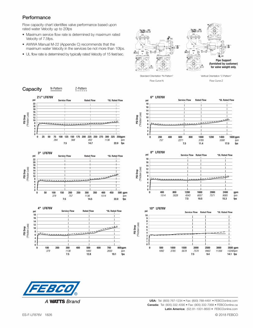
PerformanceFlow capacity chart identifies valve performance based upon rated water Velocity up to 20fps
• Maximum service flow rate is determined by maximum rated Velocity of 7.5fps.
• AWWA Manual M-22 (Appendix C) recommends that the maximum water Velocity in the services be not more than 10fps.
• UL flow rate is determined by typically rated Velocity of 15 feet/sec.
Standard Orientation “N-Pattern” Vertical Orientation “Z-Pattern”
Flow Curve N Flow Curve Z
D
B
A
C
E
F
K* J
L
Test Cock #2
Test Cock #1
First Spring Assembly
First Check Assembly
Shutoff Valve #1
Test Cock #3
Second Check Assembly
Second Spring Assembly
Test Cock #4
Shutoff Valve #2
D
E
A
F
G
CH I
21⁄2" LF876V
3" LF876V
4" LF876V
6" LF876V
8" LF876V
psi
22 20 18 16 14 12 10 8 6 4 2 0
psi
22 20 18 16 14 12 10 8 6 4 2 0
psi 18 16 14 12 10 8 6 4 2 0
psi 18 16 14 12 10 8 6 4 2 0
psi
18 16 14 12 10 8 6 4 2 0
0 25 50 75 100 125 150 175 200 225 250 275 300 325 350 gpm 284 568 852 1136 lpm 7.5 14.7 22.0 fps
0 50 100 150 200 250 300 350 400 450 500 gpm 379 757 1136 1514 lpm 7.5 14.5 22.0 fps
0 100 200 300 400 500 600 700 800 gpm 379 1136 1893 2650 lpm 7.5 12.8 19.1 fps
0 200 400 600 800 1000 1200 1400 1600 gpm 757 2271 3785 5300 lpm 7.5 11.4 17.0 fps
0 400 800 1200 1600 2000 2400 gpm 1514 3028 4543 6057 7571 9085 lpm 7.5 10.5 15.3 fps
Service Flow
Service Flow
Service Flow
Service Flow
Service Flow
Service Flow
Rated Flow
Rated Flow
Rated Flow
Rated Flow
Rated Flow
Rated Flow
*UL Rated Flow
*UL Rated Flow
*UL Rated Flow
*UL Rated Flow
*UL Rated Flow
*UL Rated Flow
N-Pattern Z-PatternCapacity
PSI D
rop
(*Fric
tion
Loss
)PS
I Dro
p (*F
rictio
n Lo
ss)
PSI D
rop
(*Fric
tion
Loss
)
PSI D
rop
(*Fric
tion
Loss
)PS
I Dro
p (*F
rictio
n Lo
ss)
10" LF876V
PSI D
rop
(*Fric
tion
Loss
)
psi
10 9 8 7 6 5 4 3 2
10
0 500 1000 1500 2000 2500 3000 3500 gpm 1892 3785 5678 7570 9463 11356 13248 lpm 7.5 9.4 14.1 fps