Embed Size (px)
DESCRIPTION
Amman TACC Operational Manual
Citation preview
The Hashemite Kingdom of Jordan
Civil Aviation Regulatory Commission
Air Navigation Services
Manual of Air Traffic Control Part II
MATC II
Terminal Area Control Centre "TACC"
Operational Procedures
Issued in accordance with Jordan Civil Aviation Regulations
On the Authority of the Chief Commissioner of the Civil Aviation
Regulatory Commission
Capt. Gabriel Sivzattian
Chief Commissioner
i
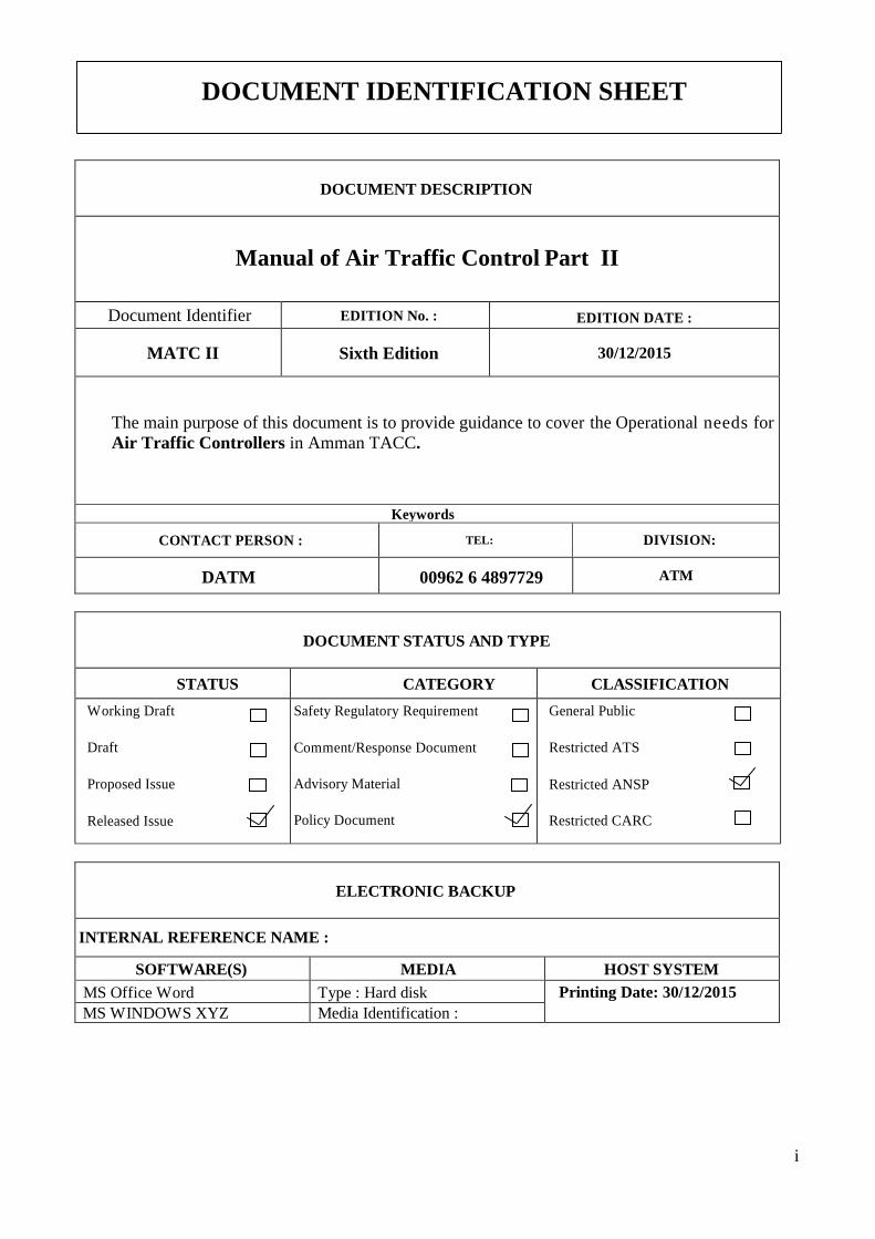
DOCUMENT IDENTIFICATION SHEET
DOCUMENT DESCRIPTION
Manual of Air Traffic Control Part II
EDITION DATE : EDITION No. : Document Identifier
30/12/2015 Sixth Edition MATC II
The main purpose of this document is to provide guidance to cover the Operational needs for
Air Traffic Controllers in Amman TACC.
Keywords
DIVISION: TEL: CONTACT PERSON :
ATM
00962 6 4897729
DATM
DOCUMENT STATUS AND TYPE
CLASSIFICATION CATEGORY STATUS
General Public
Restricted ATS
Restricted ANSP
Restricted CARC
Safety Regulatory Requirement
Comment/Response Document
Advisory Material
Policy Document
Working Draft
Draft
Proposed Issue
Released Issue
ELECTRONIC BACKUP
INTERNAL REFERENCE NAME :
HOST SYSTEM MEDIA SOFTWARE(S)
Printing Date: 30/12/2015 Type : Hard disk MS Office Word
Media Identification : MS WINDOWS XYZ
ii
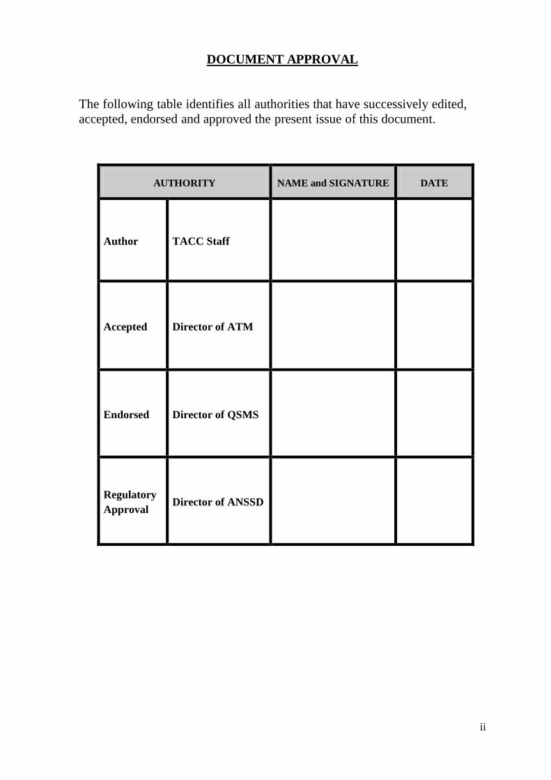
DOCUMENT APPROVAL
The following table identifies all authorities that have successively edited,
accepted, endorsed and approved the present issue of this document.
AUTHORITY NAME and SIGNATURE DATE
Author TACC Staff
Accepted Director of ATM
Endorsed Director of QSMS
Regulatory
Approval Director of ANSSD
iii
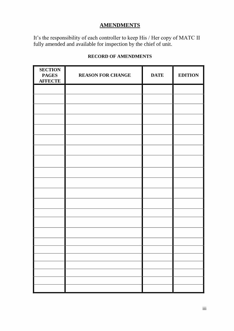
AMENDMENTS
It’s the responsibility of each controller to keep His / Her copy of MATC II
fully amended and available for inspection by the chief of unit.
RECORD OF AMENDMENTS
EDITION DATE REASON FOR CHANGE
SECTION
PAGES
AFFECTE
D
iv
TABLE OF CONTENTS
CHAPTER ONE : Introduction
1.1. Purpose:….. ...................................................................................................... 1
1.2. Layout:……. .................................................................................................... 1
1.3. General Instruction: ......................................................................................... 1
1.4. Symbols and abbreviations: ............................................................................ 3
CHAPTER TWO : Terminal Area Control Center
2.1. General Description: .................................................................................. 9
2.2. THALES RADAR Center: ........................................................................ 9
2.2.1. THALES RADAR System Description: .................................................... 9
2.2.2. THALES RADAR Control Sectorization: ................................................ 9
2.2.3. Sector Manning Level: .............................................................................. 11
2.2.4. Strip Layout: ............................................................................................... 12
2.3. INDRA RADAR CENTER: .................................................................... 12
2.3.1. INDRA RADAR System Description: ..................................................... 12
2.3.2. INDRA RADAR Control Sectorization: ................................................. 16
2.3.3. Sector Manning Level: .............................................................................. 18
2.3.4. Strip Layout: .............................................................................................. 20
2.4. Frequencies: .............................................................................................. 21
2.4.1. Navigation Aids Frequencies: ................................................................. 21
2.4.2. Voice Communication System " VCS " Frequencies: .......................... 22
2.5. Unit Administration: ................................................................................ 22
2.5.1. Responsibilities and Duties: ...................................................................... 22
2.5.2. Taking Over Watch: .................................................................................. 25
v
2.5.3. Leave: .......................................................................................................... 25
2.5.4. Control Room Discipline: ......................................................................... 26
2.5.5. Radio / Telephone Discipline: ................................................................... 26
2.5.6. Read-Back of clearances & Implementation: ......................................... 26
CHAPTER THREE : Deemed Separation
3.1. TMA Deemed Separation: ....................................................................... 30
3.2. En-route Deemed Separation: ................................................................. 30
3.2.1. ATS Route A 412: ....................................................................................... 30
3.2.2. ATS Route M 449: ...................................................................................... 31
3.2.3. ATS Route UB 411: ..................................................................................... 33
3.2.4. ATS Route UM 690:.................................................................................... 35
3.2.5. ATS Route G 662: ....................................................................................... 37
CHAPTER FOUR : RADAR Control
4.1. General: ..................................................................................................... 39
4.2. RADAR Identification : ........................................................................... 39
4.3. RADAR Separation Minima: .................................................................. 41
4.4. Mode C Verification and Errors: ........................................................... 41
4.5. SSR Codes: ................................................................................................ 42
4.5.1. General: ...................................................................................................... 42
4.5.2. SSR Code Failure: ..................................................................................... 42
4.5.3. Inbound SSR code assignment: ................................................................ 42
4.5.4. Over fly SSR code assignment: ................................................................ 43
4.5.5. Outbound SSR code assignment: ............................................................. 43
4.5.6. Domestic SSR Codes: ................................................................................ 43
vi
4.5.7. Regional SSR Codes assignment: ............................................................. 44
CHAPTER FIVE : TMA and AREA PROCEDURE
5.1. General: ..................................................................................................... 45
5.2. Outbound Traffic: .................................................................................... 45
5.3. Inbound Traffic: ....................................................................................... 46
5.4. PBN Procedure within AMMAN FIR " RNAV Procedure ": ............. 47
5.5. Holding Areas: .......................................................................................... 48
5.6 Charts:… .................................................................................................... 51
5.6.1 Minimum Vectoring Altitudes Chart: ..................................................... 51
5.6.2 Prohibited, Restricted and Danger Areas Chart: .................................. 52
5.6.3 En-route Chart: ......................................................................................... 53
CHAPTER SEVEN : Queen Alia Airport Procedures
7.1. General:….. ..................................................................................................... 64
7.2. Co-ordination Procedures : ........................................................................... 65
7.2.1. General and Flight planning: .................................................................. 65
7.2.2. Departure Flights Procedure: .................................................................. 65
7.2.3. Arrival Flights Procedure: ........................................................................ 66
7.2.4. RNAV Arrival Procedures: ...................................................................... 67
7.2.5. Visual Approach: ....................................................................................... 67
7.3. Landing Intervals: .................................................................................... 68
7.4. Runway Change: ...................................................................................... 69
7.5. Training Flights: ....................................................................................... 69
7.6. VFR and SVFR Procedure: ..................................................................... 70
7.7. Diversion Procedure: ............................................................................... 71
7.8. Emergency Procedures: ........................................................................... 71
vii
7.9. Fuel Dumping: .......................................................................................... 71
7.10. Miscellaneous Operations: ...................................................................... 72
7.11. Surveillance RADAR Approach " SRA ": ............................................ 72
7.12. Approach Procedures: ............................................................................. 77
7.12.1. Runway 26 L: ............................................................................................. 77
7.12.2. Runway 26 R: ............................................................................................. 78
7.12.3. Runway 08 L : ............................................................................................ 79
7.12.4. Runway 08 R: ............................................................................................. 79
CHAPTER EIGHT: King Hussein Aqaba Airport Procedures
8.1. General: ..................................................................................................... 81
8.2. Co-ordination Procedures : ..................................................................... 81
8.2.1. General and Flight planning: ................................................................... 81
8.2.2. Departure Flights Procedures: ................................................................. 81
8.2.3. Arrival Flights Procedures: ...................................................................... 82
8.2.4. Overflying Flights Procedures: ................................................................ 83
8.2.5. RNAV Arrival Procedures: ...................................................................... 83
8.2.6. Visual Approach: ....................................................................................... 83
8.3. Landing Intervals: .................................................................................... 84
8.4. Runway Change: ...................................................................................... 84
8.5. Training , VFR and SVFR Flights: ........................................................ 84
8.5.1. General : ................. ………………………………………………………84
8.5.2. Lateral limits: ............................................................................................. 84
8.5.3. Weather minima: ....................................................................................... 84
8.5.4. Responsibilities: ......................................................................................... 85
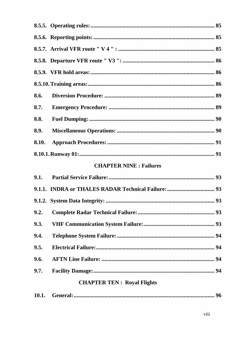
viii
8.5.5. Operating rules: ......................................................................................... 85
8.5.6. Reporting points: ....................................................................................... 85
8.5.7. Arrival VFR route " V 4 " : ..................................................................... 85
8.5.8. Departure VFR route " V3 ": .................................................................. 86
8.5.9. VFR hold areas: ......................................................................................... 86
8.5.10. Training areas: ........................................................................................... 86
8.6. Diversion Procedure: ............................................................................... 89
8.7. Emergency Procedure: ............................................................................ 89
8.8. Fuel Dumping: .......................................................................................... 90
8.9. Miscellaneous Operations: ...................................................................... 90
8.10. Approach Procedures: ............................................................................. 91
8.10.1. Runway 01: ................................................................................................. 91
CHAPTER NINE : Failures
9.1. Partial Service Failure: ............................................................................ 93
9.1.1. INDRA or THALES RADAR Technical Failure: .................................. 93
9.1.2. System Data Integrity: .............................................................................. 93
9.2. Complete Radar Technical Failure: ....................................................... 93
9.3. VHF Communication System Failure: ................................................... 93
9.4. Telephone System Failure: ...................................................................... 94
9.5. Electrical Failure: ..................................................................................... 94
9.6. AFTN Line Failure: ................................................................................. 94
9.7. Facility Damage: ....................................................................................... 94
CHAPTER TEN : Royal Flights
10.1. General: ..................................................................................................... 96
ix
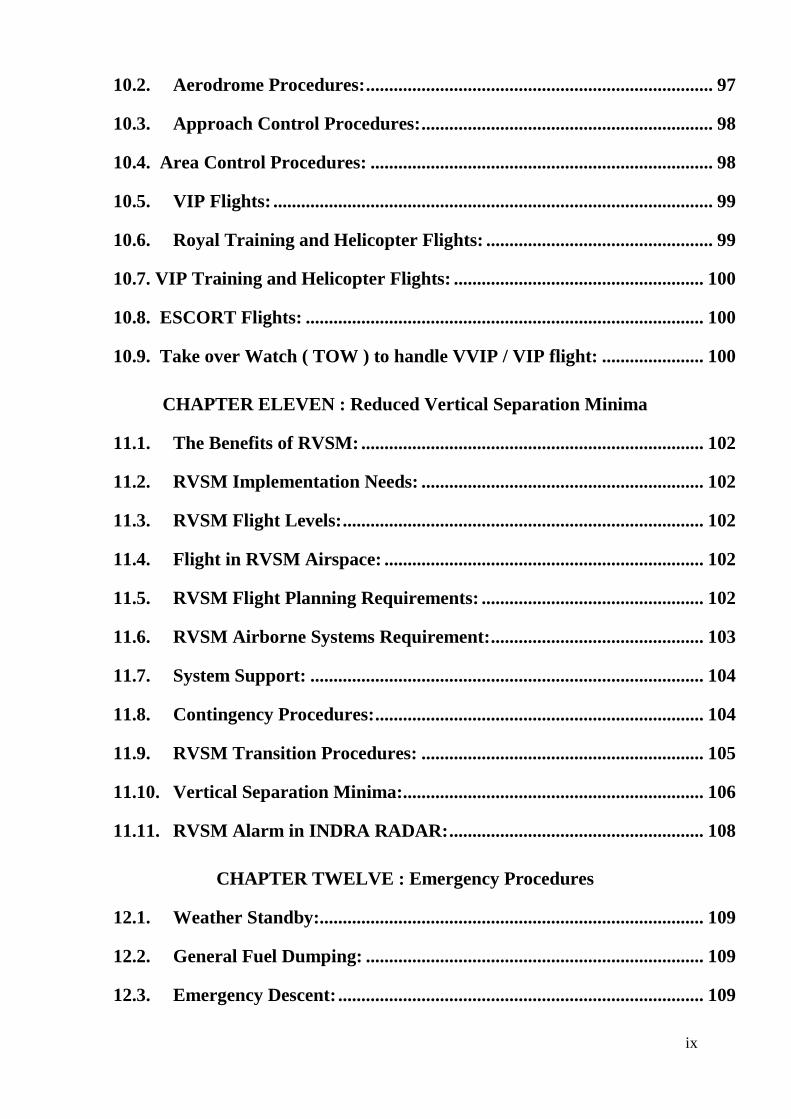
10.2. Aerodrome Procedures: ........................................................................... 97
10.3. Approach Control Procedures: ............................................................... 98
10.4. Area Control Procedures: .......................................................................... 98
10.5. VIP Flights: ............................................................................................... 99
10.6. Royal Training and Helicopter Flights: ................................................. 99
10.7. VIP Training and Helicopter Flights: ...................................................... 100
10.8. ESCORT Flights: ...................................................................................... 100
10.9. Take over Watch ( TOW ) to handle VVIP / VIP flight: ...................... 100
CHAPTER ELEVEN : Reduced Vertical Separation Minima
11.1. The Benefits of RVSM: .......................................................................... 102
11.2. RVSM Implementation Needs: ............................................................. 102
11.3. RVSM Flight Levels: .............................................................................. 102
11.4. Flight in RVSM Airspace: ..................................................................... 102
11.5. RVSM Flight Planning Requirements: ................................................ 102
11.6. RVSM Airborne Systems Requirement: .............................................. 103
11.7. System Support: ..................................................................................... 104
11.8. Contingency Procedures: ....................................................................... 104
11.9. RVSM Transition Procedures: ............................................................. 105
11.10. Vertical Separation Minima:................................................................. 106
11.11. RVSM Alarm in INDRA RADAR: ....................................................... 108
CHAPTER TWELVE : Emergency Procedures
12.1. Weather Standby:................................................................................... 109
12.2. General Fuel Dumping: ......................................................................... 109
12.3. Emergency Descent: ............................................................................... 109
x
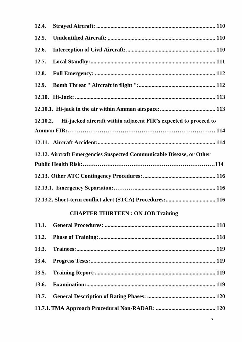
12.4. Strayed Aircraft: .................................................................................... 110
12.5. Unidentified Aircraft: ............................................................................ 110
12.6. Interception of Civil Aircraft: ............................................................... 110
12.7. Local Standby: ........................................................................................ 111
12.8. Full Emergency: ..................................................................................... 112
12.9. Bomb Threat " Aircraft in flight ": ...................................................... 112
12.10. Hi-Jack: ................................................................................................... 113
12.10.1. Hi-jack in the air within Amman airspace: ....................................... 113
12.10.2. Hi-jacked aircraft within adjacent FIR’s expected to proceed to
Amman FIR:…………………………………………………………………… 114
12.11. Aircraft Accident:................................................................................... 114
12.12. Aircraft Emergencies Suspected Communicable Disease, or Other
Public Health Risk:…………….………………………………………………114
12.13. Other ATC Contingency Procedures: ................................................... 116
12.13.1. Emergency Separation:………. .......................................................... 116
12.13.2. Short-term conflict alert (STCA) Procedures: ................................... 116
CHAPTER THIRTEEN : ON JOB Training
13.1. General Procedures: .............................................................................. 118
13.2. Phase of Training: .................................................................................. 118
13.3. Trainees: .................................................................................................. 119
13.4. Progress Tests: ........................................................................................ 119
13.5. Training Report:..................................................................................... 119
13.6. Examination: ........................................................................................... 119
13.7. General Description of Rating Phases: ................................................ 120
13.7.1. TMA Approach Procedural Non-RADAR: .......................................... 120
xi
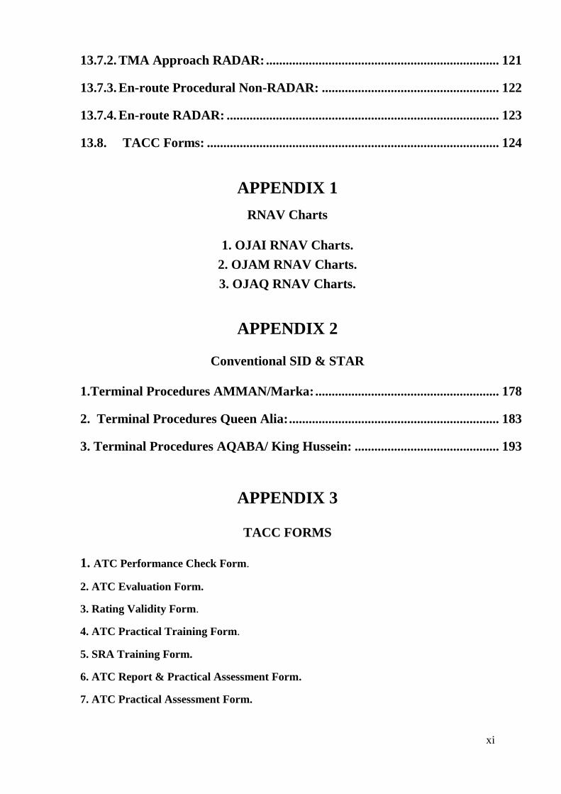
13.7.2. TMA Approach RADAR: ....................................................................... 121
13.7.3. En-route Procedural Non-RADAR: ...................................................... 122
13.7.4. En-route RADAR: ................................................................................... 123
13.8. TACC Forms: ......................................................................................... 124
APPENDIX 1
RNAV Charts
1. OJAI RNAV Charts.
2. OJAM RNAV Charts.
3. OJAQ RNAV Charts.
APPENDIX 2
Conventional SID & STAR
1.Terminal Procedures AMMAN/Marka: ........................................................ 178
2. Terminal Procedures Queen Alia: ................................................................ 183
3. Terminal Procedures AQABA/ King Hussein: ............................................ 193
APPENDIX 3
TACC FORMS
1. ATC Performance Check Form.
2. ATC Evaluation Form.
3. Rating Validity Form.
4. ATC Practical Training Form.
5. SRA Training Form.
6. ATC Report & Practical Assessment Form.
7. ATC Practical Assessment Form.
xii
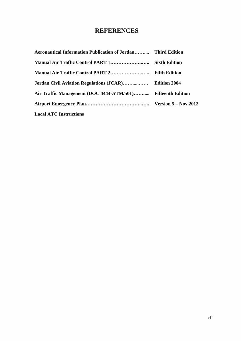
REFERENCES
Aeronautical Information Publication of Jordan…….... Third Edition
Manual Air Traffic Control PART 1………………..….. Sixth Edition
Manual Air Traffic Control PART 2………………..….. Fifth Edition
Jordan Civil Aviation Regulations (JCAR)…….....…… Edition 2004
Air Traffic Management (DOC 4444-ATM/501)……..... Fifteenth Edition
Airport Emergency Plan……………………………..….. Version 5 – Nov.2012
Local ATC Instructions

CHAPTER ONE
INTRODUCTION
MATC 2 INTRODUCTION CHAPTER 1
EDITION No. 6 Effective Date: 30/12/2015 Page 1
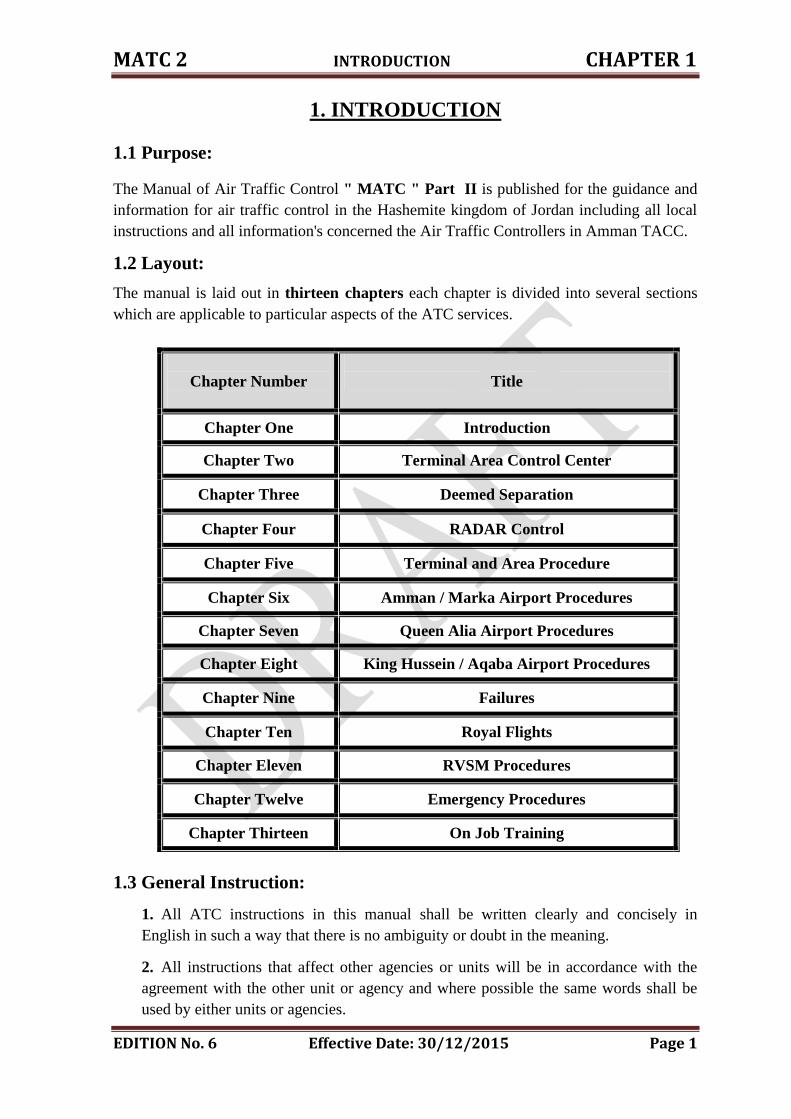
1. INTRODUCTION
1.1 Purpose:
The Manual of Air Traffic Control " MATC " Part II is published for the guidance and
information for air traffic control in the Hashemite kingdom of Jordan including all local
instructions and all information's concerned the Air Traffic Controllers in Amman TACC.
1.2 Layout:
The manual is laid out in thirteen chapters each chapter is divided into several sections
which are applicable to particular aspects of the ATC services.
1.3 General Instruction:
1. All ATC instructions in this manual shall be written clearly and concisely in
English in such a way that there is no ambiguity or doubt in the meaning.
2. All instructions that affect other agencies or units will be in accordance with the
agreement with the other unit or agency and where possible the same words shall be
used by either units or agencies.
Chapter Number
Title
Chapter One Introduction
Chapter Two Terminal Area Control Center
Chapter Three Deemed Separation
Chapter Four RADAR Control
Chapter Five Terminal and Area Procedure
Chapter Six Amman / Marka Airport Procedures
Chapter Seven Queen Alia Airport Procedures
Chapter Eight King Hussein / Aqaba Airport Procedures
Chapter Nine Failures
Chapter Ten Royal Flights
Chapter Eleven RVSM Procedures
Chapter Twelve Emergency Procedures
Chapter Thirteen On Job Training
MATC 2 INTRODUCTION CHAPTER 1
EDITION No. 6 Effective Date: 30/12/2015 Page 2
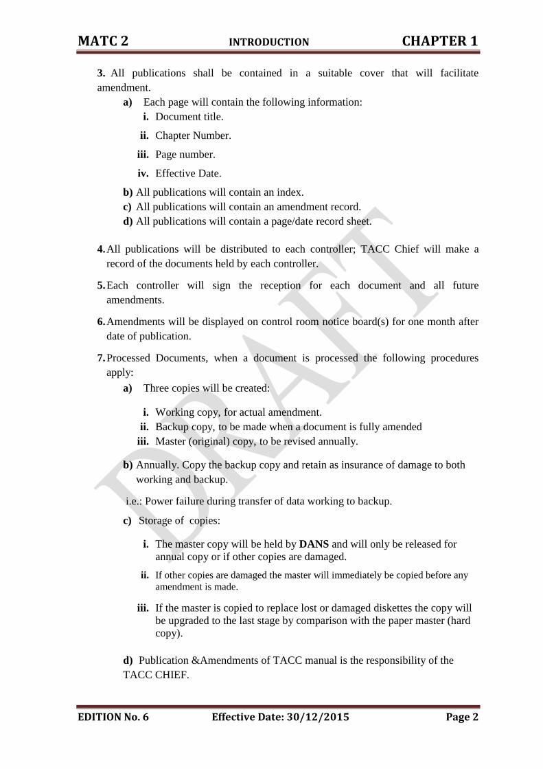
3. All publications shall be contained in a suitable cover that will facilitate
amendment.
a) Each page will contain the following information:
i. Document title.
ii. Chapter Number.
iii. Page number.
iv. Effective Date.
b) All publications will contain an index.
c) All publications will contain an amendment record.
d) All publications will contain a page/date record sheet.
4. All publications will be distributed to each controller; TACC Chief will make a
record of the documents held by each controller.
5. Each controller will sign the reception for each document and all future
amendments.
6. Amendments will be displayed on control room notice board(s) for one month after
date of publication.
7. Processed Documents, when a document is processed the following procedures
apply:
a) Three copies will be created:
i. Working copy, for actual amendment.
ii. Backup copy, to be made when a document is fully amended
iii. Master (original) copy, to be revised annually.
b) Annually. Copy the backup copy and retain as insurance of damage to both
working and backup.
i.e.: Power failure during transfer of data working to backup.
c) Storage of copies:
i. The master copy will be held by DANS and will only be released for
annual copy or if other copies are damaged.
ii. If other copies are damaged the master will immediately be copied before any
amendment is made.
iii. If the master is copied to replace lost or damaged diskettes the copy will
be upgraded to the last stage by comparison with the paper master (hard
copy).
d) Publication &Amendments of TACC manual is the responsibility of the
TACC CHIEF.
MATC 2 INTRODUCTION CHAPTER 1
EDITION No. 6 Effective Date: 30/12/2015 Page 3
i. All amendments will be submitted to DANS for his approval.
ii. The purpose of approval is to ensure that the procedures at TACC meet
the general standard and policy of the CARC.
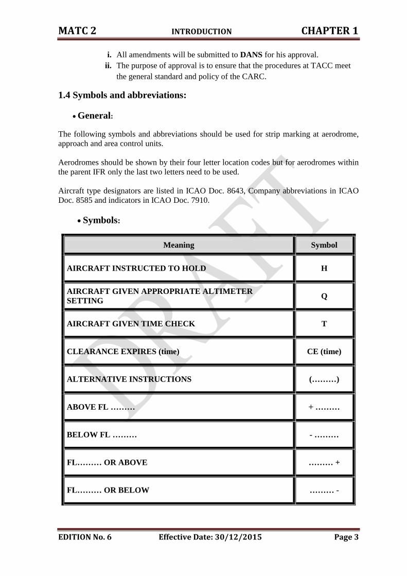
1.4 Symbols and abbreviations:
General:
The following symbols and abbreviations should be used for strip marking at aerodrome,
approach and area control units.
Aerodromes should be shown by their four letter location codes but for aerodromes within
the parent IFR only the last two letters need to be used.
Aircraft type designators are listed in ICAO Doc. 8643, Company abbreviations in ICAO
Doc. 8585 and indicators in ICAO Doc. 7910.
Symbols:
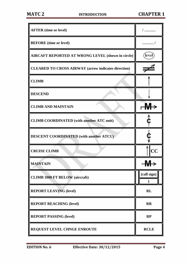
Meaning Symbol
AIRCRAFT INSTRUCTED TO HOLD H
AIRCRAFT GIVEN APPROPRIATE ALTIMETER
SETTING Q
AIRCRAFT GIVEN TIME CHECK T
CLEARANCE EXPIRES (time) CE (time)
ALTERNATIVE INSTRUCTIONS (………)
ABOVE FL ……… + ………
BELOW FL ……… - ………
FL……… OR ABOVE ……… +
FL……… OR BELOW ……… -
MATC 2 INTRODUCTION CHAPTER 1
EDITION No. 6 Effective Date: 30/12/2015 Page 4
AFTER (time or level) / ………
BEFORE (time or level) ……… /
AIRCAFT REPORTED AT WRONG LEVEL (shown in circle)
CLEARED TO CROSS AIRWAY (arrow indicates direction)
CLIMB
DESCEND
CLIMB AND MAINTAIN
CLIMB COORDINATED (with another ATC unit)
DESCENT COORDINATED (with another ATCU)
CRUISE CLIMB
CC
MAINTAIN
CLIMB 1000 FT BELOW (aircraft)
(call sign)
1
REPORT LEAVING (level) RL
REPORT REACHING (level) RR
REPORT PASSING (level) RP
REQUEST LEVEL CHNGE ENROUTE RCLE
MATC 2 INTRODUCTION CHAPTER 1
EDITION No. 6 Effective Date: 30/12/2015 Page 5
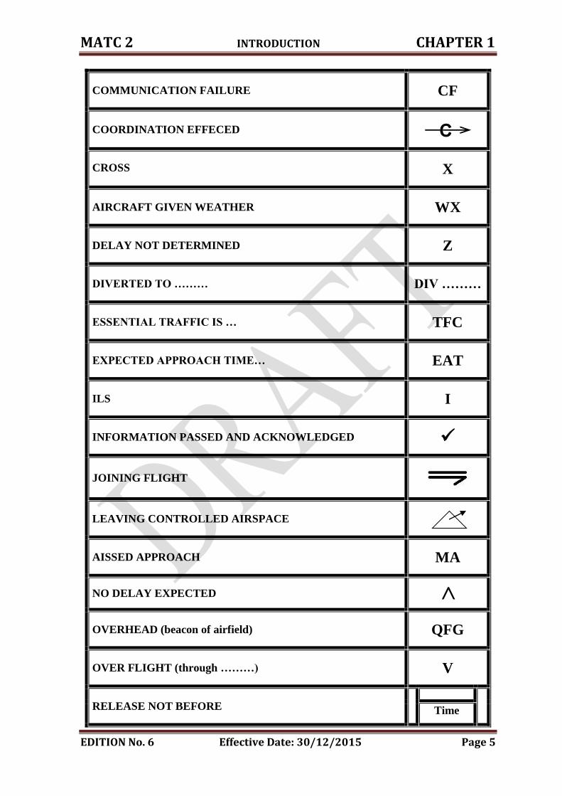
COMMUNICATION FAILURE CF
COORDINATION EFFECED
CROSS
X
AIRCRAFT GIVEN WEATHER WX
DELAY NOT DETERMINED Z
DIVERTED TO ……… DIV ………
ESSENTIAL TRAFFIC IS … TFC
EXPECTED APPROACH TIME… EAT
ILS I
INFORMATION PASSED AND ACKNOWLEDGED
JOINING FLIGHT
LEAVING CONTROLLED AIRSPACE
AISSED APPROACH MA
NO DELAY EXPECTED >
OVERHEAD (beacon of airfield) QFG
OVER FLIGHT (through ………) V
RELEASE NOT BEFORE
Time
MATC 2 INTRODUCTION CHAPTER 1
EDITION No. 6 Effective Date: 30/12/2015 Page 6
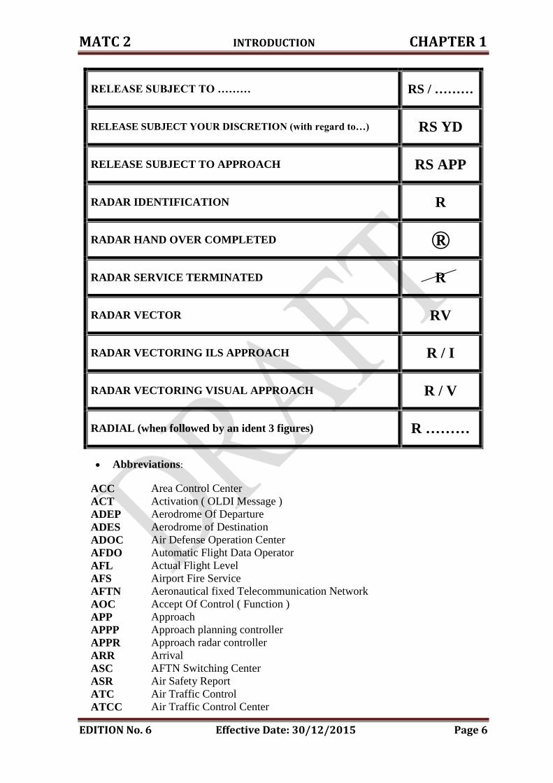
RELEASE SUBJECT TO ……… RS / ………
RELEASE SUBJECT YOUR DISCRETION (with regard to…) RS YD
RELEASE SUBJECT TO APPROACH RS APP
RADAR IDENTIFICATION R
RADAR HAND OVER COMPLETED ®
RADAR SERVICE TERMINATED R
RADAR VECTOR RV
RADAR VECTORING ILS APPROACH R / I
RADAR VECTORING VISUAL APPROACH R / V
RADIAL (when followed by an ident 3 figures) R ………
Abbreviations:
ACC Area Control Center
ACT Activation ( OLDI Message )
ADEP Aerodrome Of Departure
ADES Aerodrome of Destination
ADOC Air Defense Operation Center
AFDO Automatic Flight Data Operator
AFL Actual Flight Level
AFS Airport Fire Service
AFTN Aeronautical fixed Telecommunication Network
AOC Accept Of Control ( Function )
APP Approach
APPP Approach planning controller
APPR Approach radar controller
ARR Arrival
ASC AFTN Switching Center
ASR Air Safety Report
ATC Air Traffic Control
ATCC Air Traffic Control Center
MATC 2 INTRODUCTION CHAPTER 1
EDITION No. 6 Effective Date: 30/12/2015 Page 7
ATCO Air Traffic Control Officer
ATIS Automatic Terminal Information Service
ATM Air Traffic Management
ATS Air Traffic Services
BPN Boundary Point : Entry Point
BPX Boundary Point : Exit Point
BRS Built-In Radio Switch
CAS Controlled Air Space
CATC Chief of Air Traffic Control
CD Civil Defense
CFL Cleared Flight Level
CH Channel Check Message ( AFTN )
CIDIN Common ICAO Data Interchange Network
CLM Claim
CSCI Computer Software Configuration Item
CTACC Chief Of Terminal Area Control Center
DAIW Danger Area Infringement Warning
DANS Director Of Air Navigation Services
DATM Duty Air Traffics Management
DCT Direct Route
DEC Digital Equipment Corporation
DEP Departure
DLA Delay
EET Estimated Elapsed Time
EST Estimated Flight Plan ( Function )
ERVCC Emergency Radio Voice Communication Console
ETA Estimated Time Of Arrival
ETB Estimated Time Boundary
ETD Estimated Time Of Departure
ETN Estimated Time Next Point
ETO Estimated Time Of Over flight
ETX Estimated Time Of Exit Point
FDO Flight Data Operator
FDP Flight Data Processor
FIR Flight Information Region
FL Flight Level In Hundreds Of Feet
FPL Flight Plan
FPPS Flight Plan Processing System
FPS Flight Progress Strip
GMC Ground Movement Control
HMI Human Machine Interface
HND Hand-over (Function )
ICAO International Civil Aviation Organization
IFR Instrumental Flight Rules
KBD Keyboard
LAM Logical Acknowledgement Message ( OLDI)
LAN Local Area Network
LOA Letter of agreement
LPL Local Flight Plan
MFT Multi-Function Terminal
MATC 2 INTRODUCTION CHAPTER 1
EDITION No. 6 Effective Date: 30/12/2015 Page 8
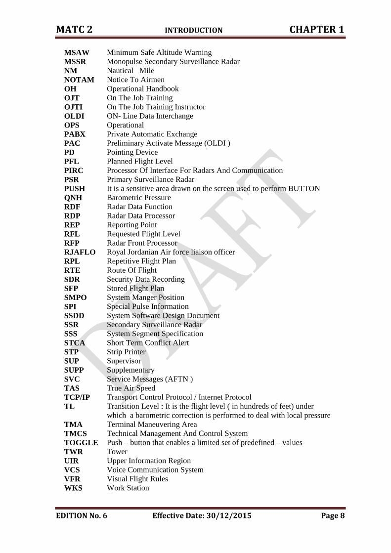
MSAW Minimum Safe Altitude Warning
MSSR Monopulse Secondary Surveillance Radar
NM Nautical Mile
NOTAM Notice To Airmen
OH Operational Handbook
OJT On The Job Training
OJTI On The Job Training Instructor
OLDI ON- Line Data Interchange
OPS Operational
PABX Private Automatic Exchange
PAC Preliminary Activate Message (OLDI )
PD Pointing Device
PFL Planned Flight Level
PIRC Processor Of Interface For Radars And Communication
PSR Primary Surveillance Radar
PUSH It is a sensitive area drawn on the screen used to perform BUTTON
QNH Barometric Pressure
RDF Radar Data Function
RDP Radar Data Processor
REP Reporting Point
RFL Requested Flight Level
RFP Radar Front Processor
RJAFLO Royal Jordanian Air force liaison officer
RPL Repetitive Flight Plan
RTE Route Of Flight
SDR Security Data Recording
SFP Stored Flight Plan
SMPO System Manger Position
SPI Special Pulse Information
SSDD System Software Design Document
SSR Secondary Surveillance Radar
SSS System Segment Specification
STCA Short Term Conflict Alert
STP Strip Printer
SUP Supervisor
SUPP Supplementary
SVC Service Messages (AFTN )
TAS True Air Speed
TCP/IP Transport Control Protocol / Internet Protocol
TL Transition Level : It is the flight level ( in hundreds of feet) under
which a barometric correction is performed to deal with local pressure
TMA Terminal Maneuvering Area
TMCS Technical Management And Control System
TOGGLE Push – button that enables a limited set of predefined – values
TWR Tower
UIR Upper Information Region
VCS Voice Communication System
VFR Visual Flight Rules
WKS Work Station
CHAPTER TWO
TERMINAL AREA CONTROL CENTER
MATC 2 Terminal Area Control Center CHAPTER 2
EDITION No. 6 Effective Date: 30/12/2015 Page 9
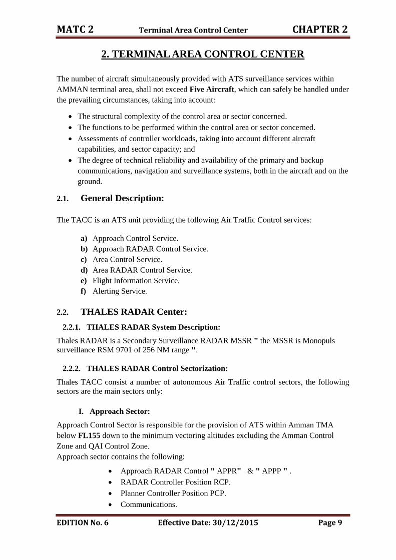
2. TERMINAL AREA CONTROL CENTER
The number of aircraft simultaneously provided with ATS surveillance services within
AMMAN terminal area, shall not exceed Five Aircraft, which can safely be handled under
the prevailing circumstances, taking into account:
The structural complexity of the control area or sector concerned.
The functions to be performed within the control area or sector concerned.
Assessments of controller workloads, taking into account different aircraft
capabilities, and sector capacity; and
The degree of technical reliability and availability of the primary and backup
communications, navigation and surveillance systems, both in the aircraft and on the
ground.
2.1. General Description:
The TACC is an ATS unit providing the following Air Traffic Control services:
a) Approach Control Service.
b) Approach RADAR Control Service.
c) Area Control Service.
d) Area RADAR Control Service.
e) Flight Information Service.
f) Alerting Service.
2.2. THALES RADAR Center:
2.2.1. THALES RADAR System Description:
Thales RADAR is a Secondary Surveillance RADAR MSSR " the MSSR is Monopuls
surveillance RSM 9701 of 256 NM range ".
2.2.2. THALES RADAR Control Sectorization:
Thales TACC consist a number of autonomous Air Traffic control sectors, the following
sectors are the main sectors only:
I. Approach Sector:
Approach Control Sector is responsible for the provision of ATS within Amman TMA
below FL155 down to the minimum vectoring altitudes excluding the Amman Control
Zone and QAI Control Zone.
Approach sector contains the following:
Approach RADAR Control " APPR " & " APPP " .
RADAR Controller Position RCP.
Planner Controller Position PCP.
Communications.

MATC 2 Terminal Area Control Center CHAPTER 2
EDITION No. 6 Effective Date: 30/12/2015 Page 10
Navigation aids Monitor.
Emergency Radio SELEX.
Recording system RC 2000.
MET displays.
II. West Sector:
The West Sector is responsible for all controlled airspace within Amman FIR West
of the Western boundary of UR785 from its intersection with Amman FIR
boundary at ZELAF to RASLI, and the Western boundary of Jordan political
boundary excluding Amman TMA and Aqaba Approach above FL160, the West
sector contains the following:
West Sector RADAR Control " WSRC " & " WSPC " .
RADAR Controller Position RCP.
Planner Controller Position PCP.
Communications.
Emergency Radio SELEX.
Recording system RC2000.
MET displays.
III. East Sector:
The East Upper Sector is responsible for all controlled airspace within Amman FIR
East of the Western Boundary of UR785 from its intersection with Amman FIR
boundary at OTILA to SOKAN or NAMBO then ZELAF to RASLI, and within
Jordan political boundaries, the East sector contains the following:
East Sector RADAR Control " ESRC " & " ESPC " .
RADAR Controller Position RCP.
Planner Controller Position PCP.
Communications.
Emergency Radio SELEX.
Recording system RC2000.
MET displays.
IV. TACC Supervisor:
Operational Supervisor position with the capability of the following special
functions:
Modification QNH, TL & QFU.
Sectorization.
Information pages.
Alert area selection.
MET display " radio and telephones communication " .
MATC 2 Terminal Area Control Center CHAPTER 2
EDITION No. 6 Effective Date: 30/12/2015 Page 11
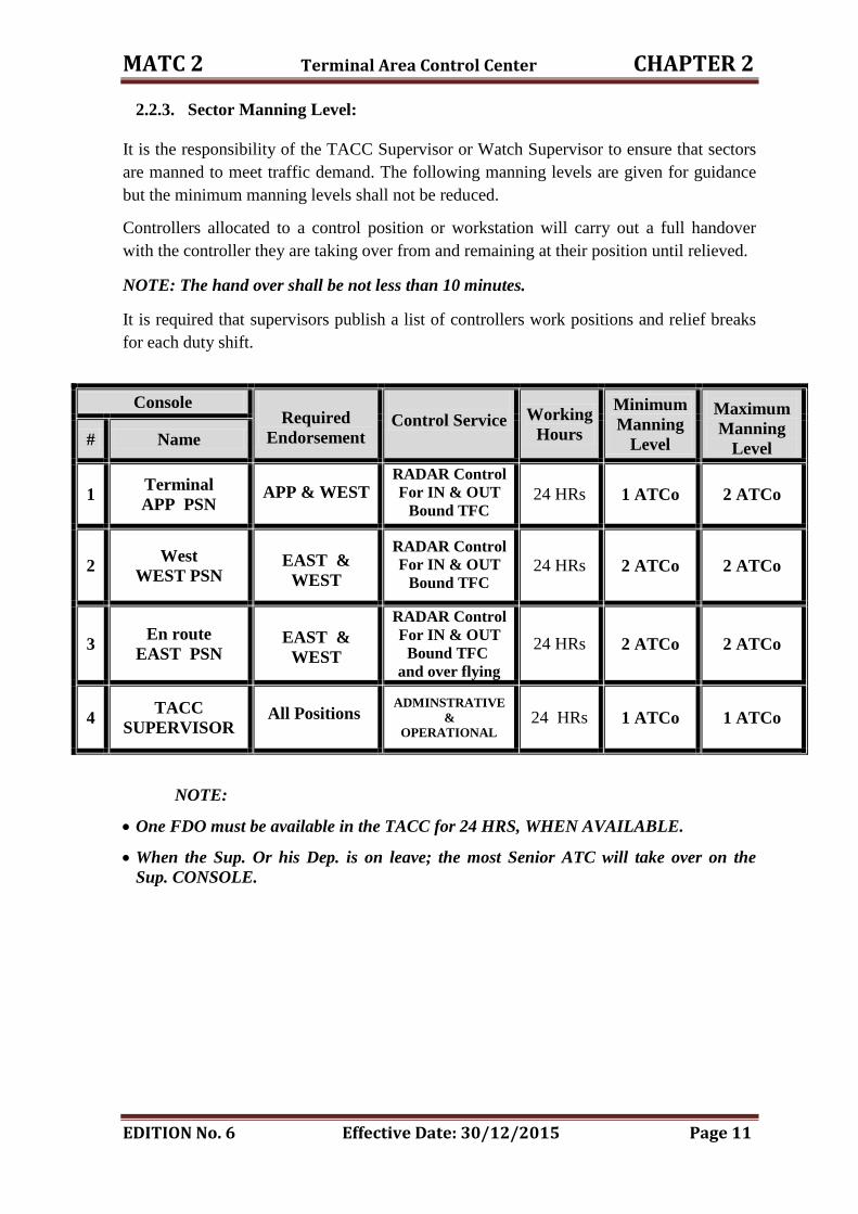
2.2.3. Sector Manning Level:
It is the responsibility of the TACC Supervisor or Watch Supervisor to ensure that sectors
are manned to meet traffic demand. The following manning levels are given for guidance
but the minimum manning levels shall not be reduced.
Controllers allocated to a control position or workstation will carry out a full handover
with the controller they are taking over from and remaining at their position until relieved.
NOTE: The hand over shall be not less than 10 minutes.
It is required that supervisors publish a list of controllers work positions and relief breaks
for each duty shift.
Console Required
Endorsement
Control Service Working
Hours
Minimum
Manning
Level
Maximum
Manning
Level # Name
1 Terminal
APP PSN APP & WEST
RADAR Control For IN & OUT
Bound TFC 24 HRs 1 ATCo 2 ATCo
2 West
WEST PSN
EAST &
WEST
RADAR Control For IN & OUT
Bound TFC 24 HRs 2 ATCo 2 ATCo
3 En route
EAST PSN
EAST &
WEST
RADAR Control For IN & OUT
Bound TFC and over flying
24 HRs 2 ATCo 2 ATCo
4 TACC
SUPERVISOR
All Positions
ADMINSTRATIVE &
OPERATIONAL 24 HRs 1 ATCo 1 ATCo
NOTE:
One FDO must be available in the TACC for 24 HRS, WHEN AVAILABLE.
When the Sup. Or his Dep. is on leave; the most Senior ATC will take over on the
Sup. CONSOLE.
MATC 2 Terminal Area Control Center CHAPTER 2
EDITION No. 6 Effective Date: 30/12/2015 Page 12
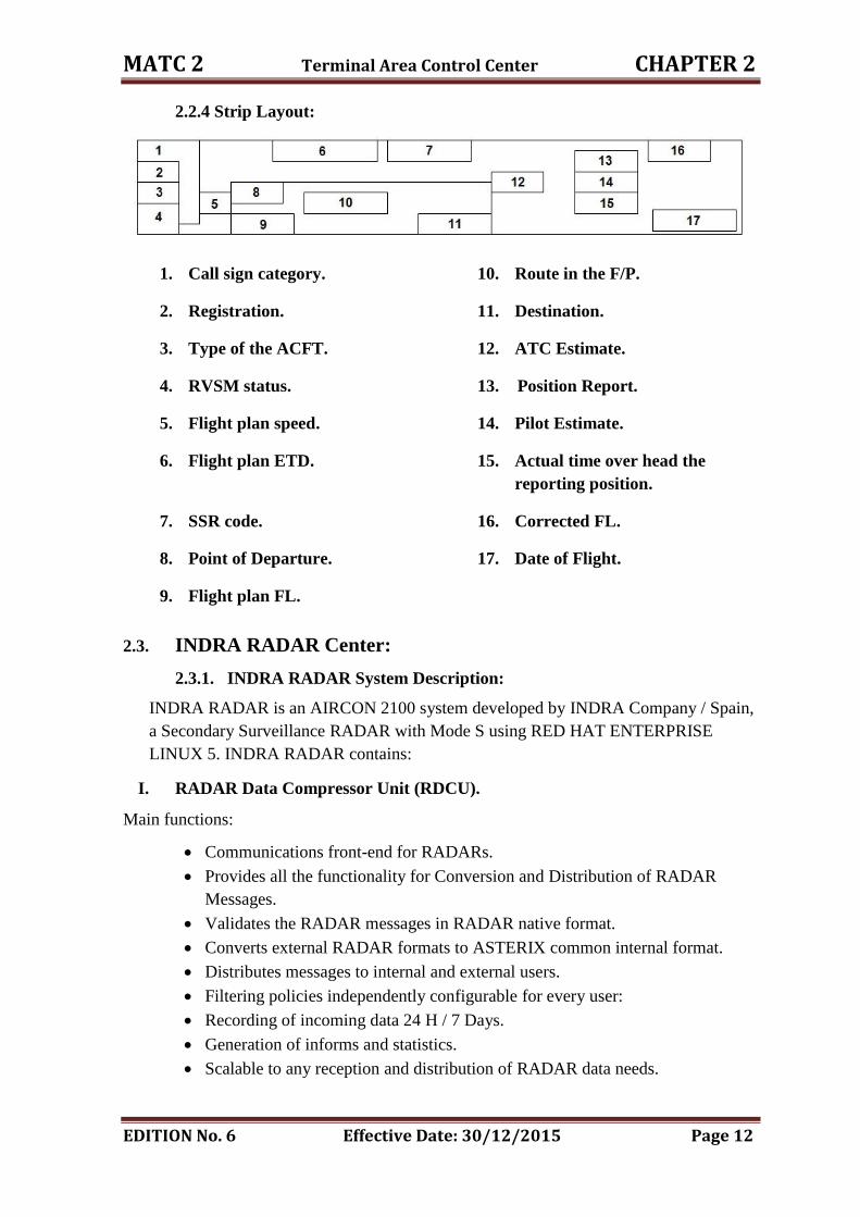
2.2.4 Strip Layout:
1. Call sign category. 10. Route in the F/P.
2. Registration. 11. Destination.
3. Type of the ACFT. 12. ATC Estimate.
4. RVSM status. 13. Position Report.
5. Flight plan speed. 14. Pilot Estimate.
6. Flight plan ETD. 15. Actual time over head the
reporting position.
7. SSR code. 16. Corrected FL.
8. Point of Departure. 17. Date of Flight.
9. Flight plan FL.
2.3. INDRA RADAR Center:
2.3.1. INDRA RADAR System Description:
INDRA RADAR is an AIRCON 2100 system developed by INDRA Company / Spain,
a Secondary Surveillance RADAR with Mode S using RED HAT ENTERPRISE
LINUX 5. INDRA RADAR contains:
I. RADAR Data Compressor Unit (RDCU).
Main functions:
Communications front-end for RADARs.
Provides all the functionality for Conversion and Distribution of RADAR
Messages.
Validates the RADAR messages in RADAR native format.
Converts external RADAR formats to ASTERIX common internal format.
Distributes messages to internal and external users.
Filtering policies independently configurable for every user:
Recording of incoming data 24 H / 7 Days.
Generation of informs and statistics.
Scalable to any reception and distribution of RADAR data needs.
MATC 2 Terminal Area Control Center CHAPTER 2
EDITION No. 6 Effective Date: 30/12/2015 Page 13
II. Surveillance Data Processor (SDP).
Main functions:
Two different systems dual redundant SDP.
Both having been developed independently.
Both with equivalent functionality and performances.
Immediate Switchover from Primary SDP to Fallback SDP as well as between
Active and Standby within these SDPs and vice versa without any loss/
discontinuity in the air traffic situation picture.
Sensor data input processing and Real-time quality control.
Mono-sensor and Multi-sensor tracking.
Weather data processing.
Distribution of System Tracks to internal users.
Redundancy and fall back.
III. Flight Data Processor (FDP).
Main functions:
Reception and processing of AFTN / ADEXP messages.
Validation and processing of flight plans entered from the AFTN / IFPS or
from the controller workstations.
Management of flight plan "FPL" database and support of operator's actions.
Analysis of flight plan routes and calculation of flight trajectory and estimated
times.
Assignment of SSR codes "domestic flights", SID and STAR procedures.
Distribution of flight plans to the SDP, EFSS, controller workstation, strip
printers and adjacent ATC centers.
Handoff management.
Inter-centers coordination "OLDI, AIDC".
Management of the SFPL and RPL databases.
Issue and transmission of AFTN messages.
Update of flight plan estimates provided by the RADAR Data Processing.
Detection and identification of potential conflicts in standard separations of
flight plans: Medium Term Conflict Alert "MTCA".
Forecasting of potential intrusion into restricted areas.
Flow Planning.
Meteorological and Aeronautical Information management.
Recording of flight plans for further use in billing calculation and statistics.
MATC 2 Terminal Area Control Center CHAPTER 2
EDITION No. 6 Effective Date: 30/12/2015 Page 14
Validation and processing of NOTAMs entered from the AFTN or from
selected workstations.
Management of restricted areas.
Identification of flight plans as "RVSM equipped flight".
Identification of flight plans as "8.33 equipped flight".
IV. Data Recording Facility (DRF).
Main functions:
The last 24 hours data is recorded in the local SDD disk, being available for
immediate playback.
DRF central servers carry out global recording of RADAR.
DRF saves recorded data in local disk and DDS tapes, and allows the export to
other external devices.
Playback can be affected in any non-sectorized SDD.
Voice and Data are synchronized for playback.
Passive and Interactive playback toggle.
V. Situation Data Display (SDD).
Main functions:
Display of system tracks, RADAR plots and weather contours.
Display of DF information.
Display of Flight Plan lists.
Display and graphic modification of Flight Plan route.
Display of coast and hold lists.
Display of aeronautical maps and restricted areas.
Display of graphic tools "RBLs, local maps".
Display of auxiliary information "time, QNH, controlled sectors, sector
assignation to other CWP, etc".
Display of MET information.
Access to flight plan database "Retrieve, Creation, Modification,
Cancellation".
Support of controller‟s actions "clearances, ATD, ARR, EST".
Save/Restore of user preferences.
Control features of the local display "filters, off centering, range".
Printout of flight strips "for non strip-less environments" and flight plan lists.
MATC 2 Terminal Area Control Center CHAPTER 2
EDITION No. 6 Effective Date: 30/12/2015 Page 15
Display of Short Term Conflict Alerts "STCA", Minimum Safe Altitude
Warnings "MSAW", Restricted Area Warnings, CFL Conformance Alarms
"CLAM", Area Proximity Warning "APW", Route Adherence Monitoring
"RAM".
Display of conflict situations "MTCA" and traffic extrapolated to the future.
Track location by SSR code Call sign, Airport, Fix point, Lat/Long coordinates
or mouse location input. And last position of a lost track.
3D Filter and SSR code filter.
Autonomous mono RADAR tracking in case of failure of the SDP servers
"By-pass mode".
Local recording and playback in the same SDD of the last 24 hours traffic
"tracks, flight plans, display status".
Playback of recorded data "Playback mode".
VI. Control and Monitoring Display (CMD).
Main functions:
CMD is intended for Technical Supervisor, Operational Supervisor or both
combined.
To increase the system availability, a redundant configuration is recommended.
Access to the corresponding functions is restricted by username & passwords.
VII. Safety Nets Monitoring Aids & Aircraft Identification Processor (SNET).
It‟s responsible for the safety parameters and the ability to activate / deactivate any
option in the safety net from the CMD.
VIII. Flight Data Display (FDD).
It displays information concerning flight plans not supplying data display of data on
air situation. It allows controllers to perform adjustments on flight plans and other
significant data. These positions are dedicated to the Aeronautical information
including the Electronic Strips.
IX. Data Base Management System (DBM).
Main functions:
RADAR Parameters "elevation, scan period, coverage, noise, RADAR format.
Airways, SID & STAR procedures.
Airports with its runways.
Navigation Aids.
Automatic generation of SDD maps.
AFTN and OLDI addresses.
Sectors.
Adjacent centers.

MATC 2 Terminal Area Control Center CHAPTER 2
EDITION No. 6 Effective Date: 30/12/2015 Page 16
Minimum Altitude zones.
Aircraft performances.
2.3.2. INDRA RADAR Control Sectorization:
Every sector in INDRA RADAR center contains the following:
SDD.
FDD.
VCS.
MET Display.
Printer.
SELEX/ Emergency Frequency.
I. Approach Sector "TMAA":
Approach control is responsible for the provision of ATS within Amman TMA
below FL 255, excluding the Amman Control Zone and QAI Control Zone below
5500 FT, and the following segments:
ATS route L513 till BUSRA point.
ATS route R652 till KIPAS point.
ATS route N318 till GENEX point
ATS route R652 till LOSIL point.
ATS route L513 south till MAZAR point.
MOUAB and OSAMA points.
ATS route A412 till ASLON point.
II. Lower West Sector "ACCW":
Lower West Sector will be responsible for all controlled airspace within Amman FIR
between FL 260 up to FL 340 and the area of responsibility geographically starts at
West of the Western boundary along the extension between DAXEN point and the
point located 20 NM west of RASLI on the center line of ATS route R652 to the
Western boundary of Jordan political boundary excluding Amman TMA and Aqaba
Approach below FL255.
III. Aqaba Sector "AQAP":
The Aqaba approach control Sector is responsible for the provision of ATS in the
Aqaba control area (CTA) SEMI-CIRCUIT, lateral limits is 45 NM from AQB/VOR
and the upper ceiling is FL255 and lower limit is A LT 7000.
IV. Lower East Sector "ACCE":
The East Lower Sector is responsible for all controlled airspace within Amman FIR
East of the Eastern Boundary of the lower west sector from its intersection with
Amman FIR boundary at OTILA to SOKAN or NAMBO then ZELAF to RASLI,
within LOWER EAST Sector, its lower limit is ALT 13000.
MATC 2 Terminal Area Control Center CHAPTER 2
EDITION No. 6 Effective Date: 30/12/2015 Page 17
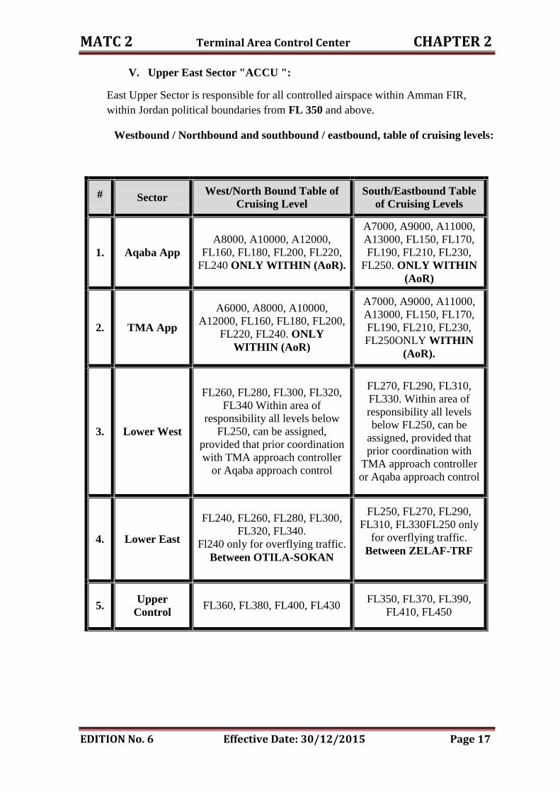
V. Upper East Sector "ACCU ":
East Upper Sector is responsible for all controlled airspace within Amman FIR,
within Jordan political boundaries from FL 350 and above.
Westbound / Northbound and southbound / eastbound, table of cruising levels:
# Sector West/North Bound Table of
Cruising Level
South/Eastbound Table
of Cruising Levels
1. Aqaba App
A8000, A10000, A12000,
FL160, FL180, FL200, FL220,
FL240 ONLY WITHIN (AoR).
A7000, A9000, A11000,
A13000, FL150, FL170,
FL190, FL210, FL230,
FL250. ONLY WITHIN
(AoR)
2. TMA App
A6000, A8000, A10000,
A12000, FL160, FL180, FL200,
FL220, FL240. ONLY
WITHIN (AoR)
A7000, A9000, A11000,
A13000, FL150, FL170,
FL190, FL210, FL230,
FL250ONLY WITHIN
(AoR).
3. Lower West
FL260, FL280, FL300, FL320,
FL340 Within area of
responsibility all levels below
FL250, can be assigned,
provided that prior coordination
with TMA approach controller
or Aqaba approach control
FL270, FL290, FL310,
FL330. Within area of
responsibility all levels
below FL250, can be
assigned, provided that
prior coordination with
TMA approach controller
or Aqaba approach control
4. Lower East
FL240, FL260, FL280, FL300,
FL320, FL340.
Fl240 only for overflying traffic.
Between OTILA-SOKAN
FL250, FL270, FL290,
FL310, FL330FL250 only
for overflying traffic.
Between ZELAF-TRF
5. Upper
Control FL360, FL380, FL400, FL430
FL350, FL370, FL390,
FL410, FL450

MATC 2 Terminal Area Control Center CHAPTER 2
EDITION No. 6 Effective Date: 30/12/2015 Page 18
VI. TACC Supervisor:
Operational Supervisor position with the capability of the following special
functions:
1. CMD.
2. DBM.
3. Main SDD with special features and FDD.
4. Two printers.
5. Two separate telephones.
6. Door monitor camera.
2.3.3. Sector Manning Level:
It is the responsibility of the TACC Supervisor or Watch Supervisor to ensure that sectors
are manned to meet traffic demand. The following manning levels are given for guidance
but the minimum manning levels shall not be reduced.
Controllers allocated to a control position or workstation will carry out a full handover
with the controller they are taking over from and remaining at their position until relieved.
NOTE: The hand over shall be not less than 10 minutes.
It is required that supervisors publish a list of controllers work positions and relief breaks
for each duty shift.
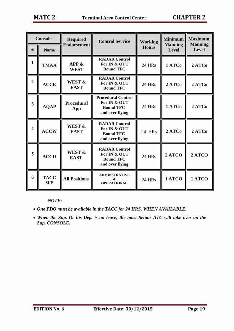
MATC 2 Terminal Area Control Center CHAPTER 2
EDITION No. 6 Effective Date: 30/12/2015 Page 19
Console
Required
Endorsement Control Service
Working
Hours
Minimum
Manning
Level
Maximum
Manning
Level # Name
1
TMAA APP &
WEST
RADAR Control For IN & OUT
Bound TFC
24 HRs
1 ATCo 2 ATCo
2
ACCE
WEST &
EAST
RADAR Control For IN & OUT
Bound TFC 24 HRs 2 ATCo 2 ATCo
3
AQAP
Procedural
App
Procedural Control For IN & OUT
Bound TFC and over flying
24 HRs 1 ATCo 2 ATCo
4
ACCW
WEST &
EAST
RADAR Control For IN & OUT
Bound TFC and over flying
24 HRs 2 ATCo 2 ATCo
5
ACCU
WEST &
EAST
RADAR Control For IN & OUT
Bound TFC
and over flying
24 HRs
2 ATCO
2 ATCO
6
TACC
SUP
All Positions
ADMINSTRATIVE &
OPERATIONAL 24 HRs
1 ATCO
1 ATCO
NOTE:
One FDO must be available in the TACC for 24 HRS, WHEN AVAILABLE.
When the Sup. Or his Dep. is on leave; the most Senior ATC will take over on the
Sup. CONSOLE.
MATC 2 Terminal Area Control Center CHAPTER 2
EDITION No. 6 Effective Date: 30/12/2015 Page 20
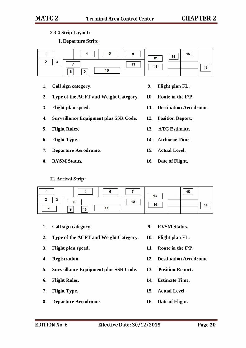
2.3.4 Strip Layout:
I. Departure Strip:
1. Call sign category. 9. Flight plan FL.
2. Type of the ACFT and Weight Category. 10. Route in the F/P.
3. Flight plan speed. 11. Destination Aerodrome.
4. Surveillance Equipment plus SSR Code. 12. Position Report.
5. Flight Rules. 13. ATC Estimate.
6. Flight Type. 14. Airborne Time.
7. Departure Aerodrome. 15. Actual Level.
8. RVSM Status. 16. Date of Flight.
II. Arrival Strip:
1. Call sign category. 9. RVSM Status.
2. Type of the ACFT and Weight Category. 10. Flight plan FL.
3. Flight plan speed. 11. Route in the F/P.
4. Registration. 12. Destination Aerodrome.
5. Surveillance Equipment plus SSR Code. 13. Position Report.
6. Flight Rules. 14. Estimate Time.
7. Flight Type. 15. Actual Level.
8. Departure Aerodrome. 16. Date of Flight.
MATC 2 Terminal Area Control Center CHAPTER 2
EDITION No. 6 Effective Date: 30/12/2015 Page 21
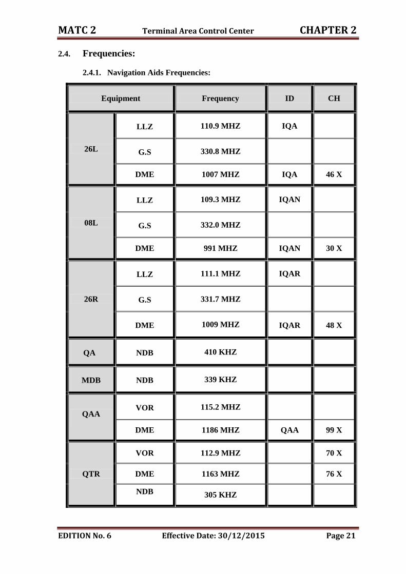
2.4. Frequencies:
2.4.1. Navigation Aids Frequencies:
Equipment Frequency ID CH
26L
LLZ 110.9 MHZ IQA
G.S 330.8 MHZ
DME 1007 MHZ IQA 46 X
08L
LLZ 109.3 MHZ IQAN
G.S 332.0 MHZ
DME 991 MHZ IQAN 30 X
26R
LLZ 111.1 MHZ IQAR
G.S 331.7 MHZ
DME 1009 MHZ IQAR 48 X
QA NDB 410 KHZ
MDB NDB 339 KHZ
QAA VOR 115.2 MHZ
DME 1186 MHZ QAA 99 X
QTR
VOR 112.9 MHZ 70 X
DME 1163 MHZ 76 X
NDB 305 KHZ
MATC 2 Terminal Area Control Center CHAPTER 2
EDITION No. 6 Effective Date:30/12/2015 Page 22
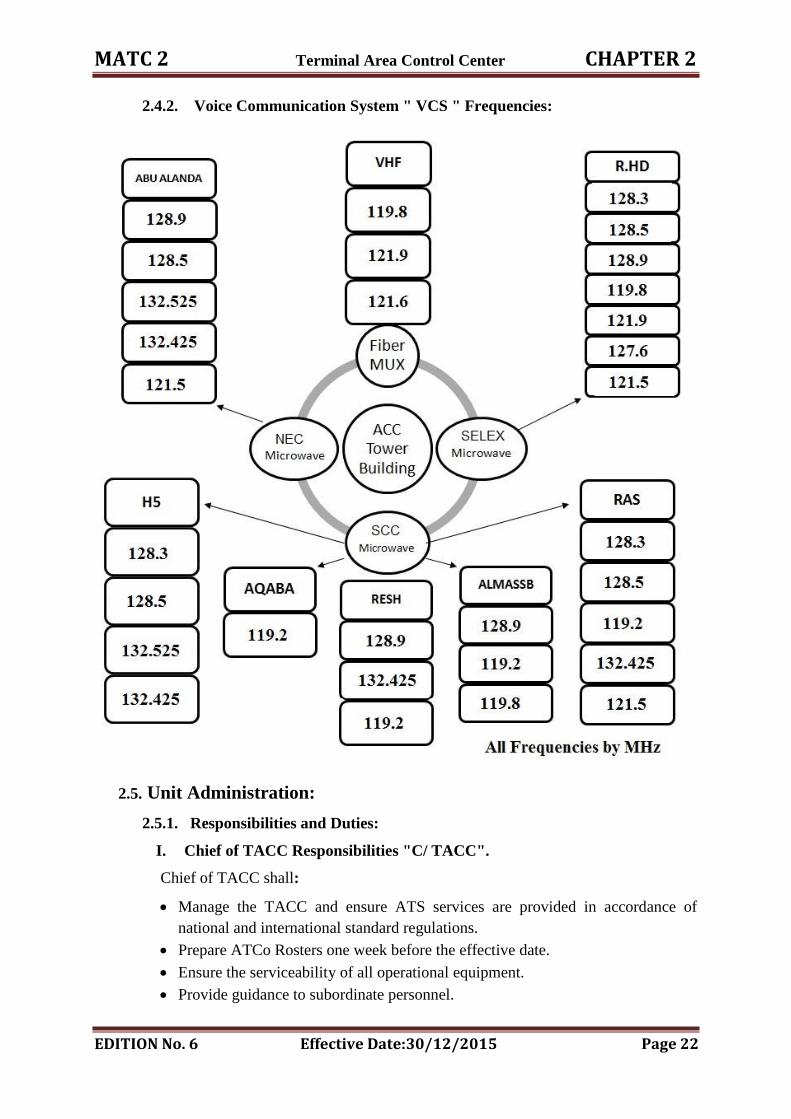
2.4.2. Voice Communication System " VCS " Frequencies:
2.5. Unit Administration:
2.5.1. Responsibilities and Duties:
I. Chief of TACC Responsibilities "C/ TACC".
Chief of TACC shall:
Manage the TACC and ensure ATS services are provided in accordance of
national and international standard regulations.
Prepare ATCo Rosters one week before the effective date.
Ensure the serviceability of all operational equipment.
Provide guidance to subordinate personnel.
MATC 2 Terminal Area Control Center CHAPTER 2
EDITION No. 6 Effective Date:30/12/2015 Page 23
Evaluate personnel performance.
Ensure that the NOTAM file is kept up-to-date.
Ensure that ASRs are filed on all violations, incidents etc.
Follow up absence or sick leaves.
Maintain Unit Endorsements and medical certificates.
Submit to DANS a monthly report covering all aspects of TACC operations.
Ensure that all annual leaves or any leave are signed by the watch supervisor and
to report it for DANS.
II. TACC Shift Supervisor Responsibilities:
TACC Supervisor is responsible to the Chief of TACC for the safe and efficient
operation of the ATC facility by the duty controllers.
III. TACC Shift Supervisor Duties:
TACC Shift Supervisor shall:
Supervise ATC staff and ensure that ATC services are provided in accordance of
MATC 1 and MATC 2.
Manage ATC staff to meet the traffic demand.
Ensure that all operational equipment & NAV. Aids are serviceable or under
maintenance and the status is recorded in the ATC Logbook and brought to the
attention of controllers.
Ensure that all his or her shift members holding a valid ATC License and valid
medical certificate.
Provide guidance to subordinate personnel.
Evaluate personnel performance and make recommendations concerning their
suitability, efficiency and potential.
Maintain discipline during the watch.
Not to give any information about unusual situation within AMMAN FIR.
Ensure ASRs are filed on all violations incidents, etc. during the period of watch.
Control all emergency or VIP flights.
Record absence or sick leave in the ATC Logbook in the absence of TACC SUP.
Coordinate and implement flow control.
Ensure that all staff is briefed and a full and complete handover is carried out
between watches.
NOTE: The hand over shall be not less than 10 minutes.
Sign all the annual and official leaves of ATC staff in his shift.
Select Sectorization.
Select area of alerts.
Coordinate over flight and /or landing permissions for the following cases:
a) Emergency.
b) Humanitarian.
MATC 2 Terminal Area Control Center CHAPTER 2
EDITION No. 6 Effective Date:30/12/2015 Page 24
c) Technical.
d) Re - fuelling.
IV. Deputy Shift Supervisor Duties:
Deputy Supervisor shall perform the same responsibilities and duties of the TACC
supervisor.
V. Supervisor of OJT Duties:
OJT supervisor is responsible to the chief of unit for the training of the staff at QAIA
TACC, OJT supervisor shall:
Supervise all OJT for all positions in the TACC.
Record all training hours for all OJT at the TACC.
Submit to chief of TACC monthly report covering all aspects of OJT operations,
coaches, and trainees.
Prepare all annual checks and, or, refresher courses.
Take part of assessment for ATC ratings, rating validity and examinations.
Maintain unit rating and endorsements.
VI. RADAR Controller Duties:
RADAR controller is responsible for the executive control of aircraft within the sector.
The RADAR controller responsibilities include:
Identifying and tracking aircraft under his control.
Applying non-RADAR separation when RADAR is not efficient or failed.
Maintaining an up-to-date flight progress display.
Accepting and transferring aircraft to other sectors.
Where coordination is required, ensuring that coordination has been carried out
before aircraft is transferred.
Other duties, which may be assigned by the TACC Shift SUP.
VII. Planner Controller Duties:
The main task is to assist the RADAR controller to the maximum extent possible.
The planner controller is responsible for the receipt and dissemination of all data relating to
aircraft movements within the sector. The planner controller duties include:
Receiving and processing estimates and revisions and manual preparation of
FPLSs in the event of any degradation in the system or failure.
Monitoring the frequency and assisting the RADAR controller in maintaining an
up-to-date flight progress display.
Passing estimates, revisions and EATs to the relevant sectors.
MATC 2 Terminal Area Control Center CHAPTER 2
EDITION No. 6 Effective Date:30/12/2015 Page 25
Alerting the RADAR controller of any apparent conflict evident from the traffic
display, which requires solution.
Coordination with the relevant Sectors.
In the event of full RADAR failure, assist the RADAR controller in re-
establishing procedural separation.
Other duties that may be assigned by the TACC Shift SUP.
VIII. Flight Data Operator Duties " FDO ":
Receive and print estimates from adjacent.
Create, modify and amend flight plan items.
Insert the registration mark in Plan Window for each flight plan when so
available.
He is fully responsible for the AFTN receptions.
Validate the ATIS messages.
Amend and update the meteorological information using area forecast reception
bulletins.
Archive the over flying permissions, when needed.
Archive FPSs at the end of the day (2359) UTC and set aside the TRF , OTILA
and METSA positions strips for en-route changes calculations.
2.5.2 Taking Over Watch:
On taking over watch, controllers shall carry out the following actions:
1. Check the current weather at OJAI, OJAM and OJAQ.
2. Check the Amman Area forecast weather for the period of watch.
3. Check the serviceability and maintenance periods of facilities and Nav. Aids
relevant to Approach Control.
4. Check NOTAMs in force.
5. Check any revisions to procedures.
6. Check the details of any special operations planned during the period of watch.
7. Check the runways in use at OJAI and OJAM and the terminal flow direction.
8. Check the accuracy and completeness of the prepared flight plan data and flight
progress board.
9. Check the traffic situation.
10. Check the serviceability of the ATC equipment and report all deficiencies to
the Chief of TACC.
11. Sign the watch log sheet for the sector.
2.5.3 Leave:
1. All leave applications must be submitted to the Watch Supervisor for approval.
2. TACC Shift Supervisor should not approve more than one leave request from
the same watch on the same day unless there are special circumstances.
MATC 2 Terminal Area Control Center CHAPTER 2
EDITION No. 6 Effective Date:30/12/2015 Page 26
2.5.4 Control Room Discipline:
1. The TACC Shift Supervisor will compile a duty roster at the commencement of
the shift and this will be displayed on the Operations Room notice board.
2. The duty roster will show the sector manning requirements and hours and will
only be varied on the authority of the TACC Shift Supervisor.
3. Smoking, Eating of Food or Drinking are prohibited in the Operation Room.
4. ATCo shall not leave his/her allocated control position until relieved by
another ATCo or unless the control position is closed down on the instructions
of the Chief of TACC.
5. All staff not allocated to control positions on the Duty Roster will leave the
Operations Room.
6. Any visits to the Operations Room must be approved by the TACC chief.
7. No private telephone calls will be made or accepted in the Operations Room.
8. It is the responsibility of controllers to reach the TACC by any means in the
event that they miss the TACC official transport.
9. On arrival at the TACC, controllers must proceed direct to the control room;
notify their arrival to the TACC Shift Supervisor and be assigned their duty.
2.5.5 Radio / Telephone Discipline:
Good R/T Discipline will be observed at all times.
REMEMBER YOU ARE REPRESENTING JORDAN.
Use Standard Phraseology at all times.
DO NOT ARGUE.
DO NOT BE AGGRESSIVE.
Accept any criticism or abuse with Standard Phraseology.
"ROGER YOUR MESSAGE IS COPIED"
Report any incidents or problems to the TACC Chief.
2.5.6 Read-Back of clearances & Implementation:
Read back requirements have been introduced in the interests of flight safety. The
noncompliance of the read back requirement is directly related to the possible seriousness
of a misunderstanding in the transmission and reception of ATC clearances and
instructions. Strict adherence to read back procedures ensures, not only that the clearance
has been received correctly but also that the clearance was transmitted as intended. It also
serves as a check that the right aircraft, and only that aircraft, will take the proper action
on the clearance.
Purpose:
1. To develop read back procedures and Implementation process.
MATC 2 Terminal Area Control Center CHAPTER 2
EDITION No. 6 Effective Date:30/12/2015 Page 27
2. To ensure the effective mechanism for the implementation of read back
procedure.
Read back of ATC clearances:
a) Flight crew responsibility:
1. The flight crew shall read back to the air traffic controller safety-related parts of
ATC clearances and instructions which are transmitted by voice.
2. Pilot should briefly read back the contents of the following items, included in
ATC clearances, instructions or approvals, transmitted through voice
communication by ATC facility, Mobile Communication Service facility or
International Air-ground Communication Service facility unless ATC facility
instructs not to reply:
Clearances or instructions to take-off, land on, cross, taxi on, line up and hold
short of any runway.
Clearances or instructions regarding a route of flight including (SID,
Transition and STAR).
Clearances or instructions regarding altitude, altitude restrictions, heading and
speed.
Holding instruction, approach clearance or go-around instruction.
Radio frequency instruction.
Conditional clearances or instructions.
3. The use of the term “ROGER” or “WILCO “is not an acceptable read back as it
does not allow the controller to confirm or correct the clearance or instruction.
4. The read back message shall always include the flight call sign ( flight number \
call sign).
5. A pilot shall not switch immediately to the next sector frequency following read
back of controller‟s instruction.
6. A pilot should ensure confirmation of read-back is received:
Clearances or instructions, including conditional clearances, shall be read back
or acknowledged in a manner to clearly indicate that they have been understood
and will be complied with.
SSR codes and Runway in use (except when transmitted simultaneously to all
aircraft hearing the same frequency.)
Controller responsibility:
1. The controller shall listen to the read-back to ascertain that the clearance or
instruction has been correctly acknowledged by the flight crew.
MATC 2 Terminal Area Control Center CHAPTER 2
EDITION No. 6 Effective Date:30/12/2015 Page 28
2. The controller shall listen to the read-back to as certain that the clearance or
instruction has been correctly acknowledged by the flight crew and shall to take
immediate action to correct any descriptions reverted by the read-back..
3. The Controller should pass a clearance slowly and clearly since the pilot needs to
write it down and wasteful repetition will thus be avoided. In any case controllers
should avoid passing a clearance to a pilot engaged in complicated taxiing
maneuvers and on no occasion should a clearance be passed when the pilot is
engaged in line up or take-off maneuvers.
4. The word "take-off" are used only when an aircraft is cleared for take-off, or when
cancelling a take- off clearance. At other times the word "departure" or "airborne"
is used.
5. If an aircraft read back of a clearance or instruction is incorrect, the controller shall
transmit the word "NEGATIVE" followed by the correct version.
6. If there is a doubt as to whether a pilot can comply with an ATC clearance or
instruction or not, the controller may follow the clearance or instruction by the
phrase "if not possible advice", and subsequently offer an alternative.
Air Traffic Management Responsibility:
1. The ATM establishes appropriate supervisory means to ensure the correct
application of standard phraseology procedures by ATCO‟s.
2. The ATM implements the recommendation by the International Civil Aviation
Organization (ICAO) in Annex 11 Air Traffic Services, paragraph 3.3.3. stating
that: „air traffic control units should be equipped with devices that record
background communication and the aural environment at air traffic controller
work stations, capable of retaining the information recorded during at least the last
twenty-four hours of operation.‟
3. The ATM should conduct all communications associated with the operation of the
runway on the same frequency as utilized for the take-off and landing of aircraft
and all communications associated with the operation of the taxiways should be
conducted on a different designated frequency.
4. The ATM should ensure that all communications associated with the operation of
the runway and the taxiways are conducted in standard aviation English and in
accordance with ICAO language requirements for air-ground radiotelephony
communications.
5. The ATM should amend work procedures for the access to the maneuvering area
during LVP.
6. The ATM should ensure an effective safety assessment of tasks which may affect
the safety of air traffic control operations.
MATC 2 Terminal Area Control Center CHAPTER 2
EDITION No. 6 Effective Date:30/12/2015 Page 29
7. The ATM should review the MATC I & II to ensure that common practices and
local instructions are contained in MATC I & II and that they are not in
contradiction.
8. The ATM should establish written instructions in the MATC I & II and supervise
their operational implementation to ensure the clear and unambiguous.
9. The ATM should implement back-up communication means.
Air Traffic Control mechanism for implementation of read-back clearance:
1. Randomly check to the recorded audio tapes, for all air traffic control units at least
one time monthly.
2. Supervision by the Chiefs of Units to review the Read back.
3. Issuance of corrective action (instructions).
4. Develop of a training program for refined violations of the Procedures.
5. Send and distribute a Read back form for the reviewed tapes for all concerned
units.
CHAPTER THREE
DEEMED SEPARATION
MATC 2 Deemed Separation CHAPTER 3
EDITION No. 6 Effective Date:30/12/2015 Page 30
3. DEEMED SEPARATION
3.1 TMA Deemed Separation:
To be determined when all procedures are completed, in the meanwhile standard
procedures " MATC 1 - chapter 5 " for separation in non-RADAR environment
shall be applicable.
3.2 En-route Deemed Separation:
The following deemed separation minima may apply in Amman FIR concerning
TFC using RNAV 5.
3.2.1 ATS Route A 412:
Separation:
1. Northbound TFC on ATS route L513 is deemed to be separated from A412
when passing BUSRA point.
2. Northbound TFC on ATS route M449 is deemed to be separated from A412
before passing EGLOT or after passing BUSRA.
3. Northbound TFC on G662 is deemed to be separated from A412, at or before
passing DESLI and after passing BUSRA.
4. Northbound TFC on ATS route UM690 is deemed to be separated from A412
at or before passing DESLI.
5. Eastbound TFC on L200 is deemed to be separated from A412 and UR785,
after passing KUMLO.
6. Southbound TFC on ATS route M449 is deemed to be separated from A412
when passing ELNOR.
7. Southbound TFC on ATS route G662 is deemed to be separated from A412
after passing DESLI.
8. Southbound TFC on ATS Route UM690 is deemed to be separated from A412
before passing DESLI.
9. Westbound TFC on ATS route L200 is deemed to be separated from A412
before passing DAPUK.
NOTE: INS may be used instead, where DME reading is not available.
10. Westbound TFC on ATS route A412 is deemed to be separated from:
a) UR785, UL 768 when passing DAXEN.
b) UM690, when passing NADEK.
MATC 2 Deemed Separation CHAPTER 3
EDITION No. 6 Effective Date:30/12/2015 Page 31
c) G662, before passing NADEK or after passing LUDAN.
d) L513 and M449 before passing NADEK.
e) RECIPROCAL tracks not through DAXEN and LUDAN accordingly.
f) TFC holding over QAA/DVOR at high level holding, at or before
ASLON.
11. Eastbound TFC on A412 is deemed to be separated from:
a) L513, M449 and G662 when passing NADEK.
b) UM690, before passing KUPRI.
c) UR785 and UL 768, at or before passing DAXEN.
d) Reciprocal tracks not through LUDAN and DAXEN accordingly.
e) TFC holding over QAA/DVOR at high level holding, at or later
ASLON.
3.2.2 ATS Route M 449:
This route extends from BUSRA point till the Saudi border at the point GIBET
having the following description:
1. Bi-directional route.
2. PBN performance " RNAV 5 " route specification.
3. Extends through the following points:
BUSRA – GIBOX – MESLO – GETUP – ALNOR – EGLOT – MAZAR
– HIDAN – PETRA - GIBET.
4. Full length 176 NM.
5. Table of cruising levels as following:
Eastbound TFC Westbound TFC
FL 290 , FL310 , FL330
FL 260 , FL 280 , FL 300,
FL 320 , FL 340 , FL 360,
FL 380 , FL 400 , FL 430
Separation:
1. Southbound TFC shall cross the waypoint MAZAR FL 250 or above, arrival
TFC to QAIA and MARKA airports shall cross MAZAR waypoint FL 260.
2. Southbound TFC shall be maintaining their optimum levels at or before
waypoint MAZAR "10 minutes prior to the CCBs with Jeddah & Riyadh
ACCs" clear of TFC within Jeddah and Riyadh FIR "south of GIBET and east
of DEESA".
MATC 2 Deemed Separation CHAPTER 3
EDITION No. 6 Effective Date:30/12/2015 Page 32
3. No level change after passing HIDAN waypoint. Or as coordinated with Jeddah
or Riyadh ACCs.
4. Contact point for southbound TFC is PETRA to the accepting unit of control
"Jeddah or Riyadh ACCs".
5. GIBET waypoint is considered to be the release waypoint of control by the
transferring unit "AMMAN TACC" to the accepting unit "Jeddah &Riyadh
ACCs" for southbound TFC.
6. Successive southbound TFC will be separated as follows:
a) 10 minutes same level and speed constant or ahead A/C is faster.
b) 5 minutes at the CCB, provided the leading aircraft is 20 KTS faster.
c) 20 NM based on the use of surveillance system provided that both A/C are
constant speed or the leading aircraft is faster.
NOTE: RADAR separation will be implemented according to the LOA,
Annex E/E1 "RADAR separation minima".
7. Southbound TFC on M449 passing MAZAR waypoint is clear of TFC on
R652.
8. Southbound TFC on M449 before passing HIDAN waypoint is clear of TFC:
a) When eastbound TFC on UB411 is passing PETRA waypoint.
b) When westbound TFC on UB411 is passing PETRA waypoint.
9. Northbound TFC on M449 south of GIBET waypoint is clear of southbound
TFC north of MAZAR waypoint.
10. Northbound TFC via GIBET and westbound TFC via DEESA waypoints shall
be vertically separated by Jeddah or Riyadh ACCs.
11. Northbound TFC ,north of PETRA waypoint is deemed to be separated from
TFC:
a) On UB411 West of TAMIM waypoint
b) East of DEESA waypoint provided that northbound TFC passing HIDAN.
c) South of GIBET waypoint, Provided that both A/C are under AMMAN
control.
d) On R652, while the northbound TFC on M449 is still south of HIDAN
waypoint.
12. Northbound TFC at or before ALNOR waypoint is clear of G662.
13. Northbound TFC at or before EGLOT waypoint is deemed to be separated of
N 318.
14. Southbound TFC is clear of G662 when passing ALNOR waypoint.
15. Southbound TFC is deemed to be separated of N 318, when passing EGLOT
waypoint.
MATC 2 Deemed Separation CHAPTER 3
EDITION No. 6 Effective Date:30/12/2015 Page 33
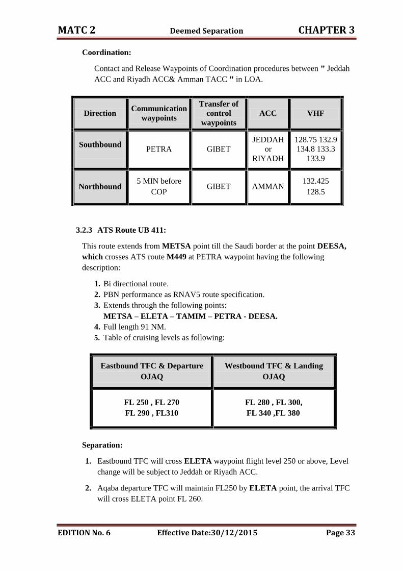
Coordination:
Contact and Release Waypoints of Coordination procedures between " Jeddah
ACC and Riyadh ACC& Amman TACC " in LOA.
Direction Communication
waypoints
Transfer of
control
waypoints
ACC VHF
Southbound
PETRA GIBET
JEDDAH
or
RIYADH
128.75 132.9
134.8 133.3
133.9
Northbound
5 MIN before
COP
GIBET AMMAN 132.425
128.5
3.2.3 ATS Route UB 411:
This route extends from METSA point till the Saudi border at the point DEESA,
which crosses ATS route M449 at PETRA waypoint having the following
description:
1. Bi directional route.
2. PBN performance as RNAV5 route specification.
3. Extends through the following points:
METSA – ELETA – TAMIM – PETRA - DEESA.
4. Full length 91 NM.
5. Table of cruising levels as following:
Eastbound TFC & Departure
OJAQ
Westbound TFC & Landing
OJAQ
FL 250 , FL 270
FL 290 , FL310
FL 280 , FL 300,
FL 340 ,FL 380
Separation:
1. Eastbound TFC will cross ELETA waypoint flight level 250 or above, Level
change will be subject to Jeddah or Riyadh ACC.
2. Aqaba departure TFC will maintain FL250 by ELETA point, the arrival TFC
will cross ELETA point FL 260.
MATC 2 Deemed Separation CHAPTER 3
EDITION No. 6 Effective Date:30/12/2015 Page 34
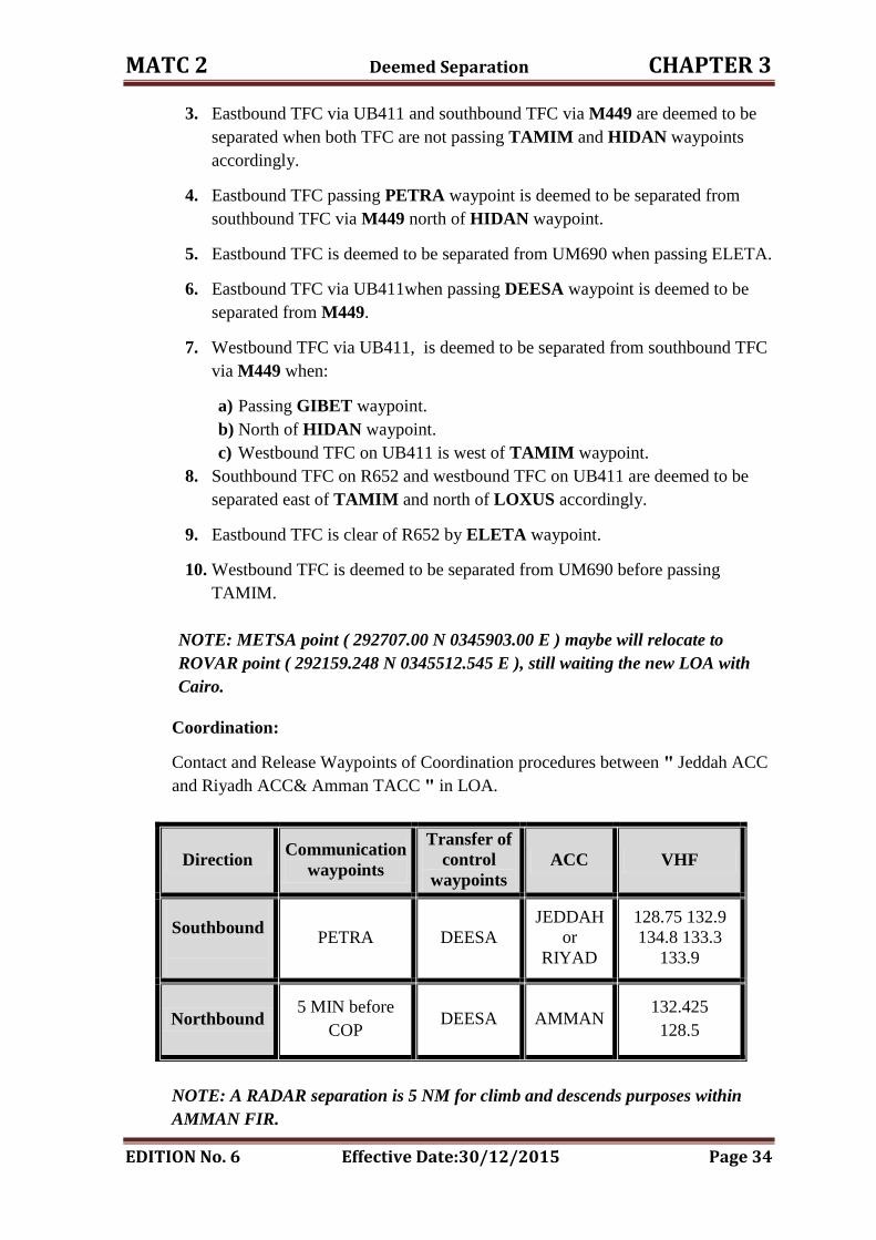
3. Eastbound TFC via UB411 and southbound TFC via M449 are deemed to be
separated when both TFC are not passing TAMIM and HIDAN waypoints
accordingly.
4. Eastbound TFC passing PETRA waypoint is deemed to be separated from
southbound TFC via M449 north of HIDAN waypoint.
5. Eastbound TFC is deemed to be separated from UM690 when passing ELETA.
6. Eastbound TFC via UB411when passing DEESA waypoint is deemed to be
separated from M449.
7. Westbound TFC via UB411, is deemed to be separated from southbound TFC
via M449 when:
a) Passing GIBET waypoint.
b) North of HIDAN waypoint.
c) Westbound TFC on UB411 is west of TAMIM waypoint.
8. Southbound TFC on R652 and westbound TFC on UB411 are deemed to be
separated east of TAMIM and north of LOXUS accordingly.
9. Eastbound TFC is clear of R652 by ELETA waypoint.
10. Westbound TFC is deemed to be separated from UM690 before passing
TAMIM.
NOTE: METSA point ( 292707.00 N 0345903.00 E ) maybe will relocate to
ROVAR point ( 292159.248 N 0345512.545 E ), still waiting the new LOA with
Cairo.
Coordination:
Contact and Release Waypoints of Coordination procedures between " Jeddah ACC
and Riyadh ACC& Amman TACC " in LOA.
Direction Communication
waypoints
Transfer of
control
waypoints
ACC VHF
Southbound
PETRA DEESA
JEDDAH
or
RIYAD
128.75 132.9
134.8 133.3
133.9
Northbound
5 MIN before
COP
DEESA AMMAN 132.425
128.5
NOTE: A RADAR separation is 5 NM for climb and descends purposes within
AMMAN FIR.
MATC 2 Deemed Separation CHAPTER 3
EDITION No. 6 Effective Date:30/12/2015 Page 35
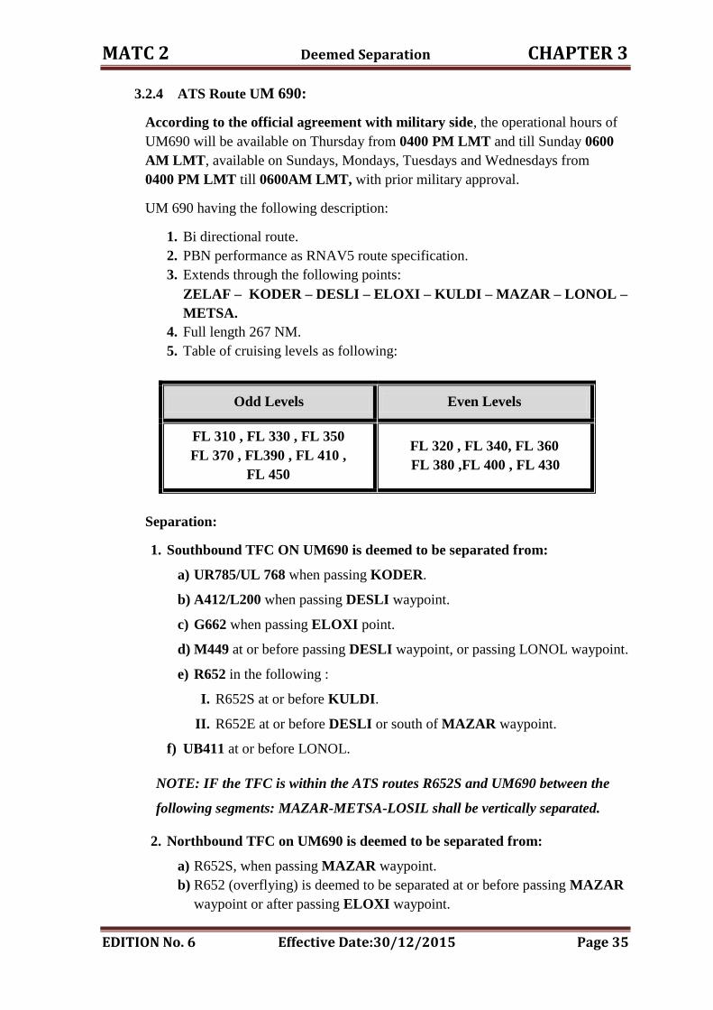
3.2.4 ATS Route UM 690:
According to the official agreement with military side, the operational hours of
UM690 will be available on Thursday from 0400 PM LMT and till Sunday 0600
AM LMT, available on Sundays, Mondays, Tuesdays and Wednesdays from
0400 PM LMT till 0600AM LMT, with prior military approval.
UM 690 having the following description:
1. Bi directional route.
2. PBN performance as RNAV5 route specification.
3. Extends through the following points:
ZELAF – KODER – DESLI – ELOXI – KULDI – MAZAR – LONOL –
METSA.
4. Full length 267 NM.
5. Table of cruising levels as following:
Odd Levels Even Levels
FL 310 , FL 330 , FL 350
FL 370 , FL390 , FL 410 ,
FL 450
FL 320 , FL 340, FL 360
FL 380 ,FL 400 , FL 430
Separation:
1. Southbound TFC ON UM690 is deemed to be separated from:
a) UR785/UL 768 when passing KODER.
b) A412/L200 when passing DESLI waypoint.
c) G662 when passing ELOXI point.
d) M449 at or before passing DESLI waypoint, or passing LONOL waypoint.
e) R652 in the following :
I. R652S at or before KULDI.
II. R652E at or before DESLI or south of MAZAR waypoint.
f) UB411 at or before LONOL.
NOTE: IF the TFC is within the ATS routes R652S and UM690 between the
following segments: MAZAR-METSA-LOSIL shall be vertically separated.
2. Northbound TFC on UM690 is deemed to be separated from:
a) R652S, when passing MAZAR waypoint.
b) R652 (overflying) is deemed to be separated at or before passing MAZAR
waypoint or after passing ELOXI waypoint.
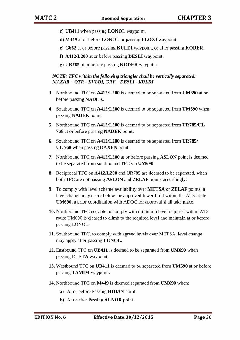
MATC 2 Deemed Separation CHAPTER 3
EDITION No. 6 Effective Date:30/12/2015 Page 36
c) UB411 when passing LONOL waypoint.
d) M449 at or before LONOL or passing ELOXI waypoint.
e) G662 at or before passing KULDI waypoint, or after passing KODER.
f) A412/L200 at or before passing DESLI waypoint.
g) UR785 at or before passing KODER waypoint.
NOTE: TFC within the following triangles shall be vertically separated:
MAZAR – QTR - KULDI, GRY – DESLI - KULDI.
3. Northbound TFC on A412/L200 is deemed to be separated from UM690 at or
before passing NADEK.
4. Southbound TFC on A412/L200 is deemed to be separated from UM690 when
passing NADEK point.
5. Northbound TFC on A412/L200 is deemed to be separated from UR785/UL
768 at or before passing NADEK point.
6. Southbound TFC on A412/L200 is deemed to be separated from UR785/
UL 768 when passing DAXEN point.
7. Northbound TFC on A412/L200 at or before passing ASLON point is deemed
to be separated from southbound TFC via UM690.
8. Reciprocal TFC on A412/L200 and UR785 are deemed to be separated, when
both TFC are not passing ASLON and ZELAF points accordingly.
9. To comply with level scheme availability over METSA or ZELAF points, a
level change may occur below the approved lower limit within the ATS route
UM690, a prior coordination with ADOC for approval shall take place.
10. Northbound TFC not able to comply with minimum level required within ATS
route UM690 is cleared to climb to the required level and maintain at or before
passing LONOL.
11. Southbound TFC, to comply with agreed levels over METSA, level change
may apply after passing LONOL.
12. Eastbound TFC on UB411 is deemed to be separated from UM690 when
passing ELETA waypoint.
13. Westbound TFC on UB411 is deemed to be separated from UM690 at or before
passing TAMIM waypoint.
14. Northbound TFC on M449 is deemed separated from UM690 when:
a) At or before Passing HIDAN point.
b) At or after Passing ALNOR point.
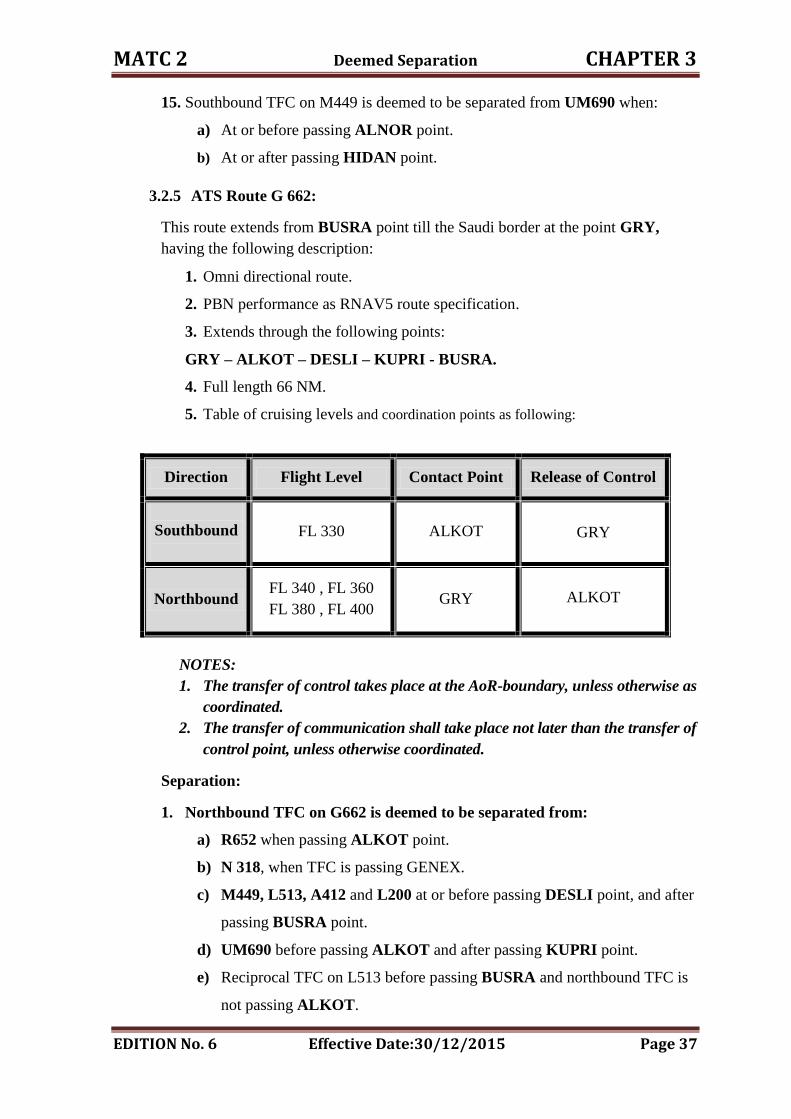
MATC 2 Deemed Separation CHAPTER 3
EDITION No. 6 Effective Date:30/12/2015 Page 37
15. Southbound TFC on M449 is deemed to be separated from UM690 when:
a) At or before passing ALNOR point.
b) At or after passing HIDAN point.
3.2.5 ATS Route G 662:
This route extends from BUSRA point till the Saudi border at the point GRY,
having the following description:
1. Omni directional route.
2. PBN performance as RNAV5 route specification.
3. Extends through the following points:
GRY – ALKOT – DESLI – KUPRI - BUSRA.
4. Full length 66 NM.
5. Table of cruising levels and coordination points as following:
Direction Flight Level Contact Point Release of Control
Southbound
FL 330 ALKOT GRY
Northbound
FL 340 , FL 360
FL 380 , FL 400
GRY ALKOT
NOTES:
1. The transfer of control takes place at the AoR-boundary, unless otherwise as
coordinated.
2. The transfer of communication shall take place not later than the transfer of
control point, unless otherwise coordinated.
Separation:
1. Northbound TFC on G662 is deemed to be separated from:
a) R652 when passing ALKOT point.
b) N 318, when TFC is passing GENEX.
c) M449, L513, A412 and L200 at or before passing DESLI point, and after
passing BUSRA point.
d) UM690 before passing ALKOT and after passing KUPRI point.
e) Reciprocal TFC on L513 before passing BUSRA and northbound TFC is
not passing ALKOT.

MATC 2 Deemed Separation CHAPTER 3
EDITION No. 6 Effective Date:30/12/2015 Page 38
2. Southbound TFC on G662 is deemed to be separated from:
a) R652 at or before passing KUPRI point.
b) A412, L513, L200 and M449 when passing DESLI point.
c) UM690 when passing ALKOT point.
d) Reciprocal TFC, northbound before passing GRY and southbound TFC is
not passing KUPRI.
NOTE: Southbound TFC will proceed via N 318 after passing GRY/VOR.
3. Westbound TFC on N 318 is deemed to be separated from G662 when passing
GENEX waypoint.
4. Westbound TFC on R652 is deemed to be separated from G662 when passing
KIPAS point.
5. Northbound TFC on UM690 is deemed to be separated from G662 before
passing KULDI or after passing KODER.
6. Eastbound TFC on R652 is deemed to be separated from G662 at or before
passing QTR/VOR.
7. Jeddah / Riyadh ACCs shall ensure the required minimum separation between
westbound TFC via UL768 / B544 and G662 which are destined to overfly
Damascus FIR.
8. Amman TACC will ensure the minimum separation between southbound TFC
via G662 and UR785 / B544 which are destined to overfly Jeddah FIR.
CHAPTER FOUR
RADAR CONTROL
MATC 2 RADAR Control CHAPTER 4
EDITION No. 6 Effective Date: 30/12/2015 Page 39
4. RADAR CONTROL
4.1. General:
RADAR controller shall be responsible for adjusting RADAR display and for
carrying out adequate checks on the accuracy; RADAR controller shall satisfy
himself that the information presented on RADAR display is adequate for the
functions to be performed.
RADAR controller shall report to TACC supervisor any fault in the equipment or
any circumstances which makes impractical to provide RADAR service.
4.2. RADAR Identification :
Where SSR is used for identification, aircraft may be identified by one or more of
the following procedures:
I. Recognition of the aircraft identification in a SSR label;
NOTE: The use of this procedure requires that the code/call sign correlation is
achieved successfully, taking into account the Note following b) below.
II. Recognition of an assigned discrete code, the setting of which has been
verified, in a RADAR label; and
III. Direct recognition of the aircraft identification of a Mode S-equipped aircraft
in a RADAR label;
NOTE: The aircraft identification feature available in Mode S transponders
provides the means to identify directly individual aircraft on situation displays
and thus offers the potential to eliminate ultimately the recourse to Mode A
discrete codes for individual identification. This elimination will only be achieved
in a progressive manner depending on the state of deployment of suitable ground
and airborne installations.
IV. By transfer RADAR identity , by one of the following methods:
Designation of the position indication by automated means, provided
that only one position indication is thereby indicated and there is no
possible doubt of correct identification;
Notification of the aircraft’s discrete SSR code or aircraft address;
NOTE: Aircraft address would be expressed in the form of the alphanumerical
code of six hexadecimal characters.
Notification that the aircraft is SSR Mode S-equipped with an aircraft
identification feature when SSR Mode S coverage is available;
Notification that the aircraft is ADS-B-equipped with an aircraft
identification feature when compatible ADS-B coverage is available;
MATC 2 RADAR Control CHAPTER 4
EDITION No. 6 Effective Date: 30/12/2015 Page 40
Direct designation "pointing with the finger" of the position indication,
if the two situation displays are adjacent, or if a common “conference”
type of situation display is used;
NOTE: Attention must be given to any errors which might occur due to parallax
effects.
Designation of the position indication by reference to, or in terms of
bearing and distance from, a geographical position or navigational
facility accurately indicated on both situation displays, together with the
track of the observed position indication if the route of the aircraft is not
known to both controllers;
NOTE: Caution must be exercised before transferring identification using this
method, particularly if other position indications are observed on similar
headings and in close proximity to the aircraft under control.
Inherent RADAR deficiencies, such as inaccuracies in bearing and distance of the
RADAR position indications displayed on individual situation displays and parallax
errors, may cause the indicated position of an aircraft in relation to the known point
to differ between the two situation displays. The appropriate ATS authority may,
therefore, prescribe additional conditions for the application of this method, e.g.:
i. A maximum distance from the common reference point used by the two
controllers; and
ii. A maximum distance between the position indication as observed by the
accepting controller and the one stated by the transferring controller.
Where applicable, issuance of an instruction to the aircraft by the
transferring controller to change SSR code and the observation
of the change by the accepting controller; or
Issuance of an instruction to the aircraft by the transferring
controller to squawk/transmit IDENT and observation of this
response by the accepting controller.
NOTE: Use of procedures g) and h) requires prior coordination between the
controllers, since the indications to be observed by the accepting controller are of
short duration.
V. Observation of compliance with an instruction to set a specific code.
VI. Observation of compliance with an instruction to squawk IDENT.
NOTES:
1. In automated RADAR systems, the "IDENT" feature may be presented in
different ways, e.g. as a flashing of all or part of the position indication and
associated label.
2. Garbling of transponder replies may produce "IDENT"-type of indication,
nearly simultaneous “IDENT” transmissions within the same area may give
rise to errors in identification.
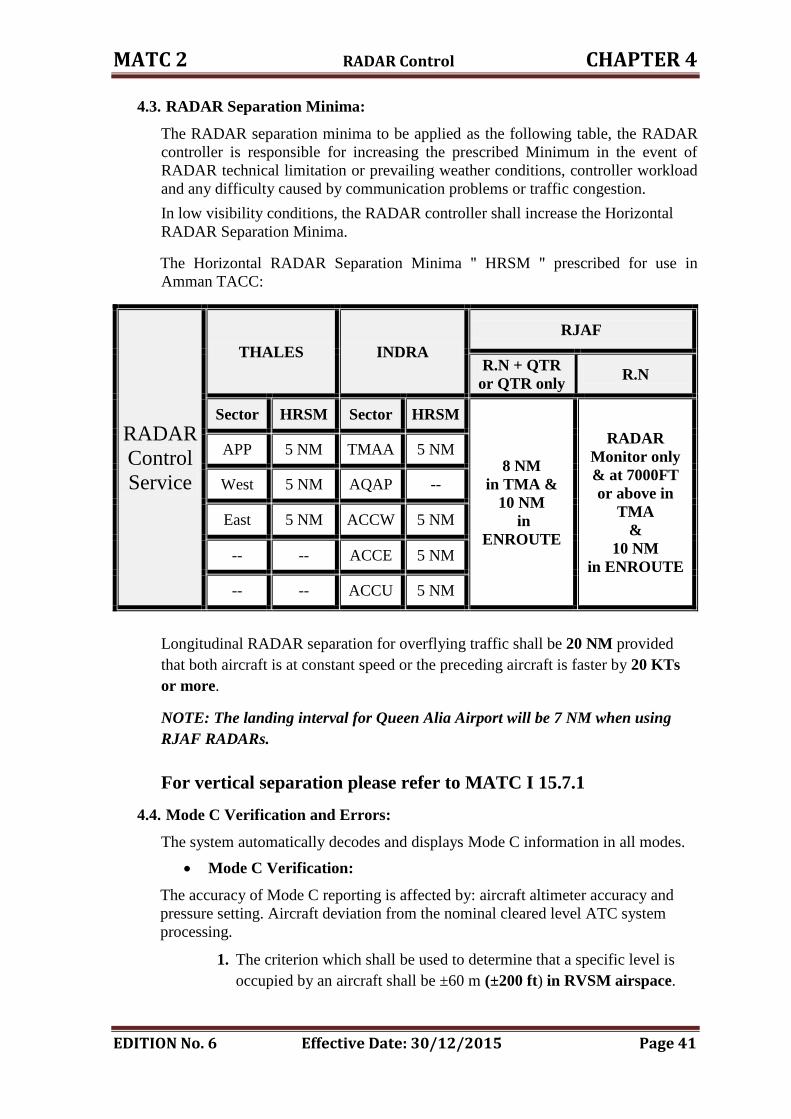
MATC 2 RADAR Control CHAPTER 4
EDITION No. 6 Effective Date: 30/12/2015 Page 41
4.3. RADAR Separation Minima:
The RADAR separation minima to be applied as the following table, the RADAR
controller is responsible for increasing the prescribed Minimum in the event of
RADAR technical limitation or prevailing weather conditions, controller workload
and any difficulty caused by communication problems or traffic congestion.
In low visibility conditions, the RADAR controller shall increase the Horizontal
RADAR Separation Minima.
The Horizontal RADAR Separation Minima " HRSM " prescribed for use in
Amman TACC:
RADAR
Control
Service
THALES INDRA
RJAF
R.N + QTR
or QTR only R.N
Sector HRSM Sector HRSM
8 NM
in TMA &
10 NM
in
ENROUTE
RADAR
Monitor only
& at 7000FT
or above in
TMA
&
10 NM
in ENROUTE
APP 5 NM TMAA 5 NM
West 5 NM AQAP --
East 5 NM ACCW 5 NM
-- -- ACCE 5 NM
-- -- ACCU 5 NM
Longitudinal RADAR separation for overflying traffic shall be 20 NM provided
that both aircraft is at constant speed or the preceding aircraft is faster by 20 KTs
or more.
NOTE: The landing interval for Queen Alia Airport will be 7 NM when using
RJAF RADARs.
For vertical separation please refer to MATC I 15.7.1
4.4. Mode C Verification and Errors:
The system automatically decodes and displays Mode C information in all modes.
Mode C Verification:
The accuracy of Mode C reporting is affected by: aircraft altimeter accuracy and
pressure setting. Aircraft deviation from the nominal cleared level ATC system
processing.
1. The criterion which shall be used to determine that a specific level is
occupied by an aircraft shall be ±60 m (±200 ft) in RVSM airspace.
MATC 2 RADAR Control CHAPTER 4
EDITION No. 6 Effective Date: 30/12/2015 Page 42
2. Aircraft Mode C indication is deemed to be acceptable if the pilot report
is within + / - 300 FT of the displayed level.
3. Once verified vacating is deemed to have occurred when the displayed
level +/- 300 FT and the climb or descend arrow indicates the correct
sense.
4. Passing is deemed to have occurred when the displayed level is more
than 300FT from the required level and the climb or descent arrow
indicates the correct sense.
5. Reaching a level is deemed to have occurred when the displayed level is
within 300FT from the required level and absence of climb or descent
arrow indicates level flight for three cycles i.e. + 12 Sec.
Mode C Errors:
1. If a mode C error is detected (after checking the aircraft pressure
setting). The aircraft will be instructed to stop Altimeter Squawk.
2. If Mode C and Mode 3/A are not independently, switched it will be
necessary to retain the Mode 3/A and accept the display of erroneous
Mode C which will be disregarded.
Phraseology:
ATC: CHECK ALTIMETER SETTING, CONFIRM the (level).
ATC: STOP SQUAWK CHARLIE WRONG INDICATION.
Reference: MATC 1, Chapter 12, point 12.4.3.12
4.5. SSR Codes:
4.5.1. General:
Jordan is part of the Middle East Region SSR code allocation plan. All states in the
region are allocated code blocks from the Mode A codes.
4.5.2. SSR Code Failure:
If known traffic is not identified due to aircraft SSR failure, Procedural separation
must be used, and coordination is required with the next control unit for acceptance.
4.5.3. Inbound SSR code assignment:
Inbound traffic to any Jordanian aerodrome will be code allocated by either:
1. Origination control unit or from the first country in the region and will be
accepted when receiving the estimate message.
2. Amman TACC will allocate a code to any inbound aircraft that does not
have an allocated code, or conflicts with any other assigned code, from the
block 0400 – 0477.
MATC 2 RADAR Control CHAPTER 4
EDITION No. 6 Effective Date: 30/12/2015 Page 43
4.5.4. Over fly SSR code assignment:
1. Amman TACC will accept this code as a part of the estimate message, and
use it for the flight in Amman FIR, and pass it with the estimate message to
the next FIR.
2. Amman TACC will allocate a code to any inbound aircraft that does not
have an allocated code, or conflicts with any other assigned code, from the
block 0700 – 0777.
4.5.5. Outbound SSR code assignment:
1. Amman TACC will allocate a code for outbound aircraft from the block
0700 – 0777.
2. All outbound traffic via Talaviv FIR, Talaviv ACC will pass the code to
Amman TACC.
4.5.6. Domestic SSR Codes:
1. Local flights will be allocated a code from the block 1101 – 1177.
2. Military flights will be allocated a code from the block 2400 – 2477.
NOTE: SSR code 2401 is reserved.
3. Aviation training academies flights will be allocated a code from the block
2200 – 2277.
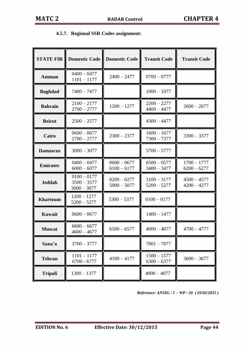
MATC 2 RADAR Control CHAPTER 4
EDITION No. 6 Effective Date: 30/12/2015 Page 44
4.5.7. Regional SSR Codes assignment:
STATE FIR Domestic Code Domestic Code Transit Code Transit Code
Amman 0400 – 0477
1101 – 1177 2400 – 2477 0700 – 0777
Baghdad 7400 – 7477 1000 – 1077
Bahrain 2100 – 2177
2700 – 2777 1200 – 1277
2200 – 2277
4400 – 4477 2600 – 2677
Beirut 2500 – 2577 4300 – 4477
Cairo 0600 – 0677
2700 – 2777 2300 – 2377
1600 – 1677
7300 – 7377 3300 – 3377
Damascus 3000 – 3077 5700 – 5777
Emirates 0400 – 0477
6000 – 6077
0600 – 0677
6100 – 6177
0500 – 0577
3400 – 3477
1700 – 1777
6200 – 6277
Jeddah
0100 – 0177
3500 – 3577
3000 – 3077
0200 – 0277
5000 – 5077
3100 – 3177
5200 – 5277
4500 – 4577
4200 – 4277
Khartoum 1200 – 1277
5200 – 5277 5300 – 5377 0100 – 0177
Kuwait 0600 – 0677 1400 – 1477
Muscat 6600 – 6677
4600 – 4677 6500 – 6577 4000 – 4077 4700 – 4777
Sana’a 3700 – 3777 7001 – 7077
Tehran 1101 – 1177
6700 - 6777 4100 – 4177
1500 – 1577
6300 – 6377 3600 – 3677
Tripoli 1300 – 1377 4000 – 4077
Reference: ANSIG / 1 – WP / 20 ( 03/02/2015 )
CHAPTER FIVE
TMA and AREA PROCEDURES

MATC 2 TMA & Area Procedure CHAPTER 5
EDITION No. 6 Effective Date: 30/12/2015 Page 45
5. TMA and AREA PROCEDURE
5.1. General:
The Amman TMA inbound and outbound traffic will be cleared on the system of
SID's and STAR's.
Traffic will only be cleared on non standard routes in the following circumstances:
Emergency.
Medical Flights.
Military Operations.
If RADAR Service is provided.
Classification of Jordan Airspace:
1. Class A: Class A comprises all controlled airspace within Amman FIR
above FL150.
2. Class C: Class C comprises all controlled airspace within Amman FIR
at FL 150 or below.
3. Class G: Class G comprises the rest of Amman FIR.
5.2. Outbound Traffic:
Departures are the responsibility of Approach Control Unit and all
departures will be released subject to Approach.
Outbound Release and Handover:
a) Outbound Silent Radar Handover:
1. It is clear of traffic holding in the TMA.
2. It is climbing to the standard outbound or agreed level.
3. RADAR is fully serviceable with Mode C functioning.
4. It is not subject to any restriction of speed or heading " own
navigation".
5. "10 NM" should be between successive departures.
b) Except that normal RADAR handover must be carried out.
Standard Outbound Levels:
Outbound traffic will only be climbed to the standard outbound levels shown
below " Table 5-1 ".
Traffic will only be climbed above these levels under the following conditions:
a) Traffic is airborne and satisfactory two-way radio communication has been
established.
b) Either procedural separation is established or traffic is under RADAR
control.
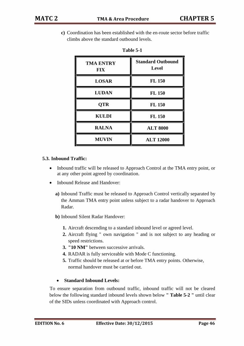
MATC 2 TMA & Area Procedure CHAPTER 5
EDITION No. 6 Effective Date: 30/12/2015 Page 46
c) Coordination has been established with the en-route sector before traffic
climbs above the standard outbound levels.
Table 5-1
TMA ENTRY
FIX
Standard Outbound
Level
LOSAR FL 150
LUDAN
FL 150
QTR
FL 150
KULDI
FL 150
RALNA
ALT 8000
MUVIN
ALT 12000
5.3. Inbound Traffic:
Inbound traffic will be released to Approach Control at the TMA entry point, or
at any other point agreed by coordination.
Inbound Release and Handover:
a) Inbound Traffic must be released to Approach Control vertically separated by
the Amman TMA entry point unless subject to a radar handover to Approach
Radar.
b) Inbound Silent Radar Handover:
1. Aircraft descending to a standard inbound level or agreed level.
2. Aircraft flying " own navigation " and is not subject to any heading or
speed restrictions.
3. "10 NM" between successive arrivals.
4. RADAR is fully serviceable with Mode C functioning.
5. Traffic should be released at or before TMA entry points. Otherwise,
normal handover must be carried out.
Standard Inbound Levels:
To ensure separation from outbound traffic, inbound traffic will not be cleared
below the following standard inbound levels shown below " Table 5-2 " until clear
of the SIDs unless coordinated with Approach control.
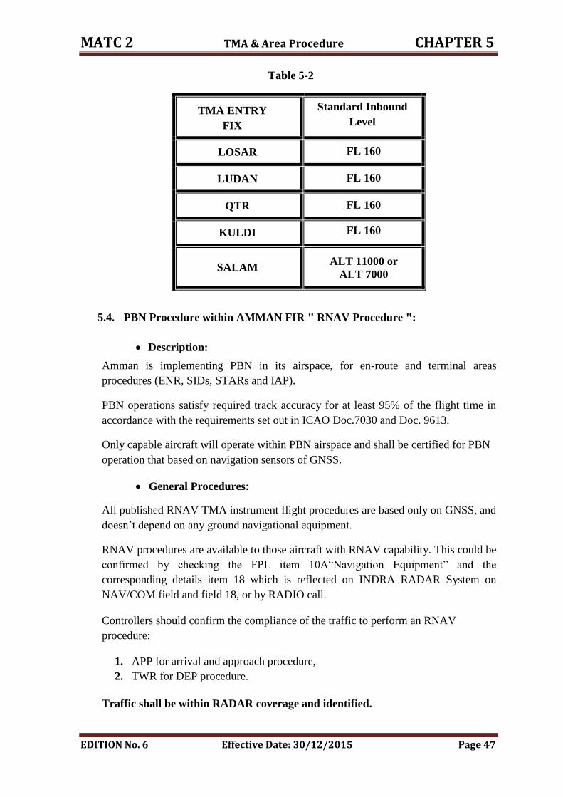
MATC 2 TMA & Area Procedure CHAPTER 5
EDITION No. 6 Effective Date: 30/12/2015 Page 47
Table 5-2
TMA ENTRY
FIX
Standard Inbound
Level
LOSAR FL 160
LUDAN
FL 160
QTR
FL 160
KULDI
FL 160
SALAM
ALT 11000 or
ALT 7000
5.4. PBN Procedure within AMMAN FIR " RNAV Procedure ":
Description:
Amman is implementing PBN in its airspace, for en-route and terminal areas
procedures (ENR, SIDs, STARs and IAP).
PBN operations satisfy required track accuracy for at least 95% of the flight time in
accordance with the requirements set out in ICAO Doc.7030 and Doc. 9613.
Only capable aircraft will operate within PBN airspace and shall be certified for PBN
operation that based on navigation sensors of GNSS.
General Procedures:
All published RNAV TMA instrument flight procedures are based only on GNSS, and
doesn’t depend on any ground navigational equipment.
RNAV procedures are available to those aircraft with RNAV capability. This could be
confirmed by checking the FPL item 10A“Navigation Equipment” and the
corresponding details item 18 which is reflected on INDRA RADAR System on
NAV/COM field and field 18, or by RADIO call.
Controllers should confirm the compliance of the traffic to perform an RNAV
procedure:
1. APP for arrival and approach procedure,
2. TWR for DEP procedure.
Traffic shall be within RADAR coverage and identified.
MATC 2 TMA & Area Procedure CHAPTER 5
EDITION No. 6 Effective Date: 30/12/2015 Page 48
Traffic could be vectored prior to the IAFs (Initial Approach Fixes) for sequencing
purposes, considering the Surveillance Minimum Altitude chart (SMA), and then
cleared to resume navigation to the IAF for either to continue the RNAV Approach or
to enter the associated holding pattern for further delaying actions, further more
traffic could be vectored to the IFs (Intermediate Fixes) directly.
In case of any failure of the GNSS system reported or performance degradation below
the required navigation performance, the APP controller will carry on an alternative
mean of navigation; subsequent ATC action will take place with the respect to the
nature of the failure to other traffic and to over all traffic situation and might revert to
a conventional means of navigation, phraseology to be used to indicate deficiency of
GNSS system:
1. GNSS REPORTED UNRELIABLE (or GNSS MAY NOT BE AVAILABLE
[DUE TO INTERFERENCE]);
2. IN THE VICINITY OF (location) (radius) [BETWEEN (levels)]; or IN THE
AREA OF (description) (or IN (name) FIR) [BETWEEN (levels)];
3. BASIC GNSS UNAVAILABLE FOR(specify operation) [FROM (time) TO
(time) (or UNTIL FURTHER NOTICE)]; ) BASIC GNSS UNAVAILABLE
[DUE TO (reason, e.g. LOSS OF RAIM or RAIM ALERT)];
4. UNABLE RNP (specify type) (or RNAV) [DUE TO (reason, e.g. LOSS OF
RAIM or RAIM ALERT)].
In reference to PBN applications in Amman FIR as a supplemental mean of
navigation, most of commercial aircraft found to be able to comply with RNAV SIDs
and STARs, and prefer to follow these procedures as published;
5.5. Holding Areas:
AMN VOR Hold:
Holding fix AMN VOR
Inbound R241 (track 061o)
Turns direction Left
Outbound 1 MIN
MHA 6000 FT
Maximum holding level 13000 FT
QAA VOR "LOW LEVEL Hold":
Holding fix QAA VOR
Inbound R077 (track 257o)
Turns direction Right
Outbound 1 MIN
Minimum holding level 6000 FT
Maximum holding level FL 180
MATC 2 TMA & Area Procedure CHAPTER 5
EDITION No. 6 Effective Date: 30/12/2015 Page 49
QAA VOR "HIGH LEVEL Hold":
Holding fix QAA VOR
Inbound R189 (track 009o)
Turns direction Right
Outbound 1 MIN
Minimum holding level FL 190
Maximum holding level FL 300
QTR VOR Hold :
Holding fix QTR VOR
Inbound R081 (track 261o)
Turns direction Right
Outbound 1 MIN
Minimum holding level 9000 FT
Inbound QTR R261; turn right, outbound for one-minute.
Minimum Holding Level 9000 FT ALT.
Maximum Holding Level FL180.
NOTE: Holding must be contained within 15NM to the East of QTR for
separation purposes.
MDB NDB / QAA DME Hold:
Holding fix MDB NDB
Inbound bearing 077 (track 077o)
Turns direction Right
Outbound 1 MIN
Minimum holding level 6000 FT
Maximum holding level 11000 FT
Inbound MDB track 077, turn right, outbound for one minute.
Minimum Holding Level 6000 FT.
Maximum Holding Level 11000 FT.
BAKIR FIX Hold:
Holding fix BAKER (AQB R042 07NM)
Inbound R042 (track 222o)
Turns direction Left
Outbound 1 MIN
Minimum holding level 8000 FT
Maximum holding level FL 180
Emergency holding level 7000 FT
MATC 2 TMA & Area Procedure CHAPTER 5
EDITION No. 6 Effective Date: 30/12/2015 Page 50
Restriction:
The hold must be contained within Aqaba APP Control Area boundaries, and
associated hold shall serve traffic proceeding to or departing from Aqaba/King
Hussein International Aerodrome.
BAKIR FIX: 293930N 0350530E, AQB R042-07NM, QTR R206-107NM.
METSA to BAKIR Track 206 -14NM.
NOTES:
1. Pilots are requested to relay their messages to King Hussein Tower on FREQ
118.1 or 119.2MHz whenever they are unable to maintain two ways
communication with Amman Terminal Area Control Center (TACC).
2. All operations below 7000FT ALT will be in accordance with Visual Flight
Rules, and controlled by King Hussein Tower within CTR and controlled by
Aqaba Approach within CTA.
Separation between holding areas:
Holds Altitude
AMN – QAA
MAX ALT 13000
JYO - QAA
MAX ALT 13000
AMN - QA
MAX ALT 13000
MDB - QAA
MAX ALT 11000
MDB - QAA
MAX ALT 11000
AMN - MDB
MAX ALT 11000
MDB – QTR
MAX ALT 11000
MDB – QA
MAX 6000'
QTR – QAA
MAX FL180
QTR – QA
MAX FL180
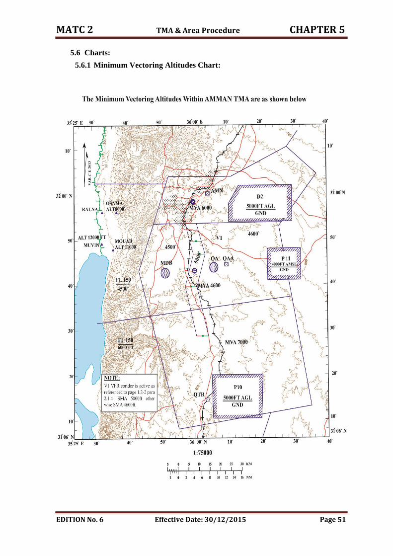
MATC 2 TMA & Area Procedure CHAPTER 5
EDITION No. 6 Effective Date: 30/12/2015 Page 51
5.6 Charts:
5.6.1 Minimum Vectoring Altitudes Chart:
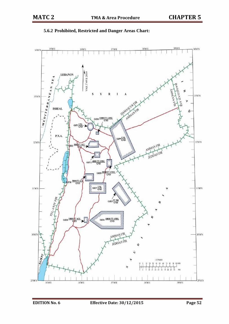
MATC 2 TMA & Area Procedure CHAPTER 5
EDITION No. 6 Effective Date: 30/12/2015 Page 52
5.6.2 Prohibited, Restricted and Danger Areas Chart:
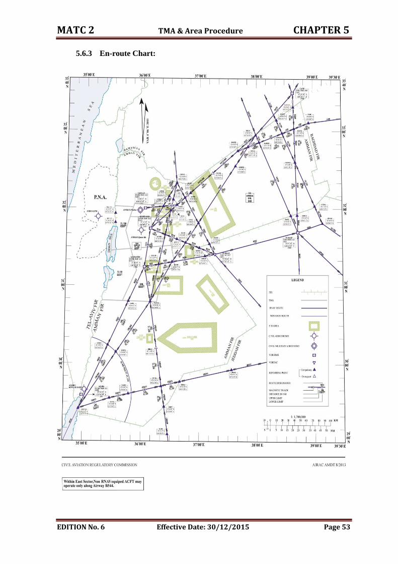
MATC 2 TMA & Area Procedure CHAPTER 5
EDITION No. 6 Effective Date: 30/12/2015 Page 53
5.6.3 En-route Chart:
CHAPTER SIX
Amman / Marka Airport Procedures
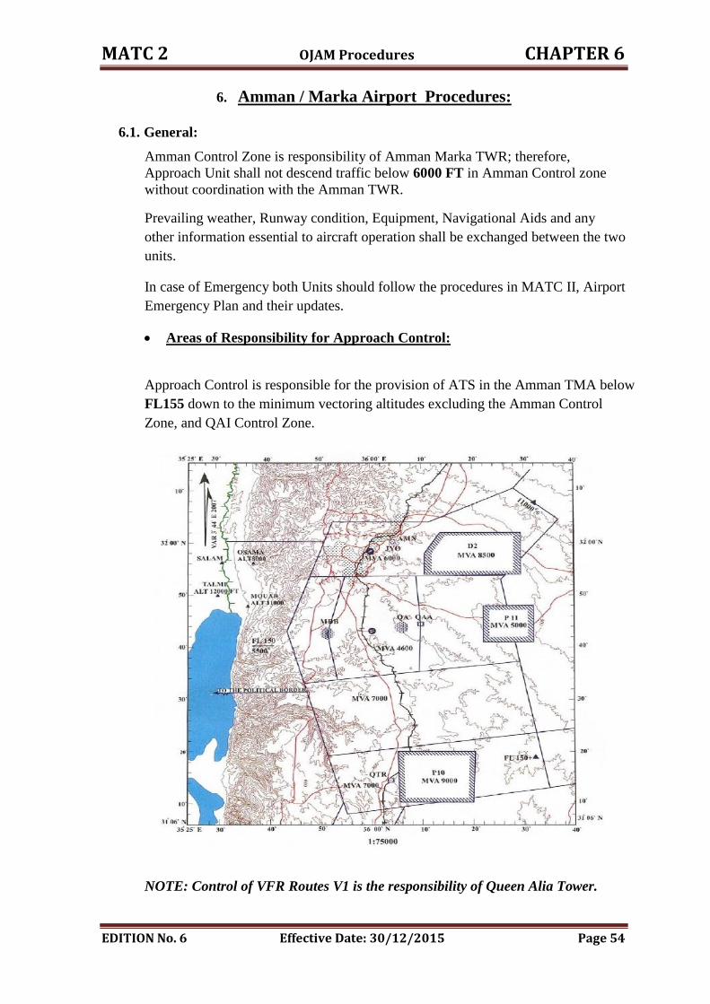
MATC 2 OJAM Procedures CHAPTER 6
EDITION No. 6 Effective Date: 30/12/2015 Page 54
6. Amman / Marka Airport Procedures:
6.1. General:
Amman Control Zone is responsibility of Amman Marka TWR; therefore,
Approach Unit shall not descend traffic below 6000 FT in Amman Control zone
without coordination with the Amman TWR.
Prevailing weather, Runway condition, Equipment, Navigational Aids and any
other information essential to aircraft operation shall be exchanged between the two
units.
In case of Emergency both Units should follow the procedures in MATC II, Airport
Emergency Plan and their updates.
Areas of Responsibility for Approach Control:
Approach Control is responsible for the provision of ATS in the Amman TMA below
FL155 down to the minimum vectoring altitudes excluding the Amman Control
Zone, and QAI Control Zone.
NOTE: Control of VFR Routes V1 is the responsibility of Queen Alia Tower.
MATC 2 OJAM Procedures CHAPTER 6
EDITION No. 6 Effective Date: 30/12/2015 Page 55
Areas of Responsibility for AMMAN / MARKA Tower:
Tower control is responsible for the provision of Air Traffic Services in Amman
Control Zone.
For light aircraft and military fixed wings:
1. South bound ( 4000 FT QNH ).
2. North bound ( 4500 FT QNH ).
For helicopters north and south bound ( 3500 FT QNH ).
6.2. Co-ordination Procedures :
6.2.1 General and Flight planning:
Safety and expedition are the prime responsibilities of both ATC units.
Adequate coordination between ATC units is to be maintained to ensure
continuity in service and a safe, expeditious flow of air traffic.
When attempting to increase expedition, consideration must always be given to
the possible detrimental effect on safety.
Where controllers work together, every effort should be made to monitor each
other's actions, thus providing an additional safeguard against errors or
omissions.
A controlled flight shall be under the control of ONLY ONE air traffic
control unit at any given time.
The Approach controller is responsible for coordination of IFR and controlled
VFR flights inbound and outbound to his Area of responsibility specified in
7.1 above with AMMAN / Marka Tower.
TWR is responsible for:
1. Modifying and updating the departure FPL according to the ATC clearance.
2. Creating any departure flight plan from Amman / Marka Airport which is
not available or lost from the RADAR system for any reason.
APP is responsible for any modification in the "Q Summary" in FDDs.
6.2.2 Departure Flights Procedure :
Ground controller shall request startup clearance from APP Unit for all departing
IFR. APP will issue ATC clearances as early as practicable, and it shall include:
1. SID designators " Conventional or RNAV ".
2. Standard outbound level or a lower level if required.
3. Any other restrictions such as "take-off time".
4. Any other information or restrictions such as "SSR code, level restrictions,
speed or rate of climb restrictions…".
Traffic proceeding via RALNA or MUVIN SIDs, APP will request SSR code and
QNH from Tel Aviv and pass it to the TWR as soon as possible.
MATC 2 OJAM Procedures CHAPTER 6
EDITION No. 6 Effective Date: 30/12/2015 Page 56
TWR shall obtain release clearance from APP unit for all departing IFR traffic.
APP shall release traffic for departure subject to traffic situation.
TWR shall release departing traffic to APP control as soon as possible when clear
from aerodrome traffic, or as follows:
1. Passing 5000 FT.
2. Immediately after airborne when IMC prevails or entering IMC.
3. When requested by APP as soon as possible after it is clear from circuit
traffic.
Academy Traffic requesting to proceed IFR to QTR hold, JAFER Airbase or
AQABA should submit flight plan and to follow standard instrument departure.
(Check Point 6.5).
Tower shall coordinate SVFR with Approach Unit.
6.2.3 Arrival Flights Procedure :
1. INDRA RADAR system will automatically print and indicate in the inbound
list in the TWR, all inbound estimates in sufficient time prior to the ETA.
2. In case INDRA RADAR system is unserviceable. APP shall pass EAT to the
TWR 15 MIN earlier; any revision more than 3 min shall be passed.
3. APP controller will pass Tower check before the release of traffic.
4. Revision more than 3 minutes, when radar is in use Tower check will be
done, when the aircraft is 20 NM from touchdown for straight-in approach
and 10 NM on localizer for release.
5. Any other information requested shall be passed as soon as possible, like:
POB, reason of flight.
APP shall release arrival traffic to AMM TWR, when:
1. Out bound AMN, leaving 6000 FT on the instrument approach.
2. On straight in approach 10 NM from touchdown.
3. In poor weather condition traffic will not be released until " field or runway "
is in sight.
4. If IMC prevails, after landing.
5. In visual approach the traffic will maintain 6000 FT and TWR will advise
6000 FT vacant released to TWR after passing 5 DME AMN.
6. Where else agreed in coordination.
NOTE: In IMC, TWR will issue the landing clearance –when appropriate-
through the APP, APP will pass it to the traffic and keeps monitoring it
until the minima.
6.2.4 RNAV Arrival Procedures:
APP should perform the following, beside the tasks that already agreed in the LoAs:
MATC 2 OJAM Procedures CHAPTER 6
EDITION No. 6 Effective Date: 30/12/2015 Page 57
1. All traffic is assumed to use conventional instrument approach (from AMN)
unless APP advices the TWR otherwise, as the majority of Amman MARKA
traffic complies only with conventional procedures only.
2. If the traffic is commencing an RNAV Approach, APP controller should pass
this information to the TWR as soon as possible, not later than IAFs (IVADO,
LOXER, MUSAL and EMILO).
3. Tower check is required shortly prior the traffic leave’s the IAFs (IVADO,
LOXER, MUSAL, EMILO).
4. APP will release the traffic to the TWR on final approach track, in these cases:
a) Passing waypoint NIVLU.
b) Passing waypoint SOLOL.
5. Landing interval for successive inbound traffic for both RWYs is: 10NM.
6. In case of traffic cleared to enter MUSAL hold either for the APP RWY06 or
Missed APP RWY24, coordination shall take place with the ADOC by APP. As
the holding pattern could extend outside the TMA to the north.
7. MUSAL – EMILO holds are considered as one hold, traffic in these holding
patterns shall be vertically separated from each other.
8. EMILO – RESOS holds are considered as one hold, traffic in these holding
patterns shall be vertically separated from each other.
NOTE:
1. In case of RWY24 is in use, traffic should be at NIVLU at 7200 ft descending,
APP will keep monitoring the traffic until it clears 6000ft descending.
2. In case of RWY06 is in use, traffic should be at SOLOL at 5500ft descending.
3. If the traffic is performing RNAV RWY24 APP via IVADO, close
coordination shall take place between the two units as this procedure has no
holding pattern fits, and this traffic shall be cleared for the approach upon
reaching IVADO.
4. If case of missed approach, TWR shall clear the missed approach path from
any other traffic may be operating in the vicinity of the aerodrome, and shall
advice APP immediately.
6.2.5 Visual Approach:
Visual approach may only be approved when requested by the pilot provided that:
1. The aircraft is number one for Approach.
2. The controller is satisfied that a visual Approach is acceptable in the
prevailing traffic and possible in prevailing weather.
3. Coordination is affected with TWR.
MATC 2 OJAM Procedures CHAPTER 6
EDITION No. 6 Effective Date: 30/12/2015 Page 58
4. Aircraft will maintain 6000 FT until descended by the TWR and TWR will
advice 6000 FT vacant to Approach Unit.
5. Traffic will be released to TWR after passing 5 DME AMN or having
" airfield or runway" in sight and clear from APP traffic.
NOTE: Succeeding arrival traffic will not be cleared for visual approach until
preceding one is landed or landing is assured, and each request for visual
approach will be handled individually (traffic shall not be sequenced behind
each other as they might loss visual contact).
Radar Vectoring for Visual Approach:
Upon pilot request radar vectoring for visual approach may be applied in which
the ATC is required to bring the aircraft to a point where the pilot can see the
runway , then will continue visually provided that:
a) ATC may initiate radar vectoring for visual approach provided the
reported ceiling is above the minimum altitude applicable to radar
vectoring and metrological conditions are such that, with reasonable
assurance, a visual approach and landing can be completed.
b) Clearance for visual approach shall be issued only after the pilot has
reported the aerodrome insight, at which time radar vectoring would
normally be terminated, successive arriving aircraft would be cleared for
visual approach with landing interval according to Paragraph 6.2.3.
6.3. Landing Intervals:
For conventional instrument approaches:
1. 7 minutes procedural, RWY 24 in use.
2. 5 minutes when RADAR in use, RWY 24 in use.
3. 10 minutes procedural or RWY 06 in use.
4. Or as coordinated.
For straight-in approaches:
1. 10 NM provided RADAR in use.
2. 20 NM procedural.
3. Or as coordinated.
NOTE: Priority will be given for arrival traffic over the departure, except for
VIP flight and for those which are experiencing weather deterioration and up
normal situations, Such as (certain military flights, urgent ambulance etc.
Succeeding aircraft will be released for Amman tower when preceding aircraft is:
1. RWY 24: Passing VOR in bound.
2. RWY 06: Traffic in base leg and landing is assured.
3. Or as coordinated.
MATC 2 OJAM Procedures CHAPTER 6
EDITION No. 6 Effective Date: 30/12/2015 Page 59
6.4. Runway Change:
1. Runway change will be initiated by Amman / Marka Tower.
2. Coordination will be effected with Approach.
3. Runway changes will take-effect immediately when traffic situation permits.
4. ATC clearances for departure traffic should be revised.
5. Alternative course of action will be considered, if so required, but if the wind
component urged, the change of the runway would normally occur, arrivals
will be subject to delay action.
NOTE:
1. Tailwind component shall not exceed 5 KTS. lCAO doe 4444.
2. When the crosswind component, including gusts, exceeds 28 km/h
(15 KTS), or the tailwind component, including gusts, exceeds 9 km/h
(5KTS).
3. Tailwind shall not exceed more than 5 KTS, when nomination runway
in use, if the tailwind is more than 5 KTS and less than 10 KTS it should be
pilot request and his responsibilities to use runway other than runway in use,
if the traffic permits, when the tail wind is more than 10 KTS its forbidden
and the main RWY for operation is the one its QFU is against wind direction.
4. Crosswind component shall not exceed l0 KTS according to the table and
lCAO Doe 4444. With pilot approval.
6.5. Training Flights:
IFR Training request standard SID to QTR hold, JAFER Airbase or AQABA will
be approved subject to traffic situation, considering the following:
1. QTR hold shall not exceed 3 Aircraft at the same time.
2. Practicing Instrument approaches will only be permitted if it does not cause
delay to IFR traffic.
The use of 5000 FT shall be approved by Approach Unit for practicing instrument
approaches.
Coordination between the Approach Unit and TWR as appropriate shall be effected
also in the following cases:
1. Aerobatics and parachute jumping.
2. Suspension of VFR.
3. Operation of SVFR.
4. Night flying.
5. Glider operation.
6. Military exercises, or special operations.
7. Recall of academy flights due to deteriorating weather conditions.
Air force traffic joining from the North or from the East requesting straight in
approach, shall be coordinated between the two ATC units, Amman tower and
Approach Unit.
MATC 2 OJAM Procedures CHAPTER 6
EDITION No. 6 Effective Date: 30/12/2015 Page 60
6.6. VFR and SVFR procedures:
It is the direct responsibility of the pilot using VFR corridor V1 to avoid collision
with other Aircraft and maintain VFR.
Operating Rules:
Pilots are required to comply with the following operating rules:
1. Maintain VMC.
2. Maintain a continuous listening watch on the required ATC frequency.
3. Make Visual position reports at the mandatory reporting points.
4. Follow ATC instructions.
5. Advice ATC if unable to comply with ATC instructions.
6. Pass "Operation Normal" reports to Queen Alia Control Tower every 15
minutes while operating within the training area.
Visual Flight Rules:
a) VFR flights shall not be operated:
1. Between 30 minutes after Sunset until 30 minutes before Sunrise.
2. Above FL 150.
b) Night VFR Flights within Amman/Marka Airport may be authorized by
CARC CEO provided that;
1. VFR minimum exists in the aerodrome traffic circuit.
2. Only 3 Aircraft are cleared for night flying in the circuit and 2 Helicopters.
3. At least 48 hours notice is provided.
SVFR at Amman / Marka CTR:
SVFR flights may be authorized to operate locally within a Control Zone, enter a
Control Zone for the purpose of landing , take off and depart from a Control Zone
provided that :
1. Ground visibility is not less than 1500 meter.
2. Traffic condition permit.
3. Approval from Approach Unit " request shall be handled individually " .
4. The aircraft is equipped with two way radio communications.
5. Aircraft is equipped with serviceable transponder.
6. None instrument licensed pilot is not permitted to fly SVFR.
7. FPL shall be submitted to ATS reporting office at least 15 minutes before
EOBT.
8. SVFR should be clear of clouds.
9. Clearance to aircraft will be issued as follows:
"CLEARED TO ENTER CONTROL ZONE BOUNDARY SVFR MAINTAIN
CLEAR OF CLOUDS AND IN SIGHT OF THE SURFACE."
MATC 2 OJAM Procedures CHAPTER 6
EDITION No. 6 Effective Date: 30/12/2015 Page 61
6.7 Diversion Procedure:
In case of any traffic request to divert to Amman / Marka Airport, the RADAR
Controller should:
1. Inform Amman Tower stating the diversion reason and diverted flight
information.
2. The Tower controller should inform the APP unit if this flight has a valid
landing permission or not.
3. Any other essential information.
6.8 Emergency Procedures:
Refer to MATC II and Airport EMR Plan and their amendments.
An incident report shall be filled by the unit in which the incident took place in its
area of responsibility.
TACC supervisor shall inform DANS; DANS will inform the concerned at Safety
Departments " Investigation, Airworthiness, and Aircraft Operation " accordingly.
Tower supervisor shall inform TACC about the following cases:
1. Local standby.
2. Full emergency.
3. Aircraft accident.
4. Weather standby.
5. Hi-jacking or bomb threat.
6. Strayed aircraft, overdue position report.
The message will contain the following details:
1. Type of the case.
2. Aircraft call sign and type.
3. Nature of flight " DEP , ARR , Circuit …….etc ".
4. ETA " for local traffic ".
5. Time of accident.
6. Position of accident.
7. When normal operation is resumed.
6.9 Fuel Dumping:
This procedure for any inbound or outbound traffic, the ATC should implement the
following:
1. Fuel Dumping will be carried out in QTR VOR at 9000 FT.
2. Vertical separation at least 2000 FT below and 1000 FT above the aircraft
dumping fuel.
3. ATC shall pass all necessary instructions prior to the commencement of Fuel
Dumping Operation " no contact with the flight during fuel dumping ".
MATC 2 OJAM Procedures CHAPTER 6
EDITION No. 6 Effective Date: 30/12/2015 Page 62
4. TWR ATC shall inform Amman TACC and ADOC.
5. The pilot should report the duration of the fuel dumping.
6.10 Miscellaneous Operations:
The following information shall immediately be coordinated between Queen
Tower and Approach Unit:
1. Missed approach.
2. Diversion.
3. Closure of the airport.
4. Fuel Spillage.
5. Maneuvering area situation.
6. Bird concentration.
7. Runway condition, Status of equipment, if degraded.
8. NOTAM.
9. Equipment status.
10. Any other relevant information.
Communication between the APP controller and Tower controller shall be
carried out by any means of:
1. Direct Lines Available.
2. AFTN When necessary.
3. Other means available.
6.11 Approach Procedure:
Instrument Approach/Missed Approach Procedures, Amman/Marka
International Airport (OJAM)
Aerodrome elevation: 2556 FT,
RWY 24 THR ELEV: 2459 FT,
RWY 06 THR ELEV: 2556 FT,
MSA: 5400FT, 25NM FROM ARP.
CIRCLING: All aircraft types 4000 FT (1445FT QFE), both RWYs.
6.11.1 Runway 24 :
ILS RWY 24:
When cleared for the approach, commence a 45o / 180
o procedure turn from AMN
to establish the ILS as follows:
- Outbound AMN R061, for 1 MIN. (AMN 03 DME), descend to 4600 FT.
- Turn right 45o, track 106
o, for 1 MIN.
- Turn left 180o to establish ILS RWY 24. Descend on the glide path to DA/H
ALT (Height)
FT Initial Approach Altitude 6000
Minimum Holding Altitude 6000
MATC 2 OJAM Procedures CHAPTER 6
EDITION No. 6 Effective Date: 30/12/2015 Page 63
VOR RWY 24:
When cleared for the approach, commence a 45o / 180
o procedure turn from AMN
to establish the inbound track as follows:
- Outbound AMN R061, for 1 MIN. (AMN 03 DME), descend to 4600FT.
- Turn right 45o, track 106
o, for 1 MIN.
- Turn left 180o to intercept AMN R061 inbound.
- After passing AMN continue on AMN R241, descend to MDA.
ALT (Height) FT
Minimum Holding Altitude 6000
Initial Approach Altitude 6000
Descend in procedure turn to 4600 (2142)
SDF AMN 3.55 DME 4600 (2142)
SDF AMN 3650 (1190)
MDA 3260 (802)
Missed Approach RWY 24:
Aircraft initiating missed approach will climb on RWY heading to 5000FT (2542FT
QFE) then turn right to 360˚ and contact ATC for further instructions.
6.11.2 Runway 06 :
VOR RWY 06:
When cleared for approach, leave AMN VOR on outbound Radial 061 after one minute
(03 DME), Commence procedure turn, turn right continue descent to intermediate
approach altitude to intercept radial 061 inbound to AMN VOR after passing AMN /
VOR break to right to join left hand down wind (circle to land left base ).
Descend in procedure turn to 4600 (2142)
No GP (LOC ONLY) Cross AMN (3.4
NM TCH)
3650 (1190)
MDA 2850 (392)
DA/H A B C D
straight-in CAT 1
Approach
2728(270) 2738(280) 2748(290) 2758(300)
No GP (LOC ONLY) 2848 (390)
Initial Approach Altitude 6000 FT ALT
Minimum Holding Altitude 6000 FT ALT
Descend in procedure turn to 4600 FT ALT (2142 FT QFE)
AMN/VOR 4000 FT ALT (1192 QFE)
CHAPTER SEVEN
Queen Alia Airport Procedures
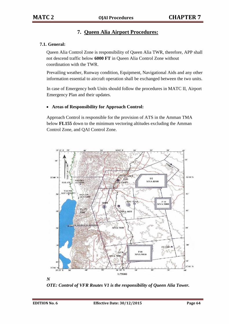
MATC 2 OJAI Procedures CHAPTER 7
EDITION No. 6 Effective Date: 30/12/2015 Page 64
7. Queen Alia Airport Procedures:
7.1. General:
Queen Alia Control Zone is responsibility of Queen Alia TWR, therefore, APP shall
not descend traffic below 6000 FT in Queen Alia Control Zone without
coordination with the TWR.
Prevailing weather, Runway condition, Equipment, Navigational Aids and any other
information essential to aircraft operation shall be exchanged between the two units.
In case of Emergency both Units should follow the procedures in MATC II, Airport
Emergency Plan and their updates.
Areas of Responsibility for Approach Control:
Approach Control is responsible for the provision of ATS in the Amman TMA
below FL155 down to the minimum vectoring altitudes excluding the Amman
Control Zone, and QAI Control Zone.
N
OTE: Control of VFR Routes V1 is the responsibility of Queen Alia Tower.
MATC 2 OJAI Procedures CHAPTER 7
EDITION No. 6 Effective Date: 30/12/2015 Page 65
Areas of Responsibility for Queen Alia Tower:
Tower control is responsible for the provision of Air Traffic Services in Queen Alia
Control Zone.
For light aircraft and military fixed wings:
1. South bound ( 4000 FT QNH ).
2. North bound ( 4500 FT QNH ).
For helicopters north and south bound ( 3500 FT QNH ) or as coordinated.
7.2. Co-ordination Procedures :
7.2.1 General and Flight planning:
Safety and expedition are the prime responsibilities of both ATC units.
Adequate coordination between ATC units is to be maintained to ensure
continuity in service and a safe, expeditious flow of air traffic.
When attempting to increase expedition, consideration must always be given to
the possible detrimental effect on safety.
Where controllers work together, every effort should be made to monitor each
other's actions, thus providing an additional safeguard against errors or omissions.
A controlled flight shall be under the control of ONLY ONE air traffic control
unit at any given time.
The Approach controller is responsible for coordination of IFR and controlled
VFR flights inbound and outbound to his Area of responsibility specified in 7.1
above with Queen Alia Tower.
TWR is responsible for:
1. Modifying and updating the departure FPL according to the ATC clearance.
2. Creating any departure flight plan from Queen Alia Airport which is not
available or lost from the RADAR system for any reason.
APP is responsible for any modification in the “Q Summary” in FDDs.
7.2.2 Departure Flights Procedure:
Ground controller shall request startup clearance from APP Unit for all departing
IFR. APP will issue ATC clearances as early as practicable, and it shall include:
1. SID designators " Conventional or RNAV ".
2. Standard outbound level or a lower level if required.
3. Any other restrictions such as "take-off time".
4. Any other information or restrictions such as “SSR code, level restrictions,
speed or rate of climb restrictions…".
Traffic proceeding via MOUAB or OSAMA SIDs, APP will request SSR code and
QNH from Tel Aviv and pass it to the TWR as soon as possible.
MATC 2 OJAI Procedures CHAPTER 7
EDITION No. 6 Effective Date: 30/12/2015 Page 66
TWR shall obtain release clearance from APP unit for all departing IFR traffic. APP
shall release traffic for departure subject to traffic situation.
TWR shall release departing traffic to APP control as soon as possible when clear
from aerodrome traffic, or as follows:
1. Passing 5000 FT.
2. Immediately after airborne when IMC prevails or entering IMC.
3. When requested by APP.
Airborne time shall be passed immediately to APP, when RADAR system is not
serviceable.
Before vectoring any departure traffic, APP will consider V1 corridor is active and
assure procedural separation unless otherwise coordinated.
7.2.3 Arrival Flights Procedure:
1. INDRA RADAR system will automatically print and indicate in the inbound
list in the TWR, all inbound estimates in sufficient time prior to the ETA.
2. In case INDRA RADAR system is unserviceable. APP shall pass EAT to the
TWR 15 MIN earlier; any revision more than 3 min shall be passed.
3. APP controller will pass Tower check before the release of traffic.
4. Any other information requested shall be passed as soon as possible, like: POB,
reason of flight.
5. Approach Unit passes final approach checks " TWR check, Sequence and
Revisions more than 3 minutes "
A special check of position will be made to the Tower either:
1. Beacon inbound " QAA or MDB ".
2. 8 - 10 NM when Radar is in use.
3. Before entering the aerodrome traffic area 5 NM for visual approach and
passing 6000 FT if RADAR is not in use.
APP shall release arrival traffic to Queen TWR when:
1. On final approach before QAA on westerly operation.
2. On final approach before MDB on easterly operation
3. In poor weather condition traffic will not be released until "airfield or runway"
is in sight.
4. If IMC prevails, after landing.
5. Down wind or base leg on visual approach or as coordinated.
6. Where else agreed in coordination
NOTE: in IMC, TWR will issue the landing clearance –when appropriate-
through the APP, APP will pass it to the traffic on final “When Having
MATC 2 OJAI Procedures CHAPTER 7
EDITION No. 6 Effective Date: 30/12/2015 Page 67
Runway Insight Cleared To Land, RWY in use, SURFACE WIND…” and
keeps monitoring it until the minima.
7.2.4 RNAV Arrival Procedures:
1. Tower check is to be made prior the traffic leaves IAFs as follows:
a) RWY 26R / 26L : ORDUN or ASPAL.
b) RWY 08R / 08L : LOTES or RESOS.
2. APP will release the traffic to the TWR after turning IFs (on final approach track) as
follows:
a) RWY 26L: GENIS.
b) RWY 26R: ENADA.
c) RWY 08L: OBSAL.
d) RWY 08R: GEVUP.
3. Landing interval for successive inbound traffic is 7 NM for all runways.
4. RESOS – LOTES holds are considered as one hold, traffic shall be vertically
separated.
5. ASPAL – ORDUN holds are considered as one hold, traffic shall be vertically
separated.
6. RESOS – EMILO holds are considered as one hold, traffic shall be vertically
separated.
7.2.5 Visual Approach:
Visual approach may only be approved when requested by the pilot provided that:
1. The aircraft is number one for the approach.
2. The controller is satisfied that a visual approach is acceptable in the prevailing
traffic situation and possible in the prevailing weather.
3. Coordination is effected with Tower.
4. Traffic will be cleared to the circuit altitude, within the aerodrome circuit area
and will be released to the tower as coordinated or having " airfield or
runway" in sight and clear from APP traffic.
NOTE: Succeeding arrival traffic will not be cleared for visual approach until
preceding one is landed, and each request for visual approach will be handled
individually.
RADAR Vectoring for Visual Approach:
Upon pilot request RADAR vectoring for visual approach, the RADAR
Controller is required to bring the aircraft to a point where the pilot can see the
runway , then will continue visually provided that:
MATC 2 OJAI Procedures CHAPTER 7
EDITION No. 6 Effective Date: 30/12/2015 Page 68
1. The RADAR controller may initiate RADAR vectoring for visual approach
provided the reported ceiling is above the minimum altitude applicable to
RADAR vectoring and metrological conditions are such that, with reasonable
assurance, a visual approach and landing can be completed.
2. Clearance for visual approach shall be issued only after the pilot has reported
the airfield or the runway is insight, at that time RADAR vectoring would
normally be terminated, successive arriving aircraft would be cleared for visual
approach after coordination with tower.
Visual approach on Westerly or Easterly operations:
1. Traffic on visual approach will be cleared down to the circuit altitude,
within the aerodrome traffic circuit, with no restriction to join base leg of
the runway in use except if there is traffic on V1 route.
2. Approach will release the traffic leaving the initial approach level/or the
minimum vectoring altitude (when radar in use), joining downwind or
base leg, as early as possible.
NOTE: Succeeding arrival traffic will not be cleared for visual approach until
preceding one is landed or landing is assured, and each request for visual
approach will be handled individually.
3. When the VFR corridor " V1 " is active, visual approach clearance will be
subject to close coordination and approval by the tower, considering traffic
situation within this corridor, such clearances will not be a matter of
dispute, but priority will be given to IFR traffic to the extent possible.
NOTE: Visual approach maybe approved via QAA or MDB if traffic permit's.
4. Tower will consider the precise estimation of arrival traffic inbound to
QAA & MDB, VFR traffic request VFR clearances, issuance of such, will
be based on the estimation of arrival traffic.
7.3 Landing Intervals:
RADAR is in Use:
1. Using the same runway 5 NM.
2. Using parallel runway 5 NM provided that the two runways are available, one for
departure and one for landing.
3. 5 NM separation for same runway maybe used in the following cases:
I. For runway 26L or 08L provided that two runways are available either
westerly or easterly operation.
II. If the preceding aircraft is a training aircraft for touch and go, succeeding one
will be separated by 5 NM behind, for the same runway, provided that
succeeding a/c performing same speed or less than the preceding aircraft.
MATC 2 OJAI Procedures CHAPTER 7
EDITION No. 6 Effective Date: 30/12/2015 Page 69
RADAR not AVAILABLE:
The landing interval for QAA VOR Procedure is 5 minutes; succeeding
aircraft will be cleared for Approach when the preceding aircraft is QAA
inbound leaving 4600 FT.
The landing interval for MDB NDB Procedure landing interval 5 minutes,
succeeding aircraft will be cleared for approach when the preceding aircraft
is MDB inbound on Final Approach passing 4500 FT.
7.4 Runway Change:
1. Runway change will be initiated by Queen Alia Tower.
2. Coordination will be effected with Approach.
3. Runway changes will take-effect when traffic situation permits.
4. ATC clearances for departure traffic should be revised.
5. Alternative course of action will be considered, if so required, but if the
wind component urged, the change of the runway would normally occur,
arrivals will be subject to delay action.
NOTE:
1. Tailwind component shall not exceed 5 KTS. lCAO doe 4444.
2. When the crosswind component, including gusts, exceeds 28 km/h
(15 KTS), or the tailwind component, including gusts, exceeds 9 km/h (5KTS).
3. Tailwind shall not exceed more than 5 KTS, when nomination runway
in use, if the tailwind is more than 5 KTS and less than 10 KTS it should be
pilot request and his responsibilities to use runway other than runway in use,
if the traffic permits, when the tail wind is more than 10 KTS its forbidden
and the main RWY for operation is the one its QFU is against wind direction.
4. Crosswind component shall not exceed l0 KTS according to the table and
lCAO Doe 4444. With pilot approval
7.5 Training Flights:
TWR shall coordinate all training operation in the circuit with Approach
control previously to avoid the peak landing hours.
Only one training aircraft allowed at the same time.
All training traffic in the circuit should use the block code 2402-2477.
Circuit direction is left-hand on the left runways " 26L / 08L " and right-
hand on the right runways " 26R / 08R ".
Circuit altitude for the training traffic at Queen Alia is 3500 FT QNH.
4000 FT QNH Circuit altitude for the training traffic at Queen Alia could be
permitted, prior coordination must be established between TWR & APP.
Training traffic carrying out IFR Approaches will be coordinated with TWR,
but normal retained back to the approach frequency.
MATC 2 OJAI Procedures CHAPTER 7
EDITION No. 6 Effective Date: 30/12/2015 Page 70
If there is any arriving aircraft within the TMA boundary, the training
aircraft will be released to the APP Control for sequencing.
7.6 VFR and SVFR Procedure:
It is the direct responsibility of the pilot using VFR corridor V1 to avoid collision
with other Aircraft and maintain VFR.
When the VFR corridor " V1 " is active, visual approach clearance will be subject
to close coordination and approval by the tower.
Operating Rules:
Pilots are required to comply with the following operating rules:
1. Maintain VMC.
2. Maintain a continuous listening watch on the required ATC frequency.
3. Make Visual position reports at the mandatory reporting points.
4. Follow ATC instructions.
5. Advice ATC if unable to comply with ATC instructions.
6. Pass "Operation Normal" reports to Queen Alia Control Tower every 15
minutes while operating within the training area.
Visual Flight Rules:
VFR flights shall not be operated:
1. Between 30 minutes after Sunset until 30 minutes before Sunrise.
2. Above FL 150.
Tower will consider the precise estimation of arrival traffic inbound to QAA
and MDB, VFR traffic request VFR clearances, will be based on the estimation
of arrival traffic.
Control of VFR Routes V1 is the responsibility of Queen Alia Tower.
SVFR at Queen Alia CTR :
SVFR flights may be authorized to operate locally within a Control Zone, enter a
Control Zone for the purpose of landing , take off and depart from a Control
Zone provided that :
1. Ground visibility is not less than 1500 meter.
2. Traffic condition permit.
3. Approval from Approach Unit " request shall be handled individually " .
4. The aircraft is equipped with two way radio communications.
5. Aircraft is equipped with serviceable transponder.
6. None instrument licensed pilot is not permitted to fly SVFR.
7. FPL shall be submitted to ATS reporting office at least 15 minutes before
EOBT.
8. SVFR should be clear of clouds.
MATC 2 OJAI Procedures CHAPTER 7
EDITION No. 6 Effective Date: 30/12/2015 Page 71
9. Clearance to aircraft will be issued as follows:
"CLEARED TO ENTER CONTROL ZONE BOUNDARY SVFR
MAINTAIN CLEAR OF CLOUDS AND IN SIGHT OF THE
SURFACE."
7.7 Diversion Procedure:
In case of any traffic request to divert to Queen Alia Airport, RADAR Controller
should:
1. Inform Queen Tower stating the diversion reason and diverted flight
information.
2. The Tower controller should inform the APP unit if this flight has a valid
landing permission or not.
3. Any other essential information.
7.8 Emergency Procedures:
Refer to MATC II and Airport EMR Plan and their amendments.
The incident report shall be filled by the unit in which the incident took place in
its area of responsibility.
The unit supervisor shall inform DANS; DANS will inform the concerned at
Safety departments " Investigation, Airworthiness, and Aircraft Operation "
accordingly.
Tower supervisor shall inform TACC about the following cases:
1. Local standby.
2. Full emergency.
3. Aircraft accident.
4. Weather standby.
5. Hi-jacking or bomb threat.
6. Strayed aircraft, overdue position report.
The message will contain the following details:
1. Type of the case.
2. Aircraft call sign and type.
3. Nature of flight " DEP , ARR , Circuit …….etc ".
4. ETA " for local traffic ".
5. Time of accident.
6. Position of accident.
7. When normal operation is resumed.
7.9 Fuel Dumping:
This procedure for any inbound or outbound traffic, the ATC should implement the
following:
MATC 2 OJAI Procedures CHAPTER 7
EDITION No. 6 Effective Date: 30/12/2015 Page 72
1. Fuel Dumping will be carried out in QTR VOR at 9000 FT.
2. Vertical separation at least 2000 FT below and 1000 FT above the aircraft
dumping fuel.
3. ATC shall pass all necessary instructions prior to the commencement of Fuel
Dumping Operation " no contact with the flight during fuel dumping ".
4. TWR ATC shall inform Amman TACC and ADOC.
5. The pilot should report the duration of the fuel dumping.
7.10 Miscellaneous Operations:
The following information shall immediately be coordinated between Queen
Tower and Approach Unit:
1. Missed approach.
2. Diversion.
3. Closure of the airport.
4. Fuel Spillage.
5. Maneuvering area situation.
6. Bird concentration.
7. Runway condition, Status of equipment, if degraded.
8. NOTAM.
9. Equipment status.
10. Any other relevant information.
Communication between the APP controller and Tower controller shall be
carried out by any means of:
1. Direct Lines Available.
2. AFTN When necessary.
3. Other means available.
7.11 Surveillance Radar Approach " SRA ":
Approach Unit will pass a Tower Check at 8 - 10 NM from touchdown and Tower
will issue a landing clearance, if possible, or instruct Approach to check at 4 NM.
The flight will be released to Tower when the SRA is completed at 2 NM. If a
landing clearance has not been received by 2 NM from touchdown, Approach will
instruct the flight to execute a Missed Approach and will inform Tower.
Due to approach segment of Runway 08R is not served with vertical and
horizontal guidance, and Weather deterioration within QAIA zone during winter
season, especially when the Cloud Base becomes below the minimum vectoring
altitude and the RVR reading is 350 m or could be more, SRAs procedure shall be
initiated by the Supervisor, this approach procedure is Non-precision
Approaches rely on the pilot being in a position to cross the published Final
Approach Fix at the specified altitude in order to safely complete the approach.
MATC 2 OJAI Procedures CHAPTER 7
EDITION No. 6 Effective Date: 30/12/2015 Page 73
Requirements:
1. SRAs may be carried out only where the ATS surveillance system and the
procedure have been approved by the Chief Commissioner of CARC to be
used only at Queen Alia international.
2. A waiver by his Excellency chief commissioner to include 12 ATC
personnel to conduct this kind of approach, qualification level is 25 runs on
the simulator, its validity for temporary duration such as six months,
starting 1st of November 2011 after the training assignment is achieved; this
task is considered to be one of the RADAR approach control duties.
3. Thales RADAR system enhances coverage on final approach08R till 2nm
from touchdown point. Final Approach Fix (FAF), will be located on the
extended center line of the runway 08R abeam MDB/NDB, 6.6nm from
touchdown zone, where the commencement of the SRA approaches, the
FAF point called IVELO and its coordinates are N 314145.5700
E0355113.8700.
4. This point will be displayed on the RADAR controller working position,
according to point No 4 related to the said procedure below.
Procedure:
1. Phraseology :
- Vectoring for surveillance RADAR approach; runway (08R).
- THIS WILL BE A SURVEILLANCE RADAR APPROACH RUNWAY
(number) TERMINATING AT (distance) FROM TOUCHDOWN,
OBSTACLE CLEARANCE ALTITUDE (or HEIGHT) (number) METRES
(or FEET) CHECK YOUR MINIMA [IN CASE OF GO AROUND
(instructions)];
- APPROACH INSTRUCTIONS WILL BE TERMINATED AT (distance)
FROM TOUCHDOWN.
- COMMENCE DESCENT NOW [TO MAINTAIN A (number) DEGREE
GLIDE PATH];
- (distance) FROM TOUCHDOWN ALTITUDE (or HEIGHT) SHOULD BE
(numbers and units).
- CHECK GEAR DOWN [AND LOCKED];
- REPORT RUNWAY [LIGHTS] IN SIGHT;
- APPROACH COMPLETED [CONTACT (unit)].
- HEADING IS GOOD;
- ON TRACK.
2. The following conditions apply to an SRA which terminates at 2 miles from
touchdown:
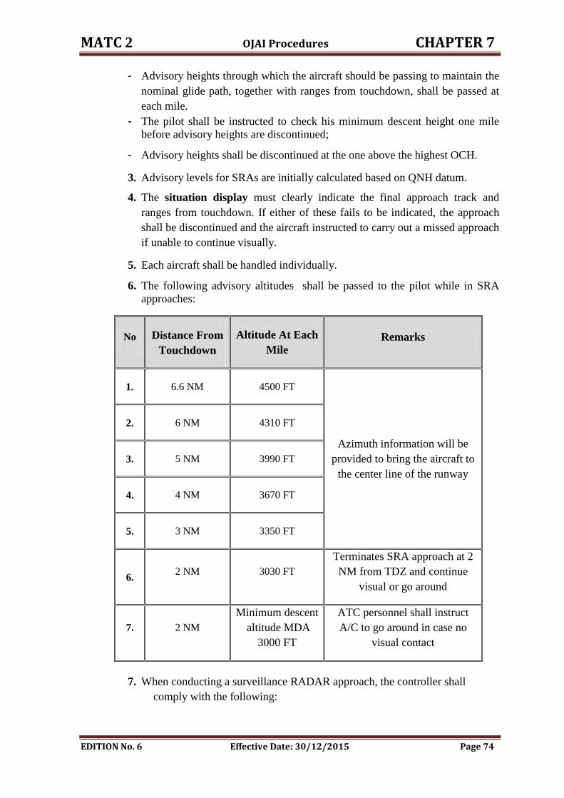
MATC 2 OJAI Procedures CHAPTER 7
EDITION No. 6 Effective Date: 30/12/2015 Page 74
- Advisory heights through which the aircraft should be passing to maintain the
nominal glide path, together with ranges from touchdown, shall be passed at
each mile.
- The pilot shall be instructed to check his minimum descent height one mile
before advisory heights are discontinued;
- Advisory heights shall be discontinued at the one above the highest OCH.
3. Advisory levels for SRAs are initially calculated based on QNH datum.
4. The situation display must clearly indicate the final approach track and
ranges from touchdown. If either of these fails to be indicated, the approach
shall be discontinued and the aircraft instructed to carry out a missed approach
if unable to continue visually.
5. Each aircraft shall be handled individually.
6. The following advisory altitudes shall be passed to the pilot while in SRA
approaches:
No Distance From
Touchdown
Altitude At Each
Mile
Remarks
1. 6.6 NM 4500 FT
Azimuth information will be
provided to bring the aircraft to
the center line of the runway
2. 6 NM 4310 FT
3. 5 NM 3990 FT
4. 4 NM 3670 FT
5. 3 NM 3350 FT
6. 2 NM 3030 FT
Terminates SRA approach at 2
NM from TDZ and continue
visual or go around
7. 2 NM
Minimum descent
altitude MDA
3000 FT
ATC personnel shall instruct
A/C to go around in case no
visual contact
7. When conducting a surveillance RADAR approach, the controller shall
comply with the following:

MATC 2 OJAI Procedures CHAPTER 7
EDITION No. 6 Effective Date: 30/12/2015 Page 75
a) At or before the commencement of the final approach, the aircraft shall be
informed of the point at which the surveillance RADAR approach will be
terminated.
b) The aircraft shall be informed when it is approaching the point at which it
is computed that descent should begin, and just before reaching that point it
shall be informed of the obstacle clearance altitude/height " 2960 FT " and
instructed to descend and check the applicable minima.
c) Azimuth instructions shall be given in accordance with the precision
approach technique and according to the following;
i. The pilot shall be informed at regular intervals of the aircraft’s
position in relation to the extended centre line of the runway.
ii. Heading corrections shall be given as necessary to bring the aircraft
back on to the extended centre line.
iii. In the case of azimuth deviations, the pilot should not take corrective
action unless specifically instructed to do so.
d) Distance from touchdown shall normally be passed at every 1NM.
e) Pre-computed levels through which the aircraft should be passing to
maintain the glide path shall also be transmitted at every each 1NM at the
same time as the distance.
f) The surveillance RADAR approach shall be terminated:
i. At a distance of (2 NM) from touchdown.
ii. Before the aircraft enters an area of continuous RADAR clutter.
iii. When the pilot reports that a visual approach can be affected;
whichever is the earliest.
g) Transmission should not be interrupted for intervals of more than five
seconds while the aircraft is within a distance of 8 km " 4 NM " from
touchdown.
h) The controller should not be responsible for any duties other than those
directly connected with a particular approach " SRA approach procedure ".
Contingency procedures " What If ", the SRA procedures are discontinued and
ATC priorities:
An aircraft shall be instructed to carry out a missed approach procedures in any of
the following circumstances:
1. On instructions from RADAR Approach or QAIA TWR.
2. When no landing clearance is received before 2 miles from touchdown (or
such other range agreed with QAIA TWR).
3. When it appears to be dangerously positioned on final approach in the
following Circumstances:
MATC 2 OJAI Procedures CHAPTER 7
EDITION No. 6 Effective Date: 30/12/2015 Page 76
a) If it reaches a position from which it appears that a successful approach
cannot be completed.
b) If it is not visible on the situation display for any significant interval
during the final approach track, especially the last two nautical miles
from the threshold of RW 08R.
c) If the position or identification of the aircraft is in doubt during any
portion of the final approach.
Missed approach instructions shall include the level 5000 FT to which the aircraft is
to climb and, if necessary, heading instructions to keep the aircraft within the
missed approach area.
The aircraft shall be instructed to contact QAIA TWR or by arrangement, to remain
with the approach RADAR controller.
When a RADAR approach cannot be continued due to any circumstances:
1. The amount of clutter.
2. Failure or malfunction of the ATS surveillance system .
3. The associated air-ground communications.
4. When the pilot reports that a visual approach can be affected.
The aircraft must be informed immediately.
Only small changes in heading are necessary to maintain the correct flight path,
minor changes in azimuth information.
Descent rate is not greater than 300 feet/mile.
Aircraft shall be vectored so as to be established on the final approach track at a
distance of not less than 8 miles from touchdown.
Aircraft shall be positioned so as to maintain a period of stabilized level flight
before commencing descent on the nominal descent path of a SRA.
Non-precision approaches for RW 08R does not incorporate ground-based
electronic descent guidance put include calculated glide path guidance of SRAs
approaches.
The aircraft is to be established on the final approach track before the Final
Approach Fix (IVELO) to enable it to cross the Final Approach Fix at the altitude
4500FT as specified in the notified procedure.
Aircraft carrying on SRA approaches will be vertically separated from traffic in
sequence waiting for approach, till the aircraft in the SRA operation has landed.
A separate frequency shall be used during the operation of SRA procedures.
Suspension of VFR and SVFR during the operation of SRA procedures.
NOTE: SRA is suspended until further notice.
MATC 2 OJAI Procedures CHAPTER 7
EDITION No. 6 Effective Date: 30/12/2015 Page 77
7.12 Approach Procedures:
INSTRUMENT APPROACH / MISSED APPROACH PROCEDURES,
QUEEN ALIA INTERNATIONAL AIRPORT (OJAI)
Aerodrome elevation 2397 FT,
RWY 26L THR ELEV: 2367 FT, RWY 26R THR ELEV: 2397 FT,
RWY 08L THR ELEV: 2362 FT, RWY 08R THR ELEV: 2359 FT,
MSA: 4900 FT, 25NM FROM ARP.
CIRCLING: All aircraft types 3500 FT (1105 FT QFE), All RWYs.
7.12.1 Runway 26L:
ILS RWY 26L:
When cleared for approach, descend in the QAA holding pattern to the
intermediate Approach Altitude and intercept the ILS on the inbound leg.
Descend on the Glide path to DA/H.
ALT (Height) FT
Minimum Holding Altitude 6000
Initial Approach Altitude 6000
Intermediate Approach 4600 (2235)
ILS DA/H 2567 (200)
SDF No Glide Path (LOC ONLY): 4NM to TCH
(3.4NM from QAA)
3600 (1233)
MDA/H No Glide Path (LOC ONLY) 2670 (303)
ILS RWY 26L CAT II:
When cleared for approach, descend in the QAA holding pattern to the
intermediate Approach Altitude and intercept the ILS on the inbound leg.
Descend on the Glide path to DA/H.
ALT (Height) FT
Minimum Holding Altitude 6000
Initial Approach Altitude 6000
Intermediate Approach 4600 (2235)
ILS DA/H 2507 (140)
MATC 2 OJAI Procedures CHAPTER 7
EDITION No. 6 Effective Date: 30/12/2015 Page 78
VOR RWY 26L :
When cleared for approach, descend in QAA holding pattern to the intermediate
altitude, Leave QAA on R257 (track 077o) to the THR 26L (QAA 7.3NM).
ALT (Height) FT
Minimum Holding Altitude 6000
Initial Approach Altitude 6000
Intermediate Approach 4600 (2235)
SDF: 4NM to TCH (3.4NM from
QAA)
3600 (1235)
MDA/H 2865 (500)
Visual Approach RWY 26L:
Visual Approach will be approved subject to Meteorological and traffic
condition, when requested by pilot. Initial clearance to descend to 4600FT ALT
will be given on passing 10d QAA.
Missed Approach RWY 26L:
Climb on RWY heading to 5000FT (QNH), Turn left to QAA or QA maintaining
5000FT (QNH) or as directed by ATC.
Restriction: Turn must be contained within TMA.
7.12.2 Runway 26R:
ILS RWY 26R:
When cleared for the approach, leave QAA, to establish QAA R050, to 6.5 NM,
descend to 4600FT, and turn right to establish the ILS RWY 26R.
Speed: 180 KTS or less.
ALT (Height) FT
Minimum Holding Altitude 6000
Initial Approach Altitude 6000
Intermediate Approach 4600 (2205)
ILS DA/H 2605 (210)
SDF No Glide Path (LOC ONLY): abeam QAA 4600 (2205)
SDF No Glide Path (LOC ONLY): 3.5 NM TCH 3400 (1003)
MDA/H No Glide Path (LOC ONLY) 2650 (255)
MATC 2 OJAI Procedures CHAPTER 7
EDITION No. 6 Effective Date: 30/12/2015 Page 79
Missed Approach Procedure: Climb RWY heading to 5000FT (QNH), turn
right, and proceed to QAA VOR maintaining 5000FT or as directed by ATC.
RESTRICTION: Turn must be contained within TMA.
Visual Approach RWY 26R:
Visual Approach will be approved subject to Meteorological and traffic
condition, when requested by pilot. Initial clearance to descend to 4600FT ALT
will be given on passing 10d QAA.
7.12.3 Runway 08 L :
ILS RWY 08L:
When cleared for the approach, descend in MDB holding pattern to the intermediate
approach altitude, intercept the ILS RWY 08L, descend to DH/A.
ALT (Height) FT
Minimum Holding Altitude 6000
Initial Approach Altitude 6000
Intermediate Approach 4500 (2150)
ILS DA/H 2610 (250)
MDA/H No Glide Path (LOC ONLY) 2940 (580)
NOTE: Parallel Instrument RWY is not applied.
NDB RWY 08L:
Overhead MDB NDB at 6000FT AMSL, fly outbound on track 257 DEG MAG
for one minute descending to 4500 FT, establish inbound track 077 DEG MAG to
MDB NDB, on passing MDB NDB, establish track 077 DEG MAG descending to
2960 (QNH).
Initial Approach Altitude 6000 FT (QNH).
Missed Approach RWY 08L:
Missed Approach point 11 DME QAA (4.6 NM from MDB NDB) climb straight
ahead to 5000FT(QNH) turn left to MDB/NDB maintaining 5000FT (QNH) or as
directed by ATC.
7.12.4 Runway 08 R:
NDB RWY 08R:
When cleared for the approach, descend in MDB holding pattern to the
intermediate approach altitude, leave MDB on bearing 276o (track 084
o) towards
the missed Approach point (5 NM MDB, 10.6 DME QAA), descend to MDA/H.
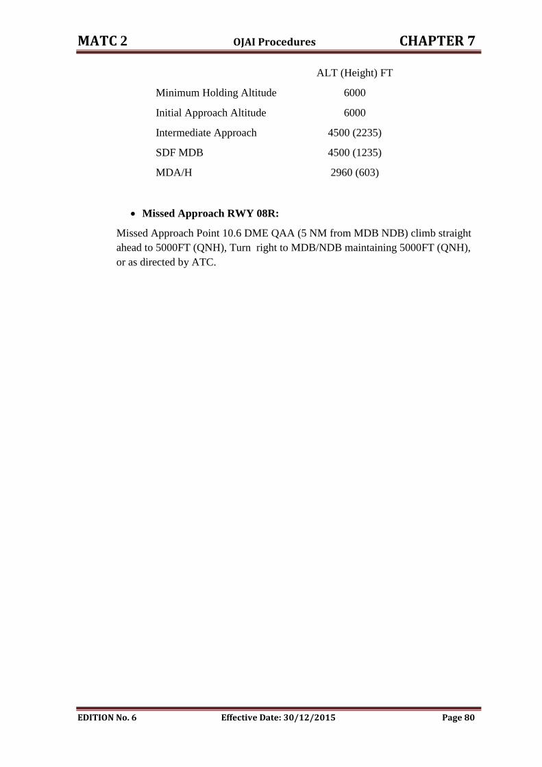
MATC 2 OJAI Procedures CHAPTER 7
EDITION No. 6 Effective Date: 30/12/2015 Page 80
ALT (Height) FT
Minimum Holding Altitude 6000
Initial Approach Altitude 6000
Intermediate Approach 4500 (2235)
SDF MDB 4500 (1235)
MDA/H 2960 (603)
Missed Approach RWY 08R:
Missed Approach Point 10.6 DME QAA (5 NM from MDB NDB) climb straight
ahead to 5000FT (QNH), Turn right to MDB/NDB maintaining 5000FT (QNH),
or as directed by ATC.
CHAPTER EIGHT
AQABA / King Hussein Airport Procedures
MATC 2 OJAQ PROCEDURES CHAPTER 8
EDITION No. 6 Effective Date: 30/12/2015 Page 81
8. AQABA / King Hussein Airport Procedures
8.1. General:
Aqaba approach control unit is responsible for the provision of ATS in the Aqaba
control area " CTA " SEMI-CIRCUIT, lateral limits is 45 NM from AQB/VOR and
the upper ceiling is FL 250 and lower limit is ALT 7000.
Traffic shall only be cleared on nonstandard SID's or Approach Procedures in the
following circumstances:
1. Emergency.
2. Medical Flights.
3. Military.
4. If RADAR service is provided.
5. Visual approach procedure when conditions permit.
8.2 Co-ordination Procedures :
8.2.1 General and Flight planning:
Safety and expedition are the prime responsibilities of both ATC units.
Adequate coordination between ATC units is to be maintained to ensure
continuity in service and a safe, expeditious flow of air traffic.
When attempting to increase expedition, consideration must always be given to
the possible detrimental effect on safety.
Where controllers work together, every effort should be made to monitor each
other's actions, thus providing an additional safeguard against errors or
omissions.
A controlled flight shall be under the control of ONLY ONE air traffic control
unit at any given time.
The Approach controller is responsible for coordination of IFR and controlled
VFR flights inbound and outbound to his Area of responsibility specified in
8.1 above with Aqaba Approach unit.
Aqaba Approach Unit is responsible for:
I. Modifying and updating the departure FPL according to the ATC clearance.
II. Creating any departure flight plan from King Hussein Airport which is not
available or lost from the RADAR system for any reason including all local
traffic which is following VFR corridors requesting to proceed to QTR,
Queen Alia or Amman Marka airports.
APP is responsible for any modification in the “Q Summary” in FDDs.
8.2.2 Departure Flights Procedures:
Aqaba Tower requests start up clearance from Aqaba APP for all departing TFC.
Aqaba Approach controller shall coordinate the start-up clearance with the
Amman TACC " West Sector " for approval.
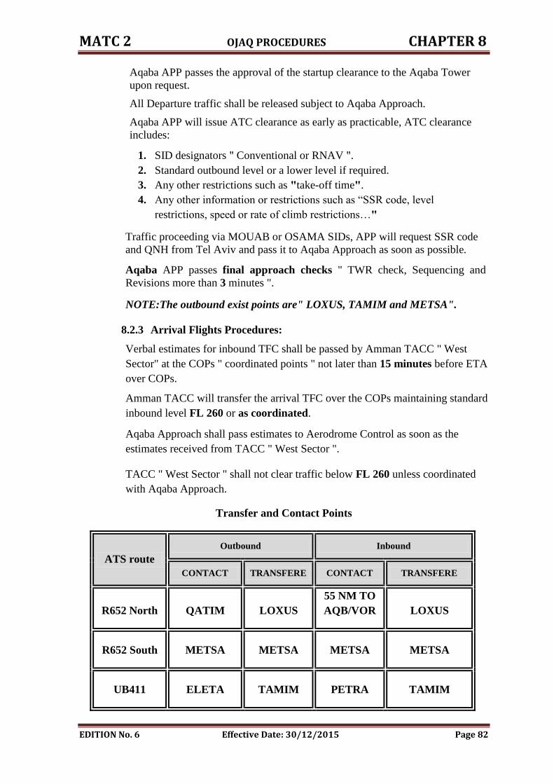
MATC 2 OJAQ PROCEDURES CHAPTER 8
EDITION No. 6 Effective Date: 30/12/2015 Page 82
Aqaba APP passes the approval of the startup clearance to the Aqaba Tower
upon request.
All Departure traffic shall be released subject to Aqaba Approach.
Aqaba APP will issue ATC clearance as early as practicable, ATC clearance
includes:
1. SID designators " Conventional or RNAV ".
2. Standard outbound level or a lower level if required.
3. Any other restrictions such as "take-off time".
4. Any other information or restrictions such as “SSR code, level
restrictions, speed or rate of climb restrictions…"
Traffic proceeding via MOUAB or OSAMA SIDs, APP will request SSR code
and QNH from Tel Aviv and pass it to Aqaba Approach as soon as possible.
Aqaba APP passes final approach checks " TWR check, Sequencing and
Revisions more than 3 minutes ".
NOTE:The outbound exist points are" LOXUS, TAMIM and METSA".
8.2.3 Arrival Flights Procedures:
Verbal estimates for inbound TFC shall be passed by Amman TACC " West
Sector" at the COPs " coordinated points " not later than 15 minutes before ETA
over COPs.
Amman TACC will transfer the arrival TFC over the COPs maintaining standard
inbound level FL 260 or as coordinated.
Aqaba Approach shall pass estimates to Aerodrome Control as soon as the
estimates received from TACC " West Sector ".
TACC " West Sector " shall not clear traffic below FL 260 unless coordinated
with Aqaba Approach.
Transfer and Contact Points
ATS route
Outbound Inbound
CONTACT TRANSFERE CONTACT TRANSFERE
R652 North QATIM LOXUS
55 NM TO
AQB/VOR LOXUS
R652 South METSA METSA METSA METSA
UB411 ELETA TAMIM PETRA TAMIM
MATC 2 OJAQ PROCEDURES CHAPTER 8
EDITION No. 6 Effective Date: 30/12/2015 Page 83
NOTE: The entry points " LOXUS , METSA and TAMIM "
Aqaba Approach will release inbound traffic to Tower when:
1. TACC " West Sector " shall release inbound traffic to Aqaba Approach at or
passing entry point vertically separated.
2. Aircraft carrying instrument Approach, when procedure turn completed.
3. In case Inbound Traffic is commencing a straight in visual Approach, it
shall be released to Aerodrome Control at 10 DME from AQB/DVOR.
4. In poor weather conditions traffic will not be released by Aqaba Approach
to Aerodrome Control until the pilot reports he has the runway insight.
5. Traffic carrying out visual Approach, Aqaba Approach shall release traffic
to to Aerodrome Control before entering CTR and passing 7000 FT.
Aqaba approach unit will give position check to tower when:
1. Passing AQB VOR outbound for aircraft commencing instrument approach
procedure ".
2. 15 DME AQB for aircraft coming straight in visual Approach.
NOTE: If traffic is required to hold for weather improvement, it will be held
in " BAKIR " hold.
8.2.4 Overflying Flights Procedures:
Overflying traffic entering Aqaba Approach at FL 250 or below shall contact
Aqaba Approach 10 minutes before METSA or QATIM and remain under their
control until passing the boundary of Aqaba Approach Control.
NOTE: Aqaba Approach airspace is classified as class "C" airspace.
8.2.5 RNAV Arrival Procedures:
APP should perform the following, beside the tasks that already agreed in the LoAs:
1. APP should pass the approach type to the TWR as soon as possible, not later
than IAF (BAKIR, LOXAL, QATIM).
2. Tower check is to be made prior the traffic leaves IAFs:
a) RWY01: LOXAL.
b) RWY19: QATIM.
3. APP will release the traffic to the TWR in these case:
a) RWY01: GENUN.
b) RWY19: NALBO.
4. Landing interval for successive inbound traffic for both RWYs is: 10NM.
8.2.6 Visual Approach:
Visual approach may only be approved when requested by the pilot provided that:
1. The aircraft is number one for Approach.
MATC 2 OJAQ PROCEDURES CHAPTER 8
EDITION No. 6 Effective Date: 30/12/2015 Page 84
2. The controller is satisfied that a visual Approach is acceptable in the
prevailing traffic and possible in prevailing weather.
3. Coordination is affected with TWR.
8.3 Landing Intervals:
Landing interval is 10 minutes for Medium and Heavy aircraft; succeeding
aircraft shall not be cleared for Approach unless preceding aircraft has passed
the Outer Marker.
NOTE: Caution should be exercised when light aircraft is commencing the
instrument Approach procedure, and then the landing interval shall be 16
minutes.
8.4 Runway Change:
1. Runway change will be initiated by King Hussein Tower.
2. Coordination will be effected with Approach.
3. Runway changes will take-effect immediately, if traffic situation permits.
4. ATC clearances for departure traffic should be revised.
NOTE:
1. Tailwind component shall not exceed 5 KTS. lCAO doe 4444.
2. When the crosswind component, including gusts, exceeds 28 km/h
(15 KTS), or the tailwind component, including gusts, exceeds 9 km/h (5KTS).
3. Tailwind shall not exceed more than 5 KTS, when nomination runway
in use, if the tailwind is more than 5 KTS and less than 10 KTS it should be
pilot request and his responsibilities to use runway other than runway in use,
if the traffic permits, when the tail wind is more than 10 KTS its forbidden
and the main RWY for operation is the one its QFU is against wind direction.
4. Crosswind component shall not exceed l0 KTS according to the table and
lCAO Doe 4444. With pilot approval.
8.5 Training , VFR and SVFR Flights:
8.5.1 General :
The VFR corridor has been established to be used by civil and military aircraft
proceeding to and from Aqaba/King Hussein aerodrome.
8.5.2 Lateral limits:
VFR corridor width is 3 NM.
8.5.3 Weather minima:
The corridor will be closed for routine operations if Aqaba weather is below
VFR minima or if reports indicate that weather along the route below VFR
minima.
MATC 2 OJAQ PROCEDURES CHAPTER 8
EDITION No. 6 Effective Date: 30/12/2015 Page 85
8.5.4 Responsibilities:
It is the direct responsibility of the pilot using this corridor to avoid collision
with other aircraft and to maintain VFR.
8.5.5 Operating rules:
Pilots are required to comply with the following operating rules:
1. Maintain VMC.
2. Maintain a continuous listening watch on the required ATC
frequency.
3. Make visual position reports at the mandatory reporting points.
4. Follow ATC instructions.
5. Advice ATC if unable to comply with ATC instructions.
8.5.6 Reporting points:
The following are visual mandatory reporting points:
RAS EN NAQB 295949N 0353024E.
RED SAND 295801N 0351252E.
EL-QUWEIRA 294811.45N 0351848.72E.
Terminal points:
BAKIR 293930N 0350530E.
QATIM 295600N 0351600E.
Traffic inbound and outbound from Aqaba/King Hussein aerodrome operating
VFR shall enter and leave Aqaba Approach Control Area via VFR corridors.
8.5.7 Arrival VFR route " V 4 " :
After QTR/VOR proceed to RAS-ENNAQAB then proceed to EL-QUWEIRA
hold descending to ALT 6500 FT to maintain by EL-QUWEIRA after
EL-QUWEIRA fly heading 280 DEG MAG then fly by ARABA highway to
final RWY 19 or join right hand down wind RWY 01.
All arrival VFR traffic flying on V4 should not leave EL-QUWEIRA holding
area unless instructed by Aqaba Approach.
In case of radio communication failure with the ARR VFR traffic on V4 route,
the aircraft should stick to the expected onward clearance and not to leave
EL-QUWEIRA before that time.
In case of arriving aircraft unable to get expected onward clearance or to
establish two way communication with Aqaba Approach the aircraft must return
to point of departure " Amman /Marka or Queen Alia Airport ".
Contact point for VFR traffic inbound to Aqaba/King Hussein via V4 route shall
be 5 Minutes before RAS ENNAQB.
MATC 2 OJAQ PROCEDURES CHAPTER 8
EDITION No. 6 Effective Date: 30/12/2015 Page 86
Release point for VFR inbound traffic to Aqaba/King Hussein shall be RAS EN
NAQB.
8.5.8 Departure VFR route " V3 ":
After departure proceed to RED SAND to cross RED SAND 6500 FT or above,
then continue to RAS ENNAQB and then to QTR VOR.
Contact point for VFR traffic departing Aqaba/King Hussein to the North via V3
is RED SAND.
Release point for VFR traffic departing Aqaba/King Hussein to the North via V3
is RAS ENNAQB.
8.5.9 VFR hold areas:
1. RAS ENNAQB Hold:
RAS ENNAQB position DME AQB DVOR 37 NM.
One minute inbound track 200 DEG MAG Right turn.
Minmum holding altitude for Ras en Naqb is altitude 7000 FT and
the maximum holding altitude 8500 FT.
2. EL QUWEIRA Hold:
EL QUWEIRA position 21 NM; DME AQB/DVOR.
One minute inbound track 235 DEG MAG. left turn.
EL QUWEIRA holding altitude is 6500 FT only.
3. BAKIR FIX Hold:
Radial 042 (AQB) VOR 07 DME One minute inbound track 222
DEG MAG. left turn at fix.
Minimum holding altitude 8000 FT.
Maximum holding level FL 180 " upper limit for Aqaba Approach
Area is 13000FT ALT" .
Emergency holding altitude 7000 FT.
8.5.10 Training areas:
1. North Training Area:
It is a training area established North of Aqaba Approach Control Area with the
following characteristics:
Name: Aqaba North Training Area
Purpose:
Training for light aircraft
Location:
North of Aqaba CTA
MATC 2 OJAQ PROCEDURES CHAPTER 8
EDITION No. 6 Effective Date: 30/12/2015 Page 87
Coordinates:
300004 N 351901E
300004 N 353301E
301504 N 353301E
301504 N 353001E
Lower Limits: 1000 FT AGL
Upper Limits: 6500 FT QNH
Remarks: Aqaba Approach Frequency is 119.2 MHZ.
All traffic leaving Aqaba control zone North bound proceeding to N.T.A must
obtain clearance before leaving the control zone from Aqaba Approach
" FREQ.119.2 MHZ ".
All traffic proceeding to N.T.A shall enter the area via " Red Sand reporting
point" to report establishing the area and operation normal every 15 minutes "
for alerting and RCF purposes".
All traffic intending to rejoin Aqaba control zone or to proceed back to Amman
after operating in the training area shall pass an estimate to Aqaba Approach for
rejoining or leaving the area proceeding to Amman.
NOTE: Rejoining time to Aqaba control zone shall be given immediately when
in contact with Aqaba Approach.
Rejoining Aqaba control zone from N.T.A:
All rejoining traffic shall leave N.T.A back to Aqaba via RAS EN NAQB then
via v4 route.
Radio communication failure procedures:
All traffic must establish two way radio contact with Aqaba approach control
before entering N.T.A.
Traffic experiencing loss of two- way radio contact shall proceed to Ras En
Naqb and carry out the failure rejoining procedure following V4 ARR.
Traffic experiencing radio failure during his operation in the training area shall
rejoin at Ras en Naqb on the previously given estimate and proceed to
El–Quweira and follow V4 route to Aqaba Airport and carry out radio failure
rejoining procedure.
2. J West Training Area:
It is a training area established South East of Aqaba Approach Control Area
with the following characteristics:
Name: J West Training Area
Purpose:
Training for light aircraft
MATC 2 OJAQ PROCEDURES CHAPTER 8
EDITION No. 6 Effective Date: 30/12/2015 Page 88
Location:
South East of Aqaba CTA
Coordinates:
291900 N 0360200E
Then along the highway to Ma'an
301100 N 0354300E
300700 N 0353500E
292500N 0353000E
Lower Limits: 500 FT AGL
Upper Limits: 6500 FT QNH
Remarks: Aqaba Approach Frequency is 119.2 MHZ.
All traffic leaving Aqaba control zone proceeding to J West must obtain
clearance before leaving the control zone from Aqaba Approach " FREQ.119.2
MHZ ".
All traffic proceeding to J West shall enter the area via " Red Sand reporting
point" to report establishing the area and operation normal every 15 minutes "
for alerting and RCF purposes".
All traffic intending to rejoin Aqaba control zone or to proceed back to Amman
after operating in the training area shall pass an estimate to Aqaba Approach for
rejoining or leaving the area proceeding to Amman.
Rejoining Aqaba control zone from N.T.A:
All rejoining traffic shall leave N.T.A back to Aqaba via RAS EN NAQB then
via v4 route.
Radio communication failure procedures:
All traffic must establish two way radio contact with Aqaba approach control
before entering N.T.A.
Traffic experiencing loss of two- way radio contact shall proceed to Ras En
Naqb and carry out the failure rejoining procedure following V4 ARR.
Traffic experiencing radio failure during his operation in the training area shall
rejoin at Ras en Naqb on the previously given estimate and proceed to
EL–QUWEIRA and follow V4 route to Aqaba Airport and carry out radio
failure rejoining procedure.
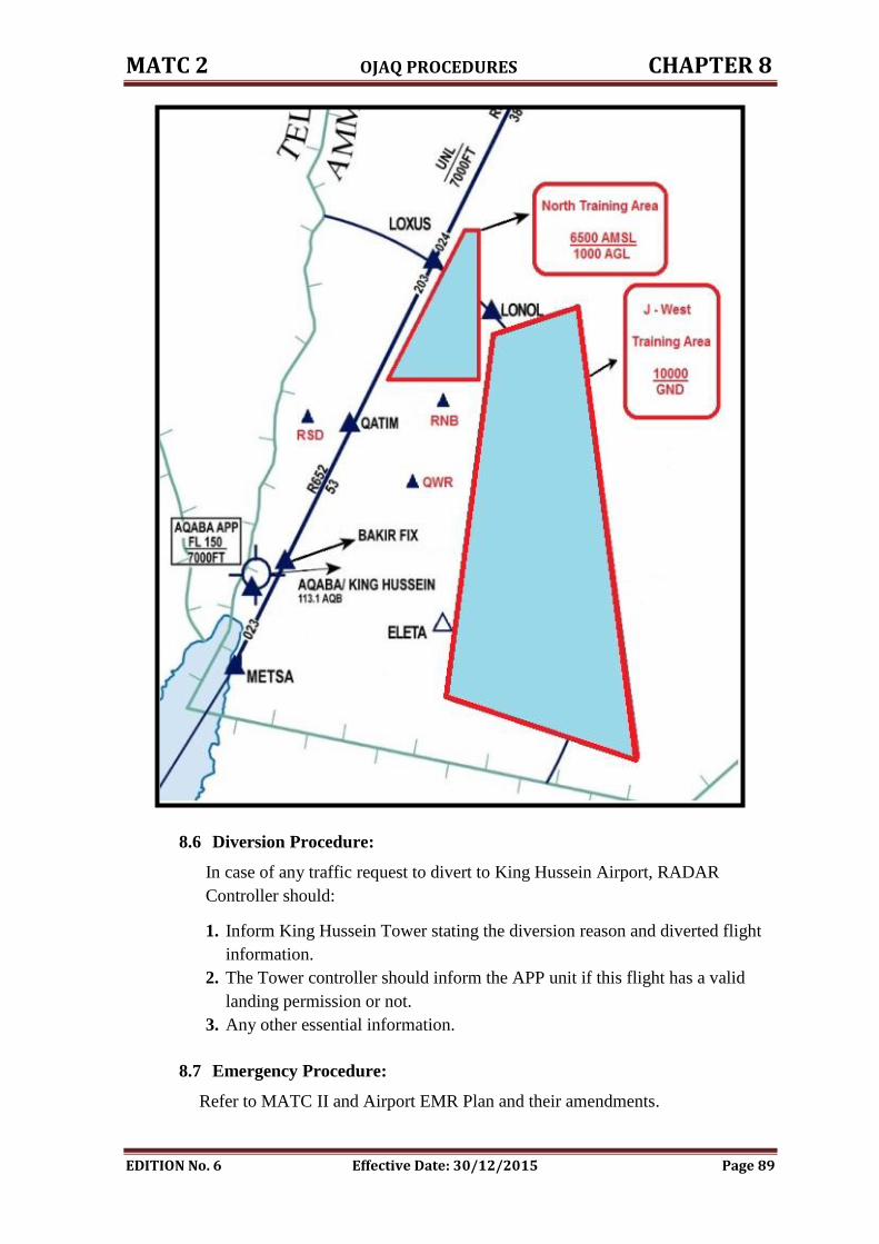
MATC 2 OJAQ PROCEDURES CHAPTER 8
EDITION No. 6 Effective Date: 30/12/2015 Page 89
8.6 Diversion Procedure:
In case of any traffic request to divert to King Hussein Airport, RADAR
Controller should:
1. Inform King Hussein Tower stating the diversion reason and diverted flight
information.
2. The Tower controller should inform the APP unit if this flight has a valid
landing permission or not.
3. Any other essential information.
8.7 Emergency Procedure:
Refer to MATC II and Airport EMR Plan and their amendments.
MATC 2 OJAQ PROCEDURES CHAPTER 8
EDITION No. 6 Effective Date: 30/12/2015 Page 90
The incident report shall be filled by the unit in which the incident took place in
its area of responsibility.
TACC supervisor shall inform DANS; DANS will inform the concerned at
Safety departments " Investigation, Airworthiness, and Aircraft Operation "
accordingly.
Tower supervisor shall inform TACC about the following cases:
1. Local standby.
2. Full emergency.
3. Aircraft accident.
4. Weather standby.
5. Hi-jacking or bomb threat.
6. Strayed aircraft, overdue position report.
The message will contain the following details:
1. Type of the case.
2. Aircraft call sign and type.
3. Nature of flight " DEP , ARR , Circuit …….etc ".
4. ETA " for local traffic ".
5. Time of accident.
6. Position of accident.
7. When normal operation is resumed.
8.8 Fuel Dumping:
This procedure for any inbound or outbound traffic, the ATC should implement
the following:
1. Fuel Dumping will be carried out in BAKIR hold.
2. Fuel Dumping Operation shall be carried out at least 2000 FT above terrain.
3. Vertical separation at least 2000 FT below and 1000 FT above the aircraft
dumping fuel.
4. ATC shall pass all necessary instructions prior to the commencement of Fuel
Dumping Operation " no contact with the flight during fuel dumping ".
5. TWR ATC shall inform Amman TACC and ADOC.
6. The pilot should report the duration of the fuel dumping.
8.9 Miscellaneous Operations:
The following information shall immediately be coordinated between Aqaba
Approach and AMMAN Approach Unit:
1. Missed approach.
2. Diversion.
3. Closure of the airport.
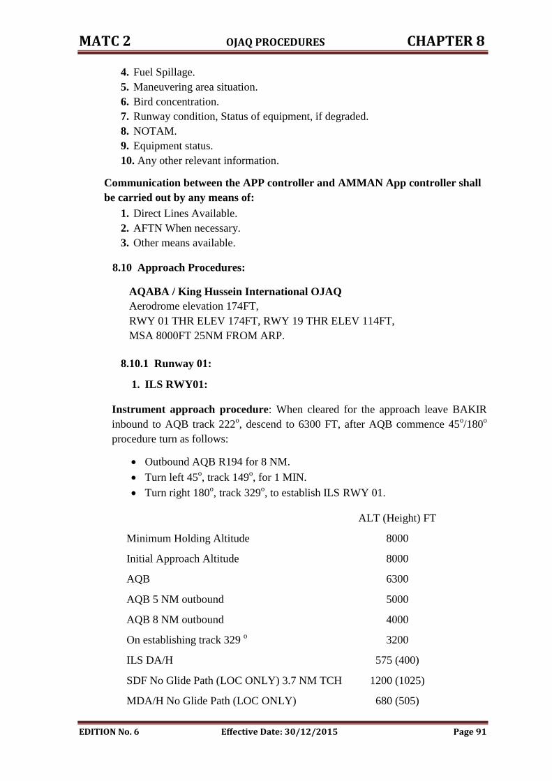
MATC 2 OJAQ PROCEDURES CHAPTER 8
EDITION No. 6 Effective Date: 30/12/2015 Page 91
4. Fuel Spillage.
5. Maneuvering area situation.
6. Bird concentration.
7. Runway condition, Status of equipment, if degraded.
8. NOTAM.
9. Equipment status.
10. Any other relevant information.
Communication between the APP controller and AMMAN App controller shall
be carried out by any means of:
1. Direct Lines Available.
2. AFTN When necessary.
3. Other means available.
8.10 Approach Procedures:
AQABA / King Hussein International OJAQ
Aerodrome elevation 174FT,
RWY 01 THR ELEV 174FT, RWY 19 THR ELEV 114FT,
MSA 8000FT 25NM FROM ARP.
8.10.1 Runway 01:
1. ILS RWY01:
Instrument approach procedure: When cleared for the approach leave BAKIR
inbound to AQB track 222o, descend to 6300 FT, after AQB commence 45
o/180
o
procedure turn as follows:
Outbound AQB R194 for 8 NM.
Turn left 45o, track 149
o, for 1 MIN.
Turn right 180o, track 329
o, to establish ILS RWY 01.
ALT (Height) FT
Minimum Holding Altitude 8000
Initial Approach Altitude 8000
AQB 6300
AQB 5 NM outbound 5000
AQB 8 NM outbound 4000
On establishing track 329 o 3200
ILS DA/H 575 (400)
SDF No Glide Path (LOC ONLY) 3.7 NM TCH 1200 (1025)
MDA/H No Glide Path (LOC ONLY) 680 (505)
MATC 2 OJAQ PROCEDURES CHAPTER 8
EDITION No. 6 Effective Date: 30/12/2015 Page 92
NOTE:
1. Remain within Jordanian FIR all the time.
2. While in the procedure turn DO NOT EXCEED 13NM AQB to the south.
3. While turning inbound remain within AQB R206.
Max IAS 180Kts.
2. Missed Approach Procedure RWY 01:
When initiating missed approach, fly on R014o AQB climb to 8000FT, after
passing 6300FT turn right to enter BAKIR hold, contact ATC for further
instructions.

CHAPTER NINE
FAILURES
MATC 2 Failures CHAPTER 9
EDITION No. 6 Effective Date: 30/12/2015 Page 93
9. FAILURES:
Supervisor must record any failure in the Log Book.
9.1 Partial Service Failure:
9.1.1 INDRA or THALES RADAR Technical Failure:
TACC Supervisor shall:
1. Advice RADAR maintenance section.
2. Advice TACC Chief and DANS.
3. Advice control towers.
4. Take any necessary actions to ensure RADAR service provided up to
standard.
9.1.2 System Data Integrity:
TACC Supervisor shall advice all ATC in duty to increase lateral and vertical
separation and if necessary to use procedural separation.
9.2 Complete RADAR Technical Failure:
TACC Supervisor shall:
1. Stop all departures and will be released subject to traffic situation.
2. Advice RADAR maintenance section and try to determine the duration time of
failure if it is possible.
3. Advice TACC Chief, DANS and ADOC.
4. Advice control towers.
5. Advice adjacent control units.
6. Apply non-RADAR emergency procedures in accordance to MATC I or apply
500 FT and 10 minutes separation when required.
7. Check THALES center in order to establish TACC operation on it if
applicable.
8. Broadcast through ATIS regarding the RADAR service within AMMAN FIR.
9. Issue NOTAM if necessary.
9.3 VHF Communication System Failure:
In case of failure one "or more" of the VHF frequencies "128.3 MHz or 128.5 MHz
or 128.9 MHz" in Amman TACC, TACC Supervisor shall follow the following
instructions:
1. Advice communication maintenance section and try to determine the
duration time of failure if it is possible.
2. Advice TACC Chief and DANS.
3. Advice control towers.
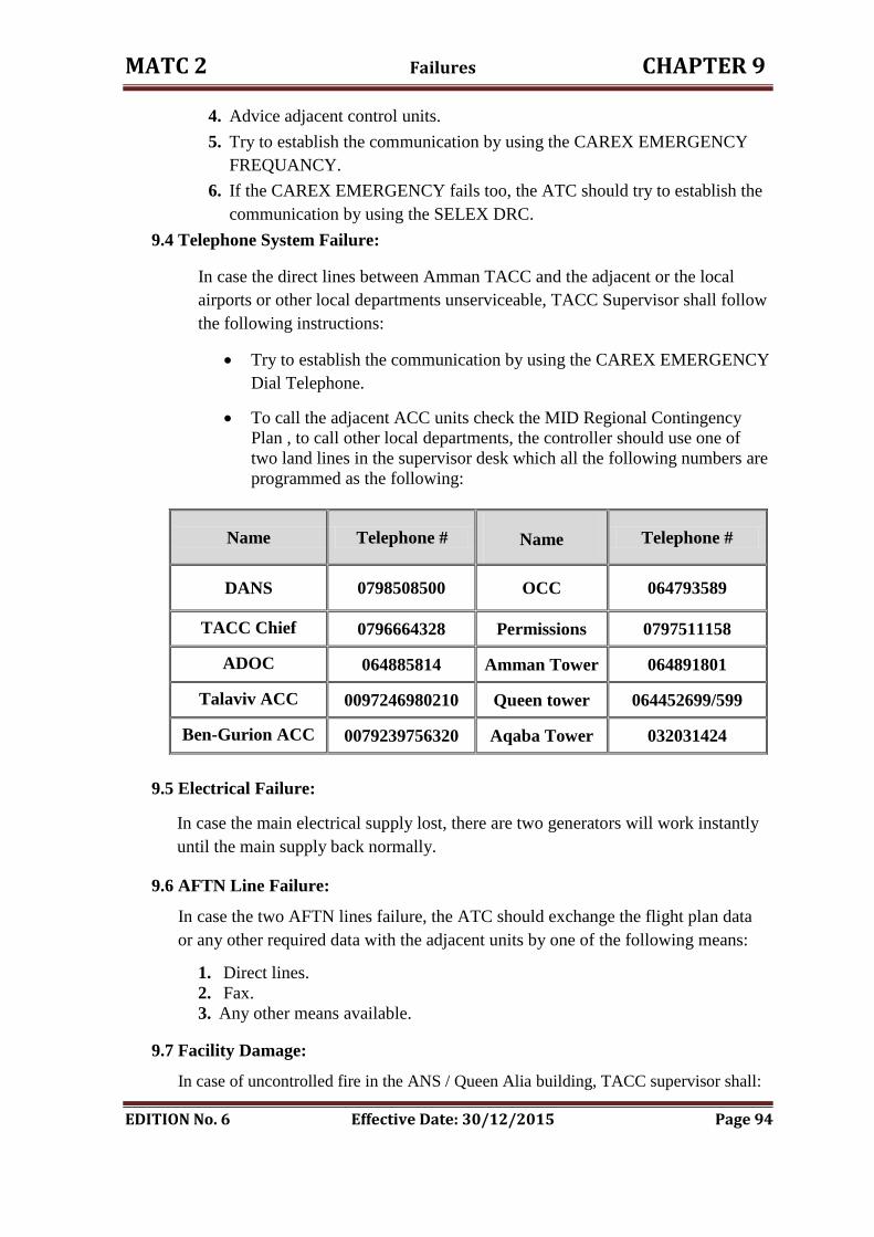
MATC 2 Failures CHAPTER 9
EDITION No. 6 Effective Date: 30/12/2015 Page 94
4. Advice adjacent control units.
5. Try to establish the communication by using the CAREX EMERGENCY
FREQUANCY.
6. If the CAREX EMERGENCY fails too, the ATC should try to establish the
communication by using the SELEX DRC.
9.4 Telephone System Failure:
In case the direct lines between Amman TACC and the adjacent or the local
airports or other local departments unserviceable, TACC Supervisor shall follow
the following instructions:
Try to establish the communication by using the CAREX EMERGENCY
Dial Telephone.
To call the adjacent ACC units check the MID Regional Contingency
Plan , to call other local departments, the controller should use one of
two land lines in the supervisor desk which all the following numbers are
programmed as the following:
Name Telephone # Name Telephone #
DANS 0798508500 OCC
064793589
TACC Chief 0796664328 Permissions 0797511158
ADOC 064885814 Amman Tower 064891801
Talaviv ACC 0097246980210 Queen tower 064452699/599
Ben-Gurion ACC 0079239756320 Aqaba Tower 032031424
9.5 Electrical Failure:
In case the main electrical supply lost, there are two generators will work instantly
until the main supply back normally.
9.6 AFTN Line Failure:
In case the two AFTN lines failure, the ATC should exchange the flight plan data
or any other required data with the adjacent units by one of the following means:
1. Direct lines.
2. Fax.
3. Any other means available.
9.7 Facility Damage:
In case of uncontrolled fire in the ANS / Queen Alia building, TACC supervisor shall:
MATC 2 Failures CHAPTER 9
EDITION No. 6 Effective Date: 30/12/2015 Page 95
1. Ensure that the fire extinguisher system is activated.
2. Advice the Queen Tower.
3. Advice the civil defense either by telephone or through the tower or any other
means.
4. Initiate MID Regional contingency plan if required.
In case part of INDRA Center building destroyed initiate TACC operation in
THALES Center, if not applicable initiate MID Regional contingency plan.
In case major destruction of the building initiate MID Regional contingency plan
and the evacuation plan.
The following evacuation NOTAMs should issue as follow:
“Due to emergency evacuation of Amman TACC all ATC services are
terminated. Flights within Amman FIR should continue as cleared and
contact the next ATC agency as soon as possible.
Flights not in receipt of an ATC clearance should land at an appropriate
airfield or request clearance to avoid Amman FIR. Flights should monitor
frequency 128.3 MHz”
Broadcast an evacuation message on appropriate frequencies:
“Emergency evacuation of Amman TACC is in progress. No air traffic
control service will be provided by Amman TACC. Use extreme caution
and monitor frequency 128.3 MHz, emergency frequencies and air to air
frequencies. Contact the next air traffic control unit as soon as possible”.

CHAPTER TEN
ROYAL FLIGHTS
MATC 2 ROYAL FLIGHTS CHAPTER 10
EDITION No. 6 Effective Date: 30/12/2015 Page 96
10. ROYAL FLIGHTS
Royal Flight Definition ( VVIP Flight ):
The Royal flight the movement of an aircraft specifically tasked to carry one or more
members of The Royal Family afforded such status by the Head of Royal Travel, the
Royal Household .
The term ( VVIP Flight ) refers to the flights of the following persons:
1. His Majesty the King; HMK.
2. Her Majesty the Queen; HMQ.
3. Heads of Foreign Government or states.
4. As coordinated by Royal Flight ( RF ) operations.
VIP Flights within Jordan airspace by members of other Royal Families, Prime
Ministers and Heads of States of foreign countries, may also be afforded Royal Flight
status by the air traffic service units, when notified by the Royal Flight Operation .
The term ( VIP Flight ) refers to the flights of the following persons:
1. The Royal Family;
2. Distinguished guests.
10.1 General:
10.1.1 Royal Flights have priority over all other flights except those in emergency,
standard separation will be used in cruising flight, a minimum of 2000 FT
separation will be used in the climb and descent phase.
10.1.2 When advising other traffic of delay or non standard procedure, due to Royal
Flights the following phraseology will be used, ".....Due to Special
Movement".
All R/T should be confined to essential control messages with standard
phraseology.
Royal Flights may operate on VHF or UHF and will always monitor the
alternate channel.
10.1.3 Royal Flights shall be controlled by the supervisor and/or the most senior
controller, the flight will remain on one frequency until establish contact with
the tower frequency at the intended aerodrome of landing.
10.1.4 Supervisor will inform immediately the DANS about any Royal Flight as
follows:
1. During morning shift via the chief of TACC.
2. During the afternoon, night shift and holidays by the TACC supervisor.
MATC 2 ROYAL FLIGHTS CHAPTER 10
EDITION No. 6 Effective Date: 30/12/2015 Page 97
10.2 Aerodrome Procedures:
10.2.1 The Royal Squadron is responsible for specifying the exact departure time and
approximate arrival times to the RJAF Liaison Officer. The RJAFLO will pass
the times to the Tower Supervisor of the Aerodrome of Departure and the
TACC.
10.2.2 The Tower Supervisor at the concerned unit will advise the Chief ATC of the
ETD.
10.2.3 The TACC is responsible for advising the arrival aerodrome of the Royal
Flight ETA as soon as possible.
10.2.4 The Tower Supervisor will advise the Chief ATC and the RJAFLO of the
Royal Flight ETA.
10.2.5 When taking over watch the Tower Supervisor will advise the TACC Shift
Supervisor of all ATAs and ATDs of the Royal Flights.
10.2.6 The Tower Supervisor will ensure that the runway and taxiways are inspected
before -arrival or departure of royal flight.
10.2.7 Any flight requiring special handling associated with the Royal Flight will be
notified by the Royal Squadron in accordance with 10.2.1 and given normal
Departure Clearance before or after the Royal Flight, as specified.
10.2.8 The Tower has one runway available for VVIP / VIP arrivals and departures,
ATC will give clearance for the runway to be used based on wind velocity and
traffic condition.
10.2.9 Variable direction circuits may be used at times in accordance with ATC
instructions in the interest of noise abatement producer.
10.2.10 At queen alia airport when there are two runways are available, runway 26 L
will be designated for VVIP / VIP operations.
10.2.11 For arrival VVIP Flights, all movements will be stopped 15 minutes before
the Royal Flight ETA / ATA till door open time.
10.2.12 For departure VVIP Flights, all movements will be stopped from door close
time or starting up till 5 minutes after takeoff.
10.2.13 No VFR flights shall be allowed during the period of the VVIP Flights is
expected to operate in controller airspace.
NOTE: The ATM headquarter may adjust the above timings to ensure that
there is no disturbance during the period of ceremonies at the airport and if
required they may close the airfield to other operations.
The tower shall inform TACC about VIP movement:
Nature of flight.
Aircraft call sign, type and if section number aircraft.
Destinations.
If applied closer time and expected period.
When normal operation is resumed.
MATC 2 ROYAL FLIGHTS CHAPTER 10
EDITION No. 6 Effective Date: 30/12/2015 Page 98
10.3 Approach Control Procedures:
10.3.1 If it is known that the departure route of the Royal Flight will not be conflict
with the STARs arrival to other than the departure aerodrome will be held
either as 10.3.2 or at AMN or QTR so as not to conflict with the Royal
Departure.
10.3.2 If inbound aircraft conflict with the departing Royal Flight, they will be routed
to QAA and held at FL 200 and above, from 15 minutes before until 15
minutes after the Royal Flight ETD or ATD " ARR ACFT ATA QAA " or
until the conflict is resolved.
10.3.3 For inbound Royal Flight:
1. An EAT should be calculated using 10 minutes between the preceding aircraft
and the Royal Flight.
2. Any aircraft causing delay will be rerouted or held to ensure no delay to the
Royal Flight.
3. The pilot of the aircraft will be informed before start-up about this action. If the
aircraft held on ground, the take-off clearance will be calculated according to:
a) Along airway A412, if the Royal Flight and the opposite aircraft will meet
at or after the point 80 NM QAA, the aircraft held on ground, will be
cleared for take-off. If they will meet before the point 80 NM QAA, the
aircraft will be either held on ground or re-routed.
b) Along airway R652 to GRY, if the intersection point will be GRY or after,
the aircraft will be released for take-off, if they will intersect before GRY,
follow the same action in the point " a " above.
c) Along airway R652 to AQABA, the point is 60 NM or more south of QTR.
10.3.4 Approach unit will issue EATs to Area Unit based on 10.3.1 / 2 and 10.3.3.
10.4 Area Control Procedures:
10.4.1 All inbound to TMA Airports will be cleared to QAA hold at FL 200 and
above with EATs as given by Approach Unit when a Royal Flight is outbound
from a TMA Airport.
10.4.2 When a Royal Flight is inbound to a TMA Airport all inbound flights will be
cleared to the normal holding fix or rerouted and held as specified by Approach
Unit.
10.4.3 When a Royal Flight is outbound from AQABA, inbound flights will be held at
FL 180 in BAKIR hold from 15 minutes before to 15 minutes after the Royal
Flight ETD / ATD.
MATC 2 ROYAL FLIGHTS CHAPTER 10
EDITION No. 6 Effective Date: 30/12/2015 Page 99
10.4.4 When a Royal Flight is inbound to AQABA inbound flights will be held at
FL180 in BAKIR hold to avoid delay to the Royal Flight. The next inbound
EAT will be based on the landing time of the Royal Flight plus 15 minutes.
10.4.5 When a Royal Flight is departing a TMA Airport and routing onto or overhead
AQABA, the following rules will apply:
1. AQABA departures via QTR will be stopped 15 minutes before Royal
Flight ETD until ATD; departures may then be released using 2000 FT
vertical separation below the Royal Flight when coordinated with ADOC.
2. AQABA departure will cease in accordance with 10.2.8.
3. For Royal Flights via METSA, AQABA departures via NWB will be
stopped 15 minutes before until 15 minutes after the Royal Flight over
flight ETA/ATA METSA unless coordinated with ADOC.
10.4.6 The TACC Shift Supervisor will pass all ATAs / ATDs with next position
estimates and position reports to the ADOC. During working hours the TACC
Shift Supervisor will notify DANS and after working hours, he will notify the
Chief Commissioner.
10.5 VIP Flights:
10.5.1 VIP Flights may be designated for any flight carrying members of the Royal
Family or Government Officials.
10.5.2 VIP Flights will not be afforded Royal Flight Status but will if traffic permits
be afforded expeditious handling.
10.5.3 Information on VIP Flights will be provided to ADOC, RJAFLO and RJAF
Operations on request.
Tower Shift Supervisor will advise Chief ATC of the ETA / ETD of any VIP
Flight during normal working hours.
10.5.4 Tower Shift Supervisor will coordinate with Ground Operations and RJAF
Operations regarding parking area for inbound VIP Flights.
10.6 Royal Training and Helicopter Flights:
10.6.1 The following procedures will be applied for all circuit training flights of H.M.
KING ABDULLAH THE SECOND and when requested by the Royal
Squadron for other members of the Royal Family.
MATC 2 ROYAL FLIGHTS CHAPTER 10
EDITION No. 6 Effective Date: 30/12/2015 Page 100
10.6.2 The Royal Squadron will advise the RJAFLO of all Royal Training Flights.
The RJAFLO will advise the Tower Shift Supervisor of training details
affecting the aerodrome circuit.
10.6.3 All other circuit flying will be stopped for the duration of the Royal Training
Flight.
10.6.4 The Royal Training aircraft will be advised of the ETA / ETD of any IFR
flight during the training period that will affect the Royal Training.
Coordination will be effected with the Royal Training Flight to avoid delay to
IFR Flights.
10.6.5 Royal Helicopter Flights within Control Zones will be given priority and
separation from other flights and Royal Flight Standby will be implemented
while the flight is within the CTR.
Royal Helicopter Flights outside CTR are the responsibility of the ADOC.
10.7 VIP Training and Helicopter Flights:
VIP Helicopter routes for flights inbound and outbound aerodrome Control Zone as
follows:
1. Are identified alphabetically using geographical separation not less than 5
minutes apart
2. Minimum vertical separation of 1000 Feet and are instructed by ATC
controllers.
3. ATC clearance for the runways to be used based on wind velocity and traffic
condition.
10.8 ESCORT Flights:
The ADOC and the commander of the ESCORT Flight shall have coordination of
final authority for conduction flight in and out of the controlled air space, Airways and
Control zone as necessary to fulfill the coordination ESCORT needed.
10.9 Take over Watch ( TOW ) to handle VVIP / VIP flight:
Prior to taking over watch or an operating position, ATC must:
1. Ensure that she/he has a full understanding of the air traffic situation
including an awareness of clearances issued but not yet acted upon and any
developing situation requiring early attention;
2. Familiarize himself with the serviceability of all equipment under her/his
charge and responsible to be used during VIP flight keeping (e.g. radio,
approach aids, telephone lines and aerodrome lighting);
3. Obtain all relevant information and be familiarized with the meteorological
condition and trends for the period of VIP flight and where practicable get
MATC 2 ROYAL FLIGHTS CHAPTER 10
EDITION No. 6 Effective Date: 30/12/2015 Page 101
a personal briefing from a meteorological office;
4. Ensure she/he is fully conversant with the latest promulgated orders,
instructions, notices and information, particularly with reference to the
serviceability of aerodromes and other air navigation facilities;
5. .Note should be taken of details regarding any presidential, VVIP or other
special flights expected during the period of watch.
6. Inspect the airfield (including runways and taxiways) for maintenance for the
use of VVIP flight.
7. Delay of other flight will be notified every 10 minutes by unit concerned.

CHAPTER ELAVEEN
REDUCED VERTICAL SEPARATION MINIMA
MATC 2 RVSM CHAPTER 11
EDITION No. 6 Effective Date: 30/12/2015 Page 102
11. REDUCED VERTICAL SEPARATION MINIMA
1111..11 The Benefits of RVSM::
1. Decrease en route delays.
2. Increase flight profiles.
3. Reduces en route congestion by adding six new flight levels.
4. Provides more flexibility to the ATC controllers; reduces workload, less
RADAR Vectoring.
5. More effective and increased options for re-routing flights e.g. " around
weather " .
6. Increased ATM efficiency.
7. Reduce fuel burn consequently fuel saving of approximately 1%P/H "per
hour".
11.2 RVSM Implementation Needs:
1. Increase airspace capacity.
2. Obtain more operational flexibility.
3. To reduce traffic congestion.
11.3 RVSM Flight Levels:
1. FL 280 and below are Non RVSM Flight Levels.
2. 001º-179º FL " 290- 310-330-350-370-390-410 " is RVSM Eastbound levels.
3. 180º-360º FL " 300-320-340-360-380-400 " are RVSM Westbound levels.
4. FL 430 and above are Non RVSM Flight Levels.
11.4 Flight in RVSM Airspace:
In summary, the rules for flight in RVSM airspace are that ATC shall:
1. Provide a 1000 FT vertical separation minimum between RVSM Compliant
aircraft.
2. Provide a 2000 FT vertical separation minimum between Non-RVSM
Compliant aircraft and any other aircraft.
3. Provide 2000 FT vertical separation minimum between all formation flights of
civil or State aircraft from any other aircraft.
11.5 RVSM Flight Planning Requirements:
1. Flight Priority:
I. It should be noted that RVSM Compliant aircraft will be given priority for
level allocation over Non-RVSM Compliant aircraft.
II. Specific Flight Planning procedures have been developed for RVSM flights.
These are included in ICAO Doc 7030/4, MID Regional Supplementary
Procedures.
MATC 2 RVSM CHAPTER 11
EDITION No. 6 Effective Date: 30/12/2015 Page 103
2. The flight plan " FPL" shall include:
I. Operators of RVSM Compliant aircraft shall insert " W " in item " 10 a " of
the FPL Regardless of requested Flight Level.
II. Operators of Non-RVSM Compliant State aircraft with a RFL of 290 or
above shall insert " STS/NONRVSM " in item 18 of the FPL.
III. Operators of formation flights of RVSM-Compliant State aircraft shall NOT
Insert " W " in item " 10 a " of the FPL.
IV. Operators filing Repetitive Flight Plans " RPLs " shall include in item Q of
the RPL the RVSM Compliant status " EQPT/W " for RVSM Compliant
aircraft, and " EQPT/ " for Non-RVSM Compliant aircraft.
V. If a change of aircraft on an RPL results in a modification of the RVSM
Compliant status in item Q, the operators shall submit a change Message
" CHG ".
11.6 RVSM Airborne Systems Requirement:
11.6.1 The following systems must be fully operational prior to entering RVSM
airspace:
1. Two altitude measurement systems.
2. Automatic altitude keeping device.
3. At least one altitude-reporting transponder.
4. One altitude alerting system.
NOTE: Should any of the required equipment fail prior to entering RVSM airspace,
the pilot should request a new clearance to avoid flight in this airspace.
11.6.2 Transponder Requirements:
1. An operating Mode C transponder is required for flight in all airspace in the
Amman FIR airspace.
2. The tolerance value used to determine that pressure-altitude-derived level
information displayed to the controller is accurate shall be ±60 m "±200 ft "in
RVSM airspace.
In other airspace, it shall be ±90 m " ±300 ft ", except that the appropriate
ATS authority may specify a smaller criterion, but not less than ± 60 m
" ±200 ft ", if this is found to be more practical. Geometric height information
shall not be used for separation.
3. After confirmation of the aircraft’s level, Mode C readout continues to differ
from the cleared flight level by 60 m " 200 FT " or more, ATC will follow
the existing ICAO procedures prescribed for the failure of Mode C in flight or
as prescribed in Chapter 4.
MATC 2 RVSM CHAPTER 11
EDITION No. 6 Effective Date: 30/12/2015 Page 104
11.7 System Support:
The requirement for ATC to provide two different VSM in the same RVSM
airspace 1000 FT and 2000 FT VSM generates safety critical system support
requirements:
1. Radar display systems, if available, must provide controllers with continuous
and unambiguous information on the RVSM compliant status of all flights
under their responsibility.
2. Flight strips must display for controllers the Non-RVSM compliant status of all
civil and State aircraft.
3. Where applicable, the indication that a Non-RVSM compliant aircraft is a State
aircraft should be displayed, both on the radar display and on the flight Strip.
4. Automatic conflict alert systems modified to use the RVSM compliant or Non-
RVSM Compliant status of the aircraft and apply the appropriate VSM of 1000
FT or 2000 FT alerting trigger.
11.8 Contingency Procedures:
If an RVSM compliant aircraft cannot comply with RVSM height-keeping
requirements because of equipment failure, weather, turbulence, etc, ATC will
provide a 2000 FT VSM or an appropriate horizontal separation from all other
aircraft. Normally, such aircraft should be cleared out of RVSM Airspace,
" FL 280- or FL 430+ ".
11.8.1 Meteorological Coordination:
Close coordination between ATS and MET is very important, especially in RVSM
airspace, to get early information on severe weather activity and clear air
turbulence " CAT " for areas where it may affect the safe operation of RVSM
flights.
11.8.2 Height keeping errors:
There are two categories of Errors:
1. Technical Errors, or Altimetry System Errors " ASE ", caused by
inaccuracies in the height-keeping equipment of aircraft.
2. Operational Errors, or Assigned Altitude Deviation " AAD ", caused by
mistakes, by ATC or Flight Crews, which result in aircraft being flown at
incorrect flight levels.
ASE and AAD are the main components of Total Vertical Error " TVE "
the target level of Safety " TLS " must count for the risk analysis from
both technical and operational errors.
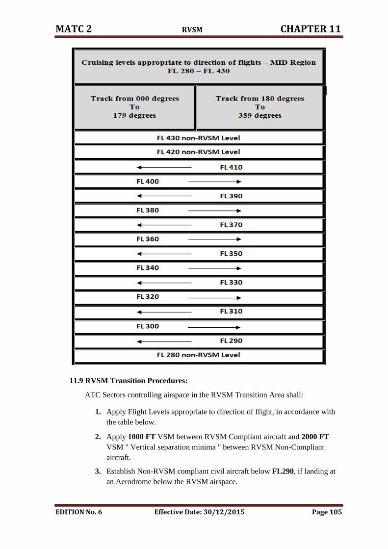
MATC 2 RVSM CHAPTER 11
EDITION No. 6 Effective Date: 30/12/2015 Page 105
11.9 RVSM Transition Procedures:
ATC Sectors controlling airspace in the RVSM Transition Area shall:
1. Apply Flight Levels appropriate to direction of flight, in accordance with
the table below.
2. Apply 1000 FT VSM between RVSM Compliant aircraft and 2000 FT
VSM " Vertical separation minima " between RVSM Non-Compliant
aircraft.
3. Establish Non-RVSM compliant civil aircraft below FL290, if landing at
an Aerodrome below the RVSM airspace.
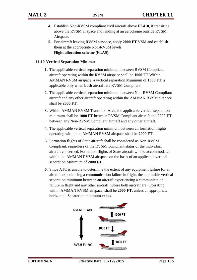
MATC 2 RVSM CHAPTER 11
EDITION No. 6 Effective Date: 30/12/2015 Page 106
4. Establish Non-RVSM compliant civil aircraft above FL410, if transiting
above the RVSM airspace and landing at an aerodrome outside RVSM
Airspace.
5. For aircraft leaving RVSM airspace, apply 2000 FT VSM and establish
them at the appropriate Non-RVSM levels.
Flight allocation scheme (FLAS).
11.10 Vertical Separation Minima:
1. The applicable vertical separation minimum between RVSM Compliant
aircraft operating within the RVSM airspace shall be 1000 FT Within
AMMAN RVSM airspace, a vertical separation Minimum of 1000 FT is
applicable only when both aircraft are RVSM Compliant.
2. The applicable vertical separation minimum between Non-RVSM Compliant
aircraft and any other aircraft operating within the AMMAN RVSM airspace
shall be 2000 FT.
3. Within AMMAN RVSM Transition Area, the applicable vertical separation
minimum shall be 1000 FT between RVSM Compliant aircraft and 2000 FT
between any Non-RVSM Compliant aircraft and any other aircraft.
4. The applicable vertical separation minimum between all formation flights
operating within the AMMAN RVSM airspace shall be 2000 FT.
5. Formation flights of State aircraft shall be considered as Non-RVSM
Compliant, regardless of the RVSM Compliant status of the individual
aircraft concerned. Formation flights of State aircraft will be accommodated
within the AMMAN RVSM airspace on the basis of an applicable vertical
separation Minimum of 2000 FT.
6. Since ATC is unable to determine the extent of any equipment failure for an
aircraft experiencing a communication failure in flight, the applicable vertical
separation minimum between an aircraft experiencing a communication
failure in flight and any other aircraft, where both aircraft are Operating
within AMMAN RVSM airspace, shall be 2000 FT, unless an appropriate
horizontal Separation minimum exists.
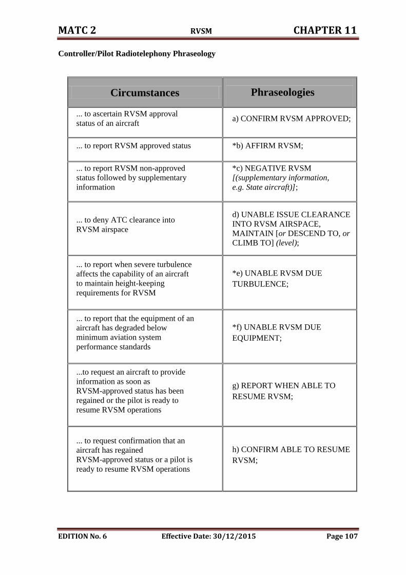
MATC 2 RVSM CHAPTER 11
EDITION No. 6 Effective Date: 30/12/2015 Page 107
Controller/Pilot Radiotelephony Phraseology
Circumstances
Phraseologies
... to ascertain RVSM approval
status of an aircraft a) CONFIRM RVSM APPROVED;
... to report RVSM approved status *b) AFFIRM RVSM;
... to report RVSM non-approved
status followed by supplementary
information
*c) NEGATIVE RVSM
[(supplementary information,
e.g. State aircraft)];
... to deny ATC clearance into
RVSM airspace
d) UNABLE ISSUE CLEARANCE
INTO RVSM AIRSPACE,
MAINTAIN [or DESCEND TO, or
CLIMB TO] (level);
... to report when severe turbulence
affects the capability of an aircraft
to maintain height-keeping
requirements for RVSM
*e) UNABLE RVSM DUE
TURBULENCE;
... to report that the equipment of an
aircraft has degraded below
minimum aviation system
performance standards
*f) UNABLE RVSM DUE
EQUIPMENT;
...to request an aircraft to provide
information as soon as
RVSM-approved status has been
regained or the pilot is ready to
resume RVSM operations
g) REPORT WHEN ABLE TO
RESUME RVSM;
... to request confirmation that an
aircraft has regained
RVSM-approved status or a pilot is
ready to resume RVSM operations
h) CONFIRM ABLE TO RESUME
RVSM;
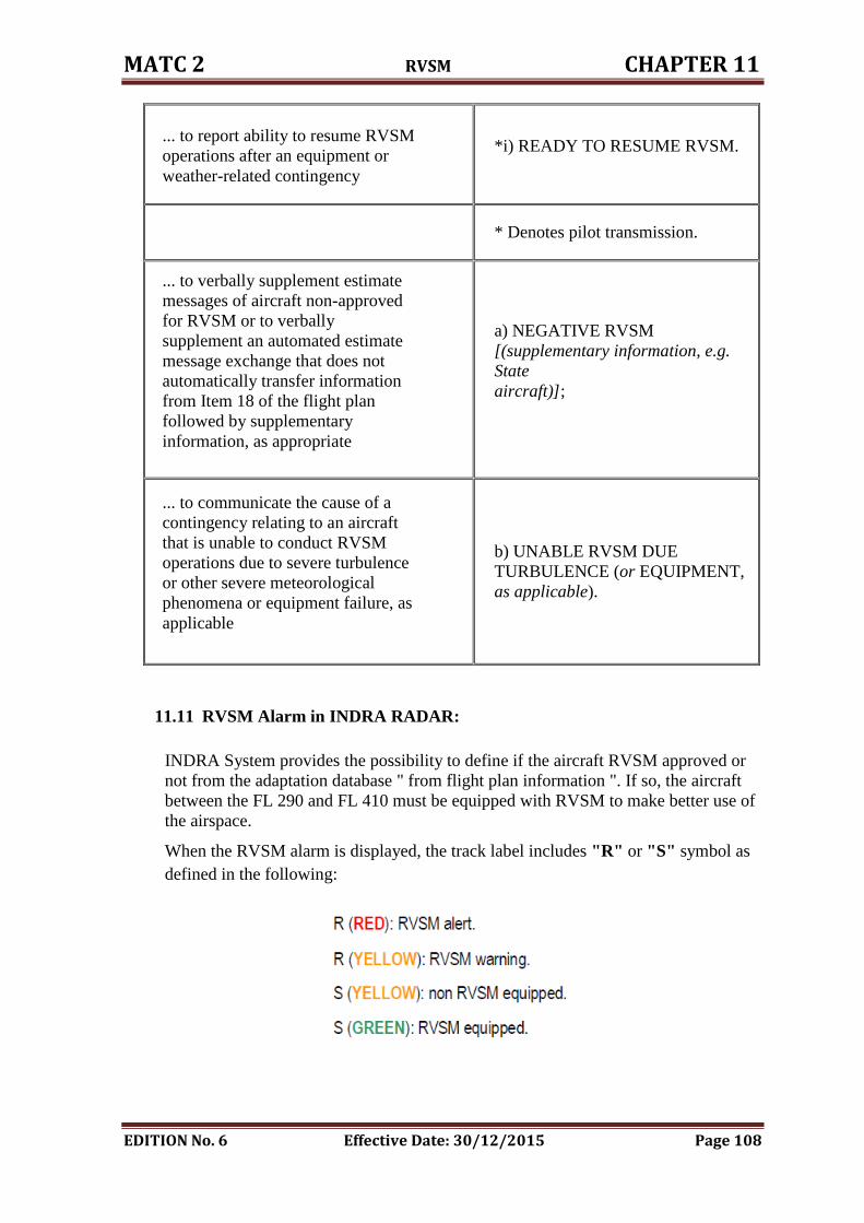
MATC 2 RVSM CHAPTER 11
EDITION No. 6 Effective Date: 30/12/2015 Page 108
... to report ability to resume RVSM
operations after an equipment or
weather-related contingency
*i) READY TO RESUME RVSM.
* Denotes pilot transmission.
... to verbally supplement estimate
messages of aircraft non-approved
for RVSM or to verbally
supplement an automated estimate
message exchange that does not
automatically transfer information
from Item 18 of the flight plan
followed by supplementary
information, as appropriate
a) NEGATIVE RVSM
[(supplementary information, e.g.
State
aircraft)];
... to communicate the cause of a
contingency relating to an aircraft
that is unable to conduct RVSM
operations due to severe turbulence
or other severe meteorological
phenomena or equipment failure, as
applicable
b) UNABLE RVSM DUE
TURBULENCE (or EQUIPMENT,
as applicable).
11.11 RVSM Alarm in INDRA RADAR:
INDRA System provides the possibility to define if the aircraft RVSM approved or
not from the adaptation database " from flight plan information ". If so, the aircraft
between the FL 290 and FL 410 must be equipped with RVSM to make better use of
the airspace.
When the RVSM alarm is displayed, the track label includes "R" or "S" symbol as
defined in the following:
CHAPTER TWELVE
EMERGENCY PROCEDURES
MATC 2 EMERGENCY PROCEDURES CHAPTER 12
EDITION No. 6 Effective Date: 30/12/2015 Page 109
12. EMERGENCY PROCEDURES
The action taken by the TACC controllers are in accordance with MATC I chapter 15
and will be handled accordingly.
TACC supervisor will fill the proper forms for all types of emergencies.
12.1 Weather Standby:
Will be implemented when:
1. Visibility is less than 1000 M.
2. Surface Wind gusting 25 KTS or more.
3. Cross Wind exceeds 25 KTS.
TACC Supervisor shall inform:
1. DANS.
2. Chief of TACC.
If traffic request hold for weather improvement it will be held in QAA high level hold,
or QTR hold if needed.
12.2 General Fuel Dumping:
Fuel dumping will be carried out in accordance with MATC I, chapter 15.
a) Outside Controlled Airspace:
1. Fuel dumping if outside controlled airspace, will be carried out in an Area
agreed with the ADOC, the agreed position shall be defined by VOR/DME.
2. The area defined shall be clear of airways and holding areas.
3. The level to be used which should be not less than 1 800 m " 6000 FT ".
4. The pilot should report the duration of the fuel dumping.
5. Vertical separation at least 3000 FT below and 1000 FT above the aircraft
dumping fuel.
b) Inside controlled airspace:
Refer to chapter 5 and chapter 8.
12.3 Emergency Descent:
Upon receipt of advice that an aircraft is making an emergency descent through
other traffic, all possible action shall be taken immediately to safeguard all aircraft
concerned.
When deemed necessary, air traffic control units shall immediately broadcast by
means of the appropriate radio aids, or if not possible, request the appropriate
communications stations immediately to broadcast an emergency message.
MATC 2 EMERGENCY PROCEDURES CHAPTER 12
EDITION No. 6 Effective Date: 30/12/2015 Page 110
Immediately after such an emergency broadcast has been made the RADAR
controller shall forward further clearances to all aircraft involved as additional
procedures to be followed during and subsequent to the emergency descent.
RADAR controller shall additionally inform any other ATS units and control
sectors which may be affected.
Phraseology:
*a) EMERGENCY DESCENT (intentions);
b) ATTENTION ALL AIRCRAFT IN THE VICINITY OF [or AT] (significant
point or location) EMERGENCY DESCENT IN PROGRESS FROM (level)
(followed as necessary by specific instructions, clearances, traffic information, etc.).
* Denotes pilot transmission.
12.4 Strayed Aircraft:
If RADAR controller notices an aircraft deviated from its intended track which
reports that it’s lost, RADAR controller shall:
1. Inform ADOC and keep them posted with the situation progress.
2. Attempt to establish contact with such aircraft by any means.
3. Use all available means to determine its position. 4. Inform special security protection unit and civil defense at each airport
concerned VIA relevant ATC units.
5. Inform TACC Chief.
6. Inform DANS.
7. When state of emergency is over, all concerned will be informed.
12.5 Unidentified Aircraft:
An aircraft observed on RADAR not coordinated with adjacent ATS units and no
radio communication established shall consider being unidentified target and
immediately RADAR controller shall:
1. Inform ADOC.
2. Inform special security protection unit and civil defense at each airport
concerned VIA relevant ATC units.
3. Try to establish two-way communication with the aircraft.
4. Attempt to obtain information from aircraft in the area.
5. Attempt to obtain information from adjacent ATS units.
6. When state of emergency is over; all concerned people will be informed.
12.6 Interception of Civil Aircraft:
As soon as an ATS unit learns that an aircraft is being intercepted in its area of
responsibility, it shall take such of the following steps as are appropriate in the
circumstances:
MATC 2 EMERGENCY PROCEDURES CHAPTER 12
EDITION No. 6 Effective Date: 30/12/2015 Page 111
1. Attempt to establish two-way communication with the intercepted Aircraft
on any available frequency, including the emergency frequency 121.5MHZ,
unless such communication already exists.
2. Inform the pilot of the intercepted Aircraft of the interception.
3. Establish contact with the intercept control unit maintaining two-way
communication with the intercepting Aircraft and provide it with available
information concerning the Aircraft.
4. Relay messages between the intercepting Aircraft or the intercept control
unit and the intercepted Aircraft, as necessary.
5. In close co-ordination with the intercept control unit take all necessary steps
to en-sure the safety of the intercepted Aircraft.
6. Inform ATS units serving adjacent FIRs if it appears that the Aircraft has
strayed from such adjacent FIRs.
As soon as an ATS unit learns that an Aircraft is being intercepted outside its area
of responsibility, it shall take such of the following steps as are appropriate in the
circumstances:
1. Inform the ATS unit serving the airspace in which the interception is taking
place , providing this unit with available information that will assist in
identifying the aircraft and requesting it to take action in accordance with
MATC I Para 15.5.2.
2. Relay messages between the intercepted aircraft and the appropriate ATS
unit, the intercept control unit or the intercepting aircraft.
12.7 Local Standby: S
Local Standby will be implemented when the pilot reports he is experiencing
difficulty which might affect the safe operation of the aircraft but not likely to
cause an accident or incident and when the pilot reports:
1. Loss of 25% or 33% of the engines.
2. Cockpit indication of fire warning in the aircraft.
3. Undercarriage warning light on.
4. Flapless landing.
5. Pressurization failure.
6. Partial hydraulic failure.
When receiving the pilot reports the RADAR controller shall:
1. Inform the TACC supervisor.
2. TACC supervisor will act as chief of search and rescue centre, will
activate the search and rescue plan " EDITION 3 ".
TACC supervisor will inform the following:
1. Unit concerned.
2. TACC Chief.
MATC 2 EMERGENCY PROCEDURES CHAPTER 12
EDITION No. 6 Effective Date: 30/12/2015 Page 112
3. Aircraft Operator.
4. DANS.
The message will contain the following:
1. Nature of emergency.
2. Aircraft call sign and type.
3. E.T.A.
4. Total number on board.
12.8 Full Emergency:
Full emergency will be implemented when the pilot reports that he is
experiencing a difficulty that will affect the operation of the aircraft, when
there is a possibility of an accident and when pilot reports:
1. Loss of 50% or more of the engines.
2. Complete hydraulic failure.
3. Landing with burst tires.
4. Undercarriage malfunction.
5. Abandoned take-off.
6. Hi-jacking.
7. Bomb on board.
8. Shortage of fuel.
When receiving the pilot reports the RADAR controller shall:
1. Approve pilot request.
2. Advice all traffic under control.
3. Inform the TACC supervisor.
TACC supervisor will inform the following:
1. Unit concerned.
2. TACC Chief.
3. Aircraft Operator.
4. DANS.
5. ADOC.
Message will contain the following:
1. Nature of Emergency.
2. Aircraft call sign and type.
3. E.T.A.
4. Name of the airport and runway in use.
5. Total number on board.
12.9 Bomb Threat " Aircraft in flight ":
When RADAR controller receives information by the pilot or by any other
sources that a bomb onboard, he shall immediately:
MATC 2 EMERGENCY PROCEDURES CHAPTER 12
EDITION No. 6 Effective Date: 30/12/2015 Page 113
ATC shall Inform:
1. DANS.
2. ADOC.
3. ATC Supervisor at Amman/Marka, Queen Alia and King Hussein Tower.
4. Inform any traffic maybe affected.
5. Inform special security protection unit and civil defense at each airport
concerned VIA relevant ATC units.
Separate the aircraft concerned 2000 FT from other traffic.
Will not grant permission for landing, unless authorized by security unit
related; " follow instructions from the ADOC ".
If such aircraft has approval to land, ATC shall:
1. Implement full emergency.
2. After landing the aircraft should continue to the end of the runway.
Obtain the following information to the extent possible:
1. Aircraft nationality.
2. Total number on board.
3. Number of causalities.
4. Type of bombs.
5. Crew member physical conditions.
6. Intended landing aerodrome and E.T.A.
7. When state of emergency is over, all concerned will be informed.
12.10 Hi-Jack:
12.10.1 Hi-jack in the air within Amman airspace:
When the aircraft displays Mode A " 7500 " or pilot reports or advised by
adjacent ATS unit, that an specific aircraft is experiencing unlawful interference,
immediately RADAR controller shall:
1. Separate the concerned aircraft with vertical separation 2000 FT above and
below if traffic situation permits, and if not alternative course of action will
be considered to take the aircraft outside controlled airspace. Throughout
coordination with ADOC.
2. Inform special security protection unit and civil defense through ATC units
at each airport.
3. Further action to be taken within Jordanian Airports, through coordination
with ADOC.
4. ATC units will comply with state instructions & runway will be blocked by
vehicles for each airport.
5. When state of emergency is over all concerned will be informed.
MATC 2 EMERGENCY PROCEDURES CHAPTER 12
EDITION No. 6 Effective Date: 30/12/2015 Page 114
12.10.2 Hi-jacked aircraft within adjacent FIR’s expected to proceed to
Amman FIR:
When the aircraft displays Mode A " 7500 " or advised by adjacent ATS unit that
an specific aircraft is experiencing unlawful interference and its rerouting to
Amman FIR , RADAR controller shall:
1. Inform ADOC.
2. If the Aircraft within the coverage of Amman RADAR, RADAR
controller shall plot the progress of the path of the aircraft concerned.
3. Inform special security protection and civil defense units at Jordanian
Airports through ATC units at each Airport.
4. Will keep 2000 FT vertical separation below and above the flight level
of the aircraft concerned.
5. Alternative course of action should be taken through intensive
coordination with ADOC, if the situation prevails.
6. When state of emergency is over, all concerned will be informed.
12.11 Aircraft Accident:
Aircraft accident will be implemented when the pilot reports that he is
experiencing a difficulty that will affect the operation of the aircraft, when
there is a possibility of an accident and when pilot reports RADAR controller
shall:
1. Advice all traffic under control.
2. Consider diversion and traffic holding.
3. Inform the TACC supervisor.
TACC supervisor will inform:
1. DANS.
2. Chief of TACC.
3. Units concerned.
4. ADOC.
5. Aircraft Operator.
Message will contain the following details:
1. Aircraft call sign and type.
2. Time of accident.
3. Total number on board if known.
12.12 Aircraft Emergencies Suspected Communicable Disease, or Other
Public Health Risk:
General Principles:
Upon notification by a pilot of a suspected communicable disease, or other
public health risk, controllers are to notify the appropriate authorities as detailed
in:
1. Airport Emergency plan.
MATC 2 EMERGENCY PROCEDURES CHAPTER 12
EDITION No. 6 Effective Date: 30/12/2015 Page 115
2. MATC II.
3. Local instruction.
With The information listed below:
a) Aircraft identification.
b) Departure aerodrome.
c) Destination aerodrome.
d) Estimated time of arrival.
e) Number of persons on board.
f) Number of suspected case(s) on board; and
g) Nature of the public health risk, if known.
ACTION TAKEN BY AIR TRAFFIC CONTROLLER- MATC II:
NOTIFICATION OF SUSPECTED COMMUNICABLE DISEASES, OR OTHER
PUBLIC HEALTH RISK, ON BOARD AN AIRCRAFT.
Controllers are to take all actions described below which may be appropriate but should
note that this list is not exhaustive nor in any preferred order.
Controllers shall forward a message as soon as possible to the following:
ATS unit serving the destination/departure,
Appropriate authority designated by MOH.
Aircraft operator or its designated representative.
When a report of a suspected case(s) of communicable disease, or other public health risk,
on board an aircraft is received by an ATS unit serving the destination/departure, from
another ATS unit or from an aircraft or an aircraft operator, the unit concerned shall
forward a message below as soon as possible to:
The public health authority (PHA).
The appropriate authority designated in the Airport Emergency Plan.
Aerodrome authority.
AIP NOTIFICATION
NOTIFICATION OF SUSPECTED COMMUNICABLE
DISEASES, OR OTHER PUBLIC HEALTH RISK, ON BOARD AN AIRCRAFT.
The flight crew of an en-route aircraft shall, upon identifying a suspected case(s) of
Communicable disease, or other public health risk, on board the aircraft, promptly notifies
the ATS unit with which the pilot is communicating, the information listed below:
a) Aircraft identification.
MATC 2 EMERGENCY PROCEDURES CHAPTER 12
EDITION No. 6 Effective Date: 30/12/2015 Page 116
b) Departure aerodrome.
c) Destination aerodrome.
d) Estimated time of arrival.
e) Number of persons on board.
f) Number of suspected case(s) on board; and
g) Nature of the public health risk, if known.
12.13 Other ATC Contingency Procedures:
12.13.1 Emergency Separation:
If during an emergency situation, it is not possible to ensure that the applicable
horizontal separation can be maintained, emergency separation of half the applicable
vertical separation minimum may be used, i.e. 150 m (500 ft) between aircraft in
airspace where a vertical separation minimum of 300 m (1 000 ft) is applied, and 300 m
(1 000 ft) between aircraft in airspace where a 600 m (2 000 ft) vertical separation
minimum is applied.
When emergency separation is applied the flight crews concerned shall be advised that
emergency separation is being applied and informed of the actual minimum used.
Additionally, all flight crews concerned shall be provided with essential traffic
information.
12.13.2 SHORT-TERM CONFLICT ALERT (STCA) Procedures:
In the event an STCA is generated in respect of controlled flights, the controller shall
without delay assess the situation and, if necessary, take action to ensure that the
applicable separation minimum will not be infringed or will be restored.
Following the generation of an STCA, controllers should be required to complete an air
traffic incident report only in the event that a separation minimum was infringed.
The data and circumstances pertaining to each alert should be analyzed to determine
whether an alert was justified or not. Non-justified alerts, e.g. when visual separation
was applied, should be ignored. A statistical analysis should be made of justified alerts
in order to identify possible shortcomings in airspace design and ATC procedures as
well as to monitor overall safety levels.
NOTE ( TCAS ):
A traffic collision avoidance system or traffic alert and collision avoidance system (both
abbreviated as TCAS, and pronounced tee-kas) is an aircraft collision avoidance system designed
to reduce the incidence of mid-air collisions between aircraft. It monitors the airspace around an
aircraft for other aircraft equipped with a corresponding active transponder, independent of air
traffic control, and warns pilots of the presence of other transponder-equipped aircraft which may
present a threat of mid-air collision(MAC).
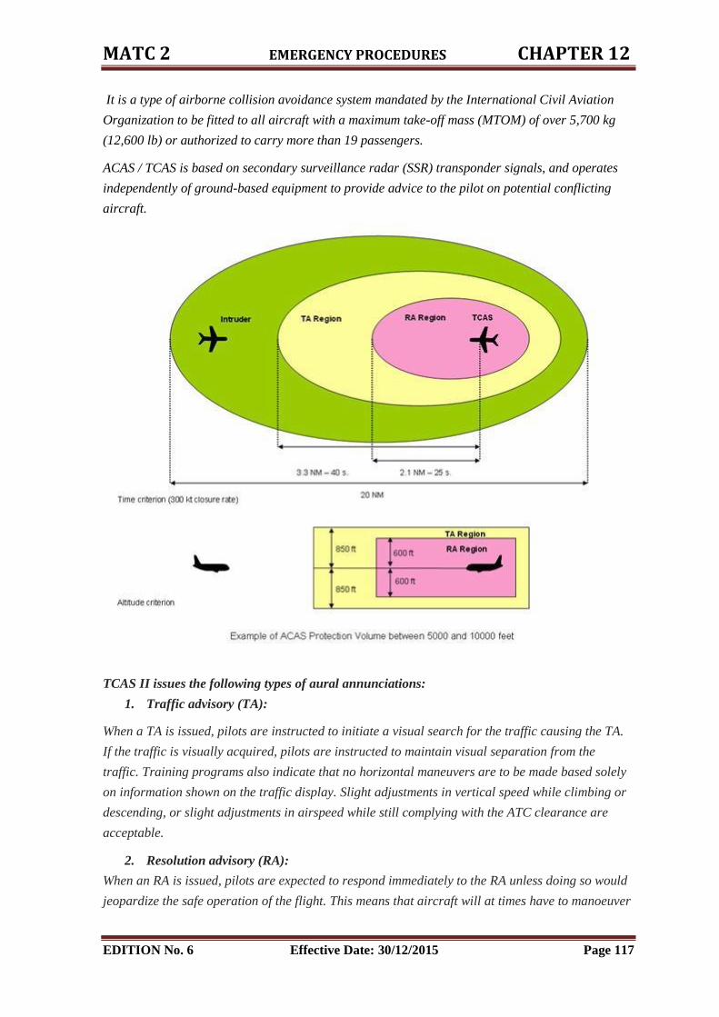
MATC 2 EMERGENCY PROCEDURES CHAPTER 12
EDITION No. 6 Effective Date: 30/12/2015 Page 117
It is a type of airborne collision avoidance system mandated by the International Civil Aviation
Organization to be fitted to all aircraft with a maximum take-off mass (MTOM) of over 5,700 kg
(12,600 lb) or authorized to carry more than 19 passengers.
ACAS / TCAS is based on secondary surveillance radar (SSR) transponder signals, and operates
independently of ground-based equipment to provide advice to the pilot on potential conflicting
aircraft.
TCAS II issues the following types of aural annunciations:
1. Traffic advisory (TA):
When a TA is issued, pilots are instructed to initiate a visual search for the traffic causing the TA.
If the traffic is visually acquired, pilots are instructed to maintain visual separation from the
traffic. Training programs also indicate that no horizontal maneuvers are to be made based solely
on information shown on the traffic display. Slight adjustments in vertical speed while climbing or
descending, or slight adjustments in airspeed while still complying with the ATC clearance are
acceptable.
2. Resolution advisory (RA):
When an RA is issued, pilots are expected to respond immediately to the RA unless doing so would
jeopardize the safe operation of the flight. This means that aircraft will at times have to manoeuver
MATC 2 EMERGENCY PROCEDURES CHAPTER 12
EDITION No. 6 Effective Date: 30/12/2015 Page 118
contrary to ATC instructions or disregard ATC instructions. In these cases, the controller is no
longer responsible for separation of the aircraft involved in the RA until the conflict is terminated.
On the other hand, ATC can potentially interfere with a pilot's response to RAs. If a conflicting
ATC instruction coincides with an RA, a pilot may assume that ATC is fully aware of the situation
and is providing the better resolution. But in reality, ATC is not aware of the RA until the RA is
reported by the pilot. Once the RA is reported by the pilot, ATC is required not to attempt to modify
the flight path of the aircraft involved in the encounter. Hence, the pilot is expected to "follow the
RA" but in practice this does not always happen.
3. Clear of conflict.
12.13.3 When unable to maintain RVSM:
1. The pilots shall notify RADAR Controller of any equipment failure, weather hazards
such as severe turbulence etc., which may affect the ability to maintain the cleared
level or the RVSM requirements. When an aircraft operating in RVSM Airspace
encounters severe turbulence due to weather or wake vortex which the pilot believes
will impact the aircraft’s capability to maintain its cleared flight level, the pilot shall
inform RADAR Controller which is required to establish either an appropriate
horizontal separation minimum, or an increased vertical separation minimum of
2000ft.
2. Where a meteorological forecast is predicting severe turbulence within the RVSM
Airspace, RADAR Controller shall determine whether RVSM should be suspended,
and, if so, the period of time, and specific flight level(s) and/or area.
3. When notified by RADAR Controller of an assigned altitude deviation of more than
300ft (90 m), the pilot shall take action to return to the cleared level as quickly as
possible.
4. In the event of a pilot advising that the aircraft is no longer capable of RVSM
operations, it is particularly important that the first ATS unit made aware of the
failure performs the necessary co-ordination with subsequent ATS units.
12.13.4 Deviations around severe weather:
If the aircraft is required to deviate laterally from track to avoid weather (e.g. thunder
storms), the pilot should request a revised clearance from RADAR Controller and
obtain essential traffic information prior to deviating. This is the case even when a
pilot expects to have to deviate by a relatively small distance (less than 10 NM).
Pilots must appreciate that RADAR Controller can only provide a revised clearance
which will continue to assure that minimum standard separations are maintained from
all other traffic, including any on adjacent tracks. When this is not possible, RADAR
Controller will advise the pilot “Unable” and will request the pilot’s intentions. The
MATC 2 EMERGENCY PROCEDURES CHAPTER 12
EDITION No. 6 Effective Date: 30/12/2015 Page 119
pilot should indicate the direction, anticipated magnitude and if appropriate the
expected altitude change of the intended deviation.
The RADAR Controller should advice the following:
1. TACC Supervisor.
2. ADOC. 3. Adjacent units if the deviation will affect their areas.

CHAPTER THIRTEEN
ON JOB TRAINING

MATC 2 On Job Training CHAPTER 13
EDITION No. 6 Effective Date: 30/12/2015 Page 120
13. ON JOB TRAINING
13.1 General Procedures:
1. OJT at Amman TACC will be carried out in accordance with the following
procedures:
a) Chief of OJT is responsible to DANS for implementation and management of
OJT.
b) OJT instructors will carry out the monitoring and training of trainee controllers,
and will brief the trainee of the objectives of each training period.
2. OJTI is responsible for:
a) Safety at all times during operational instructions, and will carry out OJT in
accordance with these instructions, and will ensure that accurate records are
kept in the training record sheet.
b) Prepare training reports as required, and submits the report to chief of OJT
within ascertain time.
13.2 Phase of Training:
The phases of training are three phases:
I. Phase 1:
1. Unit induction:
a) Objective is to familiarize the trainee with unit administration and procedures.
b) Administration by discussing the role and procedures that affect RADAR
controllers.
2. Procedures. Ensure that the trainee is aware of his/her responsibilities
including:
a) Transport.
b) Leave.
c) Sickness.
d) Shift rosters.
e) Logbooks
f) Conduct and discipline.
g) Incident reporting.
h) Amman TACC manual.
OJTI will check that the trainee is in possession of Manual of Air Traffic Services
and Amman TACC both correctly amended.
MATC 2 On Job Training CHAPTER 13
EDITION No. 6 Effective Date: 30/12/2015 Page 121
II. Phase 2 " Equipment and Operating Procedures ":
1. Objective is to familiarize the trainee with the RADAR equipment and operating
procedures to be used.
2. Equipment: ensure that the trainee is competent to use the equipment will
proceed the next phase 3 which will cover the following:
a) Voice communication system "VCS" including ATIS.
b) RADAR system.
c) Weather system.
III. Phase 3 " Practical Training ":
The Objective of this phase to demonstrate the trainee is capable of effectively
controlling air traffic in a safe, orderly and expeditious manner, and has the
knowledge of the equipment and procedures relevant to the rating and/or rating
validity.
13.3 Trainees:
1. Will attend training, briefing and instructional work period as instructed by their
OJT instructor.
2. Will work in periods when they are not engaged in practical instruction to learn the
relevant procedures.
13.4 Progress Tests:
OJTI will conduct a progress test on completion of phase 2, and chief of OJT will
conduct a progress test on completion of phase 3, and final assessment.
NOTE: chief of OJT may delegate the task of phase 3 and final assessment to
independent Examiner.
13.5 Training Report:
OJTI will prepare a training report on completion of phase 2 of training and every 10
hours during phase 3. Using the standard and /or approved form by the DANS for
ATC training report form.
13.6 Examination:
When the trainee has successfully completed the final test and has been
recommended for examination by the chief of OJT, the rating examination will be
conducted by inspector from DANS and designated examiner who shall have the
valid rating, result of the examination will be submitted to the DANS unit on the
standard form.
MATC 2 On Job Training CHAPTER 13
EDITION No. 6 Effective Date: 30/12/2015 Page 122
13.7 General Description of Rating Phases:
Each controller shall hold the procedural rating appropriate to the RADAR rating.
The controller has completed not less than three months or 180 hours whichever is
greater, satisfactory service in the provision of RADAR control service under the
supervision of certificated and appropriately instructor, and has been practically
assessed as satisfactory by authorized person only from DANS.
He or She shall satisfy the Jordan Civil Aviation Regulatory Commission regulations
" JCAR- Part 65 " " ATC – MATC I and MATC II " and AIP , as to His or Her skill
in the provision of RADAR control service and in His or Her knowledge of:
1. Airspace structure.
2. Applicable rules, regulations and source of information.
3. Air navigation facilities.
4. Air traffic equipment and its use.
5. Terrain and prominent landmarks.
6. Characteristics of air traffic and traffic flow.
7. Weather phenomena.
8. Emergency and Search and rescue plans.
9. Principles use and limitations of RADAR, other surveillance systems and
associated equipment.
10. Procedures for the provision of approach or area RADAR control services as
appropriate.
11. Procedures to ensure terrain clearance as appropriate.
13.7.1 TMA Approach Procedural Non-RADAR:
1. Phase 1: As detailed in general description phase 1 " procedures ".
2. Phase 2: In addition to general description phase 2 " equipment ", the trainee
will be briefed on the following:
1. Area of responsibility.
2. Taking over watch.
3. Out bound procedures
4. Estimates.
5. Level restrictions.
6. Stack levels and EATs.
7. Coordination inbound and outbound.
8. Visual approach procedures.
9. Instrument approaches, and landing interval.
10. Approach /terminal flow direction.
11. Diversions.
12. Royal flights.
MATC 2 On Job Training CHAPTER 13
EDITION No. 6 Effective Date: 30/12/2015 Page 123
13. Radio failure procedures.
14. Navigational aids.
15. Holding procedures.
16. Emergencies:
I. General
II. Local standby.
III. Full emergency.
IV. Aircraft accident.
V. Hi-jack or bomb threat.
VI. Fuel dumping.
17. VFR procedures.
18. Job description of approach procedural controller.
19. AQABA procedures, " approach and / or west sector " as appropriate.
3. Phase 3: The trainee will be able to demonstrate the practical skill, including:
1. Allocating STAR clearance, holding stack levels, receiving, releases
and calculating EATs.
2. Receiving, processing estimates revisions and manual preparation of
FPS.
3. Monitoring the TMA frequency and assisting the approach RADAR
controller in maintaining an up-to-date flight progress strip.
4. Passing estimates, revisions and EATs to the relevant ATC unit.
5. Alerting the TMA approach RADAR controller of any apparent
confliction evident from the traffic display, which requires resolution.
6. Coordination with the relevant En-route sector.
7. Pass departure clearances to tower.
8. Assisting the TMA approach RADAR controller in re-establishing
procedural separation in case of RADAR failure.
9. Performing other related duties which may be assigned by chief of
OJT.
NOTE: These duties could be also included within the task of TMA approach
procedural planner controller.
13.7.2 TMA Approach RADAR:
1. Phase 1: As detailed in general description phase 1 " procedures ".
2. Phase 2: In addition to general description phase 2 "equipment ", the trainee
will be briefed on the following:
MATC 2 On Job Training CHAPTER 13
EDITION No. 6 Effective Date: 30/12/2015 Page 124
1. General RADAR specifications and limitations.
2. RADAR setting up procedures.
3. SSR code allocations.
4. RADAR separation standards.
5. RADAR coordination procedures.
6. RADAR identification procedures.
7. Mode C verification procedures.
3. Phase 3: The trainee will be able to demonstrate the practical skill, including:
1. Identifying and tracking aircraft under control, by the use of RADAR.
2. Applying non-RADAR separation, when RADAR equipment is failed.
3. Maintaining an up to-date flight progress strip, in case of RADAR
failure.
4. Hand-over procedure " transferring and accepting ".
5. Co-ordination procedure has affected, before the aircraft leaves area of
Responsibility.
13.7.3 En-route Procedural Non-RADAR:
1. Phase 1: As detailed in phase 1 general description " procedures ".
2. Phase 2: In addition to general description phase2 " equipment " the trainee
will be briefed on the following:
1. Area of responsibility
2. Taking over watch.
3. Control of traffic.
4. Coordination with TMA approach control.
5. Coordination inbound/outbound.
6. Separation standards.
7. High level holding.
8. Coordination with adjacent ATC units and/or ACCs.
9. Diversions.
10. Royal flights.
11. VVIP and / or VIP flights.
12. Radio failure procedures.
13. Navigation AIDs.
14. Emergencies, high-jack, bomb threat and fuel dumping.
15. Duties of E-n-route procedural controller.
16. AQABA procedures " approach and/or west sector " as appropriate.
3. Phase 3: The trainee will demonstrate that he/she is capable to carry out the
following duties:
MATC 2 On Job Training CHAPTER 13
EDITION No. 6 Effective Date: 30/12/2015 Page 125
1. Receiving and processing of estimates and revisions from/to other
sector or ATC units and the manual preparation of flight progress strip
in case of FDO failure.
2. Monitoring the sector frequency and assisting the En-route RADAR
controller in maintaining an up to date flight progress display.
3. Pass all estimates and revisions to the relevant sector or ATC units.
4. Alert the En-route RADAR controller of any apparent confliction
evident from the traffic display, which require resolution.
5. Coordination all traffic entering or leaving the sector area of
responsibility, and all allocation of clearances to provide procedural
separation, unless RADAR separation is to be provided in accordance
with agreed procedures.
6. In the event of full RADAR failure to assist the En-route RADAR
controller in re-establishing procedural separation.
7. Allocating SSR codes as required by RADAR controller and ensuring
that the correlation process is achieved.
8. Assisting the En-route RADAR controller and file flight progress
strip.
9. Performing other related duties which may be assigned by the chief of
OJT.
NOTE: These duties could be also included within the task of OJT En-route
RADAR controller.
13.7.4 En-route RADAR:
1. Phase 1: As detailed in phase1 " general description procedures ".
2. Phase 2: In additions to general description phase 2 " equipment " the trainee
will be briefed on the following:
1. General RADAR specifications and limitations.
2. RADAR setting up procedures.
3. SSR code allocation.
4. RADAR separation standards.
5. RADAR coordination procedures.
6. RADAR identification procedures.
7. Mode C verification procedures.
3. Phase 3: The trainee will demonstrate that he/she is capable to carry out the
following duties:
a) Identifying and tracking aircraft under his/her control, effecting
RADAR control and/or RADAR separation as necessary.
b) Applying non-RADAR separation criteria when RADAR separation is
not desirable or not possible.
MATC 2 On Job Training CHAPTER 13
EDITION No. 6 Effective Date: 30/12/2015 Page 126
c) Maintaining an up to date flight progress display.
d) Accepting aircraft from and transferring aircraft to TMA terminal
RADAR unit.
e) Where co-ordination is required, ensuring that this has been carried
out before aircraft leaves sector area of responsibility.
f) Performing other related duties assigned by the chief of OJT.
13.8 TACC Forms:
Attach in APPINDEX 3.