Embed Size (px)
Citation preview

Material and Energy Efficient Busbar Systems
Proceedings of EMC 2011 1
Material and Energy Efficient Busbar Systems
in Zinc and Copper plants Dr.-Ing. Wolfgang Reiser, Dipl.-Ing. Ulrich Zimmer
Vision Electric GmbH
66851 Schwanenmühle
Germany
Abstract
Industry plants with high electric direct currents in the range of several 100 kA, like graph-
itization plants and electrolysis for production of chlorine, aluminium, copper, zinc, etc. use
busbar systems to connect rectifiers to process. Busbar systems provide sufficiently large
cross sections to keep the transfer power losses in reasonable limits and are at the same
time inherently stable to master the resulting static and dynamic forces. Often older indus-
try plants are used as an example for design, material and dimensions without considering
the possibilities of the new 21st century: current densities are used to determine cross sec-
tions, questions about the right material are not asked and side conditions like magnetic
field evaluation are not respected.
Examples of installed busbar systems in copper and zinc plants will show how it is possi-
ble to improve operation data – which means higher energy efficiency – and at the same
time increase efficiency on material usage. E.g. the tender specification of a busbar sys-
tem for a new copper electrolysis required more than 700 t of copper. Against all expecta-
tions this was realized with approx. 500 t of copper plus 50 t of aluminium. Optimal usage
of the busbar material led to this enormous material efficiency with improved operational
data at the same time. This was only possible by a total new design taking into considera-
tion all influencing parameters.
The new material and energy efficient design will be illustrated using drawings, graphs and
pictures.
Wolfgang Reiser / Ulrich Zimmer
Proceedings of EMC 2011 2
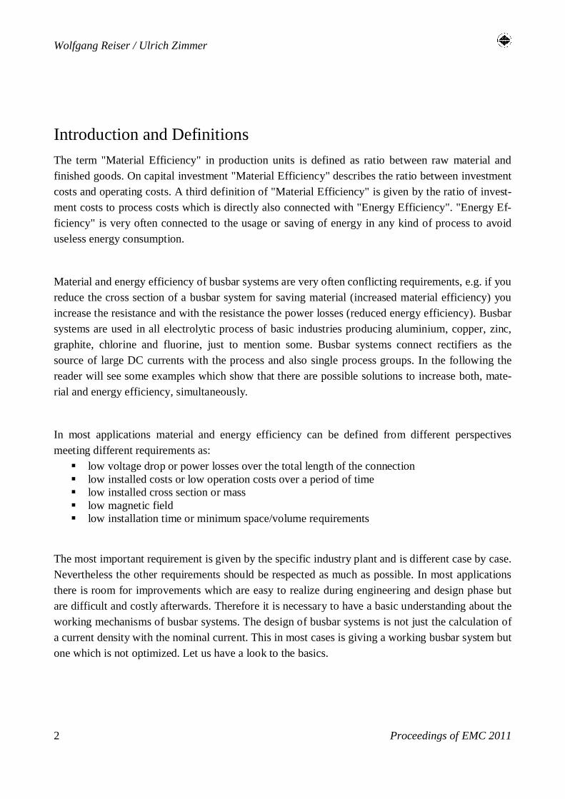
Introduction and Definitions
The term "Material Efficiency" in production units is defined as ratio between raw material and
finished goods. On capital investment "Material Efficiency" describes the ratio between investment
costs and operating costs. A third definition of "Material Efficiency" is given by the ratio of invest-
ment costs to process costs which is directly also connected with "Energy Efficiency". "Energy Ef-
ficiency" is very often connected to the usage or saving of energy in any kind of process to avoid
useless energy consumption.
Material and energy efficiency of busbar systems are very often conflicting requirements, e.g. if you
reduce the cross section of a busbar system for saving material (increased material efficiency) you
increase the resistance and with the resistance the power losses (reduced energy efficiency). Busbar
systems are used in all electrolytic process of basic industries producing aluminium, copper, zinc,
graphite, chlorine and fluorine, just to mention some. Busbar systems connect rectifiers as the
source of large DC currents with the process and also single process groups. In the following the
reader will see some examples which show that there are possible solutions to increase both, mate-
rial and energy efficiency, simultaneously.
In most applications material and energy efficiency can be defined from different perspectives
meeting different requirements as:
§ low voltage drop or power losses over the total length of the connection § low installed costs or low operation costs over a period of time § low installed cross section or mass § low magnetic field § low installation time or minimum space/volume requirements
The most important requirement is given by the specific industry plant and is different case by case.
Nevertheless the other requirements should be respected as much as possible. In most applications
there is room for improvements which are easy to realize during engineering and design phase but
are difficult and costly afterwards. Therefore it is necessary to have a basic understanding about the
working mechanisms of busbar systems. The design of busbar systems is not just the calculation of
a current density with the nominal current. This in most cases is giving a working busbar system but
one which is not optimized. Let us have a look to the basics.

Material and Energy Efficient Busbar Systems
Proceedings of EMC 2011 3
Basic Equation of a busbar system
The purpose of a busbar system is to conduct electrical current from point A to point B. In almost
all cases copper and aluminium and their alloys are used as conductors because both metals have
reasonable high conductivity against material costs. E.g. silver is a better conductor but is by factor
50 more expensive than copper.
In the following we are talking about DC busbar systems with a value of between 20 and 500 kA
nominal current. The conductor has an electrical resistance R and is heated up while the current is
running as long as the balance is reached between heat dissipation and power loss. The following
graph is illustrating this relationship.
Figure 1: Heat Equation of Busbars
Power losses P in the busbar are created according to P = I² x R. The resistance R itself alters with
temperature T and is a function of the cross section A.

Wolfgang Reiser / Ulrich Zimmer
Proceedings of EMC 2011 4
The heat dissipation can be subdivided into the two major parts, convection and radiation cooling
which are both functions of the conductor surface area. Radiation in this context means the net ra-
diation which is the difference between the emission and immission taking also into account radia-
tion sources in the near environment of the busbar system.
Radiation is a function of Temperature T and the surface condition of the conductor mainly repre-
sented by emission coefficient ε which has a value between 0 and 1. A value of 1 is characterizing a
black radiation emitter. Convection cooling consists of laminar and turbulent flow. So the basic
energy equation of a busbar is
Power Losses = Radiation + Laminar Flow + Turbulent Flow
which can be solved in a multi-step iterative process reaching a balance between both sides and a
constant temperature giving the operating temperature of the busbar system. In most cases the op-
eration temperature is an important value because it is limited by the surrounding and insulating
parts of the busbar system which are in most cases plastic parts. Additionally other side conditions
like ambient temperature, altitude, moving air, surface roughness, etc. need to be respected in the
equation, too.
The solution of this simple equation leads to a very astonishing result: At a given temperature level
of the busbar system we can reduce the cross section of the conductor by up to 40% without in-
creasing the temperature of the conductor. In other words: It is possible to save 40% of the material
and not increasing the temperature of the conductor. This is possible by choosing the right format
which offers an optimum ratio between cross section (power losses) and conductor surface (heat
dissipation). The following figure gives an illustration about the saving ratio. Both conductors have
equal width and height.
100% cross section
60% cross section
Figure 2: Conductors with different cross section but equal current carrying capacity

Material and Energy Efficient Busbar Systems
Proceedings of EMC 2011 5
Differences between both concepts are in power losses, voltage drops and rigidity which have influ-
ence on static and dynamic loads in case of e.g. short circuit.
Copper or Aluminium
The material choice is the most critical decision in the design of the busbar. Copper or aluminium,
grade and format, air or water cooled, enclosed or not enclosed, painted or unpainted, welded or
bolted connections and many more different questions have to be answered. Silver is the best metal
conductor but very expensive. The conductivity of copper is close to silver but the cost of copper
was factor 100, today factor 50, lower than the cost of silver. So copper was the first choice for
conducting current. Copper also provides very good surface contact characteristics which allow
reliable and easy bolting of conductor elements.
During the decades another metal became very attractive: aluminium. Aluminium has only 60% of
the conductivity of copper but offers also advantages against copper. The density is 30% of copper
(2,7 against 8,9 kg/dm³). For the same conductor resistance you need only 50% of the mass of alu-
minium for the substitution of copper.
The price per kg or ton of aluminium was equal with the price of copper in the first years of the new
millennium. In the meantime this relation changed dramatically: Copper today is sold per mass unit
between factor 3 and 4 higher than aluminium. Taking the price difference into consideration alu-
minium has a today cost advantage of factor 6 to 8 on the pure metal price. The development of
copper and aluminium prices are shown below

Wolfgang Reiser / Ulrich Zimmer
Proceedings of EMC 2011 6
Figure 3: The thin line represents the stock quantity of copper in tons whereas the thicker line is
giving the price fluctuation over the last years
Still, despite of the large cost advantage of aluminium there are good reasons for using copper:
available space, easy connection method on site, corrosion resistance, etc. Especially corrosion re-
sistance is an argument often used but not valid in all cases. E.g. in chlorine plants in some compa-
nies it is forbidden to use aluminium below electrolysers because aluminium is washed away by
caustic running out of the piping system of the electrolyser. Additional protection is solving that
problem and today you find aluminium busbars below new chlorine electrolysers.

Material and Energy Efficient Busbar Systems
Proceedings of EMC 2011 7
Figure 4: The thin line represents the stock quantity of aluminium in tons whereas the thicker line
is giving the price fluctuation over the last years
The final answer to the question of choice is to use copper and aluminium whenever there is an ad-
vantage for one of the metals. E.g. the requirement for a connection over a long distance is low voltage drop without increase over the years combined with low material costs.
The only possibility for keeping the voltage drop constant over years is to weld the single busbar
elements together. Both, aluminium and copper can be welded on site. Aluminium is offering lower
material costs then copper. Then the choice might be using an oversized aluminium bar to keep the
voltage drop very low. The connections to the end devices
Copper-Aluminium Connections
The following example is used to explain the decision process on the following requirements:
1. Long outdoor distance (< 120 m) between rectifier and cell house
2. Extremely low voltage drop because rectifier transformer is on his maximum voltage
3. No additional voltage drop over the design lifetime of 30 years

Wolfgang Reiser / Ulrich Zimmer
Proceedings of EMC 2011 8
4. Low material and installation cost
5. Connections to the devices in the cell room with copper
Both, copper and aluminium can be used for long distances and low voltage drops, calculating the
right cross section (requirements 1 & 2). Bolts and nuts connections will always result in additional
voltage drop over years due to corrosion between the contact surfaces of busbar elements. The only
way to fulfil requirement 3 is welding. Both, copper and aluminium can be welded on site but alu-
minium welding is much easier: Therefore in most cases copper is bolted and aluminium is welded
on site.
The next requirement is making the difference: copper is much more expensive than aluminium.
But the last requirement asks for copper. Therefore copper-aluminium transition pieces like
presswelded, MIG-welded, explosion bonded or other methods are necessary to provide a good
copper to aluminium connection. The following pictures will show several examples.
Figure 5: Large aluminium bars with presswelded copper flexibles, directly connected

Material and Energy Efficient Busbar Systems
Proceedings of EMC 2011 9
Figure 6: Examples of copper terminals welded to aluminium flexibles
Copper/Aluminium transition joints
Another application for copper-aluminium connection is found in zinc electrolysis: the cathode con-
tact which is aluminium welded to the cathode header bar and the copper contact which is making
the transition to end and intermediate cell bars. In many cases the copper-aluminium bond is real-
ized by explosion bonding or similar methods. Nevertheless corrosion takes place due to the pres-
ence of strong electrolyte vapours coming out of the cell.
Improved efficiency in this case is understood as increased life time of the copper-aluminium inter-
face. By just using little more of copper, the remaining interface area is much better protected and
therefore the whole piece has much longer lifetime. The following figure shows the difference.

Wolfgang Reiser / Ulrich Zimmer
Proceedings of EMC 2011 10
Figure 7: Improved material efficiency under heavy corrosive environment
Watercooled Bus Bars
In some cases space problems do not allow to use large aluminium or copper conductor profiles
which are normally aircooled. Reduction of cross section is only possible by a higher cooling effect
which keeps the conductor temperature on a permissible level. The technical solution in industry is
forced water cooling providing a conductor which is hollow or has an integrated piping system.
With watercooled bus bar systems the conductor cross section can be reduced by factor 5 – 10, de-
pending on the application. Disadvantages are stray currents (mainly through the water pipe connec-
tion), increased power losses and voltage drops. Additional equipment like cooling water circuit
with necessary pumps, heat exchangers, valves and instrumentation has to be integrated. In general
water cooled systems are not as robust as air cooled systems and need higher maintenance attention.
The following pictures show different types of watercooled busbar systems.

Material and Energy Efficient Busbar Systems
Proceedings of EMC 2011 11
Figure 8: Watercooled aluminium busbar with stainless steel water pipe
Figure 9: Watercooled copper profile with integrated cooling hole
Cooling drill-hole

Wolfgang Reiser / Ulrich Zimmer
Proceedings of EMC 2011 12
Aluminium in Copper Electrolysis
Many copper electrolysis do not want to use aluminium busbars in the cell room. This arises from some experience in electrorefining not electrowinning:
An electrorefining electrolyte contains a wide range of metallic cations coming from the dissolution
of the impure copper anode. Among these are arsenic and antimony. If the acidic electrolyte con-
tacts aluminium busbars hydrogen is evolved which can combine with the arsenic and antimony to
form arsine and stibine respectively. Both of these are toxic gases. This situation gives rise to the
knee jerk reaction of "no aluminium busbars in copper plants".
However in copper refineries such bars can be quite safely used if the aluminium is confined to the
trunk bars away from the electrolyte and even for front and back bars if properly shielded from
electrolyte drips by plastic sheeting.
For almost all electrowinning plants, especially those associated with solvent extraction plants,
there is no arsenic or antimony present in the electrolyte and aluminium can be used for busbars
with impunity. Shielding and drip sheets may be provided where electrolyte dripping occurs simply
to protect the bars from acid attack but there are no safety concerns.

Material and Energy Efficient Busbar Systems
Proceedings of EMC 2011 13
Current Distribution at End Cells
Transferring the operation current from rectifier to cell room is in most cases not a challenge. The
correct and efficient distribution of the current to the first cells is in many cases not done in the
most efficient way.
Figure 10: Example 1 – Current distribution from riser bar to cathodes/anodes with low number of
riser bars
Example 1 with two riser bars between the main busbar system and the end cell is illustrating the
situation. For better understanding rounded figures for currents are used. The thickness of the riser
bars is assumed to be 20 mm which is then able to carry 2,000 A in this example. The distance be-
tween the riser bars is approx. three times the width of one riser bar. Two times 250 A is running
straight to the cell across the end cell bar. The remaining 750 A on both sides are running thru the
end cell bar sideways. Consequently the cross section of the whole end cell bar has to be designed
to carry his current or at least 500 A as an average value. Normally the same format of the end cell
bar and the intercell bar is used, even not necessary due to different current flow and current densi-
ties.
Example 2 is using double number of riserbars with only half the thickness of 10 mm. First of all
this gives double surface at every bolted connection which means half of the contact power losses.
Main advantage is the more equal current distribution and feeding of the end cell bar.

Wolfgang Reiser / Ulrich Zimmer
Proceedings of EMC 2011 14
Figure 11: Example 2 – Current distribution from riser bar to cathodes/anodes with double number
of riser bars
A current of 500 A from each riser bar is running across the end cell bar directly to the cell as in
example 1. The remaining 500 A of the riser bar current is running lengthwise the end cell bar, rec-
tangular to the riser bar, split into both sides giving just 250 A to each side. In example 2 one riser
bar carries half the current than that in example 1. The current running alongside the end cell bar is
only 250 A (one third) compared with the current of 750 A of example 1. Therefore the cross sec-
tion of example 2 can be reduced and will still give better efficiency in terms of reduced power
losses. Together with the end cell bars the cross section of all intercell busbars can be reduced giv-
ing a real saving of material without any negative aspect.
The limitation for the reduction of the cross section is the mechanical integrity of the of the end cell
bar. The end cell and intercell bars are loaded with the weight of anodes and cathodes. A tension
analysis as shown in the next picture is helpful in finding the right thickness.

Material and Energy Efficient Busbar Systems
Proceedings of EMC 2011 15
Figure 12; Result of the tension test analysis of endcell bar
Power losses PL = f (I²) which means that at places with double current density you find four times
the power losses. This makes Example 1 even worse because this explains local hot spots.
Unequal current distribution leads to unequal feeding of cathodes. This effect can be noticed in
some zinc or copper plants where the outer plates of the first, second or sometimes third cell do not
carry as much metal as the inner plates. Lost metal winning is the consequence. This shows that
material efficiency means optimum usage of material in making the process more efficient and
which does not need any additional material but just know-how to use it best. The picture below
shows a situation with 12 riser busbars to get an optimized current distribution even in the first
cells.
As a second improvement bolt connections between riser bars and the feed plates are outside of the
corrosive area of the electrolyte. This is achieved by welding the feed plates to the end cell bars
which gives a molecular bond of the same material in the acid vapour loaded area. The bolt and nut
connection is not any more subject to heavy corrosion – the contact resistance will remain low for a
long time.

Wolfgang Reiser / Ulrich Zimmer
Proceedings of EMC 2011 16
Figure: 12 riser bars feeding the end cell with a current of approx. 200 kA which leads to a
nominal current of 16,5 kA per riser bar.
Material and Energy Efficient Busbar Systems
Proceedings of EMC 2011 17
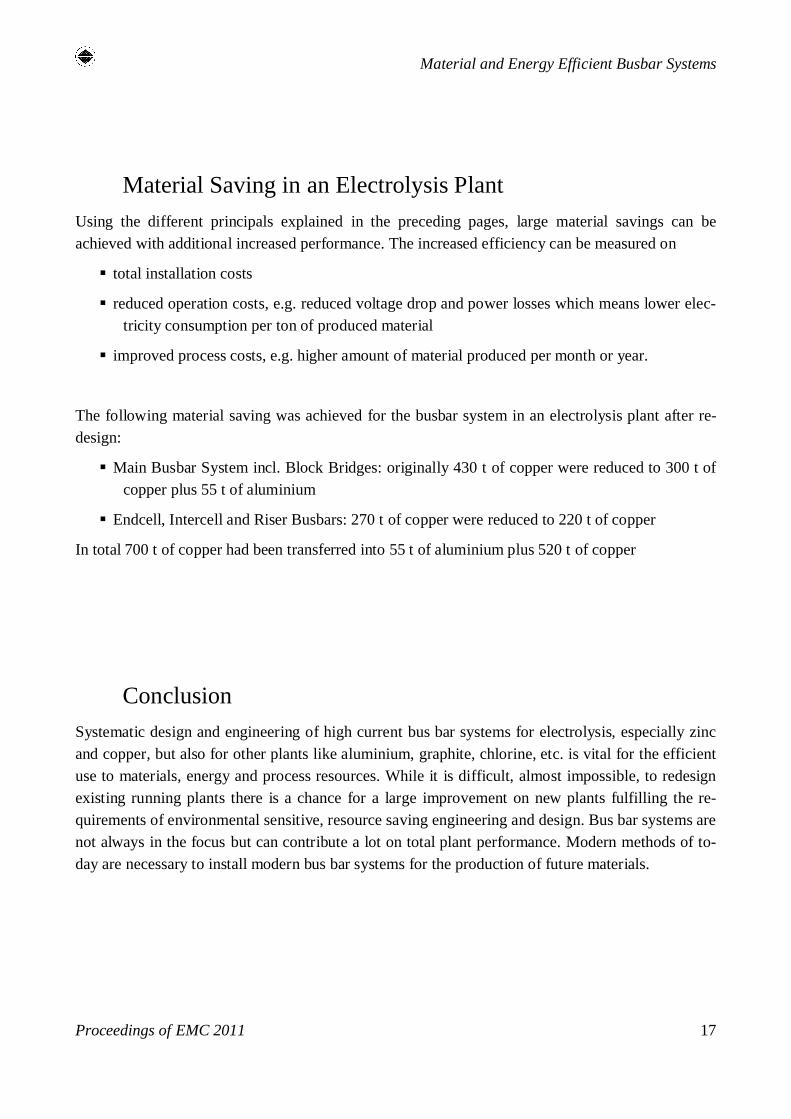
Material Saving in an Electrolysis Plant
Using the different principals explained in the preceding pages, large material savings can be
achieved with additional increased performance. The increased efficiency can be measured on
§ total installation costs
§ reduced operation costs, e.g. reduced voltage drop and power losses which means lower elec-
tricity consumption per ton of produced material
§ improved process costs, e.g. higher amount of material produced per month or year.
The following material saving was achieved for the busbar system in an electrolysis plant after re-
design:
§ Main Busbar System incl. Block Bridges: originally 430 t of copper were reduced to 300 t of
copper plus 55 t of aluminium
§ Endcell, Intercell and Riser Busbars: 270 t of copper were reduced to 220 t of copper
In total 700 t of copper had been transferred into 55 t of aluminium plus 520 t of copper
Conclusion
Systematic design and engineering of high current bus bar systems for electrolysis, especially zinc
and copper, but also for other plants like aluminium, graphite, chlorine, etc. is vital for the efficient
use to materials, energy and process resources. While it is difficult, almost impossible, to redesign
existing running plants there is a chance for a large improvement on new plants fulfilling the re-
quirements of environmental sensitive, resource saving engineering and design. Bus bar systems are
not always in the focus but can contribute a lot on total plant performance. Modern methods of to-
day are necessary to install modern bus bar systems for the production of future materials.