Embed Size (px)
Citation preview
Material Induced Changes of Antenna Performancein Vehicular Applications
Gerald Artner, Robert Langwieser and Christoph F. MecklenbraukerVienna University of Technology, Institute of Telecommunications
Christian Doppler Laboratory for Wireless Technologies for Sustainable MobilityVienna, Austria
Email: [email protected]
Abstract—Recent advancements in production materials forcars replace well-known ground plane materials for vehicularantennas. Carbon-fiber composites (CFC’s) replace steel as chas-sis material, which leads to reduced radiation efficiency. As theproduction processes of shark-fin antenna modules shift towardslaser direct structuring (LDS), it is investigated, if antennaefficiency can be increased by the introduction of a LDS groundplane. Differences in antenna performance are presented on theexample of simple LDS and wire monopole-antennas for 5.9GHz(IEEE 801.11p, ITS G5). Gain, efficiency, return loss and theradiation patterns of an LDS design, a CFC and an aluminumground plane are compared.
I. INTRODUCTION
The state of the art of vehicular antenna design are shark-fin modules that are mounted at the rear center of the carroof. These modules include antennas for mobile telephony,car-to-car and car-to-infrastructure communication, positioningand entertainment services. Often several printed circuit boards(PCB’s) are enclosed inside a radome [1].
A process called laser direct structuring (LDS) from LPKFLaser & Electronics AG allows the application of metal layerson three-dimensional plastic structures [2]. The design ofshark-fin modules as molded interconnect devices (MID’s)allows the antennas to be placed directly on the radome [3].In cell phones LDS antennas are already widely used [4]. Alog.-periodic antenna in LDS MID technology was presentedin [5].
Carbon-fiber composites (CFC’s) replace steel and alu-minum as car body materials. CFC’s consist of carbon-fibersmolded together with an epoxy resin, they are light-weight andhave high mechanical stability. CFC’s are electric conductors.Their electrical properties depend on fiber-alignment, fiber-density and used matrix [6], [7].
In our recent work we have found that, for simplemonopole antennas on circular ground planes and severalCFC’s, the substitution of an aluminum ground plane by a CFCdoes not significantly influence the radiation pattern and thatthe CFC reduces the efficiency of the monopole antenna.[8]
To mitigate the losses in the CFC ground plane, it might befeasible to include an LDS ground plane as part of LDS shark-fin modules. In this work differences in antenna performanceon different ground plane materials are measured. Simplemonopole antennas for 5.9GHz are mounted onto groundplanes made of aluminum, CFC and one from an LDS process.
The antennas and investigated ground plane materials aredescribed in Section II. In Section III the measurement setupis explained. The measurement results are presented in Sec-tion IV. In Section V the presented work is summarized.
II. MANUFACTURED MONOPOLE ANTENNAS
A wire monopole and an LDS monopole for 5.9GHzare investigated on ground planes made from three differentmaterials.
A. Investigated monopoles
An LDS design and a wire monopole are investigated.
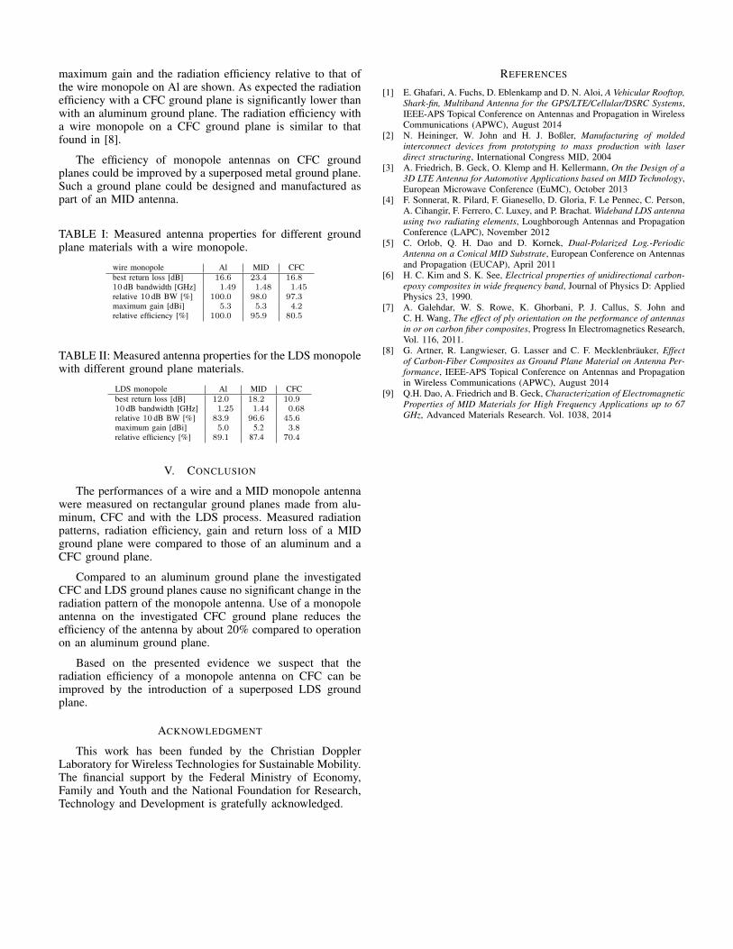
The LDS design of the monopole is a 10×2mm rectangleplaced on a 30×20×3mm cuboid, made of Xantar LDS 3720,with the LDS-process. Xantar LDS 3720 from MitsubishiEngineering has εr ≈ 2.7 and tanδ ≈ 0.005 [9]. The plasticis metalized with 6-8µm Cu, 5-7µm Ni and 0.1µm Au. Asthe exact material properties from [9] were not available at thetime of production, the resonance frequency is slightly shiftedas depicted in Figure 4b.
As comparison a simple piece of straight wire is solderedto the inner conductor of an SMA connector. The wires arethen cut to the appropriate length, such that the S11 resonanceis at the desired frequency.
B. Investigated ground planes
All ground planes are quadratic with side lengths of150mm.
The ground plane denoted as Al is a 2mm thick aluminumplate.
The second investigated ground plane is a 3mm thick plateof XANTAR LDS 3720 with an LDS metalized top layer. Thesurface of the LDS ground plane is quite rough (accordingto the manufacturer 10-50µm). The LDS ground plane wasdesigned to be contacted with an SMA-flange. However, thatprototype yielded questionable measurement results, either dueto poor contacting between the four flange screws and the LDSground plane with conductive epoxy, or due to insufficientshielding of the inner conductor by only four screws. There-fore, measurement results from a second prototype, wherethe outer conductor of a semi-rigid coaxial cable is soldereddirectly to the LDS ground plane, are presented in this paper.The assembled LDS antenna prototype is depicted in Figure 1.
978-1-4799-7473-3/15/$31.00 ©2015 IEEEFrom IEEE International Conference on Microwaves, Communications, Antennas and Electronic Systems (COMCAS 2015), 2 - 4 November 2015, Tel Aviv, Israel
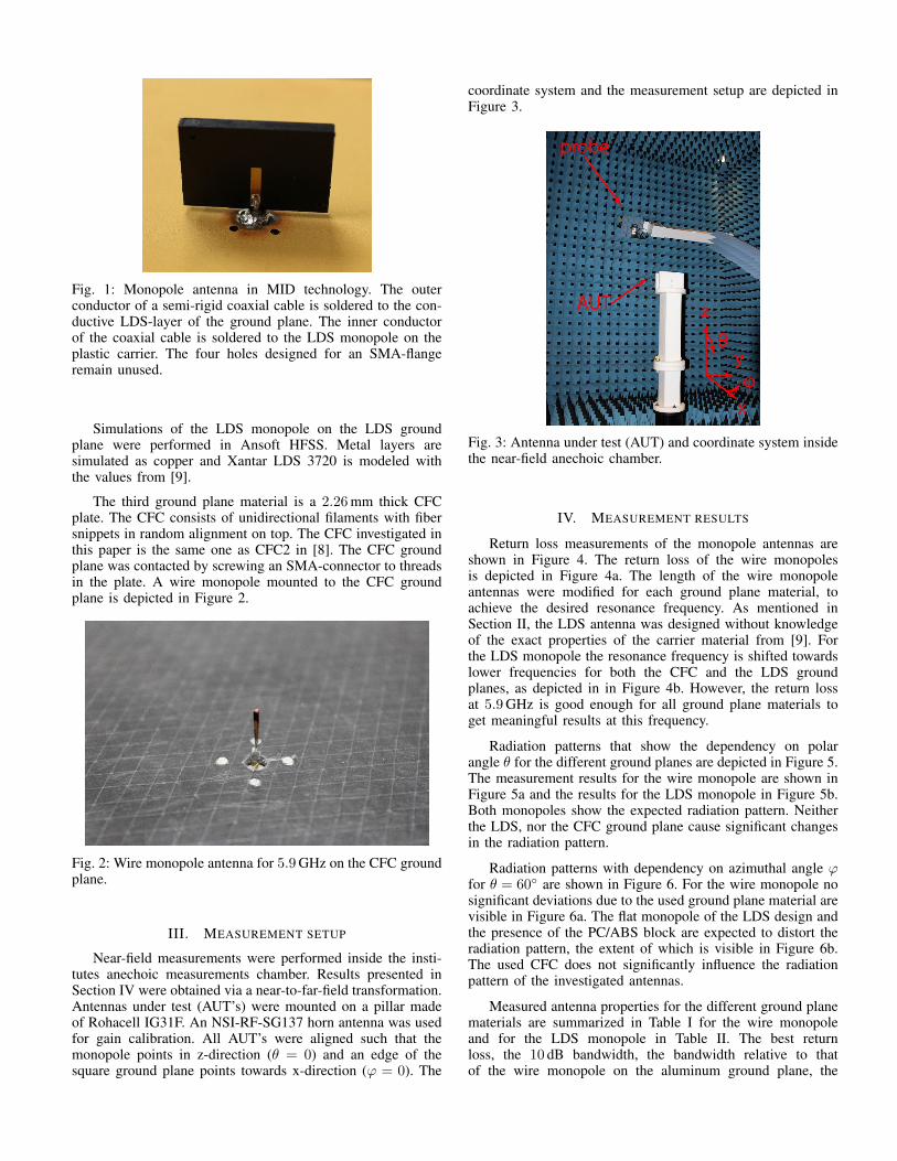
Fig. 1: Monopole antenna in MID technology. The outerconductor of a semi-rigid coaxial cable is soldered to the con-ductive LDS-layer of the ground plane. The inner conductorof the coaxial cable is soldered to the LDS monopole on theplastic carrier. The four holes designed for an SMA-flangeremain unused.
Simulations of the LDS monopole on the LDS groundplane were performed in Ansoft HFSS. Metal layers aresimulated as copper and Xantar LDS 3720 is modeled withthe values from [9].
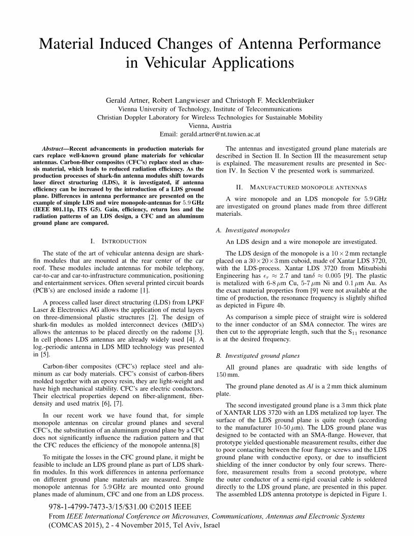
The third ground plane material is a 2.26mm thick CFCplate. The CFC consists of unidirectional filaments with fibersnippets in random alignment on top. The CFC investigated inthis paper is the same one as CFC2 in [8]. The CFC groundplane was contacted by screwing an SMA-connector to threadsin the plate. A wire monopole mounted to the CFC groundplane is depicted in Figure 2.
Fig. 2: Wire monopole antenna for 5.9GHz on the CFC groundplane.
III. MEASUREMENT SETUP
Near-field measurements were performed inside the insti-tutes anechoic measurements chamber. Results presented inSection IV were obtained via a near-to-far-field transformation.Antennas under test (AUT’s) were mounted on a pillar madeof Rohacell IG31F. An NSI-RF-SG137 horn antenna was usedfor gain calibration. All AUT’s were aligned such that themonopole points in z-direction (θ = 0) and an edge of thesquare ground plane points towards x-direction (ϕ = 0). The
coordinate system and the measurement setup are depicted inFigure 3.
Fig. 3: Antenna under test (AUT) and coordinate system insidethe near-field anechoic chamber.
IV. MEASUREMENT RESULTS
Return loss measurements of the monopole antennas areshown in Figure 4. The return loss of the wire monopolesis depicted in Figure 4a. The length of the wire monopoleantennas were modified for each ground plane material, toachieve the desired resonance frequency. As mentioned inSection II, the LDS antenna was designed without knowledgeof the exact properties of the carrier material from [9]. Forthe LDS monopole the resonance frequency is shifted towardslower frequencies for both the CFC and the LDS groundplanes, as depicted in in Figure 4b. However, the return lossat 5.9GHz is good enough for all ground plane materials toget meaningful results at this frequency.
Radiation patterns that show the dependency on polarangle θ for the different ground planes are depicted in Figure 5.The measurement results for the wire monopole are shown inFigure 5a and the results for the LDS monopole in Figure 5b.Both monopoles show the expected radiation pattern. Neitherthe LDS, nor the CFC ground plane cause significant changesin the radiation pattern.
Radiation patterns with dependency on azimuthal angle ϕfor θ = 60◦ are shown in Figure 6. For the wire monopole nosignificant deviations due to the used ground plane material arevisible in Figure 6a. The flat monopole of the LDS design andthe presence of the PC/ABS block are expected to distort theradiation pattern, the extent of which is visible in Figure 6b.The used CFC does not significantly influence the radiationpattern of the investigated antennas.
Measured antenna properties for the different ground planematerials are summarized in Table I for the wire monopoleand for the LDS monopole in Table II. The best returnloss, the 10 dB bandwidth, the bandwidth relative to thatof the wire monopole on the aluminum ground plane, the

4 5 6 7 8
0
-5
-10
-15
-20
-25frequency / GHz
LDSCFC
Al
|S11
| / d
B
(a) Return loss of wire monopoles
3 4 5 6 7
0
-5
-10
-15
-20
LDSCFC
Al
HFSS
frequency / GHz
|S11
| / d
B
(b) Return loss of LDS monopoles
Fig. 4: Measured return loss of the monopole antennas with different ground plane materials.
15°30°
45°
60°
75°
90°
105 °
120 °
135 °
150 °165 ° 180 ° 165°
150°
135°
120 °
105 °
90°
75°
60°
45°
30°15°
0.2
0.4
0.6
0.8
LDSCFC
Al
θ=0°φ = 0° φ = 180°
(a) Radiation pattern of wire monopoles
15°30°
45°
60°
75°
90°
105 °
120 °
135 °
150 °165 ° 180 ° 165°
150°
135°
120°
105°
90°
75°
60°
45°
30° 15°
0.2
0.4
0.6
0.8
LDSCFC
Al
HFSS
θ=0°φ = 0° φ = 180°
(b) Radiation pattern of LDS monopoles
Fig. 5: Radiation patterns of wire and LDS monopoles with different ground plane materials. Dependence of polar angle θ atazimuthal angle ϕ = 0◦ (left side) and ϕ = 180◦ (right side).
15°30°
45°
60°
75°
90°
105 °
120 °
135 °
150 °165 ° ±180 °−165°
−150°
−135°
−120°
−105°
−90°
−75°
−60°
−45°
−30°−15°
0.2
0.4
0.6
0.8
LDSCFC
Al
φ=0°
(a) Radiation pattern of wire monopoles
15°30°
45°
60°
75°
90°
105 °
120 °
135 °
150 °165 ° ±180 °−165°
−150°
−135°
−120°
−105°
−90°
−75°
−60°
−45°
−30°−15°
0.2
0.4
0.6
0.8
LDSCFC
Al
HFSS
φ=0°
(b) Radiation pattern of LDS monopoles
Fig. 6: Radiation patterns of wire and LDS monopoles with different ground plane materials. Dependence of azimuthal angle ϕat polar angle θ = 60◦.
maximum gain and the radiation efficiency relative to that ofthe wire monopole on Al are shown. As expected the radiationefficiency with a CFC ground plane is significantly lower thanwith an aluminum ground plane. The radiation efficiency witha wire monopole on a CFC ground plane is similar to thatfound in [8].
The efficiency of monopole antennas on CFC groundplanes could be improved by a superposed metal ground plane.Such a ground plane could be designed and manufactured aspart of an MID antenna.
TABLE I: Measured antenna properties for different groundplane materials with a wire monopole.
wire monopole Al MID CFCbest return loss [dB] 16.6 23.4 16.810 dB bandwidth [GHz] 1.49 1.48 1.45relative 10 dB BW [%] 100.0 98.0 97.3maximum gain [dBi] 5.3 5.3 4.2relative efficiency [%] 100.0 95.9 80.5
TABLE II: Measured antenna properties for the LDS monopolewith different ground plane materials.
LDS monopole Al MID CFCbest return loss [dB] 12.0 18.2 10.910 dB bandwidth [GHz] 1.25 1.44 0.68relative 10 dB BW [%] 83.9 96.6 45.6maximum gain [dBi] 5.0 5.2 3.8relative efficiency [%] 89.1 87.4 70.4
V. CONCLUSION
The performances of a wire and a MID monopole antennawere measured on rectangular ground planes made from alu-minum, CFC and with the LDS process. Measured radiationpatterns, radiation efficiency, gain and return loss of a MIDground plane were compared to those of an aluminum and aCFC ground plane.
Compared to an aluminum ground plane the investigatedCFC and LDS ground planes cause no significant change in theradiation pattern of the monopole antenna. Use of a monopoleantenna on the investigated CFC ground plane reduces theefficiency of the antenna by about 20% compared to operationon an aluminum ground plane.
Based on the presented evidence we suspect that theradiation efficiency of a monopole antenna on CFC can beimproved by the introduction of a superposed LDS groundplane.
ACKNOWLEDGMENT
This work has been funded by the Christian DopplerLaboratory for Wireless Technologies for Sustainable Mobility.The financial support by the Federal Ministry of Economy,Family and Youth and the National Foundation for Research,Technology and Development is gratefully acknowledged.
REFERENCES
[1] E. Ghafari, A. Fuchs, D. Eblenkamp and D. N. Aloi, A Vehicular Rooftop,Shark-fin, Multiband Antenna for the GPS/LTE/Cellular/DSRC Systems,IEEE-APS Topical Conference on Antennas and Propagation in WirelessCommunications (APWC), August 2014
[2] N. Heininger, W. John and H. J. Boßler, Manufacturing of moldedinterconnect devices from prototyping to mass production with laserdirect structuring, International Congress MID, 2004
[3] A. Friedrich, B. Geck, O. Klemp and H. Kellermann, On the Design of a3D LTE Antenna for Automotive Applications based on MID Technology,European Microwave Conference (EuMC), October 2013
[4] F. Sonnerat, R. Pilard, F. Gianesello, D. Gloria, F. Le Pennec, C. Person,A. Cihangir, F. Ferrero, C. Luxey, and P. Brachat. Wideband LDS antennausing two radiating elements, Loughborough Antennas and PropagationConference (LAPC), November 2012
[5] C. Orlob, Q. H. Dao and D. Kornek, Dual-Polarized Log.-PeriodicAntenna on a Conical MID Substrate, European Conference on Antennasand Propagation (EUCAP), April 2011
[6] H. C. Kim and S. K. See, Electrical properties of unidirectional carbon-epoxy composites in wide frequency band, Journal of Physics D: AppliedPhysics 23, 1990.
[7] A. Galehdar, W. S. Rowe, K. Ghorbani, P. J. Callus, S. John andC. H. Wang, The effect of ply orientation on the performance of antennasin or on carbon fiber composites, Progress In Electromagnetics Research,Vol. 116, 2011.
[8] G. Artner, R. Langwieser, G. Lasser and C. F. Mecklenbrauker, Effectof Carbon-Fiber Composites as Ground Plane Material on Antenna Per-formance, IEEE-APS Topical Conference on Antennas and Propagationin Wireless Communications (APWC), August 2014
[9] Q.H. Dao, A. Friedrich and B. Geck, Characterization of ElectromagneticProperties of MID Materials for High Frequency Applications up to 67GHz, Advanced Materials Research. Vol. 1038, 2014