Embed Size (px)
Citation preview
MATERIAL PROPERTIES AFFECTING THE MACHINABILITY OF
INCONEL 718
Maria Krook1, Viktor Recina
2, Birger Karlsson
1
1Department of Materials and Manufacturing Technology, Chalmers University of Technology,
SE-412 96 Göteborg, Sweden 2Volvo Aero Corporation, SE-461 81 Trollhättan, Sweden
Keywords: Machinability, Cemented carbide tool, Carbides, Microstructure
Abstract
The machinability of Inconel 718 was studied. In part I, wear on cemented carbide tool inserts
from turning operations on low pressure turbine cases were measured and correlated to material
properties like chemical composition, microstructure and strength. This study showed that
carbide forming elements like titanium and niobium are affecting the machinability negatively.
Carbides are hard and abrasive particles that wear down the tool inserts. It was also concluded
that strength are of minor importance to machinability on fully heat treated Inconel 718 in the
range tested. In part II, the influence of microstructure on machinability was studied on designed
work material. It was concluded that grain size has a large impact on machinability due to
deformation hardening. It was also seen that the role of -phase seems to be of minor importance
for the machinability.
Introduction
Machining of nickel based superalloys to complicated parts is often a challenging issue
associated with large costs. Variations in materials microstructures caused by differences in
chemical composition, casting and forging techniques as well as heat treatments may lead to
variations in machinability. A technically important example is manufacturing of turbine cases
for jet engines. The present study deals with the machining behaviour during manufacturing of
low pressure turbine cases for large commercial engines. These cases represent an important
business area at Volvo Aero Corporation, presently contributing with about 70 % of the whole
world production.
The present systematic investigation was undertaken to study the influence of material variations
on the machinability of Inconel 718. In part I, the study was performed on production parts in a
work shop environment. The tool wear on cemented carbide tools were measured and correlated
to material properties such as microstructure, chemical composition and strength. In part II,
machinability experiments on designed work material were performed outside the production
environment. In this case it was possible to obtain larger variations in microstructure than what is
normally reached under regular production conditions.
Experimental
Materials - study I
The low pressure turbine case used in the study was manufactured from a ring-rolled forging of
the nickel based superalloy Inconel 718. The ingot used by the forger was double melted through
613
Superalloys 718, 625, 706 and Derivatives 2005 Edited by E.A. LoriaTMS (The Minerals, Metals & Materials Society), 2005
a Vacuum Induction Melting (VIM) and Vacuum Arc Remelting (VAR) practice. The ingot was
converted to a 305 or 355 mm billet, which was upset followed by a backward extrusion
operation to create a donut-shaped forging. After increasing the diameter of the donut through
saddling the forging was shaped through a number of ring rolling and forging steps operated at
temperatures ranging from 990 °C to 1100 °C. After forging to a typical cross section of 40 mm
the forging was solution heat treated at 980 °C for 1 h followed by a two step ageing operation,
the first one at 760 °C for 5 h and the second one at 650 °C for 1 h.
Table I. Range of chemical composition (wt.%) and yield strength (MPa) of the parts.
Ni Cr Fe Mo Nb Ti Al Mn Si C N B Yield
strength
52.21-
54.02
17.55-
18.39
17.57-
18.52
2.86-
3.06
5.30-
5.44
0.91-
1.08
0.45-
0.61
0.05-
0.10
0.06-
0.11
0.034-
0.038
0.0047-
0.0074
0.0027-
0.0050
930-
1170
All tested parts had a chemical composition and mechanical properties (Table I) well within the
limits of the specification for the part.
Materials – study II
Since the variation in microstructure was small in the production material, designed material
with larger variations in grain size and amount of -phase was manufactured from an ingot of
Inconel 718. The chemical composition was equal in all four rings to exclude this effect (Table
II).
Table II. Chemical composition (wt.%).
Ni Cr Fe Mo Nb Ti Al Mn Si C N B
52.37 18.28 Bal. 2.90 5.40 1.00 0.58 0.07 0.11 0.035 0.005 0.004
The ingot used was double melted as in study I and converted to a 203 mm billet. The billet was
upset and punched and the forging was shaped through three ring-rolling operations. The final
geometry was an outer diameter of 440 mm, inner diameter of 330 mm and a height of 100 mm.
Table III. Upset- and ring-rolling temperatures (°C).
Ring no. Upset 1st roll 2
nd roll 3
rd roll
1 1093 1093 1052 1024
2 1093 1093 1052 968
3 996 996 982 982
4 996 996 982 982
After the forging process the rings were solution heat treated with a following standard age heat
treatment.
Table IV. Heat treatment procedures.
Ring no. Solution heat treatment Age heat treatment
1 996 ˚C / 1 h 718 ˚C / 8 h + 621 ˚C / 8 h
2 968 ˚C / 1 h 718 ˚C / 8 h + 621 ˚C / 8 h
3 996 ˚C / 1 h 718 ˚C / 8 h + 621 ˚C / 8 h
4 968 ˚C / 1 h 718 ˚C / 8 h + 621 ˚C / 8 h
614
The forging- and solution temperatures according to table III and IV respectively, were chosen to
cause large differences in microstructure in the four rings. The target microstructures are
presented in table 5.
Table V. Target microstructures.
Ring no. Unrecrystallized
microstructure
Grain size Amount of -phase
1 Low Large Low
2 High Large High
3 Low Small Low
4 Low Small High
Metallographic preparation
On all parts in both studies, a test ring shared with the forging was parted for quality assurance.
Samples in the radial direction were acquired from the test ring and mounted into a conductive
polymer. The samples were then grinded with 240, 400 and 800 grit grinding paper and finally
polished with 9- and 3 µm diamond paste successively. The polished samples were swab etched
with Kalling´s reagent [1] for a few seconds. The microstructures were analysed with light
optical microscopy, scanning electron microscopy and energy dispersive X-ray spectroscopy.
The volume fraction of carbides was determined by systematic manual point counting 40 fields
each with 500 points, each at 500x magnification.
Machining and tool wear measurements – study I
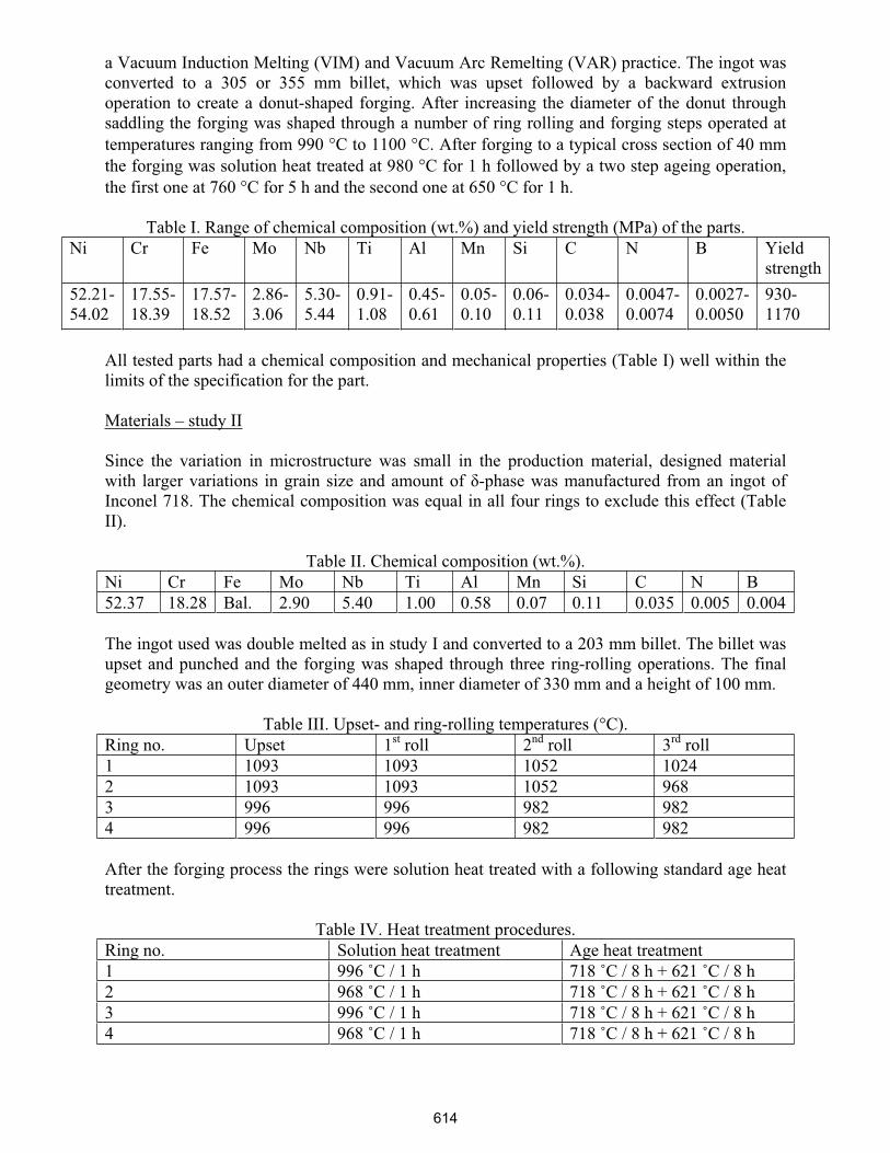
Figure 1. Sketch showing the cross section of the low pressure turbine case. The tool wear on
tools from hook 2, hook 3 and the outer contour were measured.
A sketch of the cross section of the low pressure turbine case can be seen in figure 1. Both
ceramic and carbide tools are used when machining the case. In this study, tools from 90 cases
were evaluated and only cemented carbide tool inserts (figure 2a) from the machining of the
outer contour and two hooks were selected. Tool wear is easier to quantify on a carbide tool than
on a ceramic tool. In production, the largest change of machinability was experienced when
grooving the hooks.
615
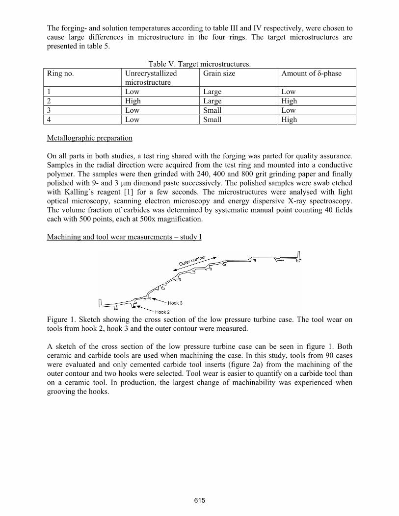
(a) (b)
Figure 2 (a) The three cemented carbide tools studied. (b) Tool used for machining hook 3. The
flank wear is shown as the narrow worn field at the top of the tool. The height of this field is the
flank wear measurement.
Production parameters such as cutting speed, feed and cutting time were held constant during the
whole test series. The height of the flank wear on the tools was measured in a light microscope at
30x magnification (figure 2b). This flank wear was correlated to the chemical composition of the
work piece recorded with X-ray spectroscopy as presented in the material certificate from the
raw material supplier. In addition, data as hardness, microstructure and tensile strength from the
test rings were used.
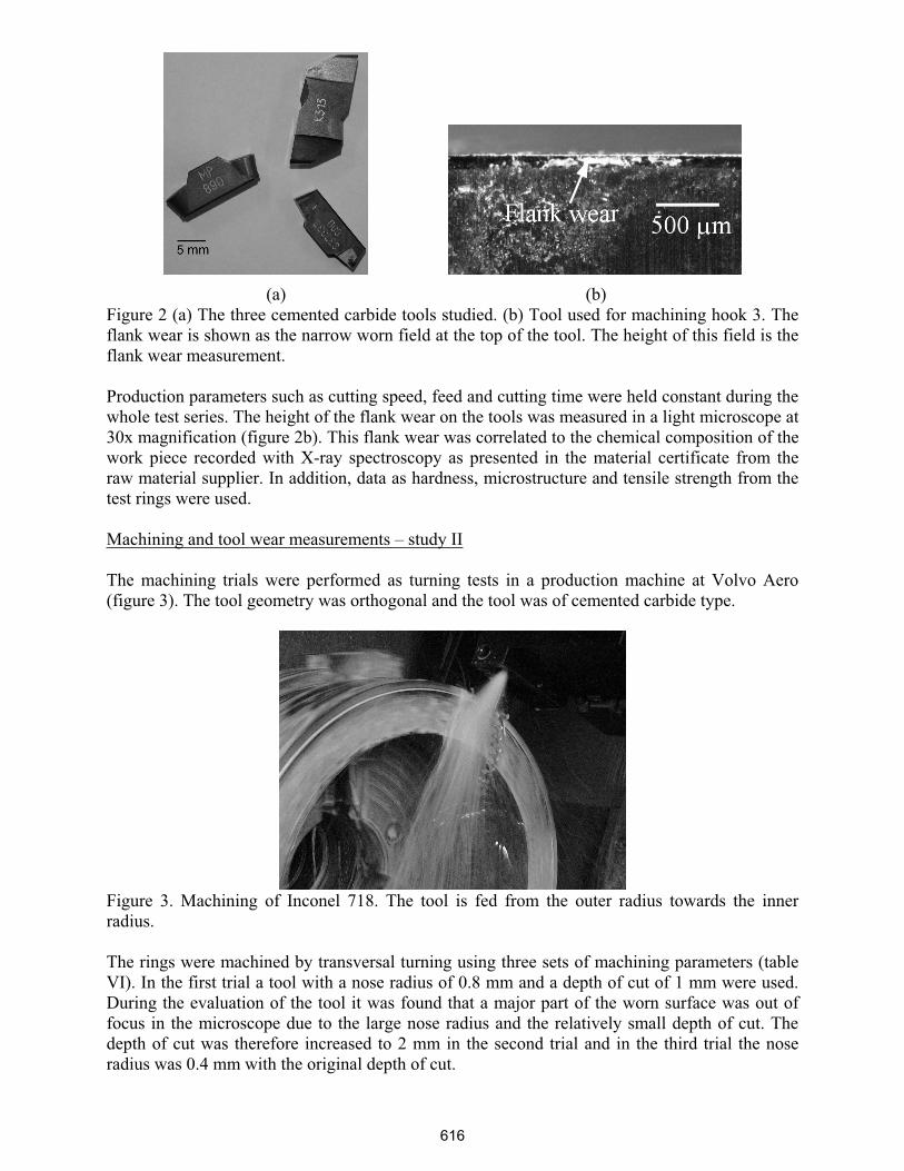
Machining and tool wear measurements – study II
The machining trials were performed as turning tests in a production machine at Volvo Aero
(figure 3). The tool geometry was orthogonal and the tool was of cemented carbide type.
Figure 3. Machining of Inconel 718. The tool is fed from the outer radius towards the inner
radius.
The rings were machined by transversal turning using three sets of machining parameters (table
VI). In the first trial a tool with a nose radius of 0.8 mm and a depth of cut of 1 mm were used.
During the evaluation of the tool it was found that a major part of the worn surface was out of
focus in the microscope due to the large nose radius and the relatively small depth of cut. The
depth of cut was therefore increased to 2 mm in the second trial and in the third trial the nose
radius was 0.4 mm with the original depth of cut.
616
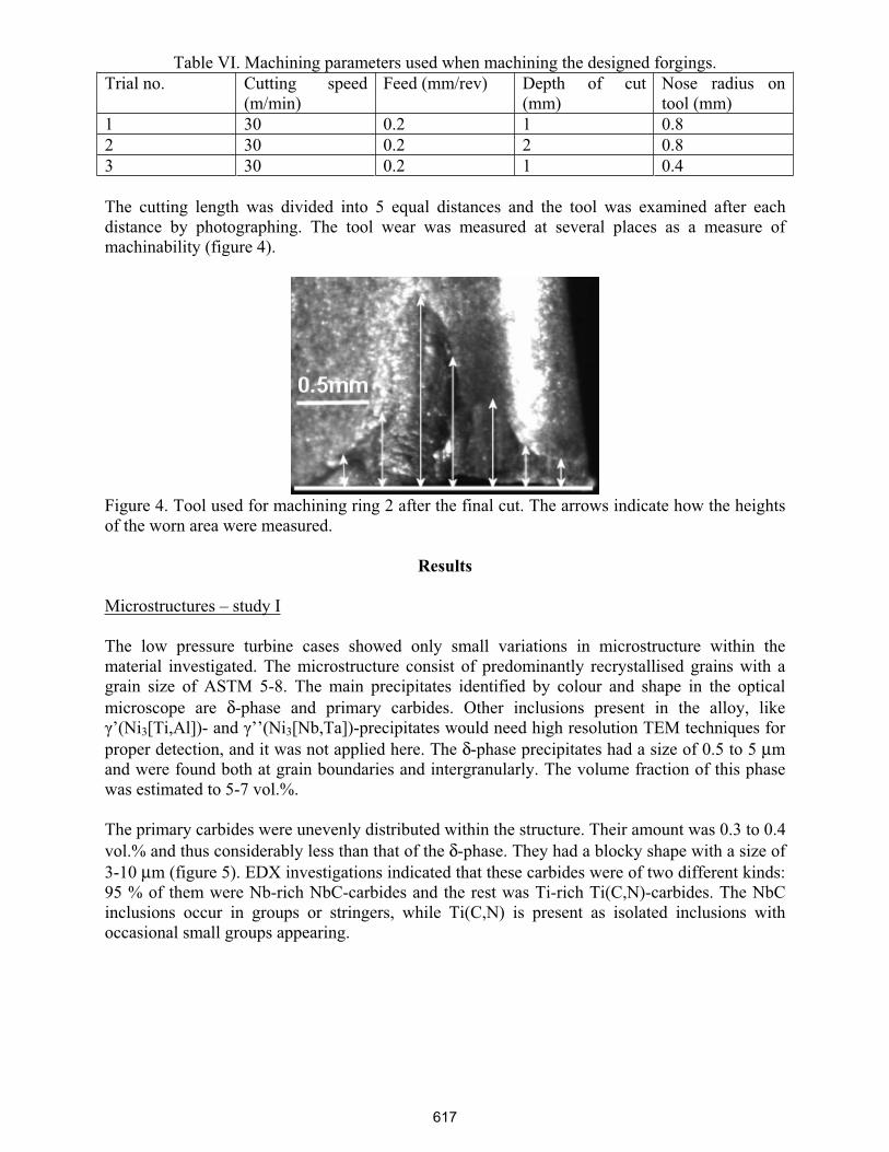
Table VI. Machining parameters used when machining the designed forgings.
Trial no. Cutting speed
(m/min)
Feed (mm/rev) Depth of cut
(mm)
Nose radius on
tool (mm)
1 30 0.2 1 0.8
2 30 0.2 2 0.8
3 30 0.2 1 0.4
The cutting length was divided into 5 equal distances and the tool was examined after each
distance by photographing. The tool wear was measured at several places as a measure of
machinability (figure 4).
Figure 4. Tool used for machining ring 2 after the final cut. The arrows indicate how the heights
of the worn area were measured.
Results
Microstructures – study I
The low pressure turbine cases showed only small variations in microstructure within the
material investigated. The microstructure consist of predominantly recrystallised grains with a
grain size of ASTM 5-8. The main precipitates identified by colour and shape in the optical
microscope are δ-phase and primary carbides. Other inclusions present in the alloy, like
’(Ni3[Ti,Al])- and ’’(Ni3[Nb,Ta])-precipitates would need high resolution TEM techniques for
proper detection, and it was not applied here. The δ-phase precipitates had a size of 0.5 to 5 µm
and were found both at grain boundaries and intergranularly. The volume fraction of this phase
was estimated to 5-7 vol.%.
The primary carbides were unevenly distributed within the structure. Their amount was 0.3 to 0.4
vol.% and thus considerably less than that of the δ-phase. They had a blocky shape with a size of
3-10 µm (figure 5). EDX investigations indicated that these carbides were of two different kinds:
95 % of them were Nb-rich NbC-carbides and the rest was Ti-rich Ti(C,N)-carbides. The NbC
inclusions occur in groups or stringers, while Ti(C,N) is present as isolated inclusions with
occasional small groups appearing.
617
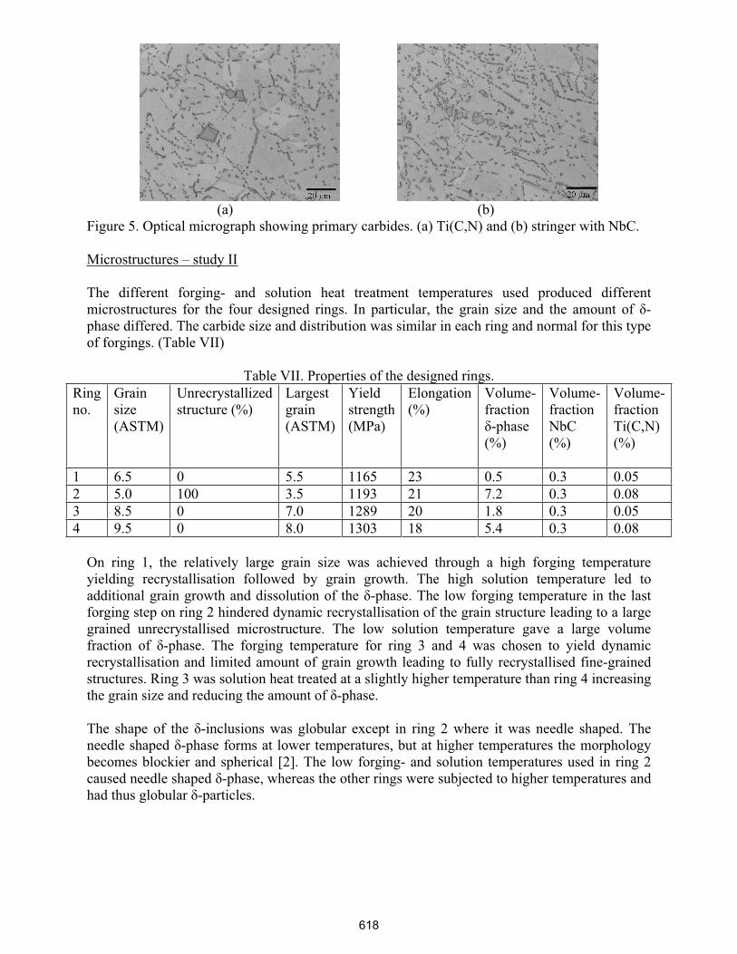
(a) (b)
Figure 5. Optical micrograph showing primary carbides. (a) Ti(C,N) and (b) stringer with NbC.
Microstructures – study II
The different forging- and solution heat treatment temperatures used produced different
microstructures for the four designed rings. In particular, the grain size and the amount of -
phase differed. The carbide size and distribution was similar in each ring and normal for this type
of forgings. (Table VII)
Table VII. Properties of the designed rings.
Ring
no.
Grain
size
(ASTM)
Unrecrystallized
structure (%)
Largest
grain
(ASTM)
Yield
strength
(MPa)
Elongation
(%)
Volume-
fraction
-phase
(%)
Volume-
fraction
NbC
(%)
Volume-
fraction
Ti(C,N)
(%)
1 6.5 0 5.5 1165 23 0.5 0.3 0.05
2 5.0 100 3.5 1193 21 7.2 0.3 0.08
3 8.5 0 7.0 1289 20 1.8 0.3 0.05
4 9.5 0 8.0 1303 18 5.4 0.3 0.08
On ring 1, the relatively large grain size was achieved through a high forging temperature
yielding recrystallisation followed by grain growth. The high solution temperature led to
additional grain growth and dissolution of the -phase. The low forging temperature in the last
forging step on ring 2 hindered dynamic recrystallisation of the grain structure leading to a large
grained unrecrystallised microstructure. The low solution temperature gave a large volume
fraction of -phase. The forging temperature for ring 3 and 4 was chosen to yield dynamic
recrystallisation and limited amount of grain growth leading to fully recrystallised fine-grained
structures. Ring 3 was solution heat treated at a slightly higher temperature than ring 4 increasing
the grain size and reducing the amount of -phase.
The shape of the -inclusions was globular except in ring 2 where it was needle shaped. The
needle shaped -phase forms at lower temperatures, but at higher temperatures the morphology
becomes blockier and spherical [2]. The low forging- and solution temperatures used in ring 2
caused needle shaped -phase, whereas the other rings were subjected to higher temperatures and
had thus globular -particles.
618
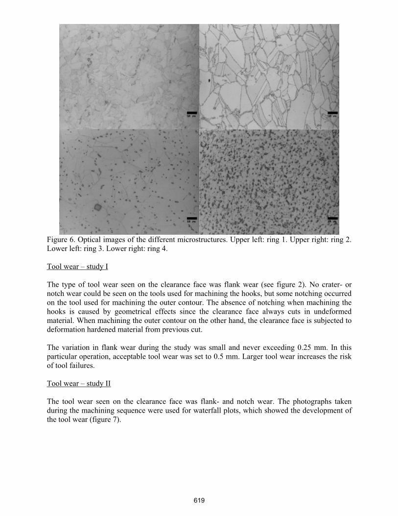
Figure 6. Optical images of the different microstructures. Upper left: ring 1. Upper right: ring 2.
Lower left: ring 3. Lower right: ring 4.
Tool wear – study I
The type of tool wear seen on the clearance face was flank wear (see figure 2). No crater- or
notch wear could be seen on the tools used for machining the hooks, but some notching occurred
on the tool used for machining the outer contour. The absence of notching when machining the
hooks is caused by geometrical effects since the clearance face always cuts in undeformed
material. When machining the outer contour on the other hand, the clearance face is subjected to
deformation hardened material from previous cut.
The variation in flank wear during the study was small and never exceeding 0.25 mm. In this
particular operation, acceptable tool wear was set to 0.5 mm. Larger tool wear increases the risk
of tool failures.
Tool wear – study II
The tool wear seen on the clearance face was flank- and notch wear. The photographs taken
during the machining sequence were used for waterfall plots, which showed the development of
the tool wear (figure 7).
619
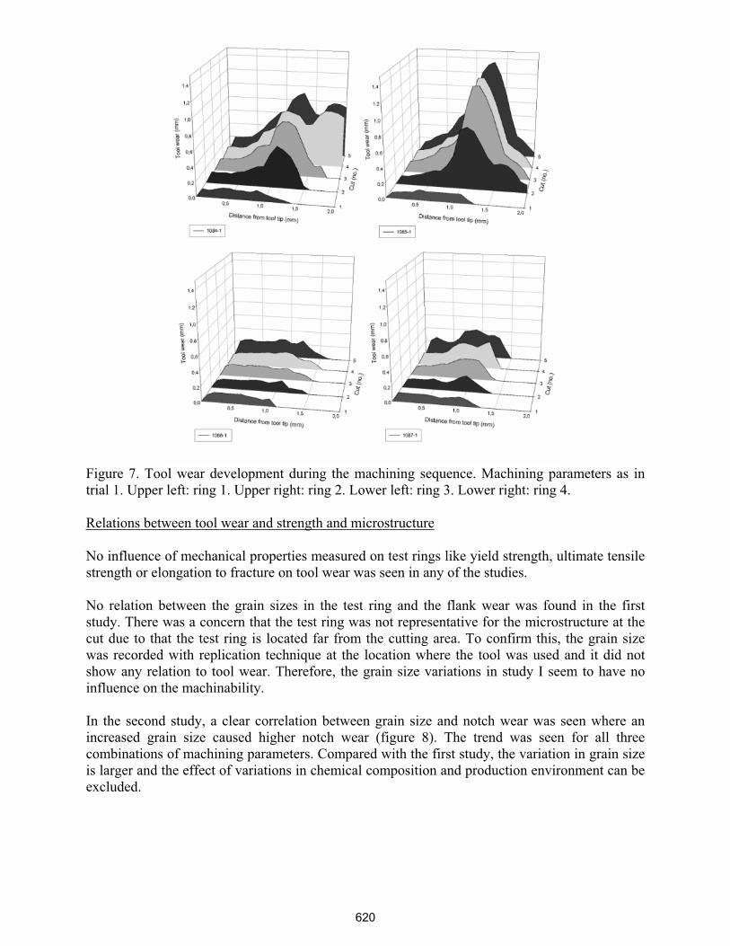
Figure 7. Tool wear development during the machining sequence. Machining parameters as in
trial 1. Upper left: ring 1. Upper right: ring 2. Lower left: ring 3. Lower right: ring 4.
Relations between tool wear and strength and microstructure
No influence of mechanical properties measured on test rings like yield strength, ultimate tensile
strength or elongation to fracture on tool wear was seen in any of the studies.
No relation between the grain sizes in the test ring and the flank wear was found in the first
study. There was a concern that the test ring was not representative for the microstructure at the
cut due to that the test ring is located far from the cutting area. To confirm this, the grain size
was recorded with replication technique at the location where the tool was used and it did not
show any relation to tool wear. Therefore, the grain size variations in study I seem to have no
influence on the machinability.
In the second study, a clear correlation between grain size and notch wear was seen where an
increased grain size caused higher notch wear (figure 8). The trend was seen for all three
combinations of machining parameters. Compared with the first study, the variation in grain size
is larger and the effect of variations in chemical composition and production environment can be
excluded.
620
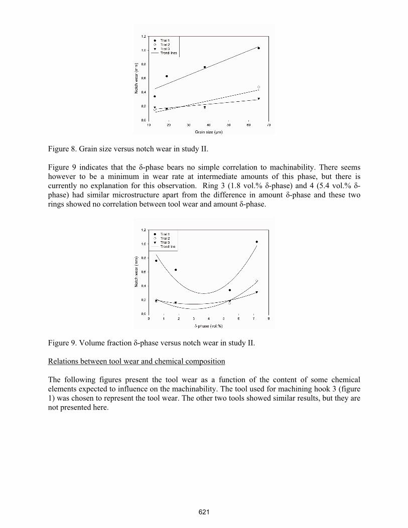
Figure 8. Grain size versus notch wear in study II.
Figure 9 indicates that the -phase bears no simple correlation to machinability. There seems
however to be a minimum in wear rate at intermediate amounts of this phase, but there is
currently no explanation for this observation. Ring 3 (1.8 vol.% -phase) and 4 (5.4 vol.% -
phase) had similar microstructure apart from the difference in amount -phase and these two
rings showed no correlation between tool wear and amount -phase.
Figure 9. Volume fraction -phase versus notch wear in study II.
Relations between tool wear and chemical composition
The following figures present the tool wear as a function of the content of some chemical
elements expected to influence on the machinability. The tool used for machining hook 3 (figure
1) was chosen to represent the tool wear. The other two tools showed similar results, but they are
not presented here.
621
(a) (b)
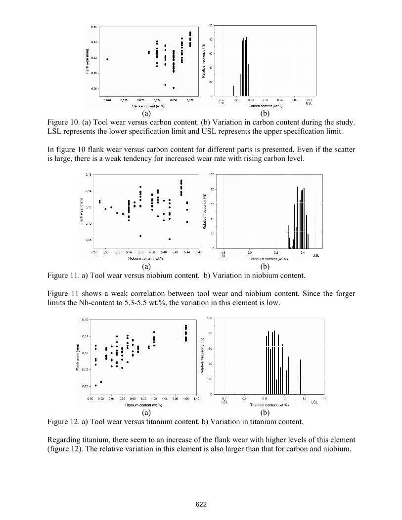
Figure 10. (a) Tool wear versus carbon content. (b) Variation in carbon content during the study.
LSL represents the lower specification limit and USL represents the upper specification limit.
In figure 10 flank wear versus carbon content for different parts is presented. Even if the scatter
is large, there is a weak tendency for increased wear rate with rising carbon level.
(a) (b)
Figure 11. a) Tool wear versus niobium content. b) Variation in niobium content.
Figure 11 shows a weak correlation between tool wear and niobium content. Since the forger
limits the Nb-content to 5.3-5.5 wt.%, the variation in this element is low.
(a) (b)
Figure 12. a) Tool wear versus titanium content. b) Variation in titanium content.
Regarding titanium, there seem to an increase of the flank wear with higher levels of this element
(figure 12). The relative variation in this element is also larger than that for carbon and niobium.
622
Discussion
Machining
The flank wear in the operations studied in production was low and stable. The machining
parameters were chosen so that premature tool breakage was unlikely to occur, which is
considered positive from a production point of view. This is particularly important in the final
machining of the low pressure turbine case where scrapping a part is very costly. The operations
were run to a flank wear between 0.08 and 0.15 mm, which is considered small. This creates a
buffer for variations in materials and processes which always occurs in a production
environment. During the designed experiments however, it was possible to use a machining
sequence producing larger tool wear. This resulted in easier analysis of tools and a clearer
detection of machinability differences.
Factors influencing the machinability
A low variation in material properties is beneficial for robust manufacturing processes. During
the first production study, the variation in chemical composition and microstructure of the
production material has been small.
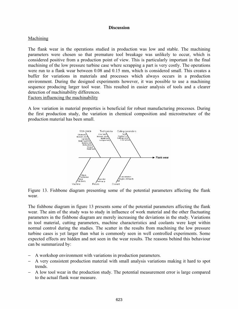
Figure 13. Fishbone diagram presenting some of the potential parameters affecting the flank
wear.
The fishbone diagram in figure 13 presents some of the potential parameters affecting the flank
wear. The aim of the study was to study in influence of work material and the other fluctuating
parameters in the fishbone diagram are merely increasing the deviations in the study. Variations
in tool material, cutting parameters, machine characteristics and coolants were kept within
normal control during the studies. The scatter in the results from machining the low pressure
turbine cases is yet larger than what is commonly seen in well controlled experiments. Some
expected effects are hidden and not seen in the wear results. The reasons behind this behaviour
can be summarized by:
− A workshop environment with variations in production parameters.
− A very consistent production material with small analysis variations making it hard to spot
trends.
− A low tool wear in the production study. The potential measurement error is large compared
to the actual flank wear measure.
623
Material behaviour during machining
The nickel based superalloys is a material group with poor machinability. The good mechanical
properties sustained at high temperatures, its ability to work harden and its hard abrasive
particles cause high temperatures and high stresses in the cutting zone [3]. Literature reports
different types of wear mechanisms depending on cutting parameters and type of tool material. A
common view is that a built-up edge forms due to extreme strain conditions. High temperatures
in combination with high local shear and compressive stresses might also cause destruction of
the cutting edge [4]. The description of tool wear is complicated and the tool wear mechanisms
on the flank- and rake face might be different and influence each other [5].
Focke et al. concluded that the main tool wear mechanism when machining Inconel 718 using
cemented carbide tools is abrasion wear [5]. Hard particles like carbides in the work material
cause abrasion on the tool. Like other studies, the tool wear measurements confirmed the
hypothesis that carbide forming elements affect the machinability [6]. Titanium and niobium in
Inconel 718 form primary carbides that are abrasive and bulky precipitates. TiC has a melting
point at 3200 °C and a hardness of 2200 HV [7] at room temperature. They undergo no major
phase transformations up to their melting point and are therefore some of the most stable
compounds existing. They are formed during solidification and are due to their properties not
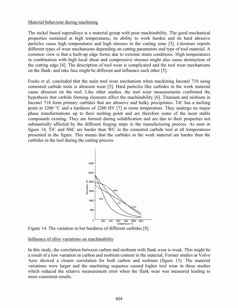
substantially affected by the different forging steps in the manufacturing process. As seen in
figure 14, TiC and NbC are harder than WC in the cemented carbide tool at all temperatures
presented in the figure. This means that the carbides in the work material are harder than the
carbides in the tool during the cutting process.
Figure 14. The variation in hot hardness of different carbides [8].
Influence of alloy variations on machinability
In this study, the correlation between carbon and niobium with flank wear is weak. This might be
a result of a low variation in carbon and niobium content in the material. Former studies at Volvo
Aero showed a clearer correlation for both carbon and niobium (figure 15). The material
variations were larger and the machining sequence caused higher tool wear in these studies
which reduced the relative measurement error when the flank wear was measured leading to
more consistent results.
624
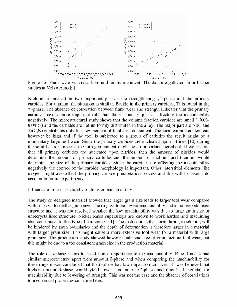
Figure 15. Flank wear versus carbon- and niobium content. The data are gathered from former
studies at Volvo Aero [9].
Niobium is present in two important phases, the strengthening ’’-phase and the primary
carbides. For titanium the situation is similar. Beside in the primary carbides, Ti is found in the
’-phase. The absence of correlation between flank wear and strength indicates that the primary
carbides have a more important role than the ’’- and ’-phases, affecting the machinability
negatively. The microstructural study shows that the volume fraction carbides are small (~0.03-
0.04 %) and the carbides are not uniformly distributed in the alloy. The major part are NbC and
Ti(C,N) contributes only to a few percent of total carbide content. The local carbide content can
however be high and if the tool is subjected to a group of carbides the result might be a
momentary large tool wear. Since the primary carbides are nucleated upon nitrides [10] during
the solidification process, the nitrogen content might be an important ingredient. If we assume
that all primary carbides are nucleated upon nitrides, then the amount of nitrides would
determine the amount of primary carbides and the amount of niobium and titanium would
determine the size of the primary carbides. Since the carbides are affecting the machinability
negatively the control of the carbide morphology is important. Other interstitial elements like
oxygen might also affect the primary carbide precipitation process and this will be taken into
account in future experiments.
Influence of microstructural variations on machinability
The study on designed material showed that larger grain size leads to larger tool wear compared
with rings with smaller grain size. The ring with the lowest machinability had an unrecrystallised
structure and it was not resolved weather the low machinability was due to large grain size or
unrecrystallised structure. Nickel based superalloys are known to work harden and machining
also contributes to this type of hardening [11]. The dislocations that form during machining will
be hindered by grain boundaries and the depth of deformation is therefore larger in a material
with larger grain size. This might cause a more extensive tool wear for a material with large
grain size. The production study showed however independence of grain size on tool wear, but
this might be due to a too consistent grain size in the production material.
The role of -phase seems to be of minor importance to the machinability. Ring 3 and 4 had
similar microstructure apart from amount -phase and when comparing the machinability for
these rings it was concluded that the -phase has low impact on tool wear. It was believed that
higher amount -phase would yield lower amount of ’’-phase and thus be beneficial for
machinability due to lowering of strength. This was not the case and the absence of correlations
to mechanical properties confirmed this.
625
Future work
The study shows indications of factors influencing the machinability of Inconel 718. There are
however some scatter due to variations in the production environment and low variations in the
chemical composition. In order to isolate the influence of chemical composition, experiments on
designed material with variations in chemical composition and constant microstructure needs to
be performed. There is also an interest in machinability tests on partly recrystallised structures,
where mix of large and small grains is obtained.
Conclusions
The machinability of forged Inconel 718 was studied. The main conclusions of the study are:
• Niobium, carbon and titanium are important elements affecting the machinability. These
elements are present in the primary carbides that are decreasing the machinability by
causing abrasive wear.
• Larger grain size causes a decrease in machinability due to larger depth of deformation.
• In fully heat treated Inconel 718, the strength is of minor importance to the machinability
in the range tested.
Acknowledgements
Financial support was given by the Graduate school in Materials Science at Chalmers University
of Technology. Carlton Forge Works and Carpenter are greatly acknowledged for providing
material and knowledge in production processes. Co-operation with Dr. Göran Sjöberg, Mr.
Anders Wretland and Mr. Frank Skystedt at Volvo Aero Corporation and Dr. Peter Sotkovszki at
Chalmers University of Technology are acknowledged.
References
1. Kathleen Mills et al., eds., Metals handbook, vol. 9 (Metals Park, OH: American society for
metals, 1985), 308.
2. Matthew J. Donachie and Stephen J. Donachie, Superalloys: a technical guide, (Materials
Park, OH: ASM International, 2002), 105-106.
3. I.A. Choudhury, M.A. El-Baradie, “Machinability of nickel-base super alloys: a general
review”, Journal of Materials Processing Technology, 77 (1998), 278-284
4. Edward M. Trent and Paul K. Wright, Metal Cutting, (Woburn, MA: Butterworth –
Heinemann, 2000), 301
5. A.E. Focke, F.E. Westermann, J. Kemphaus, W.T. Shih, M. Hoch, “Wear of superhard
materials when cutting superalloys”, Wear, 46 (1978), 65-79
6. J.J. Schirra, D.V. Viens, “Metallurgical factors influencing the machinability of Inconel 718”,
Superalloys 718, 625, 706 and various derivates. ed. E.A. Loria. (Warrendale, PA: The Minerals,
Metals & Materials Society, 1994), 827-838
626
7. Edward M. Trent and Paul K. Wright, Metal Cutting, (Woburn, MA: Butterworth –
Heinemann, 2000), 177
8. Edward M. Trent and Paul K. Wright, Metal Cutting, (Woburn, MA: Butterworth –
Heinemann, 2000), 178
9. Viktor Recina and Frank Skystedt, (Report 9653-752, Volvo Aero Corporation, 2000).
10. A. Mitchell, A.J. Schmalz, C. Schvezov, S.L. Cockcroft, “The precipitation of primary
carbides in alloy 718”, Superalloys 718, 625, 706 and various derivates. ed. E.A. Loria.
(Warrendale, PA: The Minerals, Metals & Materials Society, 1994), 65-78
11. Matthew J. Donachie and Stephen J. Donachie, Superalloys: a technical guide, (Materials
Park, OH: ASM International, 2002), 190.
627


![INFLUENCE OF MATERIAL PROPERTIES ON THE MACHINABILITY IN FACE MILLING …mit.imt.si/Revija/izvodi/mit126/sekulic.pdf · m. sekuli] et al.: influence of material properties on the](https://img.pdfslide.net/doc/110x75/5c9f4f8e88c9935f2d8d2963/influence-of-material-properties-on-the-machinability-in-face-milling-mitimtsirevijaizvodimit126.jpg)