Embed Size (px)
Citation preview

Originator: Philip Stacey,
Senior Project Manager,
Materials Testing
Approved by: Bob Pemble,
Executive Director,
Civil Construction
Approved for Intranet Publication:
4 November 2013
Controlled Document Number:
QM 0182
Version Number:
V0.1
Review by:
20 September 2014
Document uncontrolled when printed. Check DCI Intranet for controlled document. Page 1 of 129
Printed on 21/02/2014
MATERIALS TESTING MANUAL

2 | P a g e
CONTENTS
SECTIONS
SECTION 1 - CODES OF PRACTICE
SECTION 2 - SAMPLING AND TESTING SOILS
SECTION 3 - SAMPLING AND TESTING AGGREGATE
SECTION 4 - SAMPLING AND TESTING PAVEMENT MARKING AND
TRAFFIC CONTROL DEVICES
SECTION 5 - SAMPLING AND TESTING BITUMEN AND RELATED PRODUCTS
SECTION 6 - SAMPLING AND TESTING CEMENT AND CONCRETE
SECTION 7 - PAVEMENT TESTING
SECTION 8 - AUSTRALIAN STANDARDS AND OTHER PUBLICATIONS COVERED
UNDER THE DEPARTMENT OF PLANNING AND INFRASTRUCTURE
ROADWORKS SPECIFICATION
SECTION 9 - NOT USED
SECTION 10 - NOT USED

INDEX OF CODES OF PRACTICE
METHOD NO. SECTION 1 – METHOD CODE OF PRACTICE PAGE NUMBER
NTCP 101.1
NTCP 102.1
NTCP 103.1
NTCP 105.2
NTCP 106.1
NTCP 107.1
Selection of Test Methods
Testing Field Compaction for Conformance
Site Selection by the Stratified Random Technique
Audit Testing of Compaction - Joint Method
Registration of Asphalt Mix Designs
Ride Quality
2
3
11
16
18
22

4 | P a g e
CODE OF PRACTICE NTTP 101.1
SELECTION OF TEST METHODS
1. SCOPE
This Code covers the selection of the most appropriate test method for sampling or testing of
materials.
The Northern Territory Department of Infrastructure Test Methods (NTTM) and Codes of Practice
(NTCP) have been developed to clearly identify the practice to be adopted.
2. SELECTION OF TEST METHOD
The Department of Infrastructure Test Methods and Codes of Practice contained in this Materials
Testing manual shall take precedence over all test methods and procedures, and shall be used in
conjunction with relevant Australian Standards.
Where tests are required which are not included in the manual, the appropriate Australian Standard
method shall be used. In special circumstances where tests are required which are not covered in
this manual or by Australian Standards, other appropriate methods may be used at the
Superintendent's approval, i.e.
Australian Road Research Board (ARRB)
Austroads (Austroads)
National Association of Australian
State Road Authorities (NAASRA)
British Standards Institution (BSI)
American Society for Testing Materials ASTM (ASTM)

5 | P a g e
CODE OF PRACTICE NTTP 102.1
TESTING FIELD COMPACTION FOR CONFORMANCE
1. SCOPE
This Code sets down the procedures to be followed when carrying out acceptance testing of field
compaction of pavement materials, earthworks and backfill.
This Code takes precedence over Australian Standards.
For work being carried out under contract, this Code must be read in conjunction with the particular
contract specification and relevant test methods.
2. LOT TESTING
2.1 Test Lot Bounds
Test lot bounds shall be determined by the contractor in accordance with the specification.
Areas within 150mm of the edges of construction, or within 5 metres of lateral construction
joints should be excluded from the lot.
Soils and pavement materials which do not appear essentially homogenous and are not
uniform in terms of maximum size and particle size distribution may be included in the lot
provided that laboratory compaction tests are performed on material from each field density
test site ie one for one testing.
2.2 Selection of a Lot
It is the responsibility of the Superintendent or, on quality system contracts, the contractor, to
define the bounds of the lot, to designate any areas to be excluded from the lot on the basis
of appearance or test-rolling response and to nominate any areas, excluded under Section
2.1 which is required to be assessed separately.
2.3 Selection of Test Sites within a Lot
The validity of lot testing depends on there being no bias associated with the selection of test
sites. Prior to the start of the selection process, every point in the lot must have an equal
chance of being selected.
The method for selecting the test sites is covered in NTCP 103.1 - Site Selection by the
Stratified Random Technique.
3. FIELD DENSITY MEASUREMENT
Different methods shall not be used in the determination of field densities within a lot.
The following test methods are currently applicable:

6 | P a g e
CODE OF PRACTICE NTTP 102.1
3.1 Test Methods
Department of Infrastructure Test Methods and Codes of Practice.
Australian Standard Test Methods:
AS1289.2.1.1 - Determination of the Moisture Content of a Soil - Oven Drying
Method;
AS1289.5.2.1 - Determination of the Dry Density Moisture Content – Relation of a
Soil Using Modified Compactive Effort;
AS1289.5.4.1 - Dry Density Ratio, Moisture Ratio and Moisture Variation;
AS1289.5.4.2 - Assignment of Maximum Dry Density and Optimum Moisture
Content Values;
AS1289.5.8.1 - Determination of Field Moisture Content and Field Dry Density of a
Soil – Method Using a Nuclear Surface Moisture - Density Gauge -
Direct Transmission Mode;
AS 1289.5.8.4 - Nuclear Surface Moisture – Density Gauges – Calibration Using
Standards Blocks.
The job specification must be checked to see whether or not acceptance is based on testing
of the work in lots.
3.2 Selection of Test Methods
Nuclear gauges shall be used for the determination of field density. When environmental
conditions are such that the results from the nuclear gauge could be affected, at the
superintendent's approval alternative methods may be considered.
Whenever practicable, the same method shall be used for all field density testing carried out
on a given material on any one project.
Results from different modes of operation are not comparable.
3.3 Nuclear Gauge Testing
For earthworks and pavement materials, nuclear gauge testing shall be performed in
accordance with AS 1289.5.8.1.
3.4 Depth of Testing
The depth over which density testing is carried out by Nuclear Gauge in the direct
transmission mode, shall be with the probe set at a point equal to, or as near as practicable
to the nominal layer thickness.
NOTE: Should the probe be inserted to a depth greater than the nominal layer thickness the
test must be repeated. This can be checked when collecting samples for moisture
contents for processing by AS1289.2.1.1.
7 | P a g e
CODE OF PRACTICE NTTP 102.1
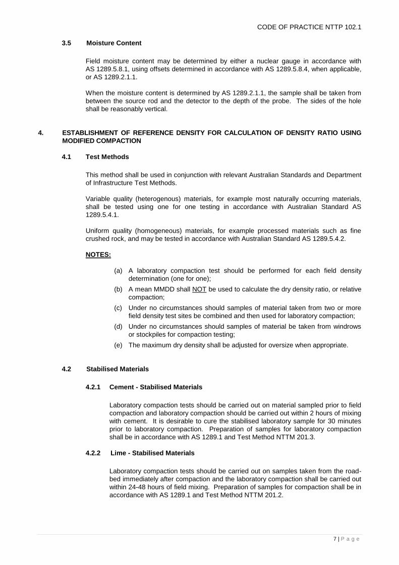
3.5 Moisture Content
Field moisture content may be determined by either a nuclear gauge in accordance with
AS 1289.5.8.1, using offsets determined in accordance with AS 1289.5.8.4, when applicable,
or AS 1289.2.1.1.
When the moisture content is determined by AS 1289.2.1.1, the sample shall be taken from
between the source rod and the detector to the depth of the probe. The sides of the hole
shall be reasonably vertical.
4. ESTABLISHMENT OF REFERENCE DENSITY FOR CALCULATION OF DENSITY RATIO USING
MODIFIED COMPACTION
4.1 Test Methods
This method shall be used in conjunction with relevant Australian Standards and Department
of Infrastructure Test Methods.
Variable quality (heterogenous) materials, for example most naturally occurring materials,
shall be tested using one for one testing in accordance with Australian Standard AS
1289.5.4.1.
Uniform quality (homogeneous) materials, for example processed materials such as fine
crushed rock, and may be tested in accordance with Australian Standard AS 1289.5.4.2.
NOTES:
(a) A laboratory compaction test should be performed for each field density
determination (one for one);
(b) A mean MMDD shall NOT be used to calculate the dry density ratio, or relative
compaction;
(c) Under no circumstances should samples of material taken from two or more
field density test sites be combined and then used for laboratory compaction;
(d) Under no circumstances should samples of material be taken from windrows
or stockpiles for compaction testing;
(e) The maximum dry density shall be adjusted for oversize when appropriate.
4.2 Stabilised Materials
4.2.1 Cement - Stabilised Materials
Laboratory compaction tests should be carried out on material sampled prior to field
compaction and laboratory compaction should be carried out within 2 hours of mixing
with cement. It is desirable to cure the stabilised laboratory sample for 30 minutes
prior to laboratory compaction. Preparation of samples for laboratory compaction
shall be in accordance with AS 1289.1 and Test Method NTTM 201.3.
4.2.2 Lime - Stabilised Materials
Laboratory compaction tests should be carried out on samples taken from the road-
bed immediately after compaction and the laboratory compaction shall be carried out
within 24-48 hours of field mixing. Preparation of samples for compaction shall be in
accordance with AS 1289.1 and Test Method NTTM 201.2.

8 | P a g e
CODE OF PRACTICE NTTP 102.1
5. OVERSIZE MATERIAL
Oversize material is defined as any material which is coarser than the maximum size allowed in the
laboratory compaction test AS1289.5.2.1. The mould size for laboratory compaction test is
determined based on the oversize materials present in the moisture content sample. Determine the
oversize correction in accordance with AS1289.5.4.1.
6. CALCULATION OF MEAN AND CHARACTERISTIC VALUES OF DENSITY RATIO IN LOT
TESTING
A minimum of 3 tests shall apply to any lot submitted for testing. Two methods are available for
calculation of the Dry Density Ratio for determining the conformance of a lot. The method to be
selected is based on the number of tests within a lot.
3-5 tests; Determine the Mean Dry Density Ratio in accordance with section 6.1
6 or more tests; Determine the Characteristic Mean Dry Density Ratio in accordance with section
6.2.
All test results from a lot must be included in the calculations, including those markedly
different from the average.
6.1 The Mean Dry Density (R)
Is calculated as follows:
R = sum of xi
n
Where R = mean dry density ratio for the lot,
xi = an individual test result, and
n = the number of results in the lot.
When less than 6 tests are used to determine compliance of a lot, the Mean Dry Density
Ratio only is used.
6.2 The Characteristic Mean Dry Density Ratio (RC)
Firstly calculate the standard deviation and the mean of the sample. Then determine if there
are any outliers. An outlier is any density ratio result which is more than 2.5 standard
deviations away from the mean. All outliers shall be removed from the calculation of the
characteristic mean dry density ratio.
All results including means and standard deviations shall be recalculated after removing any
outliers. The procedure for removing outliers shall then be rechecked as above.
If after removing any outliers the number of tests involved is reduced to less than 6, the Dry
Density Ratio shall be determined in accordance with the Mean Dry Density Ratio
specification requirements, and not the Characteristic Mean Dry Density Ratio
specification.

9 | P a g e
CODE OF PRACTICE NTTP 102.1
The Standard Deviation/s is defined as the Distribution of the Dry Density Ratio of a lot,
calculated as follows:
s = [sum of (xi - R)2 divided by (n - 1)]
0.5
Where xi = an individual test result,
R = the mean of n results, and
n = the number of test results in the lot.
Rc is then calculated as follows:
Rc = R - ks
Where Rc = the characteristic mean dry density ratio for the lot,
k = the multiplier in Table 1, and
s = the standard deviation.
7. RETESTING OF WORK
7.1 Retesting of a Lot
Retesting should only be undertaken after reworking or corrective action and not merely on
the basis of the test results. When retesting is carried out, then the Superintendent shall be
informed.
Values of Maximum Dry Density and Optimum Moisture Content shall be determined again
for each field density as the material has been reworked.
7.2 Repeat Testing to Recheck a Result
Repeat testing should be undertaken only if an error is known or suspected to have occurred
in the testing procedures, or if an outlier has been identified. A replacement result can be
obtained by random selection of a test site within the relevant stratum of the lot. If the
volume of retesting is greater than one test or one stratum, discard all testing and obtain a
new set of random numbers and retest the entire lot.
Any stratum within a lot which has not been included in the assessment of Characteristic
Mean Dry Density Ratio for any reason shall be identified as a separate lot and tested
independently.
8. SPECIFICATIONS NOT BASED ON LOT TESTING
Some job specifications may simply stipulate that the material on specific areas, which do not
constitute part of a lot, must be compacted to not less than a certain percentage of density ratio
based on modified compactive effort. In these cases the Superintendent must be consulted as to the
number of test sites required and to the manner in which they are to be located.
9. REPORTING
Compaction test reports shall contain;
i) All test results from a lot including:
- Those markedly different from the means, Outliers, Retests, and;
- Repeat tests due to sampling or testing errors;
ii) All compaction curve graphs when requested, and;

10 | P a g e
CODE OF PRACTICE NTTP 102.1
iii) Copies of the stratified random selection worksheet used for selection of test site locations;
iv) Mean dry density ratio or characteristic mean dry density ratio as appropriate.
FLOWCHART
DETERMINATION OF LABORATORY COMPACTION METHOD
NOTE: When necessary, recombine the material passing the 37.5mm sieve and that
passing the 19mm sieve and thoroughly mix.

11 | P a g e
CODE OF PRACTICE NTTP 102.1
TABLE 1
VALUES OF THE MULTIPLIER k FOR CHARACTERISTIC MEAN DRY DENSITY RATIO (RC)
Number of test per lot
(n) k
6 0.50
7 0.54
8 0.56
9 0.59
10 0.61
15 0.68
20 0.72
PAVEMENT CONFORMANCE CRITERIA
E X A M P L E O N L Y
The following examples demonstrate the application of pavement conformance criteria.
Xi = an individual test result
R = mean of n results
n = number of tests
k = multiplier
s = standard deviation
R = Sum of Xi
n
Rc = R – ks
s = [Sum of (Xi - R)2 divided by (n-1)] 0.5
WHEN SIX (6) OR MORE, TESTS ARE USED TO DETERMINE COMPLIANCE OF A LOT
EXAMPLE 1A
n Xi
1 100.1% R = 599.1% R = 99.85%
2 99.6% 6
3 101.1% s = 0.734166
k = 0.5 (for six tests)
4 99.1% Rc= 99.85% - (0.5 x 0.734166)
5 100.0%
6 99.2% Rc=99.48% Rc = 99.5% (rounded to 0.1%)
-----------
Sum 599.1%

12 | P a g e
CODE OF PRACTICE NTTP 102.1
EXAMPLE 1B
n Xi
1 100.1%
2 97.2%
3 102.4% R = 802.3 R = 100.29
4 101.1% 8
5 103.1% s = 1.9372
6 98.8% k = 0.56 (for eight tests)
7 100.5%
8 99.1% Rc=100.29% - (0.56 x 1.9372)
---------- Rc= 99.20% Rc = 99.2% (rounded to 0.1%)
Sum 802.3%
Compliance/rejection will be judged on current Department specifications. An example is included in
Table 2 Column B.
NOTE: The effect of the standard deviation on the mean density ratio is as follows. Small standard
deviations will have small effects. Large standard deviations will have a significant effect.
WHEN LESS THAN SIX (6) TESTS ARE USED TO DETERMINE COMPLIANCE OF A LOT
EXAMPLE 2A
n Xi R = Sum of Xi
1 100.1% n
2 99.2%
3 101.1% R = 499.5%
4 99.1% 5
5 100.0% R = 99.9% R = 99.9% (rounded to 0.1%)
----------
Sum 499.5%
Compliance/rejection will be judged on current Department specifications. An example is attached in
Table 2 Column A.

13 | P a g e
CODE OF PRACTICE NTTP 103.1
SITE SELECTION BY THE STRATIFIED RANDOM TECHNIQUE
1. SCOPE
This Code sets out the procedure to be followed in selecting sites of a 2-dimensional lot by a stratified
random technique. Stratified random sampling consists of stratifying the lot into subdivisions and
then randomly selecting a sample from each subdivision.
2. PROCEDURE
(a) Determine the width, length and area of the lot;
(b) Determine the number of test samples required in the lot in accordance with the specification.
Divide the lot into sub-lots (stratum) of approximately equal areas, such that there is one sub-lot
for each test sample required;
(c) Number the strata as Strata 1, Strata 2, Strata 3 etc;
(d) Place the point of a pencil or other marker blindly on the page of random numbers. (See Sheet
5);
(e) Select a starting point from the first digit (after the decimal) of this number as our column
number, and the second and third digits as our row numbers;
Example: Starting Point = 0.271 (Selected blindly)
Column = 2
Row = 71
(f) Select the first random number by going to the column and row selected above;
Example: Column 2, row 71, random number = 0.846. This will be used to determine our (y)
coordinate for site 1 in stratum 1;
(g) Two random numbers from Table of Random Numbers are required to locate each test site
within each stratum. So select the second random number by proceeding vertically down the
column to the next number and select this as our second random number for site 1 in stratum 1
Example: (0.750) this will be used to determine our (x) coordinate;
(h) Let the y coordinate of the area be the chainage or length of the stratum and let the x coordinate
of the area be the width or offset from the left hand side;
(i) The chainage for site one will be at (0.846 multiplied by the length of the stratum) = y (stratum 1)
Example: 0.846 x 125m = 105.8m (The Y Coordinate chainage should be rounded to 0.1m);
(j) The offset from the left hand side for site one will be at (0.750 multiplied by the width of the
stratum) = x (stratum 1).
Example: x = 0.750 x 8m = 6.0m (The X Coordinate chainage should be rounded to 0.1m);
(k) Select further random numbers by proceeding vertically down the column and if necessary to the
top of the next column until as many numbers as required are obtained;

14 | P a g e
CODE OF PRACTICE NTCP 103.1
(l) The chainage for site two will be at (0.317) multiplied by the length of the stratum) = y (site 2).
Example: y = 0.317 x 125m = 39.6m;
(m) The offset from the left hand side for site 2 will be (0.403) multiplied by the length of the stratum)
= y (site 2).
Example: x = 0.403 x 8m = 3.2m offset;
(n) Add the lengths of all proceeding stratas to the y co-ordinate chainage to produce a running
chainage.
Example: (39.6 + 125)
Running chainage = 164.6m;
(o) Project chainages may also be added if required.
Example: 164.6m or 0.1646km + (project chainage) = _____ kms
0.1646km + 13.24km = 13.405kms.
NOTES ON TEST:
1. Random sampling does not imply haphazard sampling but requires a detailed
predetermined sampling plan which eliminates bias.
2. Random numbers may be selected by a variety of appropriate techniques. The method
detailed here shall take precedence.
3. When selecting subsequent series of random numbers it is possible that the same series
may occur more than once. When this is the outcome in successive lots, the second
series of random numbers should be discarded and a further series of numbers selected.
4. When conducting retesting of a lot, a new series of random numbers shall be selected.
5. If in selecting a series of random numbers by running vertically down the column, the
bottom right hand corner of the table is reached, continue selecting numbers from the top
left hand corner of the page.
6. Retesting is only appropriate if there has been a mistake in sampling or test procedure or
if the result is obviously impossible. If the volume of retesting is greater than one stratum,
all testing for the lot shall be discarded and a new set of random numbers obtained and
the entire lot retested.
7. Apart from retesting for the reason indicated in Note 6, there is no statistical justification
for retesting a stratum or part of a lot which fails.
3. REPORT
Report as per attached worksheet.
15 | P a g e
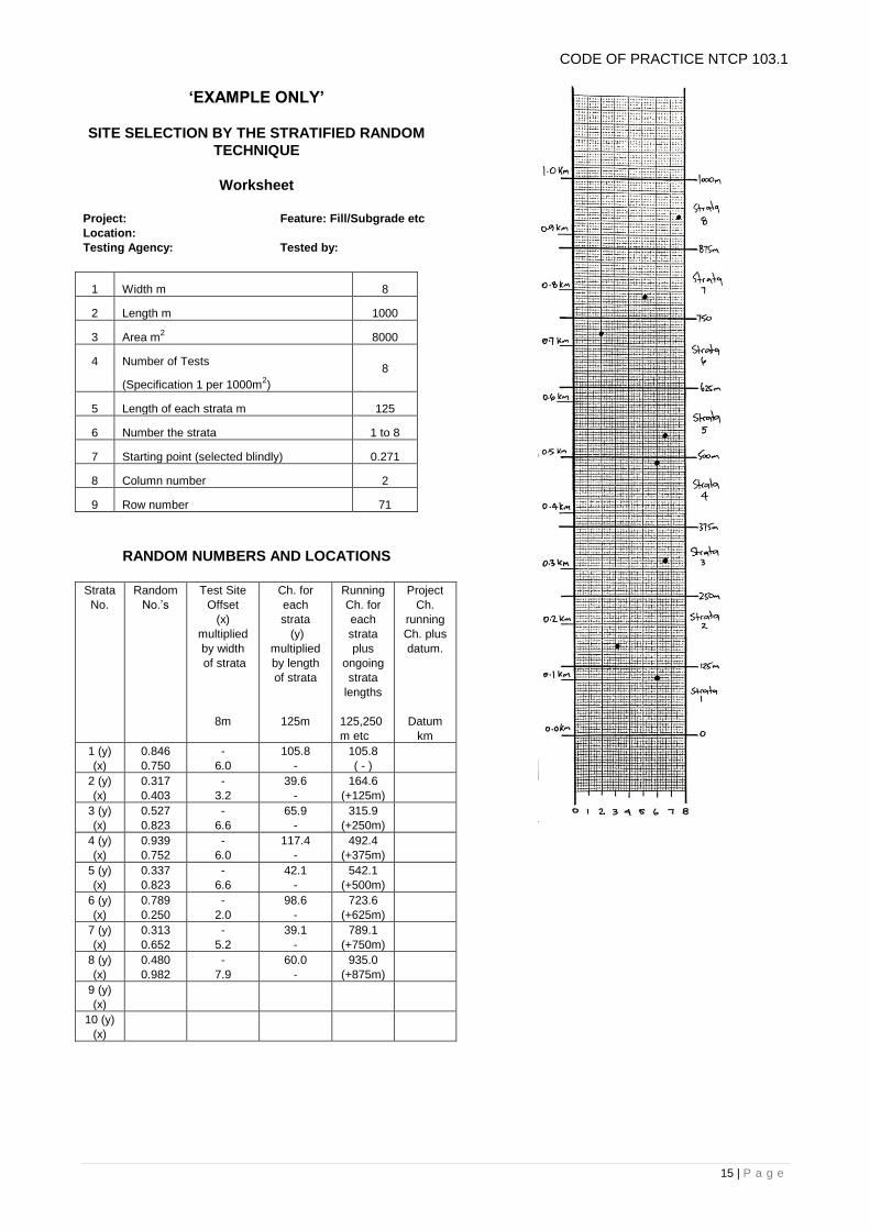
‘EXAMPLE ONLY’
SITE SELECTION BY THE STRATIFIED RANDOM
TECHNIQUE
Worksheet
Project: Feature: Fill/Subgrade etc
Location:
Testing Agency: Tested by:
1 Width m 8
2 Length m 1000
3 Area m2 8000
4 Number of Tests
(Specification 1 per 1000m2)
8
5 Length of each strata m 125
6 Number the strata 1 to 8
7 Starting point (selected blindly) 0.271
8 Column number 2
9 Row number 71
RANDOM NUMBERS AND LOCATIONS
Strata
No.
Random
No.’s
Test Site
Offset
(x)
multiplied
by width
of strata
8m
Ch. for
each
strata
(y)
multiplied
by length
of strata
125m
Running
Ch. for
each
strata
plus
ongoing
strata
lengths
125,250
m etc
Project
Ch.
running
Ch. plus
datum.
Datum
km
1 (y)
(x)
0.846
0.750
-
6.0
105.8
-
105.8
( - )
2 (y)
(x)
0.317
0.403
-
3.2
39.6
-
164.6
(+125m)
3 (y)
(x)
0.527
0.823
-
6.6
65.9
-
315.9
(+250m)
4 (y)
(x)
0.939
0.752
-
6.0
117.4
-
492.4
(+375m)
5 (y)
(x)
0.337
0.823
-
6.6
42.1
-
542.1
(+500m)
6 (y)
(x)
0.789
0.250
-
2.0
98.6
-
723.6
(+625m)
7 (y)
(x)
0.313
0.652
-
5.2
39.1
-
789.1
(+750m)
8 (y)
(x)
0.480
0.982
-
7.9
60.0
-
935.0
(+875m)
9 (y)
(x)
10 (y)
(x)
CODE OF PRACTICE NTCP 103.1

16 | P a g e
CODE OF PRACTICE NTCP 103.1
SITE SELECTION BY THE STRATIFIED RANDOM
TECHNIQUE
Worksheet
Project: Feature: Fill/Subgrade etc
Location:
Testing Agency: Tested by:
1 Width m
2 Length m
3 Area m2
4 Number of Tests
5 Length of each strata m
6 Number the strata
7 Starting point (selected blindly)
8 Column number
9 Row number
RANDOM NUMBERS AND LOCATIONS
Strata
No.
Random
No.’s
Test Site
Offset
(x)
multiplied
by width
of strata
……m
Ch. for
each
strata
(y)
multiplied
by length
of strata
……m
Running
Ch. for
each
strata
plus
ongoing
strata
lengths
……m
Project
Ch.
running
Ch. plus
datum.
Datum
km
1 (y)
(x)
2 (y)
(x)
3 (y)
(x)
4 (y)
(x)
5 (y)
(x)
6 (y)
(x)
7 (y)
(x)
8 (y)
(x)
9 (y)
(x)
10 (y)
(x)

17 | P a g e
CODE OF PRACTICE: NTCP 103.1
RANDOM NUMBER TABLE
0 1 2 3 4 5 6 7 8 9
0 0.092 0.734 0.817 0.945 0.406 0.535 0.447 0.541 0.990 0.424
1 0.821 0.096 0.524 0.619 0.121 0.225 0.974 0.939 0.802 0.840
2 0.637 0.840 0.584 0.609 0.783 0.801 0.391 0.965 0.988 0.303
3 0.108 0.592 0.764 0.089 0.472 0.895 0.556 0.941 0.961 0.394
4 0.726 0.694 0.011 0.528 0.600 0.693 0.418 0.832 0.175 0.431
5 0.252 0.951 0.583 0.565 0.146 0.472 0.912 0.044 0.290 0.030
6 0.457 0.565 0.971 0.660 0.021 0.071 0.024 0.875 0.336 0.511
7 0.009 0.418 0.218 0.590 0.479 0.180 0.536 0.712 0.179 0.228
8 0.589 0.845 0.507 0.438 0.997 0.530 0.095 0.680 0.687 0.738
9 0.856 0.031 0.071 0.813 0.319 0.999 0.017 0.201 0.626 0.194
10 0.694 0.200 0.005 0.452 0.894 0.441 0.090 0.853 0.927 0.312
11 0.907 0.620 0.668 0.064 0.892 0.346 0.873 0.801 0.767 0.553
12 0.332 0.070 0.625 0.007 0.974 0.291 0.075 0.798 0.503 0.721
13 0.775 0.632 0.673 0.186 0.209 0.300 0.777 0.293 0.050 0.820
14 0.463 0.348 0.945 0.179 0.458 0.689 0.077 0.189 0.301 0.662
15 0.341 0.383 0.668 0.946 0.476 0.462 0.402 0.466 0.004 0.216
16 0.820 0.594 0.311 0.436 0.407 0.861 0.723 0.740 0.481 0.911
17 0.912 0.819 0.928 0.894 0.481 0.050 0.599 0.041 0.074 0.947
18 0.462 0.617 0.843 0.430 0.106 0.990 0.634 0.370 0.686 0.020
19 0.718 0.380 0.904 0.497 0.420 0.323 0.126 0.840 0.493 0.514
20 0.218 0.780 0.570 0.060 0.200 0.244 0.548 0.342 0.322 0.158
21 0.238 0.072 0.632 0.389 0.140 0.922 0.654 0.547 0.665 0.176
22 0.251 0.855 0.669 0.384 0.286 0.829 0.628 0.479 0.154 0.953
23 0.308 0.335 0.789 0.102 0.264 0.220 0.251 0.908 0.020 0.136
24 0.456 0.797 0.271 0.484 0.183 0.919 0.945 0.055 0.911 0.677
25 0.481 0.790 0.616 0.093 0.156 0.292 0.090 0.707 0.808 0.557
26 0.906 0.252 0.802 0.884 0.594 0.799 0.577 0.446 0.145 0.617
27 0.619 0.480 0.421 0.436 0.215 0.572 0.577 0.367 0.811 0.996
28 0.073 0.164 0.335 0.593 0.391 0.073 0.319 0.139 0.032 0.967
29 0.176 0.681 0.893 0.005 0.453 0.812 0.622 0.512 0.434 0.352
30 0.041 0.319 0.906 0.392 0.231 0.268 0.458 0.191 0.371 0.110
31 0.139 0.879 0.926 0.505 0.826 0.435 0.284 0.352 0.144 0.925
32 0.425 0.163 0.290 0.441 0.720 0.701 0.582 0.738 0.458 0.600
33 0.107 0.022 0.193 0.183 0.289 0.858 0.495 0.209 0.732 0.670
34 0.217 0.748 0.172 0.807 0.852 0.921 0.896 0.634 0.094 0.709
35 0.461 0.621 0.173 0.569 0.054 0.898 0.084 0.047 0.352 0.249
36 0.281 0.139 0.209 0.009 0.946 0.595 0.019 0.832 0.414 0.890
37 0.110 0.801 0.859 0.096 0.995 0.853 0.828 0.347 0.831 0.977
38 0.713 0.140 0.940 0.167 0.775 0.176 0.715 0.581 0.777 0.968
39 0.774 0.902 0.863 0.928 0.698 0.334 0.741 0.159 0.190 0.238
40 0.784 0.663 0.013 0.848 0.137 0.188 0.540 0.056 0.421 0.440
41 0.262 0.719 0.130 0.858 0.099 0.469 0.323 0.695 0.862 0.489
42 0.685 0.608 0.698 0.221 0.570 0.482 0.875 0.487 0.112 0.701
43 0.740 0.968 0.995 0.597 0.202 0.544 0.983 0.279 0.581 0.427
44 0.794 0.575 0.160 0.585 0.424 0.297 0.298 0.405 0.504 0.555
45 0.432 0.087 0.787 0.330 0.822 0.702 0.362 0.034 0.386 0.426
46 0.686 0.263 0.451 0.885 0.029 0.483 0.784 0.090 0.422 0.841
47 0.735 0.945 0.705 0.845 0.844 0.767 0.771 0.109 0.741 0.821
48 0.598 0.905 0.700 0.310 0.156 0.717 0.685 0.805 0.791 0.537
49 0.221 0.579 0.185 0.106 0.949 0.816 0.464 0.827 0.208 0.155
50 0.575 0.565 0.465 0.555 0.503 0.062 0.974 0.928 0.439 0.165
51 0.475 0.530 0.479 0.611 0.291 0.564 0.958 0.569 0.670 0.963
52 0.007 0.664 0.710 0.843 0.424 0.711 0.704 0.561 0.470 0.855
53 0.268 0.878 0.655 0.361 0.075 0.174 0.133 0.758 0.555 0.198
54 0.789 0.555 0.391 0.316 0.614 0.260 0.168 0.720 0.455 0.904
55 0.006 0.576 0.748 0.804 0.532 0.582 0.312 0.776 0.029 0.888
56 0.812 0.513 0.102 0.865 0.969 0.358 0.715 0.686 0.132 0.182
57 0.935 0.177 0.278 0.587 0.226 0.930 0.064 0.156 0.641 0.120
58 0.000 0.961 0.762 0.013 0.350 0.067 0.706 0.630 0.852 0.219
59 0.080 0.532 0.847 0.464 0.191 0.193 0.920 0.903 0.378 0.944
60 0.632 0.303 0.807 0.933 0.455 0.789 0.556 0.093 0.485 0.321
61 0.364 0.575 0.042 0.197 0.853 0.611 0.742 0.280 0.596 0.290
62 0.140 0.177 0.859 0.198 0.528 0.091 0.359 0.407 0.001 0.562
63 0.901 0.771 0.359 0.808 0.206 0.002 0.964 0.905 0.807 0.493
64 0.125 0.498 0.333 0.363 0.122 0.288 0.039 0.677 0.446 0.991
65 0.911 0.333 0.366 0.005 0.209 0.560 0.400 0.496 0.777 0.520
66 0.801 0.120 0.963 0.957 0.631 0.103 0.511 0.390 0.541 0.900
67 0.242 0.790 0.827 0.148 0.889 0.233 0.875 0.127 0.921 0.486
68 0.577 0.464 0.701 0.998 0.814 0.277 0.820 0.260 0.603 0.498
69 0.955 0.013 0.002 0.581 0.090 0.262 0.361 0.313 0.447 0.572
70 0.017 0.959 0.974 0.609 0.027 0.450 0.716 0.400 0.032 0.828
71 0.946 0.282 0.846 0.683 0.362 0.995 0.862 0.785 0.223 0.909
72 0.870 0.637 0.750 0.839 0.382 0.167 0.648 0.415 0.057 0.280
73 0.081 0.491 0.317 0.483 0.954 0.546 0.755 0.302 0.842 0.551
74 0.414 0.722 0.403 0.277 0.556 0.353 0.633 0.501 0.981 0.542
75 0.794 0.088 0.527 0.169 0.363 0.416 0.809 0.320 0.850 0.111
76 0.817 0.569 0.823 0.558 0.460 0.092 0.982 0.165 0.634 0.321
77 0.640 0.839 0.939 0.361 0.426 0.654 0.603 0.893 0.597 0.162
78 0.737 0.777 0.752 0.343 0.496 0.072 0.336 0.633 0.247 0.699
79 0.751 0.017 0.337 0.459 0.427 0.654 0.556 0.627 0.699 0.999
80 0.883 0.843 0.823 0.888 0.617 0.512 0.993 0.561 0.480 0.445
81 0.680 0.093 0.789 0.939 0.161 0.194 0.291 0.039 0.557 0.848
82 0.754 0.182 0.250 0.767 0.904 0.950 0.993 0.129 0.813 0.146
83 0.589 0.551 0.313 0.922 0.453 0.787 0.553 0.165 0.923 0.118
84 0.270 0.867 0.652 0.879 0.888 0.696 0.927 0.126 0.020 0.486
85 0.259 0.885 0.480 0.869 0.090 0.966 0.400 0.761 0.963 0.801
86 0.529 0.925 0.982 0.289 0.329 0.332 0.932 0.099 0.944 0.526
87 0.883 0.413 0.653 0.738 0.628 0.571 0.882 0.934 0.801 0.594
88 0.384 0.544 0.014 0.041 0.671 0.073 0.859 0.184 0.300 0.329
89 0.122 0.956 0.099 0.462 0.049 0.654 0.929 0.564 0.006 0.852
90 0.082 0.021 0.380 0.501 0.900 0.355 0.065 0.691 0.711 0.760
91 0.379 0.021 0.680 0.065 0.743 0.078 0.666 0.332 0.985 0.962
92 0.674 0.810 0.600 0.350 0.008 0.470 0.808 0.054 0.706 0.829
93 0.767 0.543 0.353 0.294 0.767 0.409 0.878 0.732 0.765 0.228
94 0.409 0.496 0.097 0.800 0.797 0.619 0.707 0.228 0.895 0.397
95 0.744 0.810 0.183 0.079 0.870 0.208 0.838 0.882 0.119 0.865
96 0.846 0.057 0.649 0.140 0.236 0.207 0.239 0.130 0.046 0.603
97 0.873 0.642 0.103 0.685 0.239 0.291 0.218 0.495 0.513 0.193
98 0.887 0.242 0.253 0.207 0.085 0.729 0.750 0.222 0.264 0.851
99 0.685 0.432 0.130 0.895 0.429 0.077 0.304 0.844 0.838 0.626

18 | P a g e
CODES OF PRACTICE: NTCP 105.2
JOINT AUDIT TESTING OF COMPACTION
1. SCOPE
This Code sets out the procedure which shall be followed when the Superintendent, as a result of a
dispute, elects to invite both parties jointly to audit a lot.
2. PURPOSE
To determine the conformance status of a lot, irrespective of all previous tests and audits.
3. PREPARATION
(a) Jointly select and agree on a time to conduct the joint audit;
(b) Jointly agree on the most appropriate facility, equipment and nuclear densometer to conduct
the joint-audit;
(c) Testing personnel from both parties shall be present during all phases of sampling and testing;
(d) The execution of all testing tasks shall be divided approximately equal between both parties.
4. METHOD
(e) Jointly determine the location of the tests using a stratified random technique in accordance
with NTCP 103.1.;
(f) Jointly check the nuclear densometer calibration status, gauge function checks and secondary
calibration;
(g) Jointly determine the standard counts on site in accordance with the manufacturer's handbook
and AS1289 5.8.1.;
(h) Jointly conduct the density testing in accordance with Department of Infrastructure and
Australian Standard requirements;
(i) From each site take samples for moisture content, and modified compaction determinations;
(j) At the completion of all field testing both parties shall return to the nominated facility to jointly
process the samples and test results and reports in accordance with Australian Standard
AS1289;
(k) Calculations shall be to the satisfaction of both parties;
(l) The results of these joint tests shall be used to determine the conformance status of the lot in
accordance with the specification requirements;
(m) At any time, and upon the request of either party the Superintendent and Contractor shall carry
out an evaluation of their respective testing methods to determine the reason for any
continuing discrepancies and arrive at a uniform testing technique.

19 | P a g e
CODES OF PRACTICE: NTCP 105.2
NOTES ON TEST:
1. Determine the moisture content in accordance with AS1289.2.1.1.;
2. Excavate the sample for the moisture content determination between the source rod and the
detector and to the depth of the source rod and ensure the sides of the hole are reasonably
vertical;
3. Ensure the sample for the modified compaction determination is taken beneath the gauge to the
depth of the source rod and ensure the sides of the hole are vertical;
4. Jointly record all readings and cross check recordings;
5. At the completion of field testing both parties shall initial all recordings;
6. Moisture content samples will be placed in the oven overnight;
7. Both parties shall have the option to keep a copy of the recordings overnight;
8. No one party shall proceed with the samples in the absence of the other party.
FLOW CHART FOR
JOINT AUDIT TESTING OF COMPACTION

20 | P a g e
CODE OF PRACTICE: NTCP 106.1
REGISTRATION OF ASPHALT MIX DESIGNS
1. INTRODUCTION
This Code of Practice describes the process for registration of asphalt mix designs for use in works
undertaken for the Department of Infrastructure (DoI).
Registration in accordance with the procedures in this Code of Practice does not guarantee the
handling and performance properties of this mix. Production, delivery, placement and compaction of
asphalt mixes shall comply with the relevant sections of the DoI Road works Master Specification and
any specific project requirements.
2. REGISTRATION
2.1 General
Applications to register an asphalt mix shall be submitted to The Department at least two
weeks prior to the proposed date of commencement of supply and shall be accompanied by
the information listed in Clause 2.2.
The registration of a mix design shall remain current for a period of 2 years subject to there
being no changes to the source or grading of aggregate components or the source and nature
of the binder. Registration may be extended beyond 2 years with the agreement of the
Department and the Superintendent of the project on which the mix is to be used.
2.2 Information Required
The following information shall be submitted for each new mix design:
a) Grading test results for each component;
b) Proportion of each component in the mix;
c) Grading of the mix;
d) Graphs of mix properties;
e) Supplier and class of binder and certificate of compliance;
f) Source of added filler and certificate of compliance for added filler;
g) Details of the type of additives, if any, and its proportion in the design mix;
h) Details of any proposed asphalt recycling including sieve analysis (after extraction of binder) and binder content of RAP;
i) Test information for all laboratory tests for the relevant mix type specified in Section 3;
j) Test information from production trial and modification of laboratory test data for identification as the “Job Mix”;
k) All the test results shall be current at the time of submission of the mix design;
l) All components of the asphalt mix shall comply with the DoI Road works Master Specification Section 9 – Dense Graded Asphalt.
2.3 Additional information required for Warm Mix Asphalt (WMA) Registration
a) WMA technology and/or WMA additives information including the classification and nominated proportions of additives;
b) WMA technology manufacturer's established target rate for water and additives and the acceptable variation for production;
c) Documentation that demonstrates proven field performance of the WMA technology for at least 2 years. Trials undertaken through Austroads and other State Authorities will be accepted.

21 | P a g e
CODE OF PRACTICE: NTCP 106.1
2.4 Notifications of Approval
Acceptance or rejection of applications for registration of asphalt mixes will be advised in writing. Additional information may be required by the department to complete the registration process.
Approved mixes will be issued with an identifying code.
Sufficient quantities of all components shall be provided for independent verification and assessment of the submitted mix design on request by the Department.
3. MIX DESIGN REQUIREMENTS
3.1 General
Mix design procedures and test methods shall follow the guidelines provided in Austroads
Guide to Pavement Technology Part 4B – Asphalt. Volumetric properties (Level 1 design) may
be determined using either Gyratory compaction (AS 2891.2.2) or Marshall compaction (AS
2891.5) of laboratory prepared or plant mixed specimens.
All testing shall be undertaken in a laboratory accredited by NATA for the relevant test
methods.
Table 1 - Traffic category and binder requirements for dense graded asphalt mix types
Traffic
Category Application Bitumen Type
Light Cycle Paths Class 320 or S10E
Medium Car Parks and Low Volume Traffic – less than 300 vld Class 320 or S10E
Heavy All Urban Roads and Intersections A15E
vld = vehicles per lane per day
3.2 Grading and binder content
The proportions of aggregate and binder in the mix and grading of aggregates including any
added filler, after mixing but before compaction, shall lie within the limits specified in Tables 3
and 4 for each size of and type of asphalt unless otherwise approved by the DoI.
Table 3 - Grading
Mix Type 1 2 3 4 5 6
Mix Size
(mm)
7 10 14 20 14
(A15E)
10 mm
(Car Park)
Sieve Size
AS (mm) Percentage passing sieve size (by mass)
26.5
19.0
13.2
9.5
6.7
4.75
2.36
1.18
0.60
0.30
0.15
0.075
100
85–100
70–87
44–65
29–48
19–35
12–25
8–16
5–8
100
90–100
70–90
58–76
40–58
27–44
17–35
11–24
7–16
4–7
100
85–100
70–85
62–75
53–70
35–52
24–40
15–30
10 –24
7–16
4–7
100
95–100
75–90
60–80
50–70
40–60
25–43
18–35
14–27
9–21
6–15
3–7
100
85 – 100
70 – 85
62 – 75
53 – 70
35 – 52
24 – 40
15 – 30
10 – 24
7 – 16
4– 7
100
90–100
68–87
50–76
32–57
22–42
15–31
10–23
6-–14
4–7
Total 100 100 100 100 100 100

22 | P a g e
CODE OF PRACTICE: NTCP 106.1
The grading curve shall be smooth and shall not vary from the outer one third of the range
between the specified limits for one sieve size to the opposite outer one third of the range
between the specified limits for an adjacent sieve size.
Table 4 - Binder content
Mix Type 1 2 3 4 5 6
Mix Size
(mm) 7 10 14 20
14
(A15E)
10 mm
(Car Park)
Binder
Content
(%by
mass)
5.0 – 7.0 4.5 – 6.5 4.6 – 6.5 4.0 - 6.0 4.8 – 6.5 4.5 – 6.5
3.3 Binder Film Index
Binder film index of all mix types shall be a minimum of 8.0 micron.
3.4 Volumetric test properties
a) Gyratory compaction
Mixes designed using gyratory compaction shall comply with the requirements of Table
5.
Table 5 - Compaction cycles and air voids for volumetric properties determined by gyratory
compaction
Mix Type 1 2 3 4 5 6
Mix Size
(mm)
7 10 14 20 14
(A15E)
10 mm
(Car Park)
Compaction
cycles Design air voids in laboratory compacted mix (%)
50 4.0 N/A N/A N/A N/A 4.0
80 4.0 N/A N/A N/A N/A
120 4.0 4.0 4.0 4.0 N/A
250 N/A >2.5 >2.5 >2.5 >2.5 N/A
Notes to Table 5
The design air voids values are approximate and may be adjusted to account for rounding of the binder content
value to the nearest 1.0%.
b) Marshall compaction
Mixes designed using Marshall compaction (50 blows) shall comply with the
requirements of Table 6.

23 | P a g e
CODE OF PRACTICE: NTCP 106.1
Table 6 - Marshall Properties and air voids for mixes designed using Marshall Compaction
Mix Type 1 2 3 4 5 6
Size (mm) 7 10 14 20 14 (A15E) 10
Design air voids 4.0 5.0 5.0 5.0 5.0 4.0
Stability (min)
(kN) 6.5 10 10 10 15 10
Flow (mm) 2–4 2–4 2–4 2–4 2–4 2–4
Notes to Table 5
The design air voids values are approximate and may be adjusted to account for rounding of the binder content value to
the nearest 1.0%.
3.5 Wheel Track Test Requirements
The maximum Tracking Depth tested under the Austroads Wheel tracking test method shall
not exceed the values for asphalt mixes specified in Table 7.
Table 7 - Maximum wheel tracking depth
Mix Type 1 2 3 4 5 6
Size (mm) 7 10 14 20 14 (A15E) 10
Traffic
category Maximum tracking depth at 60°C (mm)
Light traffic N/A N/A N/A N/A N/A N/A
Medium traffic N/A N/A N/A N/A N/A N/A
Heavy traffic N/A 3–6 3–6 3–6 1–3 N/A
Notes to Table 6
Wheel tracking test specimens shall be compacted to 5% air voids within a tolerance of 1% air voids. Total rut
depth is determined after 10,000 cycles.
3.6 Asphalt Mixes Containing Reclaimed Asphalt Pavement
Up to 15% of RAP may be incorporated in the design of Type 4 mixes subject to meeting the
design requirements as described Section 3.
4. PRODUCTION TRIAL AND JOB MIX DESIGN
A production trial shall be undertaken on the laboratory design mix to determine the Job Mix Design.
The production trial shall be used to verify the proportion of components, binder content, grading and
Marshall Properties of the asphalt mix meeting the mix design requirements specified in Section 3
and conforming with the tolerance on finished asphalt properties specified in the DoI Road works
Master Specification. Adjustments to the blend composition as a result of production trial shall be
designated the Job Mix Design.

24 | P a g e
CODE OF PRACTICE: NTCP 107.1
RIDE QUALITY
1. INTRODUCTION
This Code of Practice provides guidelines for the testing and acceptance of ride quality on asphalt
works undertaken for the Department of Infrastructure (DoI).
2. DEFINITIONS
2.1 Continuous Traffic Lane
A length of traffic lane which can be tested in a single test run uninterrupted by areas
exempted from ride quality assessment.
2.2 International Roughness Index (IRIqc)
The international measure of ride quality measured and recorded by in cumulative metres per
kilometre in each wheel path and averaged together. For the purposes of this Code of
Practice, roughness measurement is to be based on the IRIqc quarter car model.
Where required to convert between IRI and NAASRA counts/km, one NAASRA count in
counts/km/lane is approximately equivalent to an IRI of 0.04 m/km/lane. The more precise
conversion is given by the following formulae:
NAASRA Counts/km/lane = (26.49 x IRI) -1.27
or
IRI (m/km/lane) = (NAASRA Counts/km/lane + 1.27) / 26.49
2.3 Mean Lane Roughness Value
The mean of the Individual Lane Roughness Values within the lot as determined by the
appropriate test method.
2.4 Measuring Device
The device used for measurement of roughness shall be:
(a) Normal testing by DoI Rough-o-meter, calibrated to provide roughness counts converted
to IRI.
(b) In the event of non-compliance, The Contractor shall have the option of requesting
retest by ARRB Profile-o-meter. The cost of retesting will be allocated to the Contractor
unless the retesting shows compliance with the specified requirements, in which case
the cost of retesting will be paid by the Department.
3. LOT TESTING
All work shall be tested in lots of continuous traffic lane. A lot shall be defined as the length and width
of each continuous traffic lane constructed including any freeway ramps but excluding shoulders and
turn lanes. The maximum length of the lot shall be restricted to 2 km of continuous traffic lane.
The minimum length of the lot shall be the lesser of the total job length or 500 m.
Start and finish joints are to be excluded from testing.
Following areas may be excluded from ride quality testing or specified at a lower standard of ride
quality unless otherwise specified. Bridge decks, depending on the type of construction and number and type of expansion joints.
Small jobs (less than 300m in length) areas of limited access, roundabouts other very low
speed traffic locations.
Left lanes used as parking for most of the day or where the crown of an intersecting road
intrudes into the left lane.

25 | P a g e
CODE OF PRACTICE: NTCP 107.1
Pavement widening and part width reconstruction where the completed works is required to
match the profile of the adjacent existing pavement or required to match the ride quality of the
existing pavement.
Ride quality measurement shall be undertaken within three months after the application of the
surfacing.
4. RECTIFICATION
Where the Mean Lane Roughness Value of a lot is greater than the Mean Lane Roughness specified,
the work shall be rectified unless the Superintendent agrees to accept the work at a reduced
payment. Where the lot is to be rectified, the minimum length for any rectification work undertaken
shall be 100 m. Where the Superintendent agrees to accept the lot at a reduced payment, a
deduction to the contract sum shall be made in accordance with the provisions for MEASUREMENT
AND PAYMENT.
The Contractor shall bear the full cost of any necessary rectification work including the cost of any
additional work required to the underlying or adjacent pavement to comply with the ride quality
requirements of the specification. All rectification work shall be carried out in accordance with the
requirements of the specification.
A re-test of the lot shall be undertaken following completion of any rectification work.

26 | P a g e
INDEX OF TEST METHODS
TEST METHOD SECTION 2 - SAMPLING & TESTING SOILS PAGE NUMBER
NTTM 201.2
NTTM 201.3
NTTM 201.4
NTTM 202.2
NTTM 202.3
NTTM 203.1
NTTM 204.1
NTTM 204.5
NTTM 204.6
NTTM 204.7
NTTM 204.8
NTTM 205.1
NTTM 211.1
NTTM 215.1
NTTM 216.1
NTTM 217.1
Modified Compaction – Lime Stabilised Materials
Modified Compaction – Cement Stabilised Materials
Modified Compaction – Bituminous Stabilised Materials
California Bearing Ratio – Lime Stabilised Materials
California Bearing Ratio – Cement Stabilised Materials
Unconfined Compressive Strength
Cement Content of Stabilised Materials – Heat of
Neutralisation
Determination of the Lime Saturation Point of Stabilised
Materials – Ph Method
Available Calcium Oxide or Calcium Hydroxide in Lime
Rate of Spread of Lime or Cement
Stabiliser Distribution
Durability Cement Stabilised Materials
Plate Bearing Test
Standard Ball Penetration Test
Measurement of Layer Thickness
Particle Size Distribution – Oversize Material
2
5
7
10
13
15
21
24
27
30
31
32
36
39
41
43

27 | P a g e
TEST METHOD: NTTM 201.2
MODIFIED COMPACTION - LIME STABILISED MATERIALS
1. SCOPE
This test method sets out the procedures for determination of the relationship between Dry Density
and Moisture Content for mixtures of Materials and Lime stabilised in the field, or materials stabilised
in the laboratory.
This method is applicable to materials having no more than 20% retained on the 37.5mm AS sieve.
2. APPARATUS
As described in Australian Standard AS1289.5.2.1.
3. PREPARATION OF SAMPLE
Prepare the sample in accordance with the procedure prescribed in AS1289.2.1.1, AS1289.5.2.1 and
AS1289.5.4.1.
4. PROCEDURE
4.1 Stabilised in the Field
(a) The sample shall be taken within one hour from the time from the completion of
mixing in-situ;
(b) Immediately after the sample has been taken it shall be sealed in an airtight
container, sheltered, and transported as soon as practicable to the laboratory for
processing;
(c) The procedure is to be commenced immediately the sample is removed from the
airtight container;
(d) Prepare the specimen in accordance with AS1289.5.2.1 and AS1289.5.4.1;
(e) Cure the sample overnight;
(f) Compact the sample in accordance with AS1289.5.2.1;
(g) The compaction of the specimen is to be completed within 48 hours of delivery for
plant mixed material or, in the case of in-situ work, within 48 hours of the completion
of mixing.
4.2 Stabilised in the Laboratory
(a) Follow AS1289.5.2.1 Procedure (a) to (d) inclusive;
(b) Take one of the portions and determine the mass to the nearest 1g. Screen on a
4.75mm sieve. All material retained on the 4.75mm AS sieve shall be soaked for at
least one hour and then surface dried;
(c) Incorporate the prescribed additive as follows:
i. Hydrated Lime: Add the required amount of hydrated lime, calculated as a
percentage of the total dry mass of the portion as determined
in 4(b) to the material passing the 4.75mm AS sieve and
thoroughly mix the dry materials to a uniform colour.

28 | P a g e
TEST METHOD: NTTM 201.2
ii. Quicklime: Add the required amount of ground quicklime, calculated as a
percentage of the total dry mass of the portion determined in 4(b), to the
material passing the 4.75mm AS sieve and thoroughly and carefully mix
the dry materials to a uniform colour. Add a quantity of water equal to
one-half to two-thirds of the mass of quicklime added to the material.
Carefully mix, observing the safety precautions set out in Note 5.
Slaking will occur rapidly with the generation of heat. The magnitude of
the reaction will depend on the amount of quicklime present. Cover the
mixture and allow to stand for about 10 minutes. Remix to break up any
lumps that may have formed.
See Note 5 for safety precautions related to the use of quicklime.
(d) Add the required quantity of water to the mix. Select the quantities of water to be added so
that the soil optimum moisture content is straddled and the moisture steps are not excessive
for the soil type.
(e) Incorporate the saturated surface dry material retained on the 4.75mm sieve and remix.
(f) Repeat this procedure with the remaining portions of material.
(g) Place the mixture in a container and seal. Allow the mixture to cure overnight at room
temperature.
(h) Remix the material and adjust moisture if necessary.
(i) Compact the material in accordance with AS1289.5.2.1, procedure (g) to (q) inclusive.
5. CALCULATIONS
In accordance with AS1289.5.2.1 and AS1289.5.4.1.
6. REPORTING
In accordance with AS1289.5.2.1 and AS1289.5.4.1.
NOTES ON TEST:
1. Lime used in laboratory investigations should be the same type from the same source of
supply or manufacture as the lime proposed for use in the field. Unless otherwise specified or
approved, quicklime and hydrated line shall comply with Australian Standard 1672.1 – Limes
and Limestone – Limes for Building.
2. Hydrated lime is the most common form of lime used in lime stabilisation of road materials. It
is usually supplied in the form of a fine, white powder and consists essentially of calcium
hydroxide. No preparation is required.
3. Quicklime is supplied as ground quicklime, crushed or pebble quicklime or as lumps, and
consists essentially of calcium oxide. Unless supplied in ground form, the material should be
ground to pass a 2.36mm AS sieve and stored in an air-tight container and protected from
moisture until used.
4. Hydrated lime is relatively safe but care is required to protect the eyes when using hydrated
lime.

29 | P a g e
TEST METHOD: NTTM 201.2
5. Quicklime may be dangerous in the presence of moisture because of its highly caustic
nature. Even small amounts of perspiration on the skin may react with quicklime and
cause skin burns. Quicklime is especially dangerous to the eyes. Safety glasses, long-
sleeved coats and gloves should be worn, and protective cream applied to the hands
and arms as required, when using quicklime in the laboratory.

30 | P a g e
TEST METHOD: NTTM 201.4
MODIFIED COMPACTION - BITUMEN STABILISED MATERIALS
1. SCOPE
This test method sets out the procedures for the determination of the relationship between dry
density and moisture content for mixtures of soil, gravel or crushed rock material and bitumen, cut-
back bitumen, bitumen emulsion, or tar.
This method is applicable to materials with not more than 20% retained on the 37.5mm A.S. Sieve.
2. APPARATUS
As described as AS1289.5.2.1
3. PREPARATION OF SAMPLE
(a) Allow the sample to dry sufficiently to enable it to be crumbled. If necessary, dry the sample at
a temperature not exceeding 50OC;
(b) Break up any aggregations of particles in such a way as to avoid crushing any discrete
particles. All aggregations of particles are to be broken down so that if the sample was
screened on a 4.75mm A.S. sieve only discrete uncrushed particles would be retained. A
rubber pestle should be used to avoid breaking down sound pieces of mineral matter.
Adhering material should be brushed from coarse pieces. When in doubt as to whether lumps
are to be broken, place some in water and boil. If slaking occurs, the material should be
broken further with the rubber pestle;
(c) Prepare the sample and select the mould size in accordance with AS 1289.5.2.1 and AS
1289.5.4.1;
(d) Obtain by quartering or riffling six 3000g portions of the prepared sample.
4. BITUMINOUS MATERIALS
(a) Bituminous materials used in laboratory investigations should be of the same type and from the
same source of supply or manufacture as the materials proposed for use in the field. Unless
otherwise specified or approved the bituminous materials should comply with the requirements
of the appropriate Australian Standard (i.e. Bitumen, Cut Back Bitumen, Bitumen Emulsion, or
Tar);
(b) Where bitumen emulsion is specified or approved for use in investigations in relation to
stabilisation or modification of road materials, the water used in the test should be from the
same source as that proposed for use in the field.
5. ADDITION OF THE BITUMINOUS MATERIAL
( i ) DETERMINATION OF THE DESIRABLE VISCOSITY AND MOISTURE CONTENT FOR THE
ADDITION OF BITUMEN OR CUT BACK BITUMEN
(a) Take one of the 3000g portions of the sample obtained in 3 (d) and quarter or riffle it to obtain
6 to 8 portions, each about 300g;

31 | P a g e
TEST METHOD: NTTM 201.4
(b) Take one of the 300g portions of soil, add sufficient water to dampen the soil, mix thoroughly
and add a small quantity of bitumen that has been heated as necessary to produce a
"pourable" condition. Mix with a trowel in an attempt to produce a uniform mix. If the viscosity
is unsuitable for mixing, balls of unmixed bitumen will form. When this happens it is necessary
to cut back the bitumen with power kerosene starting from 5 per cent cutter and increasing by
2 per cent increments;
(c) To another 300g portion add a measured quantity of water (but do not exceed optimum
moisture content at this stage) and add a small amount of cut-back bitumen. Mix thoroughly
with a trowel and note ease (or difficulty) of mixing;
(d) Repeat procedures (b) and (c) with increases in moisture content of the soil and/or the
proportion of cutter in the bitumen until conditions for satisfactory mixing are determined;
(e) Record the moisture content of the soil and the cutter content of the bitumen at which
satisfactory mixing occurred;
(f) Adopt the soil moisture content and cutter content of the bitumen recorded in (e) in the
mixtures to be tested in accordance with this Test Method;
(g) Add the cut back bitumen to the moist soil in small quantities, mixing thoroughly after each
addition, until the required amount of bitumen has been added to the soil.
( ii ) DETERMINATION OF THE DESIRABLE VISCOSITY AND MOISTURE CONTENT FOR THE
ADDITION OF TAR
(a) Adopt a similar procedure to that described for bitumen above except that, instead of fluxing
with kerosene, different grades of tar should be used;
(b) Add the desired grade of tar to the moist soil in small quantities, mixing thoroughly after each
addition until the required amount of tar has been incorporated in the soil.
( iii ) ADDITION OF BITUMEN EMULSION
(a) Dampen the test portion to a moisture content of approximately 4% to 5%;
(b) Calculate the additional quantity of water to be added to bring the emulsion/soil mix to the
desired moisture content. For this purpose the water content of bitumen emulsion shall be
taken as 45 per cent by mass;
(c) Dilute the bitumen emulsion by adding at least half the additional water to the bitumen
emulsion. Add the remainder of the additional water to the soil portion;
(d) Add the diluted bitumen emulsion to the soil portion in small quantities mixing thoroughly after
each addition until the required amount of bitumen emulsion has been incorporated in the soil.
6. PROCEDURE
(a) Take one of the portions and determine the mass to the nearest 1g. Screen on a 4.75 mm A.S.
sieve. All material retained on the 4.75mm A.S. sieve shall be soaked for at least one hour
and then surface dried;
(b) Bring the soil to the moisture content and add the bituminous material as described in Section
5;
(c) Compact the mixture into the mould in accordance with AS 1289.5.2.1;

32 | P a g e
TEST METHOD: NTTM 201.4
(d) Repeat processes (a) to (c) with the other portion adding the same amount of binder each time
but increasing the quantity of water for each successive portion to provide the following
approximate ranges:
(i) Sandy Materials: 7 to 15 percent in steps of 2 percent;
(ii) Clayey Materials: 12 to 24 percent in steps of 4 percent.
(e) Repeat the procedure for each of the specified additive contents.
7. CALCULATIONS
Perform calculations in accordance with AS1289.5.2.1.
8. REPORTING
Report the following results for each bitumen content as appropriate:
(a) Type and source of bituminous material;
(b) Additive content;
(c) Amount of cutter used (if any) and moisture content at which binder was added;
(d) Source of water if bitumen emulsion is used;
(e) Maximum Dry Density in t/m3 to the nearest 0.01 t/m
3;
(f) Optimum moisture content to the nearest 0.5%.
9. TECHNIQUES
(a) The range of moisture contents required will vary according to the type of material to which
the binder has been added. As a guide, the Plastic Limit gives an indication of the
approximate upper limit of the range. In some cases it may be advisable to use increments
of 2 per cent or less;
(b) If difficulty is experienced in incorporating bitumen emulsion into the soil, an additive
compatible with emulsion may be required.
eg. Anionic emulsions must be diluted with water of an alkaline nature. This may be
achieved by the addition of 0.05 - 0.10% household detergent or phosphate softener
(Calgon or equivalent) to the water before mixing with the emulsion.
Cationic emulsions must be diluted with water of an acidic nature. This may be
achieved by the addition of 1% solution of hydrochloric acid (muriatic acid) or 0.05%
by weight of amine salt, in a minimal amount just sufficient to acidify the local water.
If such an additive if found necessary, the type and quantity used should be recorded
in the test report;
(c) Difficulties may be experienced in the use of cut-back bitumen when mixed with road
materials because of the slow rate of evaporation of cutter oil. The amount of cutter added
should therefore be kept to a minimum.

33 | P a g e
TEST METHOD: NTTM 202.2
CALIFORNIA BEARING RATIO - LIME STABILISED MATERIALS
1. SCOPE
This test method sets out the procedure for the determination of the California Bearing Ratio for
mixtures of materials modified or stabilised with lime, in the field or in the laboratory.
2. APPARATUS
As described in Australian Standard AS 1289.6.1.1
3. PREPARATION OF SAMPLE
(a) Prepare the sample in accordance with the procedure prescribed in AS1289.1.1;
(b) Allow the sample to dry sufficiently to enable it to be crumbled. If necessary, dry the sample at
a temperature not exceeding 50oC;
(c) Break up any aggregations of particles in such a way as to avoid crushing any discrete
particles. All aggregations of particles are to be broken down so that if the sample were
screened on a 4.75mm AS sieve only discrete uncrushed particles would be retained. A
rubber pestle should be used to avoid breaking sound pieces of mineral matter. Adhering
material should be brushed from coarse pieces. When in doubt as to whether lumps are to be
broken, place some in water and boil;
(d) Weigh the sample to be tested, then screen the sample on a 19.0mm AS sieve, weigh and
determine the percentage retained on wet mass basis. Discard material retained;
(e) Thoroughly remix all material passing the 19.0mm AS sieve and reduce as necessary by
quartering or riffling to provide not less than 7,000g of material for preparation of a California
Bearing Ratio specimen;
(f) Where the moisture content of the material being tested is judged to be well below optimum,
curing, after initial addition of water may be required. Such initial curing must be carried out
prior to the addition of lime;
(g) Determine the moisture content of a subsample of about 300g after addition of water if
applicable.
4. PROCEDURE
4.1 Stabilised in the Field
(a) The sample shall be taken within one hour from the time from the completion of mixing
in-situ;
(b) Immediately after the sample has been taken it shall be sealed in an airtight container,
sheltered, and transported as soon as practicable to the laboratory for processing;
(c) The procedure described in Clause 3 is to be commenced immediately the sample is
removed from the airtight container;
(d) Determine the Maximum Modified Dry Density and Optimum Moisture Content in
accordance with NTTM 201.2;
(e) Incorporate sufficient water to bring the sample to Optimum Moisture Content. Place
the mixture in an air tight container and seal. Cure the specimen overnight;
(f) Compact the specimen in accordance with AS 1289.6.1.1;
(g) The compaction of the specimen is to be completed within 24 hours of delivery for plant
mixed material or, in the case of in-situ work, within 24 hours of the completion of
mixing. To achieve this time frame it may be necessary to estimate the Optimum
Moisture Content based on wet density and added moisture.

34 | P a g e
TEST METHOD: NTTM 202.2
4.2 Stabilised in the Laboratory
(h) Take a test portion of sufficient size (prepared as per Clause 3 above) and determine its
mass to the nearest 1g. Calculate the required amount of additive as a percentage by
dry mass. Determine the required amount of additive to the nearest 1g;
(i) Incorporate the prescribed additive as follows: -
i. Hydrated Lime: Add the required amount of hydrated lime and thoroughly mix the
dry materials to a uniform colour.
ii. Quicklime: Add the required amount of quicklime and thoroughly mix the dry
materials to a uniform colour. Add a quantity of water equal to
about two thirds of the mass of quicklime added to the material.
Carefully mix as necessary, observing the safety precautions set
out below. Slaking will occur rapidly with generation of heat. The
magnitude of the reaction will depend on the amount of quicklime
present. Cover the mixture and allow to stand for 10-15 minutes.
Remix to break up any lumps, which may have formed.
See Note 5 for safety precautions related to the use of quicklime.
(j) Incorporate sufficient water to provide the Optimum Moisture Content appropriate for the
intended compactive effort, as determined by Test Method NTTM 201.2, for the
particular lime additive content. Place the mixture in a container and seal. Allow the
mixture to cure overnight at room temperature;
(k) Remove the mixture from the container. Remix, determine its moisture content from a
100g portion using a rapid method and adjust the moisture content, if necessary, to that
provided in 4.2(c) above;
(l) Compact the material in accordance with AS 1289.6.1.1
5. CALCULATIONS
Conduct calculations in accordance with AS 1289.6.1.1.
6. REPORTING
(a) Report in accordance with AS 1289.6.1.1;
(b) Report the Bearing Ratio at 2.5mm and 5.0mm. In all cases the adopted CBR value will be
that at 2.5mm.
NOTES ON TEST:
1. Lime used in laboratory investigations should be the same type from the same source of
supply or manufacture as the lime proposed for use in the field. Unless otherwise specified
or approved, quicklime and hydrated lime shall comply with Australian Standard 1672.1 –
1997 – Limes and Limestone – Limes for Building.
2. Hydrated Lime is the most common form of lime used in lime stabilisation of road materials.
It is usually supplied in the form of a fine, white powder and consists essentially of calcium
hydroxide. No preparation is required.
3. Quicklime is supplied as ground quicklime, crushed or pebble quicklime, and consists
essentially of calcium oxide. Unless supplied in ground form, the material should be ground
to pass a 2.36mm AS sieve and stored in an air tight container and protected from moisture
until used.

35 | P a g e
TEST METHOD: NTTM 202.2
4. Hydrated lime is relatively safe but care is required to protect the eyes when using hydrated
lime.
5. Quicklime may be dangerous in the presence of moisture because of its highly caustic
nature. Even small amounts of perspiration on the skin may react with quicklime and
cause skin burns. Quicklime is especially dangerous to the eyes. Safety glasses, long
sleeved coats and gloves should be worn, and protective cream applied to the hands
and arms as required, when using quicklime in the laboratory.

36 | P a g e
TEST METHOD: NTTM 202.3
CALIFORNIA BEARING RATIO - CEMENT STABILISED MATERIALS
1. SCOPE
This test method sets out the procedure for the determination of the California Bearing Ratio of
mixtures of materials and cement modified or stabilised in the laboratory.
2. APPARATUS
As described in Australian Standard AS1289.6.1.1.
3. PREPARATION OF SAMPLE
(a) Prepare the sample in accordance with the procedure prescribed in AS1289.1.1;
(b) Allow the sample to dry sufficiently to enable it to be crumbled. If necessary, dry the sample at
a temperature not exceeding 50°C;
(c) Break up any aggregations of particles in such a way as to avoid crushing any discrete
particles. All aggregations of particles are to be broken down so that if the sample were
screened on a 4.75mm AS sieve only discrete uncrushed particles would be retained. A
rubber pestle should be used to avoid breaking sound pieces of mineral matter. Adhering
material should be brushed from coarse pieces. When in doubt as to whether lumps are to be
broken, place some in water and boil. If slaking occurs, the material should be broken further
with the rubber pestle;
(d) Weigh the sample to be tested, then screen the sample on a 19.0mm AS sieve, weigh and
determine the percentage retained on wet mass basis. Discard material retained;
(e) Thoroughly remix all material passing the 19.0mm AS sieve and reduce as necessary by
quartering or riffling to provide not less than 7,000g of material for preparation of a California
Bearing Ratio specimen;
(f) Where the moisture content of the material being tested is judged to be well below optimum,
curing, after initial addition of water may be required. Such initial curing must be carried out
prior to the addition of cement;
(g) Determine the moisture content of a subsample of about 300g after addition of water if
applicable.
4. PROCEDURE
(a) Take a test portion of sufficient size (as prepared above) and determine its mass to the
nearest 1 g. Calculate the required amount of cement as a percentage by dry mass. Weigh
out the required amount of cement to the nearest 1g;
(b) Add the cement to the material and thoroughly mix the dry materials to a uniform colour. Add
the quantity of water necessary to provide the optimum moisture content appropriate for the
intended compactive effort for the particular cement content. Thoroughly mix. Cover the
mixture and allow to stand for not less than 5 minutes and not more than 10 minutes. Remix
the materials and break up any lumps that may have formed;
(c) Place the mixture in a sealed container and allow to cure at a temperature of 23°C 2°C for
50-60min. The specimen should be moulded approximately 60-75 minutes after
commencement of mixing;
(d) Compact the material in accordance with AS1289.6.1.1.

37 | P a g e
TEST METHOD: NTTM 202.3
5. CALCULATIONS
Calculate in accordance with AS1289.6.1.1.
6. REPORTING
1. Report in accordance with AS1289.6.1.1;
2. Report the Bearing Ratio at 2.5mm and 5.0mm. In all cases the adopted CBR value will be that
at 2.5mm.
NOTES ON TEST:
1. Cement used in laboratory investigations should be the same type from the same source of
supply or manufacture as the cement proposed for use in the field. Unless otherwise specified
or approved, the cement should be Type GP or GB complying with the requirements of
AS3972 - Portland and Blended Cements.
2. Cement should be stored in sealed containers and protected from moisture until used.
Cement should not be used for laboratory investigations after being stored for a period of three
months or longer.
3. The above test procedure may be used for materials stabilised in the field provided the
samples are at close to optimum moisture content and the moulding of specimen can be
completed within 75min of initial mixing. Samples should be placed in airtight containers and
transported to the laboratory immediately. In this case procedures 3(f) and 4(a) are not
applicable.

38 | P a g e
TEST METHOD: NTTM 203.1
UNCONFINED COMPRESSIVE STRENGTH OF UNSTABILISED MATERIALS AND MATERIALS STABILISED OR MODIFIED WITH CEMENT, LIME OR BITUMEN
1. SCOPE
This test method sets out the procedure for the preparation, curing and determination of unconfined
compressive strength of remoulded specimens of soil, gravel or crushed rock material. The
procedure may also be used with materials modified or stabilised in the field as well as with materials
modified at the quarry.
This method is applicable to materials passing a 19.0 mm AS sieve.
2. APPARATUS
(a) A cylindrical metal mould having an internal diameter of 105 + 0.5 mm and an internal effective
height of 115 + 1 mm (a volume of approximately 1 litre), fitted with a detachable base-plate
and a removable collar assembly approximately 60 mm high, both of which can be firmly
attached to the mould. A suitable design is shown in AS 1289.5.2.1;
(b) (i) A metal rammer with a 50 + 0.5 mm diameter face and a drop mass of 2.7 kg + 10g - 25g,
equipped with a suitable device to control the height of drop to a free fall of 300 + 2 mm,
or
(ii) A metal rammer with a 50 + 0.5 mm diameter face and a drop mass of 4.9 kg + 10g, -
30g, equipped with a suitable device to control the height of drop to a free fall of 450 + 2
mm.
Suitable forms of hand apparatus are shown in AS 1289.5.2.1. Mechanical forms of the
apparatus may be used provided the essential dimensions are adhered to;
(c) A rigid foundation on which to compact the specimen, e.g., a sound concrete floor about
100mm or greater in thickness, or a concrete block of at least 100kg mass;
(d) A metal mixing and quartering tray;
(e) Mixing apparatus such as a trowel and palette knife and quartering apparatus, such as metal
plates about 400 mm by 125 mm and 200 mm by 125 mm;
(f) Sample dividers (riffle boxes) of appropriate size openings. (Optional);
(g) A thermostatically controlled oven with good air circulation, capable of maintaining a
temperature within the range of 105oC to 110
oC;
(h) 37.5 mm, 19.0 mm and 4.75 mm AS sieves;
(i) A balance of at least 6000 g capacity, accurate and readable to 1 g within the operating range;
(j) A balance of at least 500 g capacity, accurate and readable to 0.01 g within the operating
range;
(k) A jack, lever and frame, or other device, suitable for extruding compacted specimens from the
mould;
(l) A bowl suitable for thoroughly mixing increments of water with the test sample. A mixing
machine may be used;
(m) Moisture measurement containers, at least 500 mL capacity, with press-on lids or other
suitable seal;
TEST METHOD: NTTM 203.1

39 | P a g e
(n) A measuring cylinder, 100 mL;
(o) A steel straightedge; about 300mm long, 25mm wide and 3mm thick, preferably with a
bevelled edge;
(p) A 300mm rule;
(q) A porcelain mortar, approximately 180mm diameter, and a rubber pestle;
(r) Metal dishes, approx. 225mm and 350mm diameter;
(s) A humidity cabinet capable of maintaining a humidity of not less than 90 per cent at a
temperature within the range of 21oC to 25
oC. Alternatively, a water bath equipped with a
snug-fitting lid and perforated metal false bottom with supports to provide a 50mm space below
the perforated plate;
(t) Materials and equipment for measuring and capping cylindrical test specimens, such as
callipers, engineers tri-square, plate glass about 125 mm by 125 mm, a spirit level
approximately 100 mm long, plaster of paris or orthopaedic plaster, small trowel or palette
knife, mixing dish, etc.;
(u) A compression testing machine of at least 60 kN capacity complying, as regards accuracy,
with the requirements of AS 2193 (Methods for the Calibration of Testing Machines) for Grade
C machines. The upper bearing block of the machine shall have a spherical seat.
3. PREPARATION OF SAMPLE
(a) Break up any aggregations of particles in such a way as to avoid crushing any discrete
particles. All aggregations of particles are to be broken down so that if the sample were
screened on a 4.75mm AS sieve only discrete, uncrushed particles would be retained. A
rubber pestle should be used to avoid breaking down sound pieces of mineral matter.
Adhering material should be brushed from coarse pieces. When in doubt as to whether lumps
are to be broken, place some in water and boil. If slaking occurs, the material should be
broken further with a rubber pestle;
(b) Weigh the sample to be tested and screen the sample on a 37.5mm and 19mm AS sieve.
Weigh, then discard material retained. Calculate percentage retained on each of the two
sieves;
(c) Thoroughly mix all material in the portion passing the 19.0 mm AS sieve, and obtain by
quartering or riffling a portion of no less than 6000g of material for preparation of a pair of test
specimens;
(d) Where the moisture content of the material is judged to be well below optimum, overnight
curing may be required after initial addition of water. This curing should be carried out before
the addition of the stabilising agent.
4. PREPARATION OF ADDITIVES
4.1 Lime
Lime used in laboratory investigations should be the same type from the same source of
supply or manufacture as the lime proposed for use in the field. Unless otherwise specified or
approved, quicklime and hydrated lime shall comply with Australian Standard 1672.1 – Limes
and Limestone: Limes for Building.
(a) Hydrated Lime is the most common form of lime used in lime stabilisation of road
materials. It is usually supplied in the form of a fine, white power and consists
essentially of calcium hydroxide. No preparation is required;

40 | P a g e
TEST METHOD: NTTM 203.1
(b) Quicklime is supplied as ground quicklime, crushed or pebble quicklime, and consists
essentially of calcium oxide. Unless supplied in ground form, the material should be
ground to pass a 2.36mm AS sieve and stored in an air-tight container and protected
from moisture until used;
See Note 1 for safety precautions related to the use of quicklime.
(c) Hydrated lime – pozzolan mixtures are prepared by mixing the dry materials in the
desired proportions by mass and storing the mixture in an air-tight container protected
from moisture until used;
(d) Determine if directed, the available lime expressed as calcium oxide and calcium
hydroxide, as described in Test Method NTTM 204.6 for the lime used in the laboratory
testing.
4.2 Cement
Cement used in laboratory investigations should be the same type from the same source of
supply or manufacture as the cement proposed for use in the field.
Cements must be stored in sealed containers and protected from moisture until used. Cement
should not be used for laboratory investigations after being stored for a period exceeding three
months.
5. PREPARATION AND CURING OF TEST CYLINDERS
(a) Obtain, by quartering or riffling, two portions, each of about 3000g mass, from the sample
prepared in 3(c) above;
(b) Take one of the 3000g portions. Determine its moisture content using a minimum 300g
sample in accordance with AS1289.2.1.1;
(c) Determine the dry mass of the remainder of the 3000g portion to the nearest 1g;
(d) Clauses (e), (f) and (h) do not apply when testing unstabilised materials;
(e) Calculate the required amount of the prescribed additive, as a percentage of the calculated dry
mass of the test portion, to the nearest 1g. Weigh out this quantity of additive;
(f) Add the calculated amount of prescribed additive to the test portion, thoroughly mixing the
materials to a uniform colour;
Where the prescribed additive is quicklime, add a quantity of water equal to about two thirds of
the mass of the quicklime added to the material. Carefully mix as necessary, observing the
safety precautions set out in Note 1 of this test method. Slaking will occur rapidly with
generation of heat. The magnitude of the reaction will depend on the amount of quicklime
present. Cover the mixture and allow to stand for 10-15 minutes. Re-mix to break any lumps
that may have formed;
(g) Add sufficient water to provide optimum moisture content, appropriate for the intended
compactive effort, for the particular material and quantity of additive, if any, based on the dry
mass of soil. Thoroughly mix;
(h) Curing prior to compaction.
i. Cement Modified; Materials should be compacted as soon as practicable after the
addition of cement and not later than 60-75min from mixing;

41 | P a g e
TEST METHOD: NTTM 203.1
ii. Bitumen Modified; Materials should be compacted as soon as practicable after the
addition of the bituminous material;
iii. Lime Modified; Materials should be placed in sealed container and allowed to cure
overnight at room temperature.
(i) Weigh the mould and record the mass (M2) to the nearest 5g. Assemble the mould, collar and
base plate and place the assembly on the rigid foundation. The interior of the mould should be
oiled with a light application of oil. Wipe off any excess oil;
(j) Compact the mixture into the mould by the specified compactive effort;
i. Standard Compaction; Compact the mixture into the mould in three approximately
equal layers not varying in compacted thickness by more than 5mm. Subject each layer
to 25 uniformly distributed blows of a 2.7kg rammer falling freely from a height of
300mm,
or
ii. Modified Compaction; Compact the mixture into the mould in five approximately equal
layers not varying in compacted thickness by more than 5mm. Subject each layer to 25
uniformly distributed blows of a 4.9kg rammer falling freely from a height of 450mm.
(k) Use only sufficient material to slightly overfill the mould, leaving not more than 5mm to be
struck off after removing the collar;
(l) With a quantity of not less than 300 g from the excess mixed and moistened material, check
the moisture content as set out in Clause 5 (b);
(m) Free the material from around the collar of the mould assembly and then carefully remove the
collar;
(n) Level the compacted specimen to the top of the mould by means of the straightedge. Patch
with smaller sized material any holes developed in the surface by removal of coarse material.
Make up a slurry of some of the excess material and trowel the slurry on the top surface of the
specimen to provide a smooth, level surface, taking care to ensure that the surface is plane
within 0.1 mm to avoid the need for capping;
(o) Remove the base-plate and weigh the mould plus compacted specimen and record the mass
(M1) to the nearest 1g;
(p) Carefully eject the compacted specimen from the mould. Stand the compacted specimen on a
filter paper in a dish and place in a humidity cabinet or suitable water bath;
(q) Repeat processes 5 (b) to 5 (p) with the other 3000g portion to provide a duplicate specimen;
(r) Cure the specimens as specified, e.g. 7 days or 28 days;
(s) On completion of the period of curing, immerse each test specimen in water at room
temperature for 4 hours. The specimen should be covered by at least 10mm of water so that
entrapped air may escape. Allow to drain for 15 minutes.
6. CAPPING OF TEST SPECIMENS
(a) Examine the condition of the surfaces of the test specimen. If cracking has occurred, at the
junction of layers, the specimen should be discarded. Cap the ends of cylinders which are:
i. More than 2° out of square from the axis; and/or;
ii. Which have small depressions or other irregularities that would cause the load to be
applied over 90% or less of the surface area;

42 | P a g e
TEST METHOD: NTTM 203.1
(b) Cap the test specimen if required, with a thin layer of plaster, preferably orthopaedic plaster;
(c) Allow the test specimen to stand at constant moisture content for one hour and then subject to
the compression test.
7. COMPRESSION TESTING
(a) Determine the average diameter (Dm) of the test specimen to the nearest 0.5mm from two
diameters measured at right angles to each other near the centre of the height of the cylinder;
(b) Place the test specimen on the lower bearing block of the compression testing machine,
making sure that the vertical axis of the test specimen is aligned with the centre of thrust of the
upper bearing block. Bring the upper bearing block to bear on the test specimen and ensure
that uniform seating is obtained;
(c) Apply the load continuously at a uniform rate of 0.10 + 0.02 MPa per second. Record the load
at failure of the test specimen to the nearest 0.5 kN.
8. CALCULATIONS
(a) Calculate the mass of the test specimen as compacted (M3), as follows:-
M3 = (M1 - M2)g
(b) Calculate the moisture content (w) of the test specimen as compacted, as follows:-
w = A - B x 100
B - C
Where w = percentage of moisture in test specimen,
A = mass of moisture tin + wet sample,
B = mass of moisture tin + oven-dry sample,
C = mass of moisture tin.
(c) Calculate the dry density of the test specimen as compacted, as follows:-
Dry Density = M3 x 0.1 t/m3
100 + w
(d) Calculate the unconfined compressive strength of the test specimen as follows:-
UCS(MPa) = Load (kN) x 1000 = Load (kN) x 1273
Area(mm2) (Dm)
2
Where Dm = average diameter in mm.

43 | P a g e
TEST METHOD: NTTM 203.1
9. REPORTING
Report the following data for each pair of test specimens as appropriate: -
(a) Type and source of additive;
(b) Additive content;
(c) Moisture content at which specimens were compacted;
(d) Compactive effort applied;
(e) Dry density of test specimens as compacted in t/m3 to the nearest 0.01 t/m
3;
(f) Period and conditions of curing;
(g) Period of soaking;
(h) Condition of specimens, i.e. moist or dry after curing;
(i) Unconfined compressive strength, as the average of the strengths of duplicate test specimens,
in MPa to the nearest 0.05 MPa;
(j) Percentage of materials retained on 37.5mm and 19mm AS sieves.
10. TECHNIQUES
The height of each layer should be checked with a gauge or rule to ensure that the layer is about
one-third (or one-fifth) of the height of the mould. If the final layer is more than 5 mm above the top
of the mould after removing the collar, the specimen should be rejected.
Slightly scarify the top surface of the first and second layers, before adding the next layer, to ensure
adequate bonding between layers.
NOTES ON TEST
1. Quicklime may be dangerous in the presence of moisture because of its highly caustic
nature. Even small amounts of perspiration on the skin may react with quicklime and
cause skin burns. Quicklime is especially dangerous to the eyes. Safety glasses, long
sleeved coats and gloves should be worn, and protective cream applied to the hands
and arms as required, when using quicklime in the laboratory.
2. Hydrated lime is relatively safe, but care is required to protect the eyes when using hydrated
lime.
3. The coarser particles of quicklime may hydrate slowly after compaction. In some cases, the
resulting volume increase will cause compacted specimens to disintegrate. Potential problems
associated with volume increase on hydration are best highlighted during laboratory testing,
stressing the importance of using the same additive (of the same grading) as will be used in
the field.
4. The exclusion of a large proportion of stone coarser than 19.0mm may have a major effect on
the unconfined compressive strength determined, compared with that obtainable with the
material as a whole.
5. The chemical reactions producing cementitious compounds only take place in the presence of
moisture. Strength development ceases when the material dries out. It is therefore essential
that the specimens are kept moist during the curing phase. Results from specimens which
have dried out during the curing phase should be treated with considerable caution.

44 | P a g e
TEST METHOD: NTTM 204.1
CEMENT CONTENT OF STABILISED MATERIALS – HEAT OF NEUTRALISATION METHOD
1. SCOPE
This method describes a procedure for the quick determination of the cement content of fresh
mixtures of gravel or fine crushed rock and cement. This method is not appropriate for limestone. It
is based on the measurement of the heat of neutralisation of the cement. After preparation of a
calibration curve, results may be obtained within ten minutes of sampling.
2. APPARATUS
i. Shovel;
ii. Sample splitter, having 50mm slots;
iii. Scoop;
iv. Plastic jar, with approximately 4.5 litres capacity and 10cm opening, and a screw-on water tight
lid;
v. Large plastic container, of approximately 20 litre capacity for buffer solution;
vi. Measuring cylinder, of 1.5 litre capacity;
vii. Thermometer – 0 - 50°C readable to 0.2°C;
viii. Balance, of at least 6000g capacity and accurate and readable to at least 10g;
ix. Beakers; 1 x 250ml capacity for weighing cement *
1 x 500ml capacity for weighing water *
1 x 5 litre capacity for mixing buffer *
* Only necessary for calibration
3. REAGENTS
(a) Anhydrous sodium acetate (CH3COONa) (Technical grade);
(b) Glacial acetic acid (CH3COOH) (Technical grade).
4. MATERIALS
(a) A representative sample of at least 40kg of the fine crushed rock/gravel to be used;
(b) A sample of about 1.5kg of the cement to be used.
5. REQUIRED INFORMATION
(a) The moisture content to be used in the material for the job i.e. percent mass per mass of dry
crushed rock/gravel;
(b) The job target cement content to be used in the material for the job i.e. percent mass per mass
of dry crushed rock/gravel.
6. PREPARATION OF BUFFER SOLUTION
One litre of buffer solution shall be prepared for each test and for each point on the calibration curve.
i. For each litre of buffer solution, 250g of sodium acetate, 240g of glacial acetic acid, and
about 500ml of potable water shall be mixed until all solids have dissolved;
ii. The solution shall then be made up to 1000ml with potable water.

45 | P a g e
TEST METHOD: NTTM 204.1
7. PREPARATION OF CALIBRATION CURVE
Six percentages of cement contents shall be chosen around the job target cement content. For
example, if the target figure is 2% cement, then percentages of 1.0, 1.5, 2.0, 2.5, 3.0 and 3.5 shall be
used.
For each of these percentages the following procedure shall be carried out:
i. The mass of crushed rock/gravel, cement and water shall be calculated so that the total mass
is 5000g (see Note 1). Start with the highest percentage of cement required for calibration (see
Note 2);
ii. The calculated mass of crushed rock shall be weighed into the plastic jar, and the cement and
water weighed into separate beakers;
iii. The cement shall be added to the crushed rock and the mix shaken;
iv. The water shall then be added and the mix shaken for exactly 2 minutes;
v. The thermometer shall be pushed carefully into the mixture and the temperature (A)°C shall be
read after 60 seconds;
vi. The measuring cylinder shall be filled to the 1000ml mark with the buffer solution, (see Note 2);
vii. The thermometer shall be placed in the solution and the temperature (B)°C shall be read after
60 seconds;
viii. The buffer shall be poured into the mix in the plastic jar and the mixture shaken for exactly 4
minutes;
ix. The thermometer shall be pushed carefully into the mixture and the temperature (C)C shall be
read after 60 seconds;
x. The temperature rise (DT) shall be calculated using the following equation:-
DT = C - A+ B
2
where DT = Temperature Rise °C
A = Initial temperature of mix °C
B = Initial temperature of buffer °C
C = Final temperature of buffer and mix °C
xi. Temperature rise (DT) shall be plotted against the cement content (percent by mass of dry
crushed rock/gravel).
8. TEST PROCEDURE
(a) A sample of the mix shall be obtained as soon as possible after mixing;
(b) For example, a shovel may be held under the pugmill where the mix pours into the truck or
storage hopper. The quantity of sample should be approximately 20kg. The sample shall be
split through the sample splitter until a 5kg sample is obtained;
(c) The subsample of 5kg shall be weighed into the plastic jar, and the temperature (A)°C
recorded after 60 seconds;
(d) The measuring cylinder shall be filled to the 1000ml mark with buffer solution, and the
temperature (B)°C recorded after 60 seconds;
(e) The buffer shall be added to the mix in the plastic jar, and the mixture shaken for exactly 4
minutes;
(f) The thermometer shall be carefully pushed into the mix and the temperature (C)°C recorded
after 60 seconds;
(g) The temperature rise (DT) shall be calculated as in section 7 (x).

46 | P a g e
TEST METHOD: NTTM 204.1
9. REPORTING
The cement content corresponding to the temperature rise shall be read from the calibration graph
and reported as a percentage, by mass of dry crushed rock/gravel, to the nearest 0.1%.
NOTES:
1. Example of calculation of mass of crushed rock/gravel, cement and water.
For Cement Content 2% and Moisture Content 8%.
Let mass of crushed rock/gravel = x g
then mass of water = 8x = 0.08 xg
100g
and mass of cement = 2x = 0.02 xg
100g
Total mass = xg + 0.08xg + 0.02xg = 1.10xg
Therefore 1.10xg = 5000g
Therefore mass of crushed rock/gravel x = 5000 = 4545.5g
1.1g
and mass of water = 0.08xg = 0.08 x 4545.5 = 363.6g
and mass of cement = 0.02xg = 0 0.02 x 4545.5 = 90.9g
2. For high percentages of cement (about 3.5% and above), the rock/gravel, cement and buffer
mixture may gel into a solid mass, thus preventing proper mixing. If percentages above 3.5
are expected, then 1500ml of buffer solution should be used instead of 1000ml, for all
calibration points and tests.

47 | P a g e
TEST METHOD: NTTM 204.5
DETERMINATION OF THE LIME SATURATION POINT OF STABILISED MATERIALS - pH METHOD
1. SCOPE
This test method sets out the procedure for the determination of the approximate percentage of
hydrated lime required to saturate a soil or gravel. This information may be applied in the
determination of suitable additive contents in soil modification and stabilisation investigations.
2. APPARATUS
(a) 19.0mm, 9.50mm and 4.75mm A.S. sieves;
(b) A balance of at least 1kg capacity accurate and readable to 0.1g within the operating range;
(c) A balance of at least 500g capacity accurate and readable to 0.01g within the operating range;
(d) Metal dishes, approximately 100mm, 225mm and 350mm diameter;
(e) A mixing and quartering tray;
(f) Mixing apparatus such as a trowel, spatula, and quartering apparatus such as metal plates
400mm by 125mm and 200mm by 25mm;
(g) Sieve brushes;
(h) A porcelain mortar, 178mm diameter with porcelain and rubber pestles;
(i) Sample dividers (riffle boxes) with appropriate size openings (optional);
(j) A thermostatically controlled oven with good air circulation, capable of maintaining a
temperature not exceeding 50°C;
(k) Desiccators, preferable cabinet type;
(l) A pH meter with a scale accurate and readable to 0.1 pH unit complete with alkaline-type
electrodes;
(m) Beakers 250ml;
(n) Rubber-tipped glass stirring rods.
3. REAGENTS
(a) A quantity of fresh hydrated lime;
(b) Freshly boiled distilled or de-ionised water.
4. PREPARATION OF THE SAMPLE
(a) Allow the sample to dry sufficiently to enable it to be crumbled. If necessary, dry the sample in
an oven at a temperature not exceeding 50°C;
(b) Break up any aggregations of particles in such a way as to avoid crushing any discrete
particles. All aggregations of particles are to be broken down so that if the sample were
screened on a 2.36mm A.S. sieve, only discrete uncrushed particles would be retained. A
rubber pestle should be used to avoid breaking down sound pieces of mineral matter.
Adhering material should be brushed from coarse pieces. When in doubt as to whether lumps
are to be broken, place some in water and boil. If slaking occurs, the material should be
broken further with a rubber pestle;
(c) Reduce the sample, as necessary, by quartering or riffling, to provide an amount sufficient to
yield not less than 500g of material passing a 4.75mm A.S. sieve;
(d) Screen the sample on a 4.75mm A.S. sieve. To facilitate this operation and to avoid
overloading of sieves, screen the sample on a 19.0mm and 9.50mm A.S. sieve prior to
separation on a 4.75mm A.S. sieve.

48 | P a g e
TEST METHOD: NTTM 204.5
5. PROCEDURE
(a) Determine the available lime content of the lime to be used in the laboratory investigation, in
accordance with the procedure described in Test Method: NTTM 204.6;
(b) Quarter the sample of soil obtained in 4 (c) above to yield eight sub-samples of approximately
50g each;
(c) Weigh each sub-sample and record its mass;
(d) Place one sub-sample in a 250ml beaker;
(e) Add a quantity of hydrated lime to each of the other sub-samples so that the proportion of
hydrated lime varies from sub-sample to sub-sample by 1% by mass;
(f) Thoroughly mix the lime into the soil in each of the sub-samples and transfer the soil-lime
mixtures to 250ml beakers;
(g) Add 100ml freshly boiled distilled or de-ionised water to each beaker, including that containing
soil only;
(h) Stir each beaker of material vigorously for 1 minute. Ensure that all of the material in each
beaker is uniformly mixed (ie. all the material has been wetted);
(i) After 10 minutes remix each beaker for a further one minute and repeat this procedure six
times;
(j) Place 4 g of hydrated lime in a 250ml beaker and add 100ml freshly boiled distilled or de-
ionised water and mix vigorously for two minutes. Remix as in (i) above keeping the beaker
covered between mixes;
(k) Using the manufacturer's instructions for the particular pH meter being used, determine the pH
of the soil-water mixtures after completion of the last mixing in (i) and (j) above;
(l) If the pH of the sub-sample with the highest percentage of added lime does not equal the pH of
the lime-water mixture, make up a further mixture of soil plus lime, varying the lime content so
that the final pH is at least equal to that of the lime-water mix;
(m) Prepare a graph of pH versus percentage by mass of lime added to the soil. Draw in the line
of pH corresponding to the pH of the water-lime mix.
6. CALCULATIONS
(a) Determine from the graph the percentage of lime (L1) required to saturate the sample. This is
the point of intersection of the pH versus added lime graph and the line of pH of the water-lime
mix;
(b) Calculate the percentage of material (P) passing the 4.75mm sieve;
(c) Calculate the percentage of lime (L2) needed to saturate the whole soil as follows:-
L2 = L1 x P
100
NOTE: This then represents the mid-point of the range of lime percentages to be used in
stabilisation investigations.
7. REPORTING
(a) Report the available lime content (expressed as calcium hydroxide) of the lime used in the
laboratory investigation;
(b) Report to the nearest 0.5% the percentage of lime, by mass, needed to saturate the whole soil.

49 | P a g e
TEST METHOD: NTTM 204.5
8. TECHNIQUE
In cases where the pH of the lime-soil mixes will not attain the pH of the water-lime mix, take L1 to be
equal to the percentage of lime where the graph of pH versus lime-content reaches a plateau.

50 | P a g e
TEST METHOD: NTTM 204.6
AVAILABLE CALCIUM OXIDE OR CALCIUM HYDROXIDE IN LIME
1. SCOPE
This test method sets out the procedure for determining the available calcium hydroxide (Ca(OH)2) or
calcium oxide (CaO) in hydrated lime or quicklime respectively.
2. APPARATUS
(a) Laboratory glassware including pipettes, burettes, volumetric flasks, etc;
(b) A balance of suitable capacity with a limit of performance of 0.005g;
(c) 300µm AS sieve;
(d) Hot Plate.
3. REAGENTS
(a) Sucrose Solution;
Dissolve 100g sucrose in 200mL of CO2 - free distilled water. Add several drops of
phenolphthalein indicator solution. Titrate with 0.1 M NaOH solution dropwise while stirring
until a faint pink colour persists. This solution should not be kept for more than 2 days;
(b) Sodium Hydroxide Solution (0.1M). Dissolve 0.4g NaOH in water and dilute to 100 mL;
CAUTION: Sodium Hydroxide is very alkaline and corrosive and can cause severe
burns. Avoid contact with skin, eyes and clothing. If the solution is spilt,
wash off immediately with water. Safety glasses must be worn.
(c) Indicator: (4 per cent phenolphthalein);
Dissolve 4g of dry phenolphthalein in 100mL of 95% ethanol;
(d) Hydrochloric Acid Solution (0.5M). Dilute 50mL of concentrated AR hydrochloric acid with
water to 1000mL in a volumetric flask. Standardise against sodium carbonate or borax (an
example of a procedure is given in Vogel - "Quantitative Inorganic Analysis")
CAUTION: Hydrochloric acid is corrosive, handle with care. Always add acid to
water, NEVER the reverse. Safety glasses must be worn.
4. SAMPLE PREPARATION
In the case of quicklime, take a representative sample and crush as rapidly as possible to a size
passing a 300 um AS sieve and place in a sealed container until required for testing. Testing should
be carried out as soon as possible.
CAUTION: Quicklime is very corrosive in contact with moisture. Avoid breathing the
dust when crushing and sieving by wearing a face mask.

51 | P a g e
TEST METHOD: NTTM 204.6
5. PROCEDURE
(a) Accurately weigh about 0.5g of the sample passing 300µm AS sieve and carefully add to a
250mL Erlenmeyer flask containing 10mL of cold CO2 - free distilled water and immediately
stopper the flask. When testing hydrated lime, proceed to Procedure (d);
(b) Place the flask on a hot plate, remove the stopper and immediately add 50mL of boiling CO2 -
free distilled water to the flask. Swirl the flask and boil actively for 1 minute for complete
slaking;
(c) Remove from the hot plate, stopper the flask loosely, and place in a cold water bath to cool to
room temperature;
(d) Add 60mL of sucrose solution. Stopper the flask, swirl and let stand for 10 to 20 minutes,
swirling at 5 minute intervals;
(e) Remove stopper, add 4 to 5 drops of indicator and titrate rapidly (in the original flask) with the
hydrochloric acid solution. When the first complete disappearance of the pink colour is noted,
read the end point;
(f) Repeat Procedure (a) to (e) with a second sub-sample of lime.
6. CALCULATIONS
(a) As calcium hydroxide;
Percent of lime = 0.037 x T x M x 100
w
(b) As calcium oxide;
Percent of lime = 0.028 x T x M x 100
w
Where T = volume of acid used to titrate the sample (mL).
M = molarity of the acid used.
W= mass of sample (g).
(c) Calculate the available calcium oxide or calcium hydroxide to the first decimal place and take
the mean of the two determinations.
7. REPORTING
Report the following:
(a) Type of lime tested;
(b) Source of lime;
(c) For quicklime, available lime expressed as calcium oxide rounded off to the nearest whole
number. Values of 0.5 are to be rounded up;
(d) Or for hydrated lime, available lime expressed as calcium hydroxide rounded off to the nearest
whole number. Values of 0.5 are to be rounded up.

52 | P a g e
TEST METHOD: NTTM 204.6
8. ALTERNATIVE PROCEDURE
(a) 0.25 M oxalic acid may be used as an alternative to 0.5 M hydrochloric acid when a standard
solution is not available. Make up the 0.25M oxalic acid solution by dissolving 31.5g H2C2O4
2H2O in 1 litre of distilled water. This solution need not be standardised.
CAUTION: Oxalic acid is very poisonous by ingestion. Avoid contact with skin and
as a precaution wash hands after handling.
In this case the calculations are:
(i) As calcium hydroxide
Percent of lime = 0.074 x T x M x 100
w
(ii) As calcium oxide
Percent of lime = 0.056 x T x M x 100
w
Where T = volume of acid used to titrate the sample (mL).
M = molarity of the acid used.
W = mass of sample (g).

53 | P a g e
TEST METHOD: NTTM 204.7
RATE OF SPREAD OF LIME OR CEMENT
1. SCOPE
This test method sets out the procedure for determining the rate of spread of lime or cement used in
soil modification or stabilisation. This procedure is only applicable where the lime or cement is
spread by means of a mechanical spreader.
2. APPARATUS
(a) A balance of 10kg capacity, accurate and readable to 1g within the operating range;
(b) Galvanised iron trays, as required, with internal measurements 1,000mm x 300mm with sides
approximately 40mm high.
3. PROCEDURE
(a) Place the metal tray on the pavement to be modified or stabilised with its long side parallel to
the edge of the pavement. Ensure that the wheels of the mechanical spreader will not touch
the tray;
(b) Remove the tray immediately after the spreader has passed over the tray and record the mass
of the lime or cement retained in the tray to the nearest 1g.
4. CALCULATION
(c) Calculate rate of spread of lime or cement (R), as follows:-
R = M kg/m2
300
where M = mass (in grams) of material retained on tray.
5. REPORTING
Report the rate of spread of lime or cement to the nearest 0.01kg/m2.

54 | P a g e
TEST METHOD: NTTM 204.8
STABILISER DISTRIBUTION
1. SCOPE
This method describes the procedure for the determination of the vertical and/or horizontal
distribution of stabiliser content for the full thickness of pavement layers.
2. PREPARATION
(a) Determine the thickness of the pavement in accordance with NTTM 216.1;
(b) Select test sites as necessary in accordance with NTCP 103.1;
(c) At each test site, select three evenly spaced test locations across the run;
(d) At each test location divide the thickness of the layer into 2. (Top half and bottom half), for
vertical distribution of stabiliser.
3. PROCEDURE
Determine the Stabiliser Content of both the top half and the bottom half of the layer, in accordance
with the relevant Northern Territory Test Methods or Australian Standards.
4. REPORT
Report the following for each test location:
(a) Location;
(b) Layer thickness;
(c) Stabiliser Content of top half;
(d) Stabiliser Content of bottom half.

55 | P a g e
TEST METHOD: NTTM 205.1
DURABILITY - CEMENT STABILISED MATERIALS
1. SCOPE
This test method sets out the procedure for the determination of the durability of soil, gravel or
crushed rock material modified or stabilised in the laboratory by the addition of cement using modified
compaction.
2. APPARATUS
(a) As described in AS1289.5.2.1;
(b) A humidity cabinet capable of maintaining a humidity of not less than 90 per cent at a
temperature within the range of 21°C to 25°C. Alternatively, a water bath equipped with a snug
fitting lid and perforated metal false bottom with supports to provide a 50mm space below the
perforated plate;
(c) Water bath;
(d) Steel bristle wire brush with 30mm minimum length bristles.
3. PREPARATION OF SAMPLE
(a) Allow the sample to dry sufficiently to enable it to be crumbled. If necessary, dry the sample at
a temperature not exceeding 50°C;
(b) Break up any aggregations of particles in such a way as to avoid crushing any discrete
particles. All aggregations of particles are to be broken down so that if the sample was
screened on a 4.75mm AS sieve, only discrete uncrushed particles would be retained. A
rubber pestle should be used to avoid breaking down sound pieces of mineral matter.
Adhering material should be brushed from coarse pieces. When in doubt as to whether lumps
are to be broken, place some in water and boil. If slaking occurs, the material should be
broken further with a rubber pestle;
(c) Screen the sample on a 19.0mm AS sieve. Discard material retained;
(d) Thoroughly mix all material passing the 19.0mm AS sieve, and reduce, as necessary, by
quartering or riffling, to provide not less than 5000g of material for each cement content.
4. CEMENT
(a) Cement used in laboratory investigations should be the same type from the same source of
supply or manufacture as the cement proposed for use in the field;
(b) Cement should be stored in sealed containers and protected from moisture until used.
Cement should not be used for laboratory investigations after being stored for a period of three
months or longer.
5. PROCEDURE
(a) Obtain, by quartering or riffling, two 2500 g portions, of the sample prepared in 3(d) above;
(b) Weigh the mould and record the mass (M2) to the nearest 5g;
(c) Assemble the mould, collar and base-plate and place the assembly on the rigid foundation;

56 | P a g e
TEST METHOD: NTTM 205.1
(d) Take one of the 2500g portions and determine the mass to the nearest 1g. Screen on a
4.75mm A.S. sieve. All material retained on the 4.75mm A.S. sieve shall be soaked for at least
one hour and then surface dried;
(e) Add the required amount of cement, calculated as a percentage of the dry mass of the sample
determined in 5 (d), to the material passing the 4.75mm A.S. sieve and thoroughly mix the dry
materials to a uniform colour. Add a small quantity of water (approximately 5 per cent by mass
for sandy or gravelly materials and 8 per cent for clayey materials) and mix. Incorporate the
saturated surface dry material retained on the 4.75mm A.S. sieve and remix. Add water to
bring the sample to its optimum moisture content. Cover the mixture and allow to stand for not
less than 5 minutes but not more than 10 minutes. Thoroughly remix the material;
(f) Compact the mixture into the mould at the optimum moisture content for the specified
compactive effort;
(g) Use only sufficient material to slightly overfill the mould leaving not more than 5mm to be
struck off after removing the collar. Free the material from around the collar and then carefully
remove the collar;
(h) Level the compacted material to the top of the mould by means of the straightedge. Patch with
smaller sized material any holes developed in the surface by removal of coarse material;
(i) Remove the base-plate and weigh the mould plus compacted material and record the mass
(M1) to the nearest 5g;
(j) Carefully extrude the sample from the mould;
(k) Cure the specimens for 7 days from the time of compaction at not less than 90 per cent
humidity at a temperature within the range of 21°C to 25°C;
(l) Repeat processes (b) to (j) for the other portion. One cylinder (SPECIMEN 1) shall be used in
subsequent testing for volume and moisture content changes and the other cylinder
(SPECIMEN 2) shall be used in subsequent testing for loss by abrasion;
(m) Immerse the cylinders in a water bath at room temperature for 5 hours. On removal from the
water the cylinders shall be weighed to nearest 5g and the height and diameter measured to
the nearest 5mm to obtain the volume;
(n) Place the cylinders in an oven at 65°C to 70°C for 42 hours;
(o) Remove the cylinders from the oven;
(p) Weigh SPECIMEN 1, measure the diameter and height and determine moisture content and
volume changes;
(q) Abrade SPECIMEN 2 with two firm strokes with a wire bristled brush on each part of the side
and ends of the cylinder. The brush shall be applied to the full length and breadth of the
specimen. Approximately 18 to 20 vertical strokes are necessary on the side and 2 are
required on each end of the cylinder. Weigh the specimen after abrasion and compute the
loss in mass as a percentage of the original mass;
(r) Repeat the procedure set out in (m) to (o) for another 11 cycles;
(s) On completion of the 12 cycles dry the cylinders to constant mass (M4) at 105°C to 110°C and
determine the moisture content (w) of each specimen;
(t) Repeat the procedure for each of the specified cement contents.
6. CALCULATIONS
(a) Calculate the mass of compacted material (M) after compaction, as follows:-
M = (M1 - M2) g
(b) Calculate the change in volume of SPECIMEN 1 (as a percentage by volume) as follows:-
V = 1000 – V12
10

57 | P a g e
TEST METHOD: NTTM 205.1
Where V = volume change (per cent)
V12 = volume of specimen after completion of 12 cycle of wetting and drying (cm3).
(c) Calculate the change in mass of SPECIMEN 1 (as a percentage by mass) as follows:
Mc = M - M12 X 100%
M
Where Mc = change in mass (per cent)
M = mass of material after compaction (g)
M12 = mass of material after 12 cycles of wetting and drying (g)
(d) Calculate the loss in mass of SPECIMEN 2 (as a percentage by mass) after abrasion as
follows:
MA = M - M12 x 100%
M
Where MA = loss of mass (per cent).
M = mass of material after compaction
M12 = mass of material after 12 cycles of wetting and drying
(e) Calculate the final moisture content of the specimens (as a percentage by mass) as follows:
w = M12 - M4 x 100%
M4
Where w = moisture content
M12 = mass after 12 cycles of wetting and drying (g)
M4 = dry mass after 12 cycles of wetting and drying (g)
(f) Calculate the change in moisture content of the specimens as follows:
W = w - OMc x 100%
OMc
Where W = change in moisture content (per cent).
w = final moisture content from (e)
OMc = optimum moisture content as determined by Test Method NTTM
201.3.

58 | P a g e
TEST METHOD: NTTM 205.1
7. REPORTING
Report the following results for each cement content as appropriate:
(a) Type and source of cement;
(b) Cement content as a percentage by mass;
(c) Compactive effort applied;
(d) Optimum moisture content;
(e) Change in volume after 12 cycles of wetting and drying;
(f) Change in mass after 12 cycles of wetting and drying;
(g) Change in mass after 12 cycles of wetting and drying and abrasion;
(h) Change in moisture content.

59 | P a g e
TEST METHOD: NTTM 211.1
PLATE BEARING TEST
1. SCOPE
This method covers the estimating of the bearing value of soil in place by means of field loading
tests. This test is only a part of the necessary procedure for soil investigation for foundation design.
It gives information on the soil only to a depth equal to about two diameters of bearing plate, and
takes into account only part of the effect of time.
2. APPARATUS
The apparatus shall include the following:
(a) Loading Platforms or Bins, of sufficient size and strength to supply the estimated total load
required, or equivalent means of supplying the total load reaction anticipated;
(b) Hydraulic or Mechanical Jack Assembly of sufficient capacity to provide the maximum
estimated load on the largest plate for the specific soil conditions involved, but not less than 50
tonnes in any case, and a device for measuring the force exerted by the jack. If a hydraulic
jack is used without other force measuring device, it should be equipped with a pressure
gauge capable of recording the jack load to an accuracy of + 2 per-cent and should be recently
calibrated with the jack to ensure an accuracy of + 2 per-cent for the assembly. If a pressure-
measuring device is to be interposed between the jack and the reaction, it should be capable
of recording the load with an accuracy of at least + 2 per-cent;
(c) Bearing Plates. - Three circular steel bearing plates, not less than 25mm in thickness and
varying in diameter from 200 - 750mm, including the minimum and maximum diameter
specified;
(d) Dial Gauges, or other settlement-recording devices, capable of measuring settlement of the
test plates to an accuracy of at least 0.01mm;
(e) Miscellaneous Apparatus, including columns, steel shims, and other construction tools and
equipment required for preparation of the test pits and loading apparatus. (See Note 1)
3. PREPARATION FOR TESTS
(a) Selection of Test Areas. - The selection of representative test areas to be based on the results
of exploratory borings and on the design requirements of the structure;
(b) Unless otherwise specified, the load test should be made at the elevation of the proposed
footings and under the same conditions to which the proposed footings will be subjected, such
as confined or unconfined footing, at the moisture conditions as found, or as may be altered by
possible future wetting;
(c) Test Pits. - At least three test locations shall be required, and the distance between test
locations shall be not less than three times the diameter of the largest plate used in the tests.
Prior to loading, test pits and areas should be protected against moisture changes in the soil
unless it is expected that wetting of the soil will occur at some future time, as in the case of
hydraulic structures. In this case, the soil in the area should be pre-wetted to the desired
extent to a depth not less than twice the diameter of the largest bearing plate;
(d) Loading Platforms. - The loading platforms or bins shall be supported by cribbing, or other
suitable means, at points as far removed from the test area as practicable. The total load
required for the test shall be in place before the test is started;
(e) Dead Load. - All equipment used, such as steel plates, loading column and jack, etc., that are
to be placed on the test area prior to the application of load increments, shall be weighed and
recorded as dead load.

60 | P a g e
TEST METHOD: NTTM 211.1
4. PROCEDURE
(a) Load Increments. - Apply the load to the soil in increments of not more than 100kN/m2 or of not
more than one-fifth of the estimated bearing capacity of the area being tested. Accurately
measure each load;
(b) and apply it in such a manner that all of the load reaches the soil as a static load, without
impact, fluctuation, or eccentricity;
(c) Time Interval of Loading - After the application of each load increment, maintain the cumulative
load with no more than negligible variation for a selected time interval of not less than 1 hour.
Other longer time intervals may be determined by maintaining the load until the settlement has
ceased or the rate of settlement becomes uniform, but any time interval so selected shall be
maintained for each load increment in all tests of any series.
5. RECORD OF TESTS
In addition to the continuous listing of all time, load and settlement data for each test, as prescribed in
Section 4, a record shall also be made of all associated conditions and observations pertaining to the
test, including the following:
Date;
List of Personnel;
Weather conditions, and;
Irregularity in routine procedure.
NOTES ON TEST:
1. Testing assemblies may vary widely, depending on job conditions, testing requirements, and
equipment available. The testing assembly and program of testing should be planned in
advance and approved by the supervising engineer, and, in general, can permit considerable
latitude in details within the specific requirements noted above and outlined in the following test
procedure.
A typical assembly for conducting load tests is illustrated in Fig. 1.
2. Measurement of Settlement. - Measure the settlement by dial gauges or other devices that will
supply measurements accurate to 0.01mm and keep a continuous record of all settlements.
Make settlement measurements as soon as possible before and after the application of each
load increment, and at such equal time intervals, while the load is being held constant, as will
provide not less than six settlement measurements between load applications. The reference
beam supporting the dial gauges or other settlement - recording device shall be independently
supported as far from load application as practicable, and preferably not less than 2.5m.
3. Termination of Tests. - Continue each test until the settlement has definitely become
progressive and the rate of settlement or load has increased beyond the capacity of the testing
apparatus. If sufficient load is available, the test should be continued until the total
accumulated settlement is not less than 25mm. After completion of observations for the last
load increment, release this applied load in steps and continue recording dial readings until
there is no further elastic rebound for a period that is at least equal to the selected time
interval. Other loading and unloading sequences may be adopted to suit the particular
requirements of the project. These should be agreed before the commencement of the tests.

61 | P a g e
TEST METHOD: NTTM 211.1

62 | P a g e
TEST METHOD: NTTM 215.1
STANDARD BALL PENETRATION TEST
1. SCOPE
This test method describes the penetration of a road surface, which is to be sealed, by a standard
ball under the impact of a standard load, and the measurement of the embedment that takes place.
Two alternative methods of measurement of embedment are given]. The results may be used to
estimate the likely embedment of sealing aggregate into the road under service conditions.
2. APPARATUS
a) Standard marshal compaction hammer;
b) 19.0mm steel ball bearing;
c) Thermometer graduated in c [0-100]c;
d) Cumulative dial gauge [50mm travel 0.01mm units], or circular tripod with a movable cross-bar
and dial gauge [0.01mm units] or vernier callipers.
3. PROCEDURES
3.1 Measurement with the cumulative dial gauges:
i. Select a typical sub-lot representative of the road surface to be sealed;
ii. Site the standard ball randomly on the sub-lot;
iii. Rest the base of the compaction hammer on the ball and apply one blow of the falling
weight then remove hammer and ball;
iv. Place the cumulative dial gauge in position and register the depth of the penetration;
v. Repeat steps (ii) to (iv) on at least ten sites on each sub-lot, and obtain a total
accumulated depth of penetration for all sites;
vi. Divide the total accumulated depth of penetration by the number of sites tested to give
the average ball penetration. RECORD;
vii. Record the temperature of the road surface for each set of readings.
3.2 Measurement using the circular tripod, cross-bar and dial gauge:
i. as 3.1 (i);
ii. as 3.1 (ii);
iii. Place the circular tripod around the ball, so that the foot of the dial gauge or vernier
callipers on the cross-bar touches the top ball, and take an initial reading of the gauge to
locate the level of the top of the ball. RECORD;
iv. Remove the cross-bar and dial gauge leaving the circular tripod in place to provide a
fixed reference level;
v. Rest the base of the compaction hammer on the ball and apply one blow of the falling
weight;
vi. Remove the hammer and place the cross-bar and gauge back in position and take a
reading of the level of the top of the ball. RECORD;
vii. Record the difference between the first and second readings as the ball penetration;
viii. Repeat steps 3.3 (ii) to (vii) at least ten times on each sub-lot and average the result;
ix. Record the temperature of the road surface for each set of readings.

63 | P a g e
TEST METHOD: NTTM 215.1
3.3 Temperature correction of the ball penetration of bitumen surfacings
Correct the average ball penetration of bituminous surfacings from the penetration of the surface at
the temperature of test to the temperature most prevalent in the summer months using the following
formula:
Pen Ts = Pen Tt - K [Tt - Ts];
Where Pen Ts = penetration depth at standard summer road surface temperature for region [mm];
Pen Tt = penetration depth at the time of the test [mm];
Ts = Standard temperature of road for region [C];
Tt = temperature of the road surface at the time of test [C];
K = temperature susceptibility of penetration [mm/C] = 0.04mm/C.
4. REPORTING
Report the Pen To to the nearest 0.1mm.
TO MODIFY THE TEST METHOD FOR QUICKER RESULTS AND EASIER FIELD WORK YOU
CAN:
1. Bronze the ball on the bottom of the marshal hammer;
2. Instead of using the reference ring, datum x-bar and depth gauge, use a tyre tread
gauge to measure the indentation that the ball makes.
[This method is much quicker and is just as accurate]

64 | P a g e
TEST METHOD: NTTM 216.1
MEASUREMENT OF LAYER THICKNESS
1. SCOPE
This method describes the procedure for the determination of the thickness of fill, subgrade and
pavement layers using direct measurement.
2. APPARATUS
(a) Excavation tools, eg auger, pick, scoop;
(b) Rule or metal tape graduated in millimetres;
(c) Straightedge to span the hole;
(d) A pointer. A nail may be used or the pointer may be integral with the rule (optional).
3. PROCEDURE
(a) Select a sample site;
(b) Excavate a hole to a depth at least 10mm below the lower surface of the layer to be measured.
The lower surface may be indicated by a change in texture or colour. The hole dimensions
should be such that the sides of the hole can be clearly seen;
(c) Place the straightedge on the road surface so that it spans the excavated hole (Note 1);
(d) Measure the distance between the lower edge of the straightedge and the lower surface of the
layer (Note 2) to be measured and record the distance. If the layer interface is irregular select
a point such that the amount of upper and lower material below and above the point
respectively, are approximately equal;
(e) Where there is only one layer, the distance measured is the layer thickness;
(f) Where there is more than one layer, repeat Procedure (d) to determine the distance to each
layer interface from the lower edge of the straightedge and calculate the layer thicknesses by
subtraction.
4. REPORTING
(a) Report the layer thickness for each layer in accordance with Table 1.
TABLE 1
FOR LAYER THICKNESS
M
REPORT TO NEAREST
mm
<0.5
0.5 to 1
>1
5
10
20
(b) The following information may also be reported:
Road Name or Number;
Chainage;
Transverse Position;
Material Type;
Date of Test.

65 | P a g e
TEST METHOD: NTTM 216.1
NOTES
1. The straightedge should be resting on undisturbed surface. Where the process of excavation
has disturbed the surface around the hole this material should either be removed or tamped
back into position to ensure the straightedge is at the correct level.
2. A pointer may be used to indicate to lower surface of any layer to reduce errors due to parallax.

66 | P a g e
TEST METHOD: NTTM 217.1
SAMPLING AND TESTING OF OVERSIZE MATERIALS (>150mm) FOR PARTICLE SIZE DISTRIBUTION
1. SCOPE
This Test Method sets out the procedure for the determination of the Particle Size Distribution of
materials which contain particles sizes greater than 150mm. The method is applicable to Soil, Rock,
Aggregates and RipRap.
2. APPARATUS
(a) Large Sieves;
(b) Power Equipment eg. Backhoe, Excavator or Front End Loader;
(c) Platform Scales;
(d) Bins and Buckets as applicable;
(e) Shovels, Brushes;
(f) Tape Measure;
(g) A.S. Sieves;
(h) Templates for 1,000mm, 600mm, 350mm, 300mm, 200mm and 150mm sizes;
(i) Calibrated Weighbridge;
(j) Prepared clean, hard, level and durable area suitable as a field work area.
3. SAMPLING PROCEDURE
3.1 General Considerations
i. Sampling shall be carried out with the utmost care and integrity by properly trained
personnel.
ii. Sampling shall be conducted by means which ensure that the samples represent, as
far as practicable, the true nature of the main body of material from which they were
drawn.
3.2 Sample Size Requirements
A bulk sample of sufficient size is required so that the accidental exclusion or inclusion of a
single large particle will not significantly affect the result. The following minimum sample
masses are required:
Nominal Maximum Particle
Size
mm
Minimum Mass of Sample for
Sieving
kg
150 125
200 250
300 500
350 550
600 1,450
1,000 3,750

67 | P a g e
TEST METHOD: NTTM 217.1
3.3 Stockpile Sampling Aided by Power Equipment
(a) Randomly select five (5) increment sample locations from around the stockpile;
(b) Using power equipment remove one (1) bucketful of material from a fresh exposed
face of the stockpile (first increment sample). Place this material in a heap on a clean
hard level surface and level the top of the heap;
(c) For the next sample increment remove one (1) bucketful of material from the next
sampling location and place in a heap on top of the first increment point and level the
top of the heap. Avoid segregation of the material;
(d) Repeat Step (c) for the remaining sample increments;
(e) When all five (5) increment samples are in place, each on top of the previous, use the
power equipment to remove a bucket full of material. Discard this bucket full to
remove bias associated with possible segregation in constructing the sample heap;
(f) From the remaining material in the levelled heap obtain a sample of sufficient size
(representative of the material under test), to satisfy the requirements specified in
Section 3.2.
4. TESTING PROCEDURE
(a) Determine the tare weight of the vehicle that will transport the sample from the source area to
the prepared work area at a calibrated weighbridge;
(b) Retrieve a representative sample from the source area by means of appropriate power
equipment;
(c) Determine the gross weight of the vehicle transporting the sample transporting the sample
from the source area to the proposed work area at a calibrated weighbridge;
(d) Determine the total mass of the sample;
(e) Transport the sample to the prepared work area or laboratory and place it in a heap;
(f) Separate the oversize material (>150mm or >200mm), weigh and record the mass of the
retained particles for each sieve size given in the applicable job specification. This may be
performed using templates of appropriate sizes, e.g. 1,000mm, 600mm, 350mm, 300mm, etc;
(g) The remaining sample (minus 150mm or 200mm) shall be mixed, levelled and quartered to
obtain a sub-sample of minimum mass 125kg for minus 150mm material or 250kg for minus
200mm material. The minus 200mm material may be sieved over a 125mm A.S. sieve to
obtain a sub-sample of minimum mass 125kg;
(h) The sub-sample shall be tested in accordance with AS1289.3.6.1.
5. REPORTING
Report in accordance with AS 1289.3.6.1.
NOTES ON TEST:
1. Ensure that ground level materials do not contaminate samples when obtaining the samples
from the stockpiles.
2. Ensure that the sample obtained for testing visually represents the subject stockpile material.
3. If large and unmanageable particles are encountered (i.e. large boulders) these particles shall
be re-loaded on to an appropriate vehicle and transported to the calibrated weighbridge as
described in Section 4 (a), (c) and (d) above. Alternatively, large boulders may be split up using
a sledgehammer, jackhammer or other suitable means, to facilitate weighing. Details of such
activity are to be recorded.
4. Photographs should be obtained of the stockpile and test sample for inclusion in the report.

68 | P a g e
INDEX OF TEST METHODS
TEST METHOD SECTION 3 - SAMPLING & TESTING AGGREGATES PAGE NUMBER
NTTM 302.2
NTTM 302.3
NTTM 304.1
NTTM 305.1
Wet/Dry Cycle - Durability Test.
(Minus 100mm size)
Wet/Dry Cycle - Durability Test.
(Plus 100mm size)
Skid Resistance Using the Portable Pendulum Tester.
Pavement Surface Texture Depth.
2
5
8
16

69 | P a g e
TEST METHOD: NTTM 302.2
WET DRY CYCLE (DURABILITY) TEST (MINUS 100mm SIZE)
1. SCOPE
This method describes the standard laboratory procedure for determining the resistance of rock
spalls or aggregate to repeated soaking and drying cycles. It provides information to assist in
assessing the soundness of rock spalls or aggregates when used as protection rock, armour rock or
riprap subject to exposure and weathering action.
2. APPARATUS
(i) Oven - complying with the requirements of AS 1289.0. Thermostatically controlled to operate
at the following temperatures:
- low temperature 55°C to 60°C
- high temperature 105°C to 110°C;
(ii) Sieves - as required, complying with AS 1152;
(iii) Balance - of adequate capacity, and accuracy of 5g;
(iv) Metal trays - of suitable capacity to allow the sample to be immersed in testing fluid and
covered by a depth of at least 15mm as per Procedure 5(e);
(v) Sledgehammer - (of suitable weight) or crusher.
3. SAMPLING
By AS 1141.3.2 (Sampling of Rock Spalls, Boulders and Drill Core).
4. PREPARATION
The sample shall be broken down by sledgehammer to produce approximately 20kg of well graded
aggregate passing the 100mm sieve, retained 9.5mm sieve (see Notes 1 and 2).
5. PROCEDURE
(a) Thoroughly wash (with potable water) approximately 20kg of the sample over a 9.5mm sieve.
Discard all material passing the 9.5mm sieve. Dry the sample to constant mass at a
temperature between 105°C to 110°C;
(b) Sieve the sample over a 9.5mm sieve, either by hand or mechanical shaker. Discard all
material passing the 9.5mm sieve (see Note 3);
(c) Count and record the number of rock pieces retained on the 9.5mm sieve.
(d) Weigh and record the dry mass retained on the 9.5mm sieve, (m1) to an accuracy of 5g.
(e) Place the sample in a metal tray/s and immerse the sample in the testing fluid for 16 to 72
hours (see Note 4). The sample shall be covered by a depth of at least 15mm and kept at
room temperature.
(f) At the end of the immersion period, drain the sample. Place the sample in the low temperature
drying oven for 16 to 72 hours.
(g) Remove the sample from the oven, allow it to cool to room temperature and immerse again in
the testing fluid. Repeat the process of alternate immersion and drying until five cycles have
been completed.
(h) Inspect the sample. If significant breakdown has occurred then dry to constant mass at a
temperature between 105oC to 110
oC(see Note 5). Sieve the sample using a 9.5mm sieve.
Weigh and record the mass retained on the 9.5mm sieve (m2). Discard all material passing
the 9.5mm sieve.
70 | P a g e
TEST METHOD: NTTM 302.2
(i) Repeat the process of alternate immersion and drying for a further fifteen cycles (i.e. a total of
20 cycles). After each five cycles, inspect the sample for breakdown. If significant breakdown
has occurred after any set of five cycles, repeat step (h) (see Note 5).
(j) At the completion of the test, dry the sample to constant mass at a temperature between
105oC to 110
o C, then sieve the sample using a 9.5mm sieve. Weigh and record the mass
retained on the 9.5mm sieve (m2). Count and record the number of rock pieces retained on
the 9.5mm sieve. Discard all material passing the 9.5mm sieve.
6. CALCULATION
The Wet/Dry Durability (WDD) is assessed as the amount of material retained on the 9.5mm sieve
expressed as a percentage of the original dry mass at the start of the test.
WDD = m2 x 100
m1
This calculation is performed for each time the sample mass was determined.
7. REPORT
The percent passing (WDD) shall be reported to the nearest 0.1 percent and shall be reported with
the number of cycles. Report the WDD for each recorded set of cycles (Procedure 5 (g), (h), (i) &
(j)).
8. PRECISION
Results obtained by one operator using the same equipment in repeat tests on different samples
drawn from a single bulk sample should not vary by more than ten percent.
NOTES ON METHOD:
1. Care shall be taken when breaking down rock spalls with the sledgehammer not to unduly
fracture the material.
2. A well graded aggregate has a continuous distribution of grain sizes from the 100mm size to
the 9.5mm size.
3. Sieving may be done by hand or with a mechanical shaker. When sieving by hand, continue
sieving until the mass passing the sieve in 1 minute is less than 1 percent of the mass of
material retained on the sieve. In the case of mechanical sieving, determine the minimum
sieving time by comparison with hand sieving. Do not overload sieves.
4. The testing fluid is usually tap water at room temperature, but may be natural ground water,
seawater, a dilute acid with a dispersing agent as appropriate to the anticipated environment of
the rock.
5. Significant breakdown is defined (for the purpose of this test) as any flaking, splitting,
disintegration or other breakdown of the rock mass or rock substance, that can be visually
ascertained and which results in a percent passing the 9.5mm sieve of 2% or more.
6. The test is terminated after a total of twenty cycles, but may be terminated earlier if breakdown
is severe, or may be extended beyond twenty cycles if necessary. Severe breakdown is
defined (for the purpose of this test) as any flaking, splitting, disintegration or other breakdown
of the rock mass or rock substance, that is readily apparent visually and which results in a
percentage passing the 9.5mm sieve of 5% or more.
7. Photography of the sample at various stages throughout the test can assist with qualitative
assessment and reporting.
8. Information gained from this test shall be used as a guide for determining the acceptability of
aggregate for use as protection rock and/or riprap.

71 | P a g e
TEST METHOD: NTTM 302.2 WET DRY CYCLE (DURABILITY) TEST PROJECT: SAMPLE NO: FEATURE: MATERIAL TYPE: _________________________________________________________________________________________________________ Initial Oven Dry Mass (M1) = ............... g M2 X 100 WDD = M1 Progressive Oven Dray Mass (M2) _________________________________________________________________________________________________________ Cycle Immersion Low Temp Oven No. of Rock Pieces No. Date Date In Out In Out Commencement Completion _________________________________________________________________________________________________________ 1 m2 = 2 3 4 WDD @5 CYC. = __________% 5 _________________________________________________________________________________________________________ 6 m2 = 7 8 9 WDD @ 10 CYL. = __________% 10 _________________________________________________________________________________________________________ 11 m2 = 12 13 14 WDD @ 15 CYL. = ___________% 15 _________________________________________________________________________________________________________ 16 m2 17 18 19 WDD @ 20 CYL = ___________% 20 _________________________________________________________________________________________________________ 21 m2 = 22 23 24 WDD @ 25 CYL = __________% 25 _________________________________________________________________________________________________________ 26 m2 = 27 28 29 WDD @ 30 CYL = __________% 30

72 | P a g e
TEST METHOD: NTTM 302.3
WET DRY CYCLE (DURABILITY) TEST (PLUS 100mm SIZE)
1. SCOPE
This method describes the standard laboratory procedure for determining the resistance of rock
spalls of size 100-300mm, to repeated soaking and drying cycles. It provides information to assist in
assessing the soundness of rock spalls when used as protection rock, armour rock or riprap subject
to exposure and weathering action.
2. APPARATUS
(i) Oven - complying with the requirements of AS 1289.0. Thermostatically controlled to operate
at the following temperatures:
- low temperature 55o C to 60
o C
- high temperature 105o C to 110
o C
(ii) Sieves - as required, complying with AS 1152
(iii) Balance - of adequate capacity, and accuracy of 5g
(iv) Metal trays or water bath of suitable capacity to allow the rock spalls to be immersed in the
testing fluid and covered by a depth of at least 30mm, as per Procedure 5(b).
(v) Sledgehammer - of suitable weight.
3. SAMPLING
By AS 1141.3.2 (Sampling of Rock Spalls, Boulders and Drill Core). In particular note the following:
"Sampling shall be carried out with the utmost of care and integrity by properly trained personnel,
otherwise test results obtained from the samples may misrepresent the characteristics of the
material." All sampling shall be done by the testing laboratory. "Sampling shall be conducted by
means which ensure that the samples represent, as far as practicable, the true nature of the main
body of material from which they were drawn."
Visually assess the rock spalls in the stockpile to be sampled and evaluate the strength and other
characteristics of the rock spalls with a hammer or other means. From this evaluation, select 5 to 8
representative spalls of the rock in the size range 100mm to 300mm (weight 25 to 40kg) that can be
handled without undue difficulty. If necessary these may need to be obtained by breaking larger
stones with a sledgehammer (see Note 1).
4. PREPARATION
(a) Thoroughly wash the sample and scrub with a wire brush until clean, using potable water. Dry
the sample to constant mass at a temperature between 105°C to 110°C.
(b) Number each rock spall with paint or other indelible mark.
(c) Photograph each rock spall sufficiently to enable any subsequent breakdown to be visually
discerned (see Note 5).

73 | P a g e
TEST METHOD: NTTM 302.3
5. PROCEDURE
(a) Weigh and record the dry mass of each rock spall to an accuracy of 5g. The combined mass
of all rock spalls shall be recorded. Label each rock spall and photograph.
(b) Place the rock spalls in a metal tray/s or water bath and immerse the spalls with the testing
fluid for 16 to 48 hours (see Note 2). The spalls shall be covered by a depth of at least 30mm
and kept at room temperature.
(c) At the end of the immersion period, drain the rock spalls for at least 10 minutes and/or towel
dry the excess fluid until the rock spalls attain the saturated surface dry condition. Place the
rock spalls in the low temperature drying oven for 8 to 48 hours.
(d) Remove the rock spalls from the oven and immediately immerse them again in the testing
fluid.
(e) Repeat the process of alternate immersion and drying until five cycles have been completed.
(f) Inspect the sample. If nil or insignificant breakdown has occurred, then proceed to step (g). If
significant breakdown has occurred, (see Note 3) then dry to constant mass at a temperature
between 105o C to 110
o C. Sieve each rock spall on the 75mm sieve. Weigh and record the
mass of each rock spall. Record the combined mass of all rock spalls retained on the 75mm
sieve. Retain for future inspection all material passing the 75mm sieve. Photograph if
appropriate (see Note 5).
(g) Repeat the process of alternate immersion and drying for a further fifteen cycles (i.e. a total of
20 cycles). After each five cycles, inspect the sample for breakdown. If significant breakdown
has occurred after any set of five cycles, repeat step (f).
(h) At the completion of the test (see Note 4), dry the sample to constant mass at a temperature
between 105o C to 110
o C, then sieve the sample using a 75mm sieve. Weigh and record the
mass of each rock spall. Record the combined mass of all rock spalls retained on the 75mm
sieve. Retain for inspection all material passing the 75mm sieve. Photograph the rock spalls
and the material passing the 75mm sieve. Describe the condition of each rock spall in terms
of flaking, splitting, disintegration or other breakdown of the rock mass and rock substance.
6. CALCULATION
Calculate the percentage loss of material for each rock spall and the total sample each time
significant breakdown occurred and the sample mass was determined (steps (e) and (g)).
7. REPORT
Provide a qualitative and quantitative assessment of the durability of the rock in relation to the
proposed use of the rock. Describe the condition of each rock spall in terms of flaking, splitting,
disintegration or other breakdown of the rock mass and rock substance. Report the percentage loss
for each rock spall and the total sample each time significant breakdown occurred and the sample
mass was determined. The percent passing shall be reported to the nearest 0.1 percent and shall be
reported with the number of cycles. The dates of the start and completion of the test shall be
reported. Initial and final masses of all rock spalls shall be reported. All photographs shall be
supplied. Report all test conditions.

74 | P a g e
TEST METHOD: NTTM 302.3
NOTES ON METHOD:
1. Care shall be taken when breaking down rock spalls with the sledgehammer not to unduly
fracture the material.
2. The testing fluid is usually tap water at room temperature, but may be natural ground water,
seawater, a dilute acid or a dispersing agent as appropriate to the anticipated environment of
the rock.
3. Significant breakdown is defined (for the purpose of this test) as any flaking, splitting,
disintegration or other breakdown of the rock mass or rock substance, that can be visually
ascertained and which results in a percent passing the 75 mm sieve of 2% or more after 5
cycles.
4. The test is terminated after a total of twenty cycles, but may be terminated earlier if breakdown
is severe, or may be extended beyond twenty cycles if considered necessary, for example if
breakdown is only just starting to appear. Severe breakdown is defined (for the purpose of this
test) as any flaking, splitting, disintegration or other breakdown of the rock mass or rock
substance, that is readily apparent visually and which results in a percentage passing the
75mm sieve of 5% or more after 5 cycles.
5. Photography of the sample at various stages throughout the test is aimed at assisting the
qualitative assessment and reporting.
6. Information gained from this test shall be used as a guide for determining the acceptability of
rock spalls for use as protection rock, armour rock or riprap.

75 | P a g e
TEST METHOD: NTTM 304.1
DETERMINATION OF SKID RESISTANCE WITH THE PORTABLE SKID TESTER
1. SCOPE
This method describes the procedure for determining the skid resistance value of a surface. The test
is performed on sealed driving surfaces, under wet conditions.
2. DEFINITION
The skid resistance value of a surface is a measure of the frictional resistance between a rubber
slider and the test surfaces.
3. APPARATUS
(i) Pendulum Friction Tester
A tester and auxiliary scale constructed in accordance with details available from the Australian
Road Research Board, Melbourne (see Figure 1). All bearings and working parts of the
instrument shall be enclosed as far as possible, and all materials used shall be suitably treated
to prevent corrosion under wet conditions.
The tester shall be used and stored in a dust free environment and one which is not subject to
a large temperature variation.
The pendulum friction tester shall be calibrated to ensure compliance with the following
requirements at intervals not exceeding 2 years or when results obtained from the friction
tester control specimens vary from the established values by more than 3 units (see Note 1).
The tester shall incorporate the following:
(i) A spring loaded rubber slider of the properties specified in Clause 3 (b) mounted on the end of
a pendulum arm so that the sliding edge is 515 ± 2mm from the axis of suspension.
(ii) Means for levelling the instrument.
(iii) Means for raising and lowering the axis of suspension of the pendulum so that the slider can:
- swing clear of the surface of the specimen; and
- be set to slide over a fixed length of surface
(iv) Means for holding and releasing the pendulum arm so that it falls freely from a horizontal
position.
(v) A pointer balanced about the axis of suspension, indicating the position of the pendulum arm
throughout its forward swing and moving over the circular scale attached to the instrument.
The mass of the pointer, excluding felt friction washers, shall be not more than 85g and the
friction in the pointer mechanism shall be adjustable so that, with the pendulum arm swinging
freely from a horizontal position, the outward tip of the pointer may be brought to rest on the
forward swing of the arm at a point 10mm below the horizontal, the point corresponding to the
zero position on the attached circular scale.
The mass of the swinging arm including the slider shall be 1.5 ± 0.03kg with the centre of
gravity lying on the axis of the arm at a distance of 410 ± 5mm from the centre of suspension.

76 | P a g e
TEST METHOD: NTTM 304.1
The slider shall be mounted on an axis set at an angle of 25o ± 1
o to the horizontal when the
pendulum is at the lowest point of its swing, so that only the rear edge of the slider contacts the
test surface. The slider can turn about its axis without obstruction to follow unevenness of the
surface.
The slider shall be spring loaded against the test surface and the nominal static force on the
slider is set by the calibration procedure (see Note 1).
NOTE 1: Calibration of the friction tester is available through the Australian Road Research
Board, Melbourne. Alternatively, calibration may be arranged through local
laboratories having NATA certification for calibration of friction testers.
(j) Rubber Sliders
Rubber sliders used in the friction tester shall be 24 ± 1mm deep and 6 ± 1mm thick and rigidly
backed. The sliding edges shall be square, clean cut and free from contamination. Avoid
handling the surfaces of sliders at all times.
The rubber used in the sliders shall comply with the requirements given in Table 1.
When not in use, sliders shall be stored in the dark at a temperature between 10oC and 25
oC.
They shall be discarded when:
- they are more than 12 months old from the date stamped on the slider; or
- they do not comply with the requirements of Table 1; or
- the two available edges of the slider have each become rounded.
TABLE 1
PROPERTIES OF SLIDER RUBBER
Property Temperature
Resilience, percent*
Hardness
IRHD†
0 10 20 30 40
44 to 49 58 to 65 66 to 73 71 to 77 74 to 79
55+5 55+5 55+5 55+5 55+5
* Lupke rebound test in accordance with BS 903: Part A8
† International rubber hardness degrees in accordance with BS 903: Part A26
NOTE 2: Rubber sliders complying with this standard are available through the Australian
Road Research Board, Melbourne
(k) Water Spray Bottle
Water spray bottle containing clean potable water at ambient temperature.
(l) Thermometer
The thermometer shall have a range of 0oC to 50
oC in accordance with AS 1141.2.
(m) Supply of distilled or potable water.

77 | P a g e
TEST METHOD: NTTM 304.1
4. PREPARATION OF TEST SURFACE
(a) Inspect the road and visually choose representative section(s) to be tested
(b) Ensure that the test surface is free from loose grit and other debris by washing clean with
water.
5. SETTING THE TESTER
a) Set the base level by means of the spirit level and three levelling screws on the base frame
(Note 4).
b) Raise the head so that the pendulum arm swings clear of the surface (Note 3).
NOTE 3: Movement of the head of the tester (carrying the swinging arm, graduated scale,
pointer and release mechanism) is controlled by a rack and pinion on the rear of the
vertical column. After unclamping the locking knob A at the rear of the column, the
head may be raised or lowered by turning either of the two knobs B. When the
required height is obtained, the head unit must be locked in position again by clamping
knob A.
NOTE 4: Ensure that the feet on the levelling screws are adjusted correctly, to prevent the
levelling screws from indenting the bitumen seal in hot conditions.
6. CALIBRATION OF EQUIPMENT
(c) Checking the zero setting as described in Note 5.
NOTE 5: This is done by first raising the swinging arm to the horizontal release position, on the
right hand side of the apparatus. In this position it is automatically locked in the
release catch. The pointer is then brought round to its stop, in line with the pendulum
arm.
The pendulum arm is released by pressing button C. The pointer is carried with the
pendulum arm on the forward swing only. Catch the pendulum arm on its return
swing, and note the pointer reading. Return the arm to the release position.
(d) Correct the zero setting as necessary by adjustment of the friction rings E. (see Note 6).
NOTE 6: If the pointer has swung past the zero position rings E are screwed up a little more
tightly. If it has not reached zero the rings should be unscrewed a little.
This adjustment is necessary as the tester may be used under different temperature
conditions and in windy conditions: sufficient adjustment has been allowed to cover all
normal ranges of temperatures encountered, but some difficulty may be experienced in
correcting the zero in very high winds - it may be necessary to operate the tester with a
wind shield.
7. PROCEDURE
(a) With the pendulum arm free, and hanging vertically, place the sliding spacer under the lifting
handle setting-screw to raise the slider.
(b) Lower the head of the tester using knobs A & B so that the slider just touches the road surface,
and clamp in position with knob A.
(c) Remove the spacer.

78 | P a g e
TEST METHOD: NTTM 304.1
(d) Check the sliding length of the rubber slider over the surface under test, by gently lowering the
pendulum arm until the slider just touches the surface on one side and then on the other side
of the vertical.
NOTE 7: The sliding length is the distance between the two points where the sliding edge of the
rubber touches the test surface.
To prevent undue wear of the slider when moving the pendulum arm through the arc of
contact, the slider should be raised off the road surface by means of the lifting handle.
(e) If necessary, adjust to the correct length by raising or lowering the head slightly.
NOTE 8: When the apparatus is set correctly the sliding length should be between 12.4 and
12.7cm on the scale provided, (the outer marks are 12.7 cm apart and the inner ones
are 12.4cm apart).
(f) Place the pendulum arm in its release position.
(g) The apparatus is now set for the test operation
8. OPERATION OF THE TESTER
(a) Wet the road surface and slider ensuring that the road surface is free from loose grit or other
debris.
(b) Bring the pointer round to its stop.
(c) Release the pendulum arm by pressing button `C' and catch it on the return swing before the
slider strikes the road surface.
(d) Note the reading indicated by the pointer.
NOTE 9: If the slider is not wetted as well as the road surface the reading obtained on this first
swing should be discarded.
(e) Return the arm and pointer to the release position, keeping the slider clear of the road surface
in this operation by means of the lifting handle.
(f) Operate the pendulum and pointer for five swings, rewetting the test surface and slider before
each swing. Read and record the value from each swing.
(g) Record the mean of five successive readings, provided they do not differ by more than 3 units.
(h) If the range is greater than this, repeat swings until three successive readings do not differ by
more than 3 units.
(i) Successive swings of the pendulum should always show the same or a lower friction value. If
the second, third, fourth or fifth swing shows a higher value than any of the preceding values, a
fault is indicated and must be rectified before proceeding. Usually the fault is an increased
contact length between slider and surface, check the contact length and reset if necessary.
(j) Average the values obtained in 8(f), 8(g), or 8(h) and record the average as the skid resistance
value uncorrected for temperature (SRVt).

79 | P a g e
TEST METHOD: NTTM 304.1
9. PROCEDURE WHEN TESTING ROAD SURFACES
(a) Inspect the road and visually choose a representative section to be tested.
(b) Set the apparatus on the road surface in the track chosen to be tested, so that the slider
swings in the direction of the traffic.
(c) Take the mean of five readings, as above, at each location in the test track spaced at
approximately 10 metres along the length under test.
(d) The mean of these readings gives a representative value of skidding resistance of the section
of the road.
NOTE 10: If the leading edge of the rubber slider becomes worn or rounded, rotate the rubber
slider and use the other side. Once both edges of the rubber slider are worn or
rounded, discard the rubber slider.
10. RECORDING OF DATA
Record the temperature (t oC) of the water lying on the road immediately after the test (Note 11).
NOTE 11: Investigations have shown that rubber resilience is temperature dependent and
changes in rubber resilience will effect the skid resistance measurements: skid
resistance tends to fall as temperature rises.
The correction equation to obtain SRV40 based on surface temperature measurement is:
SRV40 = SRV t
1 - 0.00525 (t-40)
NOTE 12: The correction procedure in most common use and shown in Road Research
Laboratory Road Note 27, 1969 is not suitable for Australian conditions.
11. MAINTENANCE OF EQUIPMENT
(a) At the completion of testing remove the rubber slider and wrap in tissue paper and place in a
plastic bag. Store in a cool dark environment at 10 to 25 degrees C.
(b) If the rubber slider has not been used for more than 4 weeks, the slider shall be given a few
swings on a dry surface to clean and liven up the surface of the rubber prior to any testing.

80 | P a g e
TEST METHOD: NTTM 304.1

81 | P a g e
TEST METHOD: NTTM 304.1

82 | P a g e
TEST METHOD: NTTM 304.1
TABLE 2
Suggested values of skid resistance for use with the portable tester.
Category Type Skid Resistance on
Wet Surface
Standard of Skidding
Resistance Represented
A
B*
C*
D
Difficult sites, such as roundabouts;
bends with radius less than 500 ft on
derestricted roads; gradients, 1 in 20 or
steeper and of length greater than 100
yd; approaches to traffic lights on
derestricted roads.
General requirements, i.e. roads and
conditions not covered by categories A
and C.
Easy sites, for example, straight roads,
with easy gradients and curves, and
without junctions, and free from any
features such as mixed traffic, especially
liable to create conditions of emergency.
All sites.
Above 65
Above 55
Above 45
Below 45
‘Good’: fulfilling the
requirements even of fast
traffic and making it most
unlikely that the road will be
the scene of repeated
skidding accidents.
Generally satisfactory:
meeting all but the most
difficult conditions
encountered on the roads.
‘Satisfactory only in
favourable circumstances’
‘Potentially slippery’
* On smooth looking or fine-textured roads in these categories vehicles having smooth tyres may not find
the ‘skid-resistance’ adequate. For such roads accident studies should also be made, i.e. ensure that
there are no indications of difficulties arising from skidding under wet conditions.

83 | P a g e
TEST METHOD: NTTM 305.1
DETERMINATION OF PAVEMENT SURFACE TEXTURE DEPTH SAND PATCH METHOD
1. SCOPE OF METHOD
This test method details the Sand Patch method of test for determining the surface texture depths of
Portland cement concrete, bituminous concrete and bituminous sealed pavements.
2. LIMITATIONS
The Sand Patch test should not be undertaken under adverse conditions such as exist when
pavements are wet, or the strength of the wind is sufficient to disturb the sand particles used during
the test. The use of a suitable wind screen may provide sufficient shelter to allow the test to be
carried out under windy conditions.
3. APPARATUS
(a) A metal cylinder of 100 mm internal depth and 20 mm internal diameter.
(b) A flat wooden disc 65mm diameter with a hard rubber disc 2 mm thick attached to one face,
the reverse face being provided with a handle.
(c) Dry natural sand or glass beads with rounded particle shape and which will pass a 0.3mm
sieve and be retained on a 0.15mm sieve.
4. PROCEDURE
(a) Dry the surface to be measured and sweep clean with a soft brush.
(b) Fill the cylinder with sand, tapping the base three (3) times on the surface to ensure
compaction, and strike off the sand level with the top of the cylinder.
(c) Carefully pour the sand into a conical heap on the surface to be tested.
(d) Holding the handle of the wooden disc between the thumb and fore finger, and without
applying vertical pressure on the disc, spread the sand in a spiral motion from the centre of the
heap so that the sand is spread into a circular patch. Care must be taken to maintain the face
of the disc horizontal at all times.
(e) Continue to spread the sand using a spiral motion to maintain a circular patch until the surface
depressions are filled with sand to the level of the surface peaks.
(f) Measure the diameter of the circular patch to the nearest 5mm at four (4) equally spaced
locations, and average the results.
5. CALCULATION
Calculate the surface texture depth of the pavement using the formula
Surface Texture Depth = 40,000 mm
d2
Where d is the average diameter of the patch in millimetres.
6. REPORT
Report the surface texture depth to the nearest one-hundredth of a millimetre.

84 | P a g e
INDEX OF TEST METHODS
TEST METHOD SECTION 4 - SAMPLING & TESTING PAVEMENT
MARKING AND TRAFFIC CONTROL DEVICES PAGE NUMBER
NTTM 401.1
NTTM 402.1
NTTM 403.1
NTTM 404.1
NTTM 404.3
NTTM 405.1
Wet Film Thickness Comb
Measurement of Rate of Application of Spherical Glass
Beads
Plastic Guide Posts - Vertical Deflection and Angular
Deviation
Retro-reflectivity Testing of Pavement Marking
Retro-reflectivity Testing of Pavement Marking – Wet
Condition
Certification of Pavement Line Marking Apparatus
2
3
5
8
13
14

85 | P a g e
TEST METHOD: NTTM 401.1
MEASUREMENT OF FILM THICKNESS OF ROADMARKING PAINT
1. SCOPE
This test method set out the procedure for measuring Wet Film Thickness (WFT) of road marking
paint, which has been applied by vehicle mounted spray equipment. Dry Film Thickness may be
calculated from the Wet Film Thickness measurement.
Note 1: The WFT comb gauge may be used for measuring the Wet Film Thickness of paint films
applied by other methods.
Note 2: Dry Film Thickness may be determined by multiplying the comb gauge reading by the
percent volume solids of the paint. The percent volume solids of the paint is the non-volatile
component of the paint.
2. EQUIPMENT
(a) Wet Film Thickness comb gauge with measuring range 50m to 800m;
(b) Metal test panel 100mm x 200mm (approx.).
3. PROCEDURE
(a) Place the test panel in the path of the paint application equipment;
(b) Record the speed of the line marking equipment as it applies the paint to the test panel;
(c) Place the gauge carefully and vertically into the wet film immediately it has been sprayed or
applied onto the metal test panel;
(d) Hold the gauge firmly for 5-10 seconds in the wet film and then withdraw it vertically;
(e) Determine which of the prongs have been covered with paint or thermoplastic material. For
correct Wet Film Thickness the material must touch the prong of the gauge marked with the
specified thickness but must not touch the prong marked with the next higher thickness;
(f) The Wet Film Thickness is read from the highest value prong covered by paint adjacent to the
next highest value prong which is clean;
(g) Quickly repeat the measurement at a second location on the panel.
3. REPORTING
(a) Report the average Wet Film Thickness in microns or, if required, the Dry Film Thickness;
Dry Film Thickness = WFT X Paint Percent Volume Solids
100
(b) Report the speed of the application equipment;
(c) Report the brand and model number of the gauge used.

86 | P a g e
TEST METHOD: NTTM 402.1
MEASUREMENT OF RATE OF APPLICATION OF SPHERICAL GLASS BEADS
1. SCOPE
This test gives a procedure for field measurement of the rate of application of spherical glass beads
on to wet paint or thermoplastic surfaces.
2. EQUIPMENT
(a) Plastic bag or tray of at least 2 litre capacity;
(b) Plastic measuring cylinder of 500mL capacity.
3. PROCEDURE
(a) Turn off the paint or thermoplastic supply valves and operate the bead dispenser for exactly 10
seconds allowing beads to run into a plastic bag or tray;
(b) Pour the beads from the bag or tray into a suitable measuring cylinder calibrated in millilitres to
measure the volume of beads collected. Level the beads in the cylinder but do not compact.
4. CALCULATION
Figure 1 shows the correct volumes of glass beads required to give net application rates on the
marked line of approximately 0.3 kilograms per square meter for different line widths and road
speeds. The glass bead volume figures given in Figure 1 are calculated for an actual application rate
of 0.34 kilograms per square meter. These figures are used for calibrating the machine because
there is a loss of beads between the bead dispenser and the marked line and the volume is
measured with beads not compacted.
5. REPORTING
Report the volume of beads collected over a ten second period.
NOTE: When two or more bead dispensers are to be used each dispenser should be checked
separately to make up the totals shown.

87 | P a g e
TEST METHOD: NTTM 402.1
TEST

88 | P a g e
METHOD: NTTM 403.1
PLASTIC GUIDE POSTS - VERTICAL DEFLECTION AND ANGULAR DEVIATION
1. SCOPE OF METHOD
This test method is in two parts: Part A sets out procedures for testing plastic guide posts for vertical
deflection. Part B sets out procedures for measuring angular deviation.
2. APPLICATION
The method is applicable to seven different shapes of plastic guide posts, all of which should have a
trough shaped cross section. No prior preparation of the guide post is required for either test.
3. PRINCIPAL
In Part A the guide post is tested for vertical deflection. Maximum deflection shall not exceed 90 mm
to be within acceptance limits.
In Part B the guide post is subjected to an angular twist. The angle measured shall not exceed 45o
for the guide post to be within acceptance limits.
Both tests are non-destructive static tests.
4. APPARATUS
(a) A heavy timber base 1000mm x 230mm x 210mm. (The DPI Base is made up of 5 timber
planks each measuring 1000mm x 235mm x 40mm, held together by wood screws). This
provides a stable base and the required counter balance for testing 5 guide posts at the same
time;
(b) Five clamps for attaching guide posts to the base;
These clamps are made from sheet metal; each clamp being individually bent to shape to suit
each guide post design, and are 160mm in length. A rubber lining glued to the underside of
each clamp ensures a firm grip on the guide post during testing.
The clamps are attached to the base using 7mm bolts provided with wing nuts for tightening of
clamps.
(c) Loading weights and brackets;
For Test A, a 750g load is applied at a distance of 850 mm from the edge of the clamp. The
load is made up of a lead weight machined down to the required mass, i.e. total load = mass of
lead weight + mass of bracket.
The lead weight is made from pouring molten lead into a mould 15 mm high by approximately
65mm diameter. A threaded bolt for attaching the lead weight to the bracket is placed in
position at the centre of the mould before pouring.
Brackets are made from 12mm x 12mm aluminium channel section. Due to small differences
in shapes of individual guide posts, three sizes of brackets with matching weights are required
for ease of fitting and removal, the brackets are spring loaded. Wing nuts are used for
tightening the brackets to the guide posts;

89 | P a g e
TEST METHOD: NTTM 403.1
(d) Three separate brackets, made of light gauge aluminium channel section are required to suit
the assortment of guide posts.
A 600g mass is attached at one end of the guide post. This transfers a torsionally applied load
at a distance of 350mm to the free end of the guide post. This lead weight is interchangeable
with each of the three brackets.
5. PROCEDURE - TEST A: MEASUREMENT OF VERTICAL DEFLECTION
(a) The guide post selected for testing shall be placed horizontally in the appropriate clamp on the
base;
(b) The distance from the upper end of the guide post to the edge of the clamp shall be set at 900
mm and the guide post shall then be clamped firmly down onto the base, in position for testing;
(c) A mass of 750g shall be secured to the guide post at a distance of 850 mm from the edge of
the clamp;
(d) Using a suitable rule graduated in millimetres and the floor or suitable bench as a datum,
vertical deflection is measured from the centreline of the guide post, and reported to the
nearest mm.
6. PROCEDURE - TEST B: MEASUREMENT OF ANGULAR DEVIATION
(a) The guide post shall be clamped in a horizontal position at a distance of 900 mm from its upper
end as in Test A;
(b) A load of 600 g shall be attached to the bracket provided for this test, at 350mm from
centreline of guide post to centre of load. The bracket shall then be attached to the guide post
at 90o to its centreline (see Fig.3);
The 600g load shall then be released and the angle of deviation measured relative to the
horizontal plane using the bench top or floor as a datum;
(c) A setsquare shall be used in measuring the angle of deviation, and the angle measured
reported as being either greater than or less than 45o.
7. REPORTING OF RESULTS
(a) Manufacturers or suppliers name;
(b) Date of Test;
(c) Summary of Test Results;
(d) Reference to Test Method NTTM 403.1.
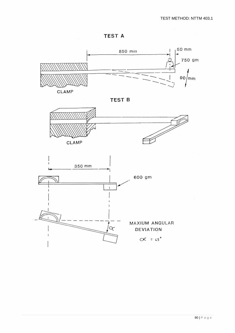
90 | P a g e
TEST METHOD: NTTM 403.1

91 | P a g e
TEST METHOD: NTTM 404.1
RETROREFLECTIVITY TESTING OF PAVEMENT MARKING
1. SCOPE
This procedure describes the method for determining the retroreflectivity (night visibility) of road
markings.
2. APPARATUS
(a) Mirolux Reflectometer and Associated Equipment;
(b) Global Positioning System (GPS);
(c) Suitable traffic control system.
3. STANDARD TEST SECTION LENGTH
FIGURE 1: STANDARD TEST SECTION LENGTH
Standard test site length is equivalent to 3 broken centre lines, as shown, approximately 27m.
4. SITE SELECTION
Selection of the test site shall be conducted as follows:
(a) randomly select the first test site;
(b) further test sites shall be selected at 10km intervals;
(c) test every 10km test site;
(d) test all lines over the length of the test site; and
(e) where no broken line exists conduct testing on unbroken lines over the equivalent distance for
the standard test site.

92 | P a g e
TEST METHOD: NTTM 404.1
5. PREPARATION
(a) Turn the instrument on and turn the lamp on. Warm up the instrument for 5 minutes;
(b) Ensure that the battery reading is greater than 115. A reading less than this will indicate the
battery is low and testing should be abandoned;
(c) Turn the lamp off and adjust the left-hand potentiometer to zero. Ensure the black knob on the
rear of the compartment is fully pushed in;
(d) Turn the lamp on and adjust the right hand potentiometer to the calibration figure for the
instrument;
(e) Recheck the zero as described above in step (c), and then recheck the calibration figure as
described above in step (d). Continue to recheck these figures until both the calibration
constant and zero figures read correctly;
(f) Conduct a test on the calibration panel and ensure that the reading displayed is between the
limits specified on the calibration panel. If the reading is outside of the specified limits the test
should be abandoned;
(g) The calibration must be checked prior to measuring each test line. A variation of 5 units or
more from one line to the next will indicate a low battery level.
6. TESTING
(a) Conduct 6 tests on each broken line in one direction (total 18 tests). Record all these results
and determine the average reading for each broken line;
(b) Conduct 6 tests on each broken line in the opposite direction (total 18 tests). Record all these
results and determine the average reading for each broken line;
(c) LHS edge line: Conduct 10 tests over the equivalent distance of 3 broken lines (27m), in the
direction of traffic flow. Record all these results and determine the average reading for the
LHS edge line;
(d) RHS edge line: Conduct 10 tests over the equivalent distance of 3 broken lines (27m), in the
direction of traffic flow. Record all these results and determine the average reading for the
RHS edge line;
(e) Take a GPS reading at the site;
(f) Record the chainage (relative to the nearest DPI ‘Permanent Reference Point’), location and
line being tested, including the direction of test;
(g) Draw the locations of the testing on a sketch or plan of the site;
(h) Repeat test any obvious outliers.

93 | P a g e
TEST METHOD: NTTM 404.1
FIGURE 2: EXAMPLE OF TEST PROCEDURE
7. CALCULATIONS
Determine the average of the test results for each line in each direction.
8. REPORTING
Report the following information:
(a) All test results;
(b) The averages for each test line in each test direction;
(c) Test locations;
(d) GPS co-ordinate of each section, and chainage;
(e) Sketch of each test site;
(f) Reflectometer gauge number and calibration constant;
(g) Date of test;
(h) Time of test;
(i) Seal description;
(j) Paint type;
(k) Glass bead type/size;
(l) Date of paint application;
(m) Testing company;
(n) Contractor;
(o) Line marking company, and;
(p) Direction of test;
(q) Calibration plate retro-reflectivity range, and;
(r) Calibration check result.

94 | P a g e
TEST METHOD: NTTM 404.1
NOTES ON TEST:
1. Where the centre line consists of 2 lines, test the LHS line in the direction of traffic flow, and
test the RHS line in the direction of traffic flow, i.e. test one line in each direction;
2. Where turning lines or other lines are marked within the length of the test section conduct a
minimum of 10 tests on each of these additional lines over the distance of the standard test
section;
3. Where double lines are marked conduct a minimum of 10 tests on each line in the direction of
traffic;
4. Where chevrons or other markings appear within the test section, conduct sufficient testing on
the markings in the direction of traffic flow;
5. The amount of calibration carried out during the testing depends upon the ability of the
instrument to remain charged and retain its calibration, and the speed of the operation.

95 | P a g e
TEST METHOD: NTTM 404.1

96 | P a g e
TEST METHOD: NTTM 404.3
RETROREFLECTIVITY TESTING OF PAVEMENT MARKING WET CONDITION
1. SCOPE
This procedure describes the method for determining the retro-reflectivity (night visibility) of road
markings, in the wet condition.
The method is to be used in conjunction with NTTM 404.1.
2. APPARATUS
(a) 10 ltr. Bucket;
(b) 10 ltrs. of potable water;
(c) Watch.
3. SITE SELECTION
Site selection shall be as specified in NTTM 404.1.
4. PREPARATION
The test condition is created by pouring approximately 10ltrs of water from a bucket on to the test
site.
5. METHODOLOGY
Pour from a height of approximately 0.5m above the pavement surface, onto the test site.
After 1 minute conduct retro-reflectivity testing in accordance with NTTM 404.1.
6. REPORTING
Report retro-reflectivity test results from both the dry and wet condition.
Conform to the requirements of NTTM 404.1.
NOTES ON TEST:
1. The water is poured evenly along the test site, so that a crest of water momentarily floods the
test site and its’ surrounding area.
97 | P a g e
TEST METHOD: NTTM 405.1
CERTIFICATION OF PAVEMENT LINE MARKING APPARATUS
1. SCOPE
This method sets out the procedure for the certification of pavement line marking application
apparatus.
2. APPARATUS
(a) Line marking apparatus;
(b) Wet Film Thickness comb or WFT wheel;
(c) Metal plates for Wet Film Thickness;
(d) Plastic bag or tray of at least 3 litres capacity;
(e) Plastic measuring cylinder with 2-litre capacity graduated in millilitres;
(f) Watch.
3. PROCEDURE
(a) Set paint pump pressure;
(b) Set back pressure regulator (if recycle circuit);
(c) Note settings and stall pressure;
(d) Note spray tip nozzle sizes;
(e) Nominate pattern to be calibrated;
(f) Turn off glass bead supply;
(g) Check application for nozzle wear and replace if necessary. (e.g. uneven application or
feathered edges);
(h) Check pattern spray width against spec and adjust if necessary;
(i) Nominate application road-speed;
(j) Check Wet Film Thickness in accordance with NTTM 401.1, (a WFT ‘wheel’ may be found
more accurate than a ‘comb’);
(k) Adjust application speed to meet target wft;
(l) Repeat steps (i) to (k) until target is achieved;
(m) Spray at identified speed and check length and gaps of pattern. Adjust if necessary;
(n) Turns glass bead supply on;
(o) Set bead – tank pressure;
(p) Using NTTM 402.1, calibrate to suit pattern and proposed application road speed;
(q) Apply full application to test deck and visually check for alignment and uniform application of
paint and glass beads;
(r) Repeat above steps (a) to (q) for various patterns and dimensions.

98 | P a g e
TEST METHOD: NTTM 405.1
Table 1 shows the correct volumes of glass beads required to give an application rate on the marked
line of approximately 0.30 kg/m2 for different line widths and road speeds. The glass bead volume
figures given in the table are calculated for an actual application rate of 0.34kg/m2. These figures are
used for calibrating the machine because there is a loss of beads between the bead dispenser and
the marked line and the volume is measured with beads not compacted.
TABLE 1 - VOLUME IN GLASS BEADS (mL) REQUIRED IN 10 SECONDS OF OPERATION
ROAD
SPEED
LINE
WIDTHS
km/h m.p.h. 75mm
(3")
100mm
(4")
125mm
(5")
150mm (6")
8 5 371 495 619 1207
13 8 603 804 1006 1207
16 10 742 990 1238 1484
Table 2 shows the volumes of Type 3 large glass beads required to provide a retained application
rate on the lane of approximately 0.400 kilograms / square metre for a variety of line pattern widths
and application road speeds.
The following table is to be used for a bead application rate at 0.4 kg/m2.
TABLE 2 - VOLUME OF TYPE 3 LARGE GLASS BEADS (mL) REQUIRED IN 10 SECS OF OPERATION
Millilitres Of Large Glass Beads / 10 Seconds
Line Width 100mm 150mm 200mm
Road Speed
5 km/hr
6 km/hr
7 km/hr
8 km/hr
9 km/hr
10 km/hr
11 km/hr
12 km/hr
13 km/hr
14 km/hr
15 km/hr
16 km/hr
370
450
520
590
660
740
820
890
960
1040
1110
1180
550
660
780
890
1000
1110
1220
1340
1440
1550
1660
1780
740
890
1040
1180
1340
1480
1630
1780
1930
2070
2220
2370
TEST METHOD: NTTM 405.1

99 | P a g e
4. REPORTING
(a) Report the following:
(b) Produce an application chart with pressure settings, nozzle sizes and application road speeds
for a variety of patterns as a guide for future operational setups;
(c) Date of test;
(d) Location of test;
(e) Testing officer.
NOTES ON TEST:
1. The maximum application speed is 12km/hr;
2. Each calibration should establish the % of beads lost during application in order to achieve the
retained target, and then calibrate the dispensing quantity to suit;
3. Low pressure or gravity delivery to a gravity dispenser will produce the best application results;
4. The figures above are for the specified RETAINED bead application rate of 0.4 kg/m2;
5. There is no allowance for loss of glass beads during the application process Roadmarking
Operators should establish the % of beads lost during application and calibrate to suit the
application retained rate.

100 | P a g e
INDEX OF TEST METHODS
TEST METHOD SECTION 5 - SAMPLING & TESTING
BITUMEN AND RELATED PRODUCTS
PAGE NUMBER
NTTM 500.1 Certification of Bitumen Sprayers 2

101 | P a g e
TEST METHOD: NTTM 500.1
CERTIFICATION OF BITUMEN SPRAYERS FOR USE ON NORTHERN TERRITORY ROAD PROJECTS DIVISION PROJECTS
1. SCOPE OF CALIBRATION
This test method sets out the tests and procedures for the calibration of bitumen sprayers.
This calibration method does not apply to the initial calibration of a bitumen sprayer. The calibration
of an extensively modified bitumen sprayer is beyond the scope of this test method.
This test method must be carried out under the supervision of an authorised Departmental
representative.
This test method uses selected tests from "Bitumen Sprayers", NAASRA 1989 (NOTE: 1). this
method is an interim calibration method to be used until the Department adopts the Austroads SDT
series test methods.
2. APPARATUS
i. Distribution Trough
The minimum requirements for the trough are:
(a) The total volume of calibration fluid sprayed must be collected in the trough.
(b) This trough must permit the sprayed calibration fluid to be separated transversely into
50mm sections, over the full width of spray.
(c) The trough design must permit the measurement of the quantity of calibration fluid in
each 50mm section by an approved means, e.g. Northern Territory Weights and
Measures approved dipsticks and conversion tables, depth to volume.
ii. Stopwatch
A stopwatch with an accuracy of + 1 sec.
iii. Torch
iv. Calibration Fluid
Fluid with:
(a) a Kinematic viscosity of 80 x 10m-6
m2/s to 110 x 10
-6 m
2/s;
(b) a density of 0.85 - 0.94 g/mL, and;
(c) a Dynamic Viscosity of 0.07 Pa.s to 0.1 Pa.s.

102 | P a g e
TEST METHOD: NTTM 500.1
3. PREPARATION
(a) Calibration Fluid
Viscosity and density testing are to be carried out in accordance with AS 2341, by an
organisation with a Quality Assurance Procedure (Q.A.P.) and/or NATA registration for these
tests acceptable to the Department.
The calibration certificate for the calibration fluid is valid for one month from the date of
calibration. Spray wagon calibration shall not proceed until the calibration fluid is within
acceptable limits.
(b) Motor Vehicle Act 1985;
i. The Spray Wagon Owner shall supply a copy of the current Motor Vehicle Registration
Certificate for inclusion in the calibration report.
ii. Record the bitumen sprayer owner's plant identity number for inclusion in the calibration
report.
(c) Temperature Gauges
i. The Spray Wagon Owner shall supply a thermometer with a range 0 – 250 o
C and
readable to 5oC with a current calibration acceptable to the Department. The calibration
should not be older than 2 years.
(d) Bitumen Sprayer Dipstick
i. Inspect the dipstick for any damage which would affect its calibration. Ensure that the
owner’s plant identity number is engraved on the dipstick.
(e) Bitumen Sprayer Tank
i. Inspect the interior of the empty tank for any obvious damage which would affect the
calibration of the dipstick (NOTE: 2).
ii. Record the safe filling level tank capacity for inclusion in the calibration report.
iii. Record the total tank capacity for inclusion in the calibration report.
(f) Spray Nozzles
i. All spray nozzles shall comply with the requirements of "Bitumen Sprayers", (NAASRA)
1989.
ii. Record the type of all spray nozzles for inclusion in the report.
iii. Inspect all nozzles to identify if previously used or unused. Record the date and any
other information stamped on nozzles.
iv. Unused Nozzles: will be deemed to comply for 24 months after successful completion of
all distribution tests. (NOTE: 3)
v. Used Nozzles: may be used if calibrated by an Authority acceptable to the Department
within the previous 6 months of the commencement of this calibration. These nozzles
will be deemed to comply for 24 months after successful completion of all distribution
tests. (NOTE: 3). A copy of the calibration certificate for the nozzles shall be supplied
prior to the calibration of the spray wagon.

103 | P a g e
TEST METHOD: NTTM 500.1
(g) Spray bar
i. Ensure the spray bar is located over the centre line of the distribution trough.
ii. Ensure the spray bar is level.
iii. Ensure the front face of the spray nozzles is parallel to the centre line of the spray bar.
iv. Record the spray bar type for inclusion in the calibration report.
4. PROCEDURE
(a) Ensure the trough is empty.
(b) Ensure all trough stopcocks are closed.
(c) Ensure the spray bar is full.
(d) Record the difference in height of the lowest point of the spray nozzles and the top of the
trough.
(e) Record the volume of calibration fluid within the bitumen sprayer tank prior to testing, with bar
circulating.
(f) Record over which 50mm sections the end spray nozzles are located.
(g) Record the pump speed during bar circulation of the calibration fluid.
(h) Record the manifold pressure during bar circulation of the calibration fluid.
(i) Instruct the spray wagon operator to commence spraying.
(j) Using the stopwatch, record the time of commencement of spraying.
(k) Do not permit the bitumen sprayer operator to adjust the pump speed.
(l) Record the pump speed during spraying.
(m) Record the manifold pressure during spraying.
(n) Record the time of cessation of spraying (approx. 50 seconds). (NOTE: 4)
(o) After the settling of the calibration fluid (NOTE: 5) in the bitumen sprayer tank, record the
volume of the remaining calibration fluid in the tank.
(p) After the settling of the calibration fluid in the trough, record the height of calibration fluid in
each 50mm section of the trough from the marked coloured plates located behind the viewing
tubes.

104 | P a g e
TEST METHOD: NTTM 500.1
5. REQUIREMENTS
(a) Transverse Distribution Test;
i. For a bitumen sprayer with an 8.0m spray bar.
Carry out transverse distribution testing for the following effective spray widths. (NOTE: 6).
Effective Spray Width Nozzles A4 EA4l Total Nozzles Total Trough
Sections
a) For 8m effective spray
width - 76 2 78 160
b) For 6.2m effective spray
width - 58 2 60 124
c) For 3.7m effective spray
width - 33 2 35 74
d) For 3.8m effective spray
width for twin tap - 34 2 36 75
Tank Levels:
1. 100 - 80% full;
2. 80 - 50% full;
3. < 50% full.
ii. For a bitumen sprayer with a 4.0m spray bar.
Carry out transverse distribution testing for the following effective spray width.
a) 4.0m – only
Effective spray width - Nozzles A4 EA4 Total Nozzles Total Trough
Sections
For 4.0m effective
spray width-
36 2 38 80
Tank Level:
1. 50-80% full.
iii. For all spray bar widths.
(b) The acceptable effective spray width shall be:
8.0m spray bar- 7.95 - 8.05m
6.2m spray bar- 6.15 - 6.25m
4.0m spray bar- 3.95 - 4.05m
3.7m spray bar- 3.65 - 3.75m
(c) No 50mm section is to differ from the mean by more than 20%, except sections outside
the end jets, which shall be averaged separately.
(d) Not more than two 50mm sections in any ten consecutive segments to differ from the
mean by more than 15%.
(e) Not more than four 50mm sections in any consecutive seven segments to differ from the
mean by more than 10%.

105 | P a g e
TEST METHOD: NTTM 500.1
iv. Testing Frequency
a) Calibration Fluid 3 months
b) T.D.T. 12 months
c) Spray Nozzles (used Without Calibration
Certificate)
12 months
d) Spray Nozzles (used With Calibration
Certificate)
24 months
e) Spray Nozzles (unused) 24 months
f) Thermometers 24 months
g) Pressure Gauge 24 months
b) Dipstick Calibration Check
The output calculated from the bitumen sprayer tank dipstick readings must be within + 50
litres of the total theoretical volume as calculated.
6. REPORTING
(a) Following successful completion of all tests, a report is to be presented to the Materials Testing
Manager for endorsement.
(b) Report Layout
i. Title Page;
ii. Bitumen Sprayer Calibration Certificate;
iii. Completed Quality Control Checklist;
iv. Calibration fluid test report;
v. Spray nozzle calibration certificate/s (used nozzles);
vi. Bitumen Sprayer Registration Certificate copy;
vii. Thermometer Calibration Certificate copies, if required;
viii. Worksheet 500(a), (Depth recording of every 50mm section of trough);
ix. Bitumen Sprayer Calibration Certificate.
(c)
i. All original recordings are to be compiled into a report and placed on file;
ii. A copy of the Bitumen Sprayer Calibration Certificate is to be supplied to the bitumen
sprayer owner. (Calibration Certificate to be endorsed by Materials Testing Manager).

106 | P a g e
TEST METHOD: NTTM 500.1
NOTES ON TEST:
1. NAASRA
National Association of Australian State Road Authorities, now known as AUSTROADS.
2. Bitumen Sprayer Tank
Obvious dents in the interior walls of the tank will affect the calibration of the dipstick. Where
obvious damage is found the dipstick must be recalibrated by an organisation with a Q.A.P.
for the recalibration of dipsticks, acceptable to the Department, prior to Transverse
Distribution Test commencement.
3. Spray Nozzles
If a Bitumen Sprayer is presented for calibration with any uncalibrated used spray nozzles,
replace these spray nozzles with new or calibrated spray nozzles.
Engrave the month and year of the commencement of the calibration period, on all spray
nozzles. Stamps all engraved spray nozzles once, with the logo stamp punch. Engrave and
stamp any new spare nozzles at the Bitumen Sprayer owner’s request. Do not re-engrave
the spray nozzle during the currency of the calibration period.
4. Duration of Spray
The duration of spray is approximately 50 seconds. This is only to ensure the trough is used
to near its maximum potential without risk of overflowing.
5. Settling of Calibration Fluid
The calibration fluid is deemed to be settled when air bubbles have departed from the
surface of the calibration fluid.
6. Effective Spray Width (E.S.W.)
The E.S.W. shall be the distance over which no individual (50mm section of trough) volume
varies from the mean volume by more than 20%.
7. Western Australian (W.A.) End Nozzles
Western Australian end spray nozzles may be used. The reduced maximum effective width
of spray (usually 0.3m less than the E.S.W. using "Copley" end spray nozzles) must be
recorded on the calibration certificate. The mean volume of calibration fluid per 50mm
section of trough will be determined by the total volume of fluid in the trough divided by the
‘Total Trough Sections” figure presented in the Table in 5 (a) minus six (0.3m/50mm).
Example 8.0m E.S.W. is reduced to 7.7m and the total volume of fluid is divided by (160-6)
154.
Or;
To maintain the effective spray width to 8.0m using WA end jets, increase the bar length by
adding 3 X A4 type jets.

107 | P a g e
TEST METHOD: NTTM 500.1
8. Currency of Calibration Certificate
Consecutive 12 month calibrations using the same spray nozzles shall be issued for a
maximum combined period of 2 years from the initial calibration of the nozzles.
Calibration certificates for spray wagons using previously used nozzles will be issued
for the remaining life of the nozzles, ie Nozzles that were calibrated and stamped 15
months previous will only be valid for 9 months from the consequent calibration, (total
nozzle life 24 months).
9. Calibration Trough
A suitable calibration trough is available at the CSR Depot at Tivendale Road, Berrimah.

108 | P a g e
TWML TEST METHOD: NTTM 500.1
CALIBRATION OF BITUMEN SPRAYERS
TEST RESULTS ON CALIBRATION FLUID
------------------------------------------------------------------------------------------------------------------------------------------------------------------------------
TO: REPORT NO:
ATTENTION:
------------------------------------------------------------------------------------------------------------------------------------------------------------------------------
Your request dated ........................ and signed by ........................................ has been received at the laboratory together with the
samples.
All the tests have been carried out as detailed in AS 2341, and the classification limits for cutback bitumen have been obtained from,
AS2158.
The following information was supplied relating to the samples:
FEATURES: CONTRACTOR:
SUPPLIERS IDENT.: PROJECT:
SAMPLED BY: LOCATION:
DATE SAMPLED: LAB. REF. NO.
Test results and classification limits are set out below:
--------------------------------------------------------------------------------------------------------------------------------------------------------------------------
PROPERTY TEST RESULTS CLASS. LIMITS
MIN. MAX.
-------------------------------------------------------------------------------------------------------------------------------------------------------------------------
Dynamic Viscosity of 25oC Pa.s.
Kinematic Viscosity mm2/s 80 110
Density at 25oC 0.85 0.94
------------------------------------------------------------------------------------------------------------------------------------------------------------------------
Prepared by: …………………………………………………………..

109 | P a g e
TEST METHOD: NTTM 500.1
NORTHERN TERRITORY
BITUMEN SPRAYER CALIBRATION CERTIFICATE
The sprayer described hereunder is hereby certified as complying with the Construction Division's requirements
for Bitumen Sprayers and subject to the conditions endorsed on this Certificate, is authorised to be used for
bituminous surfacing works undertaken by or for the Division.
The Division reserves the right to carry out any testing covered in NTTM 500.1 and or "Bitumen Sprayers"
NAASRA 1989, during the currency of this certificate.
Identification of Sprayer :
Registered Owner of Sprayer :
Vehicle Registration No. :
Make of Vehicle on which Sprayer is mounted :
Tank Capacity :
Tank Capacity Safe Filling Level :
Dipstick No :
Spray Bar Type :
Type and Size of Nozzles :
End Jet Type :
Spray Nozzle Stamp Date :
New Spray Nozzle’s will be required on :
Thermometer 1 Serial Number :
Thermometer 2 Serial Number :
Height of Nozzle above Ground :
Certificate No :
Maximum Effective Spray Width :
This Certificate Expires On :
......................................................................
for Manager Construction Division
This Certificate in no way removes the responsibility of the owner of the Sprayer to ensure compliance at all times with legal requirements,
covering the vehicle and its equipment, applicable to the Territory and State in which the vehicle is operated and is issued subject to the
Sprayer continuing to operate satisfactorily and may be cancelled at any time

110 | P a g e
TWML TEST METHOD: NTTM 500.1
CALIBRATION OF BITUMEN SPRAYERS
TRANSVERSE DISTRIBUTION TEST
COMPANY: DATE:
IDENFIFICATION OF SPRAYER: TIME:
REGISTRATION NO: DIPE. REP:
VEHICLE MAKE: COMPANY REP:
TANK CAPACITY: SPRAYER OPERATOR:
DIPSTICK NO: ON SITE:
BAR TYPE: LEFT SITE:
SPRAY NOZZLES: SPRAY WIDTH:
----------------------------------------------------------------------------------------------------------------------------------------------------------------------------
---
SEG. DEPTH SEG. DEPTH SEG. DEPTH SEG. DEPTH SEG. DEPTH SEG.DEPTH
1. _______ 31. ______ 61. ______ 91. ______ 121. ______ 151.______
2. _______ 32. ______ 62. ______ 92. ______ 122. ______ 152.______
3. _______ 33. ______ 63. ______ 93. ______ 123. ______ 153.______
4. _______ 34. ______ 64. ______ 94. ______ 124. ______ 154.______
5. _______ 35. ______ 65. ______ 95. ______ 125. ______ 155.______
6. _______ 36. ______ 66. ______ 96. ______ 126. ______ 156.______
7. _______ 37. ______ 67. ______ 97. ______ 127. ______ 157.______
8. _______ 38. ______ 68. ______ 98. ______ 128. ______ 158.______
9. _______ 39. ______ 69. ______ 99. ______ 129. ______ 159.______
10. _______ 40. ______ 70. ______ 100. ______ 130. ______ 160.______
11. _______ 41. ______ 71. ______ 101. ______ 131. ______ 161.______
12. _______ 42. ______ 72. ______ 102. ______ 132. ______ 162.______
13. _______ 43. ______ 73. ______ 103. ______ 133. ______ 163.______
14. _______ 44. ______ 74. ______ 104. ______ 134. ______ 164.______
15. _______ 45. ______ 75. ______ 105. ______ 135. ______ 165.______
16. _______ 46. ______ 76. ______ 106. ______ 136. ______ 166.______
17. _______ 47. ______ 77. ______ 107. ______ 137. ______ 167.______
18. _______ 48. ______ 78. ______ 108. ______ 138. ______ 168.______
19. _______ 49. ______ 79. ______ 109. ______ 139. ______ 169.______
20. _______ 50. ______ 80. ______ 110. ______ 140. ______ 170.______
21. _______ 51. ______ 81. ______ 111. ______ 141. ______ 171.______
22. _______ 52. ______ 82. ______ 112. ______ 142. ______ 172.______
23. _______ 53. ______ 83. ______ 113. ______ 143. ______ 173.______
24. _______ 54. ______ 84. ______ 114. ______ 144. ______ 174.______
25. _______ 55. ______ 85. ______ 115. ______ 145. ______ 175.______
26. _______ 56. ______ 86. ______ 116. ______ 146. ______ 176.______
27. _______ 57. ______ 87. ______ 117. ______ 147. ______ 177.______
28. _______ 58. ______ 88. ______ 118. ______ 148. ______ 178.______
29. _______ 59. ______ 89. ______ 119. ______ 149. ______ 179.______
30. _______ 60. ______ 90. ______ 120. ______ 150. ______ 180.______
----------------------------------------------------------------------------------------------------------------------------------------------------------------
--------------
MANIFOLD PRESSURE (BC): SPRAY TIME (SECS):
MANIFOLD PRESSURE (SP): DIPSTICK BEFORE:
PUMP SPEED (BC): DIPSTICK AFTER:
PUMP SPEED (SP): OUTPUT (LTRS):
% ERROR: THEORETICAL:

111 | P a g e
TEST METHOD: NTTM 500.1
CALIBRATION OF BITUMEN SPRAYERS
QUALITY CONTROL CHECKLIST
PLACE INITIAL BESIDE ITEM NUMBER
1. Calibration fluid viscosity is acceptable & certificate supplied);
2. Sprayer is registered. (Copy of certificate has been supplied);
3. Sprayer tank has been inspected and is free of debris and dents;
4. Instrument calibration certificates supplied;
5. Trough free of debris and damage;
6. Nozzles unused and/or calibration certificate checked;
7. Spray bar set up correctly;
8. End jets checked. (Extra bar length added if W.A. end jets used);
9. Dipstick Serial Number matches plant identity number an has been recorded for inclusion on
the certificate (Engrave number if none exists);
10. Trough depth - volume conversion cross-checked with contractor's representative (manual
conversion only);
11. Tank output (dips) - trough quantities, compare within 50 L;
12. All transverse distribution tests completed;
13. All 50 mm section outputs meet requirements;
Unused or calibrated nozzles stamped and dated.

112 | P a g e
INDEX OF TEST METHODS
TEST METHOD SECTION 6 - SAMPLING & TESTING CEMENT AND
CONCRETE
PAGE NUMBER
NTTM 601.1 Quality Control of Concrete - Wet Analysis 2

113 | P a g e
TEST METHOD: NTTM 601.1
QUALITY CONTROL OF CONCRETE - WET ANALYSIS
1. SCOPE
This test method is for determining the moisture content and sieve analysis of freshly mixed concrete.
It may be used to give an indication of the cement content of freshly mixed concrete provided the
sieve analyses of all the concrete components and that of the cement used are known.
Normally the test will be carried out in two stages, the first being at the point of discharge of the
concrete and the second in the laboratory.
2. APPARATUS AND PROCEDURE
STAGE 1 (POINT OF DISCHARGE)
A sample of concrete of about 25 kg shall be obtained from the freshly mixed concrete in accordance
with the procedures outlined in AS 1012.1. The sample shall be thoroughly mixed and a 10kg portion
(approx.) shall be placed in a previously weighed tray and weighed immediately. The mass of tray
and wet sample shall be recorded. The sample should then be protected as necessary for
transporting to the laboratory for the determination of moisture content.
A second portion of approximately 10kg mass shall be placed in a weighed dish and the mass
recorded. Water shall then be added to the dish and the concrete thoroughly mixed, allowed to stand
for 15-20 seconds and the water and cement poured off through a 75 /um AS Sieve. This process of
elutriation shall be repeated at least twice. The portion retained on 75/um sieve should be added to
the sample. The sample should then be protected as necessary for transporting back to the
laboratory.
STAGE 2 (IN LABORATORY)
The moisture content sample shall be dried out as quickly as possible over a gas ring or similar heat
source. The sample shall be considered to be fully dried out when two successive weighings, at least
30 minutes apart, are the same. Record the dry mass of the sample, plus tray.
The second portion shall be further elutriated until the wash is clear. The 75 um Sieve residue shall
be washed back into the dish and the dish and its contents dried out in an oven at 105°C - 110°C until
drying is complete.
When the sample is dry, a mechanical analysis shall be carried out in accordance with AS1141.11.
Also the ratio of the moisture content to the material passing the 75 um Sieve shall be reported, as
shall be the slump of the concrete sample.
3. COMMENTS ON APPLICATION OF TEST
1. Good reproducibility in the grading of freshly mixed concrete can be obtained by this procedure
for the analysis of wet concrete. For correct interpretation of the results however, especially
percentage passing the 75 um Sieve, the grading of the aggregates and cement used must be
known.
2. Experience has indicated that four hours directly over a gas burner is required to determine the
moisture content accurately, and also that the correct moisture content can only be determined
if the interval between initial mixing and commencement of drying does not exceed one hour.

114 | P a g e
TEST METHOD: NTTM 601.1
3. The benefits of using Wet analysis as an auxiliary to the usual quality control in the field are as
follows:-
The analysis will indicate serious departures from the specified grading, particularly
when dealing with concrete batch plants that have small stockpile reserves which
prevent pre-testing.
The analysis will indicate immediately any appreciable weighing fault in the batching
system.
Perhaps the most important aspect is the constant check on the water content, which
will indicate if the assessment of the aggregate moisture contents is correct and also
provides a check on the water gauge.

115 | P a g e
INDEX OF TEST METHODS
TEST METHOD SECTION 7 – PAVEMENT TESTING PAGE NUMBER
NTTM 701.1
NTTM 702.1
Benkleman Beam Testing Methodology
Field Permeameter testing of Bituminous Seals
2
7

116 | P a g e
TEST METHOD: NTTM 701.1
BENKELMAN BEAM DEFLECTION TEST
1. SCOPE
This test method sets out the procedure for measuring the deflection of a flexible pavement using the
Benkelman Beam.
2. APPARATUS
(a) Benkelman beam apparatus fitted with a suitable vibrator.
(b) Truck:
i. Load: The vehicle must have an 8.2 ± 0.2 tonne load over the rear axle
equally distributed by each set of dual wheels. The rear axle mass of
the test vehicle shall be determined with full tanks of fuel and chains
on board;
ii. Tyres: The following guidelines should be followed in respect to tyres for
Benkelman Beam vehicles. These requirements apply to the tyres on
the dual wheels of the ballasted axle;
Size: 10 x 20, preferably 12 ply but higher ply ratings are acceptable, i.e. 14
ply;
Construction: Diagonal ply (i.e. cross ply or bias ply);
Tread Pattern: “Highway” type. Lug type not acceptable;
Pressure: 550 kPa ± 10 kPa;
Spacing: Tyres should be 300 mm apart, measured centre to centre of the dual
wheels;
Wear: It is essential that all four tyres on the rear axle show the same degree
of wear.
iii. Tyre pressure gauge
(a) Thermometer (0-100OC) with 1
0 divisions;
(b) Asphalt hole punch and light oil;
(c) 10m tape;
(d) Notebook, worksheets;
(e) Camera.
3. DEFINITION
The rebound deflection bowl is the shape of the deflection profile as the truck moves off the test
point. It is determined from measurements of deflection using the Benkelman Beam, at 0mm,
300mm, 600mm, 900mm and 2700mm and 6000mm spacings.
4. PREPARATION
i. - Obtain truck capable of carrying 8.2t over the back axle, with correct axle tyre configuration;
- Ensure truck has chains and blocks for securing load;
- Check tyre pressure;
ii Arrange for a forklift or crane to load the ballast to equal 8.2t;

117 | P a g e
TEST METHOD: NTTM 701.1
ii. Ensure the distribution of 4.1t load over near wheel by measuring with mobile scales or
otherwise.
iii. Benkelman Beams
- Ensure beams are calibrated;
- Ensure both beams are functioning satisfactory;
- Ensure dial gauges are working;
- Ensure that the dial gauge vibrators are functioning.
iv. Traffic Control
- Arrange suitable traffic control measures, including staff, signs, flashing lights and
radios where required.
v. Staff
- 1 x distance measure and caller;
- 1 x Truck Driver;
- 2 x Beam Operators.
vi. Conduct test run to ensure all equipment is functioning correctly.
5. SETTING OUT
Include the following information in the report: -
i. Pavement Temperature;
ii. Air Temperature;
iii. Thickness of asphaltic concrete layer, if appropriate.
iv. Road name;
v. Road number from PRP Register;
vi. Lane No. Inbound or Outbound;
vii. Date and Time;
viii. Test location, chainage, wheel path, distance and pavement width.
Lanes are numbered from left to right, looking in the direction of traffic flow with lane 1 being the
outer or slow lane. Where there is a change in the number of lanes over the length under test, care
must be taken to indicate the direction and lane number. A sketch plan is to accompany the test
results.
Spacing of the test sites should be such that at least 10 measurements are taken in each length over
which the pavement and surrounding conditions appear uniform. The spacing of the test sites is
dependent on the length and uniformity of the section and the following table below may be used as
guide:
- 10m for all construction control testing, otherwise;
- 25m for section length less than 1 km;
- 50m for section length between 1 to 2km;
- 100m for section length between 2-5km;
- 200m for section length more than 5km.
iv. Deflections shall be measured in the wheel paths.

118 | P a g e
TEST METHOD: NTTM 701.1
6. PROCEDURE
(a) Select and mark the point on the pavement, which is to be tested. See Note 1;
(b) Centre the dual wheels of the truck approximately 1.5m behind the selected test site;
(c) Insert the probe of the Benkelman beam between the dual wheels and place it on the selected
test site (1.5m from the tip of the beam to the axle), ensuring that the tyres of the truck will not
touch the beams;
(d) Remove the locking pin from the beam and adjust the rear leg until the dial gauge is in the
midrange of its travel;
(e) Turn on the vibrator;
(f) Set the dial gauge at zero;
(g) Creep the truck slowly forward and take readings of the Benkelman beam gauge as the truck
moves past the zero point, 200mm, 400mm, 600mm, 900mm, 1,200mm and 1,500mm
spacings. Stop the truck 2.7m from the zero point and record the gauge reading when the rate
of recovery is equal or less than 25µm per minute;
(h) Drive the truck forward to 6m and record the gauge reading when the rate of recovery is equal
or less than 25µm per minute;
(i) Turn off the vibrator;
(j) For asphaltic concrete pavement, record the pavement temperature and air temperature at
least once every hour;
(k) Record the air and road temperature approximately every 1-2 hours;
(l) At each test site record and rate the pavement shape and condition including the surface type
and any cracking etc.
NOTES:
1. The truck should be parked for a minimum period of 3 minutes and the entire test shall
be completed within approximately 4 minutes;
2. Check the truck tyres every 2-3 hrs and if necessary adjust to specified pressure;
3. For chip seal surfaces pavement temperature is not required.
7. DATA COLLECTION
(a) Obtain traffic data records (if required) such as:
- traffic counts;
- percent commercial vehicles;
- traffic distribution;
- past traffic;
- future traffic predictions.
(b) Obtain information on the pavement configuration from previous records or conduct pavement
dippings.
TEST METHOD: NTTM 701.1

119 | P a g e
8. DATA ANALYSIS
8.1 Analysis of Field Data
Analyse the data to break the subject section of road into areas with similar values.
8.2 Required Deflection Data
Determine the maximum
deflection: (2 x dial gauge reading at 0mm distance)
Determine the Datum: (6000mm reading)
Determine the residual rebound: (maximum deflection – datum reading x 2) Note: can
be + or -
Determine the rebound
deflection: (maximum deflection - residual deflection)
Determine the D300: (300mm reading - datum) x 2
Determine the D600: (600mm reading - datum) x 2
Determine the D900: (900mm reading - datum) x 2
Determine the CBR: (D900 read off from Chart 5)
Determine the tolerable
deflection: (CBR Vs ESA’s from Chart 6)
Determine the D 200: (((300mm reading - 0mm reading)/300) *200) + 0mm
reading
Determine the D 250: (((300mm reading - 0mm reading)/300) *250) + 0mm
reading
8.3 Outliers
(a) Using the following procedure determine if any of the results are outliers.
i. Check for very large values.
Arrange the data in decreasing order, and calculate a statistic,
= (max value) - (next max value)
(max value) - (min value)
= (max) - (max - 1)
max - min
If exceeds the critical value given below, then discard max. (i.e. is an outlier)
n 3 4 5 6 7 8 9 > 10
(n.05) .941 .765 .642 .560 .507 .468 .437 .412
ii. In a similar way, we can test for very small values.
= min + 1 - min
max x - min
again, if exceeds the value in the table, then we discard it.

120 | P a g e
TEST METHOD: NTTM 701.1
(b) Remove any outliers from any further calculation and recalculate all valves, (with the
outliers removed).
8.4 Calculation
Determine if over the full length tested, there are distinct changes in the level of deflection
over significant lengths, to warrant splitting up these lengths for separate analysis.
NOTE: These variations may be due to changes in surfacing type, pavement thickness,
drainage conditions or topography.
After splitting the tested section into significant lengths, calculate the average (u), standard
deviation (s), characteristic deflection (u+fs) and coefficient of variation (CV) values for each
wheelpath and length. Abnormally high or low readings should be omitted form the statistical
analysis.
9. REPORTING
The following test results and general information shall be included in the report:
All beam testing field data recordings;
All deflection data test results;
Pavement surface and shape recordings;
Pavement temperature;
Pavement air temperature;
Checks for outliers;
Location plans;
Photographs;
Road name;
Road number from PRP Register;
Lane no’s;
Inbound / Outbound;
Test direction;
Date and time of investigation;
Test location, chainage and offset;
Length of project and spacing of test sites;
Pavement width.

121 | P a g e
TEST METHOD: NTTM 702.1
FIELD PERMEAMETER TESTING OF BITUMINOUS SEALS
1. SCOPE
This test method describes the procedure for determining the infiltration rate of pavement surfaces
using the Field Permeameter Ring. The test is applicable for thin asphalt and sprayed seal surfaces.
2. APPARATUS
Equipment required for the test includes:
(a) permeameter ring (bronze mould);
(b) slotted masses for securing the mould (approximately 20kg);
(c) suitable pavement sealing agents such as road marking paint, bitumen emulsion or potters
clay;
(d) 113mm diameter template for marking the test site;
(e) potters clay for sealing the gap between the mould and the road surface;
(f) stop watch for timing the drop in head height;
(g) squeegee bottle and water, food colouring and detergent for the test;
(h) worksheets.
3. PROCEDURE
The procedure consists of the following steps:
(a) Select the number and location of test sites to represent the characteristics of the seal being
evaluated.
(b) Remove any dirt or loose material from the area to be tested by brooming and washing down
with water, and then mop up any excess water on the surface.
(c) Place the permeameter on the pavement to ensure that the test surface is relatively flat.
(d) Mark the outline of the permeameter on the pavement surface with spray paint.
(e) Using the template, an annulus is marked on the nominated test site leaving an unmarked
inner diameter of 113mm for the test (10,000 mm2 surface area). The annulus of suitable
sealant may be made by paint, emulsion or potters clay, depending on which material is best
suited to the surface type under the prevailing weather conditions. To assist with drying times,
several light applications of a spray paint sealant may be required instead of one heavy
application. Other tests areas can also be prepared whilst the sealant dries or sets.
(f) A thick ring of potters clay is applied to the prepared annulus on the road pavement, ensuring
that all surface voids are filled, and a water uniform surface is achieved.
(g) Place the permeameter centrally onto the prepared ring of potter’s clay with the air bleed valve
on the highest side of the test site. Ensure that the permeameter is securely seated into the
potter’s clay and a watertight bond is achieved.
(h) Place approximately 20 kg of slotted masses onto the permeameter with the slots aligned to
allow access to the bleed valve.

122 | P a g e
TEST METHOD: NTTM 702.1
(i) Insert the plastic viewing tube into the permeameter. Ensure the viewing tube is inserted far
enough to come in contact with the stop lip of the permeameter.
(j) The air bleed valve is opened and the prepared water is poured in through the viewing tube to
fill the permeameter. When water commences to flow out of the air bleed valve, close the air
bleed valve whilst ensuring that all air has been expelled from the permeameter. The water
level is then filled up to the desired head height (h1), and the test commences.
(k) The time interval (T) for the water head in the viewing tube to fall from h1 to h2 is timed using a
stopwatch.
(l) Using the data obtained, the permeability of the sealed surface can be determined
approximately in accordance with Hvorslev falling head formulae given below:
k = D ln h1
11 (T) h2
(m) Describe the pavement seal type and condition.
4. REPORTING
Report the initial and final head height, the time taken for the water to drop from the initial to final
head height, pavement seal type and condition, the pavement temperature, the infiltration rate, and
the permeability as calculated using Hrorlev’s and the falling head equations.
NOTES ON TEST:
1. Use a fine grained potters clay, stoneware grade, e.g. Walkers white. The consistency of the
clay may need to be adjusted to ensure adequate workability.
2. Potable water shall be used for the testing, and this shall contain food colouring and
approximately one drop of detergent/litre.
3. The level of h1 is usually 600, 500, 400, and 300mm, and thus the level of h2, which is 100mm
less than h1, would be 500, 400, 300, and 200mm respectively.
TEST METHOD: NTTM 702.1

123 | P a g e
FIELD PERMEAMETER WORK SHEET
PROJECT:
LOCATION:
WHEEL PATH:
DATE:
TEST No.:
CHAINAGE:
OFFSET:
SURFACE DESCRIPTION:
DGA Asphalt
OGA Asphalt
SMA Asphalt
Seal
Slurry
DGA Asphalt
OGA Asphalt
SMA Asphalt
Seal
Slurry
DGA Asphalt
OGA Asphalt
SMA Asphalt
Seal
Slurry
AGGREGATE SIZE mm:
THICKNESS mm:
SURFACE CONDITION :
Corrugations,
Depressions ,
Shoving,
Level,
Rutting,
Corrugations,
Depressions Shoving,
Level,
Rutting,
Corrugations,
Depressions Shoving,
Level,
Rutting,
BITUMEN CONDITION:
Very Lively/New,
Lively
Dull,
Hard & Brittle
Rubber,
Very Lively/New,
Lively
Dull,
Hard & Brittle
Rubber,
Very Lively/New,
Lively
Dull,
Hard & Brittle
Rubber,
SURFACE TEXTURE:
Bleeding,
Flushed,
Black,
Smooth,
Matt,
Hungry,
Very Hungry
Raveling,
Stripping,
Delaminating
Bleeding,
Flushed,
Black,
Smooth,
Matt,
Hungry,
Very Hungry
Raveling,
Stripping,
Delaminating
Bleeding,
Flushed,
Black,
Smooth,
Matt,
Hungry,
Very Hungry
Raveling,
Stripping,
Delaminating
CRACKING:
Block,
Crescent Shaped,
Crocodile,
Diagonal,
Longitudinal,
Transverse,
Meandering,
Block,
Crescent Shaped,
Crocodile,
Diagonal,
Longitudinal,
Transverse,
Meandering,
Block,
Crescent Shaped,
Crocodile,
Diagonal,
Longitudinal,
Transverse,
Meandering,
CONTRACTOR:
MANUFACTURER:
SPEED ZONE:
TRAFFIC COMPOSITION:
PAVEMENT TEMPERATURE:
WEATHER CONDITIONS:
LOCAL SITE DRAINAGE:
COMMENTS ON SITE
CONDITIONS:
TEST No:
DROP IN
HEAD HEIGHT
CLOCK ELAPSED
TIME
CLOCK ELAPSED
TIME
CLOCK ELAPSED
TIME
h1 600 - h2 500 mm *
h1 500 - h2 400 mm
h1 400 - h2 300 mm
h1 300 - h2 200 mm
INFILTRATION RATE: *
COMMENTS ON TEST:

124 | P a g e
INDEX
SECTION 8 – AUSTRALIAN STANDARD TEST METHODS PAGE NUMBER
Australian Standard Test Methods 2

125 | P a g e
AUSTRALIAN STANDARD TEST METHODS
Method
No. Method
AS 1012 Methods of Testing Concrete
AS 1074 Steel Tubes and Tubulars for Ordinary Service
AS 1111 ISO Metric Hexagon Bolts and Screws
AS 1112-1 Style 1 Product Grades A & B
AS 1112-2 Style 2 Product Grades A & B
AS 1112-3 Product Grade C
AS 1112-4 Chamfered Thin Nuts Product Grades A & B
AS 1141 Methods for Sampling and Testing Aggregates
AS 1160 Bitumonious Emulsions for the Construction and Maintenance of Pavements
AS 1163 Structural Steel Hollow Sections
AS 1231 Aluminium and Aluminium Alloys – Anodic Oxidation Coatings
AS 1252 High Strength Steel Bolts with Association Nuts & Washers for Structural Engineering
AS 1273 Unplasticised PVC (UPVC) Downpipe and Fittings for Rainwater
AS 1289 Methods of Testing Soils for Engineering Purposes
AS 1302 Steel Reinforcing Bars for Concrete
AS 1304 Welded Wire Reinforcing Fabric for Concrete
AS 1345 Identification of the Contents of Pipes, Conduits and Ducts
AS 1379 Specification and Supply of Concrete
AS 1397 Steel Sheet and Strip-hot Dipped Zinc Coated or Aluminium / Zinc Coated
AS 1477 PVC Pipes and Fittings for Pressure Applications
AS 1478 Chemical Admixtures for Concrete, Mortar and Grout
AS 1554 Paints and Related Materials – Methods of Test
AS 1580 Structural Steel Welding
AS 1594 Hot Rolled Steel Flat Products
AS 1597 Precast Reinforced Concrete Box Culverts
AS 1672 Limes and Limestones – Limes for Building
AS 1722 Pipe Threads of Whitworth Form
AS 1725 Galvanised Rail-less Chain Wire Security Fences and Gates
AS 1734 Aluminium and Aluminium Alloys – Flat Sheet, Coiled Sheet and Plate
AS 1742 Manual of Uniform Traffic Control Devices: Part 3 – Traffic Control Devices for Works Roads
AS 1743 Road Signs – Specifications
AS 1744 Forms of Letters and Numerals for Road Signs

126 | P a g e
AUSTRALIAN STANDARD TEST METHODS
Method
No. Method
AS 1761 Helical Lock – Seam Corrugated Steel Pipes
AS 1762 Helical Lock – Seam Corrugated Steel Pipes – Design and Installation
AS 1906 Retroreflective Materials and Devices for Road Traffic Control Purposes
AS 2008 Residual Bitumen for Pavements
AS 2009 Glass Beads for Road Marking Materials
AS 2041 Buried Corrugated Metal Structures
AS 2053 Conduits and Fittings for Electrical Installations
AS 2144 Traffic Signal Lanterns
AS 2157 Cutback Bitumen
AS 2187 Explosives – Storage Transport and Use
AS 2276 Cables for Traffic Signal Installations
AS 2339 Traffic Signal Posts and Attachments
AS 2341 Methods of Testing Bitumen and Related Road Marking Products
AS 2349 Method of Sampling Portland and Blended Cements
AS 2350 Method of Testing Portland and Blended Cements
AS 2353 Pedestrian Push Button Assemblies
AS 2357 Mineral Fillers for Asphalt
AS 2423 Galvanised Wire Fencing Products
AS 2433 Plastics – Method for Exposure to Ultraviolet Lamps
AS 2439 Perforated Plastic Drainage and Effluent Pipe Fittings
AS 2700 Colour Standards for General Purposes
AS 2703 Vehicle Loop Detector Sensors
AS 2758 Aggregates and Rock for Engineering Purposes - Part 1 – Concrete Aggregates, Part 2 –
Aggregate for Sprayed Bitumonious Surfacing
AS 2809 Road Tank Vehicles for Dangerous Goods
AS 2876 Concrete Kerbs and Channels (Gutters) – Manually or Machine Placed
AS 2891 Methods of Sampling and Testing Asphalt
AS 2979 Traffic Signals Mast Arms
AS 3000 Electrical Installations (Known as the Australian/New Zealand Wiring Rules)
AS 3100 Approval and Test Specification – General Requirements for Electrical Equipment
AS 3108 Approval and Test Specification – Particular Requirements for Isolating Transformers and
Safety Isolating Transformers
AS 3155 Approval and Test Specification – Electrical Cables – Thermoplastic Insulated for Working
with High Voltages up to and including 0.6/kV
AS 3191 Approval and Test Specification – Electric Flexible Chords
AS 3568 Oils for Reducing the Viscosity of Residual Bitumen for Pavements
AS 3600 Concrete Structures
AS 3610 Formwork for Concrete
AS 3678 Structural Steel – Hot-Rolled Plates, Floor Plates and Slabs
AS 3679 Structural Steel – Part 1 – Hot-Rolled Bars and Sections

127 | P a g e
AUSTRALIAN STANDARD TEST METHODS
Method
No. Method
AS 3706 Geotextiles – Methods of Test
AS 3725 Loads on Buried Concrete Pipes
AS 3730.14 Guide to the Properties of Paints for Buildings – Part 14 – Undercoat-Solvent-Borne, Exterior
/ Interior
AS 3972 Portland and Blended Cements
AS 4025.1 Paints for Equipment including Ships – Solvent –Borne-Interior and Exterior-Full Gloss
Enamel
AS 4049.1 Paints and Related Materials – Road Marking Materials – Solvent-Borne Paint – For use with
Drop-On Beads
AS 4058 Precast Concrete Pipes (Pressure and Non-pressure)

128 | P a g e
SECTION 9 – NOT USED

129 | P a g e
SECTION 10 – NOT USED