Embed Size (px)
Citation preview

4
Mathematical Modelling of Air Drying by Adiabatic Adsorption
Carlos Eduardo L. Nóbrega1 and Nisio Carvalho L. Brum2 1Centro Federal de Educação Tecnológica, CEFET-Rio
2Universidade Federal do Rio de Janeiro, COPPE/UFRJ Brazil
1. Introduction
The careful control of ambient air moisture content is of concern in many industrial processes, with diverse applications such as in metallurgical processes or pharmaceutical production. In the air-conditioning field, the increasingly concern with sick building syndrome also brings humidity control into a new perspective. Underestimated ventilation rates might result in poor indoor air quality, with a high concentration of volatile organic compounds, smoke, bacteria and other contaminants. Epidemiological studies indicate a direct connection between inadequate levels of moisture and the incidence of allergies and infectious respiratory diseases. A popular method of lowering the concentration of contaminants is to increase the ventilation rates. In fact, the fresh air requirement per occupant/hour imposed by the current air-quality standard has doubled over the last three decades. Since the fresh air has to be brought to the thermal comfort condition, increased ventilation rates imply increased thermal loads, which in turn will demand chillers with increased cooling capacity. Accordingly, there is a trade-off between indoor air quality and energy consumption, which is also of main concern of private and public sectors. Figure (1.a) shows an evaporative cooling system. It essentially consists of a chamber through which air is forced through a water shower. It is a sound system from air-quality, energy consumption and ecological viewpoints. The air quality is provided by a continuous air room change, with no air recirculation. Since the cooling effect is provided by evaporation of water into air, the energy consumption is restricted to the pumping power, which is usually low when compared to the energy needs of a compressor. Unlike vapor-compression systems, which usually employ ozone-depleting refrigerants, evaporative cooling systems exclusively employ water as the refrigerant. Figure (1.b) shows that the evaporative cooling process is isenthalpic, which means that the air stream enthalpy remains unaltered as it flows through the evaporative cooler. Accordingly, the increase in the air stream humidity occurs at the expense of its own sensible energy, and the air stream is cooled and humidified as it crosses the evaporative cooler. Since the heat and mass transfer processes are mutually dependent, the air stream humidity at the inlet of the evaporative cooler has to be significantly low, if an appreciable cooling effect is to be achieved. Unfortunately this is not always the case, and this cooling technique is not as effective as traditional vapour-compression systems, being restricted to applications on low humidity areas (Khuen et al., 1998).
www.intechopen.com

Mass Transfer in Chemical Engineering Processes
70
Fig. 1. Evaporative cooling system
One possible way to overcome this restriction would be artificially dry the air stream before it is admitted to the evaporative cooler, which can be accomplished by using a solid sorbent air dryer. Adsorption is primarily used for component separation from a gaseous mixture, and is widely employed in the chemical industry. The main advantage is that the adsorptive material pore size can be designed for selective adsorption of a given component, allowing even trace amounts to be removed (Chung and Lee, 2009). However, the removal of moisture from air for comfort cooling has distinguished features from gas separation usually practiced in the chemical industry. Consider Figure (2.a), which shows an active desiccant rotor. It consists of a cylindrical drum, fitted with a micro-channel mesh, usually made of aluminum or plastic. The structure material is coated with silica-gel, which can be manufactured as a substrate. Silica-gel is a form of silicon dioxide derived from sodium silicate and sulfuric acid, which has good affinity to water vapor and an adsorbing capacity of as much as 40% of its own weight. Regular density silica gel typically offers an adsorptive area 400m2 per cm3, with an average porous radius corresponds to 11Å. The present model relies on the existence of an air layer in close contact with the solid, from which the adsorbed vapor molecules stem. The silica-gel affinity to water can be explained by considering that the state of any solid particle is considerably different, depending on its located on the core or on the solid surface. A particle located in the interior of the solid is neutral equilibrium, uniformly surrounded by other particles, and has minimum potential energy. Conversely, a particle on the surface is subjected to a greater potential energy, which is a representation of the required work to move the particle from the interior to the surface, agains the atractive molecules forces. The nearby vapor molecular are attracted form the air layer to the adsoprtive surface, in an effort to restore equilibrium (Masel, 1996). The desiccant wheel operates between two air streams, the process air stream, which is the stream to be dehumidified, and the regeneration stream, which is a high temperature air stream required to purge the humidity from the desiccant felt. At the process stream side, the humidity migrates from the air to the desiccant coated walls of the channel. Conversely, when the regeneration stream is forced through the micro-channels, the desiccant coat returns the humidity back to the air stream, which is dumped back to the atmosphere. Accordingly, the humidity at the outlet of the process stream can
www.intechopen.com

Mathematical Modelling of Air Drying by Adiabatic Adsorption
71
become extremely low, enabling a much more significant temperature drop through the evaporative cooler. Similarly to the evaporative cooling process, the heat and mass transfer in the desiccant cooling process are also intimately connected: Consider the adsorption process, in which the humidity is attracted to the desiccant felt from the air stream. As the air is dehumidified, two factors contribute to increase its temperature, namely the heat of adsorption, which is the heat released as the vapor molecules are adsorbed, and ordinary heat transfer from the micro-channel walls, which have been exposed to the high temperature regeneration stream during the previous period of time. Since each micro-channel can be taken as an adiabatic cell, it can be concluded that the decrease in air humidity must exactly match the increase in air sensible energy, with mutually dependent effects as earlier described. Accordingly, the air crosses the desiccant rotor isenthalpically as shown in Figure (2.b), in the opposite direction of the evaporative cooling, which has been supported by numerical and experimental evidence (Nobrega and Brum, 2009a, 2009b).
Fig. 2. Active desiccant rotor
The purpose of the modeling is to simulate what the process air outlet state would be, for given values of the inlet air state, length of the channel, period of revolution, desiccant material, regeneration temperature and other design parameters.
2. Mathematical model
The mathematical modelling of desiccant wheels is of key importance for equipment developers, so as to provide them with guidelines for improved design. It is also of importance to HVAC engineers, in order to access if the thermal comfort condition can be attained for a typical set of atmospheric conditions. The mathematical model relies on a number of simplifying assumptions, aiming at keeping the model (and its solution) as simple as possible, while retaining the physical meaning. An excellent review of the
www.intechopen.com

Mass Transfer in Chemical Engineering Processes
72
mathematical modelling of adsorptive dehumidification can be found in the literature (Ge et al., 2008). 1. The micro-channels are perfectly insulated. 2. Heat and humidity transients within the air are negligible. 3. All thermo-physical properties for the fluid and the solid are considered constant. 4. The flow is hydro-dynamically and thermally developed. 5. The heat and mass transfer coefficients are assumed to be uniform along the micro-
channel 6. Temperature and concentration distributions in the direction normal to the flow are
taken to be uniform (lumped) within the channel and the solid. 7. The adsorption heat is modeled as a heat source within the solid material
Fig. 3. Schematic of the flow channel with desiccant coating
Assumption (1) relies on symmetry between the cells, which can be represented by adiabatic surfaces. Assumption (6) is adopted in light of the small thickness of the desiccant layer (Shen & Worek, 1992), (Sphaier & Worek, 2006). Consider Figure (4.a), which represents a differential control volume which simultaneously encloses the desiccant layer and the flow channel. The mass conservation principle applied to the depicted control volume yields:
1
10wmY Y W
m fu T x L t
(1)
Consider Figure (4.b), which represents a differential control volume which solely encloses the desiccant layer. The mass conservation principle applied to the depicted control volume yields
2ww
h
m Wf h Y Y
d L t
(2)
Figure (5.a) represents a differential control volume which simultaneously encloses the desiccant layer and the air stream. The energy conservation principle applied to the depicted control volume yields
www.intechopen.com

Mathematical Modelling of Air Drying by Adiabatic Adsorption
73
Fig. 4. Differential control volumes for mass balances
1 1
1
10w wm HH H
mu T x L t
(3)
Consider Figure (5.b), which represents a differential control volume which solely encloses the airstream. The mass conservation principle applied to the depicted control volume yields:
1 1 11
1
12 2w h w
H H Hm h Y Y h T T
u T x Y
(4)
In which the first term on the right hand side stands for the heat transfer between the sorbent and the air, whereas the second term represents the heat released during the adsorption. Defining the following non-dimensional parameters,
*
1
1
2 h hh d xx
Hm
T
(5)
* 2 h h
w wr
h d xtt
m C (6)
After extensive algebra, Equations (1)-(4) can be rewritten as
* w
YY Y
x
(7)
www.intechopen.com

Mass Transfer in Chemical Engineering Processes
74
Fig. 5. Differential control volumes for energy balances
2* w
WY Y
t
(8)
1* w
TT T
x
(9)
1*w
w w
TT T Y Y
t
(10)
With
21
1
wrC
Hf
T
(11)
21
1
Q
H
T
(12)
Equation (12) represents the heat of adsoprtion, released as the vapor molecule is adsorbed within the silica-gel. The adsorption heat is comprised of the condensation heat plus the wettability heat, which accounts for reducing the degrees of movement freedom of a gas molecule from three to two, as it is captured by a surface. The current modeling allows different approaches to to the adsoprtion heat, as both analytical and experimentally obtained expressions for Q could be easily fitted to Eq. (12). For regular density siilica-gel, the following expression was experimentally obtained (Peasaran & Mills, 1987),
www.intechopen.com
Mathematical Modelling of Air Drying by Adiabatic Adsorption
75
12400 3500 , 0.051400 2950 , 0.05
Q W W
Q W W
kJ/kg (13)
It shows that the heat release is not constant during the adsorption process, exhibiting a small reduction as the adsorption develops. This could be explained by observing that the first adsorbed molecules are attracted to the most energetically unbalanced sites. As the moisture uptake continues, the remaining spots to be occupied require less bonding energies, approaching ordinary latent heat as the solid becomes saturated. From the mathematical point of view, the problem is still undetermined, since there are five unknowns (T1, Tw, Y, Yw and W) and only four equations, (7) to (10). The missing equation is the adsorption isotherm, which is characteristic of each adsorptive material. For regular density silica-gel, the following expression was experimentally obtained,
2
3 4
0.0078 0.0579 24.16554
124.78 204.2264w W W
W W
(14)
Equations (15) and (16) are auxiliary equations, which relates the partial pressure of the air layer with the absolute humidity,
3816.44exp 23.196
46.13wsw
PT
(15)
0.62188 0.62188w ww
atmatm ww
ws
pY
pp pp
(16)
The periodic nature of the problem implies an iterative procedure. Both initial distributions of temperature and humidity within the solid are guessed, and equations (7) to (10), assume the form of tridiagonal matrices, as a result of the discretization using the finite-volume technique, with a fully implicit scheme to represent the transient terms (Patankar, 1980).. By the end of the cycle, both calculated temperature and moisture fields are compared to the initially guessed. If there is a difference in any nodal point bigger than the convergence criteria established for temperature and moisture content,
( ,0) ( )( ,0). .
( ,0)w w
tempw
T x T guess xCrit Conv
T x
(17)
( ,0) ( )( ,0)
. .( ,0)mass
W x W guess xCrit Conv
W x
(18)
the procedure is repeated, using the calculated fields as new guesses for the initial distributions. Figure (6) shows a simplified fluxogram for the numerical solution. Figures (7) and (8) show mass and temperature distributions along the desiccant felt, at selected angular positions. The curves relative to 0 and 2π are indistinguishable, as the periodic behaviour was attained. The average “hot outlet” enthalpy during a cycle is defined as
*0
1 hp
ho hoh
H H dtP
(19)
www.intechopen.com

Mass Transfer in Chemical Engineering Processes
76
Since the wheel is to store neither energy nor mass after a complete cycle,
i i o om H m H (20)
* *0 0
1 1h cp p
h hi c ci h ho c coh c
m H m H m H dt m H dtp p
(21)
the normalized difference between the two sides of equation (21) is defined as the Heat Balance Error (HBE), which was found to be of the order of 0.1% for all simulations carried.
* *0 0
1 1( )h cp p
h hi c ci h ho c coh c
h hi c ci
m H m H m H dt m H dtp p
HBEm H m H
(22)
Fig. 6. Fluxogram of the numerical solution
www.intechopen.com

Mathematical Modelling of Air Drying by Adiabatic Adsorption
77
0 0.2 0.4 0.6 0.8 1
non-dimensional position, (x*)
0
0.1
0.2
0.3
0.4
So
lidH
umid
ityC
onte
nt,W
(x*)
0, 2
Fig. 7. Mass distributions at selected angular positions, P*40.0, NTU=16.0, Treg=100°C.
0 0.2 0.4 0.6 0.8 1
non-dimensional position, x*
20
40
60
80
100
TW
(x*)
, C
0, 2
3
Fig. 8. Temperature distributions at selected angular positions P*40.0, NTU=16.0, Treg=100°C.
www.intechopen.com

Mass Transfer in Chemical Engineering Processes
78
3. Results
Since the active desiccant dehumidification is an isenthalpic process, it is not possible to establish a definition for the efficiency based on enthalpy. Accordingly, it is usual do define a dehumidification effectiveness as
ci codw
ci
Y Y
Y
0 2 4 6 8 10
non-dimensional position, x*
0
0.2
0.4
0.6
dw
Treg = 60C
Treg = 80C
Treg = 100C
Treg = 120C
Fig. 9. Effectiveness-NTU chart, P*=10.0
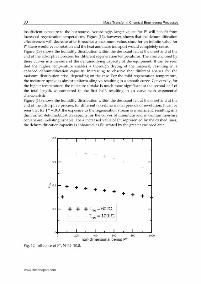
The non-dimensional position defined by Eq. (5) has a remarkable similarity to the NTU parameter, commonly found in heat exchanger analysis. Accordingly, Figure (9) shows the influence of the micro-channel lentgh over the dehumidification effectiveness. It can be seen that the regeneration temperature has a significant influence over the moisture removal. Figure (9) shows the existence of an optimum micro-channel length, which can be explained by observing that the regeneration stream is admitted at x* = 0. Accordingly, the closer the position is to the end of the channel (x* =10.0), the lower will be the temperature, allowing for some of the moisture to be re-sorbed by the desiccant felt (Zhang et al., 2003). Figure (10) shows that, for higher non-dimesional periods of revolution P*, the optimum length is higher, due to the longer exposure to to regeneration stream and consequential higher average temperatures along the desiccant felt. Figure (11) shows the influence of the non-dimensional period of revolution over the effectiveness as a function of the regeneration temperature. It can be seen that for a moderate value for the non-dimensional period (P* = 10.0), the effectiveness is oblivious to an increase in regeneration temperature, due to an
www.intechopen.com

Mathematical Modelling of Air Drying by Adiabatic Adsorption
79
0 2 4 6 8 10
Non-dimensional position, x*
0
0.2
0.4
0.6
0.8
dw
Treg = 60C
Treg = 80C
Treg = 100C
Treg = 120C
Fig. 10. Effectiveness-NTU chart, P*=80.0
40 60 80 100 120
Regeneration Temperature, Thi (C)
0.2
0.3
0.4
0.5
0.6
0.7
0.8
dw
P* = 10.0
P* = 40.0
P* = 80.0
Fig. 11. Influence of P*, NTU=10.0, Thi = 100°C
www.intechopen.com
Mass Transfer in Chemical Engineering Processes
80
insufficient exposure to the hot source. Accordingly, larger values for P* will benefit from increased regeneration temperatures. Figure (12), however, shows that the dehumidification effectiveness will decrease after it reaches a maximum value, since for an infinite value for P* there would be no rotation and the heat and mass transport would completely cease. Figure (13) shows the humidity distribution within the desiccant felt at the onset and at the end of the adsorptive process, for different regeneration temperatures. The area enclosed by these curves is a measure of the dehumidifying capacity of the equipment. It can be seen that the higher temperature enables a thorough drying of the material, resulting in a enhaced dehumidification capacity. Interesting to observe that different shapes for the moisture distribution arise, depending on the case. For the mild regeneration temperature, the moisture uptake is almost uniform aling x*, resulting in a smooth curve. Conversely, for the higher temperature, the moisture uptake is much more significant at the second half of the total length, as compared to the first half, resulting in an curve with exponential characteristic. Figure (14) shows the humidity distribution within the desiccant felt at the onset and at the end of the adsorptive process, for different non-dimensional periods of revolution. It can be seen that for P* =10.0, the exposure to the regeneration stream is insufficient, resulting in a diminished dehumidification capacity, as the curves of minimum and maximum moisture content are undistinguishable. For a increased value of P*, represented by the dashed lines, the dehumidification capacity is enhanced, as illustrated by the greater enclosed area.
0 200 400 600 800 1000
non-dimensional period P*
0
0.2
0.4
0.6
0.8
dw
Treg = 60CTreg = 100C
Fig. 12. Influence of P*, NTU=10.0.
www.intechopen.com

Mathematical Modelling of Air Drying by Adiabatic Adsorption
81
0 0.2 0.4 0.6 0.8 1
Non-Dimensional Position, X*
0
0.2
0.4
0.6
Sol
idH
umid
ityC
ont
ent,
W(x
*)
Thi = 50C
Thi = 90C
Fig. 13. Influence of Thi on the Humidity Distribution, NTU=16.0, P* = 40.0
0 0.2 0.4 0.6 0.8 1
Non-Dimensional Position, x*
0
0.1
0.2
0.3
0.4
So
lidH
umid
ityC
onte
nt,W
(x*)
P* = 10.0
P* = 40.0
Fig. 14. Influence of P* on the Humidity Distribution, NTU=10.0, Thi = 100°C
www.intechopen.com

Mass Transfer in Chemical Engineering Processes
82
Bearing in mind that the outside air atmospheric conditions can present a significant variation throughout the day, it is usefull to define a dynamic control for the desiccant rotor operation. For instance, supposing a steady increase of 30% in outside air relative humidity, how much would be the required increase in P*, so as to obtain a constant humidity at the process air stream outlet? Figure (15) shows the results for different increasing values for the regeneration temperature. It can be seen that for T = 60°C, an increase in 10% of the process air stream inlet will require the period of revolution to double, being unable to respond to a further increase of the relative humidity. Conversely, a higher regeneration temperature such as T = 100°C will only require a small increase in the period P*, being able to respond to a relative humidity of process air stream inlet as high as 90%.
60 70 80 90Process Air Stream Inlet Relative Hum. (%)
8
12
16
20
24
P*
Thi = 100CThi = 80C
Thi = 60C
Fig. 15. Required increase in P*=10.0
4. Conclusion
A mathematical model for the heat and mass transfer on a hygroscopic material was developed, and resulting set of partial differential equations was solved using the finite-volume technique. The results showed that the process air stream outlet condition is strongly influenced by the regeneration temperature, as well as of the non-dimensional period of revolution. It was also shown that an increase on the outside air humidity can be easily handled by increasing the non-dimensional period of revolution, as long as a temperature of regeneration of at least 100°C is provided. The results for the humidity distribution along the desiccant felt show that the moisture removal capacity of silica-gel is limited, which opens an opportunity for the application of more selective materials. However, it shouldn´t be disregarded that a greater affinity to water vapour also implies a
www.intechopen.com

Mathematical Modelling of Air Drying by Adiabatic Adsorption
83
greater amount of energy to remove the water vapour during the desorptive period. This could be of vital importance for the economic feasibility of this technology, unless an inexpensive thermal source is available.
5. Nomenclature
a constant c constant Cwr wall specific heat (kJ/Kg K) d constant dh hydraulic diameter (m) f desiccant mass fraction h heat transfer coefficient (KW/m2) hy convective mass transfer coefficient (kg/m2s) H enthalpy of air (kJ/kg) L length of the wheel (m)
1m air mass flow rate (kg/s) mw mass of the wall (kg) P period of revolution Patm atmospheric Pressure (Pa) Pws saturation pressure (Pa) Q heat of adsorption (kJ/kg) t time (s) T temperature (C) u air flow velocity (m/s) Y air absolute humidity (kg/kg air) YL adsorbed air layer absolute humidity (kg/kg air) W desiccant humidity content (kg of moisture/kg of desiccant) x coordinate (m)
Greek letters
1 auxiliary parameter 2 auxiliary parameter w relative humidity of air layer effectiveness
Subscripts
ci cold inlet co cold outlet hi hot inlet ho hot outlet sat saturation w desiccant channel wall 1 air
Superscript
* non-dimensional
www.intechopen.com
Mass Transfer in Chemical Engineering Processes
84
6. References
Chung, J.D.; Lee, D.Y., “Effect of Desiccant Isotherm on the Performance of Desiccant Wheel”, International Journal of Refrigeration, 2009; (32), pp. 720-726.
Close, D.J., 1983. Characteristic Potentials for Heat and Mass Transfer Processes. International Journal of Heat and Mass Transfer, 1983, 26(7), pp.1098-1102.
Ge, T.S.; Li, Y.; Wang, R.Z., Dai, Y.J.., A Review of the Mathematical Models for Predicting Rotary Desiccant Wheel, Renewable and Sustainable Energy Reviews, 2008, (12), pp. 1485-1528.
Kuehn, R.I., (1996) Principles of Adsorption and Reating Surfaces, New York NY: J. Wiley & Sons, Unites States
Masel, T.H., Ramsey, J.W., Threlkeld, J.L., (1998) Thermal Environmental Engineering, 3rd Upper Saddle River, NJ: Prentice-Hall, Unites States
Niu, J.L.; Zhang, L.Z., (2002)Effects of Wall Thickness on Heat and Moisture Transfer in Desiccant Wheels for Air Dehumidification and Enthalpy Recovery, International Communications in Heat and Mass Transfer, 2002, (29), pp. 255-268.
Nobrega, C.E.L.; Brum, N.C.L., Influence of Isotherm Shape over Desiccant Cooling Cycle Performance, Heat Transfer Engineering, 2009, 30 (4), pp.302-308.
Nobrega, C.E.L.; Brum, N.C.L., Modeling and Simulation of Heat and Enthalpy Recovery Wheels, Energy, 2009, (34): 2063-2068.
Patankar, S., Numerical Heat Transfer and Fluid Flow, (1980) Boston, Ma: Hemisphere Publishing Co, United States.
Pesaran, A.A., Mills, A.F., Moisture Transport in silica Gel Packed Beds-Part I , International Journal of Heat and Mass Transfer, 1987; (30): 1051-1060.
Shen, C.M..; Worek, W.M., 1992. The Effect of Wall Conduction on the Performance of Regenerative Heat Exchangers, Energy, 1992, (17),pp.1199-1213.
Sphaier, C.M.; Worek, W.M., (2006), The Effect of Axial Diffusion on Enthalpy Wheels, International Journal of Heat and Mass Transfer, 2006, (49), pp. 1412-1419.
Zhang, X.J., Dai, Y.J., Wang, R.Z.; “A Simulation Study of Heat and Mass Transfer in a Honeycomb Structure Rotary Desiccant Dehumidifier”, Applied Thermal Engineering, 2003, (23),pp. 989-1003.
www.intechopen.com

Mass Transfer in Chemical Engineering ProcessesEdited by Dr. Jozef Markoš
ISBN 978-953-307-619-5Hard cover, 306 pagesPublisher InTechPublished online 04, November, 2011Published in print edition November, 2011
InTech EuropeUniversity Campus STeP Ri Slavka Krautzeka 83/A 51000 Rijeka, Croatia Phone: +385 (51) 770 447 Fax: +385 (51) 686 166www.intechopen.com
InTech ChinaUnit 405, Office Block, Hotel Equatorial Shanghai No.65, Yan An Road (West), Shanghai, 200040, China Phone: +86-21-62489820 Fax: +86-21-62489821
This book offers several solutions or approaches in solving mass transfer problems for different practicalchemical engineering applications: measurements of the diffusion coefficients, estimation of the mass transfercoefficients, mass transfer limitation in separation processes like drying, extractions, absorption, membraneprocesses, mass transfer in the microbial fuel cell design, and problems of the mass transfer coupled with theheterogeneous combustion. I believe this book can provide its readers with interesting ideas and inspirationsor direct solutions of their particular problems.
How to referenceIn order to correctly reference this scholarly work, feel free to copy and paste the following:
Carlos Eduardo L. No ́brega and Nisio Carvalho L. Brum (2011). Mathematical Modelling of Air Drying byAdiabatic Adsorption, Mass Transfer in Chemical Engineering Processes, Dr. Jozef MarkoÅ¡ (Ed.), ISBN: 978-953-307-619-5, InTech, Available from: http://www.intechopen.com/books/mass-transfer-in-chemical-engineering-processes/mathematical-modelling-of-air-drying-by-adiabatic-adsorption

© 2011 The Author(s). Licensee IntechOpen. This is an open access articledistributed under the terms of the Creative Commons Attribution 3.0License, which permits unrestricted use, distribution, and reproduction inany medium, provided the original work is properly cited.