Embed Size (px)
Citation preview
MATHSM: medial axis transform toward
high speed machining of pockets
Gershon Elbera,*, Elaine Cohenb, Sam Drakeb
aFaculty of Computer Science, Department of Computer Science, Technion—Israel Institute of Technology, Haifa, IsraelbDepartment of Computer Science, University of Utah, SLC, Utah, USA
Received 31 December 2003; received in revised form 9 April 2004; accepted 2 May 2004
Abstract
The pocketing operation is a fundamental procedure in NC machining. Typical pocketing schemes compute uniform successive offsets or
parallel cuts of the outline of the pocket, resulting in a toolpath with C1 discontinuities. These discontinuities render the toolpath quite
impractical in the context of high speed machining (HSM).
This work addresses and fully resolves the need for a C1 continuous toolpath in HSM and offers MATHSM, a C1 continuous toolpath for
arbitrary C1 continuous pockets. MATHSM automatically generates a C1 continuous toolpath that consists of primarily circular arcs while
maximizing the radii of the generated arcs and, therefore, minimizing the exerted radial acceleration. MATHSM is especially suited for
machining of elongated narrow pockets.
q 2004 Elsevier Ltd. All rights reserved.
Keywords: Voronoi diagrams; Medial axis transform; High speed machining; Lines and arcs; Bi-arcs
1. Introduction and related work
Pocketing is one of the most common operations in NC
machining applications [2–4,6,10–13,16,19,20,22]. For
example, forming die-cavities [3] is one such application.
It requires machining at different levels of several parallel
cutting planes that define various pockets. A closed shape,
denoted the outline of the pocket, is prescribed in a
pocketing operation, possibly with islands, and a toolpath
is generated to machine the interior of the shape, cleaning it
to a prescribed depth. In many applications the bottom of the
pocket is planar, an assumption we make in this paper unless
otherwise stated. We consider possible extensions to non-
planar bottoms toward the end of this paper.
Two major approaches exist to generate toolpaths for
pocketing operations. The first is based on the intersection
of the outline of the pocket with parallel and equally spaced
0010-4485//$ - see front matter q 2004 Elsevier Ltd. All rights reserved.
doi:10.1016/j.cad.2004.05.008
* Corresponding author. Tel.: C972-4-829-4338; fax: C972-3-829-
1128.
E-mail addresses: [email protected] (G. Elber), cohen@cs.
utah.edu (E. Cohen), [email protected] (S. Drake).
planes. By connecting the parallel adjacent segments that
trim the pocket domain into a zig-zag motion, a complete
toolpath is constructed [2,11,19,20]. This approach is
similar to the scan conversion scheme used in computer
graphics to render polygonal domains and fill them with
pixels [9]. The different scanline segments are then
connected into a C0 continuous zig-zag toolpath.
The second approach offsets the outline(s) of the pocket
by equally spaced offset distances, and employs these
successive offsets to derive a toolpath [4,10,16]. Offsets of a
C1 continuous outline can yield C1 discontinuities in regions
where the radius of curvature of the curve is larger than the
offset distance. Hence, in general, this offset-based toolpath
is also C0 continuous.
Both schemes typically work with outlines formed from
lines and arcs. Use of lines alone to approximate the outline
risks the loss of C1 continuity in the outline’s approximation.
Hence, it is desirable to use arcs as well as lines, in the
approximating the outline. This makes it possible to achieve
C1 continuity where the radius is larger than the offset
distance and also, since many NC machines support an arc
instruction, it reduces the size of the generated G-codes.
Computer-Aided Design 37 (2004) 241–250
www.elsevier.com/locate/cad
G. Elber et al. / Computer-Aided Design 37 (2004) 241–250242
One approach to machining pockets with freeform curve
outlines is to approximate the freeform shape using arcs
[1,3,15]. Usually, the error between the freeform spline
curve and two successive arcs, or bi-arcs, is approximated
simultaneously, achieving the ability to approximate
inflection points in the curve. Errors are typically measured
in the LN sense, although the L2 norm has been employed as
well [15].
Offset computation directly from the freeform outline
curve is also quite common and robust (see Ref. [5] for a
recent survey), and is desirable for several reasons. The
parameterization of the original curve can be preserved, and
hence, the association between the original geometry and its
offset is maintained. In addition, the resulting offset
consisting of spline segments can be more efficiently
downloaded to an NC machine that supports spline motion
interpolation. Finally, the bi-arcs approximation introduces
another phase of approximation that also increases the data
sets. The problem, however, of clipping or trimming the
self-intersecting freeform curves in the resulting offsets is
considered a difficult one. In Ref. [6], analytic distance maps
are employed to robustly trim both local and global self-
intersections in offsets of freeform curves. The direction of
robust toolpath generation using direct spline offset
computations should, therefore, be further pursued.
Other related works on NC pocket operations have
attempted to look at optimization issues. Examples include
consideration of successive application of tools with
decreasing radii [22], so as to reduce the overall machining
time, or alternatively, minimizing the number of retractions
in zig-zag [2,19,20] and offset [4] type toolpaths. The latter
has an exponential-expected time complexity due to the
ability of reducing the toolpath traversal problem to the
traveling salesman problem (TSP).
High speed machining (HSM) is an NC machining pro-
cedure that is becoming more and more common [14,18,21].
Unfortunately, both the zig-zag toolpath and the offsetting
toolpath generation approaches introduce multiple C1
discontinuities into the toolpath, making it unsuitable for
HSM applications. Recently, several attempts have been
made to alleviate these difficulties. One approach employs a
spiral motion that starts at the center of the pocket and
spirals out until it reaches the outline [14,18]. The spiral
toolpath has an infinite curvature at the limit, if the spiral
starts at the center. Furthermore, it is unclear how to
initialize the spiraling process as well as bring the tool to its
proper cutting depth. While the spiraling scheme can work
reasonably well in almost circular pockets, it also becomes
arbitrarily inefficient when elongated pockets are con-
sidered. Similar difficulties might result when pockets with
complex shapes are considered. Other approaches include
trochoidal milling [21] where the toolpath is following a
trochoidal path. This scheme is used mainly to handle
locally C1 discontinuities in the pocket outline, converting
C1 discontinuities into small loops that connect the adjacent
pieces, thereby forming a C1 continuous toolpath.
In our work, we propose a different scheme to handle the
HSM of arbitrary C1 continuous pockets. The generated
toolpath consists of arcs of complete circles of as-large-as-
possible radii, or half that much, and segments that connect
consecutive arcs. This automatically generated tool path is
especially suited for narrow and elongated pocket regions
that are difficult to machine even using traditional toolpath
generation schemes. Further, the constructed toolpath is
guaranteed to be C1 continuous, maximizing the benefits
that can be drawn from the HSM schemes.
In Section 2, the basic algorithm is considered. In
Section 3, several examples are presented, including NC
machining tests we have conducted. In Section 4, several
possible extensions are discussed and finally, we conclude
in Section 5.
2. The basic MATHSM toolpath algorithm
Given a freeform closed curve, C(t), possibly with
islands, Ii(ti), we seek the medial axis transform (MAT) of
the geometry for reasons to be explained shortly. Robust
algorithms to approximate the MAT of freeform curves in
the plane have begun to appear [7,8,17]. Alternatively, one
can employ one of the existing piecewise bi-arc and/or
piecewise line-arc approximation methods for freeform
curves and use MAT computation for lines and arcs—an
approach that nowadays is considered robust. For example,
the VRONI [13] package derives the MAT of outlines
formed of lines and arcs. In this work, and in all presented
examples, the VRONI package was used to derive the MAT
by first converting the freeform spline into a bi-arc
approximation with prescribed tolerance.
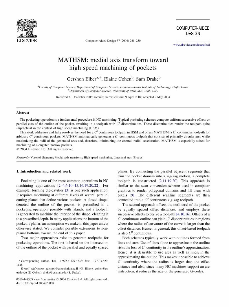
By definition, the MAT fully prescribes the maximal
circles one can fit into any location of the pocket to be
machined (see Fig. 1). Denote such circles as maximally
inscribed circles (MICs). The MAT provides excellent cues
to build a toolpath from successive MICs, following discrete
steps along the MAT. Since accelerations should be
minimized in HSM, by using MICs one is offered the best
complete circular motions that are possible at those pocket
locations. The MIC is the largest complete circle that fits
any pocket location, and hence the MIC prescribes the
motion that minimizes the radial accelerations among all
circular motions in that local neighborhood. By connecting
successive MICs using bi-tangent lines (see Fig. 2), one can
construct a full and complete toolpath that will machine the
entire pocket.
This short overview of the proposed toolpath generation
approach portrays the essence of this work. The toolpath is
constructed using successive MICs and small bi-tangent line
segments connect the successive MICs. Because, in practice,
successive MICs possess somewhat different radii and are
not necessarily centered along a straight line, each MIC could
be traversed less than or more than 3608 (see Fig. 2). Clearly,
the spacings of the MICs is closely related to the amount of
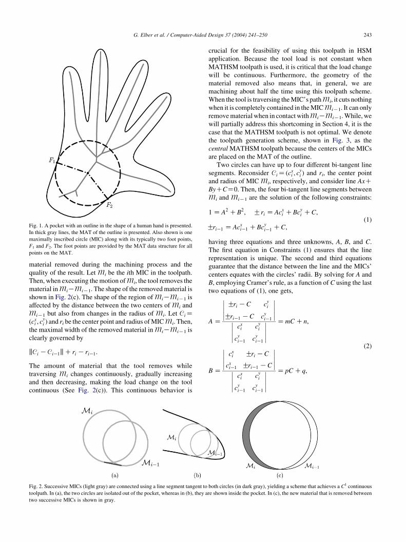
Fig. 1. A pocket with an outline in the shape of a human hand is presented.
In thick gray lines, the MAT of the outline is presented. Also shown is one
maximally inscribed circle (MIC) along with its typically two foot points,
F1 and F2. The foot points are provided by the MAT data structure for all
points on the MAT.
G. Elber et al. / Computer-Aided Design 37 (2004) 241–250 243
material removed during the machining process and the
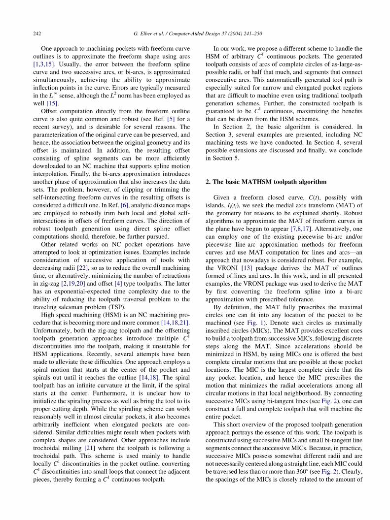
quality of the result. Let Mi be the ith MIC in the toolpath.
Then, when executing the motion of Mi, the tool removes the
material in MiKMiK1. The shape of the removed material is
shown in Fig. 2(c). The shape of the region of MiKMiK1 is
affected by the distance between the two centers of Mi and
MiK1 but also from changes in the radius of Mi. Let CiZðcx
i ; cyi Þ and ri be the center point and radius of MIC Mi. Then,
the maximal width of the removed material in MiKMiK1 is
clearly governed by
kCi KCiK1kCri KriK1:
The amount of material that the tool removes while
traversing Mi changes continuously, gradually increasing
and then decreasing, making the load change on the tool
continuous (See Fig. 2(c)). This continuous behavior is
Fig. 2. Successive MICs (light gray) are connected using a line segment tangent to
toolpath. In (a), the two circles are isolated out of the pocket, whereas in (b), they a
two successive MICs is shown in gray.
crucial for the feasibility of using this toolpath in HSM
application. Because the tool load is not constant when
MATHSM toolpath is used, it is critical that the load change
will be continuous. Furthermore, the geometry of the
material removed also means that, in general, we are
machining about half the time using this toolpath scheme.
When the tool is traversing the MIC’s path Mi, it cuts nothing
when it is completely contained in the MIC MiK1. It can only
remove material when in contact with MiKMiK1. While, we
will partially address this shortcoming in Section 4, it is the
case that the MATHSM toolpath is not optimal. We denote
the toolpath generation scheme, shown in Fig. 3, as the
central MATHSM toolpath because the centers of the MICs
are placed on the MAT of the outline.
Two circles can have up to four different bi-tangent line
segments. Reconsider CiZ ðcxi ; c
yi Þ and ri, the center point
and radius of MIC Mi, respectively, and consider line AxCByCCZ0. Then, the four bi-tangent line segments between
Mi and MiK1 are the solution of the following constraints:
1 Z A2 CB2; Gri Z Acxi CBc
yi CC;
GriK1 Z AcxiK1 CBc
yiK1 CC;
(1)
having three equations and three unknowns, A, B, and C.
The first equation in Constraints (1) ensures that the line
representation is unique. The second and third equations
guarantee that the distance between the line and the MICs’
centers equates with the circles’ radii. By solving for A and
B, employing Cramer’s rule, as a function of C using the last
two equations of (1), one gets,
A Z
Gri KC cyi
GriK1 KC cyiK1
�����
�����
cxi c
yi
cyiK1 c
yiK1
�����
�����
Z mC Cn;
B Z
cxi Gri KC
cxiK1 GriK1 KC
�����
�����
cxi c
yi
cyiK1 c
yiK1
�����
�����
Z pC Cq;
(2)
both circles (in dark gray), yielding a scheme that achieves a C1 continuous
re shown inside the pocket. In (c), the new material that is removed between
Fig. 3. A C1 continuous central toolpath for a flat end tool for a human hand is connected using left line segments, creating a toolpath with CW rotations (a) and
using right line segments, creating a toolpath with CCW rotations (b). (c) and (d) show the thumb of (a) and (b), respectively, scaled up.
G. Elber et al. / Computer-Aided Design 37 (2004) 241–250244
for some m, n, p, q2R. Substituting A and B into the first
constraints of (1), the solution of the quadratic equation is C.
Having C, one can resolve A and B using Eq. (2), completing
the solution.
Two equations in Constraints (1) have a sign (G) degree
of freedom, suggesting four possibilities overall. None-
theless, and noting that lines (A, B, C) and (KA, KB, KC)
are the same, all that is necessary is to differentiate the case
where both centers are on the same side of the line (external
bi-tangent) or both centers are on the opposite side of the
line (internal bi-tangent). Interested in external bi-tangents
only, we need only find the solution of Constraints (1) such
that both constraints share the same sign.
Assuming we would rather move in an always-clockwise
or always-counter-clockwise direction for all MICs and
throughout the toolpath, only the two external bi-tangents
are of interest. One can select either one of the two
external bi-tangents, corresponding to clockwise or
counter-clockwise toolpaths, two options that are shown in
Fig. 3(a) and (b), respectively. As can be seen by inspecting
Fig. 3, convex outline regions are better machined when
bi-tangent lines connect the successive MICs along the
convex edge. Yet, concave outline regions are better left
unconnected (connecting the successive MICs using their
other external bi-tangent), else gouging might occur. In
Section 4, we will consider a simple extension to this bi-
tangent line segment connection approach that will signifi-
cantly improve the quality of the finished machined outline,
for both convex and concave outline regions.
The MAT is a tree when no islands are introduced in the
outline, and shares the same genus with the pocket when
islands are present. In either case, each leaf of the MAT will
amount to one retraction in the toolpath. Since retractions
are expensive in HSM, we also consider an alternative
traversal of the MAT. Instead of placing the tool’s center
along the MAT, the tool will traverse the path while
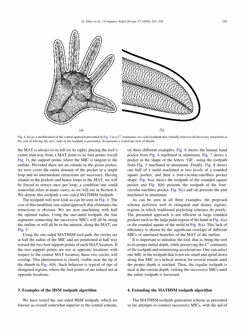
Fig. 4. In (a), a modification of the central approach presented in Fig. 3 as a C1 continuous one-sided toolpath that virtually removes all necessary retractions at
the cost of halving the arcs’ radii in the toolpath is presented. (b) presents a scaled up view of thumb.
G. Elber et al. / Computer-Aided Design 37 (2004) 241–250 245
the MAT is always to its left (or its right), placing the tool’s
center mid-way from a MAT point to its foot points (recall
Fig. 1), the support points where the MIC is tangent to the
outline. Provided there are no islands in the given pocket,
we now cover the entire domain of the pocket in a single
loop and no intermediate retractions are necessary. Having
islands in the pockets and hence loops in the MAT, we will
be forced to retract once per loop, a condition one could
somewhat relax in many cases, as we will see in Section 4.
We denote this toolpath a one-sided MATHSM toolpath.
The toolpath will now look as can be seen in Fig. 4. The
cost of this modified, one-sided approach that eliminates the
retractions is obvious. We are now machining with half
the optimal radius. Using the one-sided toolpath, the line
segments connecting the successive MICs will all be along
the outline or will all be in the interior, along the MAT; see
Fig. 5.
Using the one-sided MATHSM tool-path, the circles are
at half the radius of the MIC and are positioned at half way
toward the two foot support points of each MAT location. If
the two support points are not at opposite locations with
respect to the central MAT location, these two circles will
overlap. This phenomenon is clearly visible near the tip of
the thumb in Fig. 4(b). Such behavior is typical of tips of
elongated regions, where the foot points of are indeed not at
opposite locations.
3. Examples of the HSM toolpath algorithm
We have tested the one-sided HSM toolpath, which we
foresee as overall somewhat superior to the central scheme,
on three different examples. Fig. 6 shows the human hand
pocket from Fig. 4 machined in aluminum. Fig. 7 shows a
pocket in the shape of the letters ‘GE’, using the toolpath
from Fig. 5 machined in aluminum. Finally, Fig. 8 shows
one half of a mold machined at two levels of a rounded
square pocket, and then a four-circular-satellites pocket
shape. Fig. 8(a) shows the toolpath of the rounded square
pocket and Fig. 8(b) presents the toolpath of the four-
circular-satellites pocket. Fig. 8(c) and (d) presents the part
machined in aluminum.
As can be seen in all three examples, the proposed
scheme performs well in elongated and skinny regions,
regions in which traditional pocketing schemes do poorly.
The presented approach is not efficient in large rounded
pockets such as the large palm region of the hand in Fig. 4(a)
or the rounded square of the mold in Fig. 8(a). This lack of
efficiency is shown by the significant overlaps of different
MICs of unrelated branches of the MAT of the outline.
It is important to initialize the tool, that is, bring the tool
to its proper initial depth, while preserving the C1 continuity
of the toolpath and minimizing accelerations. One can select
one MIC in the toolpath that is not too small and spiral down
along that MIC in a helical motion for several rounds until
the proper depth is reached. Then, the regular toolpath is
used at the current depth, visiting the successive MICs until
the entire toolpath is traversed.
4. Extending the MATHSM toolpath algorithm
The MATHSM toolpath generation scheme as presented
so far attempts to connect successive MICs, with the aid of
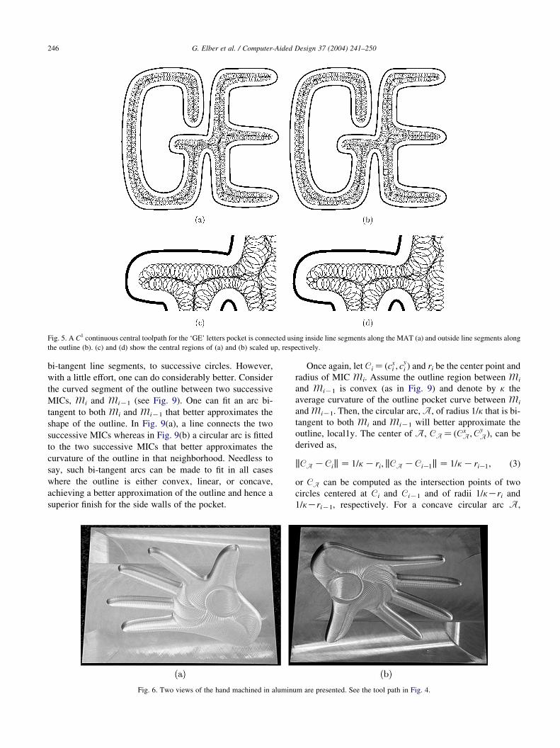
Fig. 5. A C1 continuous central toolpath for the ‘GE’ letters pocket is connected using inside line segments along the MAT (a) and outside line segments along
the outline (b). (c) and (d) show the central regions of (a) and (b) scaled up, respectively.
G. Elber et al. / Computer-Aided Design 37 (2004) 241–250246
bi-tangent line segments, to successive circles. However,
with a little effort, one can do considerably better. Consider
the curved segment of the outline between two successive
MICs, Mi and MiK1 (see Fig. 9). One can fit an arc bi-
tangent to both Mi and MiK1 that better approximates the
shape of the outline. In Fig. 9(a), a line connects the two
successive MICs whereas in Fig. 9(b) a circular arc is fitted
to the two successive MICs that better approximates the
curvature of the outline in that neighborhood. Needless to
say, such bi-tangent arcs can be made to fit in all cases
where the outline is either convex, linear, or concave,
achieving a better approximation of the outline and hence a
superior finish for the side walls of the pocket.
Fig. 6. Two views of the hand machined in aluminu
Once again, let Ci Z ðcxi ; c
yi Þ and ri be the center point and
radius of MIC Mi. Assume the outline region between Mi
and MiK1 is convex (as in Fig. 9) and denote by k the
average curvature of the outline pocket curve between Mi
and MiK1. Then, the circular arc, A, of radius 1/k that is bi-
tangent to both Mi and MiK1 will better approximate the
outline, local1y. The center of A, CA Z ðCxA;C
yAÞ; can be
derived as,
kCA KCik Z 1=k Kri; kCA KCiK1k Z 1=k KriK1; (3)
or CA can be computed as the intersection points of two
circles centered at Ci and CiK1 and of radii 1/kKri and
1/kKriK1, respectively. For a concave circular arc A,
m are presented. See the tool path in Fig. 4.
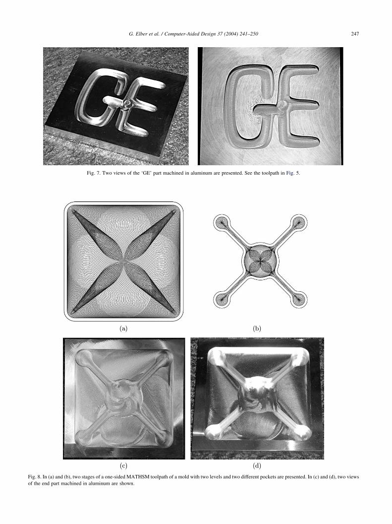
Fig. 7. Two views of the ‘GE’ part machined in aluminum are presented. See the toolpath in Fig. 5.
Fig. 8. In (a) and (b), two stages of a one-sided MATHSM toolpath of a mold with two levels and two different pockets are presented. In (c) and (d), two views
of the end part machined in aluminum are shown.
G. Elber et al. / Computer-Aided Design 37 (2004) 241–250 247
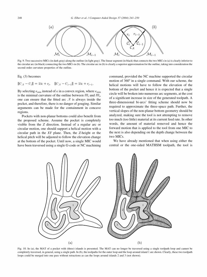
Fig. 9. Two successive MICs (in dark gray) along the outline (in light gray). The linear segment (in black) that connects the two MICs in (a) is clearly inferior to
the circular arc (in black) connecting the two MICs in (b). The circular arc in (b) is clearly a superior approximation for the outline, taking into consideration the
second order curvature properties of the outline.
G. Elber et al. / Computer-Aided Design 37 (2004) 241–250248
Eq. (3) becomes
kCA KCik Z 1=k Cri; kCA KCiK1k Z 1=k CriK1:
By selecting kmin instead of k in a convex region, where kmin
is the minimal curvature of the outline between Mi and Mi,
one can ensure that the fitted arc A is always inside the
pocket, and therefore, there is no danger of gouging. Similar
arguments can be made for the containment in concave
regions.
Pockets with non-planar bottoms could also benefit from
the proposed scheme. Assume the pocket is completely
visible from the Z direction. Instead of a regular arc or
circular motion, one should support a helical motion with a
circular path in the XY plane. Then, the Z-height or the
helical pitch will be adjusted to follow the elevation change
at the bottom of the pocket. Until now, a single MIC would
have been traversed using a single G-code or NC machining
Fig. 10. In (a), the MAT of a pocket with (three) islands is presented. The MA
completely traversed, in general, using a single path. In (b), the toolpaths for the ou
loops could be merged into one pass without retractions as can the loops around
command, provided the NC machine supported the circular
motion of 3608 in a single command. With our scheme, the
helical motions will have to follow the elevation of the
bottom of the pocket and hence it is expected that a single
circle will be broken into numerous arc segments, at the cost
of a significant increase in size of the generated toolpath. A
three-dimensional bi-arcs’ fitting scheme should now be
required to approximate the three-space path. Further, the
vertical slopes of the non-planar bottom geometry should be
analyzed, making sure the tool is not attempting to remove
too much (too little) material at its current feed rate. In other
words, the amount of material removed and hence the
forward motion that is applied to the tool from one MIC to
the next is also depending on the depth change between the
two MICs.
We have already mentioned that when using either the
central or the one-sided MATHSM toolpath, the tool is
T can no longer be traversed using a single toolpath loop and cannot be
ter loop and the loop around island 1 are shown. Clearly, these two toolpath
islands 2 and 3 (not shown).
G. Elber et al. / Computer-Aided Design 37 (2004) 241–250 249
removing material approximately half of the time. One
could somewhat alleviate this 50% deficiency by bringing
the tool more quickly to the next cutting position.
Traversing Mi, this goal could be achieved by either
increasing the feed rate while the tool is completely
contained in MiK1, or by shortening the length of the path
while completely inside MiK1, at the cost of higher
curvature arcs introduced into the toolpath.
In many cases, pockets are piecewise C1 continuous and
present corners. The stage of the computation of the MAT
can handle C1 discontinuities unaltered. Yet, clearly sharp
convex corners cannot be machined with a finite radius tool.
In traditional schemes, the minimal radius that can be
machined is governed by the tool radius. Here, and because
the tool is moving in circles, the minimal radius that can be
machined is also by the minimally allowed MIC, following
the maximal radial accelerations that are permitted.
When the one-sided MATHSM toolpath is used for
pockets with islands, the MAT is no longer a tree and
hence retractions are required. Since the toolpaths of the
different loops meet along shared MAT boundaries, one
can employ heuristics that connect different loops into a
larger toolpath, positioning the starting (and end) point(s)
of one loop at the seam with another loop, hence reducing
the number of retractions. Clearly not all retractions can be
removed using such a heuristic, but this number, bounded
from above by the number of islands in the pocket, can be
made even smaller in practice. Fig. 10 again shows the
hand pocket, this time with three interior islands. The MAT
can no longer be traversed using a toolpath of a single loop.
Yet, the presented loops, the outer loop and the loop
around island 1, can clearly be merged into one toolpath as
can the two loops around islands 2 and 3. (They are not
shown.)
When the radius of the MIC is changing rapidly, a
redundant front can be formed in the toolpath. This effect
can be seen, for example, near the bases of the five fingers,
in Figs. 3 and 4. The reason for this behavior can be found in
the large change of radius in the MIC as the MAT and the
toolpath traverse the palm into one of the fingers. In order
for the toolpath to enter the finger, its MICs’ radii
must be significantly reduced. The radii of the MICs is
decreased almost as fast as the centers of the MICs are
moving forward, creating a front that is almost standing still.
Equally critical is the fact that the material removal rate at
the neighborhood of this front is minimal. One can clearly
alleviate this toolpath redundancy by purging MICs that
remove little or no material, near the front. By computing
the amount of material being removed between two
successive MICs (see Fig. 2(c)), one can purge away
intermediate MICs that contribute below a certain threshold.
Alternatively and based on the changes in the radii of the
MICs, one can modify the forward steps between two
successive MICs to ensure a constant amount of material
removal or constant tool load.
5. Conclusion and future work
In this paper, we have introduced a new scheme for
toolpath generation of pockets, with typically freeform
outlines, toward HSM. The generated toolpath is C1
continuous. Further, the central MATHSM toolpath opti-
mizes the radial acceleration exerted on the machining tool,
whereas the one-side MATHSM toolpath minimizes the
number of retractions-two features that are of extreme
importance in HSM.
The MATHSM toolpath is inefficient in large rounded
pocket regions, such as the palm region of the hand
(Fig. 6(a)) or the rounded square shape of the mechanical
mold’s pocket (Fig. 8(a)).
One can attempt more global optimization schemes and
detect cases where Mi cuts nothing, not due to MiK1, but
because of previous machining operations, from different
branches of the MAT of the shape. Nevertheless, even with
such feasible yet complex optimization, we expect that the
toolpath scheme presented in the work augments more
standard approaches in regions that are long and narrow,
regions where the MATHSM performs very well and more
standard approaches lead to C1 discontinuities, changes in
accelerations, and multiple retractions. We foresee a global
analysis scheme that will examine the geometry of a given
pocket and optimize and split the work between different
toolpath generation techniques, using the MATHSM
scheme in long and narrow pocket regions and traditional
schemes in almost circular pocket regions.
Acknowledgements
The research was supported in part by ARO (DAAD19-
01-1-0013) and the Fund for Promotion of Research at the
Technion, Haifa, Israel. All opinions, findings, conclusions
or recommendations expressed in this document are those of
the authors and do not necessarily reflect the views of the
sponsoring agencies.
References
[1] Ahn YJ, Kim HO, Lee KY. G1 arc spline approximation of quadratic
Bezier curves. Comput Aid Des 1998;30(8):615–20.
[2] Arkin EM, Held M, Smith CL. Optimization problems related to
zigzag pocket machining. Algorithmica 2000;26(2):197–236.
[3] Choi BK, Kim BH. Die-cavity pocketing via cutting simulation.
Comput Aid Des 1997;29(12):837–46.
[4] Chou JJ. NC milling machine toolpath generation for regions bounded
by free form curves and surfaces. PhD Thesis. Department of
Computer Science, University of Utah; April 1989.
[5] Elber G, Lee IK, Kim MS. Comparing offset curve approximation
methods. CG A 1997;17(3):62–71.
[6] Elber G. Trimming local and global self-intersections in offset curves
using distance maps The Proceedings of the Tenth IMA Conference
on the Mathematics of Surfaces, University of Leeds 2003 pp. 213–
222. LLCS2768.
G. Elber et al. / Computer-Aided Design 37 (2004) 241–250250
[7] Farouki RT, Ramamurthy R. Voronoi diagram and medial axis
algorithm for planar domain with curves boundaries I. Theor Found
J Comput Appl Algorithms 1999;102:119–41.
[8] Farouki RT, Ramamurthy R. Voronoi diagram and medial axis
algorithm for planar domain with curves boundaries II. Theor Found
J Comput Appl Algorithms 1999;102:253–77.
[9] Foley JD, van Dam A, Feiner SK, Hughes JF. Fundamentals of
interactive computer graphics, 2nd ed. Reading, MA: Addison-
Wesley; 1990.
[10] Hansen A, Arbab F. An algorithm for generating NC tool paths for
arbitrarily shaped pockets with islands. ACM Trans Graph 1992;
11(2):152–82.
[11] Held M. A geometry-based investigation of the tool path generation
for zigzag pocket machining. Visual Comput 1991;7(5–6):296–308.
[12] Held M. Pocket machining based on contour-parallel tool paths
generated by means of proximity maps. Comput Aid Des 1994;26(3):
189–203.
[13] Held M. VRONI: an engineering approach to the reliable and efficient
computation of Voronoi diagrams of points and line segments.
Comput. Geom. Theory and Appl. 2001;18(2):95–123.
[14] Lee E. Contour offset approach to spiral toolpath generation with
constant scallop height. Comput Aid Des 2003;35(6):511–8.
[15] Ong CJ, Wong YS, Loh HT, Hong XG. An optimization approach for
biarc curve-fitting of B-spline curves. Comput Aid Des 1996;28(12):
951–9.
[16] Persson H. NC machining of arbitrary shaped pockets. Comput Aid
Des 1978;10(3):169–74.
[17] Ramanathan M, Gurumoorthy B. Constructing medial axis transform
of planar domains with curved boundaries. Comput Aid Des 2003;
21(6):371–8.
[18] Spiral high speed machining. Cimatron. http://www.cimatron.com.
[19] Tang K, Chou SY, Chen LL. An algorithm for reducing tool
retractions in zigzag pocket machining. Comput Aid Des 1998;30(2):
123–9.
[20] Tang K, Joneja A. Traversing the machining graph of a pocket.
Comput Aid Des 2003;35(11):1023–40.
[21] Trochoidal high speed machining. Delcam. http://www.delcam.com,
http://www.mmsonline.com.
[22] Veeramani D, Gau YS. Selection of an optimal set of cutting-tool
sizes for 2 1/2 D pocket machining. Comput Aid Des 1997;29(12):
869–77.
Gershon Elber is an associate professor in the
Computer Science Department, Technion,
Israel. His research interests span computer
aided geometric designs and computer
graphics. Elber received a BS in computer
engineering and an MS in computer science
from the Technion, Israel in 1986 and 1987,
respectively, and a PhD in computer science
from the University of Utah, USA, in 1992. He
is a member of the ACM and IEEE. Elber
serves on the editorial board of the Computer
Aided Design and Computer Graphics Forum journals and has served in
many conference program committees including Solid Modeling, Pacific
Graphics, Computer Graphics International, and Siggraph. Prof. Elber is
also one of the two paper chairs of Solid Modeling 2003 and Solid
Modeling 2004.