Embed Size (px)
Citation preview

MAURER MSM® – the Innovative Sliding Material
MAURER MSM® Sliding Bearings
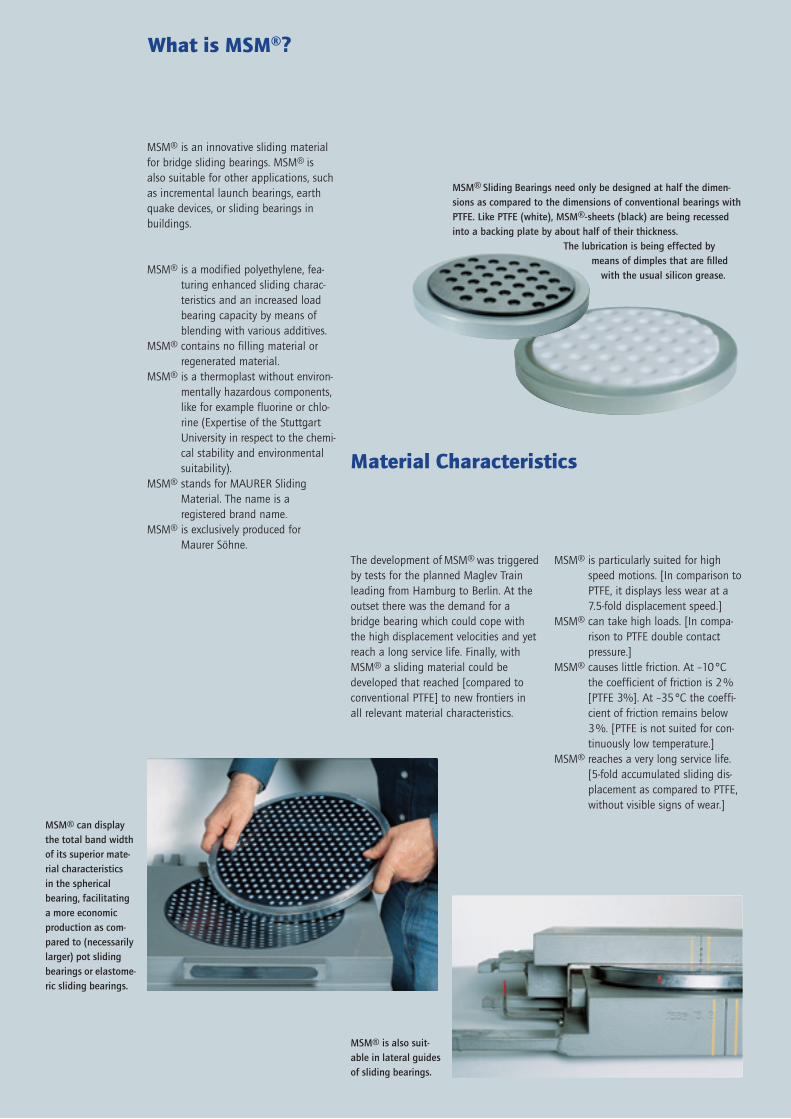
MSM® is an innovative sliding material for bridge sliding bearings. MSM® is also suitable for other applications, such as incremental launch bearings, earth quake devices, or sliding bearings in buildings.
MSM® is a modified polyethylene, fea-turing enhanced sliding charac-teristics and an increased load bearing capacity by means of blending with various additives.
MSM® contains no filling material or regenerated material.
MSM® is a thermoplast without environ-mentally hazardous components, like for example fluorine or chlo-rine (Expertise of the Stuttgart University in respect to the chemi-cal stability and environmental suitability).
MSM® stands for MAURER Sliding Material. The name is a registered brand name.
MSM® is exclusively produced for Maurer Söhne.
What is MSM®?
The development of MSM® was triggered by tests for the planned Maglev Train leading from Hamburg to Berlin. At the outset there was the demand for a bridge bearing which could cope with the high displacement velocities and yet reach a long service life. Finally, with MSM® a sliding material could be developed that reached [compared to conventional PTFE] to new frontiers in all relevant material characteristics.
Material Characteristics
MSM® can display the total band width of its superior mate-rial characteristics in the spherical bearing, facilitating a more economic production as com-pared to (necessarily larger) pot sliding bearings or elastome-ric sliding bearings.
MSM® Sliding Bearings need only be designed at half the dimen-sions as compared to the dimensions of conventional bearings with PTFE. Like PTFE (white), MSM®-sheets (black) are being recessed into a backing plate by about half of their thickness.
The lubrication is being effected by means of dimples that are filled
with the usual silicon grease.
MSM® is also suit-able in lateral guides of sliding bearings.
MSM® is particularly suited for high speed motions. [In comparison to PTFE, it displays less wear at a 7.5-fold displacement speed.]
MSM® can take high loads. [In compa-rison to PTFE double contact pressure.]
MSM® causes little friction. At –10°C the coefficient of friction is 2% [PTFE 3%]. At –35°C the coeffi-cient of friction remains below 3%. [PTFE is not suited for con-tinuously low temperature.]
MSM® reaches a very long service life.[5-fold accumulated sliding dis-placement as compared to PTFE, without visible signs of wear.]

MSM® employs enormous savings potential and new possibilities in bridge construction.
Unmatched at high performance requirementsAt extreme strains (e.g. high speed motions, high contact pressures, high accumulated sliding displacements, low temperatures), MSM® is the only sliding material that matches all per-formance requirements. Thus, MSM® fills a gap in particular in high speed railway bridges, soft structures and bridges with high traffic loads or long span widths.
Smaller dimensions Due to the double as high design contact pressure that MSM® employs in comparison to PTFE, MSM® Spheri-cal Bearings need only be dimensioned half their size.
Spherical Bearings instead of Pot BearingsBecause the MSM® Spherical Bearing is smaller, in many cases it is also more economical to manufacture as a (necessarily larger) sliding pot bearing or sliding elastomeric bearing.
More economical construction methodThe smaller dimensions facilitate more slender and thus more econo-mical constructions due to enormous savings in material.
More architectonical degrees of freedomSmaller bearings enable architecto-nical degrees of freedom.
40-fold increased service life In considering all material characte-ristics and advantages, compared to PTFE MSM® employs a minimum 40-fold increased life time. This leads to considerably reduced maintenance costs, and thus in long term to enor-mous cost savings.
Conclusion: Compared to PTFE, the new sliding material MSM® displays many advantages, and even if not taking advantage of its additional performance characteristics, MSM® is neutral in respect to costs.
What can MSM® achieve?
Due to the high performance require-ments which are met by MSM®, it is employed in the following projects (examples):
Allianz Arena Munich Subway Moscow Tejo-Bridge Lisbon Incremental Launch Bearings Viaduct Millau Suspension Monorail Wuppertal Transrapid (Maglev)-Testtrack Lathen Canal Bridge Schwarzach “Sarkophag“ Tchernobyl High Speed Railways AVE in Spain TGV in France
References
Tejo Bridge 25th April at Lisbon/Portugal: MSM® Spherical Bearings for 10 km sliding path/year at 15 mm/s
Viaduct Millau/France: Incremental launch system, 64 synchronically controlled MSM® shifting devices
Suspension Monorail at Wuppertal/Germany: Test of MSM®-elements for 7km sliding path/year at 30 mm/s
Allianz Arena Munich/Germany: MSM® Spherical Bearings to support the roof structure
REFE
R, E
.P.
Hor
st-P
eter
Kra
use
Ei
ffag
e TP
ALL
IAN
Z A
rena
Mün
chen
Sta
dion
Gm
bH

In respect to its material characteristics, MSM® was thoroughly tested at the State Material Testing Institute of the Stuttgart University (MPA). The test arrangement was identical as it is required for sliding friction tests accor-ding to EN 1337 for the qualification of components for structural bearings. So far, the long term tests did not bring about any signs of wear. The data dis-played on these 2 pages thus describe the performance within the test range. The limits of MSM® could however not yet be reached.
To cite the conclusion of MPA Stuttgart:“To summarize, it can be noted that, based on the regulations for the use of white PTFE to be used as component in structural bearings, no reservations can be made for the use of the Maurer Sliding Material MSM®. In addition, MSM® can cover performance require-ments in areas where PTFE has obviously failed and that therefore are not con-sidered in the regulations. Even under relatively high strain (contact pressure p to a maximum of 200 N/mm2 – static load, respectively 60 N/mm2 – dynamic load, speed v up to 15 mm/s), only limited deformations due to creep and relatively low coefficients of friction can be noted. Further, practically no signs of wear or other relevant damages could be detected in the contact area.”
MSM® at test
Figure A: MSM®-sheets in long term sliding test (with dimples)
Figure B: MSM®-strips in long term sliding test (without dimples)
In contrast to this, the photos of the PTFE clearly show abrasion of the material. These photos were taken also at the MPA Stuttgart, after completion of the 10-km-long term test according to EN 1337-2.
After completing the 10 km test at the MPA Stuttgart, it can clearly be noted that the MSM®-strips and the stainless steel sheet show no signs of abrasion.
Photos of an MSM®-sheet (left) and a stainless steel sheet (right), taken after opening the test bearing and after completion of the 50 km test. Little scars can be found (also at the bottom of the dimples), but no wear.
0,07
0,06
0,05
0,04
0,03
0,02
0,01
0,00
0 15.000 30.000 45.000 60.000
Total sliding path stot in m (v = 15 mm/s; p = 60 N/mm2)
Coef
ficie
nt o
f fric
tion
µ max
,T
(v =
0,4
mm
/s;
p =
30
N/
mm
2 )
T in °C
–35
–20
–10
0
+21+40
Limit values for PTFE acc. to EN 1337-2=
0,20
0,16
0,12
0,08
0,04
0,00
0 3.000 6.000 9.000 12.000
Total sliding path stot in m(v = 15 mm/s; p = 60 N/mm2)
Coef
ficie
nt o
f fric
tion
µ max
,T
(v =
0,4
mm
/s;
p =
30
N/
mm
2 )
T in °C
–35
–20
–10
0+21+40
Limit values for PTFE acc. to EN 1337-2=

The tests that were conducted comprised long and short term tests under static load as well as sliding tests. In all tests, the constant components (i.e. mating partners) to be applied in the test bea-rings were the stainless steel sheet and silicon grease in bridge bearing quality.
Figure ASubject of tests were MSM®-sheets ex-posed to a long term sliding test. Figure A shows that the coefficient of friction of MSM® remains under the relevant limits of PTFE, which are defined in EN 1337-2. Even after a total accumulated sliding displacement of 50 km MSM® exceeds the relevant value of PTFE only to a very small degree. In this test, the accumulated sliding displacement was taken at room temperature at an average contact pressure of 60 N/mm2 and a constant sliding speed of 15 mm/s. (For the PTFE tests according to EN 1337-2, a contact pressure of 30 N/mm2 and a sliding speed of 2 mm/s has to be applied.) As it is usual in PTFE tests, the coefficients of friction of MSM® were determined as a function of temperature, at a contact pressure of 30 N/mm2 and a sliding speed of 0.4 mm/s.Figure A also shows that MSM® is also suitable for constant low temperatures of –35°C. From this it can be concluded that MSM® would also withstand short term temperatures of as low as –50°C. In contrast, PTFE is not suited for a long term use at temperatures of –35°C.
Figure BTested were MSM®-strips with a one-time initial lubrication. The tests were conducted in analogy to A, with higher contact pressures and sliding velocities to be applied for MSM® as compared to PTFE. Due to the fact that the guides reach lower accumulated sliding dis-placements, MSM® was exposed to only a fifth of the earlier accumulated sliding displacement of 50 km: after 10 km, the coefficient of friction of MSM® still is below the relevant coefficient of friction of PTFE after 2 km.
Figure CThe figure displays the decrease of the sliding clearance at the described long term test. It can clearly be seen that with the exception of the initial elasto-plastic deformation, the sliding clearance almost does not decrease further over
Figure DThe statical load tests show an initial elasto-plastic deformation as a function of contact pressure, to be followed by a long term creep that subsides after app. 48 hours even under the characteristic contact pressure of 180 N/mm2 (dark blue graph). PTFE shows a similar long term behaviour at a contact pressure of
the total sliding displacement. The decrease of the sliding clearance can be owed to the deformation of lubrication dimples and the formation of a bulbous protrusion. However, the stable graph shows that MSM® is not subject to wear.
90 N/mm2 (red graph). Exposed to the same contact pressure, the deformation behaviour of MSM® and PTFE is similar. That is, in using MSM®, the balancing bedding behaviour that we know from PTFE does not go lost (light blue graph and red graph in comparison).
Figure C: Wear in the same long term test as in Figure A
Figure D: Statical long term deformation test with constant contact pressure
���
���
���
���
����� ������������ �������������� � ������������� � ������������� � ����������
�������������������������∑�������
������������
������������
�
����������
������������������������������������������������
������� �����������������������������������������
���
���
���
���
���
���
���
���� ���� �� �� ��
������������������������������������������������������������
������ ��������������
������ ������ ��������
������ ������ ��������
����
�����������
����
������������
���
h
s = f (v, t)
D
p
tp

The characteristic values of the per-missible contact pressure of MSM® are the double values of those of PTFE, and for constant loads even the 6 fold values. The coefficients of friction of MSM®-sheets with dimples as a function of the contact pressure can be calculated according to the following formula (PTFE-values in brackets).
The thus calculated values reflect the performance in Germany at a frequently occurring low temperature of –10 °C. Should lower temperatures be reached or they are only rarely that low, analogous values can be derived from Figure E.
Design and Construction
It must be emphasized again that the coefficients of friction were taken at the extremely high sliding speed of 15 mm/s, and also considering the enormous accumulated sliding displacement of 50 km.
For MSM®-strips with initial lubrication in guides a coefficient of friction of 10 % was formulated, independent of the contact pressure. Also this coefficient of friction holds for extreme sliding speed of 15 mm/s, a sliding displace-ment of 10 km, and frequent low temperatures of –10°C. For PTFE, the regulations formulate a coefficient of friction of 8%. However, as Figure B shows, this value only holds for sliding displacements of 2 km and sliding speed of 2 mm/s. At these conditions, the relevant MSM®-value remains below 5%.
Permissible Contact Pressures
MAURER MSM® Spherical Bearings enjoy the General Approval of the “Deutsches Institut für Bautechnik“ (Approval No. Z-16.4-436). Third party monitoring is carried out by the MPA Stuttgart as well as being supervised within the stipulations of the RAL Quality Association. Thus the products are en-titled to bear the Ü conformity mark as well as the RAL conformity mark.The German General Approval is based on the specifications of the European Norm EN 1337-2 for sliding elements in structural bearings. Presently Euro-pean Approval is being applied (Ref.No. 8.03.01-0005/03). After being granted the European Approval, the CE conformity mark can be borne, thus being entitled to an unlimited trade in the European market.
In the General Approval, the suitability of MSM® is highlighted: “…suitable in particular for soft structures with considerable and frequent deflections due to traffic loads, for structures with fast occurring sliding movements of the bearings, like for example for bridges for high speed railways, and for regions with continuously low temperatures“. MSM® is patented. The required detailed information is placed with the Deutsches Institut für Bautechnik and with the MPA Stuttgart.
Characteristic values of the permissible contact pressures of MSM®
Figure E: Coefficients of friction of MSM®-sheets with dimples as a function of contact pressure
MAURER MSM® Spherical Bearing with guides: concave lower part (above) and with inserted calotte (below).
0,08 ≥ µ = 15 + p ≥ 0,021,6
(0,08 ≥ µ = 10 + p ≥ 0,03)1,2
Contact Pressure in N/mm2
Coef
ficie
nt o
f fric
tion
µ max
,T [
%]
T in °C
0
1
2
3
4
5
6
7
8
9
0 10 20 30 40 50 60 70
µ = 1,6 / (15 + p)
–35
–20–10
0+21+40
Char
act.
perm
issi
ble
pres
sure
fk i
n N
/m
m2
Main sliding surfaceconstant and variable loads
180 Guides
variable loads
Guidesconstant loads,
loads from temperature, creepand shrinkage
60
Partial safety coefficient γm acc. to EN 1990 1,4

FRdu= Aco× ƒcd × ≤ 3,0 × Ac0× ƒcdAc1
Ac0
ƒcd= α × ƒcd × = 0,85 × ƒck
γc
ƒck
1,5
Bearing Dimensions
Due to the high design contact pressure of MSM®, bridge bearings can be designed in a compact way and thus economical in particular when spherical bearings can be employed and the adjacent structural members can transfer the high contact pressure. This is usually the case with steel super-structures and high strength concrete. In using intermediate elements like steel plates, high strength grouting or basements as well as by means of special reinforcements, this effect can also be achieved with concretes of lower grade. This way, the proof of partial area pressure as requested in DIN report 102:2003 has to be conducted according to the following formula.
The following tables reflect the guide values for the main dimensions of MAURER MSM® Spherical Bearings as a function of the relevant concrete grade.
(for the basic combination of actions and under long term impact)
Distribution of the pressure, to serve the proof of partial area pressure
Assumptions:tan ϕ ≤ 0,01 ey = ±10 mm
Concrete grade C35/45MSM®
BearingType
Load H Bu Lu BGL ex = ±50 mm ex = ±100 mm ex = ±150 mmV*
*Design value of the basic combination of actions acc. to EN 1990
LGL Gew. LGL Gew. LGL Gew.kN mm mm mm mm kg mm kg mm kg
KGa – 1 1000 105 150 190 330 35 440 45 550 55KGa – 5 5000 115 310 340 480 100 590 115 700 130KGa – 10 10000 130 430 460 600 210 710 230 820 250KGa – 25 25000 165 680 730 850 650 960 690 1070 730KGa – 50 50000 250 950 1000 1120 1800 1230 1920 1340 2040
Concrete grade C40/50MSM®
BearingType
Load H Bu Lu BGL ex = ±50 mm ex = ±100 mm ex = ±150 mmV* L GL Gew. LGL Gew. LGL Gew.
kN mm mm mm mm kg mm kg mm kgKGa – 1 1000 105 150 190 330 35 440 45 550 55KGa – 5 5000 115 290 320 460 90 570 105 680 120KGa – 10 10000 130 400 430 570 180 680 200 790 220KGa – 25 25000 160 630 680 800 600 910 640 1020 680KGa – 50 50000 230 890 940 1060 1400 1170 1500 1280 1600
b1Ac0
Ac1b2 ≤ 3b1
h ≥
b 2 –
b 1
d 1
d 2 ≤ 3d 1
axis of load direction

Low Friction.
High Pressure.
High Speed Motions.
Long Life.
MSM® is a newly-developed, innovative sliding material. In bridge construction, MAURER MSM® Sliding Bearings outperform conventional PTFE bearings, employing at least the following features:
Facilitates 7.5-fold speed Twice the load capacity 5-fold increase in total sliding distances Coefficient of friction less than 3 %,
even at temperatures below –35°C
This all adds up to at least a 40-fold increase in service life, smaller dimensions and a more economical construction.
Maurer Söhne Head OfficeFrankfurter Ring 193, 80807 Munich/GermanyP. O. Box 44 01 45, 80750 Munich/GermanyPhone +49/89/3 23 94–0Fax +49/89/3 23 94–3 06e-mail [email protected] www.maurer-soehne.de
Maurer Söhne Branch OfficeZum Holzplatz 2, 44536 Lünen/GermanyP. O. Box 63 40, 44520 Lünen/GermanyPhone +49/2 31/4 34 01-0Fax +49/2 31/4 34 01-11
Maurer Söhne Subsidiary PlantKamenzer Str. 4-6, 02992 Bernsdorf/GermanyP. O. Box 55, 02992 Bernsdorf/GermanyPhone +49/3 57 23/2 37-0Fax +49/3 57 23/2 37-20
MAURER MSM® Sliding Bearings
Transrapid-project:Airport Munich to Centre
Phot
ogra
ph u
nder
frie
ndly
app
rova
l by
Tran
srap
id In
tern
atio
nal
BA41
2GB.
5000
.08.
03


![Controllable Sliding Bearings and Controllable Lubrication ... · Review Controllable Sliding Bearings and Controllable ... or evolutionary [5], but it does not change the fact that](https://img.pdfslide.net/doc/110x75/5fc50df11ca4e1756528a85b/controllable-sliding-bearings-and-controllable-lubrication-review-controllable.jpg)


![[Eng] dry composite sliding bearings producer blind profile](https://img.pdfslide.net/doc/110x75/558bd091d8b42aca448b45f4/eng-dry-composite-sliding-bearings-producer-blind-profile.jpg)