Embed Size (px)
Citation preview
- 1 -
Max Charge MC-612Installation AndOperation Manual
I. IntroductionThe microprocessor-controlled Max Charge MC-612 is the most advanced regulator available. The MC-612lets you choose from a variety of selectable preset programs to best suit your charging needs. Its UniversalFactory Program allows you to connect the MC-612 to your alternator right out of the box. Six additional pre-set programs support most popular battery types, including standard and deep-cycle flooded batteries, AGM,gel, and Optima (spiral wound) technologies, as well as special settings for systems supplying halogen light-ing. An easy-to-use magnetic reed switch delivers quick, precise regulator adjustment. Should your charg-ing system require individualized adjustment, the MC-612 provides additional advanced user-defined pro-gramming options.
When used with optional alternator and battery temperature sensors, the MC-612 automatically monitorsambient alternator and battery temperatures and compensates by adjusting field output to match conditions.Alarm outputs connect to audible or visual alarms to provide warnings of dangerous system conditions.
II. Safety ConsiderationsBefore installing your MC-612 marine regulator, please take a moment to consider these guidelines for saferegulator installation. Failure to work safely could result in injury or damage to your electrical system.
1. Always disconnect your battery banks and ensure that switches are “OFF” prior to installing your regulator.
2. Remove loose-fitting clothing or jewelry, which could become entangled in your motor or other machinery.
3. Wear ANSI-approved safety glasses.
4. DO NOT attempt to modify the regulator. Alterations could result in damage to your charging system, and will voidyour warranty.
5. Do not attempt installation if tired or fatigued.
6. Ensure the engine has cooled before initiating installation.
7. Do not attempt installation while using alcohol or medication that could impair your judgment or reaction time.
8. Always use the right tool for the job. Improper tool use may damage regulator or your boat, and could result inpersonal injury.
9. Take time to read the manual. Equipment damage and possible injuries may result from an incomplete under-standing of the installation and operation of the MC-612 regulator. If you are unfamiliar with marine electrical sys-tems, consult with a licensed marine electrician.
I. Introduction ........................................................1II. Safety Considerations ........................................1III. Installation Guide............................................2-5IV. Optional Wiring Connections ........................5-6V. Regulator Operation ..........................................7VI. Regulator Display Modes ..................................8
VII. Programming Modes ....................................9-11VIII. System Troubleshooting............................12-13IIX. Suggested Wiring Configurations..............14-15Express Installation Instructions ..........................16Warranty....................................................................16
TABLE OF CONTENTS
- 2 -
III. Installation GuideThe following information is intended to provide the installer with the basic information required to com-plete installation. This section of the installation manual will deal with mounting, wiring connections andbasic programming for battery type. Additional informationregarding advanced programming adjustments and trou-bleshooting are addressed later in the manual.
CautionThe following instructions are intended for use by experienced marine electrical installers. Ifyou are not experienced at installing electrical system components, we recommend the use of aqualified marine electrical technician.
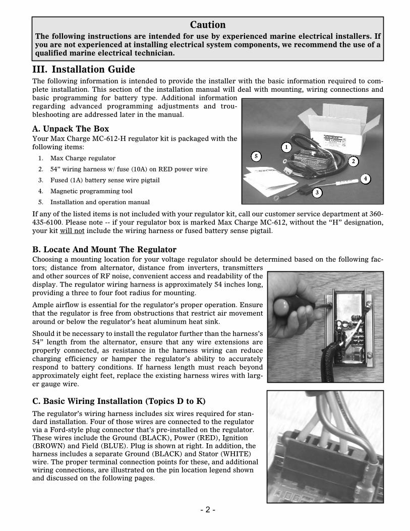
A. Unpack The BoxYour Max Charge MC-612-H regulator kit is packaged with thefollowing items:
1. Max Charge regulator
2. 54” wiring harness w/ fuse (10A) on RED power wire
3. Fused (1A) battery sense wire pigtail
4. Magnetic programming tool
5. Installation and operation manual
If any of the listed items is not included with your regulator kit, call our customer service department at 360-435-6100. Please note -- if your regulator box is marked Max Charge MC-612, without the “H” designation,your kit will not include the wiring harness or fused battery sense pigtail.
1
2
3
4
5
B. Locate And Mount The RegulatorChoosing a mounting location for your voltage regulator should be determined based on the following fac-tors; distance from alternator, distance from inverters, transmittersand other sources of RF noise, convenient access and readability of thedisplay. The regulator wiring harness is approximately 54 inches long,providing a three to four foot radius for mounting.
Ample airflow is essential for the regulator’s proper operation. Ensurethat the regulator is free from obstructions that restrict air movementaround or below the regulator’s heat aluminum heat sink.
Should it be necessary to install the regulator further than the harness’s54” length from the alternator, ensure that any wire extensions areproperly connected, as resistance in the harness wiring can reducecharging efficiency or hamper the regulator’s ability to accuratelyrespond to battery conditions. If harness length must reach beyondapproximately eight feet, replace the existing harness wires with larg-er gauge wire.
C. Basic Wiring Installation (Topics D to K)The regulator’s wiring harness includes six wires required for stan-dard installation. Four of those wires are connected to the regulatorvia a Ford-style plug connector that’s pre-installed on the regulator.These wires include the Ground (BLACK), Power (RED), Ignition(BROWN) and Field (BLUE). Plug is shown at right. In addition, theharness includes a separate Ground (BLACK) and Stator (WHITE)wire. The proper terminal connection points for these, and additionalwiring connections, are illustrated on the pin location legend shownand discussed on the following pages.
- 3 -
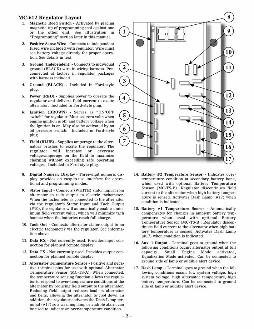
MC-612 Regulator Layout1. Magnetic Reed Switch - Activated by placing
magnetic tip of programming tool against oneor the other end. See illustration in“Programming” section later in this manual.
2. Positive Sense Wire - Connects to independentfused wire included with regulator. Wire mustsee battery voltage directly for proper opera-tion. See details in text.
3. Ground (Independent) - Connects to individualground (BLACK) wire in wiring harness. Pre-connected at factory in regulator packageswith harness included.
4. Ground (BLACK) - Included in Ford-styleplug.
5. Power (RED) - Supplies power to operate theregulator and delivers field current to excitealternator. Included in Ford-style plug.
6. Ignition (BROWN) - Serves as “ON/OFFswitch” for regulator. Must see zero volts whenengine ignition is off and battery voltage whenthe ignition is on. May also be activated by anoil pressure switch. Included in Ford-styleplug.
7. Field (BLUE) - Supplies amperage to the alter-nators brushes to excite the regulator. Theregulator will increase or decreasevoltage/amperage on the field to maximizecharging without exceeding safe operatingvoltages. Included in Ford-style plug.
8. Digital Numeric Display - Three-digit numeric dis-play provides an easy-to-use interface for opera-tional and programming modes.
9. Stator Input - Connects (WHITE) stator input fromalternator to tach output to electric tachometer.When the tachometer is connected to the alternatorvia the regulator’s Stator Input and Tach Output(#10), the regulator will automatically enable a min-imum field current value, which will minimize tachbounce when the batteries reach full charge.
10. Tach Out - Connects alternator stator output to anelectric tachometer via the regulator. See informa-tion above.
11. Data RX - Not currently used. Provides input con-nection for planned remote display.
12. Data TX - Not currently used. Provides output con-nection for planned remote display.
13. Alternator Temperature Sensor - Positive and nega-tive terminal pins for use with optional AlternatorTemperature Sensor (MC-TS-A). When connected,the temperature sensing function allows the regula-tor to respond to over-temperature conditions at thealternator by reducing field output to the alternator.Reducing field output reduces load on alternatorand belts, allowing the alternator to cool down. Inaddition, the regulator activates the Dash Lamp ter-minal (#17) so a warning lamp or audible alarm canbe used to indicate an over-temperature condition.
14. Battery #2 Temperature Sensor - Indicates over-temperature condition at secondary battery bank,when used with optional Battery TemperatureSensor (MC-TS-B). Regulator discontinues fieldcurrent to the alternator when high battery temper-ature is sensed. Activates Dash Lamp (#17) whencondition is indicated.
15. Battery #1 Temperature Sensor - Automaticallycompensates for changes in ambient battery tem-perature when used with optional BatteryTemperature Sensor (MC-TS-B). Regulator discon-tinues field current to the alternator when high bat-tery temperature is sensed. Activates Dash Lamp(#17) when condition is indicated.
16. Aux. 1 Output - Terminal goes to ground when thefollowing conditions occur: alternator output at fullcapacity, Small Engine Mode activated,Equalization Mode activated. Can be connected toground side of lamp or audible alert device.
17. Dash Lamp - Terminal goes to ground when the fol-lowing conditions occur: low system voltage, highsystem voltage, high alternator temperature, highbattery temperature. Can be connected to groundside of lamp or audible alert device.
- 4 -
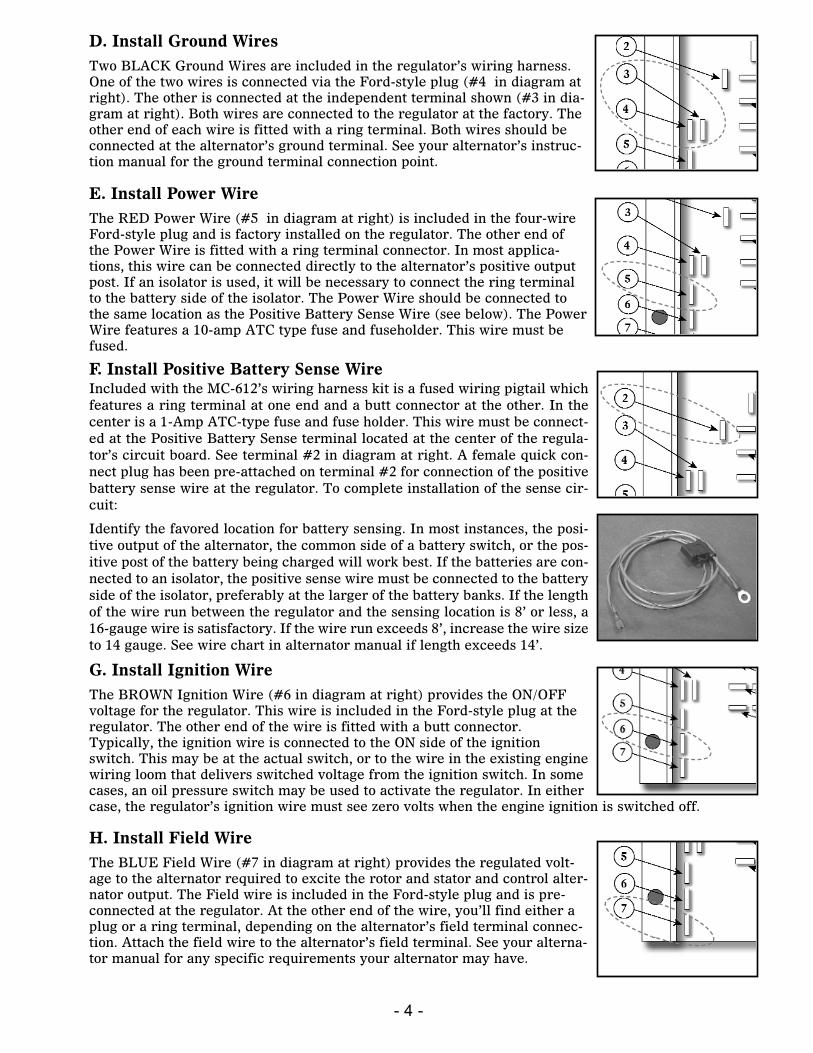
F. Install Positive Battery Sense WireIncluded with the MC-612’s wiring harness kit is a fused wiring pigtail whichfeatures a ring terminal at one end and a butt connector at the other. In thecenter is a 1-Amp ATC-type fuse and fuse holder. This wire must be connect-ed at the Positive Battery Sense terminal located at the center of the regula-tor’s circuit board. See terminal #2 in diagram at right. A female quick con-nect plug has been pre-attached on terminal #2 for connection of the positivebattery sense wire at the regulator. To complete installation of the sense cir-cuit:
Identify the favored location for battery sensing. In most instances, the posi-tive output of the alternator, the common side of a battery switch, or the pos-itive post of the battery being charged will work best. If the batteries are con-nected to an isolator, the positive sense wire must be connected to the batteryside of the isolator, preferably at the larger of the battery banks. If the lengthof the wire run between the regulator and the sensing location is 8’ or less, a16-gauge wire is satisfactory. If the wire run exceeds 8’, increase the wire sizeto 14 gauge. See wire chart in alternator manual if length exceeds 14’.
D. Install Ground WiresTwo BLACK Ground Wires are included in the regulator’s wiring harness.One of the two wires is connected via the Ford-style plug (#4 in diagram atright). The other is connected at the independent terminal shown (#3 in dia-gram at right). Both wires are connected to the regulator at the factory. Theother end of each wire is fitted with a ring terminal. Both wires should beconnected at the alternator’s ground terminal. See your alternator’s instruc-tion manual for the ground terminal connection point.
G. Install Ignition WireThe BROWN Ignition Wire (#6 in diagram at right) provides the ON/OFFvoltage for the regulator. This wire is included in the Ford-style plug at theregulator. The other end of the wire is fitted with a butt connector.Typically, the ignition wire is connected to the ON side of the ignitionswitch. This may be at the actual switch, or to the wire in the existing enginewiring loom that delivers switched voltage from the ignition switch. In somecases, an oil pressure switch may be used to activate the regulator. In eithercase, the regulator’s ignition wire must see zero volts when the engine ignition is switched off.
E. Install Power WireThe RED Power Wire (#5 in diagram at right) is included in the four-wireFord-style plug and is factory installed on the regulator. The other end ofthe Power Wire is fitted with a ring terminal connector. In most applica-tions, this wire can be connected directly to the alternator’s positive outputpost. If an isolator is used, it will be necessary to connect the ring terminalto the battery side of the isolator. The Power Wire should be connected tothe same location as the Positive Battery Sense Wire (see below). The PowerWire features a 10-amp ATC type fuse and fuseholder. This wire must befused.
H. Install Field WireThe BLUE Field Wire (#7 in diagram at right) provides the regulated volt-age to the alternator required to excite the rotor and stator and control alter-nator output. The Field wire is included in the Ford-style plug and is pre-connected at the regulator. At the other end of the wire, you’ll find either aplug or a ring terminal, depending on the alternator’s field terminal connec-tion. Attach the field wire to the alternator’s field terminal. See your alterna-tor manual for any specific requirements your alternator may have.
- 5 -
J. Data TX and RX terminals (not used)
Intended for factory diagnostic testing only. Do not connect any wires to theData TX or Data RX terminals (#11 and #12 in diagram).
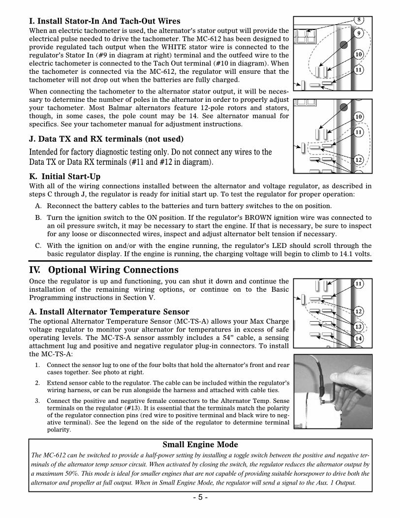
I. Install Stator-In And Tach-Out WiresWhen an electric tachometer is used, the alternator’s stator output will provide theelectrical pulse needed to drive the tachometer. The MC-612 has been designed toprovide regulated tach output when the WHITE stator wire is connected to theregulator’s Stator In (#9 in diagram at right) terminal and the outfeed wire to theelectric tachometer is connected to the Tach Out terminal (#10 in diagram). Whenthe tachometer is connected via the MC-612, the regulator will ensure that thetachometer will not drop out when the batteries are fully charged.
When connecting the tachometer to the alternator stator output, it will be neces-sary to determine the number of poles in the alternator in order to properly adjustyour tachometer. Most Balmar alternators feature 12-pole rotors and stators,though, in some cases, the pole count may be 14. See alternator manual forspecifics. See your tachometer manual for adjustment instructions.
K. Initial Start-UpWith all of the wiring connections installed between the alternator and voltage regulator, as described insteps C through J, the regulator is ready for initial start up. To test the regulator for proper operation:
A. Reconnect the battery cables to the batteries and turn battery switches to the on position.
B. Turn the ignition switch to the ON position. If the regulator’s BROWN ignition wire was connected toan oil pressure switch, it may be necessary to start the engine. If that is necessary, be sure to inspectfor any loose or disconnected wires, inspect and adjust alternator belt tension if necessary.
C. With the ignition on and/or with the engine running, the regulator’s LED should scroll through thebasic regulator display. If the engine is running, the charging voltage will begin to climb to 14.1 volts.
IV. Optional Wiring ConnectionsOnce the regulator is up and functioning, you can shut it down and continue theinstallation of the remaining wiring options, or continue on to the BasicProgramming instructions in Section V.
A. Install Alternator Temperature SensorThe optional Alternator Temperature Sensor (MC-TS-A) allows your Max Chargevoltage regulator to monitor your alternator for temperatures in excess of safeoperating levels. The MC-TS-A sensor assmbly includes a 54” cable, a sensingattachment lug and positive and negative regulator plug-in connectors. To installthe MC-TS-A:
1. Connect the sensor lug to one of the four bolts that hold the alternator’s front and rearcases together. See photo at right.
2. Extend sensor cable to the regulator. The cable can be included within the regulator’swiring harness, or can be run alongside the harness and attached with cable ties.
3. Connect the positive and negative female connectors to the Alternator Temp. Senseterminals on the regulator (#13). It is essential that the terminals match the polarityof the regulator connection pins (red wire to positive terminal and black wire to neg-ative terminal). See the legend on the side of the regulator to determine terminalpolarity.
Small Engine ModeThe MC-612 can be switched to provide a half-power setting by installing a toggle switch between the positive and negative ter-minals of the alternator temp sensor circuit. When activated by closing the switch, the regulator reduces the alternator output bya maximum 50%. This mode is ideal for smaller engines that are not capable of providing suitable horsepower to drive both thealternator and propeller at full output. When in Small Engine Mode, the regulator will send a signal to the Aux. 1 Output.
- 6 -
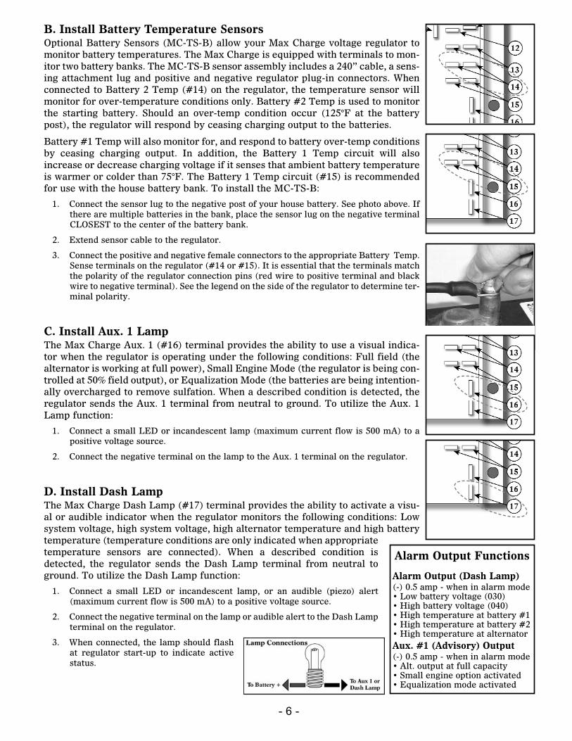
D. Install Dash LampThe Max Charge Dash Lamp (#17) terminal provides the ability to activate a visu-al or audible indicator when the regulator monitors the following conditions: Lowsystem voltage, high system voltage, high alternator temperature and high batterytemperature (temperature conditions are only indicated when appropriatetemperature sensors are connected). When a described condition isdetected, the regulator sends the Dash Lamp terminal from neutral toground. To utilize the Dash Lamp function:
1. Connect a small LED or incandescent lamp, or an audible (piezo) alert(maximum current flow is 500 mA) to a positive voltage source.
2. Connect the negative terminal on the lamp or audible alert to the Dash Lampterminal on the regulator.
3. When connected, the lamp should flashat regulator start-up to indicate activestatus.
B. Install Battery Temperature SensorsOptional Battery Sensors (MC-TS-B) allow your Max Charge voltage regulator tomonitor battery temperatures. The Max Charge is equipped with terminals to mon-itor two battery banks. The MC-TS-B sensor assembly includes a 240” cable, a sens-ing attachment lug and positive and negative regulator plug-in connectors. Whenconnected to Battery 2 Temp (#14) on the regulator, the temperature sensor willmonitor for over-temperature conditions only. Battery #2 Temp is used to monitorthe starting battery. Should an over-temp condition occur (125°F at the batterypost), the regulator will respond by ceasing charging output to the batteries.
Battery #1 Temp will also monitor for, and respond to battery over-temp conditionsby ceasing charging output. In addition, the Battery 1 Temp circuit will alsoincrease or decrease charging voltage if it senses that ambient battery temperatureis warmer or colder than 75°F. The Battery 1 Temp circuit (#15) is recommendedfor use with the house battery bank. To install the MC-TS-B:
1. Connect the sensor lug to the negative post of your house battery. See photo above. Ifthere are multiple batteries in the bank, place the sensor lug on the negative terminalCLOSEST to the center of the battery bank.
2. Extend sensor cable to the regulator.
3. Connect the positive and negative female connectors to the appropriate Battery Temp.Sense terminals on the regulator (#14 or #15). It is essential that the terminals matchthe polarity of the regulator connection pins (red wire to positive terminal and blackwire to negative terminal). See the legend on the side of the regulator to determine ter-minal polarity.
C. Install Aux. 1 LampThe Max Charge Aux. 1 (#16) terminal provides the ability to use a visual indica-tor when the regulator is operating under the following conditions: Full field (thealternator is working at full power), Small Engine Mode (the regulator is being con-trolled at 50% field output), or Equalization Mode (the batteries are being intention-ally overcharged to remove sulfation. When a described condition is detected, theregulator sends the Aux. 1 terminal from neutral to ground. To utilize the Aux. 1Lamp function:
1. Connect a small LED or incandescent lamp (maximum current flow is 500 mA) to apositive voltage source.
2. Connect the negative terminal on the lamp to the Aux. 1 terminal on the regulator.
Alarm Output Functions
Alarm Output (Dash Lamp)(-) 0.5 amp - when in alarm mode• Low battery voltage (030)• High battery voltage (040)• High temperature at battery #1 • High temperature at battery #2 • High temperature at alternator Aux. #1 (Advisory) Output(-) 0.5 amp - when in alarm mode• Alt. output at full capacity• Small engine option activated • Equalization mode activated
- 7 -
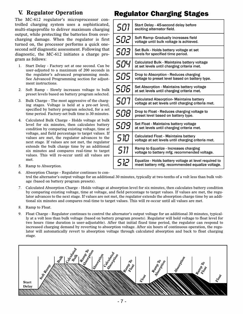
V. Regulator OperationThe MC-612 regulator’s microprocessor con-trolled charging system uses a sophisticated,multi-stageprofile to deliver maximum chargingoutput, while protecting the batteries from over-charging damage. When the regulator is firstturned on, the processor performs a quick one-second self diagnostic assessment. Following thatdiagnostic, the MC-612 initiates a charge pro-gram as follows:
1. Start Delay - Factory set at one second. Can beuser-adjusted to a maximum of 200 seconds inthe regulator’s advanced programming mode.See Advanced Programming section for adjust-ment instructions.
2. Soft Ramp - Slowly increases voltage to bulkpreset levels based on battery program selected.
3. Bulk Charge - The most aggressive of the charg-ing stages. Voltage is held at a pre-set level,specified by battery program selected, for a settime period. Factory-set bulk time is 30 minutes.
4. Calculated Bulk Charge - Holds voltage at bulklevel for six minutes, then calculates batterycondition by comparing existing voltage, time atvoltage, and field percentage to target values. Ifvalues are met, the regulator advances to thenext stage. If values are not met, the regulatorextends the bulk charge time by an additionalsix minutes and compares real-time to targetvalues. This will re-occur until all values aremet.
5. Ramp to Absorption.
6. Absorption Charge - Regulator continues to con-trol the alternator’s output voltage for an additional 30 minutes, typically at two-tenths of a volt less than bulk volt-age (based on battery program presets).
7. Calculated Absorption Charge - Holds voltage at absorption level for six minutes, then calculates battery conditionby comparing existing voltage, time at voltage, and field percentage to target values. If values are met, the regu-lator advances to the next stage. If values are not met, the regulator extends the absorption charge time by an addi-tional six minutes and compares real-time to target values. This will re-occur until all values are met.
8. Ramp to Float.
9. Float Charge - Regulator continues to control the alternator’s output voltage for an additional 30 minutes, typical-ly at a volt less than bulk voltage (based on battery program presets). Regulator will hold voltage to float level fortwo hours (time duration is user-adjustable). After that initial fixed time period, the regulator can respond toincreased charging demand by reverting to absorption voltage. After six hours of continuous operation, the regu-lator will automatically revert to absorption voltage through calculated absorption and back to float chargingstage.
- 8 -
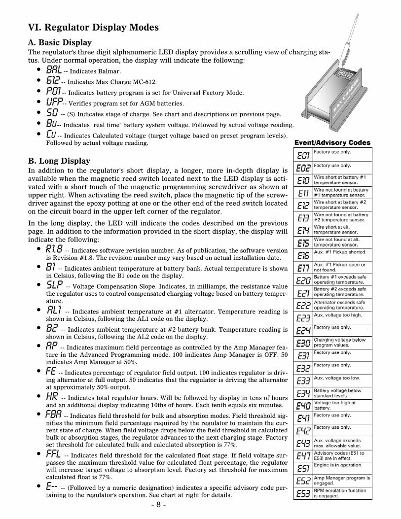
VI. Regulator Display Modes
A. Basic DisplayThe regulator's three digit alphanumeric LED display provides a scrolling view of charging sta-tus. Under normal operation, the display will indicate the following:
• bal -- Indicates Balmar.
• 612 -- Indicates Max Charge MC-612.
• P01 -- Indicates battery program is set for Universal Factory Mode.
• UFP-- Verifies program set for AGM batteries.
• S0 -- (S) Indicates stage of charge. See chart and descriptions on previous page.
• Bu -- Indicates "real time" battery system voltage. Followed by actual voltage reading.
• cu -- Indicates Calculated voltage (target voltage based on preset program levels).Followed by actual voltage reading.
B. Long DisplayIn addition to the regulator's short display, a longer, more in-depth display isavailable when the magnetic reed switch located next to the LED display is acti-vated with a short touch of the magnetic programming screwdriver as shown atupper right. When activating the reed switch, place the magnetic tip of the screw-driver against the epoxy potting at one or the other end of the reed switch locatedon the circuit board in the upper left corner of the regulator.
In the long display, the LED will indicate the codes described on the previouspage. In addition to the information provided in the short display, the display willindicate the following:
• R1.8 -- Indicates software revision number. As of publication, the software versionis Revision #1.8. The revision number may vary based on actual installation date.
• B1 -- Indicates ambient temperature at battery bank. Actual temperature is shownin Celsius, following the B1 code on the display.
• slp -- Voltage Compensation Slope. Indicates, in milliamps, the resistance valuethe regulator uses to control compensated charging voltage based on battery temper-ature.
• Al1 -- Indicates ambient temperature at #1 alternator. Temperature reading isshown in Celsius, following the AL1 code on the display.
• b2 -- Indicates ambient temperature at #2 battery bank. Temperature reading isshown in Celsius, following the AL2 code on the display.
• ap -- Indicates maximum field percentage as controlled by the Amp Manager fea-ture in the Advanced Programming mode. 100 indicates Amp Manager is OFF. 50indicates Amp Manager at 50%.
• fe -- Indicates percentage of regulator field output. 100 indicates regulator is driv-ing alternator at full output. 50 indicates that the regulator is driving the alternatorat approximately 50% output.
• Hr -- Indicates total regulator hours. Will be followed by display in tens of hoursand an additional display indicating 10ths of hours. Each tenth equals six minutes.
• Fba -- Indicates field threshold for bulk and absorption modes. Field threshold sig-nifies the minimum field percentage required by the regulator to maintain the cur-rent state of charge. When field voltage drops below the field threshold in calculatedbulk or absorption stages, the regulator advances to the next charging stage. Factoryset threshold for calculated bulk and calculated absorption is 77%.
• Ffl -- Indicates field threshold for the calculated float stage. If field voltage sur-passes the maximum threshold value for calculated float percentage, the regulatorwill increase target voltage to absorption level. Factory set threshold for maximumcalculated float is 77%.
• E-- -- (Followed by a numeric designation) indicates a specific advisory code per-taining to the regulator's operation. See chart at right for details.
- 9 -
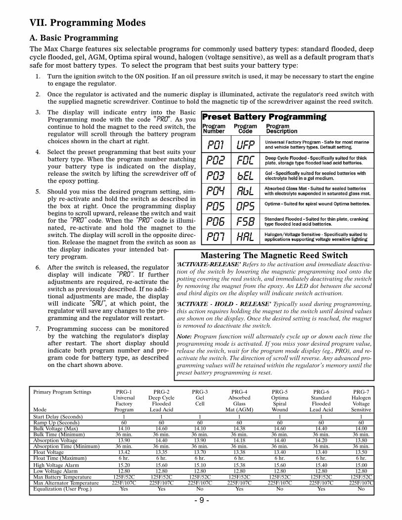
Primary Program Settings PRG-1 PRG-2 PRG-3 PRG-4 PRG-5 PRG-6 PRG-7Universal Deep Cycle Gel Absorbed Optima Standard HalogenFactory Flooded Cell Glass Spiral Flooded Voltage
Mode Program Lead Acid Mat (AGM) Wound Lead Acid SensitiveStart Delay (Seconds) 1 1 1 1 1 1 1 Ramp Up (Seconds) 60 60 60 60 60 60 60Bulk Voltage (Max) 14.10 14.60 14.10 14.38 14.60 14.40 14.00Bulk Time (Minimum) 36 min. 36 min. 36 min. 36 min. 36 min. 36 min. 36 min.Absorption Voltage 13.90 14.40 13.90 14.18 14.40 14.20 13.80Absorption Time (Minimum) 36 min. 36 min. 36 min. 36 min. 36 min. 36 min. 36 min.Float Voltage 13.42 13.35 13.70 13.38 13.40 13.40 13.50Float Time (Maximum) 6 hr. 6 hr. 6 hr. 6 hr. 6 hr. 6 hr. 6 hr.High Voltage Alarm 15.20 15.60 15.10 15.38 15.60 15.40 15.00Low Voltage Alarm 12.80 12.80 12.80 12.80 12.80 12.80 12.80Max Battery Temperature 125F/52C 125F/52C 125F/52C 125F/52C 125F/52C 125F/52C 125F/52CMax Alternator Temperature 225F/107C 225F/107C 225F/107C 225F/107C 225F/107C 225F/107C 225F/107CEqualization (User Prog.) Yes Yes No Yes No Yes No
VII. Programming Modes
A. Basic ProgrammingThe Max Charge features six selectable programs for commonly used battery types: standard flooded, deepcycle flooded, gel, AGM, Optima spiral wound, halogen (voltage sensitive), as well as a default program that'ssafe for most battery types. To select the program that best suits your battery type:
1. Turn the ignition switch to the ON position. If an oil pressure switch is used, it may be necessary to start the engineto engage the regulator.
2. Once the regulator is activated and the numeric display is illuminated, activate the regulator's reed switch withthe supplied magnetic screwdriver. Continue to hold the magnetic tip of the screwdriver against the reed switch.
3. The display will indicate entry into the BasicProgramming mode with the code "PRO". As youcontinue to hold the magnet to the reed switch, theregulator will scroll through the battery programchoices shown in the chart at right.
4. Select the preset programming that best suits yourbattery type. When the program number matchingyour battery type is indicated on the display,release the switch by lifting the screwdriver off ofthe epoxy potting.
5. Should you miss the desired program setting, sim-ply re-activate and hold the switch as described inthe box at right. Once the programming displaybegins to scroll upward, release the switch and waitfor the "PRO" code. When the "PRO" code is illumi-nated, re-activate and hold the magnet to theswitch. The display will scroll in the opposite direc-tion. Release the magnet from the switch as soon asthe display indicates your intended bat-tery program.
6. After the switch is released, the regulatordisplay will indicate "PRO". If furtheradjustments are required, re-activate theswitch as previously described. If no addi-tional adjustments are made, the displaywill indicate "SAu", at which point, theregulator will save any changes to the pro-gramming and the regulator will restart.
7. Programming success can be monitoredby the watching the regulator's displayafter restart. The short display shouldindicate both program number and pro-gram code for battery type, as describedon the chart shown above.
Mastering The Magnetic Reed Switch‘ACTIVATE-RELEASE’ Refers to the activation and immediate deactiva-tion of the switch by lowering the magnetic programming tool onto thepotting covering the reed switch, and immediately deactivating the switchby removing the magnet from the epoxy. An LED dot between the secondand third digits on the display will indicate switch activation.
‘ACTIVATE - HOLD - RELEASE’ Typically used during programming,this action requires holding the magnet to the switch until desired valuesare shown on the display. Once the desired setting is reached, the magnetis removed to deactivate the switch.
Note: Program function will alternately cycle up or down each time theprogramming mode is activated. If you miss your desired program value,release the switch, wait for the program mode display (eg., PRO), and re-activate the switch. The direction of scroll will reverse. Any advanced pro-gramming values will be retained within the regulator’s memory until thepreset battery programming is reset.
- 10 -
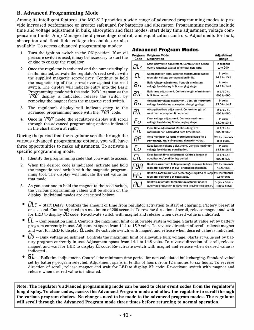
B. Advanced Programming ModeAmong its intelligent features, the MC-612 provides a wide range of advanced programming modes to pro-vide increased performance or greater safeguard for batteries and alternator. Programming modes includetime and voltage adjustment in bulk, absorption and float modes, start delay time adjustment, voltage com-pensation limits, Amp Manager field percentage control, and equalization controls. Adjustments for bulk,absorption and float field voltage thresholds are alsoavailable. To access advanced programming modes:
1. Turn the ignition switch to the ON position. If an oilpressure switch is used, it may be necessary to start theengine to engage the regulator.
2. Once the regulator is activated and the numeric displayis illuminated, activate the regulator's reed switch withthe supplied magnetic screwdriver. Continue to holdthe magnetic tip of the screwdriver against the reedswitch. The display will indicate entry into the BasicProgramming mode with the code "PRO". As soon as the"PRO" display is indicated, release the switch byremoving the magnet from the magnetic reed switch.
3. The regulator's display will indicate entry to theadvanced programming mode with the "PRA" code.
4. Once in "PRA" mode, the regulator's display will scrollthrough the advanced programming options indicatedin the chart shown at right.
During the period that the regulator scrolls through thevarious advanced programming options, you will havethree opportunities to make adjustments. To activate aspecific programming mode:
1. Identify the programming code that you want to access.
2. When the desired code is indicated, activate and holdthe magnetic reed switch with the magnetic program-ming tool. The display will indicate the set value forthat mode.
3. As you continue to hold the magnet to the reed switch,the various programming values will be shown on thedisplay. Individual modes are described below:
• dlc -- Start Delay. Controls the amount of time from regulator activation to start of charging. Factory preset atone second. Can be adjusted to a maximum of 200 seconds. To reverse direction of scroll, release magnet and waitfor LED to display dlc code. Re-activate switch with magnet and release when desired value is indicated.
• Cl -- Compensation Limit. Controls the maximum limit of allowable system voltage. Starts at value set by batteryprogram currently in use. Adjustment spans from 14.1 to 15.9 volts. To reverse direction of scroll, release magnetand wait for LED to display Cl code. Re-activate switch with magnet and release when desired value is indicated.
• Bu -- Bulk voltage adjustment. Controls the maximum limit of allowable bulk voltage. Starts at value set by bat-tery program currently in use. Adjustment spans from 14.1 to 14.8 volts. To reverse direction of scroll, releasemagnet and wait for LED to display bu code. Re-activate switch with magnet and release when desired value isindicated.
• B1c -- Bulk time adjustment. Controls the minimum time period for non-calculated bulk charging. Standard valueset by battery program selected. Adjustment spans in tenths of hours from 12 minutes to six hours. To reversedirection of scroll, release magnet and wait for LED to display b1c code. Re-activate switch with magnet andrelease when desired value is indicated.
Note: The regulator’s advanced programming mode can be used to clear event codes from the regulator’slong display. To clear codes, access the Advanced Program mode and allow the regulator to scroll throughthe various program choices. No changes need to be made to the advanced program modes. The regulatorwill scroll through the Advanced Program mode three times before returning to normal operation.
- 11 -
• Au -- Absorption voltage adjustment. Controls the maximum limit of allowable absorption voltage. Starts at valueset by battery program currently in use. Adjustment spans from 13.5 to 14.8 volts. To reverse direction of scroll,release magnet and wait for LED to display au code. Re-activate switch with magnet and release when desiredvalue is indicated.
• A1c -- Absorption time adjustment. Controls the minimum time period for non-calculated absorption charging.Standard value set by battery program selected. Adjustment spans in tenths of hours from 12 minutes to six hours.To reverse direction of scroll, release magnet and wait for LED to display a1c code. Re-activate switch with mag-net and release when desired value is indicated.
• Fu -- Float voltage adjustment. Controls the maximum limit of allowable float voltage. Starts at value set by bat-tery program currently in use. Adjustment spans from 13.0 to 13.8 volts. To reverse direction of scroll, releasemagnet and wait for LED to display au code. Re-activate switch with magnet and release when desired value isindicated.
• F1c -- Float time adjustment. Controls the minimum time period for non-calculated float charging. Standard valueis set by the battery program selected. Adjustment spans in tenths of hours from 12 minutes to six hours. Toreverse direction of scroll, release magnet and wait for LED to displaya1c code. Re-activate switch with magnet and release when desired valueis indicated.
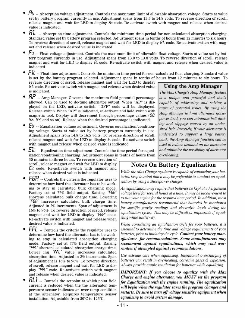
• ap -- Amp Manager. Governs the maximum field potential percentageallowed. Can be used to de-tune alternator output. When “AP” is dis-played on the LED, activate switch. “OFF” code will be displayed.Release switch. When “AP” is indicated, re-activate and hold switch withmagnetic tool. Display will decrement through percentage values (98,96, 94, and so on). Release when the desired percentage is indicated.
• eu -- Equalization voltage adjustment. Governs equalization/condition-ing voltage. Starts at value set by battery program currently in use.Adjustment spans from 14.8 to 16.5 volts. To reverse direction of scroll,release magnet and wait for LED to display eu code. Re-activate switchwith magnet and release when desired value is indicated.
• e1c -- Equalization time adjustment. Controls the time period for equal-ization/conditioning charging. Adjustment spans in tenths of hours from30 minutes to three hours. To reverse direction ofscroll, release magnet and wait for LED to displaye1c code. Re-activate switch with magnet andrelease when desired value is indicated.
• fba -- Controls the criteria the regulator uses todetermine how hard the alternator has to be work-ing to stay in calculated bulk charging mode.Factory set at 77% field output. Raising “fba”shortens calculated bulk charge time. Lowering“fba” increases calculated bulk charge time.Adjusted in 2% increments. Span of adjustment is16% to 96%. To reverse direction of scroll, releasemagnet and wait for LED to display “fba” code.Re-activate switch with magnet and release whendesired value is indicated.
• ffl -- Controls the criteria the regulator uses todetermine how hard the alternator has to be work-ing to stay in calculated absorption chargingmode. Factory set at 77% field output. Raising“ffl” shortens calculated absorption charge time.Lower ing “ffl” value increases calculatedabsorption time. Adjusted in 2% increments. Spanof adjustment is 16% to 96%. To reverse directionof scroll, release magnet and wait for LED to dis-play “ffl” code. Re-activate switch with magnetand release when desired value is indicated.
• al1 -- Controls the setpoint at which point fieldcurrent is reduced when the the alternator tem-perature sensor indicates an over-temp conditionat the alternator. Requires temperature sensorinstallation. Adjustable from 30°C to 125°C.
Using the Amp ManagerThe Max Charge’s Amp Manager featureis a unique and powerful tool that’scapable of addressing and solving arange of potential issues. By using theAmp Manager to limit alternator horse-power load, you can minimize belt dust-ing and slippage caused by an under-sized belt. Inversely, if your alternator isundersized to support a large batterybank, the Amp Manager function can beused to reduce demand on the alternatorand minimize the possibility of alternatoroverheating.
Notes On Battery EqualizationWhile the Max Charge regulator is capable of equalizing your bat-teries, keep in mind that it may be preferable to conduct an equal-ization by using a shorepower charger.
An equalization may require that batteries be kept at a heightenedvoltage level for several hours at a time. It may be inconvenient toto run your engine for the required time period. In addition, mostbattery manufacturers recommend that batteries be monitoredfor specific gravity readings and electrolyte levels during theequalization cycle). This may be difficult or impossible if equal-izing while underway.
When considering an equalization cycle for your batteries, it isessential to determine the time and voltage requirements of yourbatteries, prior to initiating the cycle. Contact your battery man-ufacturer for recommendations. Some manufacturers mayrecommend against equalizations, which may void war-ranties if attempted against recommendations.
Use extreme care when equalizing. Intentional overcharging ofbatteries can result in overheating, corrosive gases & explosion.Always provide ample ventilation for batteries while equalizing.
IMPORTANT: If you choose to equalize with the MaxCharge and engine alternator, you MUST set the programfor Equalization with the engine running. The equalizationwill begin when the regulator saves the program changes andrestarts. Be sure to turn off voltage sensitive equipment whenequalizing to avoid system damage.
- 12 -
VIII. System TroubleshootingThe majority of charging difficulties can be attributed to damage, corrosion or wear at wires or wiring con-nections. Before attempting to troubleshoot alternator or regulator issues, be sure to address the following:
1. Remove and clean all charging system electrical connections (positive and negative). Check the voltage regulator’sharness for resistance. Wires and terminals can and will become corroded, and need to be cleaned or replaced.
2. Charge all batteries to their proper fully charged state, and determine if they are serviceable. If your batteries areflooded-type, use your hydrometer to determine their condition.
3. Check and tighten alternator belt. If the belt show signs of wear or damage, replace it. Always replace existingbelts with the finest quality replacements available.
If batteries and wiring are in suitable condition, use the following tests to determine if charging problemsare a result of a faulty alternator or regulator. These tests provide an opportunity to isolate the alternator,regulator and wiring harness in order to determine which component may be malfunctioning. In order toperform these tests, you will need an independent DC meter (preferably a digital type). In an emergency, a12V light bulb or test light can be used to help determine if power or working grounds exist. An amp meterand a battery hydrometer with a thermometer are also helpful diagnostic tools.
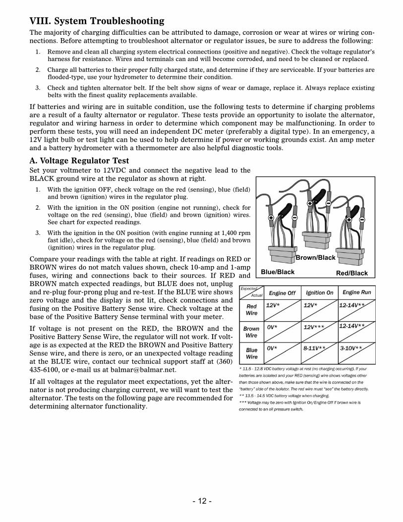
A. Voltage Regulator TestSet your voltmeter to 12VDC and connect the negative lead to theBLACK ground wire at the regulator as shown at right.
1. With the ignition OFF, check voltage on the red (sensing), blue (field)and brown (ignition) wires in the regulator plug.
2. With the ignition in the ON position (engine not running), check forvoltage on the red (sensing), blue (field) and brown (ignition) wires.See chart for expected readings.
3. With the ignition in the ON position (with engine running at 1,400 rpmfast idle), check for voltage on the red (sensing), blue (field) and brown(ignition) wires in the regulator plug.
Compare your readings with the table at right. If readings on RED orBROWN wires do not match values shown, check 10-amp and 1-ampfuses, wiring and connections back to their sources. If RED andBROWN match expected readings, but BLUE does not, unplugand re-plug four-prong plug and re-test. If the BLUE wire showszero voltage and the display is not lit, check connections andfusing on the Positive Battery Sense wire. Check voltage at thebase of the Positive Battery Sense terminal with your meter.
If voltage is not present on the RED, the BROWN and thePositive Battery Sense Wire, the regulator will not work. If volt-age is as expected at the RED the BROWN and Positive BatterySense wire, and there is zero, or an unexpected voltage readingat the BLUE wire, contact our technical support staff at (360)435-6100, or e-mail us at [email protected].
If all voltages at the regulator meet expectations, yet the alter-nator is not producing charging current, we will want to test thealternator. The tests on the following page are recommended fordetermining alternator functionality.
Red/Black
Brown/Black
Blue/Black
- 13 -
B. Alternator testingTest A - The alternator and regulator can be tested for function by determining if a magnetic field exists atthe alternator’s pulley shaft or rear bearing. To test:
1. With the ignition in the OFF position, place the tip of a steel screwdriver near the nut on the pulley shaft or nearthe rear bearing of the alternator. There should be no evidence of a magnetic field pulling the screwdriver towardthe alternator. (A slight amount of magnetism may be present, due to residual voltage in the alternator.
2. Engage the ignition, without starting the engine, to activate the voltage regulator. If an oil pressure switch is used,a jumper between the RED and BROWN wires in the Ford-style plug will activate the regulator.
3. After allowing time for the regulator’s start-up delay, place the head of a steel screwdriver near the nut on the pul-ley shaft or near the rear bearing of the alternator. There should be substantial magnetic pull. If a magnetic fieldis present, the voltage regulator, alternator brushes and rotor are likely to be working properly.
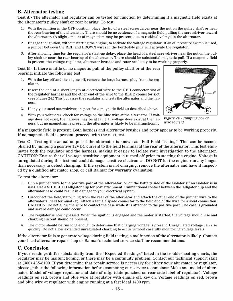
Test B - If there is little or no magnetic pull at the pulley shaft or at the rearbearing, initiate the following test:
1. With the key off and the engine off, remove the large harness plug from the reg-ulator.
2. Insert the end of a short length of electrical wire to the RED connector slot ofthe regulator harness and the other end of the wire to the BLUE connector slot.(See Figure 24.) This bypasses the regulator and tests the alternator and the har-ness.
3. Using your steel screwdriver, inspect for a magnetic field as described above.
4. With your voltmeter, check for voltage on the blue wire at the alternator. If volt-age does not exist, the harness may be at fault. If voltage does exist at the har-ness, but no magnetism is present, the alternator is likely to be malfunctioning.
If a magnetic field is present. Both harness and alternator brushes and rotor appear to be working properly.If no magnetic field is present, proceed with the next test.
Test C - Testing the actual output of the alternator is known as “Full Field Testing”. This can be accom-plished by jumping a positive 12VDC current to the field terminal at the rear of the alternator. This test elim-inates both the regulator and the harness, making it easier to isolate your investigation to the alternator.CAUTION: Ensure that all voltage sensitive equipment is turned off prior to starting the engine. Voltage isunregulated during this test and could damage sensitive electronics. DO NOT let the engine run any longerthan necessary to detect charging. If the system is not charging, remove the alternator and have it inspect-ed by a qualified alternator shop, or call Balmar for warranty evaluation.
To test the alternator:
1. Clip a jumper wire to the positive post of the alternator, or on the battery side of the isolator (if an isolator is inuse). Use a SHIELDED alligator clip for post attachment. Unintentional contact between the alligator clip and thealternator case could result in damage to your electrical system.
2. Disconnect the field/stator plug from the rear of the alternator and attach the other end of the jumper wire to thealternator’s Field terminal (F). Attach a female spade connector to the field end of the wire for a solid connection.CAUTION: Do not allow the wire to contact the case while it is attached to the positive post. The case is groundedand severe damage could occur.
3. The regulator is now bypassed. When the ignition is engaged and the motor is started, the voltage should rise andcharging current should be present.
4. The motor should be run long enough to determine that charging voltage is present. Unregulated voltage can risequickly. Do not allow extended unregulated charging to occur without carefully monitoring voltage levels.
If the alternator fails to generate voltage during field testing, a malfunction of the alternator is likely. Contactyour local alternator repair shop or Balmar’s technical service staff for recommendations.
C. ConclusionIf your readings differ substantially from the “Expected Readings” listed in the troubleshooting charts, theregulator may be malfunctioning, or there may be a continuity problem. Contact our technical support staffat (360) 435-6100. If you determine that repair service is necessary for either your alternator or regulator,please gather the following information before contacting our service technicians: Make and model of alter-nator. Model of voltage regulator and date of mfg. (date punched on rear side label of regulator). Voltagereadings on red, brown and blue wire at regulator with engine off, key on. Voltage readings on red, brownand blue wire at regulator with engine running at a fast ideal 1400 rpm.
RBl Figure 24 - Jumping powerwire to field.
- 14 -
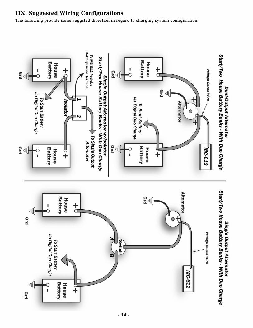
IIX. Suggested Wiring ConfigurationsThe following provide some suggsted direction in regard to charging system configuration.
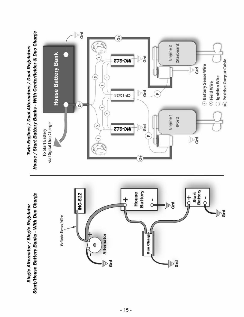
- 15 -
- 16 -
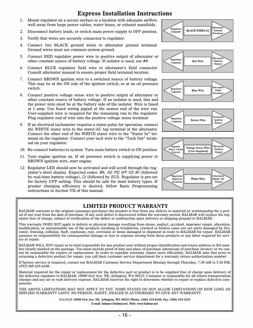
Express Installation Instructions1. Mount regulator on a secure surface in a location with adequate airflow,
well away from large power cables, water hoses, or exhaust manifolds.
2. Disconnect battery leads, or switch main power supply to OFF position.
3. Verify that wires are securely connected to regulator.
4. Connect two BLACK ground wires to alternator ground terminal.Ground wires must see common system ground.
5. Connect RED regulator power wire to positive output of alternator orother constant source of battery voltage. If isolator is used, see #8.
6. Connect BLUE regulator field wire to alternator’s field connector.Consult alternator manual to ensure proper field terminal location.
7. Connect BROWN ignition wire to a switched source of battery voltage.This may be at the ON side of the ignition switch, or at an oil pressureswitch.
8. Connect positive voltage sense wire to positive output of alternator orother constant source of battery voltage. If an isolator is used, this andthe power wire must be at the battery side of the isolator. Wire is fusedat 1 amp. Use fused wiring pigtail at the source end of the wire run.User-supplied wire is required for the remaining run to the regulator.Plug regulator end of wire into the positive voltage sense terminal.
9. If an electrical tachometer requires a stator pulse for operation, connectthe WHITE stator wire to the stator/AC tap terminal at the alternator.Connect the other end of the WHITE stator wire to the “Stator In” ter-minal on the regulator. Connect your tach wire to the “Tach Out” termi-nal on your regulator.
10. Re-connect batteries to system. Turn main battery switch to ON position.
11. Turn engine ignition on. If oil pressure switch is supplying power toBROWN ignition wire, start engine.
12. Regulator LED should now be activated and will scroll through the reg-ulator’s short display. Expected codes: BAL, 612, P01, UFP, S01, Bv (followedby real-time battery voltage), cu (followed by 00.0). Regulator is pre-setfor factory UFP setting. This should be safe for most battery types. Ifgreater charging efficiency is desired, follow Basic Programminginstructions in Section VII of this manual.
LIMITED PRODUCT WARRANTYBALMAR warrants to the original consumer/purchaser the product is free from any defects in material or workmanship for a peri-od of one year from the date of purchase. If any such defect is discovered within the warranty period, BALMAR will replace the reg-ulator free of charge, subject to verification of the defect or malfunction upon delivery or shipping prepaid to BALMAR.
This warranty DOES NOT apply to defects or physical damage resulting from abuse, neglect, accident, improper repair, alteration,modification, or unreasonable use of the products resulting in breakdown, cracked or broken cases nor are parts damaged by fire,water, freezing, collision, theft, explosion, rust, corrosion or items damaged in shipment in route to BALMAR for repair. BALMARassumes no responsibility for consequential damage or loss or expense arising from these products or any labor required for serv-ice or repair.
BALMAR WILL NOT repair or be held responsible for any product sent without proper identification and return address or RA num-ber clearly marked on the package. You must include proof of date and place of purchase (photocopy of purchase invoice) or we can-not be responsible for repairs or replacement. In order to expedite warranty claims more efficiently, BALMAR asks that prior toreturning a defective product for repair, you call their customer service department for a warranty return authorization number .
If factory service is required, contact our BALMAR Customer Service Department Monday through Thursday, 7:30 AM to 5:30 PM,(PST)360 435-6100.
Material required for the repair or replacement for the defective part or product is to be supplied free of charge upon delivery ofthe defective regulator to BALMAR, 19009 61st Ave. NE, Arlington, WA 98223. Customer is responsible for all return transportationcharges and any air or rush delivery expense. BALMAR reserves the right to determine whether to repair or replace defective com-ponents.
THE ABOVE LIMITATIONS MAY NOT APPLY TO YOU. SOME STATES DO NOT ALLOW LIMITATIONS ON HOW LONG ANIMPLIED WARRANTY LASTS. NO PERSON, AGENT, DEALER IS AUTHORIZED TO GIVE ANY WARRANTY.
BALMAR 19009 61st Ave. NE, Arlington, WA 98223 Phone: (360) 435-6100, Fax: (360) 435-3210E-mail: [email protected], Web: www.balmar.net
Ignition
Connector
Connector
Connector
Connector