Embed Size (px)
Citation preview

Maximum Flow
Chapter 26

Flow Graph
• A common scenario is to use a graph to represent a “flow network” and use it to answer questions about material flows
• Flow is the rate that material moves through the network
• Each directed edge is a conduit for the material with some stated capacity
• Vertices are connection points but do not collect material– Flow into a vertex must equal the flow leaving the
vertex, flow conservation

Sample Networks
communication
Network
telephone exchanges,computers, satellites
Nodes Arcs
cables, fiber optics,microwave relays
Flow
voice, video,packets
circuitsgates, registers,processors
wires current
mechanical joints rods, beams, springs heat, energy
hydraulicreservoirs, pumpingstations, lakes
pipelines fluid, oil
financial stocks, companies transactions money
transportationairports, rail yards,street intersections
highways, railbeds,airway routes
freight,vehicles,passengers
chemical sites bonds energy

Flow Concepts
• Source vertex s – where material is produced
• Sink vertex t – where material is consumed
• For all other vertices – what goes in must go out– Flow conservation
• Goal: determine maximum rate of material flow from source to sink
Formal Max Flow Problem
– Graph G=(V,E) – a flow network• Directed, each edge has capacity c(u,v) 0• Two special vertices: source s, and sink t• For any other vertex v, there is a path s…v…t
– Flow – a function f : V V R• Capacity constraint: For all u, v V: f(u,v) c(u,v)• Skew symmetry: For all u, v V: f(u,v) = –f(v,u)• Flow conservation: For all u V – {s, t}:
, or( , ) ( , ) 0
( , ) ( , ) 0v V
v V
f u v f u V
f v u f V u
2/5
2/15
5/14
4/19
3/3
s t0/9
a
b

Cancellation of flows
• We would like to avoid two positive flows in opposite directions between the same pair of vertices– Such flows cancel (maybe partially) each other due to
skew symmetry
5/5
2/15
5/14
5/19
2/3
s t2/9
a
b
3/5
2/15
5/14
5/19
2/3
s t0/9
a
b

Max Flow
• We want to find a flow of maximum value from the source to the sink– Denoted by |f|
Lucky Puck Distribution Network Max Flow, |f| = 19Or is it?Best we can do?

Ford-Fulkerson method• Contains several algorithms:
– Residue networks– Augmenting paths
• Find a path p from s to t (augmenting path), such that there is some value x > 0, and for each edge (u,v) in p we can add x units of flow
– f(u,v) + x c(u,v)
8/13
8/11
5/52/4
10/15
10
6/14
13/19
3/3
s t9
a b
c d
Augmenting Path?

Residual Network
• To find augmenting path we can find any path in the residual network:– Residual capacities: cf(u,v) = c(u,v) – f(u,v)
• i.e. the actual capacity minus the net flow from u to v
• Net flow may be negative
– Residual network: Gf =(V,Ef), where
Ef = {(u,v) V V : cf(u,v) > 0}
– Observation – edges in Ef are either edges in E or their reversals: |Ef| 2|E|
0/14
5/15
a b
19
10
a b
Sub-graphWithc(u,v) andf(u,v)
ResidualSub-Graph
c
5/6
c
1
5

Residual Graph• Compute the residual graph of the graph with the
following flow:8/13
8/11
5/52/4
10/15
10
6/14
13/19
3/3
s t9
a b
c d

Residual Capacity and Augmenting Path
• Finding an Augmenting Path– Find a path from s to t in the residual graph– The residual capacity of a path p in Gf:
cf(p) = min{cf(u,v): (u,v) is in p}• i.e. find the minimum capacity along p
– Doing augmentation: for all (u,v) in p, we just add this cf(p) to f(u,v) (and subtract it from f(v,u))
– Resulting flow is a valid flow with a larger value.

Residual network and augmenting path
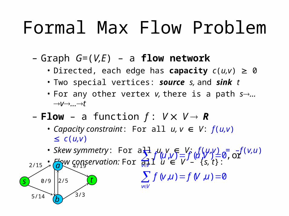
The Ford-Fulkerson method
Ford-Fulkerson(G,s,t) 1 for each edge (u,v) in G.E do 2 f(u,v) f(v,u) 0 3 while there exists a path p from s to t in residual
network Gf do4 cf = min{cf(u,v): (u,v) is in p} 5 for each edge (u,v) in p do6 f(u,v) f(u,v) + cf
7 f(v,u) -f(u,v)8 return f
The algorithms based on this method differ in how they choose p in step 3.If chosen poorly the algorithm might not terminate.

Execution of Ford-Fulkerson (1)
Left Side = Residual Graph Right Side = Augmented Flow
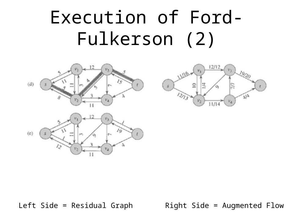
Execution of Ford-Fulkerson (2)
Left Side = Residual Graph Right Side = Augmented Flow

Cuts• Does the method find the minimum flow?
– Yes, if we get to the point where the residual graph has no path from s to t
– A cut is a partition of V into S and T = V – S, such that s S and t T– The net flow (f(S,T)) through the cut is the sum of flows f(u,v), where s
S and t T• Includes negative flows back from T to S
– The capacity (c(S,T)) of the cut is the sum of capacities c(u,v), where s S and t T
• The sum of positive capacities– Minimum cut – a cut with the smallest capacity of all cuts.
|f|= f(S,T) i.e. the value of a max flow is equal to the capacity of a min cut.
8/13
8/11
5/52/4
10/15
10
6/14
13/19
3/3
s t9
a b
c dCut capacity = 24 Min Cut capacity = 21

Max Flow / Min Cut Theorem
1. Since |f| c(S,T) for all cuts of (S,T) then if |f| = c(S,T) then c(S,T) must be the min cut of G
2. This implies that f is a maximum flow of G3. This implies that the residual network Gf
contains no augmenting paths.• If there were augmenting paths this would contradict
that we found the maximum flow of G
• 1231 … and from 23 we have that the Ford Fulkerson method finds the maximum flow if the residual graph has no augmenting paths.

Worst Case Running Time
• Assuming integer flow• Each augmentation increases the value of the flow by
some positive amount.• Augmentation can be done in O(E).• Total worst-case running time O(E|f*|), where f* is the
max-flow found by the algorithm.• Example of worst case:
Augmenting path of 1 Resulting Residual Network Resulting Residual Network

Edmonds Karp
• Take shortest path (in terms of number of edges) as an augmenting path – Edmonds-Karp algorithm– How do we find such a shortest path?– Running time O(VE2), because the number of
augmentations is O(VE)– Skipping the proof here
– Even better method: push-relabel, O(V2E) runtime

Multiple Sources or Sinks
• What if you have a problem with more than one source and more than one sink?
• Modify the graph to create a single supersource and supersink
13
11
54
15
10
14
13
3
s t9
a b
c d13
11
54
15
10
14
13
3
x y9
e f
g h
4
13
11
54
15
10
14
13
3
9
a b
c d13
11
54
15
10
14
13
3
9
e f
g h
4s
i
j
k
l
t

Application – Bipartite Matching
• Example – given a community with n men and m women
• Assume we have a way to determine which couples (man/woman) are compatible for marriage– E.g. (Joe, Susan) or (Fred, Susan) but not (Frank,
Susan)
• Problem: Maximize the number of marriages– No polygamy allowed– Can solve this problem by creating a flow network out
of a bipartite graph

Bipartite Graph
• A bipartite graph is an undirected graph G=(V,E) in which V can be partitioned into two sets V1 and V2 such that (u,v) E implies either u V1 and v V12 or vice versa.
• That is, all edges go between the two sets V1 and V2 and not within V1 and V2.
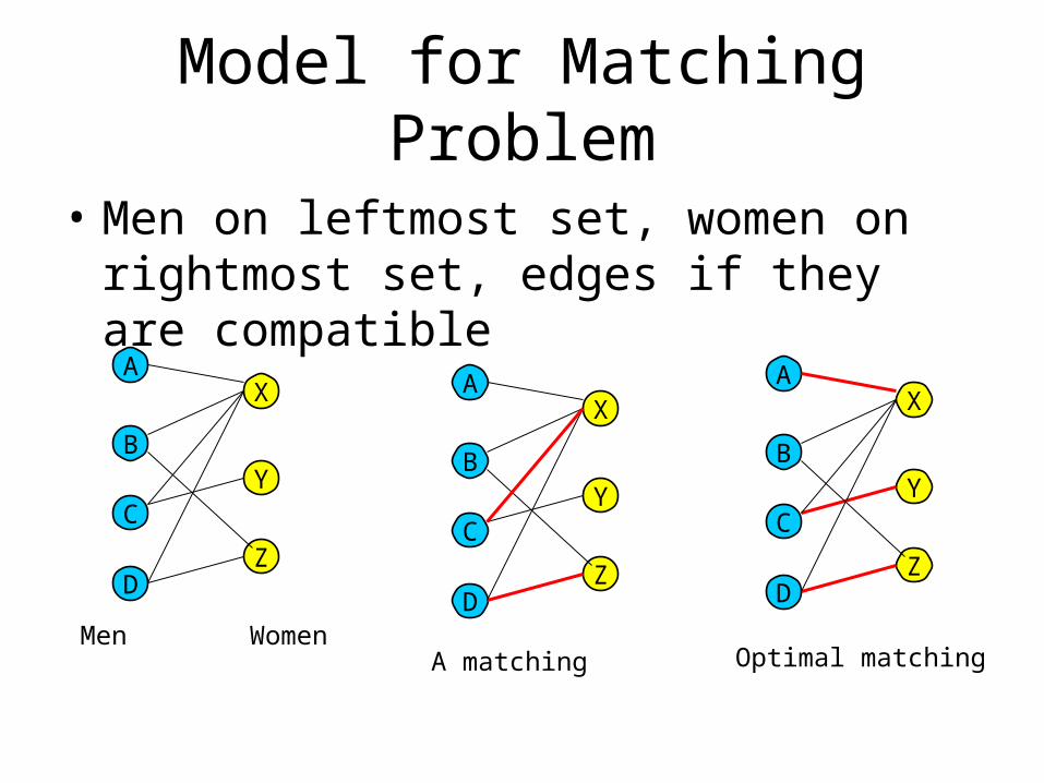
Model for Matching Problem
• Men on leftmost set, women on rightmost set, edges if they are compatible
A
B
C
D
X
Y
Z
Men Women
A
B
C
D
X
Y
Z
A matching
A
B
C
D
X
Y
Z
Optimal matching

Solution Using Max Flow
• Add a supersouce, supersink, make each undirected edge directed with a flow of 1
A
B
C
D
X
Y
Z
A
B
C
D
X
Y
Z
st
Since the input is 1, flow conservation prevents multiple matchings