Embed Size (px)
Citation preview
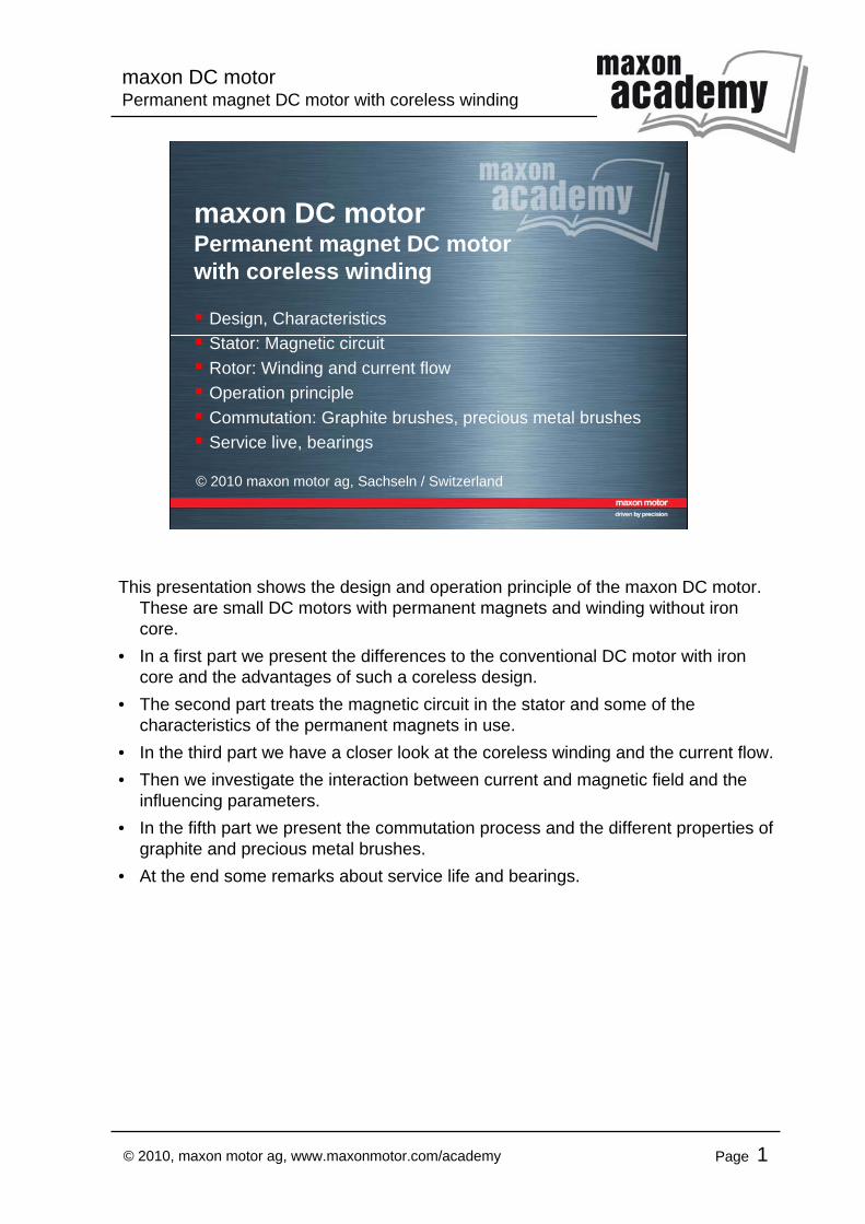
maxon DC motorPermanent magnet DC motor with coreless winding
Page 1© 2010, maxon motor ag, www.maxonmotor.com/academy
maxon DC motorPermanent magnet DC motor with coreless winding
Design, CharacteristicsStator: Magnetic circuitRotor: Winding and current flowOperation principleCommutation: Graphite brushes, precious metal brushesService live, bearings
© 2010 maxon motor ag, Sachseln / Switzerland
This presentation shows the design and operation principle of the maxon DC motor. These are small DC motors with permanent magnets and winding without iron core.
• In a first part we present the differences to the conventional DC motor with iron core and the advantages of such a coreless design.
• The second part treats the magnetic circuit in the stator and some of the characteristics of the permanent magnets in use.
• In the third part we have a closer look at the coreless winding and the current flow.• Then we investigate the interaction between current and magnetic field and the
influencing parameters.• In the fifth part we present the commutation process and the different properties of
graphite and precious metal brushes.• At the end some remarks about service life and bearings.
maxon DC motorPermanent magnet DC motor with coreless winding
Page 2© 2010, maxon motor ag, www.maxonmotor.com/academy
2, ©
2010
, max
on m
otor
ag,
ww
w.m
axon
mot
or.c
om/a
cade
my
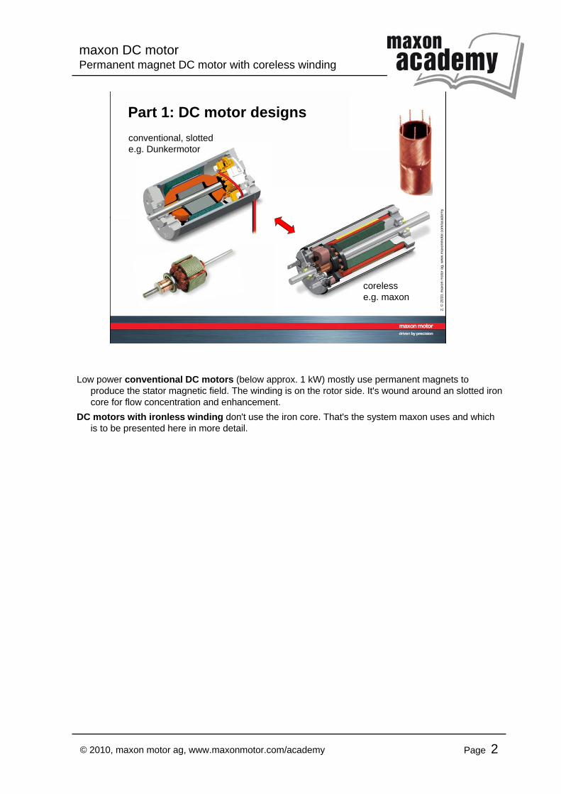
Part 1: DC motor designsconventional, slottede.g. Dunkermotor
corelesse.g. maxon
Low power conventional DC motors (below approx. 1 kW) mostly use permanent magnets to produce the stator magnetic field. The winding is on the rotor side. It's wound around an slotted iron core for flow concentration and enhancement.
DC motors with ironless winding don't use the iron core. That's the system maxon uses and whichis to be presented here in more detail.
maxon DC motorPermanent magnet DC motor with coreless winding
Page 3© 2010, maxon motor ag, www.maxonmotor.com/academy
3, ©
2010
, max
on m
otor
ag,
ww
w.m
axon
mot
or.c
om/a
cade
my
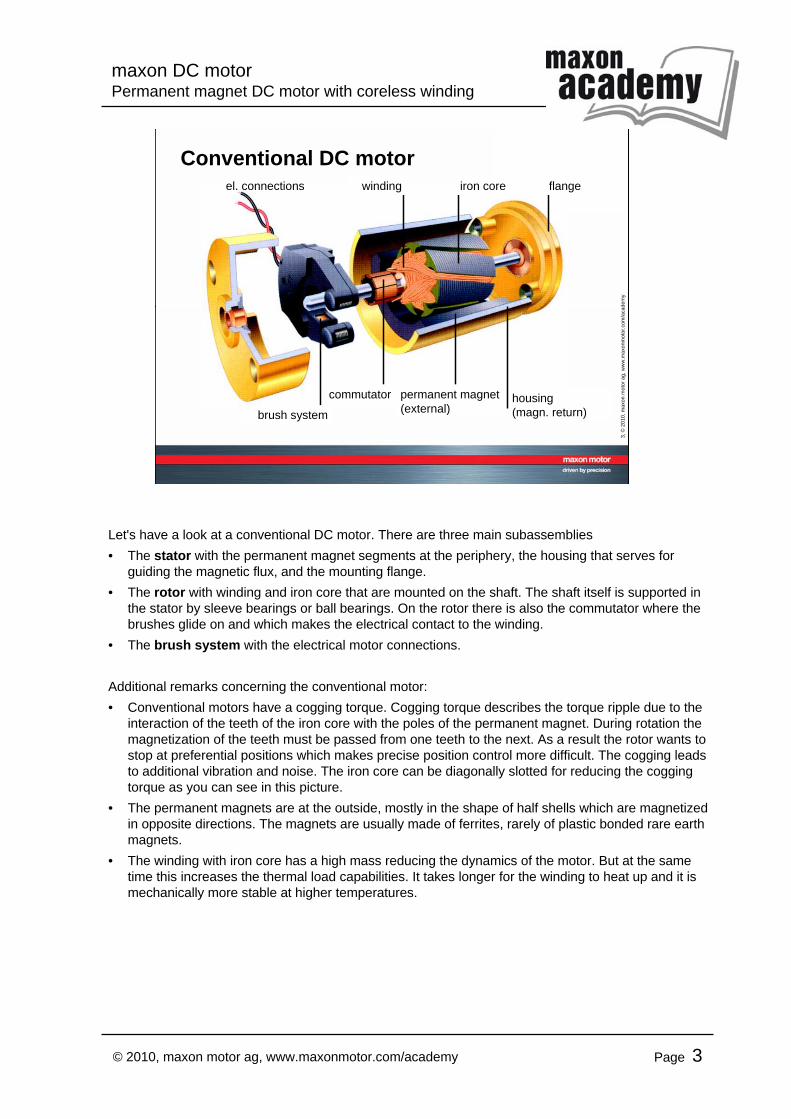
Conventional DC motorel. connections
housing(magn. return)
winding
commutator
brush system
iron core
permanent magnet(external)
flange
Let's have a look at a conventional DC motor. There are three main subassemblies• The stator with the permanent magnet segments at the periphery, the housing that serves for
guiding the magnetic flux, and the mounting flange.• The rotor with winding and iron core that are mounted on the shaft. The shaft itself is supported in
the stator by sleeve bearings or ball bearings. On the rotor there is also the commutator where the brushes glide on and which makes the electrical contact to the winding.
• The brush system with the electrical motor connections.
Additional remarks concerning the conventional motor:• Conventional motors have a cogging torque. Cogging torque describes the torque ripple due to the
interaction of the teeth of the iron core with the poles of the permanent magnet. During rotation the magnetization of the teeth must be passed from one teeth to the next. As a result the rotor wants to stop at preferential positions which makes precise position control more difficult. The cogging leads to additional vibration and noise. The iron core can be diagonally slotted for reducing the cogging torque as you can see in this picture.
• The permanent magnets are at the outside, mostly in the shape of half shells which are magnetized in opposite directions. The magnets are usually made of ferrites, rarely of plastic bonded rare earth magnets.
• The winding with iron core has a high mass reducing the dynamics of the motor. But at the same time this increases the thermal load capabilities. It takes longer for the winding to heat up and it is mechanically more stable at higher temperatures.
maxon DC motorPermanent magnet DC motor with coreless winding
Page 4© 2010, maxon motor ag, www.maxonmotor.com/academy
4, ©
2010
, max
on m
otor
ag,
ww
w.m
axon
mot
or.c
om/a
cade
my
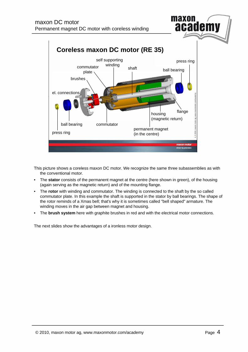
Coreless maxon DC motor (RE 35)
el. connections
self supportingwinding
commutator
brushes
permanent magnet(in the centre)
housing(magnetic return)
flange
commutatorplate
shaft
ball bearing
ball bearing
press ring
press ring
This picture shows a coreless maxon DC motor. We recognize the same three subassemblies as with the conventional motor.
• The stator consists of the permanent magnet at the centre (here shown in green), of the housing (again serving as the magnetic return) and of the mounting flange.
• The rotor with winding and commutator. The winding is connected to the shaft by the so called commutator plate. In this example the shaft is supported in the stator by ball bearings. The shape of the rotor reminds of a Xmas bell; that's why it is sometimes called "bell shaped" armature. The winding moves in the air gap between magnet and housing.
• The brush system here with graphite brushes in red and with the electrical motor connections.
The next slides show the advantages of a ironless motor design.
maxon DC motorPermanent magnet DC motor with coreless winding
Page 5© 2010, maxon motor ag, www.maxonmotor.com/academy
5, ©
2010
, max
on m
otor
ag,
ww
w.m
axon
mot
or.c
om/a
cade
my
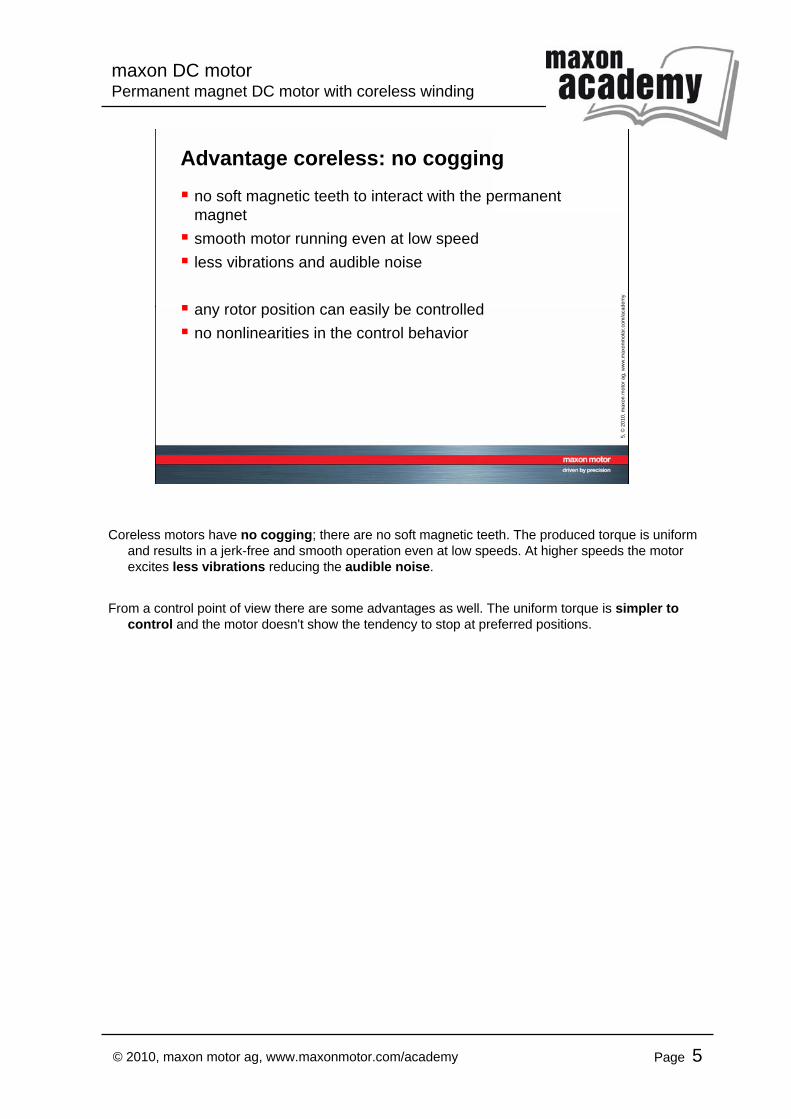
Advantage coreless: no coggingno soft magnetic teeth to interact with the permanent magnetsmooth motor running even at low speedless vibrations and audible noise
any rotor position can easily be controlledno nonlinearities in the control behavior
Coreless motors have no cogging; there are no soft magnetic teeth. The produced torque is uniform and results in a jerk-free and smooth operation even at low speeds. At higher speeds the motor excites less vibrations reducing the audible noise.
From a control point of view there are some advantages as well. The uniform torque is simpler to control and the motor doesn't show the tendency to stop at preferred positions.
maxon DC motorPermanent magnet DC motor with coreless winding
Page 6© 2010, maxon motor ag, www.maxonmotor.com/academy
6, ©
2010
, max
on m
otor
ag,
ww
w.m
axon
mot
or.c
om/a
cade
my
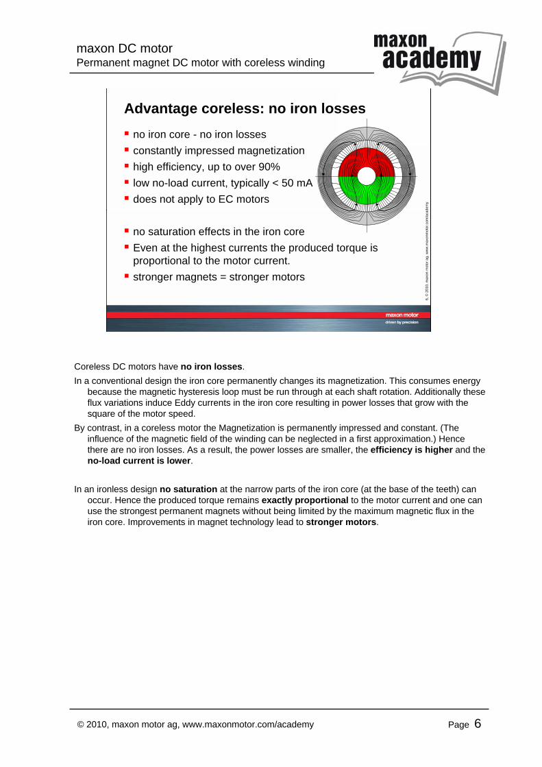
Advantage coreless: no iron lossesno iron core - no iron lossesconstantly impressed magnetizationhigh efficiency, up to over 90%low no-load current, typically < 50 mAdoes not apply to EC motors
no saturation effects in the iron coreEven at the highest currents the produced torque is proportional to the motor current.stronger magnets = stronger motors
Coreless DC motors have no iron losses.In a conventional design the iron core permanently changes its magnetization. This consumes energy
because the magnetic hysteresis loop must be run through at each shaft rotation. Additionally these flux variations induce Eddy currents in the iron core resulting in power losses that grow with the square of the motor speed.
By contrast, in a coreless motor the Magnetization is permanently impressed and constant. (The influence of the magnetic field of the winding can be neglected in a first approximation.) Hence there are no iron losses. As a result, the power losses are smaller, the efficiency is higher and the no-load current is lower.
In an ironless design no saturation at the narrow parts of the iron core (at the base of the teeth) can occur. Hence the produced torque remains exactly proportional to the motor current and one can use the strongest permanent magnets without being limited by the maximum magnetic flux in the iron core. Improvements in magnet technology lead to stronger motors.
maxon DC motorPermanent magnet DC motor with coreless winding
Page 7© 2010, maxon motor ag, www.maxonmotor.com/academy
7, ©
2010
, max
on m
otor
ag,
ww
w.m
axon
mot
or.c
om/a
cade
my
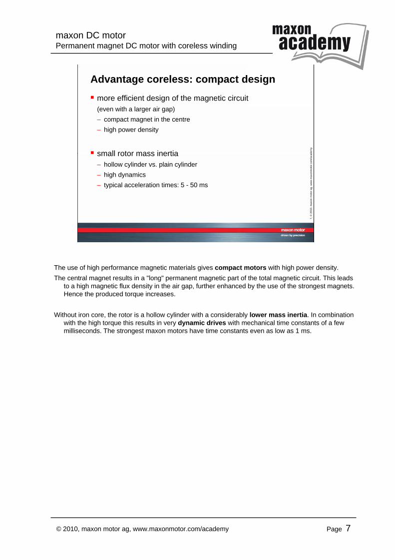
Advantage coreless: compact designmore efficient design of the magnetic circuit(even with a larger air gap)– compact magnet in the centre– high power density
small rotor mass inertia– hollow cylinder vs. plain cylinder– high dynamics– typical acceleration times: 5 - 50 ms
The use of high performance magnetic materials gives compact motors with high power density.The central magnet results in a "long" permanent magnetic part of the total magnetic circuit. This leads
to a high magnetic flux density in the air gap, further enhanced by the use of the strongest magnets. Hence the produced torque increases.
Without iron core, the rotor is a hollow cylinder with a considerably lower mass inertia. In combination with the high torque this results in very dynamic drives with mechanical time constants of a few milliseconds. The strongest maxon motors have time constants even as low as 1 ms.
maxon DC motorPermanent magnet DC motor with coreless winding
Page 8© 2010, maxon motor ag, www.maxonmotor.com/academy
8, ©
2010
, max
on m
otor
ag,
ww
w.m
axon
mot
or.c
om/a
cade
my
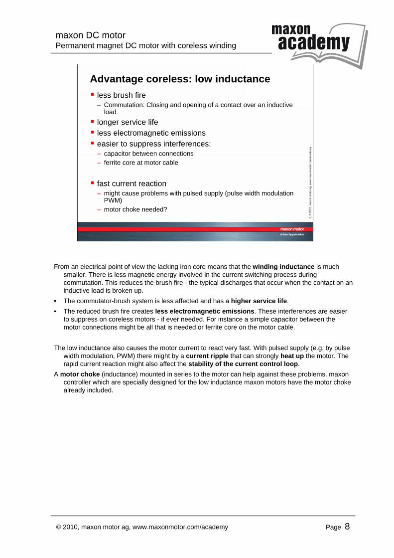
Advantage coreless: low inductanceless brush fire– Commutation: Closing and opening of a contact over an inductive
loadlonger service lifeless electromagnetic emissionseasier to suppress interferences:– capacitor between connections– ferrite core at motor cable
fast current reaction– might cause problems with pulsed supply (pulse width modulation
PWM)– motor choke needed?
From an electrical point of view the lacking iron core means that the winding inductance is much smaller. There is less magnetic energy involved in the current switching process during commutation. This reduces the brush fire - the typical discharges that occur when the contact on an inductive load is broken up.
• The commutator-brush system is less affected and has a higher service life.• The reduced brush fire creates less electromagnetic emissions. These interferences are easier
to suppress on coreless motors - if ever needed. For instance a simple capacitor between the motor connections might be all that is needed or ferrite core on the motor cable.
The low inductance also causes the motor current to react very fast. With pulsed supply (e.g. by pulse width modulation, PWM) there might by a current ripple that can strongly heat up the motor. The rapid current reaction might also affect the stability of the current control loop.
A motor choke (inductance) mounted in series to the motor can help against these problems. maxon controller which are specially designed for the low inductance maxon motors have the motor choke already included.
maxon DC motorPermanent magnet DC motor with coreless winding
Page 9© 2010, maxon motor ag, www.maxonmotor.com/academy
9, ©
2010
, max
on m
otor
ag,
ww
w.m
axon
mot
or.c
om/a
cade
my
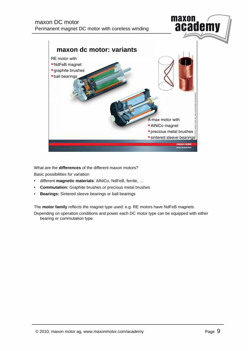
maxon dc motor: variants
A-max motor withAlNiCo magnetprecious metal brushessintered sleeve bearings
RE motor withNdFeB magnetgraphite brushesball bearings
What are the differences of the different maxon motors?Basic possibilities for variation• different magnetic materials: AlNiCo, NdFeB, ferrite, …• Commutation: Graphite brushes or precious metal brushes• Bearings: Sintered sleeve bearings or ball bearings
The motor family reflects the magnet type used: e.g. RE motors have NdFeB magnets.Depending on operation conditions and power each DC motor type can be equipped with either
bearing or commutation type.
maxon DC motorPermanent magnet DC motor with coreless winding
Page 10© 2010, maxon motor ag, www.maxonmotor.com/academy
10, ©
2010
, max
on m
otor
ag,
ww
w.m
axon
mot
or.c
om/a
cade
my
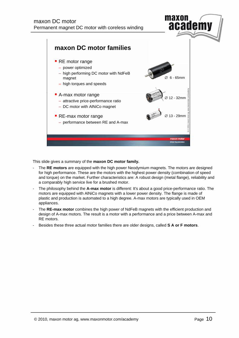
maxon DC motor families
RE motor range– power optimized– high performing DC motor with NdFeB
magnet– high torques and speeds
A-max motor range– attractive price-performance ratio– DC motor with AlNiCo magnet
RE-max motor range– performance between RE and A-max
∅ 6 - 65mm
∅ 12 - 32mm
∅ 13 - 29mm
This slide gives a summary of the maxon DC motor family.- The RE motors are equipped with the high power Neodymium magnets. The motors are designed
for high performance. These are the motors with the highest power density (combination of speed and torque) on the market. Further characteristics are: A robust design (metal flange), reliability and a comparably high service live for a brushed motor.
- The philosophy behind the A-max motor is different: It's about a good price-performance ratio. The motors are equipped with AlNiCo magnets with a lower power density. The flange is made of plastic and production is automated to a high degree. A-max motors are typically used in OEM appliances.
- The RE-max motor combines the high power of NdFeB magnets with the efficient production and design of A-max motors. The result is a motor with a performance and a price between A-max and RE motors.
- Besides these three actual motor families there are older designs, called S A or F motors.
maxon DC motorPermanent magnet DC motor with coreless winding
Page 11© 2010, maxon motor ag, www.maxonmotor.com/academy
11, ©
2010
, max
on m
otor
ag,
ww
w.m
axon
mot
or.c
om/a
cade
my
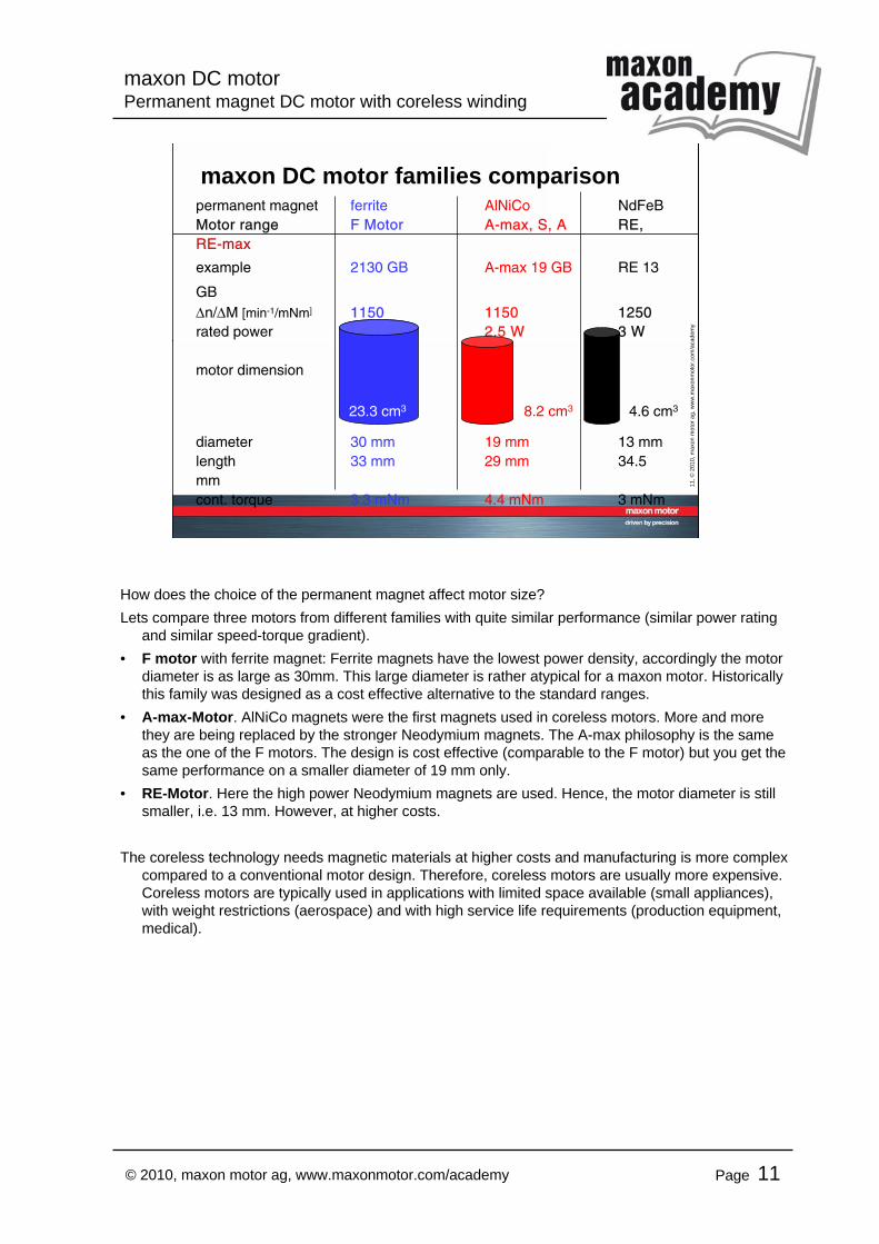
maxon DC motor families comparisonpermanent magnet ferrite AlNiCo NdFeBMotor range F Motor A-max, S, A RE,RE-max
example 2130 GB A-max 19 GB RE 13
GB∆n/∆M [min-1/mNm] 1150 1150 1250rated power 3 W 2.5 W 3 W
motor dimension
diameter 30 mm 19 mm 13 mmlength 33 mm 29 mm 34.5 mmcont. torque 3.3 mNm 4.4 mNm 3 mNm
23.3 cm3 4.6 cm38.2 cm3
How does the choice of the permanent magnet affect motor size?Lets compare three motors from different families with quite similar performance (similar power rating
and similar speed-torque gradient).• F motor with ferrite magnet: Ferrite magnets have the lowest power density, accordingly the motor
diameter is as large as 30mm. This large diameter is rather atypical for a maxon motor. Historically this family was designed as a cost effective alternative to the standard ranges.
• A-max-Motor. AlNiCo magnets were the first magnets used in coreless motors. More and more they are being replaced by the stronger Neodymium magnets. The A-max philosophy is the same as the one of the F motors. The design is cost effective (comparable to the F motor) but you get the same performance on a smaller diameter of 19 mm only.
• RE-Motor. Here the high power Neodymium magnets are used. Hence, the motor diameter is still smaller, i.e. 13 mm. However, at higher costs.
The coreless technology needs magnetic materials at higher costs and manufacturing is more complex compared to a conventional motor design. Therefore, coreless motors are usually more expensive. Coreless motors are typically used in applications with limited space available (small appliances), with weight restrictions (aerospace) and with high service life requirements (production equipment, medical).
maxon DC motorPermanent magnet DC motor with coreless winding
Page 12© 2010, maxon motor ag, www.maxonmotor.com/academy
12, ©
2010
, max
on m
otor
ag,
ww
w.m
axon
mot
or.c
om/a
cade
my
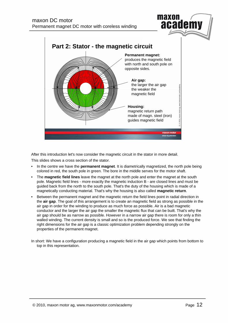
Part 2: Stator - the magnetic circuit
Housing:magnetic return pathmade of magn. steel (iron)guides magnetic field
Air gap:the larger the air gapthe weaker themagnetic field
Permanent magnet:produces the magnetic fieldwith north and south pole onopposite sides.
After this introduction let's now consider the magnetic circuit in the stator in more detail.This slides shows a cross section of the stator.• In the centre we have the permanent magnet. It is diametrically magnetized, the north pole being
colored in red, the south pole in green. The bore in the middle serves for the motor shaft.• The magnetic field lines leave the magnet at the north pole and enter the magnet at the south
pole. Magnetic field lines - more exactly the magnetic induction B - are closed lines and must be guided back from the north to the south pole. That's the duty of the housing which is made of a magnetically conducting material. That's why the housing is also called magnetic return.
• Between the permanent magnet and the magnetic return the field lines point in radial direction in the air gap. The goal of this arrangement is to create an magnetic field as strong as possible in the air gap in order for the winding to produce as much force as possible. Air is a bad magnetic conductor and the larger the air gap the smaller the magnetic flux that can be built. That's why the air gap should be as narrow as possible. However in a narrow air gap there is room for only a thin walled winding. The current density is small and so is the produced force. We see that finding the right dimensions for the air gap is a classic optimization problem depending strongly on the properties of the permanent magnet.
In short: We have a configuration producing a magnetic field in the air gap which points from bottom to top in this representation.
maxon DC motorPermanent magnet DC motor with coreless winding
Page 13© 2010, maxon motor ag, www.maxonmotor.com/academy
13, ©
2010
, max
on m
otor
ag,
ww
w.m
axon
mot
or.c
om/a
cade
my
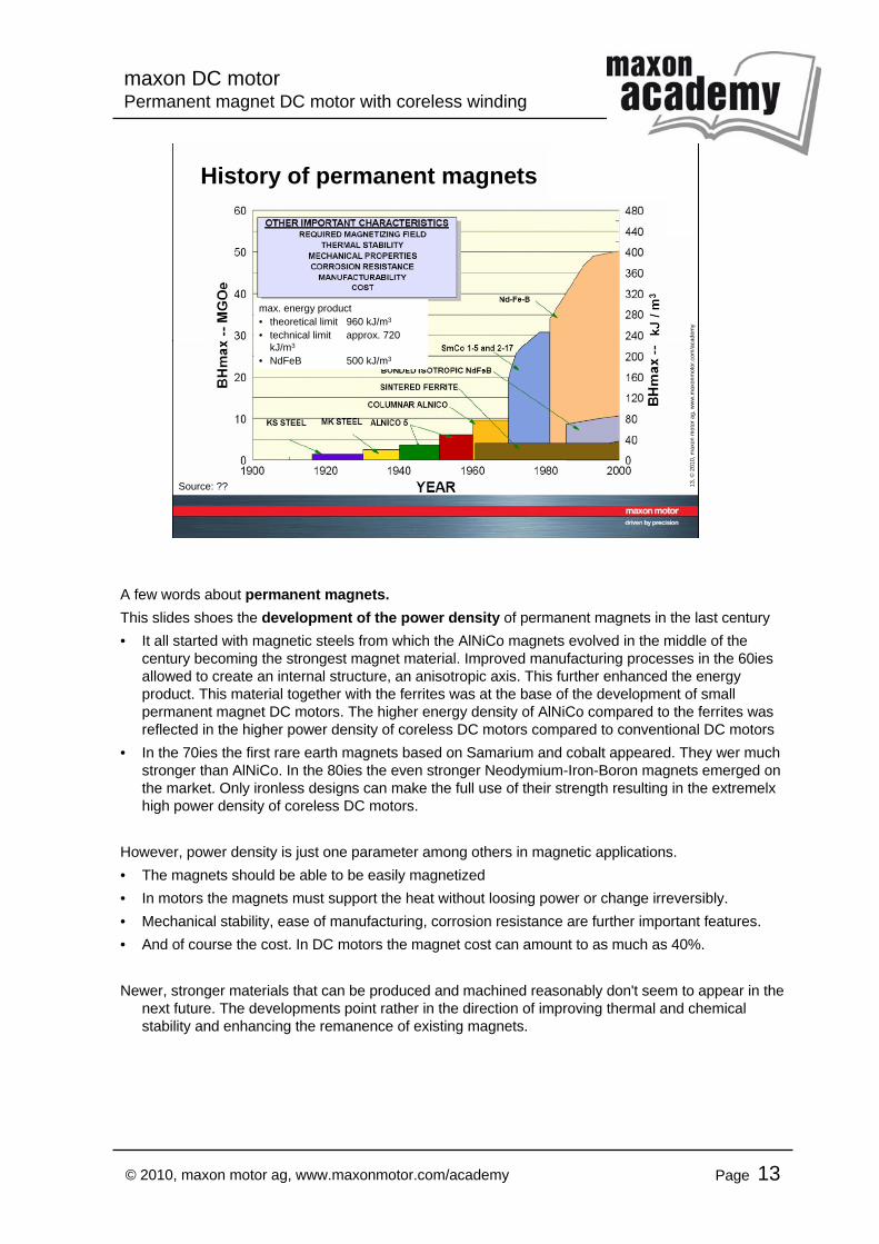
History of permanent magnets
max. energy product• theoretical limit 960 kJ/m3
• technical limit approx. 720 kJ/m3
• NdFeB 500 kJ/m3
Source: ??
A few words about permanent magnets.This slides shoes the development of the power density of permanent magnets in the last century• It all started with magnetic steels from which the AlNiCo magnets evolved in the middle of the
century becoming the strongest magnet material. Improved manufacturing processes in the 60ies allowed to create an internal structure, an anisotropic axis. This further enhanced the energy product. This material together with the ferrites was at the base of the development of small permanent magnet DC motors. The higher energy density of AlNiCo compared to the ferrites was reflected in the higher power density of coreless DC motors compared to conventional DC motors
• In the 70ies the first rare earth magnets based on Samarium and cobalt appeared. They wer much stronger than AlNiCo. In the 80ies the even stronger Neodymium-Iron-Boron magnets emerged on the market. Only ironless designs can make the full use of their strength resulting in the extremelxhigh power density of coreless DC motors.
However, power density is just one parameter among others in magnetic applications.• The magnets should be able to be easily magnetized• In motors the magnets must support the heat without loosing power or change irreversibly.• Mechanical stability, ease of manufacturing, corrosion resistance are further important features.• And of course the cost. In DC motors the magnet cost can amount to as much as 40%.
Newer, stronger materials that can be produced and machined reasonably don't seem to appear in the next future. The developments point rather in the direction of improving thermal and chemical stability and enhancing the remanence of existing magnets.
maxon DC motorPermanent magnet DC motor with coreless winding
Page 14© 2010, maxon motor ag, www.maxonmotor.com/academy
14, ©
2010
, max
on m
otor
ag,
ww
w.m
axon
mot
or.c
om/a
cade
my
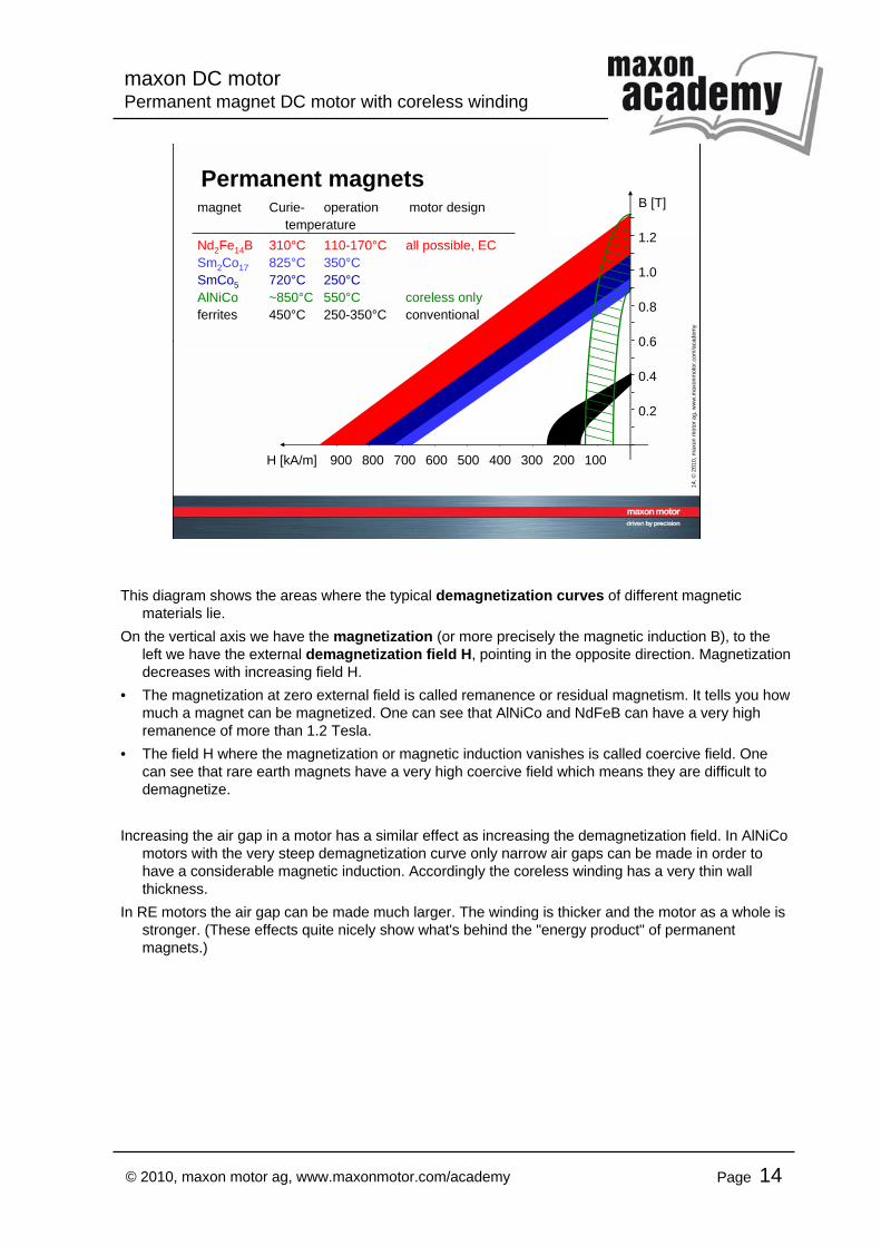
Permanent magnetsB [T]
1.2
1.0
0.8
0.6
0.4
0.2
H [kA/m] 900 800 700 600 500 400 300 200 100
magnet Curie- operation motor designtemperature
Nd2Fe14B 310°C 110-170°C all possible, ECSm2Co17 825°C 350°CSmCo5 720°C 250°CAlNiCo ~850°C 550°C coreless onlyferrites 450°C 250-350°C conventional
This diagram shows the areas where the typical demagnetization curves of different magnetic materials lie.
On the vertical axis we have the magnetization (or more precisely the magnetic induction B), to the left we have the external demagnetization field H, pointing in the opposite direction. Magnetization decreases with increasing field H.
• The magnetization at zero external field is called remanence or residual magnetism. It tells you how much a magnet can be magnetized. One can see that AlNiCo and NdFeB can have a very high remanence of more than 1.2 Tesla.
• The field H where the magnetization or magnetic induction vanishes is called coercive field. One can see that rare earth magnets have a very high coercive field which means they are difficult to demagnetize.
Increasing the air gap in a motor has a similar effect as increasing the demagnetization field. In AlNiCo motors with the very steep demagnetization curve only narrow air gaps can be made in order to have a considerable magnetic induction. Accordingly the coreless winding has a very thin wall thickness.
In RE motors the air gap can be made much larger. The winding is thicker and the motor as a whole is stronger. (These effects quite nicely show what's behind the "energy product" of permanent magnets.)
maxon DC motorPermanent magnet DC motor with coreless winding
Page 15© 2010, maxon motor ag, www.maxonmotor.com/academy
15, ©
2010
, max
on m
otor
ag,
ww
w.m
axon
mot
or.c
om/a
cade
my
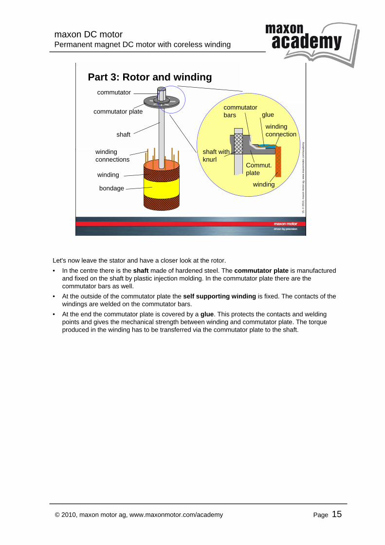
Part 3: Rotor and winding
commutator plate
commutator
windingconnections
winding
shaft
Commut.plate
winding
commutatorbars
windingconnection
glue
shaft withknurl
bondage
Let's now leave the stator and have a closer look at the rotor.• In the centre there is the shaft made of hardened steel. The commutator plate is manufactured
and fixed on the shaft by plastic injection molding. In the commutator plate there are the commutator bars as well.
• At the outside of the commutator plate the self supporting winding is fixed. The contacts of the windings are welded on the commutator bars.
• At the end the commutator plate is covered by a glue. This protects the contacts and welding points and gives the mechanical strength between winding and commutator plate. The torque produced in the winding has to be transferred via the commutator plate to the shaft.
maxon DC motorPermanent magnet DC motor with coreless winding
Page 16© 2010, maxon motor ag, www.maxonmotor.com/academy
16, ©
2010
, max
on m
otor
ag,
ww
w.m
axon
mot
or.c
om/a
cade
my
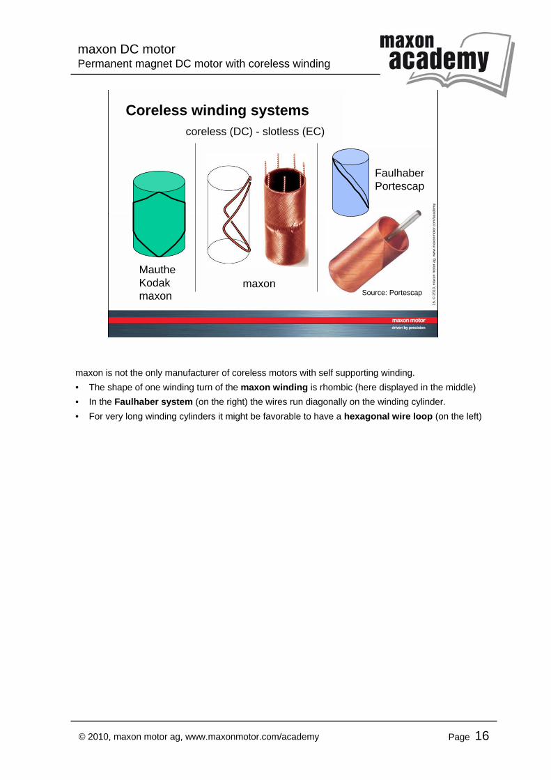
Coreless winding systems
maxon
FaulhaberPortescap
Source: Portescap
MautheKodakmaxon
coreless (DC) - slotless (EC)
maxon is not the only manufacturer of coreless motors with self supporting winding.• The shape of one winding turn of the maxon winding is rhombic (here displayed in the middle)• In the Faulhaber system (on the right) the wires run diagonally on the winding cylinder.• For very long winding cylinders it might be favorable to have a hexagonal wire loop (on the left)
maxon DC motorPermanent magnet DC motor with coreless winding
Page 17© 2010, maxon motor ag, www.maxonmotor.com/academy
17, ©
2010
, max
on m
otor
ag,
ww
w.m
axon
mot
or.c
om/a
cade
my
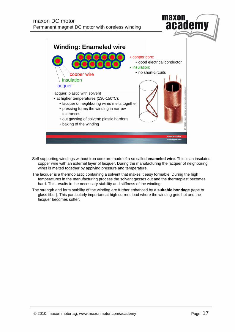
Winding: Enameled wire
lacquer: plastic with solvent• at higher temperatures (130-150°C):
• lacquer of neighboring wires melts together• pressing forms the winding in narrow
tolerances• out gassing of solvent: plastic hardens• baking of the winding
copper wire
lacquerinsulation
• copper core: • good electrical conductor
• insulation: • no short-circuits
Self supporting windings without iron core are made of a so called enameled wire. This is an insulated copper wire with an external layer of lacquer. During the manufacturing the lacquer of neighboring wires is melted together by applying pressure and temperature.
The lacquer is a thermoplastic containing a solvent that makes it easy formable. During the high temperatures in the manufacturing process the solvant gasses out and the thermoplast becomes hard. This results in the necessary stability and stiffness of the winding.
The strength and form stability of the winding are further enhanced by a suitable bondage (tape or glass fiber). This particularly important at high current load where the winding gets hot and the lacquer becomes softer.
maxon DC motorPermanent magnet DC motor with coreless winding
Page 18© 2010, maxon motor ag, www.maxonmotor.com/academy
18, ©
2010
, max
on m
otor
ag,
ww
w.m
axon
mot
or.c
om/a
cade
my
"knitted" maxon winding
"knitted" winding for• large motors with NdFeB magnet• RE motors, EC motors• thick-walled windings
standard maxon winding
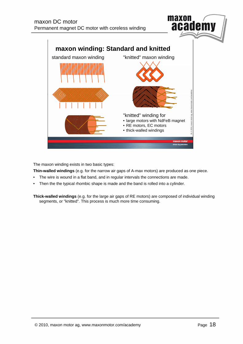
maxon winding: Standard and knitted
The maxon winding exists in two basic types:Thin-walled windings (e.g. for the narrow air gaps of A-max motors) are produced as one piece.• The wire is wound in a flat band, and in regular intervals the connections are made. • Then the the typical rhombic shape is made and the band is rolled into a cylinder.
Thick-walled windings (e.g. for the large air gaps of RE motors) are composed of individual winding segments, or "knitted". This process is much more time consuming.
maxon DC motorPermanent magnet DC motor with coreless winding
Page 19© 2010, maxon motor ag, www.maxonmotor.com/academy
19, ©
2010
, max
on m
otor
ag,
ww
w.m
axon
mot
or.c
om/a
cade
my
Current flow through the maxon winding1 2 3 4 5 6 7 8 9 1
1 2 3 4 5 5 6 7 8 9 1
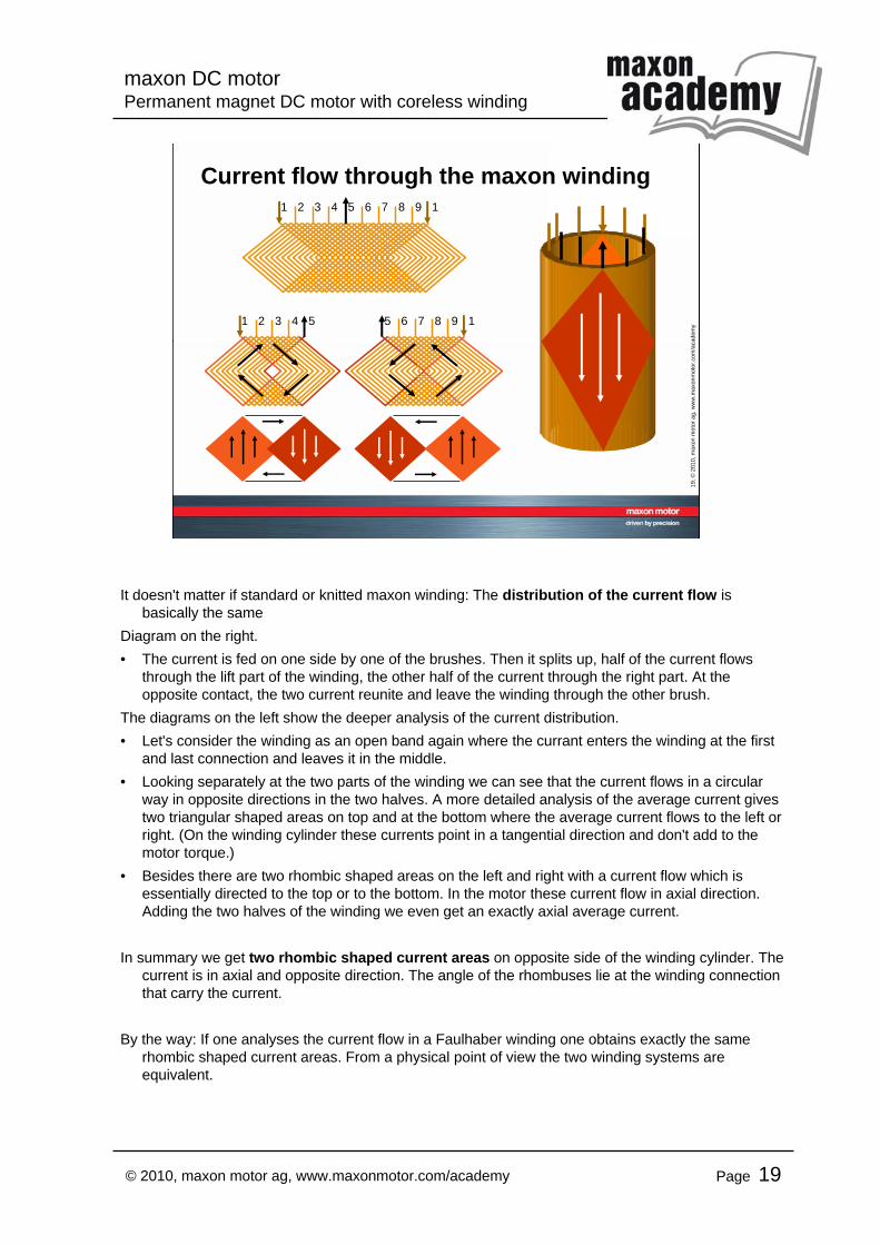
It doesn't matter if standard or knitted maxon winding: The distribution of the current flow is basically the same
Diagram on the right.• The current is fed on one side by one of the brushes. Then it splits up, half of the current flows
through the lift part of the winding, the other half of the current through the right part. At the opposite contact, the two current reunite and leave the winding through the other brush.
The diagrams on the left show the deeper analysis of the current distribution.• Let's consider the winding as an open band again where the currant enters the winding at the first
and last connection and leaves it in the middle.• Looking separately at the two parts of the winding we can see that the current flows in a circular
way in opposite directions in the two halves. A more detailed analysis of the average current gives two triangular shaped areas on top and at the bottom where the average current flows to the left or right. (On the winding cylinder these currents point in a tangential direction and don't add to the motor torque.)
• Besides there are two rhombic shaped areas on the left and right with a current flow which is essentially directed to the top or to the bottom. In the motor these current flow in axial direction. Adding the two halves of the winding we even get an exactly axial average current.
In summary we get two rhombic shaped current areas on opposite side of the winding cylinder. The current is in axial and opposite direction. The angle of the rhombuses lie at the winding connection that carry the current.
By the way: If one analyses the current flow in a Faulhaber winding one obtains exactly the same rhombic shaped current areas. From a physical point of view the two winding systems are equivalent.
maxon DC motorPermanent magnet DC motor with coreless winding
Page 20© 2010, maxon motor ag, www.maxonmotor.com/academy
20, ©
2010
, max
on m
otor
ag,
ww
w.m
axon
mot
or.c
om/a
cade
my
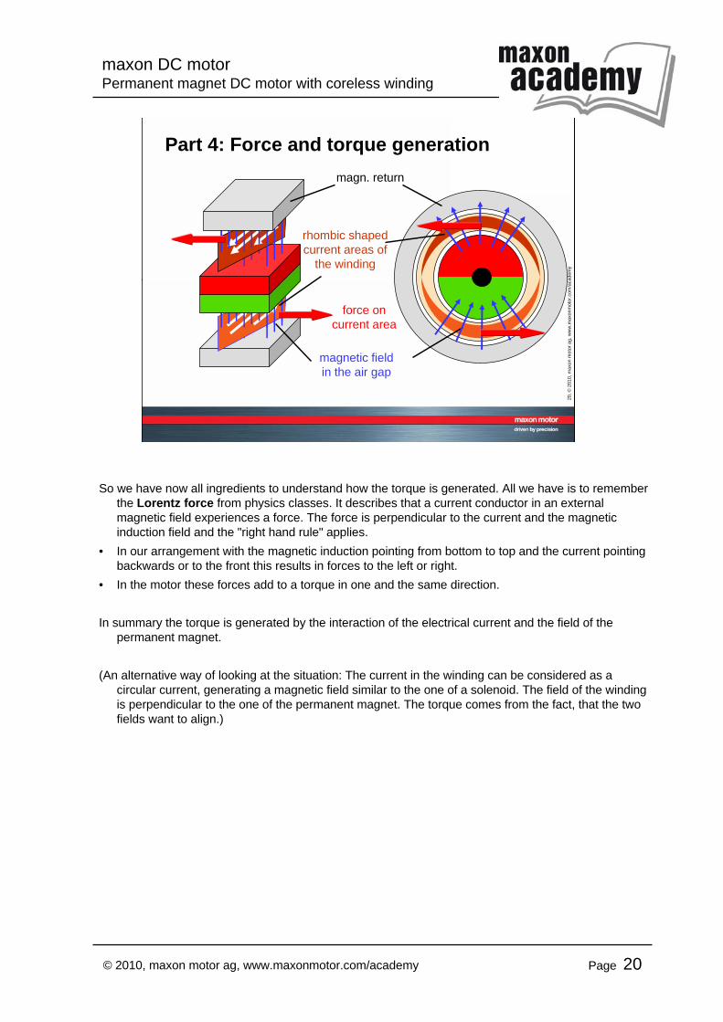
Part 4: Force and torque generation
rhombic shaped current areas of
the winding
magnetic fieldin the air gap
magn. return
force oncurrent area
So we have now all ingredients to understand how the torque is generated. All we have is to remember the Lorentz force from physics classes. It describes that a current conductor in an external magnetic field experiences a force. The force is perpendicular to the current and the magnetic induction field and the "right hand rule" applies.
• In our arrangement with the magnetic induction pointing from bottom to top and the current pointing backwards or to the front this results in forces to the left or right.
• In the motor these forces add to a torque in one and the same direction.
In summary the torque is generated by the interaction of the electrical current and the field of the permanent magnet.
(An alternative way of looking at the situation: The current in the winding can be considered as a circular current, generating a magnetic field similar to the one of a solenoid. The field of the winding is perpendicular to the one of the permanent magnet. The torque comes from the fact, that the two fields want to align.)
maxon DC motorPermanent magnet DC motor with coreless winding
Page 21© 2010, maxon motor ag, www.maxonmotor.com/academy
21, ©
2010
, max
on m
otor
ag,
ww
w.m
axon
mot
or.c
om/a
cade
my
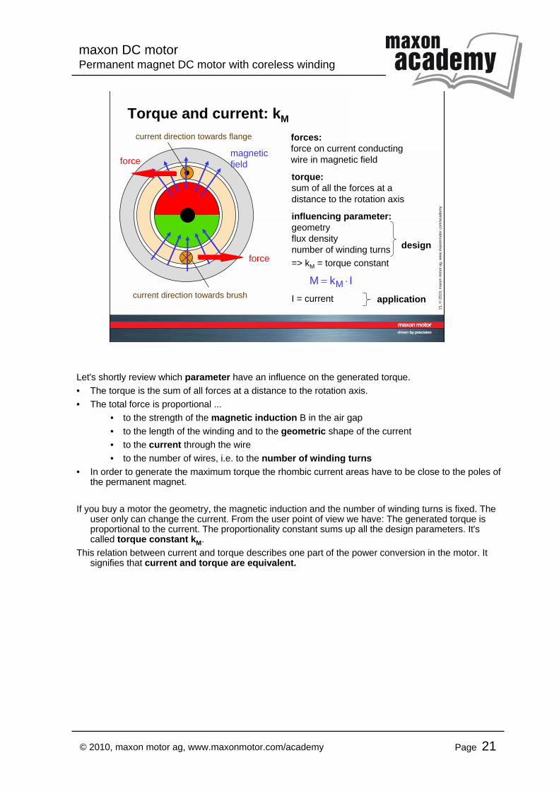
Torque and current: kM
forces:force on current conducting wire in magnetic field
torque:sum of all the forces at a distance to the rotation axis
influencing parameter:geometryflux densitynumber of winding turns=> kM = torque constant
I = current
design
application
IkM M ⋅=
current direction towards flange
force
force
current direction towards brush
magneticfield
Let's shortly review which parameter have an influence on the generated torque.• The torque is the sum of all forces at a distance to the rotation axis.• The total force is proportional ...
• to the strength of the magnetic induction B in the air gap• to the length of the winding and to the geometric shape of the current• to the current through the wire• to the number of wires, i.e. to the number of winding turns
• In order to generate the maximum torque the rhombic current areas have to be close to the poles of the permanent magnet.
If you buy a motor the geometry, the magnetic induction and the number of winding turns is fixed. The user only can change the current. From the user point of view we have: The generated torque is proportional to the current. The proportionality constant sums up all the design parameters. It's called torque constant kM.
This relation between current and torque describes one part of the power conversion in the motor. It signifies that current and torque are equivalent.
maxon DC motorPermanent magnet DC motor with coreless winding
Page 22© 2010, maxon motor ag, www.maxonmotor.com/academy
22, ©
2010
, max
on m
otor
ag,
ww
w.m
axon
mot
or.c
om/a
cade
my
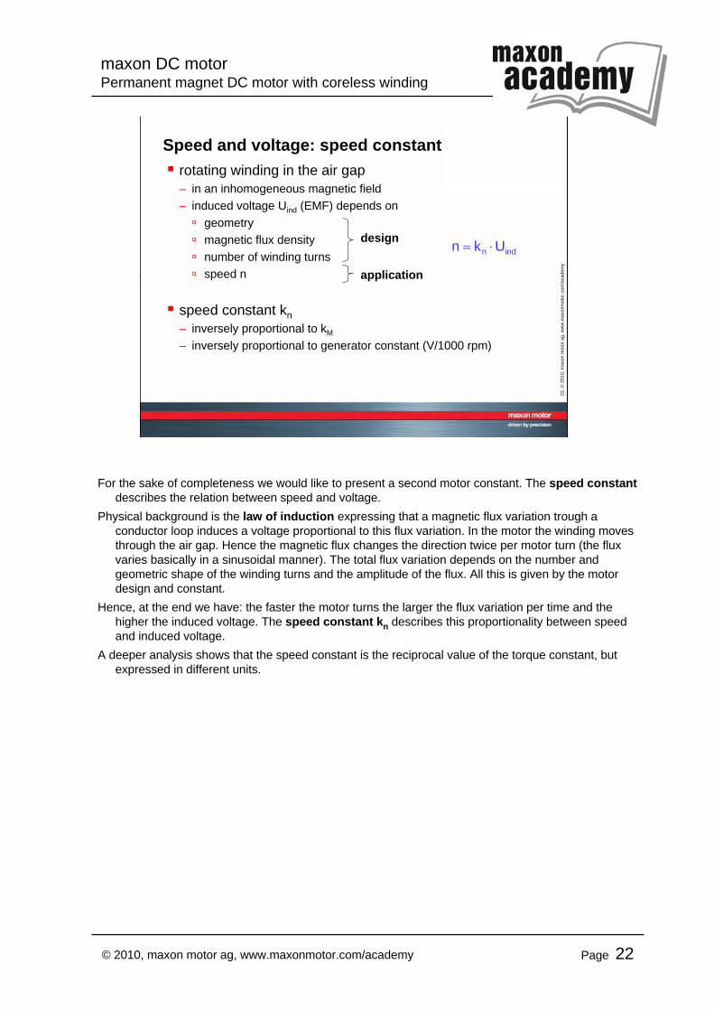
Speed and voltage: speed constantrotating winding in the air gap– in an inhomogeneous magnetic field– induced voltage Uind (EMF) depends on
geometrymagnetic flux densitynumber of winding turnsspeed n
speed constant kn– inversely proportional to kM
– inversely proportional to generator constant (V/1000 rpm)
indn Ukn ⋅=design
application
For the sake of completeness we would like to present a second motor constant. The speed constantdescribes the relation between speed and voltage.
Physical background is the law of induction expressing that a magnetic flux variation trough a conductor loop induces a voltage proportional to this flux variation. In the motor the winding moves through the air gap. Hence the magnetic flux changes the direction twice per motor turn (the flux varies basically in a sinusoidal manner). The total flux variation depends on the number and geometric shape of the winding turns and the amplitude of the flux. All this is given by the motor design and constant.
Hence, at the end we have: the faster the motor turns the larger the flux variation per time and the higher the induced voltage. The speed constant kn describes this proportionality between speed and induced voltage.
A deeper analysis shows that the speed constant is the reciprocal value of the torque constant, but expressed in different units.
maxon DC motorPermanent magnet DC motor with coreless winding
Page 23© 2010, maxon motor ag, www.maxonmotor.com/academy
23, ©
2010
, max
on m
otor
ag,
ww
w.m
axon
mot
or.c
om/a
cade
my
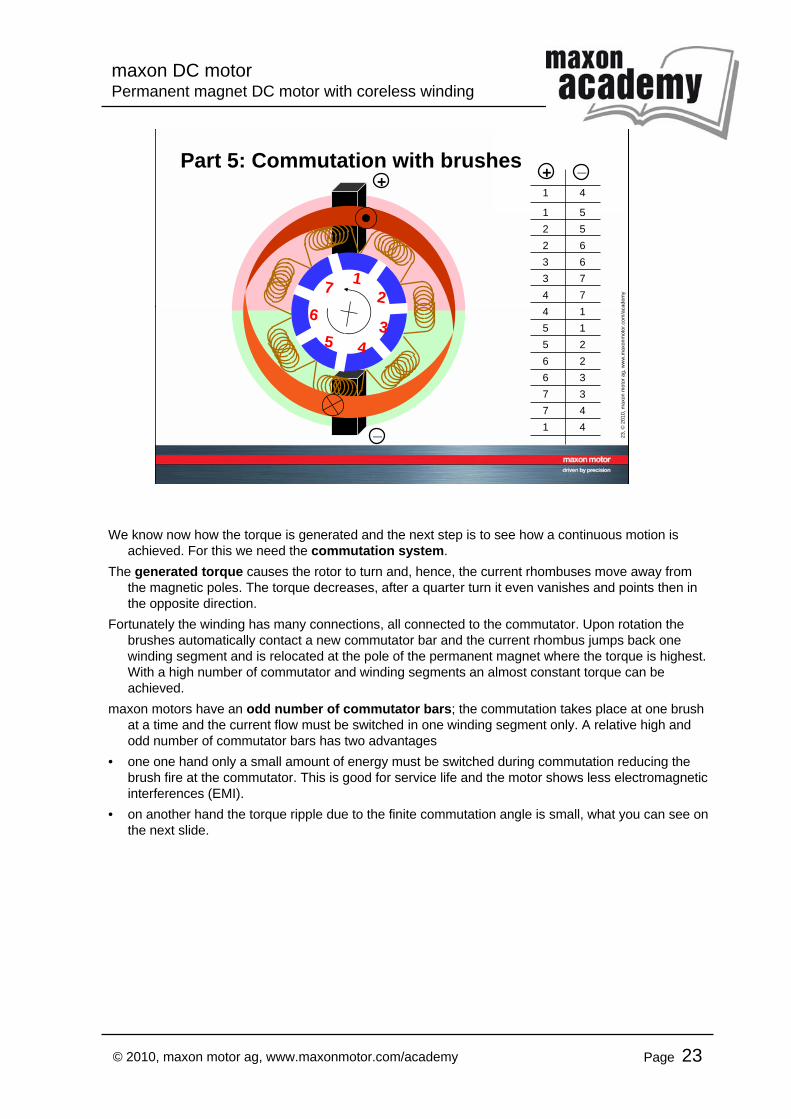
Part 5: Commutation with brushes _++
_
1 4
1 52 52 63 63 74 74 15 15 26 26 37 37 41 4
12
345
67
We know now how the torque is generated and the next step is to see how a continuous motion is achieved. For this we need the commutation system.
The generated torque causes the rotor to turn and, hence, the current rhombuses move away from the magnetic poles. The torque decreases, after a quarter turn it even vanishes and points then in the opposite direction.
Fortunately the winding has many connections, all connected to the commutator. Upon rotation the brushes automatically contact a new commutator bar and the current rhombus jumps back one winding segment and is relocated at the pole of the permanent magnet where the torque is highest. With a high number of commutator and winding segments an almost constant torque can be achieved.
maxon motors have an odd number of commutator bars; the commutation takes place at one brush at a time and the current flow must be switched in one winding segment only. A relative high and odd number of commutator bars has two advantages
• one one hand only a small amount of energy must be switched during commutation reducing the brush fire at the commutator. This is good for service life and the motor shows less electromagnetic interferences (EMI).
• on another hand the torque ripple due to the finite commutation angle is small, what you can see on the next slide.
maxon DC motorPermanent magnet DC motor with coreless winding
Page 24© 2010, maxon motor ag, www.maxonmotor.com/academy
24, ©
2010
, max
on m
otor
ag,
ww
w.m
axon
mot
or.c
om/a
cade
my
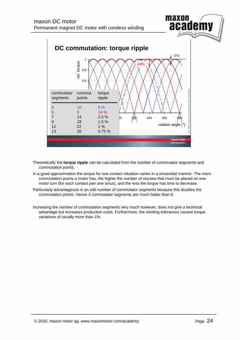
DC commutation: torque ripple
0
0.2
0.4
0.6
0.8
1
0 60 120 180 240 300 360
rotation angle (°)
rel.
torq
ue
commutator commut. torquesegments points ripple
5 10 5 %6 6 14 %7 14 2.5 %9 18 1.5 %11 22 1 %13 26 0.75 %
5%
14%
Theoretically the torque ripple can be calculated from the number of commutator segments and commutation points.
In a good approximation the torque for one contact situation varies in a sinusoidal manner. The more commutation points a motor has, the higher the number of sinuses that must be placed on one motor turn (for each contact pair one sinus), and the less the torque has time to decrease.
Particularly advantageous is an odd number of commutator segments because this doubles the commutation points. Hence 5 commutator segments are much better than 6.
Increasing the number of commutation segments very much however, does not give a technical advantage but increases production costs. Furthermore, the winding tolerances causes torque variations of usually more than 1%.
maxon DC motorPermanent magnet DC motor with coreless winding
Page 25© 2010, maxon motor ag, www.maxonmotor.com/academy
25, ©
2010
, max
on m
otor
ag,
ww
w.m
axon
mot
or.c
om/a
cade
my
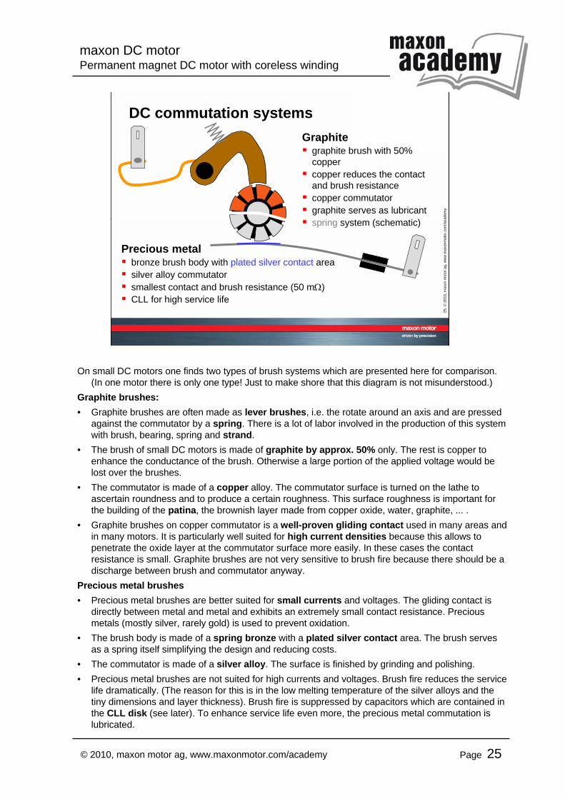
DC commutation systems
Precious metalbronze brush body with plated silver contact areasilver alloy commutatorsmallest contact and brush resistance (50 mΩ)CLL for high service life
Graphitegraphite brush with 50% coppercopper reduces the contact and brush resistancecopper commutatorgraphite serves as lubricantspring system (schematic)
On small DC motors one finds two types of brush systems which are presented here for comparison. (In one motor there is only one type! Just to make shore that this diagram is not misunderstood.)
Graphite brushes:• Graphite brushes are often made as lever brushes, i.e. the rotate around an axis and are pressed
against the commutator by a spring. There is a lot of labor involved in the production of this system with brush, bearing, spring and strand.
• The brush of small DC motors is made of graphite by approx. 50% only. The rest is copper to enhance the conductance of the brush. Otherwise a large portion of the applied voltage would be lost over the brushes.
• The commutator is made of a copper alloy. The commutator surface is turned on the lathe to ascertain roundness and to produce a certain roughness. This surface roughness is important for the building of the patina, the brownish layer made from copper oxide, water, graphite, ... .
• Graphite brushes on copper commutator is a well-proven gliding contact used in many areas and in many motors. It is particularly well suited for high current densities because this allows to penetrate the oxide layer at the commutator surface more easily. In these cases the contact resistance is small. Graphite brushes are not very sensitive to brush fire because there should be a discharge between brush and commutator anyway.
Precious metal brushes• Precious metal brushes are better suited for small currents and voltages. The gliding contact is
directly between metal and metal and exhibits an extremely small contact resistance. Precious metals (mostly silver, rarely gold) is used to prevent oxidation.
• The brush body is made of a spring bronze with a plated silver contact area. The brush serves as a spring itself simplifying the design and reducing costs.
• The commutator is made of a silver alloy. The surface is finished by grinding and polishing.• Precious metal brushes are not suited for high currents and voltages. Brush fire reduces the service
life dramatically. (The reason for this is in the low melting temperature of the silver alloys and the tiny dimensions and layer thickness). Brush fire is suppressed by capacitors which are contained in the CLL disk (see later). To enhance service life even more, the precious metal commutation is lubricated.
maxon DC motorPermanent magnet DC motor with coreless winding
Page 26© 2010, maxon motor ag, www.maxonmotor.com/academy
26, ©
2010
, max
on m
otor
ag,
ww
w.m
axon
mot
or.c
om/a
cade
my
DC commutation: rotors
glass fibre bondage
copper commutator
tape bondage
CLL disk
silver commutator
2 shaft ends
precious metal
graphite
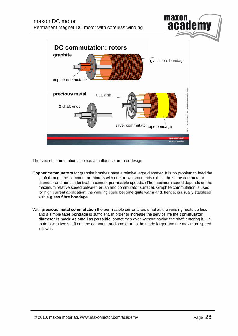
The type of commutation also has an influence on rotor design
Copper commutators for graphite brushes have a relative large diameter. It is no problem to feed the shaft through the commutator. Motors with one or two shaft ends exhibit the same commutatordiameter and hence identical maximum permissible speeds. (The maximum speed depends on the maximum relative speed between brush and commutator surface). Graphite commutation is used for high current application; the winding could become quite warm and, hence, is usually stabilized with a glass fibre bondage.
With precious metal commutation the permissible currents are smaller, the winding heats up lessand a simple tape bondage is sufficient. In order to increase the service life the commutatordiameter is made as small as possible, sometimes even without having the shaft entering it. On motors with two shaft end the commutator diameter must be made larger und the maximum speed is lower.
maxon DC motorPermanent magnet DC motor with coreless winding
Page 27© 2010, maxon motor ag, www.maxonmotor.com/academy
27, ©
2010
, max
on m
otor
ag,
ww
w.m
axon
mot
or.c
om/a
cade
my
DC commutation: terminal resistance
Rwind
IA current
Rmot
IA current
terminalresistance
Rmot
Rwind
Rmot (I)
precious metal
graphite
~50 mΩ
terminalresistance
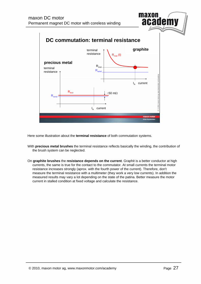
Here some illustration about the terminal resistance of both commutation systems.
With precious metal brushes the terminal resistance reflects basically the winding, the contribution of the brush system can be neglected.
On graphite brushes the resistance depends on the current. Graphit is a better conductor at high currents, the same is true for the contact to the commutator. At small currents the terminal motor resistance increases strongly (aprox. with the fourth power of the current). Therefore, don't measure the terminal resistance with a multimeter (they work a very low currents). In addition the measured results may vary a lot depending on the state of the patina. Better measure the motor current in stalled condition at fixed voltage and calculate the resistance.
maxon DC motorPermanent magnet DC motor with coreless winding
Page 28© 2010, maxon motor ag, www.maxonmotor.com/academy
28, ©
2010
, max
on m
otor
ag,
ww
w.m
axon
mot
or.c
om/a
cade
my
the problem
solution- capacitors between neighbouring
commutator segments- energy is deviated into capacitor:
no arcs produced
Precious metal brushes: CLL
aftershort circuit
arc productioncommutatorwears off
RS
C
commutator
CLL disc
C
C
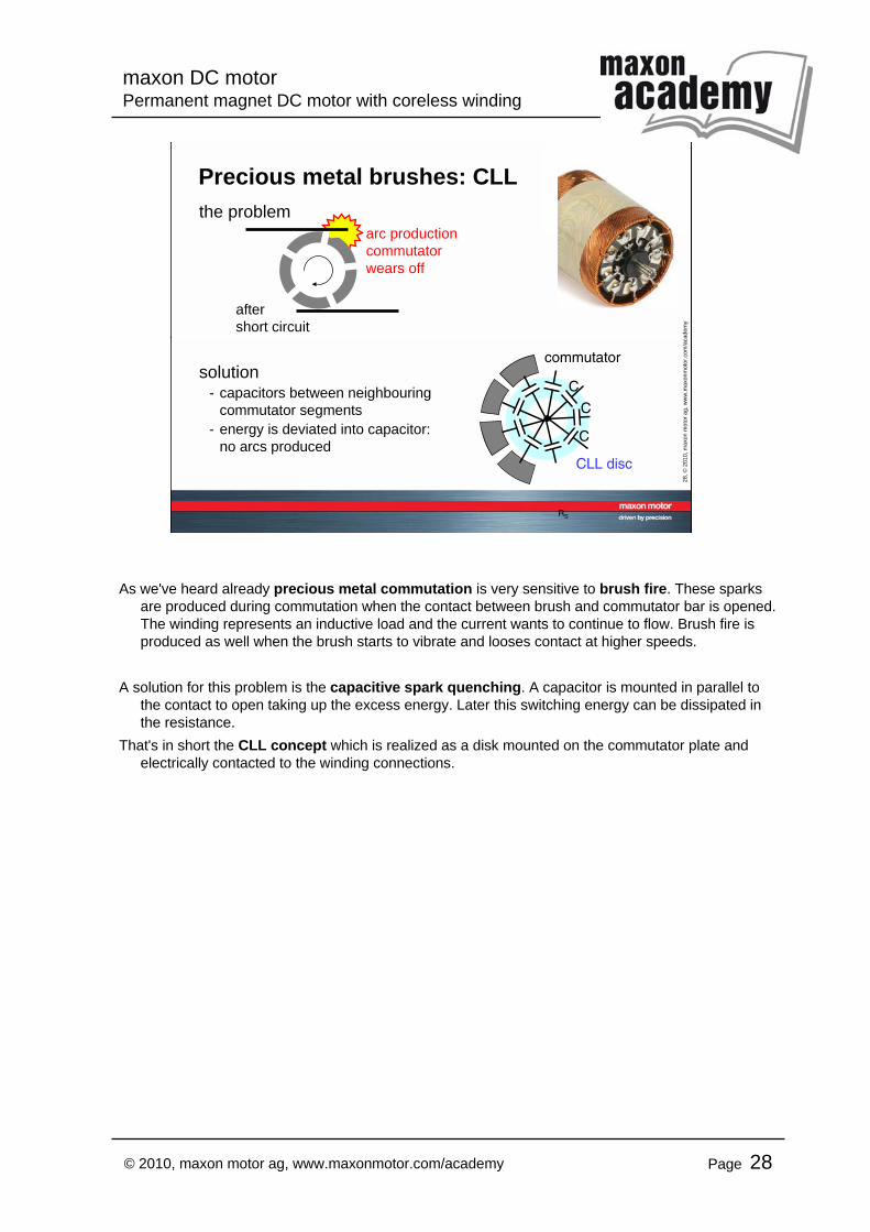
As we've heard already precious metal commutation is very sensitive to brush fire. These sparks are produced during commutation when the contact between brush and commutator bar is opened. The winding represents an inductive load and the current wants to continue to flow. Brush fire is produced as well when the brush starts to vibrate and looses contact at higher speeds.
A solution for this problem is the capacitive spark quenching. A capacitor is mounted in parallel to the contact to open taking up the excess energy. Later this switching energy can be dissipated in the resistance.
That's in short the CLL concept which is realized as a disk mounted on the commutator plate and electrically contacted to the winding connections.
maxon DC motorPermanent magnet DC motor with coreless winding
Page 29© 2010, maxon motor ag, www.maxonmotor.com/academy
29, ©
2010
, max
on m
otor
ag,
ww
w.m
axon
mot
or.c
om/a
cade
my
Precious metal commutation: CLL
time
short-circuitphase
after short-circuit
without CLL:• energy is released rapidly• high voltages, sparks
with CLL:• energy is released slowly• dampened oscillation• small voltages
10 V
200 V
voltagebetween
commutatorbars
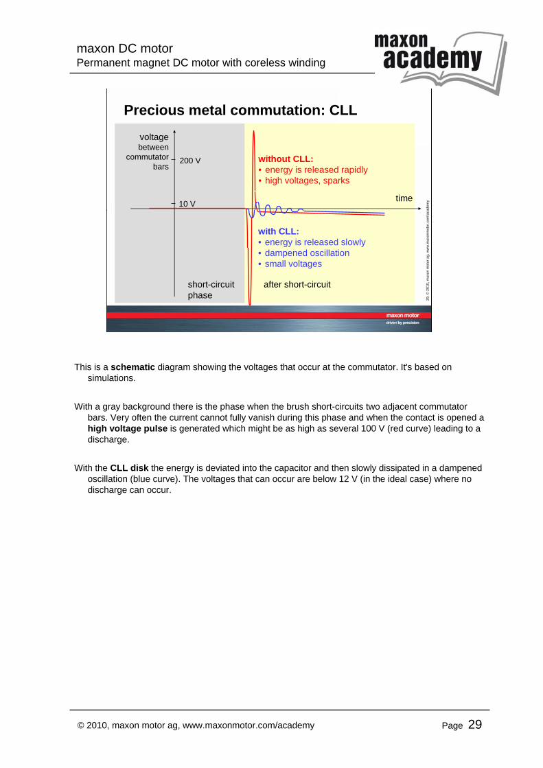
This is a schematic diagram showing the voltages that occur at the commutator. It's based on simulations.
With a gray background there is the phase when the brush short-circuits two adjacent commutatorbars. Very often the current cannot fully vanish during this phase and when the contact is opened a high voltage pulse is generated which might be as high as several 100 V (red curve) leading to a discharge.
With the CLL disk the energy is deviated into the capacitor and then slowly dissipated in a dampened oscillation (blue curve). The voltages that can occur are below 12 V (in the ideal case) where no discharge can occur.
maxon DC motorPermanent magnet DC motor with coreless winding
Page 30© 2010, maxon motor ag, www.maxonmotor.com/academy
30, ©
2010
, max
on m
otor
ag,
ww
w.m
axon
mot
or.c
om/a
cade
my
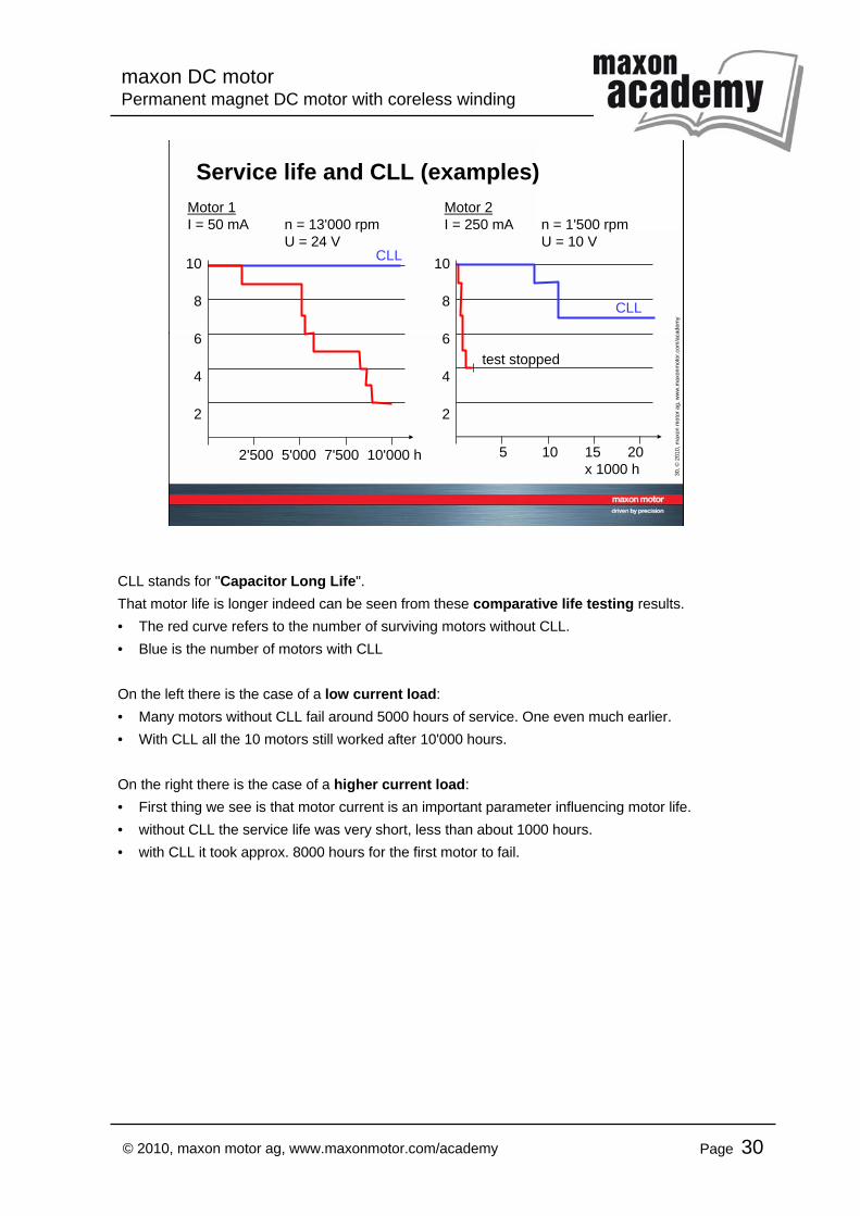
Service life and CLL (examples)
2'500 5'000 7'500 10'000 h
Motor 1I = 50 mA n = 13'000 rpm
U = 24 V10
8
6
4
2
CLL
test stopped
5 10 15 20 x 1000 h
10
8
6
4
2
CLL
Motor 2I = 250 mA n = 1'500 rpm
U = 10 V
CLL stands for "Capacitor Long Life".That motor life is longer indeed can be seen from these comparative life testing results.• The red curve refers to the number of surviving motors without CLL.• Blue is the number of motors with CLL
On the left there is the case of a low current load:• Many motors without CLL fail around 5000 hours of service. One even much earlier.• With CLL all the 10 motors still worked after 10'000 hours.
On the right there is the case of a higher current load:• First thing we see is that motor current is an important parameter influencing motor life.• without CLL the service life was very short, less than about 1000 hours.• with CLL it took approx. 8000 hours for the first motor to fail.
maxon DC motorPermanent magnet DC motor with coreless winding
Page 31© 2010, maxon motor ag, www.maxonmotor.com/academy
31, ©
2010
, max
on m
otor
ag,
ww
w.m
axon
mot
or.c
om/a
cade
my
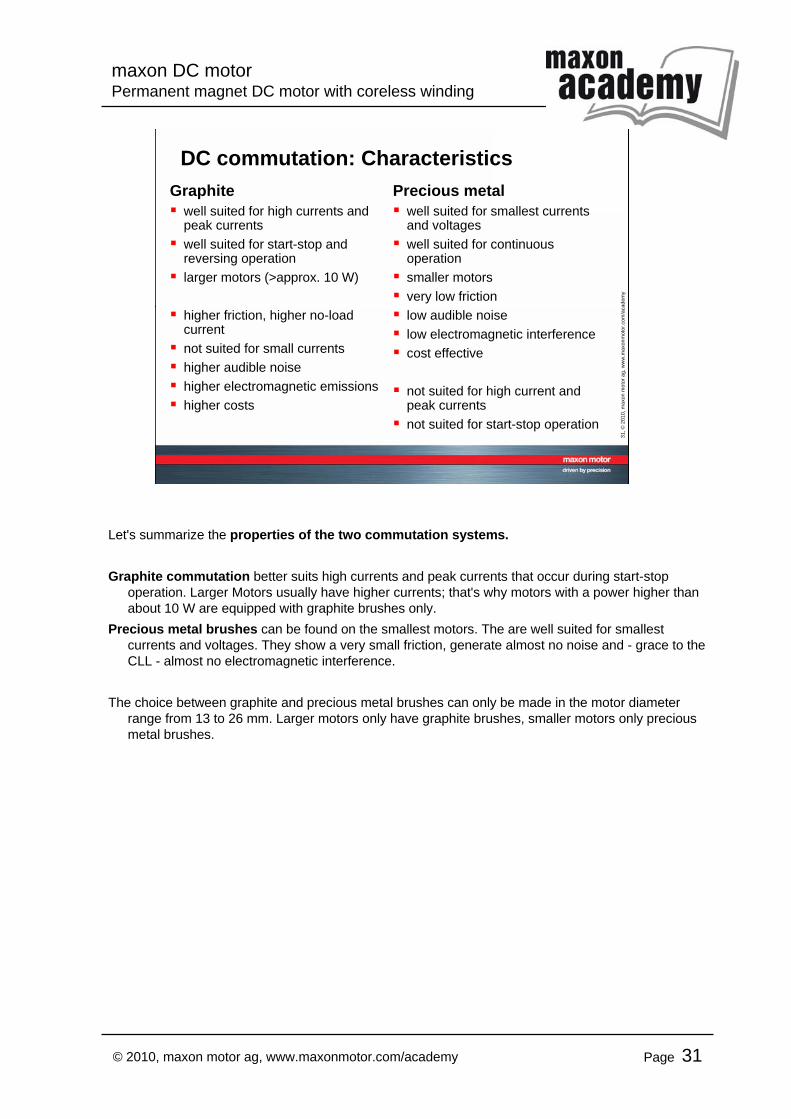
DC commutation: CharacteristicsGraphite
well suited for high currents and peak currents well suited for start-stop and reversing operationlarger motors (>approx. 10 W)
higher friction, higher no-load currentnot suited for small currentshigher audible noisehigher electromagnetic emissionshigher costs
Precious metalwell suited for smallest currents and voltageswell suited for continuous operationsmaller motorsvery low frictionlow audible noiselow electromagnetic interferencecost effective
not suited for high current and peak currentsnot suited for start-stop operation
Let's summarize the properties of the two commutation systems.
Graphite commutation better suits high currents and peak currents that occur during start-stop operation. Larger Motors usually have higher currents; that's why motors with a power higher than about 10 W are equipped with graphite brushes only.
Precious metal brushes can be found on the smallest motors. The are well suited for smallest currents and voltages. They show a very small friction, generate almost no noise and - grace to the CLL - almost no electromagnetic interference.
The choice between graphite and precious metal brushes can only be made in the motor diameter range from 13 to 26 mm. Larger motors only have graphite brushes, smaller motors only precious metal brushes.
maxon DC motorPermanent magnet DC motor with coreless winding
Page 32© 2010, maxon motor ag, www.maxonmotor.com/academy
32, ©
2010
, max
on m
otor
ag,
ww
w.m
axon
mot
or.c
om/a
cade
my
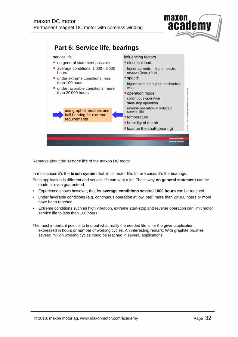
Part 6: Service life, bearingsservice life
no general statement possibleaverage conditions: 1'000 - 3'000 hoursunder extreme conditions: less than 100 hoursunder favorable conditions: more than 20'000 hours
use graphite brushes and ball bearing for extreme requirements
influencing factorselectrical load:higher currents = higher electro erosion (brush fire)speed:higher speed = higher mechanical wearoperation mode:continuous operationstart-stop operationreverse operation = reduced service lifetemperaturehumidity of the airload on the shaft (bearing)
Remarks about the service life of the maxon DC motor
In most cases it's the brush system that limits motor life. In rare cases it's the bearings.Each application is different and service life can vary a lot. That's why no general statement can be
made or even guaranteed.• Experience shows however, that for average conditions several 1000 hours can be reached..• under favorable conditions (e.g. continuous operation at low load) more than 20'000 hours or more
have been reached.• Extreme conditions such as high vibration, extreme start-stop and reverse operation can limit motor
service life to less than 100 hours.
The most important point is to find out what really the needed life is for the given application, expressed in hours or number of working cycles. An interesting remark: With graphite brushes several million working cycles could be reached in several applications.
maxon DC motorPermanent magnet DC motor with coreless winding
Page 33© 2010, maxon motor ag, www.maxonmotor.com/academy
33, ©
2010
, max
on m
otor
ag,
ww
w.m
axon
mot
or.c
om/a
cade
my
Service life estimationsNumber of operating hours– examples
Number of working cycles– examples
Examples for life calculations in operating hours• mixing household appliance: 10 min/week during 40 years …• car: 200'000 km at 50 km/h on average …• fan in laptop or PC ...• car: window opening motor ... • conveyor belt in production site ...• …
Examples for life calculations in working cycles• ATM: number of movements of cash carrying slide: 1 transaction per min during 10 years ...• moving advertisement in train stations or airports: 1 movement every 10 s ....• electric screw driver on production site ...• …
maxon DC motorPermanent magnet DC motor with coreless winding
Page 34© 2010, maxon motor ag, www.maxonmotor.com/academy
34, ©
2010
, max
on m
otor
ag,
ww
w.m
axon
mot
or.c
om/a
cade
my
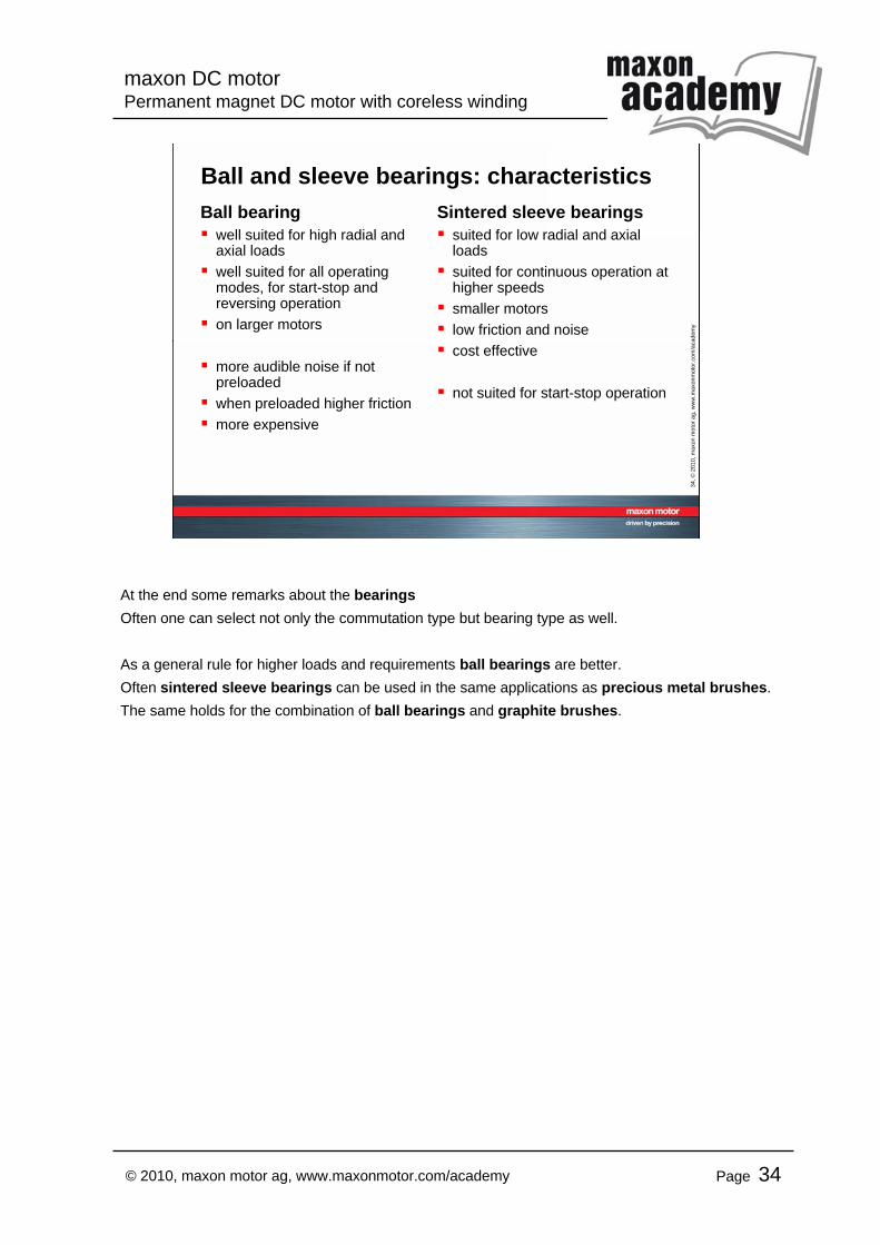
Ball and sleeve bearings: characteristicsBall bearing
well suited for high radial and axial loadswell suited for all operating modes, for start-stop and reversing operationon larger motors
more audible noise if not preloadedwhen preloaded higher frictionmore expensive
Sintered sleeve bearingssuited for low radial and axial loadssuited for continuous operation at higher speedssmaller motorslow friction and noisecost effective
not suited for start-stop operation
At the end some remarks about the bearingsOften one can select not only the commutation type but bearing type as well.
As a general rule for higher loads and requirements ball bearings are better.Often sintered sleeve bearings can be used in the same applications as precious metal brushes.The same holds for the combination of ball bearings and graphite brushes.