Embed Size (px)
Citation preview
8/16/2019 Maxsys PC4010 - Manual Utilizare.pdf
http://slidepdf.com/reader/full/maxsys-pc4010-manual-utilizarepdf 1/28
1
Table of ContentsIntroduction ........................................................................................................ 2
About Your Security System .............................................................................. 2
Fire Detection ............................................................................................... 2
Monitoring .................................................................................................... 2General System Operation .......................................................................... 3
Keypad LED Displays ....................................................................................... 3
System Master Menu Functions ........................................................................ 3
Partition Status Enunciator ................................................................................ 4
Global Keypads ................................................................................................. 4
What is a Global Keypad? ........................................................................... 4How to use a Global Keypad? ..................................................................... 4
Display of Alarms/Bypassed Zones .................................................................. 9
Auto-bypass/Home-Away Arming ..................................................................... 9
Partition Keypads ............................................................................................ 10Keypad Zones ............................................................................................ 10
Arming ........................................................................................................ 10
Disarming ................................................................................................... 12User Programming Commands []+[5]+[Access Code] ......................... 13
Programming Additional Access Codes Usinga System Master Code or a Supervisory Code ....................................... 15
Zone Bypassing []+[1] ............................................................................ 17Trouble Display []+[2] ............................................................................. 18
Alarm Memory Display []+[3] .................................................................. 21
Sensor Reset []+[4] when disarmed ....................................................... 21User Functions Command []+[6]+[Access Code] ................................. 21
Walk Test []+[6]+[Walk Test Code] when disarmed .............................. 23
Door Strike []+[7] or []+[7]+[Access Code] ........................................ 24Installer’s Programming Commands []+[8]+[Installer’s Code] .............. 24“At-Home” Arming []+[9]+[Access Code] .............................................. 24
Quick Arm []+[0] ..................................................................................... 25
Quick Exit []+[0] when armed ................................................................. 25
Keypad Lockout .............................................................................................. 25
Fire Safety in the Home ................................................................................... 25
Household Fire Safety Audit ............................................................................ 25
Family Escape Planning .................................................................................. 26
Maintenance .................................................................................................... 27
Limited Warranty .............................................................................................. 27
Appendix A
List of Available ASCII Characters ............................................................ 28
8/16/2019 Maxsys PC4010 - Manual Utilizare.pdf
http://slidepdf.com/reader/full/maxsys-pc4010-manual-utilizarepdf 2/28
2
IntroductionThe LCD4500 keypad provides easy to understand English languageinformation about the status of your security system and makes dailyoperation simple by prompting the user through each operation.
The keypad provides audible feedback each time a key is pressed and withunique audible sequences it signals troubles and the correct or incorrectentry of information.
About Your Security SystemYour DSC security equipment has been designed to give you the greatestpossible flexibility and convenience. The LCD4500 keypad will guide youthrough each operation with English language prompts. Read this manualcarefully and have your installer instruct you on system operation and on
which features have been implemented on your system. All users of thissystem should be equally instructed in its use.
FIRE DETECTION
This equipment is capable of monitoring fire detection devices such assmoke detectors and providing a warning alarm if a fire condition isdetected. Good fire detection depends on having adequate numbers of firedetectors placed in appropriate locations. This equipment should beinstalled in accordance with N.F.P.A. standard #74 (N.F.P.A. BatterymarchPark, Quincey MA 02269). Carefully review the Family Escape Planningguidelines in this manual.
Note: Your installer must enable the fire detection portion of this equipment before it becomes functional.
Important Note A security system cannot prevent emergencies. It is only intended to alert you and,if included, a monitoring station of an emergency situation. Security systems are generally very reliable but they may not work under all conditions and they are not a substitute for prudent security practices or life and property insurance. Your security system should be installed and serviced by qualified security professionals who should instruct you on the level of protection that has been provided and on system operation.
MONITORINGThis system is capable of transmitting alarms, troubles, and emergencyinformation over telephone lines to a monitoring station. If you inadvertentlyinitiate an alarm, immediately call the monitoring station to prevent anunnecessary response.
Note: The monitoring function must be enabled by the installer before it becomes functional.
8/16/2019 Maxsys PC4010 - Manual Utilizare.pdf
http://slidepdf.com/reader/full/maxsys-pc4010-manual-utilizarepdf 3/28
3
GENERAL SYSTEM OPERATIONYour security system is made up of a PC4010 and one or more LCD4500and various detectors and sensors. The DSC control panel will be mountedout of the way in a utility room or basement. The metal cabinet contains thesystem electronics, fuses and stand-by battery. There is normally no reasonfor anyone but the installer or service person to have access to the controlpanel. The LCD4500 keypads have an audible indicator, an alphanumericLCD, (Liquid Crystal Display), and command entry keys. The keypad is usedto send commands to the system and to display the current system status.The keypad(s) will be mounted in convenient locations inside the protectedpremises close to the exit-entry doors.
The security system has several zones or areas of protection and each ofthese zones will have one or more detection sensors connected to it (motiondetectors, glassbreak detectors, door contacts or shock sensors).
Keypad LED DisplaysREADY LIGHT (LCD45X1 KEYPADS ONLY)
If the Ready light is ON, the partition is ready for arming.
If the Ready light is OFF, check to see that all doors and windows areclosed and that all movement is stopped in areas covered by motiondetectors. The partition cannot be armed unless the Ready light is ONindicating that all zones are closed and the partition is in the Ready state.
ARMED LIGHT
If the Armed light is ON, the partition has been armed successfully.
TROUBLE LIGHT
If the Trouble light is ON, check to see what the trouble condition is and callfor service.
System Master Menu FunctionsSystem Master Codes may perform any function for any partition on thesystem except changing or deleting the System Grand Master Code.
The System Master Menu can be accessed by entering [System MasterCode] [9]. Use the [<] [>] keys to display the items of the System MasterMenu. Press [] to select an item:
[0] View Event Buffer [1] Set System Time [2] Set System Date[3] Enable DLS Window [4] System Reset [5] Previous Menu
[0] View Event Buffer - This function allows any Master Code to review theEvent Buffer on the keypad display. The first line of the display will showthe event number and the partition on which the event occurred; thesecond line of the display will show the date and time of the event. Pressthe [] key to display a description of the event. Use the [<] [>] keys to
scroll through the list of events in the Event Buffer.
[1] Set System Time programs the system’s 24 hour clock. Enter 4 digits in24 hour time to set the clock, the first 2 digits are the hour, the last 2digits are the minutes. For example, to program 2:35 pm, type in 1435.
8/16/2019 Maxsys PC4010 - Manual Utilizare.pdf
http://slidepdf.com/reader/full/maxsys-pc4010-manual-utilizarepdf 4/28
4
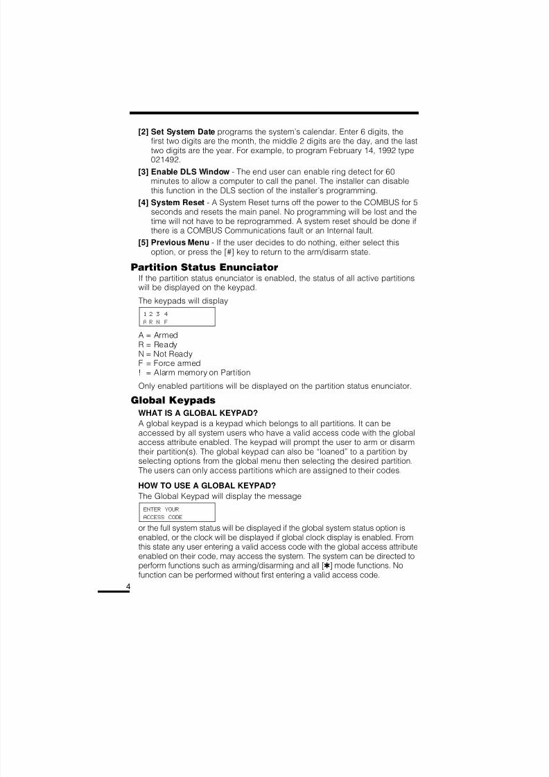
[2] Set System Date programs the system’s calendar. Enter 6 digits, thefirst two digits are the month, the middle 2 digits are the day, and the lasttwo digits are the year. For example, to program February 14, 1992 type021492.
[3] Enable DLS Window - The end user can enable ring detect for 60minutes to allow a computer to call the panel. The installer can disablethis function in the DLS section of the installer’s programming.
[4] System Reset - A System Reset turns off the power to the COMBUS for 5seconds and resets the main panel. No programming will be lost and thetime will not have to be reprogrammed. A system reset should be done ifthere is a COMBUS Communications fault or an Internal fault.
[5] Previous Menu - If the user decides to do nothing, either select thisoption, or press the [#] key to return to the arm/disarm state.
Partition Status EnunciatorIf the partition status enunciator is enabled, the status of all active partitionswill be displayed on the keypad.
The keypads will display
1 2 3 4
A R N F
A = ArmedR = ReadyN = Not ReadyF = Force armed! = Alarm memory on Partition
Only enabled partitions will be displayed on the partition status enunciator.
Global Keypads
WHAT IS A GLOBAL KEYPAD?
A global keypad is a keypad which belongs to all partitions. It can beaccessed by all system users who have a valid access code with the globalaccess attribute enabled. The keypad will prompt the user to arm or disarmtheir partition(s). The global keypad can also be “loaned” to a partition byselecting options from the global menu then selecting the desired partition.The users can only access partitions which are assigned to their codes.
HOW TO USE A GLOBAL KEYPAD?
The Global Keypad will display the message
ENTER YOUR
ACCESS CODE
or the full system status will be displayed if the global system status option isenabled, or the clock will be displayed if global clock display is enabled. From
this state any user entering a valid access code with the global access attributeenabled on their code, may access the system. The system can be directed toperform functions such as arming/disarming and all [] mode functions. Nofunction can be performed without first entering a valid access code.
8/16/2019 Maxsys PC4010 - Manual Utilizare.pdf
http://slidepdf.com/reader/full/maxsys-pc4010-manual-utilizarepdf 5/28
5
• Single Partition Access CodeENTER YOUR
ACCESS CODE
The user enters a valid single partition access code.
[*] TO VIEW < >
SYSTEM TROUBLES
This message will be displayed if there are troubles on the system and theinstaller has enabled the option “GLB KYPD TRB” in the system togglessection.
VIEW TROUBLE < >
(TROUBLE MESSAGE)
Press [] to view the troubles on the system. The user can scroll throughthe troubles by using the [<][>] keys.
(PARTITION LABEL)
[*] TO ARM < >
This message will be displayed if the partition is ready to be armed. Pressthe [] key to arm.
WARNING
BYPASS ACTIVE
This message will be displayed for 3 seconds if the partition is armed withzones bypassed.
PARTITION ARMED
WITH OPEN ZONES
This message will be displayed for 3 seconds if the partition is armed withforce armable zones open.
EXIT DELAY
IN PROGRESS...
This message will be displayed for 3 seconds when a partition is armed.
ENTER YOUR
ACCESS CODE
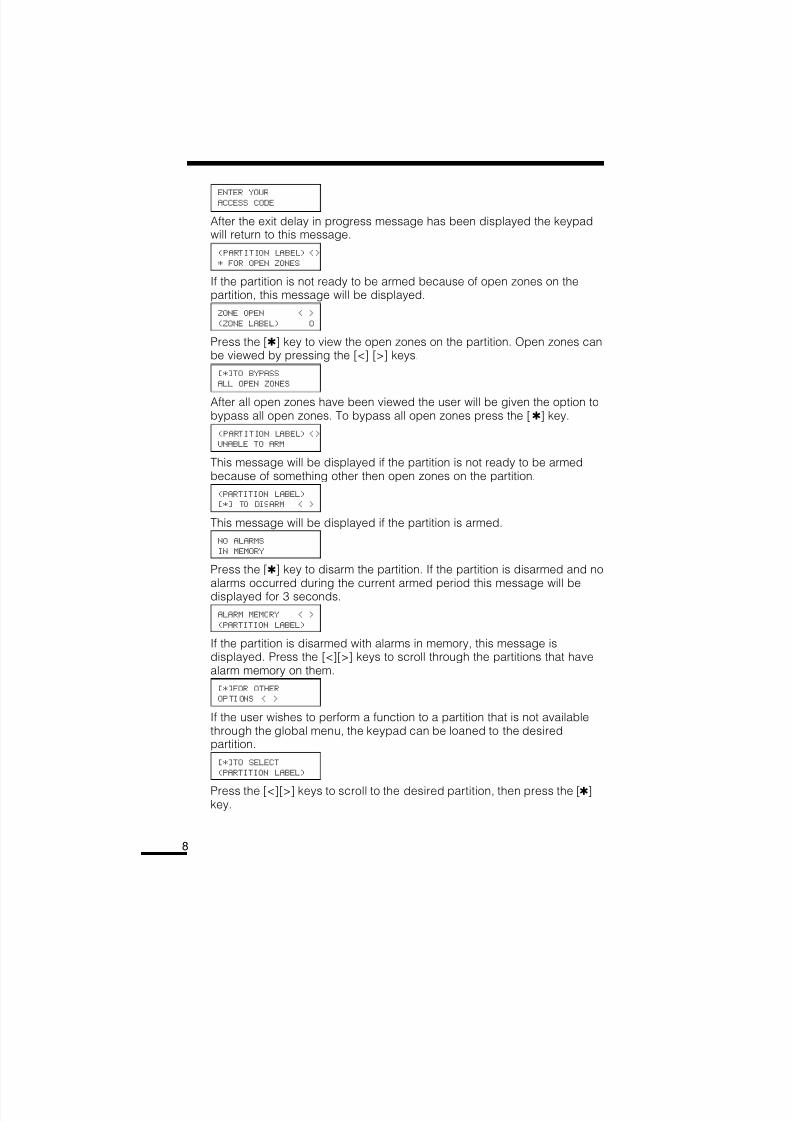
After the exit delay in progress message has been displayed the keypadwill return to this message.
(PARTITION LABEL) <>
* FOR OPEN ZONES
If the partition is not ready to be armed because of open zones on thepartition, this message will be displayed.
ZONE OPEN < >
(ZONE LABEL) O
Press the [] key to view the open zones on the partition. Open zones can
be viewed by pressing the [<] [>] keys.[*]TO BYPASS
ALL OPEN ZONES
8/16/2019 Maxsys PC4010 - Manual Utilizare.pdf
http://slidepdf.com/reader/full/maxsys-pc4010-manual-utilizarepdf 6/28
6
After all open zones have been viewed the user will be given the option tobypass all open zones. To bypass all open zones press the [] key.
(PARTITION LABEL) <>
UNABLE TO ARM
This message will be displayed if the partition is not ready to be armedbecause of something other then open zones on the partition.
(PARTITION LABEL)
[*] TO DISARM < >
This message will be displayed if the partition is armed.
NO ALARMS
IN MEMORY
Press the [] key to disarm the partition. If the partition is disarmed and noalarms occurred during the current armed period this message will be
displayed for 3 seconds.ALARM MEMORY < >
(PARTITION LABEL)
If the partition is disarmed with alarms in memory, this message isdisplayed. Press the [<][>] keys to scroll through the partitions that havealarm memory on them.
[*]FOR OTHER
OPTIONS < >
If the user wishes to perform a function to a partition that is not availablethrough the global menu, the keypad can be loaned to the desiredpartition be pressing the [] key at this option.
ACCESSING
(PARTITION LABEL)
When a keypad is loaned to another partition this message will bedisplayed for 3 seconds. Once the keypad is loaned to another partition, itwill function as if it was a keypad that belonged to that partition. The userwill be able to perform all [] functions (e.g. [] [7] Door Strike) anddisarm the panel using conventional methods.
EXITING FROM
(PARTITION LABEL)
The keypad will return to global mode after 20 seconds of no key pressesmade (this time is programmable by the installer). The keypad will alsoreturn to global mode if the [#] key is pressed. This message will bedisplayed for 3 seconds then the keypad will return to global mode.
• Multi-partition Access Code
ENTER YOUR
ACCESS CODE
The user enters a valid multi partition access code.
8/16/2019 Maxsys PC4010 - Manual Utilizare.pdf
http://slidepdf.com/reader/full/maxsys-pc4010-manual-utilizarepdf 7/28
7
[*] TO VIEW < >SYSTEM TROUBLES
This message will be displayed if there are troubles on the system and theinstaller has enabled the option “GLB KYPD TRB” in the system togglessection.
VIEW TROUBLE < >
(TROUBLE MESSAGE)
Press [] to view the troubles on the system. The user can scroll throughthe troubles by using the [<][>] keys.
[*] TO ARM < >
YOUR PARTITIONS
This message will be displayed if all partitions that the access codebelongs to are ready to be armed. Press the [] key to arm all partitionsthat the code belongs to. The panel will only arm partitions that belong tothe entered access code.
UNABLE TO ARM
YOUR PARTITIONS
This message will be displayed if any one of the partitions that the accesscode belongs to is not ready to be armed.
[*] TO DISARM < >
YOUR PARTITIONS
This message will be displayed if any of the partitions that the accesscode belongs to are armed. Press the [] key to disarm all partitions thatthe access code belongs to. The panel will only disarm partitions thatbelong to the entered access code.
(PARTITION LABEL)
[*] TO ARM < >
Press the [<][>] keys to scroll through the partitions. Note that onlypartitions that belong to the access code entered can be viewed. Thismessage will be displayed if the partition is ready to be armed. Press the[] key to arm.
WARNING
BYPASS ACTIVE
This message will be displayed for 3 seconds if the partition is armed withzones bypassed.
PARTITION ARMED
WITH OPEN ZONES
This message will be displayed for 3 seconds if the partition is armed withforce armable zones open.
EXIT DELAY
IN PROGRESS...
This message will be displayed for 3 seconds when a partition is armed.
8/16/2019 Maxsys PC4010 - Manual Utilizare.pdf
http://slidepdf.com/reader/full/maxsys-pc4010-manual-utilizarepdf 8/28
8
ENTER YOUR
ACCESS CODE
After the exit delay in progress message has been displayed the keypadwill return to this message.
(PARTITION LABEL) <>
* FOR OPEN ZONES
If the partition is not ready to be armed because of open zones on thepartition, this message will be displayed.
ZONE OPEN < >
(ZONE LABEL) O
Press the [] key to view the open zones on the partition. Open zones canbe viewed by pressing the [<] [>] keys.
[*]TO BYPASS
ALL OPEN ZONES
After all open zones have been viewed the user will be given the option tobypass all open zones. To bypass all open zones press the [] key.
(PARTITION LABEL) <>
UNABLE TO ARM
This message will be displayed if the partition is not ready to be armedbecause of something other then open zones on the partition.
(PARTITION LABEL)
[*] TO DISARM < >
This message will be displayed if the partition is armed.
NO ALARMS
IN MEMORY
Press the [] key to disarm the partition. If the partition is disarmed and no
alarms occurred during the current armed period this message will bedisplayed for 3 seconds.
ALARM MEMORY < >
(PARTITION LABEL)
If the partition is disarmed with alarms in memory, this message isdisplayed. Press the [<][>] keys to scroll through the partitions that havealarm memory on them.
[*]FOR OTHER
OPTIONS < >
If the user wishes to perform a function to a partition that is not availablethrough the global menu, the keypad can be loaned to the desiredpartition.
[*]TO SELECT
(PARTITION LABEL)
Press the [<][>] keys to scroll to the desired partition, then press the []key.
8/16/2019 Maxsys PC4010 - Manual Utilizare.pdf
http://slidepdf.com/reader/full/maxsys-pc4010-manual-utilizarepdf 9/28
9
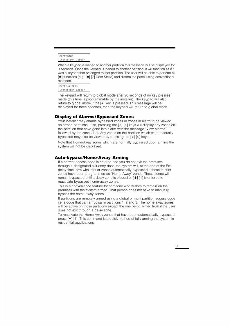
ACCESSING
(Partition label)
When a keypad is loaned to another partition this message will be displayed for3 seconds. Once the keypad is loaned to another partition, it will function as if itwas a keypad that belonged to that partition. The user will be able to perform all[] functions (e.g. [] [7] Door Strike) and disarm the panel using conventionalmethods.
EXITING FROM
(Partition Label)
The keypad will return to global mode after 20 seconds of no key pressesmade (this time is programmable by the installer). The keypad will alsoreturn to global mode if the [#] key is pressed. This message will bedisplayed for three seconds, then the keypad will return to global mode.
Display of Alarms/Bypassed ZonesYour installer may enable bypassed zones or zones in alarm to be viewedon armed partitions. If so, pressing the [<] [>] keys will display any zones onthe partition that have gone into alarm with the message “View Alarms”followed by the zone label. Any zones on the partition which were manuallybypassed may also be viewed by pressing the [<] [>] keys.
Note that Home-Away zones which are normally bypassed upon arming thesystem will not be displayed.
Auto-bypass/Home-Away ArmingIf a correct access code is entered and you do not exit the premisesthrough a designated exit-entry door, the system will, at the end of the Exit
delay time, arm with interior zones automatically bypassed if those interiorzones have been programmed as “Home-Away” zones. These zones willremain bypassed until a delay zone is tripped or [] [1] is entered toreactivate bypassed home-away zones.
This is a convenience feature for someone who wishes to remain on thepremises with the system armed. That person does not have to manuallybypass the home-away zones.
If partitions are remotely armed using a global or multi partition access codei.e. a code that can arm/disarm partitions 1, 2 and 3. The home-away zoneswill be active on those partitions except the one being armed from if the userdoes not exit through a delay zone.
To reactivate the Home-Away zones that have been automatically bypassed,press [] [1]. This command is a quick method of fully arming the system inresidential applications.
8/16/2019 Maxsys PC4010 - Manual Utilizare.pdf
http://slidepdf.com/reader/full/maxsys-pc4010-manual-utilizarepdf 10/28
10
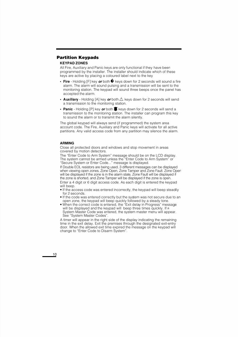
Partition KeypadsKEYPAD ZONES
All Fire, Auxiliary and Panic keys are only functional if they have beenprogrammed by the installer. The installer should indicate which of thesekeys are active by placing a coloured label next to the key.
• Fire - Holding [F] key or both keys down for 2 seconds will sound a firealarm. The alarm will sound pulsing and a transmission will be sent to themonitoring station. The keypad will sound three beeps once the panel hasaccepted the alarm.
• Auxiliary - Holding [A] key or both keys down for 2 seconds will senda transmission to the monitoring station.
• Panic - Holding [P] key or both keys down for 2 seconds will send atransmission to the monitoring station. The installer can program this key
to sound the alarm or to transmit the alarm silently.The global keypad will always send (if programmed) the system areaaccount code. The Fire, Auxiliary and Panic keys will activate for all activepartitions. Any valid access code from any partition may silence the alarm.
ARMING
Close all protected doors and windows and stop movement in areascovered by motion detectors.
The “Enter Code to Arm System” message should be on the LCD display.The system cannot be armed unless the “Enter Code to Arm System” or“Secure System or Enter Code...” message is displayed.
If Double EOL resistors are being used, 3 different messages can be displayedwhen viewing open zones, Zone Open, Zone Tamper and Zone Fault. Zone Openwill be displayed if the zone is in the alarm state, Zone Fault will be displayed if
the zone is shorted, and Zone Tamper will be displayed if the zone is open.Enter a 4 digit or 6 digit access code. As each digit is entered the keypadwill beep.• If the access code was entered incorrectly, the keypad will beep steadily
for 2 seconds.• If the code was entered correctly but the system was not secure due to an
open zone, the keypad will beep quickly followed by a steady tone.• When the correct code is entered, the “Exit delay in Progress” message
will be displayed and the keypad will beep three times quickly. If aSystem Master Code was entered, the system master menu will appear.See “System Master Codes”.
A timer will appear in the right side of the display indicating the remainingtime in the exit delay. Exit the premises through the designated exit-entrydoor. When the allowed exit time expired the message on the keypad willchange to “Enter Code to Disarm System”.
8/16/2019 Maxsys PC4010 - Manual Utilizare.pdf
http://slidepdf.com/reader/full/maxsys-pc4010-manual-utilizarepdf 11/28
11
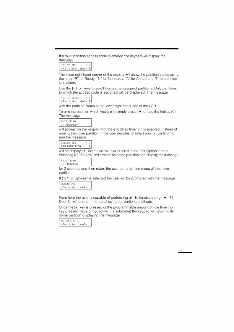
If a multi partition access code is entered the keypad will display themessage
(0) TO ARM < >
(Partition Label) R .
The lower right hand corner of the display will show the partition status usingthe letter “R” for Ready, “N” for Not ready, “A” for Armed and “!” for partitionis in alarm.
Use the [<] [>] keys to scroll though the assigned partitions. Only partitionsto which the access code is assigned will be displayed. The message
(2) TO SELECT < >
(Partition Label) R
with the partition status at the lower right hand side of the LCD.
To arm the partition which you are in simply press [] or use the hotkey (0).
The messageEXIT DELAY
IN PROGRESS
will appear on the keypad with the exit delay timer if it is enabled. Instead ofarming their own partition, if the user decides to select another partition toarm the message
SELECT (0) < >
ARM PARTITION R
will be displayed. Use the arrow keys to scroll to the “For Options” menu.Selecting (0) “To Arm” will arm the selected partition and display the message
EXIT DELAY
IN PROGRESS
for 2 seconds and then return the user to the arming menu of their ownpartition.
If (1) “For Options” is selected the user will be prompted with the message
ACCESSING
(Partition Label) .
From here the user is capable of performing all [] functions (e.g. [] [7]Door Strike) and arm the panel using conventional methods.
Once the [#] key is pressed or the programmable amount of idle time (nokey presses made or not active in a submenu) the keypad will return to itshome partition displaying the message
RETURNING TO
(Partition Label) .
8/16/2019 Maxsys PC4010 - Manual Utilizare.pdf
http://slidepdf.com/reader/full/maxsys-pc4010-manual-utilizarepdf 12/28
12
DISARMINGEnter the premises through the designated exit-entry door. The keypad
buzzer will be on. Go to the keypad and enter the 4 digit or 6 digitaccess code. If an error is made in entering the code, press the [#] key
and enter the code again. The “Armed” light will go out and the keypadbuzzer will stop. The correct access code must be entered before the
allowed entry time expires. To change the entry time see “InstallersProgramming Command”, [][8]. If an alarm occurred while the panel
was armed, the “View Memory” message will be on the display with the
zone label for the zone that caused the alarm. The display will keepthose messages on for two minutes or until the [#] key is pressed to
return the panel to the normal arm-disarm mode.
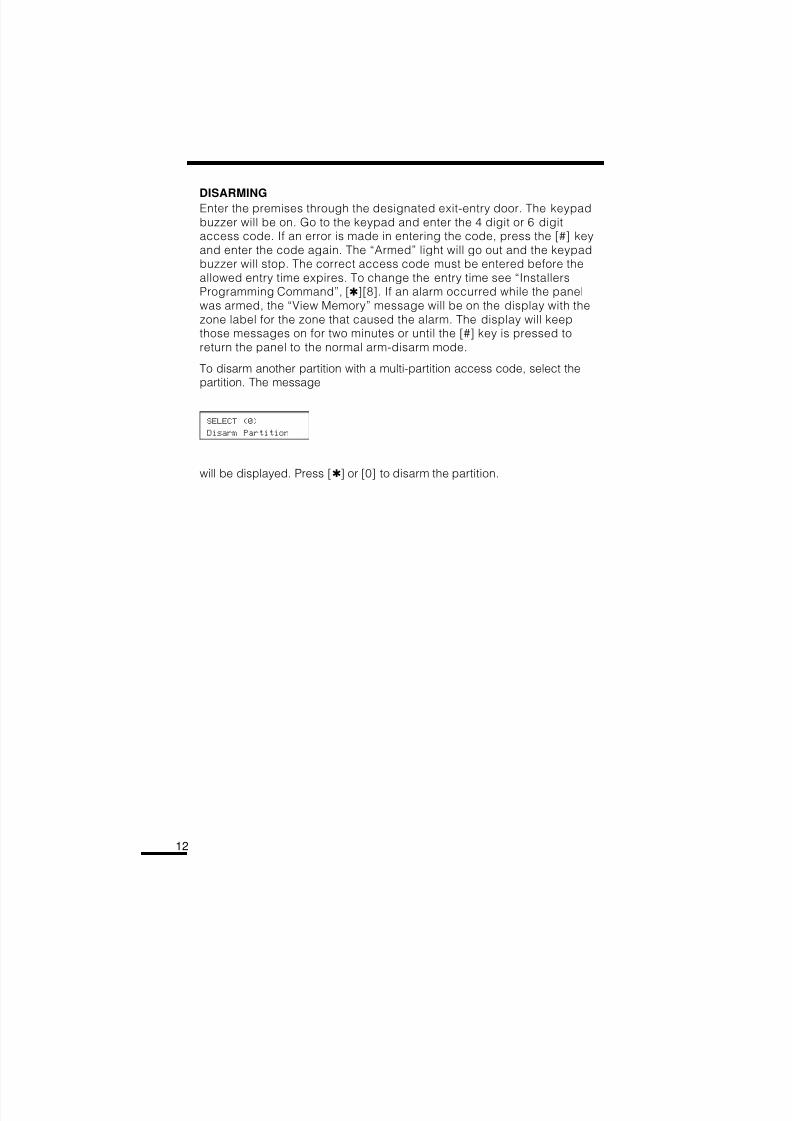
To disarm another partition with a multi-partition access code, select thepartition. The message
SELECT (0)
Disarm Partition
will be displayed. Press [] or [0] to disarm the partition.
8/16/2019 Maxsys PC4010 - Manual Utilizare.pdf
http://slidepdf.com/reader/full/maxsys-pc4010-manual-utilizarepdf 13/28
13
USER PROGRAMMING COMMANDS[]+[5]+[ACCESS CODE]
The [] [5] [Access Code] command is used to program the Master Codesand regular access codes.
The first access code is the System Grand Master Code. Normally, only theinstaller can change the System Grand Master Code. The installer may alsoprogram the system to allow the user to change the System Grand Master Code.
The System Grand Master Code has no limitations to its use. It may be usedto create or delete other System Master Codes or to perform any userfunction on the system. Note that only to the first access code can be theSystem Grand Master Code.
Note: When using a global keypad the System Master should assign access codes to avoid duplication.
Each access code may be programmed as one or a combination of thefollowing options:
• System Master Codes may perform any function for any partition on thesystem except change or delete the System Grand Master Code, orchange or delete other System Master Codes.
• Supervisory Codes allow the user to program and edit other accesscodes, except System Master and Duress Codes, for any partitions whichthe access codes belong to. Supervisory Codes are also used for arming,disarming, bypassing and all other functions that a System Master Code iscapable of.
• Arm Only Code allows the user to arm only the partitions to which thecode is assigned.
• Disarm Only Code allows the user to disarm only the partitions to whichthe code is assigned.
• Door Strike Code allows the user to operate door strikes only within thepartition to which the code is assigned. (The PC4010 has not beeninvestigated to the requirements of UL294.)
• Duress Codes are used to disarm partitions and send a duress codetransmission to the monitoring station. A user would enter a Duress Code toindicate that they are being forced by an intruder to disarm the system.When a Duress Code is entered, the partition or partitions to which it isassigned will disarm normally, and a Duress Code transmission will be sentto the monitoring station. Also, any outputs programmed as “DuressOutputs” will be activated when the Duress Code is entered. A Duress Code
may be programmed for arming and disarming; note that the “Duress Code”will be transmitted to the monitoring station for any event it performs.
8/16/2019 Maxsys PC4010 - Manual Utilizare.pdf
http://slidepdf.com/reader/full/maxsys-pc4010-manual-utilizarepdf 14/28
14
• One-Time Use Codes are used to allow infrequent users of the system,such as service personnel, to arm the system. When the system is armedusing a One-Time Use Code, the code will be erased once the Exit Delayexpires; after this time, the code may not be used again. If the One-TimeUse Code is entered before the Exit Delay expires, arming of the systemwill be cancelled; the One -Time Use Code may then be entered againlater to arm the system.
• Log Only Codes are used strictly for logging to the event buffer. Thesystem master can log the time, date and location which they were at withthe Log Only codes. To enable this code type, enable just door strike ordisable all options.Note: Do not program access codes such as 1111 or 1234 which can be easily guessed and will compromise the security of your system.
• Escort 4580 Access allows the user to access the Escort 4580 (VoicePrompting Module) via the in house telephone or remotely through atelephone. The user will have the same abilities through the VPM-2 as theywould through a regular keypad.Note: Do not program One-Time Use Codes without arming or disarmingenabled.
• Global Access allows the access code to be used on global keypads.Disabling this toggle option for any access code will inhibit the code frombeing used on any global keypad.
• Partition Selection Menu brings up the partition selection menu when amulti-partition access code is entered on a partition keypad. When thisoption is disabled, multi-partition access codes will function as a singlepartition access code for the partitions the access code is enabled on.
8/16/2019 Maxsys PC4010 - Manual Utilizare.pdf
http://slidepdf.com/reader/full/maxsys-pc4010-manual-utilizarepdf 15/28
15
PROGRAMMING ADDITIONAL ACCESS CODES USING A SYSTEMMASTER CODE OR A SUPERVISORY CODE
1 Press [] then [5] to enter the User Programming Commands; thekeypad will display the message “Enter Your Access Code”. Any SystemMaster Code or Program Code may be entered.
• If the Grand Master Code is entered, System Master Codes andregular access codes for any partition will be able to be programmed.
• If a System Master Code is entered, regular access codes for anypartition will be able to be programmed. A System Master Code canalso create Supervisory and Duress Codes.
• If a Supervisory Code is entered, only access codes belonging to thepartition to which the Supervisory Code is assigned may be changed.
When a valid access code is entered, the keypad will display the number
of available access codes on the first line of the screen.
2 The keypad will display the message “Sel Code (xxx) < >”. “(xxx)”represents the number of the access code that has been selected forprogramming and the access code name on the second line. Use the [<][>] keys to scroll through the list of access codes, or enter the codenumber 001 to 128. When the desired access code number is displayed,press the [] key to program the code.
3 When an access code is selected for editing by pressing the [] key, amenu for editing access codes will be displayed. Select one of the menuitems by entering a number on the keypad.
[0] Program Code - When [0] is pressed, the keypad will display the
message “Enter Digits” and the presently-programmed access code.Enter the new 4 digit or 6 digit access code. Do not press [] or [#]while entering the access code. If you do not wish to change thecode, press [#] key.
[1] Erase Code - If an access code is no longer needed, this selectionwill erase the code, but not the user’s name.
[2] Edit Access Code Name - When a PC4400 RS232 module is enrolledon the system, the name of the code which is used to arm and disarmwill be printed out. Also, the access code name helps keep track of thecode when programming codes. Move the cursor to left or right bypressing the [<][>] keys. The letters of the alphabet have been dividedup among the 1 to 9 number keys on the keypad as below:
[1] = A, B, C, 1 [2] = D, E, F, 2 [3] = G, H, I, 3
[4] = J, K, L, 4 [5] = M, N, O, 5 [6] = P, Q, R, 6
[7] = S, T, U, 7 [8] = V, W, X, 8 [9] = Y, Z, 9, 0
[0] = Space
8/16/2019 Maxsys PC4010 - Manual Utilizare.pdf
http://slidepdf.com/reader/full/maxsys-pc4010-manual-utilizarepdf 16/28
16
For example, if you press the [4] key once, the letter ‘J’ will appearabove the cursor on the display. Press the [4] key again, the nextletter ‘K’ will appear, and so on. If a different number key is pressed,e.g. the [6] key, the cursor will automatically move to the right onespace, i.e. the letter ‘P’. To erase a character, use the [<] [>] keys tomove the cursor under the character, then press the [0] key.
While programming the access code label, press the [] key to callup an options menu. To select an option, press the correspondingnumber key or scroll through the options using the [<][>] keys, thenpress the [] key to select.
[0] Clear Display will clear the entire code label.
[1] Clear to End will clear the display from the character where thecursor was located to the end of the display.
[2] Change Case will toggle the letter entry between upper case letters
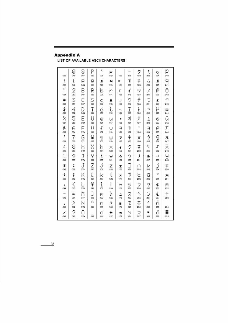
(ABC...) and lower case letters (abc...).[3] ASCII Entry (see Appendix A) is for entering uncommon characters.There are 255 characters, but 000 to 031 are not used. Use the [<][>]keys to toggle through the characters or enter a 3 digit number from 032to 255. Press the [] key to enter the character into the code label.
[3] Edit Access Code Options - When [3] is pressed, the keypad willdisplay the message “Select toggle < >”. Use the [<] [>] keys toscroll through the list of options:• System Master? • Bypass? • 4580 Access?• Program Codes? • Door Strike? • Global Access?• Arm? • Duress Pulse? • Partition Selection• Disarm? • One Time Use? Menu?
[4] Edit Partition Mask - The Partition Mask is used to assign the accesscode to one or more partitions. In order for an access code tofunction, the Partition Mask must be assigned to the access code; if no partition mask is assigned, the code will not operate on any partition.
[5] To Exit the menu, press the [#] key.
4 To exit the Access Code Programming Mode, press [#].
8/16/2019 Maxsys PC4010 - Manual Utilizare.pdf
http://slidepdf.com/reader/full/maxsys-pc4010-manual-utilizarepdf 17/28
17
ZONE BYPASSING[]+[1]
A bypassed zone will not cause an alarm. If a zone is bypassed the panelmay be armed even if the zone is open. Use zone bypassing when accessis needed to part of the protected area. Also, damaged wiring or contactson a zone may be temporarily bypassed until repairs can be made so thatthe panel can be armed.
To bypass zones, enter [] [1]. An access code may be required if theinstaller has enabled that option. A menu will appear.
[0] Bypass Zones - This selection takes you immediately to bypassingzones. Use the [<] [>] to select the zones to be bypassed and press the []key to select the zone. A “” will appear beside the zone label to indicatethe zone will be bypassed when the partition is armed.
A zone search routine allows the user to find the desired zone to bypass by
entering in the first letter of the zone to search for, and pressing one of the[<][>] keys. The [>] key will search for the first zone on the partition thatbegins with the letter selected. Pressing the [>] key again will search for thenext zone on the partition that begins with the letter selected.
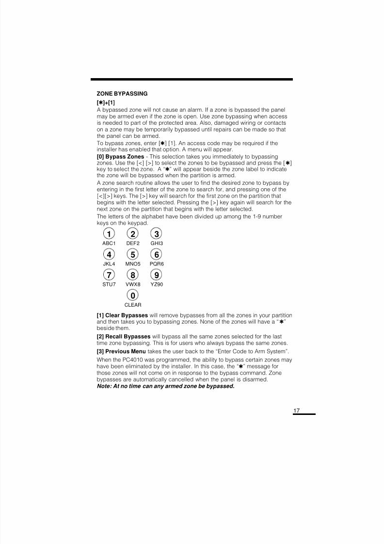
The letters of the alphabet have been divided up among the 1-9 numberkeys on the keypad.
1 2 3ABC1 DEF2 GHI3
4 5 6JKL4 MNO5 PQR6
7 8 9
STU7 VWX8 YZ90
0CLEAR
[1] Clear Bypasses will remove bypasses from all the zones in your partitionand then takes you to bypassing zones. None of the zones will have a “”beside them.
[2] Recall Bypasses will bypass all the same zones selected for the lasttime zone bypassing. This is for users who always bypass the same zones.
[3] Previous Menu takes the user back to the “Enter Code to Arm System”.
When the PC4010 was programmed, the ability to bypass certain zones mayhave been eliminated by the installer. In this case, the “” message forthose zones will not come on in response to the bypass command. Zone
bypasses are automatically cancelled when the panel is disarmed.Note: At no time can any armed zone be bypassed.
8/16/2019 Maxsys PC4010 - Manual Utilizare.pdf
http://slidepdf.com/reader/full/maxsys-pc4010-manual-utilizarepdf 18/28
18
While the system is disarmed, bypassing can be used to temporarily silencethe door chime feature on a zone. Simply bypass the zone that the doorchime feature enabled. The keypad will no longer beep when the zone isopened. Be sure to clear all bypasses before arming, to ensure no zonesare unintentionally bypassed.
TROUBLE DISPLAY
[]+[2]
The PC4010 continuously monitors a number of possible trouble conditions.If one of these conditions occurs, the keypad “TROUBLE” indicator will lightand the audible indication will sound (two short beeps every 10 seconds).When the [#] key is pressed the audible indication will stop on that partition,but the trouble indicator light will remain ON until the trouble is cleared.Trouble conditions can also be transmitted to the monitoring station. Pressthe [] then [2] keys to display the trouble conditions.
• Battery Trouble
• AC Trouble
• Aux Supply Troub
• TLM Trouble
• TLM TBL Line #1
• TLM TBL Line #2
• FTC Trouble
• Bell CCT Trouble
• Fire Trouble
• Fire Trouble 2WS
• Loss of Time
• Module Com Fault
• COMBUS Low Pwr
• Internal Fault
• 4204 Battery TBL
• 4204 AC Trouble
• 4204 Aux Trouble
• Ground Fault
• Waterflow TBL
• Cellular Trouble
• DLS Fault TBL
• Zn Sensor Fault
• Zn LwBatt Fault
• X10 Fault
• Printer Off-Line
• PC4400 Trouble
Press [#] to return to “READY”.
Battery Trouble - A battery trouble will be displayed and can be reported ifthe battery is 11.3 volts or less, disconnected or the battery fuse fails. Batteryvoltage is checked once every 4 minutes, so the battery trouble may notrestore instantly when the battery is restored. Initiating a bell/comm test willcheck the battery voltage. When DC Inhibit Arm is enabled the panel willcheck the condition of the batteries on the system (main panel and PC4204)when an access code is entered. If during this check the battery shows alow voltage condition the arming will be inhibited. The LCD will display themessage "Fail To Arm... Battery Trouble" when this occurs.
The Control panel and each of the PC4204 modules may only have 3 batterytrouble alarms in a 24 hour period. After the third battery trouble for a givenmodule the trouble condition will "Shutdown" until midnight of that day. Thetrouble will still be enunciated with the keypad Trouble LED but the event willnot be logged to the event buffer or be communicated.
AC Trouble - There is no audible annunciation on AC power failure. Thesystem “Trouble” light will come ON but the audible indication will not sounduntil there is a low battery condition. Transmission delay can beprogrammed for 000 to 255 minutes.
8/16/2019 Maxsys PC4010 - Manual Utilizare.pdf
http://slidepdf.com/reader/full/maxsys-pc4010-manual-utilizarepdf 19/28
19
Aux Supply Troub - An Aux trouble is generated if the aux fuse on the mainpanel opens, or if the Aux or SW Aux terminals are overloaded.
TLM Trouble - A telephone line trouble is generated when the line voltagedrops below 3 volts for more than 30 seconds. A keypad trouble isgenerated when the system is disarmed and if selected, a local alarmsounds when the panel is armed.
TLM TBL Line #1 - When using the PC4700 Fire Module a telephone line troubleis generated when the line voltage drops below 3 volts for more than 30 secondson line one. A keypad trouble is generated when the system is disarmed and ifselected, a local alarm sounds when the panel is armed.
TLM TBL Line #2 - When using the PC4700 Fire Module a telephone linetrouble is generated when the line voltage drops below 3 volts for more than30 seconds on line two. A keypad trouble is generated when the system is
disarmed and if selected, a local alarm sounds when the panel is armed.FTC Trouble - If the digital communicator is unsuccessful in communicating withthe monitoring station after 10 attempts, a Fail to Communicate trouble isgenerated. If a later attempt to communicate is successful the trouble is cleared.
Bell CCT Trouble - If the bell fuse opens or the bell circuit is open, akeypad trouble and a Bell Circuit trouble transmission are generated.
Fire Trouble - If a FIRE loop is open circuit, a keypad trouble and a FireLoop trouble transmission are generated. A trouble on the FIRE loop willunconditionally initiate an audible and visual (trouble light) indication on thekeypad. This means that even if any other previous trouble has beensilenced, a FIRE loop trouble will restart the keypad buzzer.
Fire Trouble 2WS - If the fire zone on a PC4700 Fire Module is opened, avisual keypad trouble (trouble LED will come on) with audible indication and
a fire zone trouble transmission is generated. The LCD will show themessage "FIRE TROUBLE!! 2 Wire Smoke", until the fire zone trouble isrestored. If there is more than one PC4700 trouble condition present thesetrouble messages will scroll every 3 seconds to the next message.
Loss of Time - When the PC4010 is powered up, the internal time of dayclock needs to be set to the correct time. This trouble is cleared when anattempt is made to reset the internal time of day clock. See “System MasterCodes” for resetting the time of day clock.
Module Com Fault - The panel has lost communications with a module andcannot recover it. Check to see if the module is connected properly, then doa system reset. See “Diagnostics” in the Programming Manual to determinewhich module is not communicating.
8/16/2019 Maxsys PC4010 - Manual Utilizare.pdf
http://slidepdf.com/reader/full/maxsys-pc4010-manual-utilizarepdf 20/28
20
COMBUS Low Pwr - Modules are not getting enough voltage from theCOMBUS. Check for proper connection of COMBUS, or the COMBUS needsto be repowered. See 4204 modules and the 4204 PGM COMBUS poweroption for supplying voltage to the COMBUS. See “Diagnostics” in theProgramming Manual to determine which module has low voltage.
Internal Fault - A problem has occurred with the COMBUS microprocessors. Ifthis trouble occurs, check connections to the COMBUS and do a system reset.
4204 Battery TBL - If any PC4204 relay output module’s battery dropsbelow 11.3 volts, a battery trouble is generated.To determine which of the PC4204’s has the low battery, check the reportingcode transmitted to the monitoring station or check the event buffer printoutif there is a printer attached, or through downloading. The battery voltage ischecked once every 4 minutes. So the battery trouble may not restoreinstantly when the battery voltage is restored.
4204 AC Trouble - If any PC4204 relay output module loses incoming AC power,the keypad trouble light will indicate a 4204 AC trouble. But there will be noaudible annunciation until there is also a low battery condition.The PC4204 AC troubles will be transmitted to the monitoring station immediately.
4204 AUX Trouble - If the Aux fuse on any PC4204 relay module shouldopen or if the Aux supply is overloaded, a 4204 Aux trouble is generated.
Ground Fault - A Ground Fault trouble condition will occur if the Earth Ground(EGND) connection is shorted to a positive voltage source or shorted to anon-earth ground potential. This trouble will generate an audible and visualtrouble as well as a Ground Fault reporting code transmission.
Waterflow TBL - If the Waterflow zone on a PC4700 Fire Module is opened(WFA or WFB), a visual keypad trouble (trouble LED will come on) with
audible indication and a Waterflow trouble transmission is generated. TheLCD will show the message "FIRE TROUBLE!! Waterflow TBL", until theWaterflow zone trouble is restored. If there is more than one PC4700 troublecondition present these trouble messages will scroll every 3 seconds to thenext message.
Cellular Trouble - This indicates that the LINKS unit has one or more of thefollowing trouble conditions: AC, battery, loss of cellular or a tamper fault.
DLS Fault TBL - This trouble condition will generate an audible and visualtrouble when the control panel fails to complete communications with thedownloading computer.
Zn Sensor Fault - This trouble condition will occur when a wireless zonefails to report a zone supervisory. To view which zone has the trouble pressthe [] key while viewing the trouble condition. The zone(s) with the trouble
condition will be displayed in numerical order on the display. A keypadtrouble is generated when the system is disarmed and a visual "Zn SensorFault" trouble and trouble reporting code will be transmitted.
8/16/2019 Maxsys PC4010 - Manual Utilizare.pdf
http://slidepdf.com/reader/full/maxsys-pc4010-manual-utilizarepdf 21/28
21
Zn LwBatt Fault - This trouble condition will occur when a wireless zonehas a low battery condition. To view which zone has the trouble press the[] key while viewing the trouble condition. The zone(s) with the troublecondition will be displayed in numerical order on the display. A keypadtrouble is generated when the system is disarmed and a visual "Zn Low BattFault" trouble and trouble reporting code will be transmitted.
Automation Fault - This trouble condition will occur well the Escort 4580 lossescommunication with the Automation Output control module. An audible trouble(VIA keypad buzzer) will be generated as well as the trouble LED activating forthe keypads. An Automation Fault trouble reporting code will be sent to themonitoring station if programmed. If there is an AC trouble present at the timethe panel will not transmit the Automation Fault reporting code.
Printer Off-Line - This trouble condition will occur if the serial printerconnected to the PC4400 serial interface module goes off-line.
PC4400 Trouble - This trouble will be displayed when a DVAC Fault occurs(The DVAC line from central station is not present), or a Module Fault occurs(The PC4400 module has failed an internal diagnostics), or if DVACcommunications has been shut down by central.
ALARM MEMORY DISPLAY
[]+[3]Press [] then [3] to enter the alarm memory mode. Any alarm caused duringthe last armed period will be displayed. The “Alarm Memory” message willonly be displayed when an alarm occurred during the last armed period.
Press [#] to return to “Ready”.
Note: Tamper alarms will not be shown in alarm memory display.
SENSOR RESET
[]+[4] When Disarmed
Entering [] [4] [access code] will reset smoke detectors assigned to thatpartition. The message “Sensor Reset In Progress...” will be displayed,along with a countdown in the lower right corner. Your installer may programthe sensor reset option so that an access code is required.
USER FUNCTIONS COMMAND
[]+[6]+[ACCESS CODE]
Enter [][6][Access Code] and then use the [<][>] keys to display the itemsof the function menu. Press [] to select an item.
[0] Quick Arm [1] Quick Exit [2]Auto Arm Control
[3]Keypad Setup [4]Bell/Comm Test [5]Door Chime[6]Spec. Messages [7]User Call Up
8/16/2019 Maxsys PC4010 - Manual Utilizare.pdf
http://slidepdf.com/reader/full/maxsys-pc4010-manual-utilizarepdf 22/28
22
Items [0], [1], [5] and [6] turn on and off various functions. To enable ordisable these functions, press the [] key to toggle “Y ”or “N” on the keypad.
Y - The function is enabledN - The function is disabled
[0] Quick Arm feature is enabled by toggling to “Y” on the keypad. Whenenabled the panel can be armed by entering [] [0].
[1] Quick Exit function is enabled by toggling to “Y” on the keypad. Whenenabled the user can exit through any delay zone without altering thestatus of the system, by entering [] [0] on the keypad.
[2] Auto Arm Control - The PC4010 can be programmed to arm a partitionat the same time each day, by enabling the auto arm function andprogramming the auto-arm time.
At the selected auto arm time, the system will give a pre-alert. Thekeypad begins to sound and the Bell/Siren will pulse once every 10
seconds to alert anyone on the premises that the system is about to arm.The bell/ siren pulse can be programmed by the installer to be silent.
The keypad will sound for 1 minute before auto arming unless the auto-arm is aborted. To abort the auto arm and silence the keypad press anykey during the pre-alert. The auto arm will be attempted at the same timethe following day. The PC4010 can be programmed by the installer torequire a code to be entered for aborting the auto arm.
Upon selecting the auto arm control function, the auto arm control menuwill appear on the LCD keypad:
[0] Auto Arm toggles “Y” or “N” to enable or disable the Auto Arm/AutoDisarm function.
[1] Schedule Arm when this toggle option is enabled the partition willfollow the Auto Arm schedule programmed (by the installer) for thatpartition. When this option is enabled the partition will not follow the Auto
Time (programmed in section 2). For the Auto Arm Time to function thisoption must be disabled.
[2] Auto Arm Time is the time the partition will automatically arm itselfevery day.
[3] Sched. Disarm when this toggle option is enabled the partition willfollow the Autodisarm schedule programmed (by the installer) for thatpartition.
Note : The auto arm time is a 24 hour clock and times must be entered as two digit numbers.
E.g. HH - 00, 01,.....10, 11,.....22, 23MM - 00, 01,.....35, 36,.....58, 59
Enter 4 digits representing the time in hours and minutes (HH:MM) basedon 24 hour or military time. Always enter a leading zero where only one
digit is required, 8:05 am would be entered as 0805, 1:30 pm would beentered as 1330.
Note: The panel will not autoarm, schedule arm, or schedule disarm,if there is a loss of time trouble present on the system.
8/16/2019 Maxsys PC4010 - Manual Utilizare.pdf
http://slidepdf.com/reader/full/maxsys-pc4010-manual-utilizarepdf 23/28
23
[3] Keypad Setup allows the user to adjust the backlighting and contrast ofthe LCD4500 keypad. When this function is selected, the keypad setupmenu will appear on the keypad:
• Bright Control adjusts the level of back lighting on the LCD displayand the backlighting on the keys.
• Contrast Control adjusts the contrast of the lettering on the LCDdisplay.
Use the [<][>] keys to toggle through the 8 different settings, and press[] to select the level of preference.
[4] Bell/Comm Test allows the end user to test the system. This optionactivates the bells for 2 seconds and sends a test code transmission tothe monitoring station.
[5] Door Chime feature is enabled or disabled by pressing the [] key totoggle from “N” to “Y” or “Y” to “N”. When the chime zone is activated,
the keypad will beep quickly 5 times. The “Beeping” on doors can beeliminated temporarily by using zone bypass, only when the panel isdisarmed.
[6] Special Messages function enables 2 special event messages to bedisplayed when one of the special events occurs.
The first message is “Fail to Arm”. It will be displayed if the user isunable to arm the partition after entering a valid code, e.g. because ofactivity on the zones.
The second message is “Alarm When Armed”. It will be displayed if analarm occurred during the previous armed period.
[7] User Call Up function must be enabled by the installer. The panel willcall the downloading computer when selected. The downloadingcomputer must be waiting for the panel to call before downloading canbe performed.
WALK TEST
[]+[6]+[Walk Test Code] When DisarmedThe Walk Test feature allows the user to test if the detectors on a partitionare in proper working order. There are 4 options in the walk test menu. Press[] to view and select the option.
[0] Local, No Bell [2] Local+Comm. Test
[1] Local Walk Test [3] Disable Walk Test
[0] Local, No Bell will not sound the bell when a zone is tripped and notransmission will take place for the zone alarm. The zone alarms will belogged to the event buffer and displayed in alarm memory.
8/16/2019 Maxsys PC4010 - Manual Utilizare.pdf
http://slidepdf.com/reader/full/maxsys-pc4010-manual-utilizarepdf 24/28
8/16/2019 Maxsys PC4010 - Manual Utilizare.pdf
http://slidepdf.com/reader/full/maxsys-pc4010-manual-utilizarepdf 25/28
25
QUICK ARM[]+[0]
Entering [] [0] is accepted as a valid arming code when the “Quick Arm”feature is activated. This command is often used when individuals are requiredto arm the system but not disarm it. This could be used with home visitors in thecase of a residential alarm or junior employees and maintenance staff in thecase of a commercial alarm. See instructions in the “[] [6] Users ProgrammingCommands” section for activating the “Quick Arm” feature. The One-Time UseCode users should not use this feature, because the One-Time Use Code willonly be erased when it is used to arm the system.
QUICK EXIT
[]+[0] WHEN ARMED
Entering [] [0] when the system is fully armed will allow the user 2 minutes
to exit the premises through any delay zone without altering the status of thesystem if the “Quick Exit” feature is enabled. After [] [0] is entered into anarmed system, one and only one delay loop may be tripped. Any additionalactivity on any other active loop will cause that loop to begin its alarmsequence. Quick exit activation will be logged onto the event buffer.
Keypad LockoutIf this feature is enabled on a partition and a programmable number of incorrectaccess codes are entered, the message “Keypad Lockout Is Active...” will bedisplayed on all partition keypads. The keypad will respond with an error tone toall further keypresses for a programmable amount of time.
Fire Safety in the Home
Most fires occur in the home and to minimize this danger it is recommendedthat a household fire safety audit be conducted and a family escape plan bedeveloped.
Household Fire Safety Audit1. Are all electrical appliances and outlets in a safe condition e.g. frayed
cords, over-loaded lighting circuits? If you are uncertain about thecondition of your electrical appliances or household service, have aprofessional evaluation.
2. Are all flammable liquids stored safely in closed containers in a wellventilated cool area? Cleaning with flammable liquids should be avoided.
3. Are fire hazardous materials (matches) well out of reach of children?
4. Are furnaces and wood burning appliances properly installed, clean and
in good working order? Have a professional evaluation.
8/16/2019 Maxsys PC4010 - Manual Utilizare.pdf
http://slidepdf.com/reader/full/maxsys-pc4010-manual-utilizarepdf 26/28
26
Family Escape PlanningThere is often very little time between the detection of a fire and the time itbecomes deadly. It is thus very important that a family escape plan bedeveloped and rehearsed.
1.Every family member should participate in developing the escape plan.
2.Study the possible escape routes from each location within the house andsince many fires occur at night, special attention should be given to theescape routes from sleeping quarters.
3.It is essential that escape from a bedroom be possible without openingthe interior door. To facilitate such an escape:
• Make sure that doors and/or windows that open to the outside are easilyopened, e.g. not painted shut.
• Simply making the exit may be too difficult for children, the elderly orhandicapped, plans for rescue should be developed. This includesmaking sure that those who are to perform the rescue can promptly hear
the fire warning signal.• If the exit means is above the ground level, an approved fire ladder or
rope should be provided as well as training in its use.
• Exits on the ground level should be kept clear, e.g. remove snow fromexterior patio doors.
• The family should have a predetermined assembly point whereeveryone can be accounted for, e.g. across the street or at a neighbour.
• Once everyone is out of the house call the Fire Department.
• A good plan emphasizes quick escape. Do not investigate first orattempt to fight the fire and do not attempt to rescue valuables or petsas this takes up valuable time. Once outside, do not re-enter the house.Wait for the fire department.
• Write the plan down and rehearse frequently so that should anemergency arise, everyone will know what they are to do. Revise theplan as conditions change, e.g. more or fewer family member orchanges to the house.
• Make sure your fire warning system is operational by conducting weeklytests as noted elsewhere in this manual. If you are unsure about systemoperation, contact your installing dealer.
• It is recommended that you contact your local fire department andrequest further information on home fire safety and escape planning. Ifavailable, have your local fire prevention officer conduct an in-house firesafety inspection.
MaintenanceWith normal use, the system requires minimum maintenance. The followingpoints should be observed.
1.Do not wash the keypad with a wet cloth. Light dusting with a barely dampcloth should remove normal accumulations of dust.
2.The battery/bell test is designed to determine battery condition, however itis recommended that the stand-by batteries be replaced every three years.
3.For other system devices such as smoke detectors, passive infrared,ultrasonic or microwave motion detectors, or glassbreak detectors, consultthe respective manufacturer’s literature for testing and maintenance.
8/16/2019 Maxsys PC4010 - Manual Utilizare.pdf
http://slidepdf.com/reader/full/maxsys-pc4010-manual-utilizarepdf 27/28
LIMITED WARRANTY Digital Security Controls Ltd. warrants the original
purchase r that for a per iod of twelve months from
the date of purchase, the product shall be free of de-fects in materials and workmanship under normal use.
During the warranty period, Digital Security Con-
trols Ltd. shall, at its option, repair or replace any
defective product upon return of the product to its
factory, at no charge for labour and materials. Anyreplacement and/or repaired parts are warranted for the remainder of the original warranty or ninety (90)
days, whichever is longer. The original owner must
prompt ly not ify Dig ita l Securi ty Con tro ls Ltd . in
writing that there is defect in material or workman-ship, such written notice to be received in all events
prior to expiration of the warranty period.
International Warranty
The warranty for international customers is the sameas for any customer within Canada and the United
States, with the exception that Digital Security Con-trols Ltd. shall not be responsible for any customs fees,taxes, or VAT that may be due.
Warranty Procedure To obtain service under this warranty, please return
the item(s) in question to the point of purchase. All
authorized distributors and dealers have a warranty program. Anyone returning goods to Digital SecurityControls Ltd. must first obtain an authorization num-
ber. Digital Security Controls Ltd. will not accept any
shipment whatsoever for which prior authorization has
not been obtained.
Conditions to Void Warranty This warranty applies only to defects in parts and work-manship relating to normal use. It does not cover:
• damage incurred in shipping or handling;• damage caused by disaster such as fire, flood, wind,
earthquake or lightning;
• damage due to causes beyond the control of Digital
Security Controls Ltd. such as excessive voltage,
mechanical shock or water damage;
• damage caused by unauthorized attachment, alter-
ations, modifications or foreign objects;
• damage caused by peripherals (unless such periph-erals were supplied by Digital Security ControlsLtd.);
• defects caused by failure to provide a suitable in-
stallation environment for the products;
• damage caused by use of the products for purposes
other than those for which it was designed;
• damage from improper maintenance;
• damage arising out of any other abuse, mishandling
or improper application of the products.
Digital Security Controls Ltd.’s liability for failure
to repair the product under this warranty after a rea-
sonable number of attempts will be limited to a re-
placement of the product, as the exclusive remedyfor breach of warranty. Under no circumstances shallDigital Security Controls Ltd. be liable for any spe-
cial, incidental, or consequential damages based upon
breach of warranty, breach of contract , negl igence,
strict liability, or any other legal theory. Such dam-ages include, but are not limited to, loss of profits,
loss of the product or any associated equipment, costof capital, cost of substitute or replacement equip-
ment, facilities or services, down time, purchaser’s
time, the claims of third parties, including custom-ers, and injury to property.
Disclaimer of Warranties This warranty contains the entire warranty and
shall be in lieu of any and all other warranties,
whether expressed or implied (including all impliedwarranties of merchantability or fitness for a par-ticular purpose) And of all other obligations or li-
abilities on the part of Digital Security Controls Ltd.Digital Security Controls Ltd. neither assumes nor
authorizes any other person purporting to act on
its behalf to modify or to change this warranty, norto assume for it any other warranty or liability con-
cerning this product.
This disclaimer of warranties and limited warranty
are governed by the laws of the province of Ontario,
Canada.
WARNING: Digital Security Controls Ltd. recom-
mends that the entire system be completely tested ona regular basis. However, despite frequent testing, and due to, but not limited to, criminal tampering or elec-
trical disruption, it is possible for this product to fail
to perform as expected.
Out of Warranty Repairs Digital Security Controls Ltd. will at its option re-
pair or repl ace out-of-warranty products which arereturned to its factory according to the following con-
ditions. Anyone returning goods to Digital Security
Controls Ltd. must first obtain an authorization num-
ber . Digi tal Security Cont rols Ltd. will not acceptany shipment whatsoever for which prior authoriza-
tion has not been obtained.
Products which Digital Security Controls Ltd. deter-mines to be repairable will be repaired and returned.
A set fee which Digital Security Controls Ltd. has pre-determined and which may be revised from time to
time, will be charged for each unit repaired.
Products which Digital Security Controls Ltd. deter-
mines not to be repairable will be replaced by the near-
est equivalent product available at that time. The cur-rent market price of the replacement product will be
charged for each replacement unit.
8/16/2019 Maxsys PC4010 - Manual Utilizare.pdf
http://slidepdf.com/reader/full/maxsys-pc4010-manual-utilizarepdf 28/28
28
Appendix ALIST OF AVAILABLE ASCII CHARACTERS