Embed Size (px)
Citation preview
—MAXWELL PINTO, MSc, JORNADAS TECNICAS, JULY 2019
ABB High Voltage Direct CurrentApplications of a Well-proven System
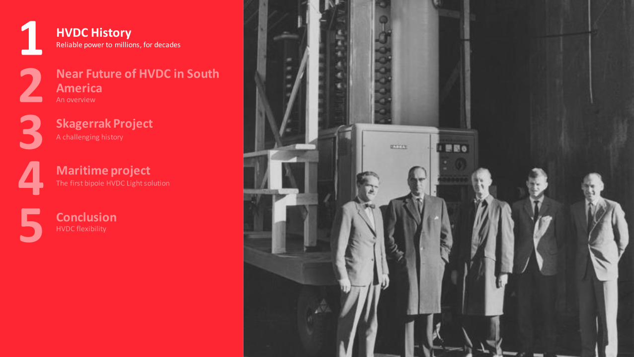
HVDC HistoryReliable power to millions, for decades1
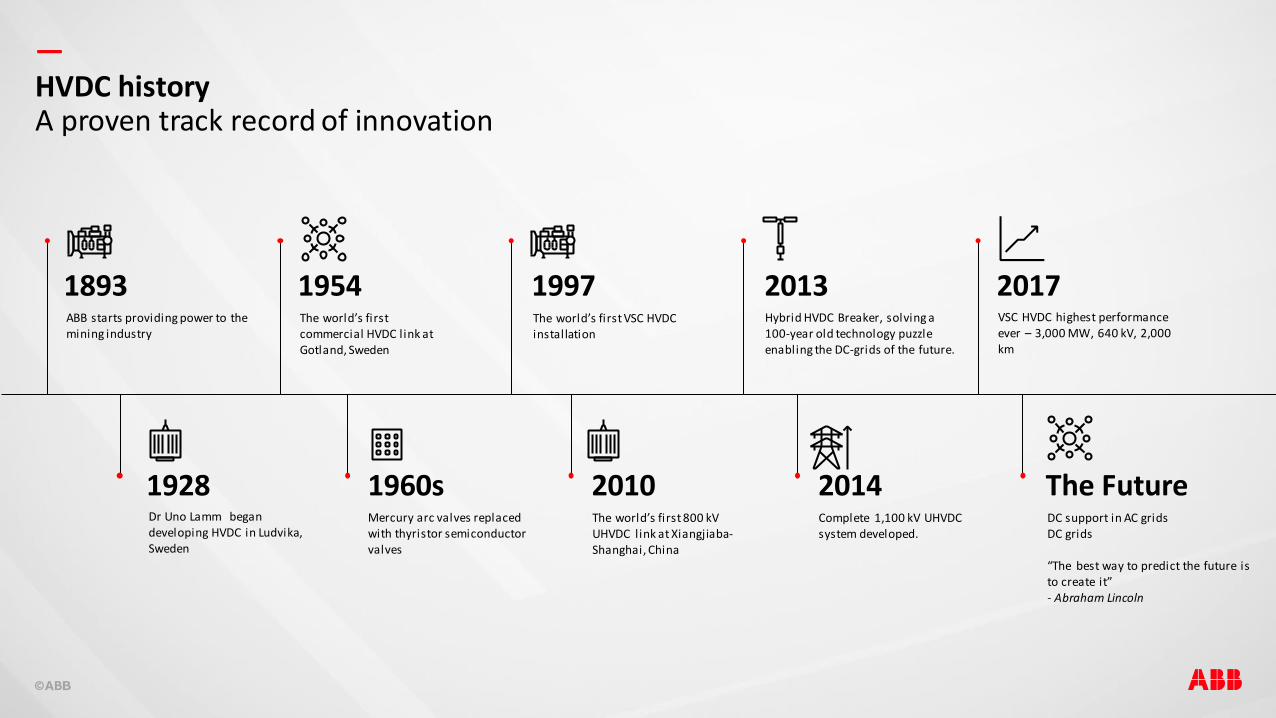
—HVDC historyA proven track record of innovation
1893
1928
1997
2010
2013 2017ABB starts providing power to the mining industry
Dr Uno Lamm began developing HVDC in Ludvika, Sweden
The world’s first VSC HVDC installation
DC support in AC gridsDC grids
“The best way to predict the future is to create it”- Abraham Lincoln
VSC HVDC highest performance ever – 3,000 MW, 640 kV, 2,000 km
Hybrid HVDC Breaker, solving a 100-year old technology puzzle enabling the DC-grids of the future.
The world’s first 800 kV UHVDC link at Xiangjiaba-Shanghai, China
1960sMercury arc valves replaced with thyristor semiconductor valves
2014Complete 1,100 kV UHVDC system developed.
1954The world’s first commercial HVDC link at Gotland, Sweden
The Future
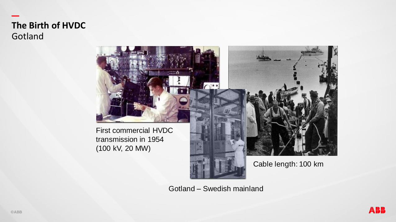
—The Birth of HVDCGotland
First commercial HVDC
transmission in 1954
(100 kV, 20 MW)
Gotland – Swedish mainland
Cable length: 100 km

—
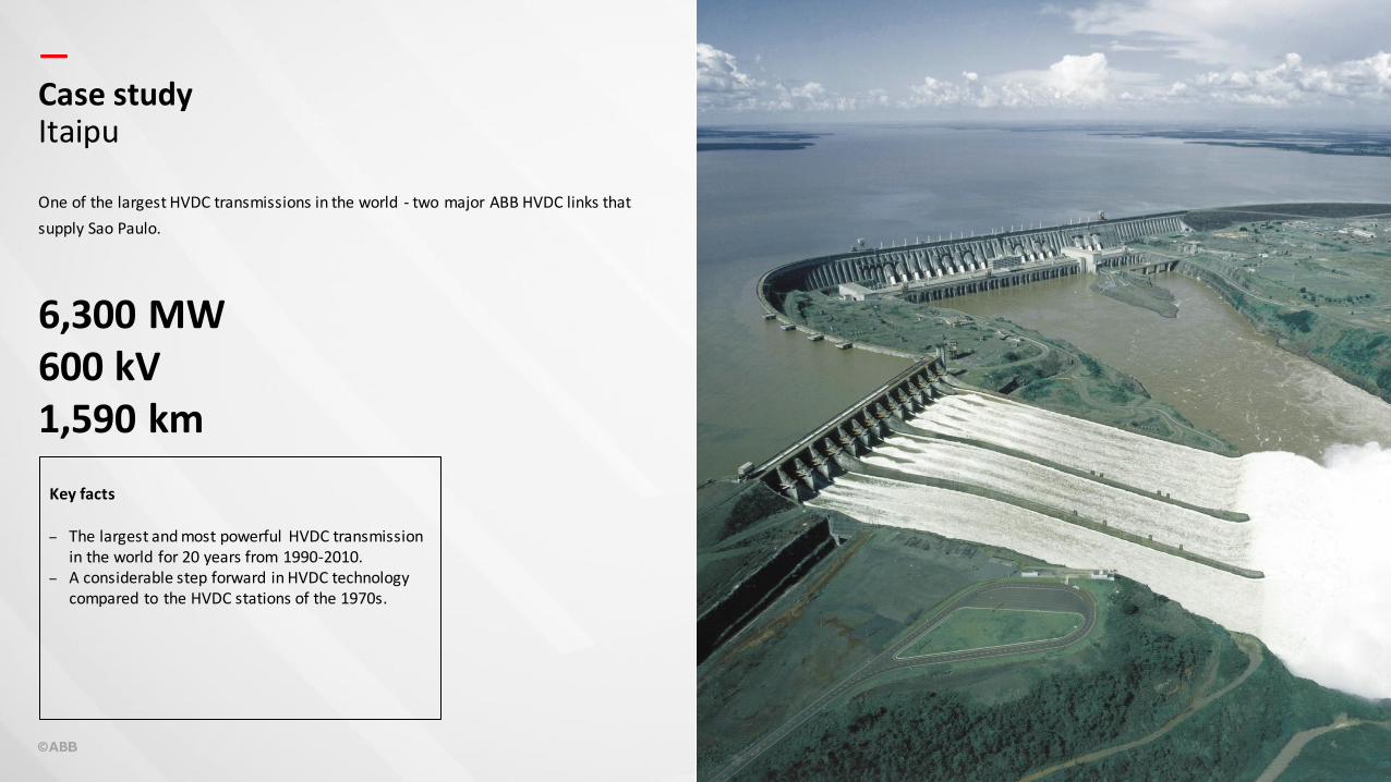
—Case studyItaipu
One of the largest HVDC transmissions in the world - two major ABB HVDC links that
supply Sao Paulo.
6,300 MW600 kV1,590 km
Key facts
– The largest and most powerful HVDC transmission in the world for 20 years from 1990-2010.
– A considerable step forward in HVDC technology compared to the HVDC stations of the 1970s.
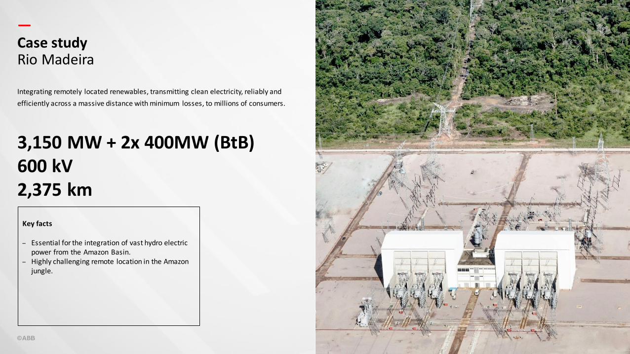
—Case studyRio Madeira
Integrating remotely located renewables, transmitting clean electricity, reliably and
efficiently across a massive distance with minimum losses, to millions of consumers.
3,150 MW + 2x 400MW (BtB)600 kV2,375 km
Key facts
– Essential for the integration of vast hydro electric power from the Amazon Basin.
– Highly challenging remote location in the Amazon jungle.
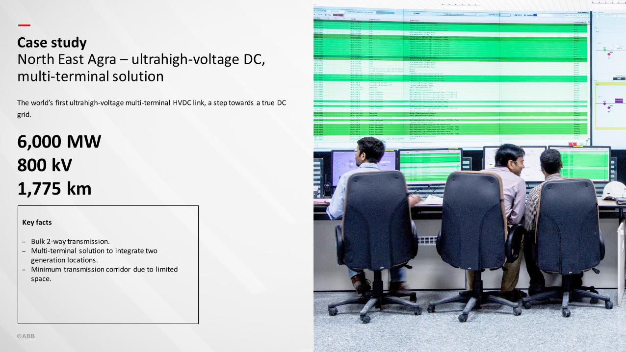
—Case studyNorth East Agra – ultrahigh-voltage DC, multi-terminal solution
The world’s first ultrahigh-voltage multi-terminal HVDC link, a step towards a true DC
grid.
6,000 MW800 kV1,775 km
Key facts
– Bulk 2-way transmission.– Multi-terminal solution to integrate two
generation locations.– Minimum transmission corridor due to limited
space.
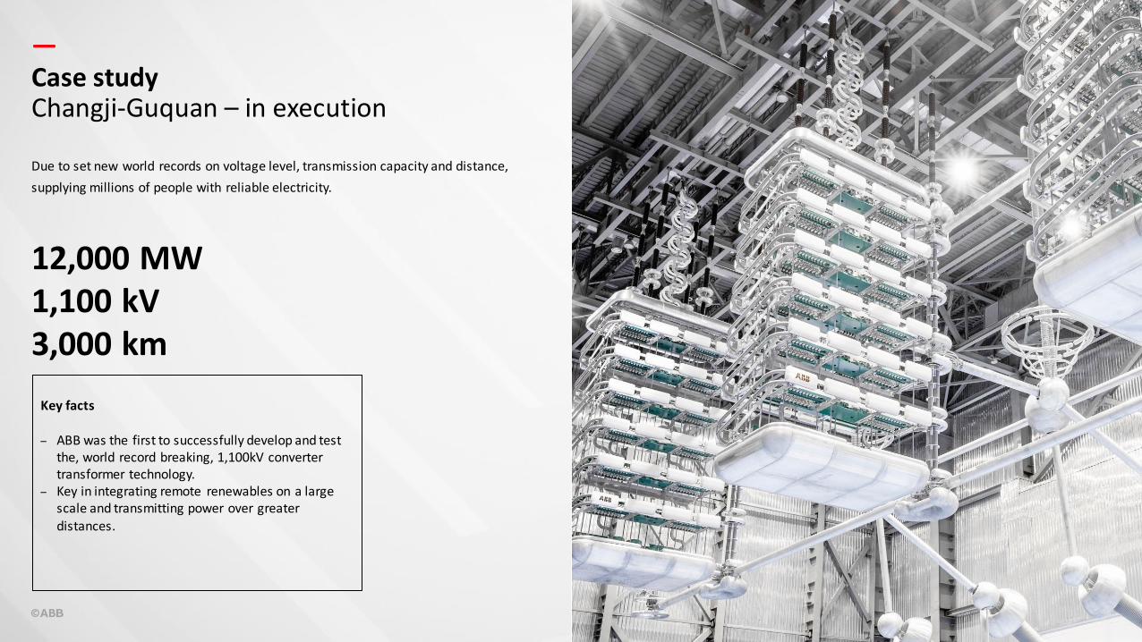
—Case studyChangji-Guquan – in execution
12,000 MW1,100 kV3,000 km
Key facts
– ABB was the first to successfully develop and test the, world record breaking, 1,100kV converter transformer technology.
– Key in integrating remote renewables on a large scale and transmitting power over greater distances.
Due to set new world records on voltage level, transmission capacity and distance,
supplying millions of people with reliable electricity.
—
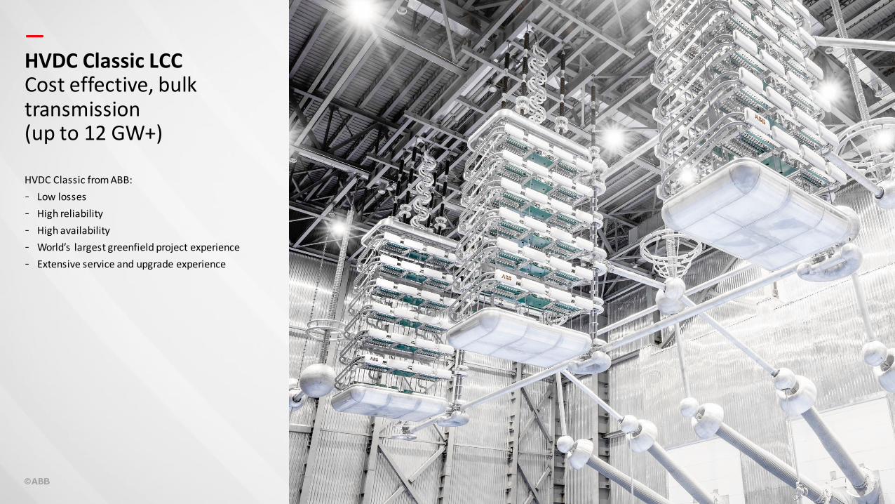
HVDC Classic from ABB:
- Low losses
- High reliability
- High availability
- World’s largest greenfield project experience
- Extensive service and upgrade experience
HVDC Classic LCCCost effective, bulk transmission(up to 12 GW+)
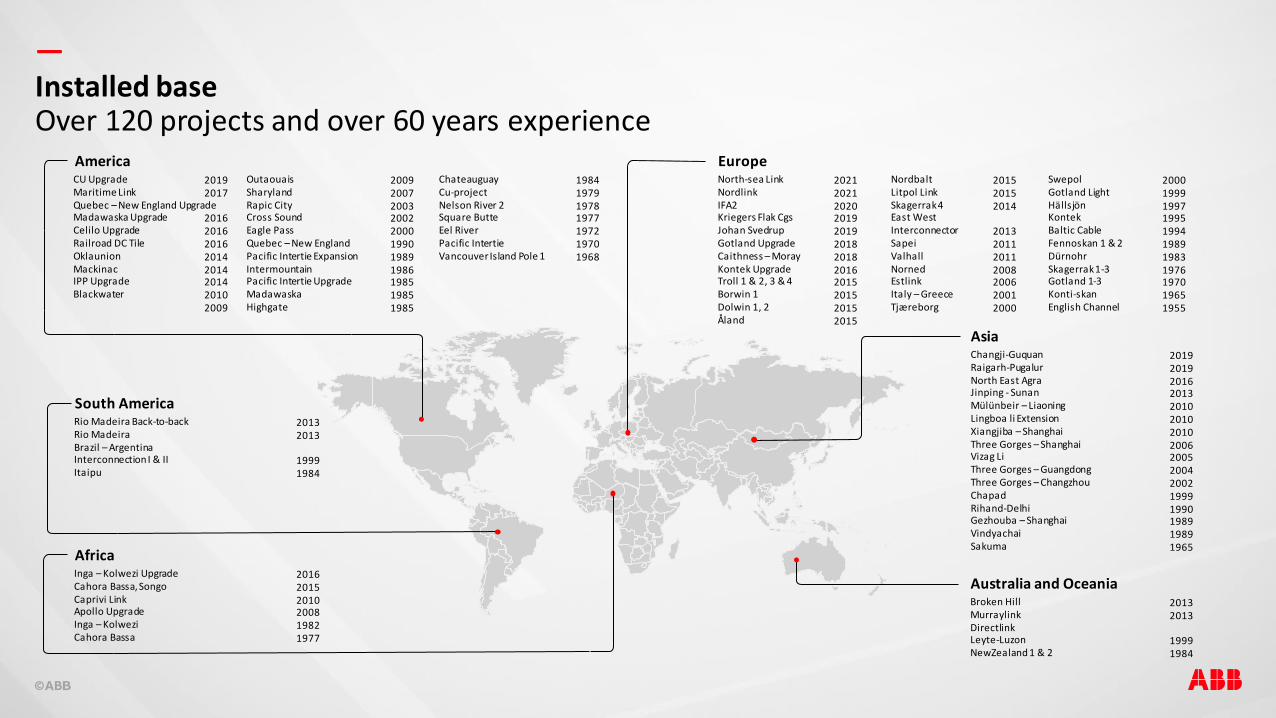
—Installed baseOver 120 projects and over 60 years experience
CU UpgradeMaritime LinkQuebec – New England UpgradeMadawaska UpgradeCelilo UpgradeRailroad DC TileOklaunionMackinacIPP UpgradeBlackwater
20192017
20162016201620142014201420102009
AmericaOutaouaisSharylandRapic CityCross SoundEagle PassQuebec – New EnglandPacific Intertie ExpansionIntermountainPacific Intertie UpgradeMadawaskaHighgate
20092007200320022000199019891986198519851985
ChateauguayCu-projectNelson River 2Square ButteEel RiverPacific IntertieVancouver Island Pole 1
1984197919781977197219701968
Rio Madeira Back-to-backRio MadeiraBrazil – ArgentinaInterconnection I & IIItaipu
20132013
19991984
South America
Africa
North-sea LinkNordlinkIFA2Kriegers Flak CgsJohan SvedrupGotland UpgradeCaithness – MorayKontek UpgradeTroll 1 & 2, 3 & 4Borwin 1Dolwin 1, 2Åland
202120212020201920192018201820162015201520152015
EuropeNordbaltLitpol LinkSkagerrak 4East WestInterconnectorSapeiValhallNornedEstlinkItaly – GreeceTjæreborg
201520152014
2013201120112008200620012000
SwepolGotland LightHällsjönKontekBaltic CableFennoskan 1 & 2DürnohrSkagerrak 1-3Gotland 1-3Konti-skanEnglish Channel
20001999199719951994198919831976197019651955
Changji-GuquanRaigarh-PugalurNorth East AgraJinping - SunanMülünbeir – LiaoningLingboa li ExtensionXiangjiba – ShanghaiThree Gorges – ShanghaiVizag LiThree Gorges – GuangdongThree Gorges – ChangzhouChapadRihand-DelhiGezhouba – ShanghaiVindyachaiSakuma
2019201920162013201020102010200620052004200219991990198919891965
Asia
Broken HillMurraylinkDirectlinkLeyte-LuzonNewZealand 1 & 2
20132013
19991984
Australia and OceaniaInga – Kolwezi UpgradeCahora Bassa, SongoCaprivi LinkApollo UpgradeInga – KolweziCahora Bassa
201620152010200819821977
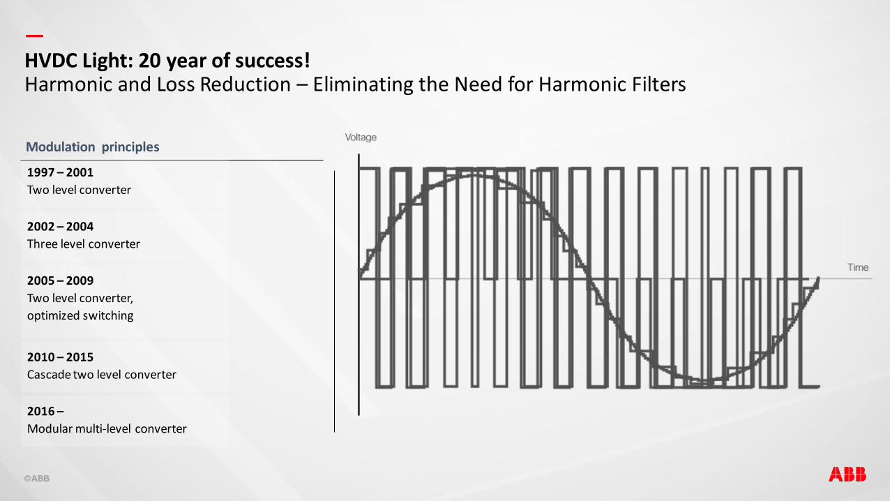
—HVDC Light: 20 year of success!Harmonic and Loss Reduction – Eliminating the Need for Harmonic Filters
Modulation principles
2002 – 2004
Three level converter
2005 – 2009
Two level converter,
optimized switching
2010 – 2015
Cascade two level converter
2016 –
Modular multi-level converter
1997 – 2001
Two level converter

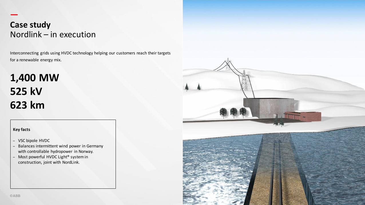
—Case studyNordlink – in execution
1,400 MW525 kV623 km
Key facts
– VSC bipole HVDC – Balances intermittent wind power in Germany
with controllable hydropower in Norway.– Most powerful HVDC Light® system in
construction, joint with NordLink.
Interconnecting grids using HVDC technology helping our customers reach their targets
for a renewable energy mix.
—
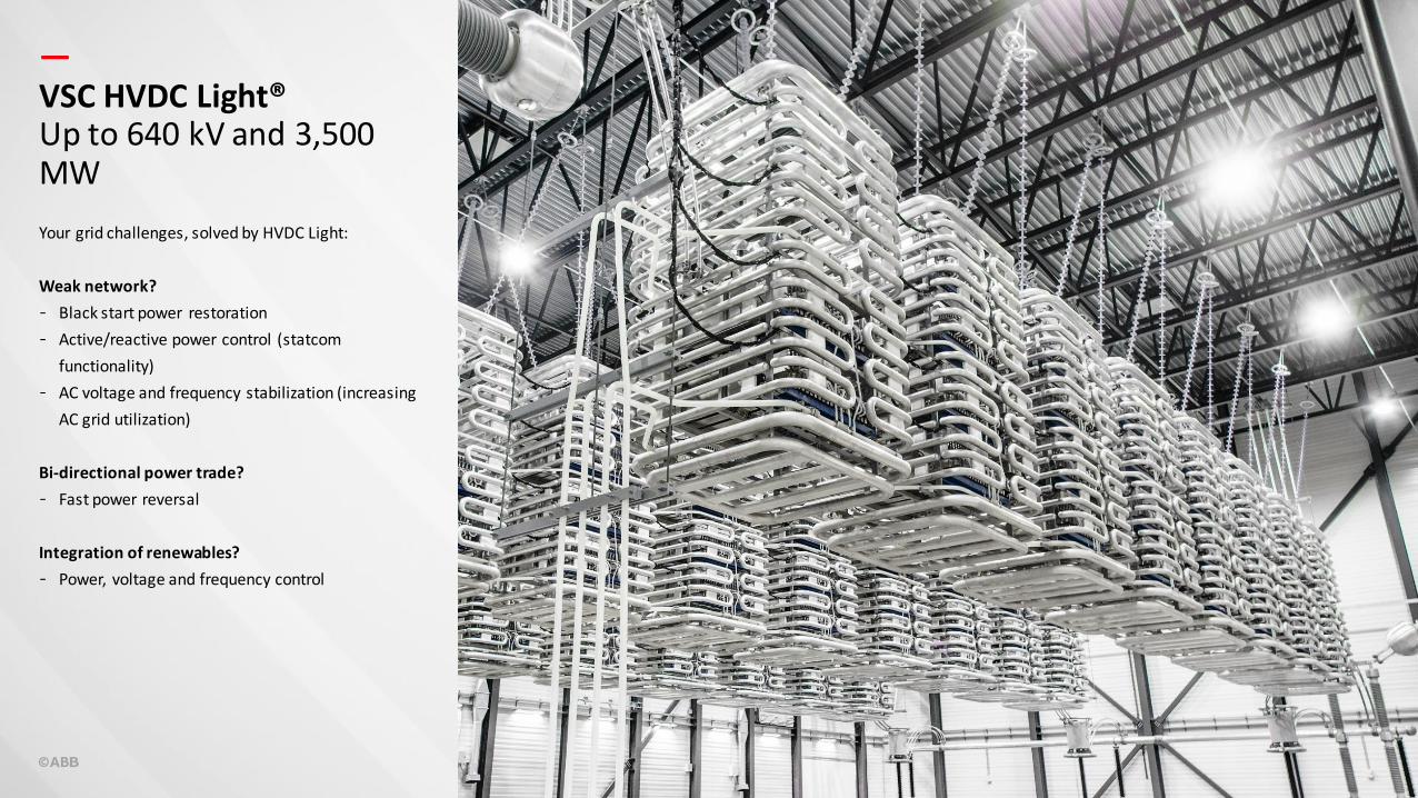
Your grid challenges, solved by HVDC Light:
Weak network?
- Black start power restoration
- Active/reactive power control (statcom
functionality)
- AC voltage and frequency stabilization (increasing
AC grid utilization)
Bi-directional power trade?
- Fast power reversal
Integration of renewables?
- Power, voltage and frequency control
VSC HVDC Light®Up to 640 kV and 3,500 MW
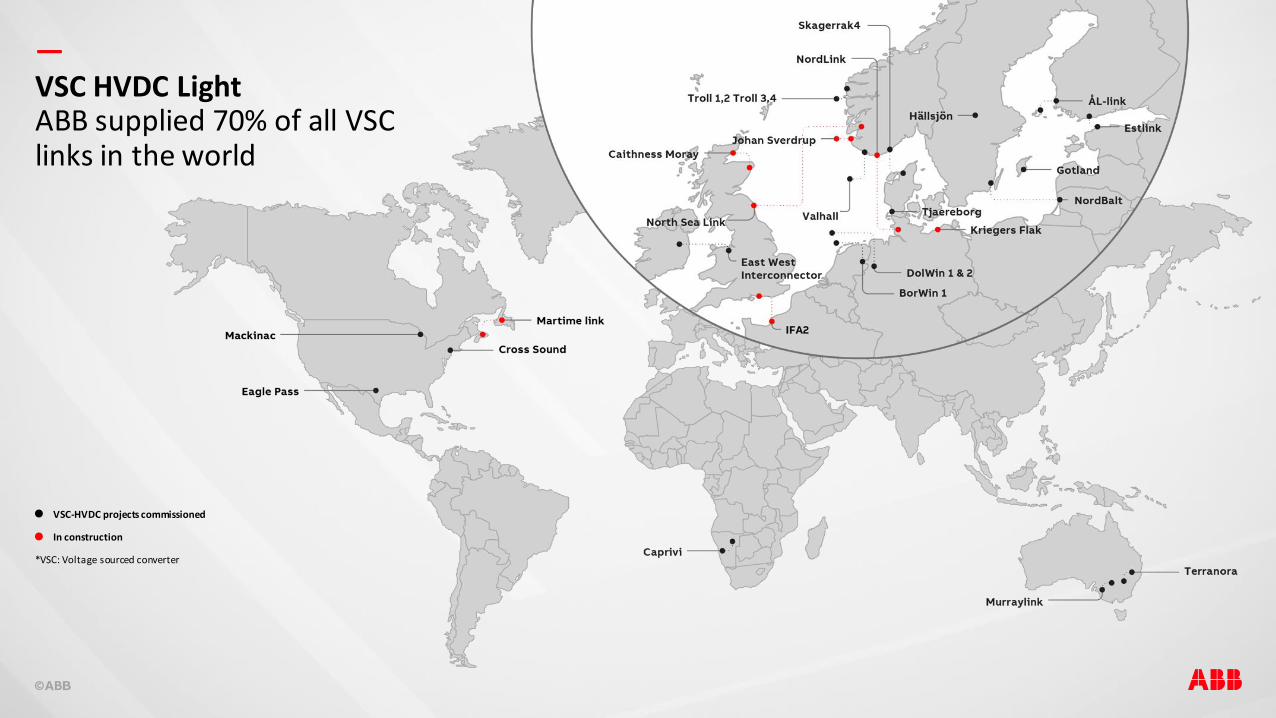
—VSC HVDC LightABB supplied 70% of all VSC links in the world
VSC-HVDC projects commissioned
In construction
*VSC: Voltage sourced converter
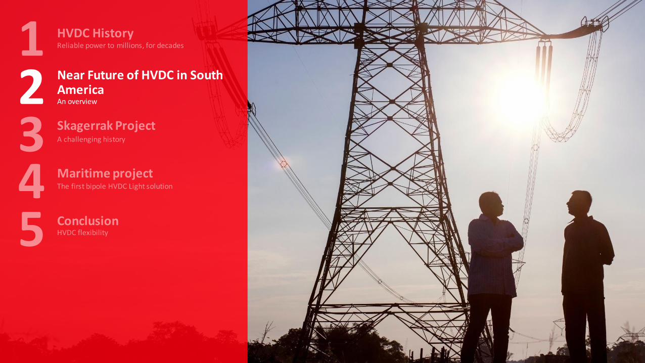
Near Future of HVDC in South AmericaAn overview2
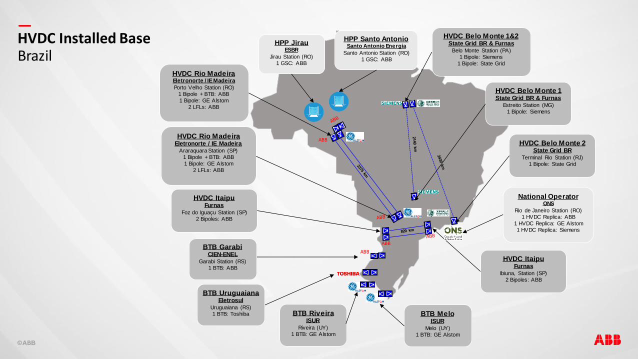
—HVDC Installed BaseBrazil
ABB
ABB
ABB
HVDC Rio MadeiraEletronorte / IE Madeira
Porto Velho Station (RO)
1 Bipole + BTB: ABB
1 Bipole: GE Alstom
2 LFLs: ABB
HVDC Rio MadeiraEletronorte / IE Madeira
Araraquara Station (SP)
1 Bipole + BTB: ABB
1 Bipole: GE Alstom
2 LFLs: ABB
HVDC ItaipuFurnas
Foz do Iguaçu Station (SP)
2 Bipoles: ABB
BTB MeloISUR
Melo (UY)
1 BTB: GE Alstom
HVDC ItaipuFurnas
Ibiuna, Station (SP)
2 Bipoles: ABB
HVDC Belo Monte 2State Grid BR
Terminal Rio Station (RJ)
1 Bipole: State Grid
HVDC Belo Monte 1State Grid BR & Furnas
Estreito Station (MG)
1 Bipole: Siemens
HPP JirauESBR
Jirau Station (RO)
1 GSC: ABB
HPP Santo AntonioSanto Antonio Energia
Santo Antonio Station (RO)
1 GSC: ABB
National OperatorONS
Rio de Janeiro Station (RO)
1 HVDC Replica: ABB
1 HVDC Replica: GE Alstom
1 HVDC Replica: Siemens
HVDC Belo Monte 1&2State Grid BR & Furnas
Belo Monte Station (PA)
1 Bipole: Siemens
1 Bipole: State Grid
BTB GarabiCIEN-ENEL
Garabi Station (RS)
1 BTB: ABB
BTB RiveiraISUR
Riveira (UY)
1 BTB: GE Alstom
BTB UruguaianaEletrosul
Uruguaiana (RS)
1 BTB: Toshiba
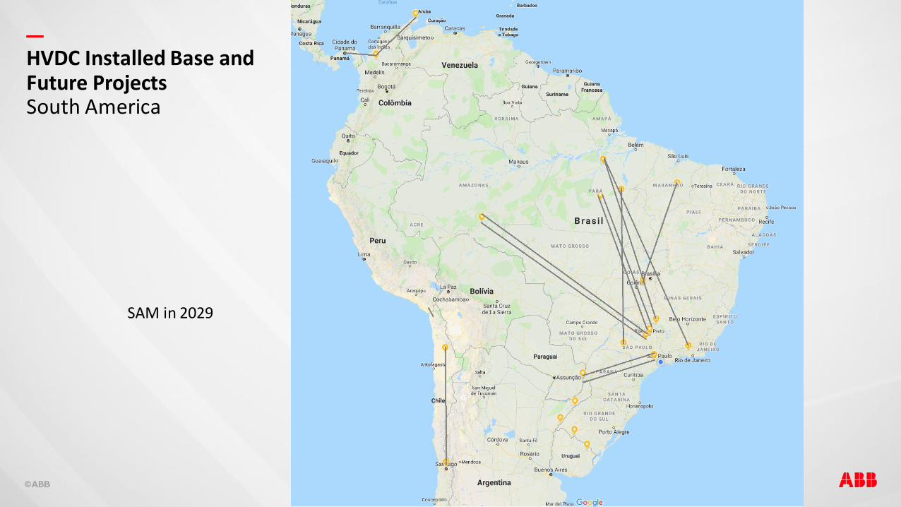
—HVDC Installed Base and Future ProjectsSouth America
SAM in 2029

—
T. Rio
Belo Monte
Madeira
Araraquara
Itaipu
Int. N–S
Parauapebas
Assis
Estreito
Int NE – SE
Graça Aranha
Silv ania
Tapajos
HPP Tapajós Transmission System
Voltage: ± 800 kV DC
Power: 8,000 MW for 2 bipoles
Expected Auction/Award: 2025 BP12027 BP2
Transmission Line: 1,500 km BP12,500 km BP2
N/SE and NE/SE Transmission Expansion
Transmission Line: 2,100 km N/SE1,500 km NE/SE
Voltage: ± 800 kV DC
Power: 8,000 MW for 2 bipoles
Expected Auction/Award: 2021 BP B2023 BP A
HVDC Future ProjectsBrazil
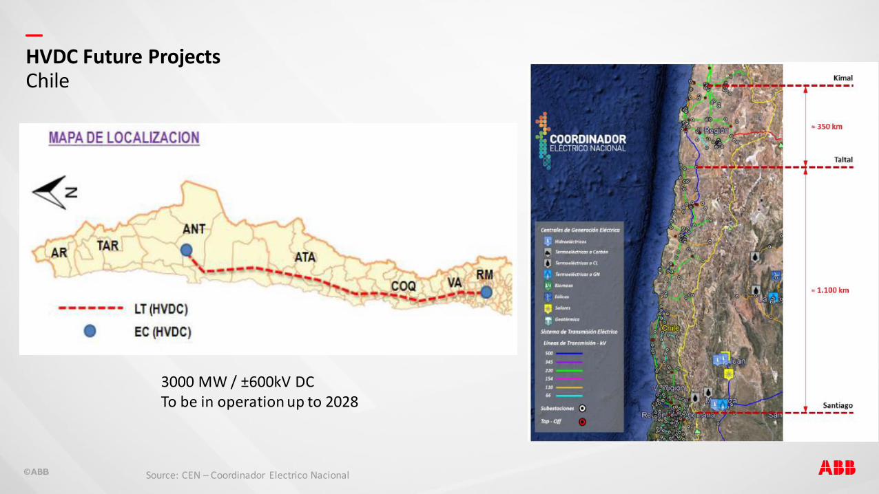
—HVDC Future ProjectsChile
3000 MW / ±600kV DCTo be in operation up to 2028
Source: CEN – Coordinador Electrico Nacional
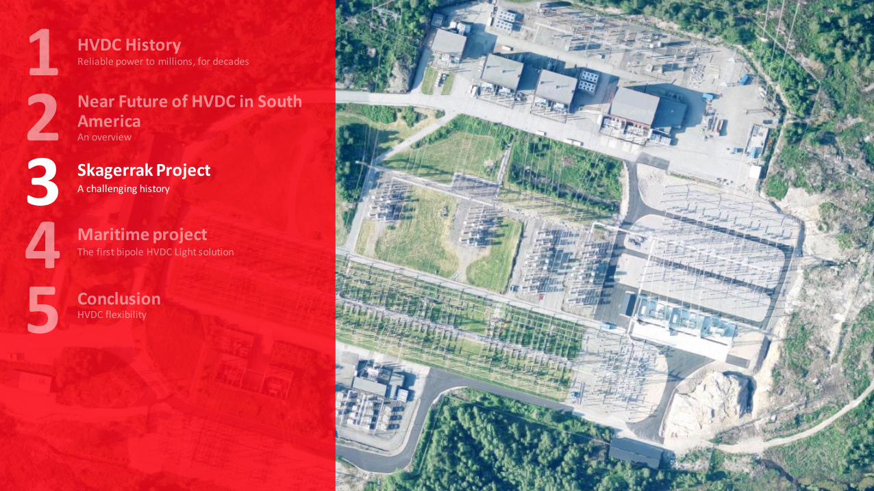
Skagerrak ProjectA challenging history3
—
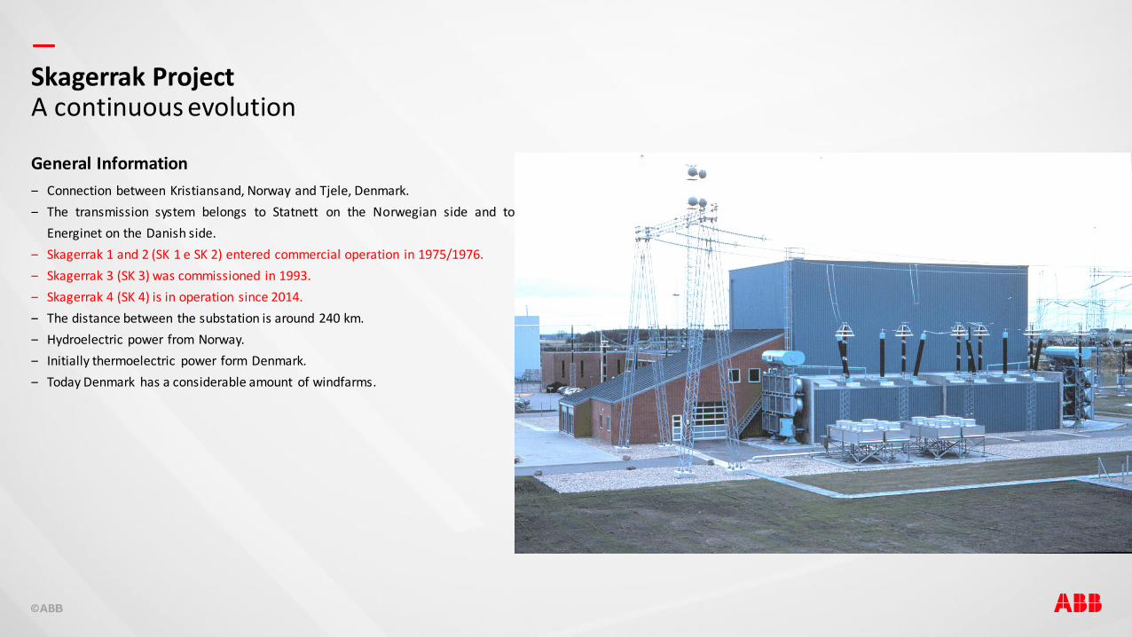
‒ Connection between Kristiansand, Norway and Tjele, Denmark.
‒ The transmission system belongs to Statnett on the Norwegian side and to
Energinet on the Danish side.
‒ Skagerrak 1 and 2 (SK 1 e SK 2) entered commercial operation in 1975/1976.
‒ Skagerrak 3 (SK 3) was commissioned in 1993.
‒ Skagerrak 4 (SK 4) is in operation since 2014.
‒ The distance between the substation is around 240 km.
‒ Hydroelectric power from Norway.
‒ Initially thermoelectric power form Denmark.
‒ Today Denmark has a considerable amount of windfarms.
Skagerrak ProjectA continuous evolution
General Information
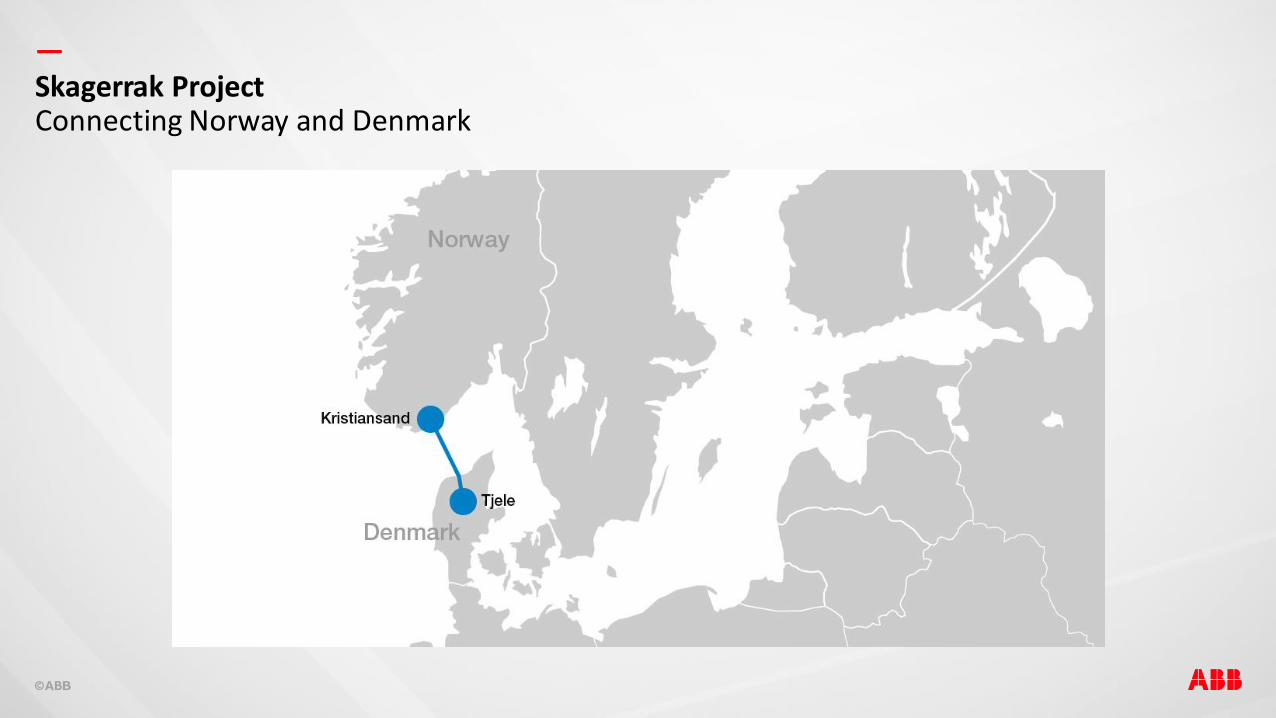
—Skagerrak ProjectConnecting Norway and Denmark

—
‒ Bipole with Line-Commuted Converters (LCC).
‒ Uses thyristor in the converters.
‒ Voltage of ± 250 kV DC (until Skagerrak 3).
‒ Current of 1000 A.
‒ Total power of 500 MW.
‒ 127 km submarine cables and 113 km overhead lines.
‒ Earth electrode on both sides.
‒ Commissioned in 1975/1976.
‒ Revitalized in 2007.
Skagerrak 1 & 2The first bipole
General Information
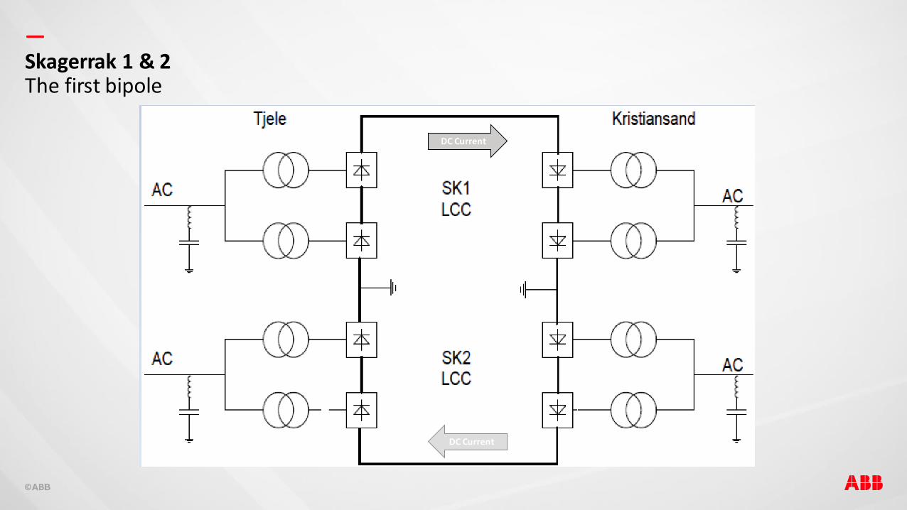
—Skagerrak 1 & 2The first bipole
DC Current
DC Current

—
‒ Monopole with LCC converter.
‒ Voltage of 350 kV DC.
‒ Current of 1430 A.
‒ Power capacity of 500 MW.
‒ 127 km submarine cable and 113 km overhead line.
‒ Commissioned in 1993.
Skagerrak 3The third pole. Changes were needed…
General Information But…
‒ No metallic return dedicated cable was built.
‒ There is a limitation to the amount of time the earth return
can be used.
‒ The rated voltage, current and power for SK3 is different
from SK 1 and 2.
How to operate the new system with a new pole with different specs?
—
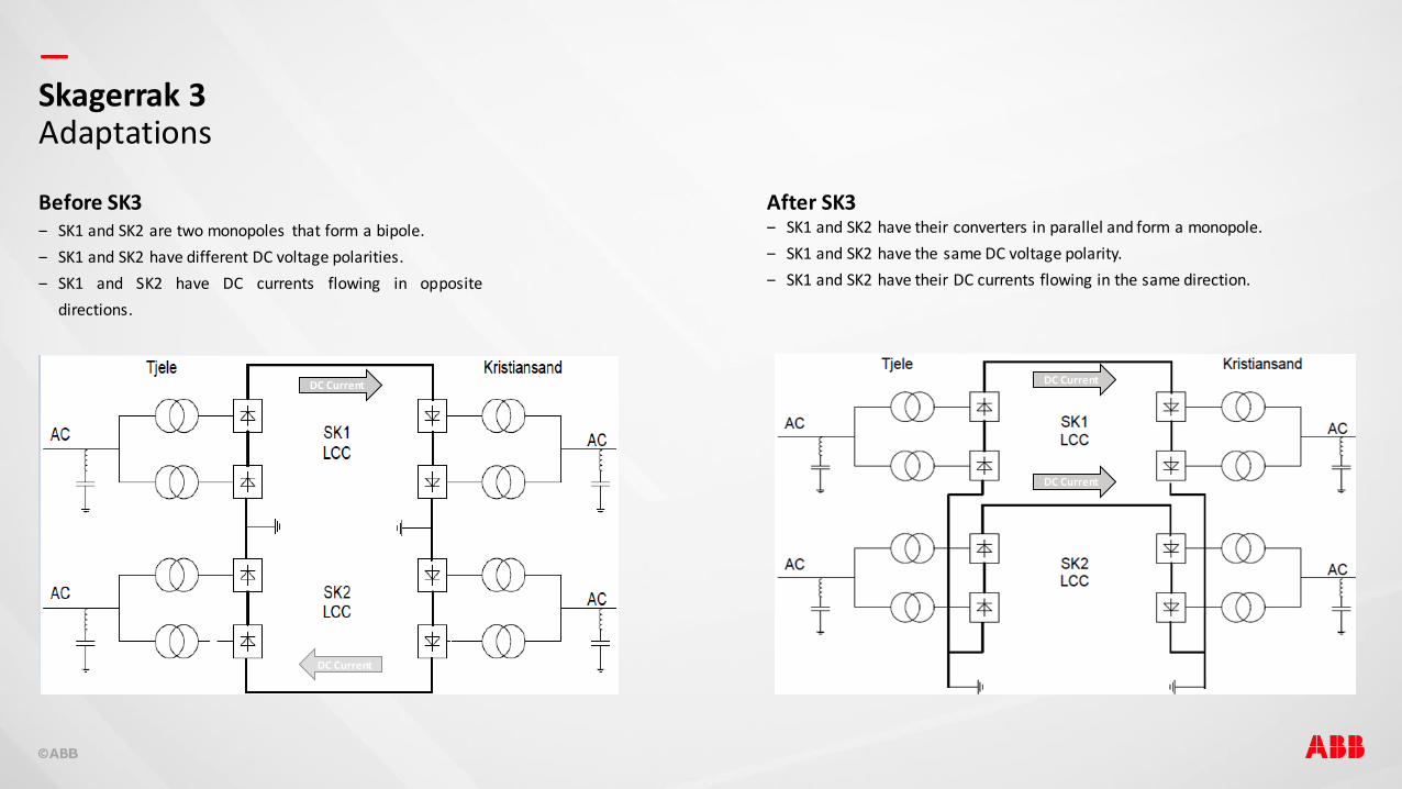
‒ SK1 and SK2 are two monopoles that form a bipole.
‒ SK1 and SK2 have different DC voltage polarities.
‒ SK1 and SK2 have DC currents flowing in opposite
directions.
Skagerrak 3Adaptations
Before SK3 After SK3‒ SK1 and SK2 have their converters in parallel and form a monopole.
‒ SK1 and SK2 have the same DC voltage polarity.
‒ SK1 and SK2 have their DC currents flowing in the same direction.
DC Current
DC Current
DC Current
DC Current
—
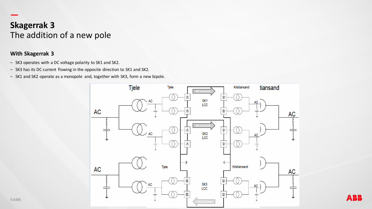
‒ SK3 operates with a DC voltage polarity to SK1 and SK2.
‒ SK3 has its DC current flowing in the opposite direction to SK1 and SK2.
‒ SK1 and SK2 operate as a monopole and, together with SK3, form a new bipole.
Skagerrak 3The addition of a new pole
With Skagerrak 3
DC Current
DC CurrentDC Current
DC Current
DC Current
—
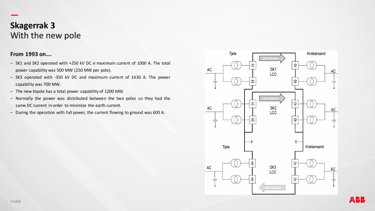
From 1993 on….
‒ SK1 and SK2 operated with +250 kV DC e maximum current of 1000 A. The total
power capability was 500 MW (250 MW per pole).
‒ SK3 operated with -350 kV DC and maximum current of 1430 A. The power
capability was 700 MW.
‒ The new bipole has a total power capability of 1200 MW.
‒ Normally the power was distributed between the two poles so they had the
same DC current in order to minimize the earth current.
‒ During the operation with full power, the current flowing to ground was 600 A.
Skagerrak 3With the new pole
DC Current
DC Current
DC Current
—
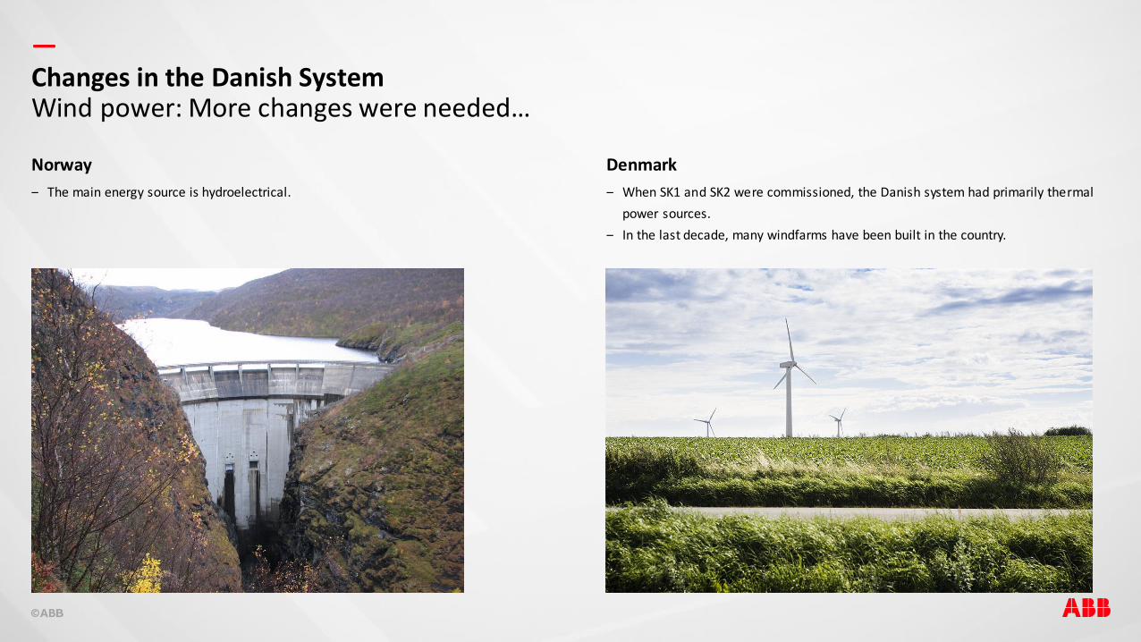
Norway
‒ The main energy source is hydroelectrical.
Denmark
‒ When SK1 and SK2 were commissioned, the Danish system had primarily thermal
power sources.
‒ In the last decade, many windfarms have been built in the country.
Changes in the Danish SystemWind power: More changes were needed…
—
What was HVDC initially intended for?
‒ Initially the Skagerrak transmission system was designed for optimal economical
energy dispatching among the two countries.
‒ Stabilization of the AC grids after contingencies.
What happened more recently?
‒ Wind generation in Denmark sometimes exceeds the consumption of the loads
connected to it.
‒ The HVDC system compensates for swift variations in wind power and assures
the balance between load and generation.
‒ Hydro power in Norway compensates for quick changes in windfarm output in
Denmark.
‒ In some situations the active power in the HVDC link is inverted and Denmark
exports energy to Norway.
Changes in the Danish SystemAdvantages of HVDC with renewable power
—
Why a forth pole?
‒ The need for an increase in the energy exchange capability between Norway and
Denmark requires the construction of a new HVDC pole.
LCC or VSC?
‒ SK1, 2 and 3 are located electrically far away from big conventional generators.
‒ The LCC converters demand a minimum AC network short-circuit level to work
properly.
‒ There are other two HVDC links (Norned and Konti-Skan) that are relatively close
to Skagerrak and multi-infeed interactions might may appear.
‒ Voltage and electromechanical stability problems may occur and synchronous
condensers were installed in Norway to increase the short-circuit level.
‒ A new HVDC pole using LCC technology would require the installation of a few
synchronous condensers in both the Norwegiand and Danish systems.
Changes in the Danish SystemThe fourth pole
—
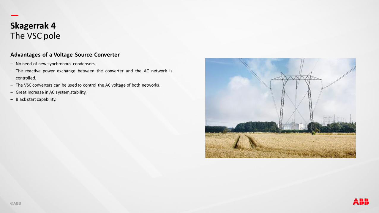
Advantages of a Voltage Source Converter
‒ No need of new synchronous condensers.
‒ The reactive power exchange between the converter and the AC network is
controlled.
‒ The VSC converters can be used to control the AC voltage of both networks.
‒ Great increase in AC system stability.
‒ Black start capability.
Skagerrak 4The VSC pole
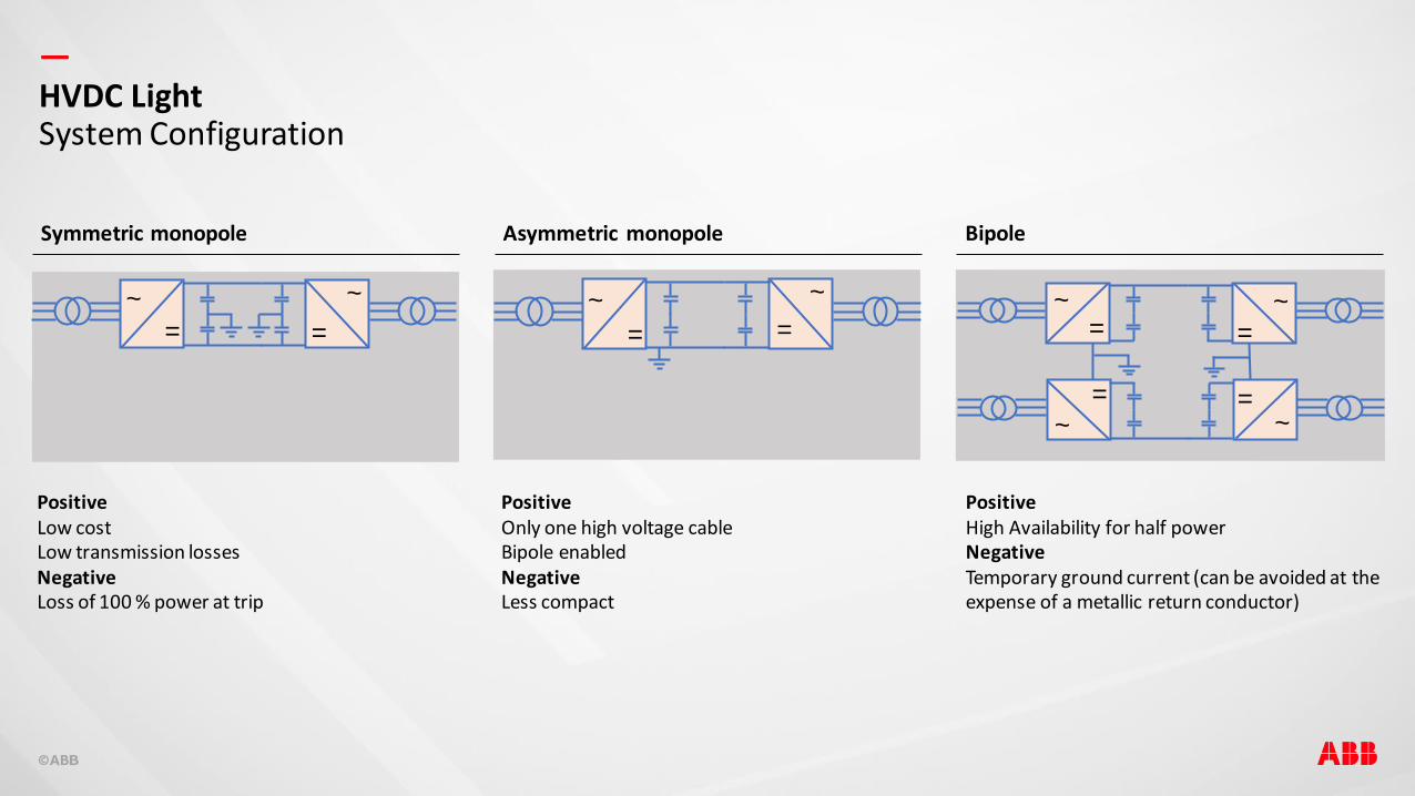
—HVDC LightSystem Configuration
Symmetric monopole Asymmetric monopole Bipole
=
~
=
~
=
~=
~
=~
=
~
=~
=~
PositiveLow costLow transmission lossesNegativeLoss of 100 % power at trip
PositiveHigh Availability for half powerNegativeTemporary ground current (can be avoided at the expense of a metallic return conductor)
PositiveOnly one high voltage cableBipole enabledNegativeLess compact

—
The new pole
‒ VSC converter – asymmetric monopole
‒ Rated DC voltage of + 500 kV.
‒ DC current of 1400 A.
‒ Rated active power of 700 MW.
‒ 140 km submarine cable and 104 km overhead line.
‒ Commissioned in 2014.
Skagerrak 4Specifications
—
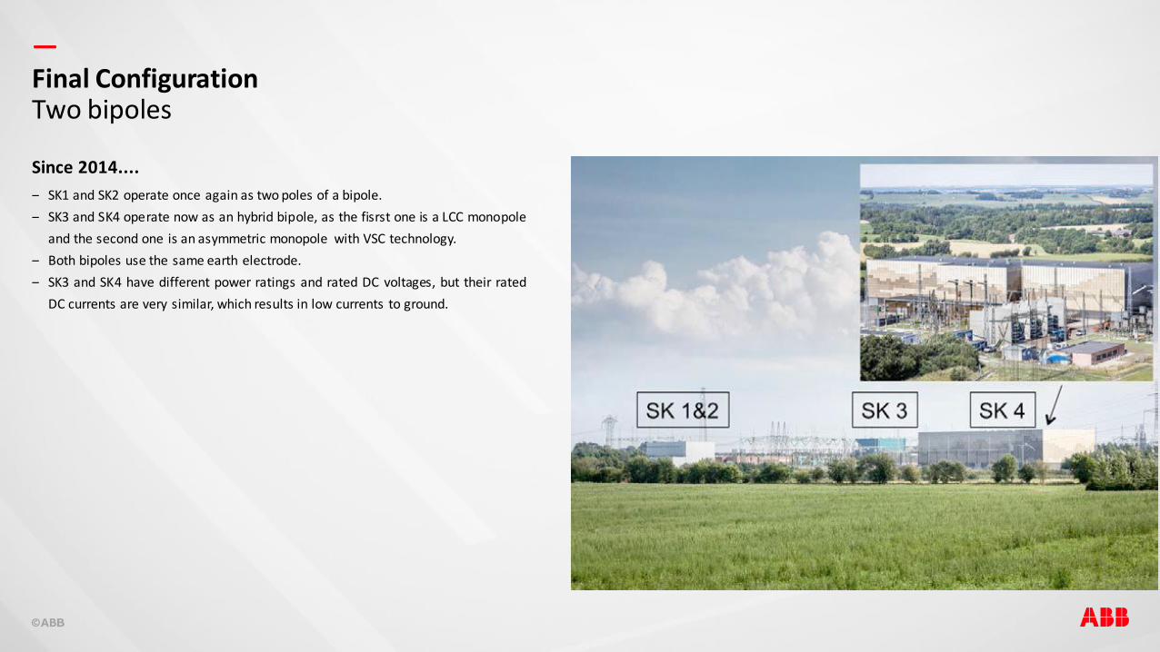
Since 2014....
‒ SK1 and SK2 operate once again as two poles of a bipole.
‒ SK3 and SK4 operate now as an hybrid bipole, as the fisrst one is a LCC monopole
and the second one is an asymmetric monopole with VSC technology.
‒ Both bipoles use the same earth electrode.
‒ SK3 and SK4 have different power ratings and rated DC voltages, but their rated
DC currents are very similar, which results in low currents to ground.
Final ConfigurationTwo bipoles
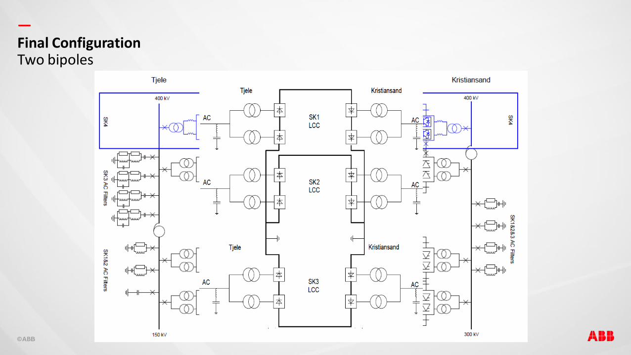
—Final ConfigurationTwo bipoles

—Final ConfigurationHow flexible and HVDC transmission can be…
Poles 1 & 2 Pole 3 Pole 4
Rated Power MW 2 x 250 500 700
DC Voltage kV 250 350 500
DC Current A 1000 1430 1400
Converter Technology LCC LCC VSC
AC Voltage (Kristiansand, NO) kV 300 300 400
AC Voltage (Tjele, DK) kV 150 400 400
DC Submarine Cables km 127 127 140
DC Overhead Lines km 113 113 -
DC underground Cables km - - 104
Comissioning Year 1976 - 1977 1993 2014
Maritime projectThe first bipole HVDC Light solution4
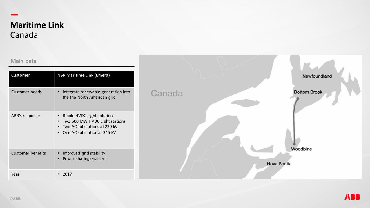
—Maritime LinkCanada
Main data
Customer NSP Maritime Link (Emera)
Customer needs • Integrate renewable generation into the the North American grid
ABB’s response • Bipole HVDC Light solution• Two 500 MW HVDC Light stations• Two AC substations at 230 kV• One AC substation at 345 kV
Customer benefits • Improved grid stability• Power sharing enabled
Year • 2017

—Maritime LinkCanada

—Case studyMaritime
Enabling clean, renewable electricity generated in Newfoundland and Labrador to be
transmitted to the North American grid in Nova Scotia.
500 MW200 kV360 km
Key facts
– World’s first VSC bipole HVDC interconnection overcoming unique control challenges.
– Demanding environment.– Unique socio-economic and environmental
requirements.
—Case studyNordlink – in execution
1,400 MW525 kV623 km
Key facts
– VSC bipole HVDC – Balances intermittent wind power in Germany
with controllable hydropower in Norway.– Most powerful HVDC Light® system in
construction, joint with NordLink.
Interconnecting grids using HVDC technology helping our customers reach their targets
for a renewable energy mix.
ConclusionHVDC flexibility5
—
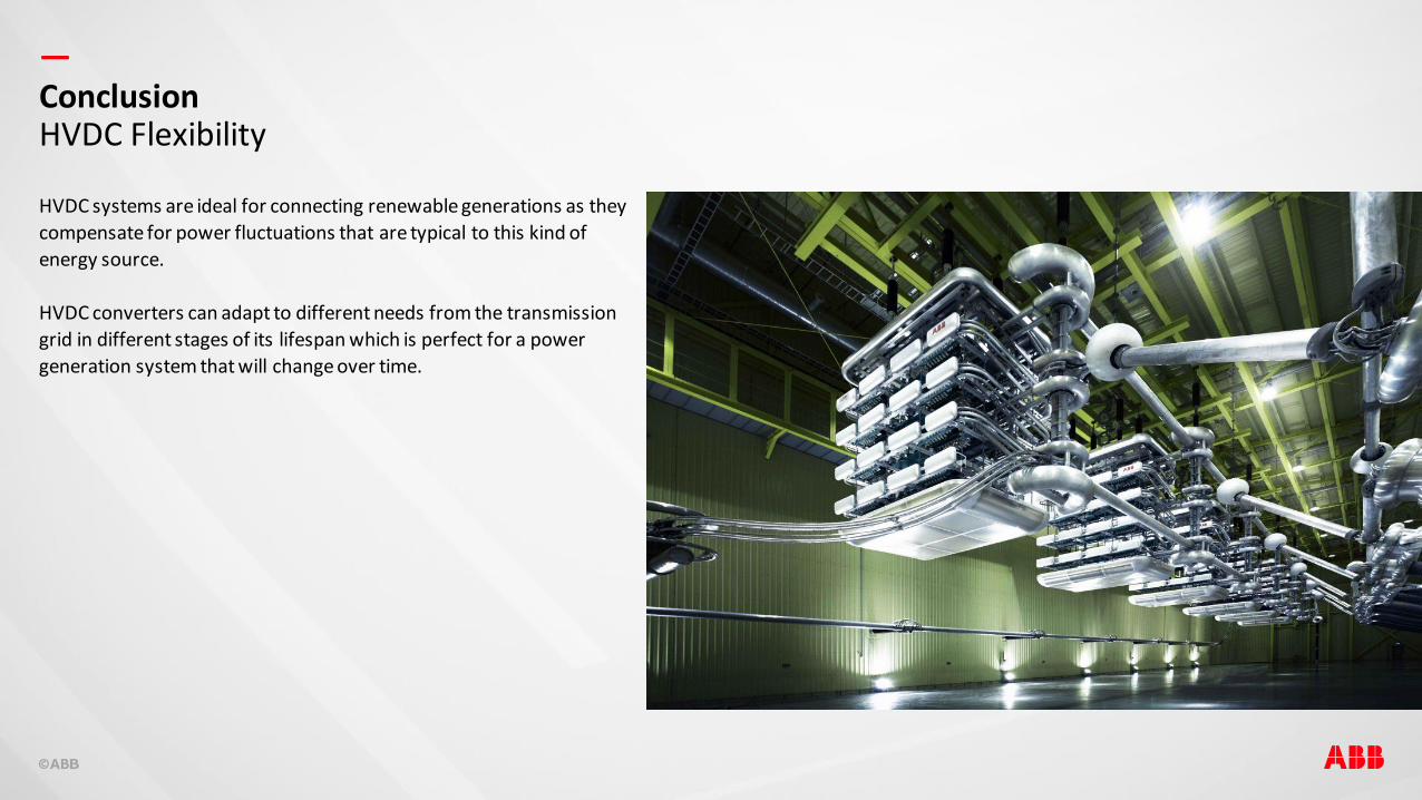
HVDC systems are ideal for connecting renewable generations as they
compensate for power fluctuations that are typical to this kind of
energy source.
HVDC converters can adapt to different needs from the transmission
grid in different stages of its lifespan which is perfect for a power
generation system that will change over time.
ConclusionHVDC Flexibility