Embed Size (px)
DESCRIPTION
maxxforce 11 y 13
Citation preview
RetarderControl
Engine Retarder Cooling SystemEngineCoolantTemp.(ECT
Sensor)
EngineCoolantTemp. 2(ECT2
Sensor)
ManifoldAir Temp.
(MAT)Sensor
Cold StartSolenoid
(CSS)Value
EngineOil
Temp.(EOT)
Sensor
EngineOil
Pressure(EOP)
Sensor
Fuel RailPressure
(FRP)Sensor
EngineFuel
Pressure(EFP)
Sensor
ManifoldAbsolutePressure/Intake AirTemp 2
(MAP/IAT2)Sensor
4 2
1
1
2
5
63
4 2
1 3
44
2
1
1
3
4 2
1 3
4 21 2 1 2
3
4 2
1 11
33
B
A
+-
+-
EIM Connectors X1-X4
EngineControl
Module ECM98-pin
Connector E1
36-pinConnector E2
GlowPlug
Cold Start Assist System
Engine Coolant Level (ECL)
IgnitionSwitch
EIM/ACMRelay
Connector
ChassisHarness
Connector C 20A
10A
25A
Lube System Timing SystemFuel SystemAir-Charge System
EGR System Air System Fuel System
EGRControlValve
GND
GND
CrankshaftPositionSensor(CKP)
ExhaustGas
RecirculationPosition(EGRP)Sensor
BoostControl
Solenoid(BCS)Valve
IntakeThrottleValve(ITV)
FuelPressure
Control Valve(FPCV)
GNDGND
B+
OWL
VSS_CAL
XCSTACH
WEL
SIG GNDVREF
REMPWTS
RPRE
RAS
SCSRVAR
BodyBuilder
Connectors
ATA-HVSS-HVSS-LDDS
ATA-LCAN-HCAN-L
TransConn
AES
CabInterface
Connector
EIM/ACMRelay
APS/IVS
InstrumentCluster
ESC
MPH RPM
OTHER CAN CONNECTIONS
CAN-LCAN-H
Fuselink
Cold StartRelay (CSR)
VariableElectronic Fan Control
Fan
A
DE
F BGJH
C
IATSensor
ContinuedSide 2
B
ContinuedSide 2
A
BATTERIES
5A10A
Public CAN-HPublic CAN-L
20A
Single or Two-SpeedElectronic Fan Control
4
2
1
3
HortonFan
Vehicles haveEITHER a single speed,
two-speed, orvariable speed fan.
Note on Electronic Fan:
85
85 87
30 86
87 30
4
5231
1
B
A
3
AC
D
B
6
4
86
Vehicle Diagnostic Connector
Megafuse
10A
Note on Fuses:This document is “forreference only” concerning physical fuse placement in the vehicle wiring.Fuses labeled in blue are included in the vehicle wiring.
EGR GND
D
VIGNVIGN
Ignition
PrivatePrivate
CamshaftPositionSensor(CMP)
B+
B+21
2 14
3
1
2
4
3
12
4 1
3
2
Exhaust Lambda Sensor(ELS)
BB2-5BB2-8
BB2-2BB2-3
BB1-7BB2-7BB2-6BB2-1
BB2-4BB1-4BB1-3BB1-2BB1-6BB1-5
BB1-1
ECL1
C
120
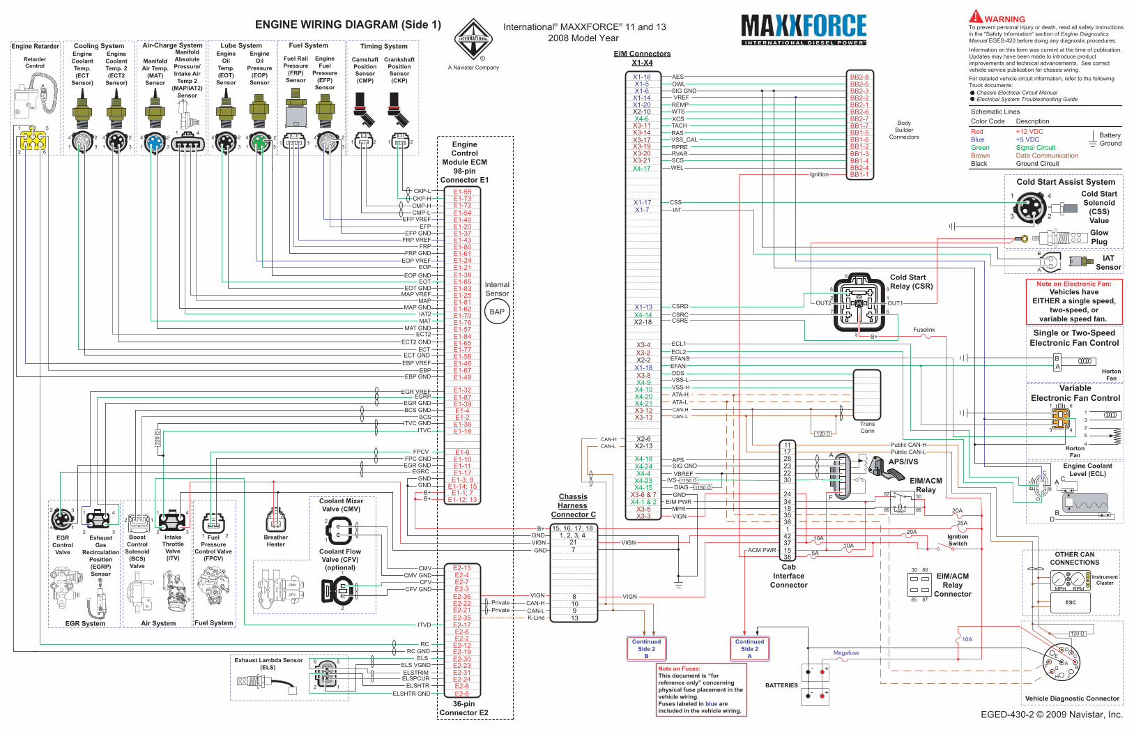
ENGINE WIRING DIAGRAM (Side 1) International® MAXXFORCE® 11 and 132008 Model Year
EGED-430-2 © 2009 Navistar, Inc.
Red +12 VDCBlue +5 VDCGreen Signal CircuitBrown Data CommunicationBlack Ground Circuit
Color CodeSchematic Lines
Description
BatteryGround
For detailed vehicle circuit information, refer to the followingTruck documents:
Chassis Electrical Circuit ManualElectrical System Troubleshooting Guide
Information on this form was current at the time of publication.Updates may have been made to introduce product improvements and technical advancements. See correct vehicle service publication for chassis wiring.
WARNINGTo prevent personal injury or death, read all safety instructions in the "Safety Information" section of Engine Diagnostics Manual EGES-420 before doing any diagnostic procedures.
A
F
CKP-LCKP-HCMP-HCMP-L
EFP VREFEFP
EFP GNDFRP VREF
FRPFRP GND
EOT GNDMAP VREF
MAPMAP GND
IAT2MAT
MAT GNDECT2
ECT2 GND
EBP VREFEBP
EBP GND
ECTECT GND
EOT
EGRC
2
6
1
5
FPCVFPC GND
ITVCITVC GND
EGRP
BCS GNDBCS
EGR VREF
EGR GND
E1-55E1-73E1-72E1-54E1-40E1-20E1-37E1-43E1-80E1-61E1-24E1-21E1-38E1-85E1-83E1-25E1-81E1-62E1-70E1-76E1-57
E1-77E1-58E1-46E1-67E1-49
E1-11
E1-32E1-87E1-39E1-4E1-2
E1-8E1-10
E1-1; 7E1-12; 13
E1-3; 9E1-14; 15
E1-84E1-65
E1-36E1-18
E1-17
EOP GND
CSSIAT
ANEF
Horton
ECL2EFANS
111728232230
2434183536142371538
SIG GNDAPS
IVS
VIGNMPR
EIM PWRGND
Coolant FlowValve (CFV)(optional)
Coolant MixerValve (CMV)2
2
1
1
CMV
CFVCMV GND
CFV GNDVIGN
CAN-LCAN-H
K-Line
15, 16, 17, 181, 2, 3, 4
8
217
10913
ITVD
RCRC GND
BAP
InternalSensor
E2-3
E2-6E2-2E2-12E2-19
E2-7
E2-30
E2-31E2-24E2-8E2-5
E2-23
E2-17
E2-4E2-13
E2-36E2-22E2-21E2-35
12
67
3
5
8 9
OUT1OUT2
B+
CSRD
CSRE
X1-6X1-14
X3-14X3-17
X1-5
X3-19
X1-20
X4-6X2-10
X3-20X3-21X4-17
X1-17
X3-2
X4-10
X3-8X4-9
X4-20X4-21X3-12X3-13
X3- 11
X1-16
X4-23X4-4X4-24X4-18
X3-3X3-5
X4-1 & 2X3-6 & 7
X2-13X2-6
X1-18X2-2
X1-7
X1-13X4-14X2-18
X3-4
ELSELS VGNDELSTRIMELSPCUR
ELSHTRELSHTR GND
CSRC
VIGN
ACM PWR
AB
R
A Navistar Company
EOP VREFEOP
X4-15 DIAG
VBREF
11501150
BreatherHeater
1 2 1 2 1
3113
2 1 2 1 2 1
Cylinder#1
Cylinder#2 Cylinder
#3
Cylinder#4 Cylinder
#5
Cylinder#6
FUEL INJECTORS
56
4
3
2
1
Flywheel
Front
FIRING ORDER: 1 – 5 – 3 – 6 – 2 - 4
2
ECM16 pin
Connector D
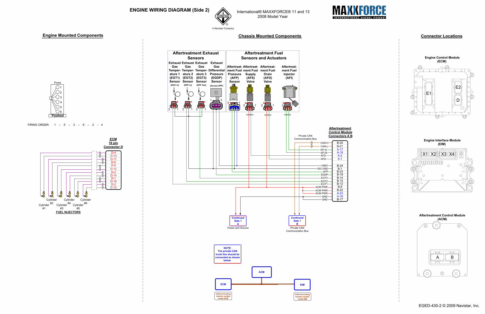
Engine Mounted Components Chassis Mounted Components Connector Locations
D-12D-3D-14
D-15D-2
D-5
D-4D-13D-11
D-16D-1
D-6
AftertreatmentControl ModuleConnectors A B
Aftertreatment ExhaustSensors
ExhaustGas
Temper-ature 1(EGT1)Sensor
ExhaustGas
Temper-ature 2(EGT2)Sensor
ExhaustGas
Temper-ature 3(EGT3)Sensor
ExhaustGas
DifferentialPressure(EGDP)Sensor
Aftertreat-ment FuelPressure
(AFP)Sensor
Aftertreat-ment Fuel
Supply(AFS)Valve
Aftertreat-ment Fuel
Drain(AFD)Valve
Aftertreat-ment FuelInjector
(AFI)
Aftertreatment FuelSensors and Actuators Engine Control Module
(ECM)
Engine Interface Module(EIM)
Aftertreatment Control Module(ACM)
(DOC In) (DPF In) (DPF Out) (Across DPF)
CAN-HCAN-L
Private CANCommunication Bus
NOTE:The private CAN
trunk line should be connected as shown
below:
ECM EIM
ACM
CAN terminatingresistor resides
inside ECM
CAN terminatingresistor resides
inside EIM
Private CANCommunication Bus
B-24B-1
B-18
A-2
B-21A-17
B-23
A-18
B-12B-15B-14
B-20
A-1
B-8B-22A-23A-16B-17
AFSAFI-BAFI-A
AFD
EGT3
EGT1EGT2
EGDPAFP
SIG GNDVREF
GNDGND
ACM PWRACM PWRACM PWR
ContinuedSide 1
BPower and Ground
ContinuedSide 1
A
ENGINE WIRING DIAGRAM (Side 2) International® MAXXFORCE® 11 and 132008 Model Year
EGED-430-2 © 2009 Navistar, Inc.
R
A Navistar Company