Embed Size (px)
Citation preview
May 20, 2011 SUBJECT: Beaver Stadium Scoreboard Replacement University Park
Design Professional Long List
1) Cannon Design 2) Ellerbe Becket 3) Crawford architects LLC 4) Ewing Cole 5) Moody Nolan, Inc. 6) Odell 7) Populous 8) Three Sixty Architecture
Dear Design Professional:
Beaver Stadium, home of Penn State Football, is one of the largest and most recognizable sport venues in the country. The existing main end zone scoreboards were installed prior to the 2001 football season and operational maintenance is becoming increasingly challenging and costly. In addition, there have been dramatic advances in the audio/video technology of these products. In order to address the operational issue and enhance the game day spectator experience, we intend to replace both scoreboards with state-of-the-art, HD video boards that will complement the character of the stadium.
In January 2011, KORDA Engineering of Columbus, OH completed a feasibility study that investigated multiple scoreboard layouts and their impact on the existing structure and interior components. Concurrently, AJP of Richmond, VA developed several display options for the proposed video boards. Both documents are included with this letter as background information.
With this letter, we are inviting the firms identified in the attached list to submit proposals to design the replacement of the existing main scoreboards. We envision that the process will include a validation phase to determine the scope of the project followed by the development of several conceptual alternatives including preliminary pricing. The preferred alternative will be fully developed and implemented. The total project budget is $6,800,000.
Due to the specialized nature of this project, this list includes out-of-state firms who have previously expressed interest in working with Penn State and have extensive experience with the design of this type of facility. We will not require out-of-state firms to collaborate with in-state firms. We expect the design process to commence immediately following the Board of
Trustees meeting on July 15, 2011 with substantial completion by August 1, 2012, in order to allow sufficient time for testing and training prior to the first home football game on September 12, 2012.
Penn State will be retaining AJP directly to serve as consultant on this project. In addition, we will require that Clair Brothers Audio Systems, Inc., who installed the existing stadium sound system, be included with the proposed design team. Their contact is Gene Pelland, Executive Vice President, 717-625-4000 or [email protected].
If your firm is interested in pursuing this project, please provide us with the information requested in the enclosed questionnaire no later than June 14, 2011 at Noon. Please answer all of the questions in the order requested. This will provide uniform information on all firms for evaluation by the Selection Committee. We encourage you to be as brief as possible without sacrificing accuracy and completeness. Please submit twelve (12) copies of all materials. In addition, I am including a non-binding fee proposal form for you to fill out; please submit one copy under separate cover; to assist you in filling out this form please assume a construction budget of $5,500,000. I have also included a copy of our Form of Agreement 1-P. Please review this agreement to ensure that your firm accepts all terms and conditions as written. I encourage you to visit the site in order to thoroughly familiarize yourself with the project and meet with the appropriate personnel. Please contact Jason Smith, the Project Coordinator at 814-863-3470 or email [email protected] to schedule your visit. Please contact me if you have any process, design or campus planning questions.
The University will use a qualifications based selection process with long list, short list and interviews. A Selection Committee will choose three firms from the respondents to this RFP; results will be posted on our website by June 30, 2011. The selected firms will be interviewed on July 7, 2011. The results of the interviews will be announced at the Board of Trustees meeting on July 15, 2011.
If you have any questions regarding this request, please do not hesitate to call Jason or me.
Sincerely,
David Zehngut University Architect (814) 863-3158, fax (814) 863-7757 E-mail: [email protected]
cc: Screening Committee A. G. Horvath
BEAVER STADIUM SCOREBOARD STUDYFEBRUARY 2011
PENN STATE
PROJECT NO.: 2010-0106
Introduction
Executive Summary
Existing Conditions• Structure• Display Panels• Sound System
Proposed Renovation• Video Display• Sound System• AJP Option
Structural Evaluation• Video Display• Sound System• AJP Option
Cost Estimate
Schedule
100% Submittal
PENN STATE
BEAVER STADIUM SCOREBOARD STUDYFEBRUARY 2011 PROJECT NO.: 2010-0106
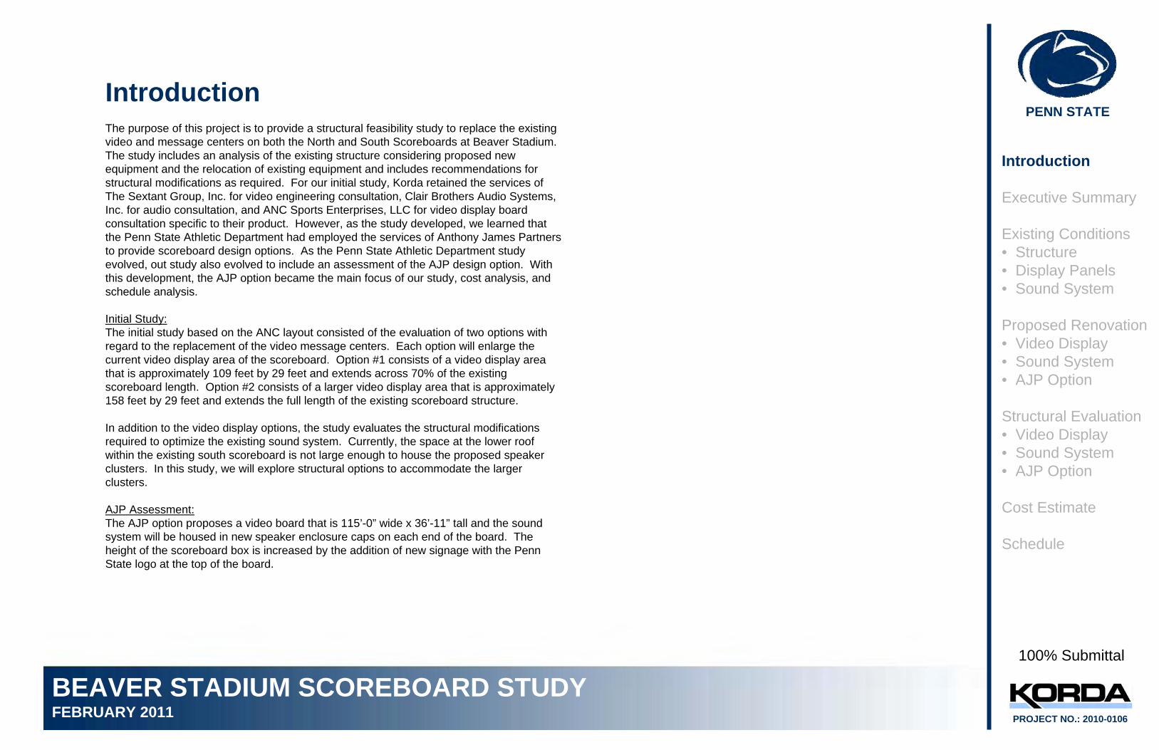
IntroductionThe purpose of this project is to provide a structural feasibility study to replace the existing video and message centers on both the North and South Scoreboards at Beaver Stadium. The study includes an analysis of the existing structure considering proposed new equipment and the relocation of existing equipment and includes recommendations for structural modifications as required. For our initial study, Korda retained the services of The Sextant Group, Inc. for video engineering consultation, Clair Brothers Audio Systems, Inc. for audio consultation, and ANC Sports Enterprises, LLC for video display board consultation specific to their product. However, as the study developed, we learned that the Penn State Athletic Department had employed the services of Anthony James Partners to provide scoreboard design options. As the Penn State Athletic Department study evolved, out study also evolved to include an assessment of the AJP design option. With this development, the AJP option became the main focus of our study, cost analysis, and schedule analysis.
Initial Study:The initial study based on the ANC layout consisted of the evaluation of two options with regard to the replacement of the video message centers. Each option will enlarge the current video display area of the scoreboard. Option #1 consists of a video display area that is approximately 109 feet by 29 feet and extends across 70% of the existing scoreboard length. Option #2 consists of a larger video display area that is approximately 158 feet by 29 feet and extends the full length of the existing scoreboard structure.
In addition to the video display options, the study evaluates the structural modifications required to optimize the existing sound system. Currently, the space at the lower roof within the existing south scoreboard is not large enough to house the proposed speaker clusters. In this study, we will explore structural options to accommodate the larger clusters.
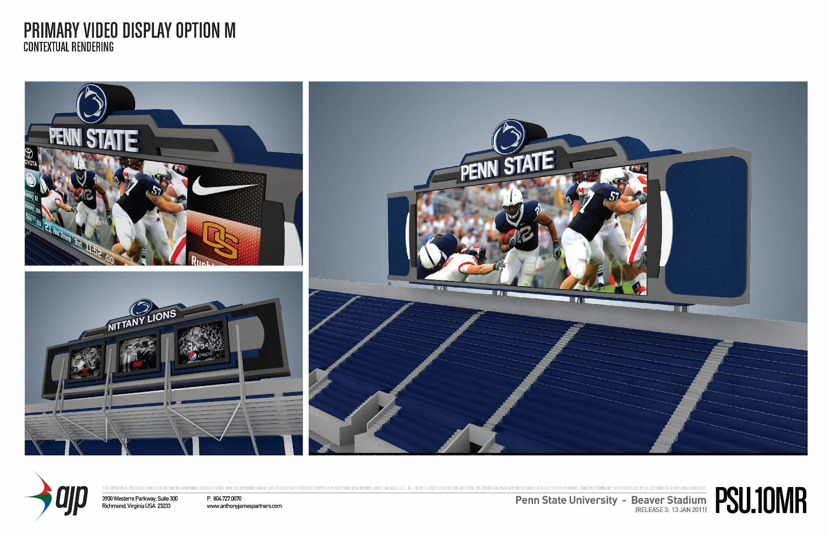
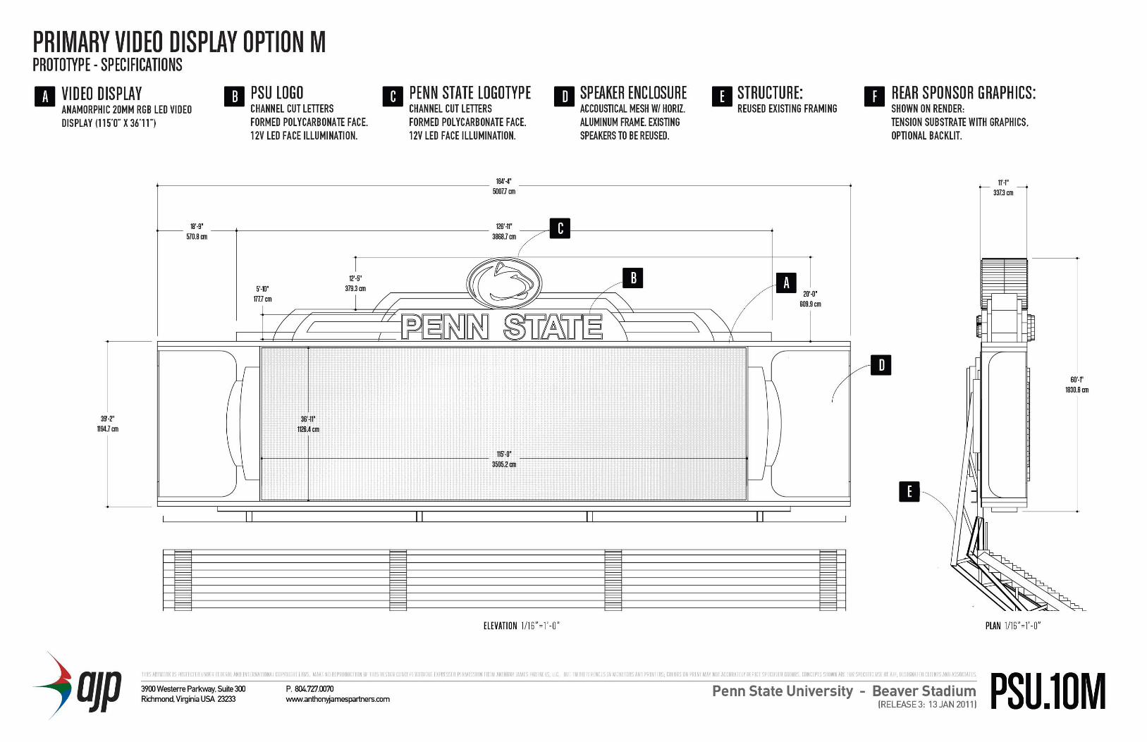
AJP Assessment:The AJP option proposes a video board that is 115’-0” wide x 36’-11” tall and the sound system will be housed in new speaker enclosure caps on each end of the board. The height of the scoreboard box is increased by the addition of new signage with the Penn State logo at the top of the board.
Introduction
Executive Summary
Existing Conditions• Structure• Display Panels• Sound System
Proposed Renovation• Video Display• Sound System• AJP Option
Structural Evaluation• Video Display• Sound System• AJP Option
Cost Estimate
Schedule
100% Submittal
PENN STATE
BEAVER STADIUM SCOREBOARD STUDYFEBRUARY 2011 PROJECT NO.: 2010-0106
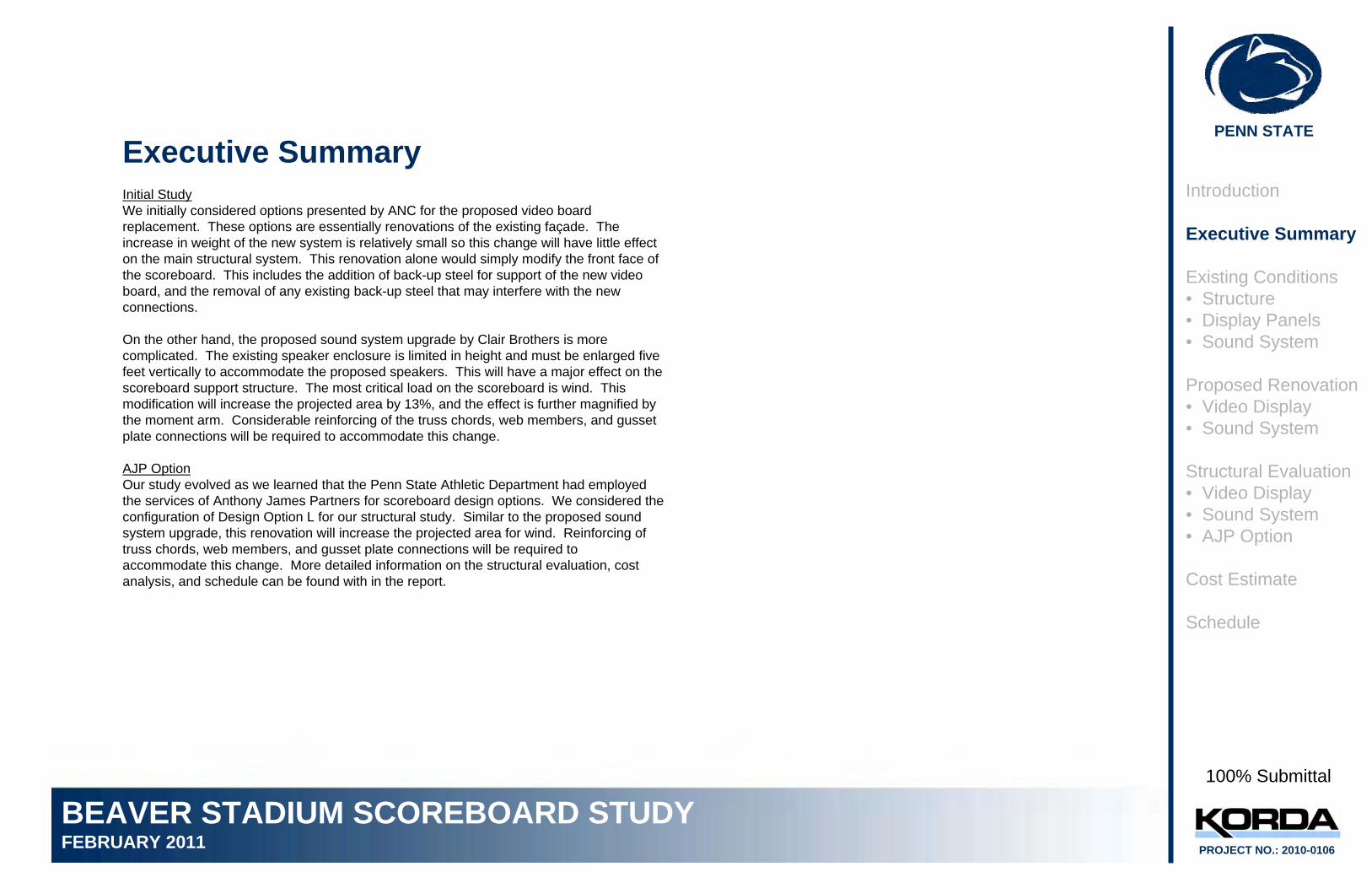
Executive SummaryInitial StudyWe initially considered options presented by ANC for the proposed video board replacement. These options are essentially renovations of the existing façade. The increase in weight of the new system is relatively small so this change will have little effect on the main structural system. This renovation alone would simply modify the front face of the scoreboard. This includes the addition of back-up steel for support of the new video board, and the removal of any existing back-up steel that may interfere with the new connections.
On the other hand, the proposed sound system upgrade by Clair Brothers is more complicated. The existing speaker enclosure is limited in height and must be enlarged five feet vertically to accommodate the proposed speakers. This will have a major effect on the scoreboard support structure. The most critical load on the scoreboard is wind. This modification will increase the projected area by 13%, and the effect is further magnified by the moment arm. Considerable reinforcing of the truss chords, web members, and gusset plate connections will be required to accommodate this change.
AJP OptionOur study evolved as we learned that the Penn State Athletic Department had employed the services of Anthony James Partners for scoreboard design options. We considered the configuration of Design Option L for our structural study. Similar to the proposed sound system upgrade, this renovation will increase the projected area for wind. Reinforcing of truss chords, web members, and gusset plate connections will be required to accommodate this change. More detailed information on the structural evaluation, cost analysis, and schedule can be found with in the report.
Introduction
Executive Summary
Existing Conditions• Structure• Display Panels• Sound System
Proposed Renovation• Video Display• Sound System
Structural Evaluation• Video Display• Sound System• AJP Option
Cost Estimate
Schedule
100% Submittal
PENN STATE
BEAVER STADIUM SCOREBOARD STUDYFEBRUARY 2011 PROJECT NO.: 2010-0106
Existing ConditionsThe existing scoreboards were designed as part of the 2000 Beaver Stadium Expansion and Renovation project. Each scoreboard is 158’-4” wide by 38’-1” tall with three interior catwalk levels and a lower and upper roof level. Both scoreboards house video display systems for the stadium and the south scoreboard houses the stadium’s audio system with a speaker grille at the lower roof.
Introduction
Executive Summary
Existing Conditions• Structure• Display Panels• Sound System
Proposed Renovation• Video Display• Sound System
Structural Evaluation• Video Display• Sound System• AJP Option
Cost Estimate
Schedule
Existing StructureFor the purposes of our study, we referenced the following structural documents:• The 2000 Stadium Renovation drawings by HOK and Thornton Tomasetti• The 2000 north scoreboard shop drawings by Powell Steel Corporation• The 2001 south scoreboard shop drawings by Stewart Amos Steel, Inc.
North Scoreboard Structure
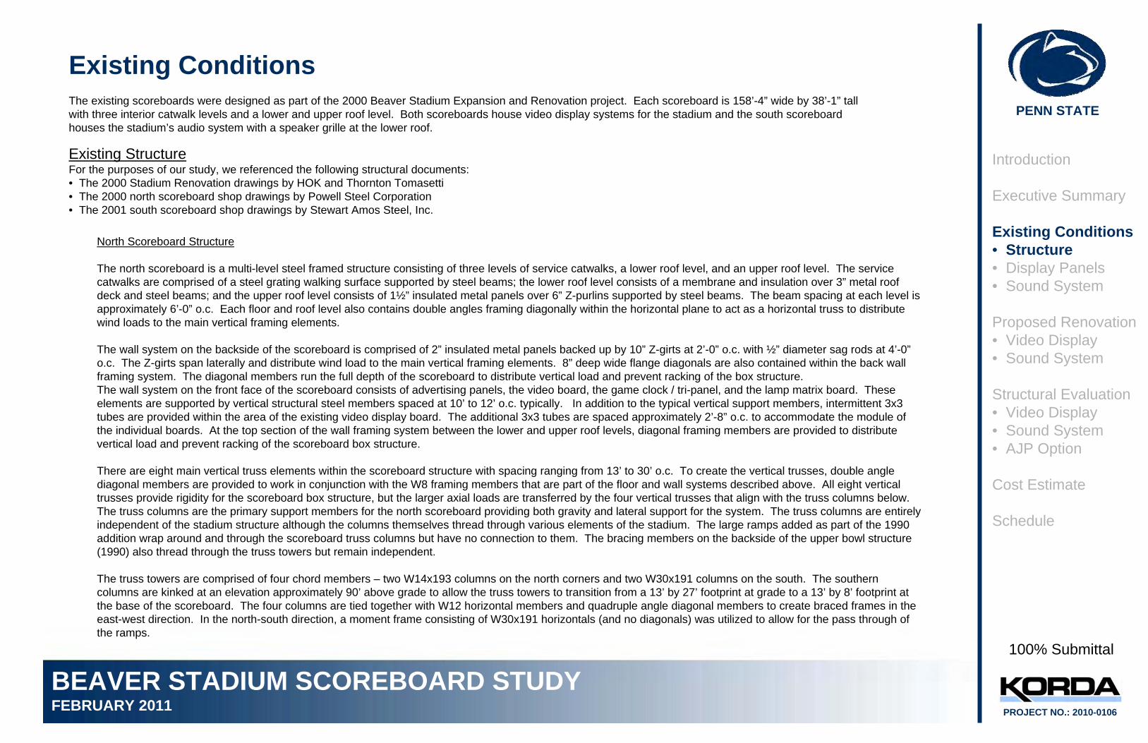
The north scoreboard is a multi-level steel framed structure consisting of three levels of service catwalks, a lower roof level, and an upper roof level. The service catwalks are comprised of a steel grating walking surface supported by steel beams; the lower roof level consists of a membrane and insulation over 3” metal roof deck and steel beams; and the upper roof level consists of 1½” insulated metal panels over 6” Z-purlins supported by steel beams. The beam spacing at each level is approximately 6’-0” o.c. Each floor and roof level also contains double angles framing diagonally within the horizontal plane to act as a horizontal truss to distribute wind loads to the main vertical framing elements.
The wall system on the backside of the scoreboard is comprised of 2” insulated metal panels backed up by 10” Z-girts at 2’-0” o.c. with ½” diameter sag rods at 4’-0”o.c. The Z-girts span laterally and distribute wind load to the main vertical framing elements. 8” deep wide flange diagonals are also contained within the back wall framing system. The diagonal members run the full depth of the scoreboard to distribute vertical load and prevent racking of the box structure.The wall system on the front face of the scoreboard consists of advertising panels, the video board, the game clock / tri-panel, and the lamp matrix board. These elements are supported by vertical structural steel members spaced at 10’ to 12’ o.c. typically. In addition to the typical vertical support members, intermittent 3x3 tubes are provided within the area of the existing video display board. The additional 3x3 tubes are spaced approximately 2’-8” o.c. to accommodate the module of the individual boards. At the top section of the wall framing system between the lower and upper roof levels, diagonal framing members are provided to distribute vertical load and prevent racking of the scoreboard box structure.
There are eight main vertical truss elements within the scoreboard structure with spacing ranging from 13’ to 30’ o.c. To create the vertical trusses, double angle diagonal members are provided to work in conjunction with the W8 framing members that are part of the floor and wall systems described above. All eight vertical trusses provide rigidity for the scoreboard box structure, but the larger axial loads are transferred by the four vertical trusses that align with the truss columns below.The truss columns are the primary support members for the north scoreboard providing both gravity and lateral support for the system. The truss columns are entirely independent of the stadium structure although the columns themselves thread through various elements of the stadium. The large ramps added as part of the 1990 addition wrap around and through the scoreboard truss columns but have no connection to them. The bracing members on the backside of the upper bowl structure (1990) also thread through the truss towers but remain independent.
The truss towers are comprised of four chord members – two W14x193 columns on the north corners and two W30x191 columns on the south. The southern columns are kinked at an elevation approximately 90’ above grade to allow the truss towers to transition from a 13’ by 27’ footprint at grade to a 13’ by 8’ footprint at the base of the scoreboard. The four columns are tied together with W12 horizontal members and quadruple angle diagonal members to create braced frames in the east-west direction. In the north-south direction, a moment frame consisting of W30x191 horizontals (and no diagonals) was utilized to allow for the pass through of the ramps.
100% Submittal
PENN STATE
BEAVER STADIUM SCOREBOARD STUDYFEBRUARY 2011 PROJECT NO.: 2010-0106
Existing North Scoreboard Structure
Front Elevation Side View
Truss Towers
Vertical Truss Elements(Typ. of 8) Moment Frame
@ Truss Towers for Passage of Ramps
Catwalk Levels Introduction
Executive Summary
Existing Conditions• Structure• Display Panels• Sound System
Proposed Renovation• Video Display• Sound System
Structural Evaluation• Video Display• Sound System• AJP Option
Cost Estimate
Schedule
100% Submittal
PENN STATE
BEAVER STADIUM SCOREBOARD STUDYFEBRUARY 2011 PROJECT NO.: 2010-0106
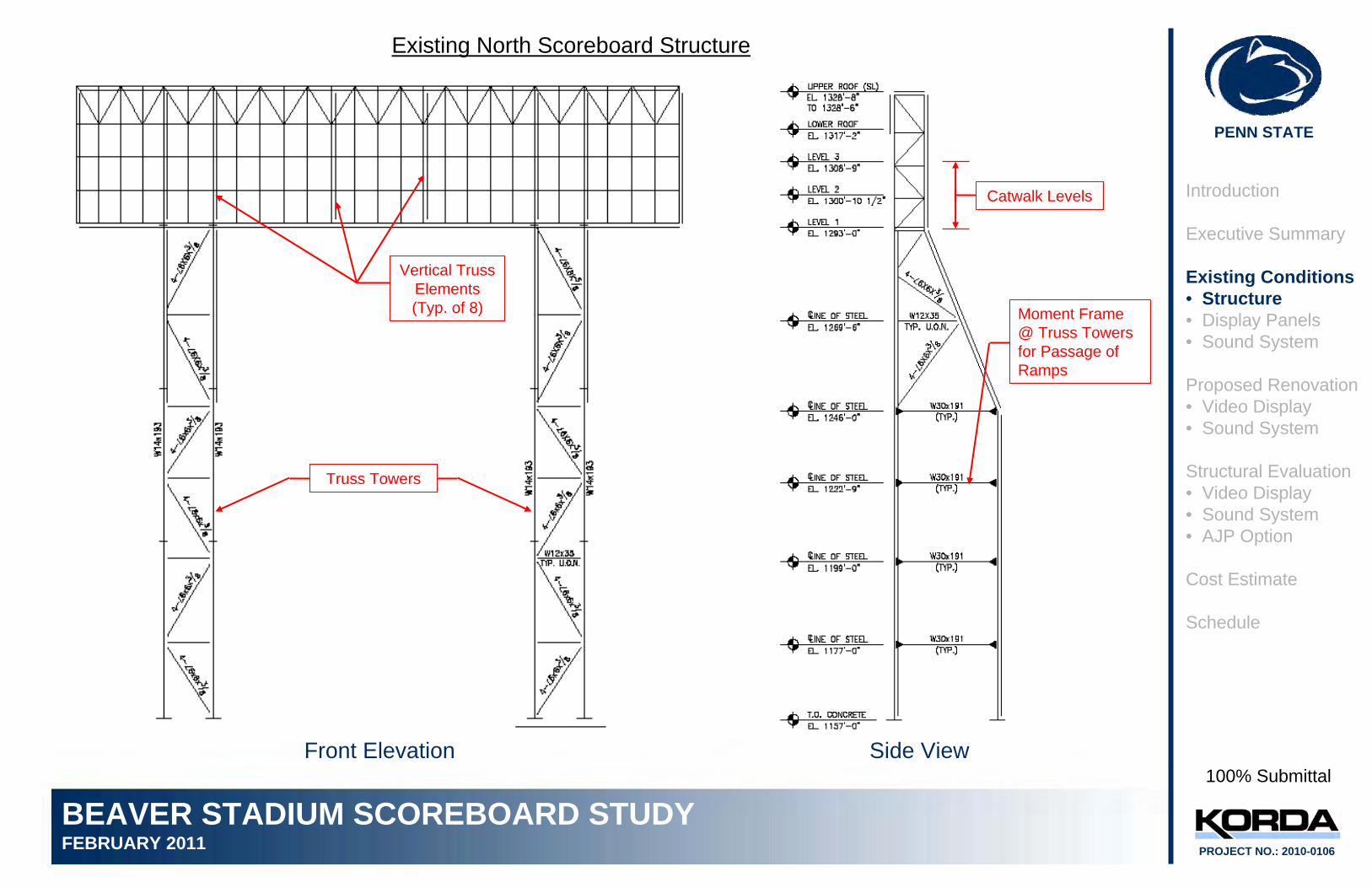
Existing North Scoreboard Structure
Scoreboard Erection Northwest View
Introduction
Executive Summary
Existing Conditions• Structure• Display Panels• Sound System
Proposed Renovation• Video Display• Sound System
Structural Evaluation• Video Display• Sound System• AJP Option
Cost Estimate
Schedule
100% Submittal
PENN STATE
BEAVER STADIUM SCOREBOARD STUDYFEBRUARY 2011 PROJECT NO.: 2010-0106
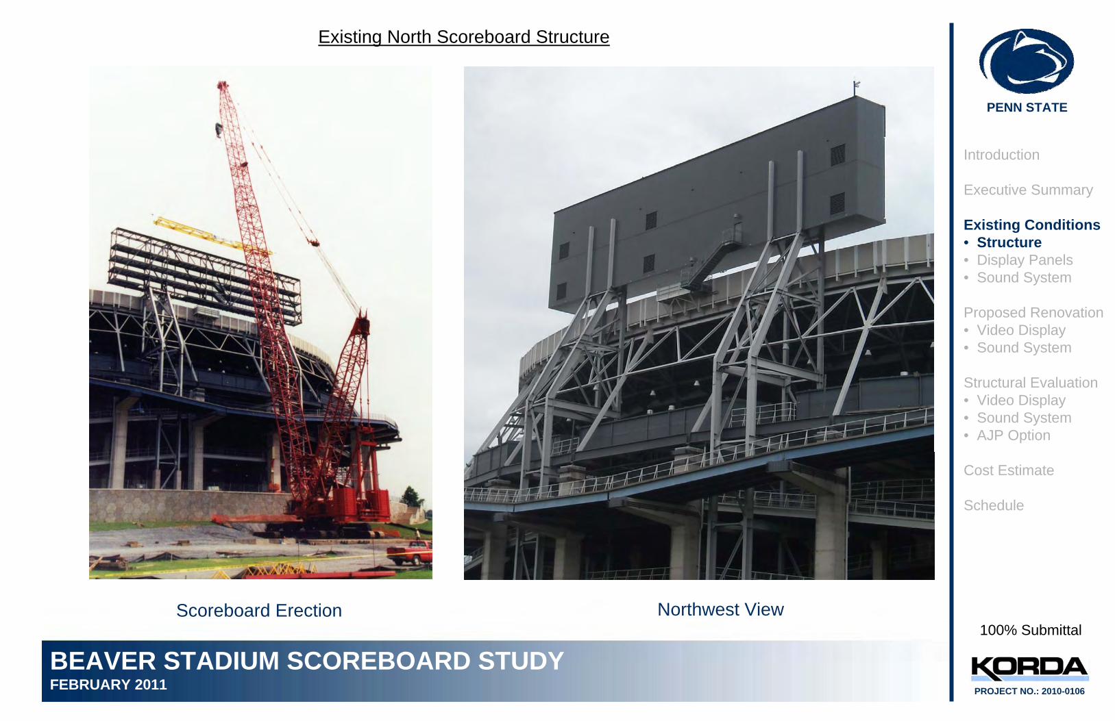
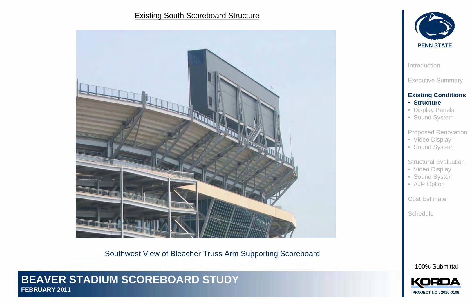
Existing South Scoreboard Structure
The framing for the south scoreboard box structure is very similar to that previously described for the north scoreboard structure. However, the vertical truss quantity and spacing is different because the method of primary support of the box structure is entirely different.
Unlike the north scoreboard, the south scoreboard is not independent of the stadium structure. The primary supports for the scoreboard are arms that extend from four of the main trusses that carry the upper level of seating. The trusses are spaced at 42’-4” o.c. The main vertical elements within the box structure align with these trusses and two additional vertical elements are provided at each end of the box structure.
Bleacher Truss Arm for Scoreboard Support Scoreboard Section
Introduction
Executive Summary
Existing Conditions• Structure• Display Panels• Sound System
Proposed Renovation• Video Display• Sound System
Structural Evaluation• Video Display• Sound System• AJP Option
Cost Estimate
Schedule
100% Submittal
PENN STATE
BEAVER STADIUM SCOREBOARD STUDYFEBRUARY 2011 PROJECT NO.: 2010-0106
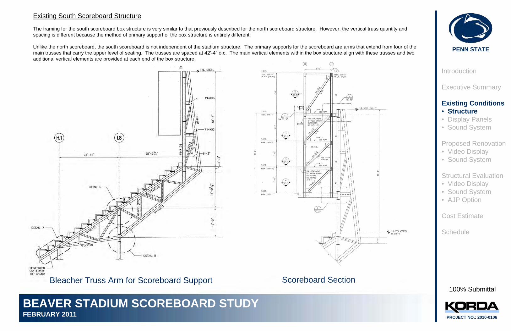
Existing South Scoreboard Structure
Southwest View of Bleacher Truss Arm Supporting Scoreboard
Introduction
Executive Summary
Existing Conditions• Structure• Display Panels• Sound System
Proposed Renovation• Video Display• Sound System
Structural Evaluation• Video Display• Sound System• AJP Option
Cost Estimate
Schedule
100% Submittal
PENN STATE
BEAVER STADIUM SCOREBOARD STUDYFEBRUARY 2011 PROJECT NO.: 2010-0106
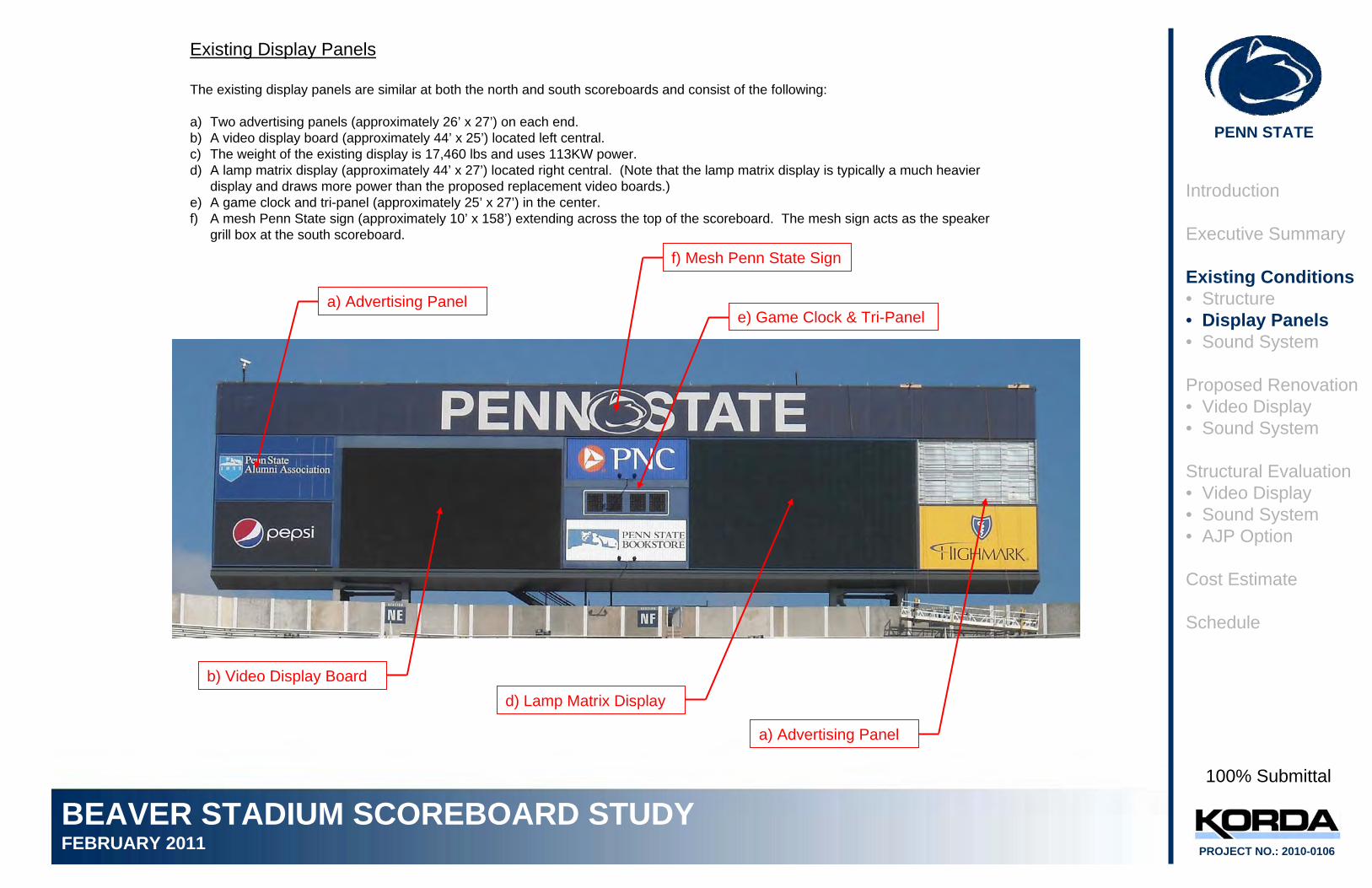
Existing Display Panels
The existing display panels are similar at both the north and south scoreboards and consist of the following:
a) Two advertising panels (approximately 26’ x 27’) on each end.b) A video display board (approximately 44’ x 25’) located left central.c) The weight of the existing display is 17,460 lbs and uses 113KW power.d) A lamp matrix display (approximately 44’ x 27’) located right central. (Note that the lamp matrix display is typically a much heavier
display and draws more power than the proposed replacement video boards.)e) A game clock and tri-panel (approximately 25’ x 27’) in the center.f) A mesh Penn State sign (approximately 10’ x 158’) extending across the top of the scoreboard. The mesh sign acts as the speaker
grill box at the south scoreboard.
b) Video Display Board
d) Lamp Matrix Display
e) Game Clock & Tri-Panela) Advertising Panel
a) Advertising Panel
f) Mesh Penn State Sign
Introduction
Executive Summary
Existing Conditions• Structure• Display Panels• Sound System
Proposed Renovation• Video Display• Sound System
Structural Evaluation• Video Display• Sound System• AJP Option
Cost Estimate
Schedule
100% Submittal
PENN STATE
BEAVER STADIUM SCOREBOARD STUDYFEBRUARY 2011 PROJECT NO.: 2010-0106
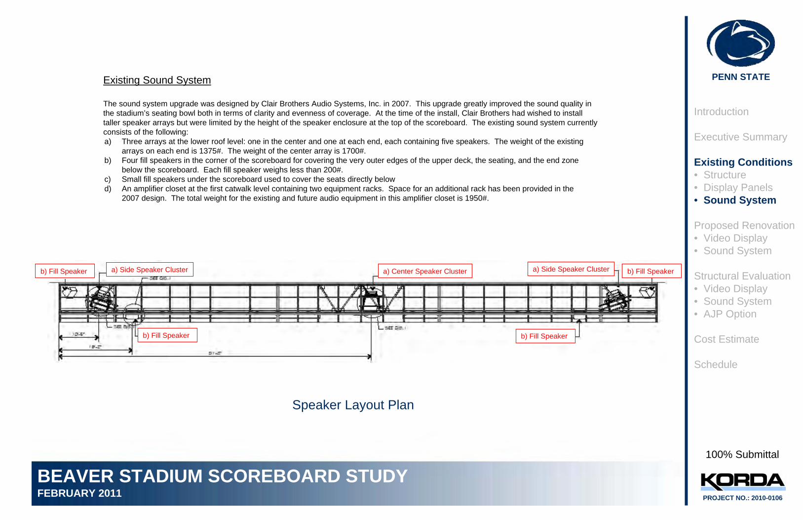
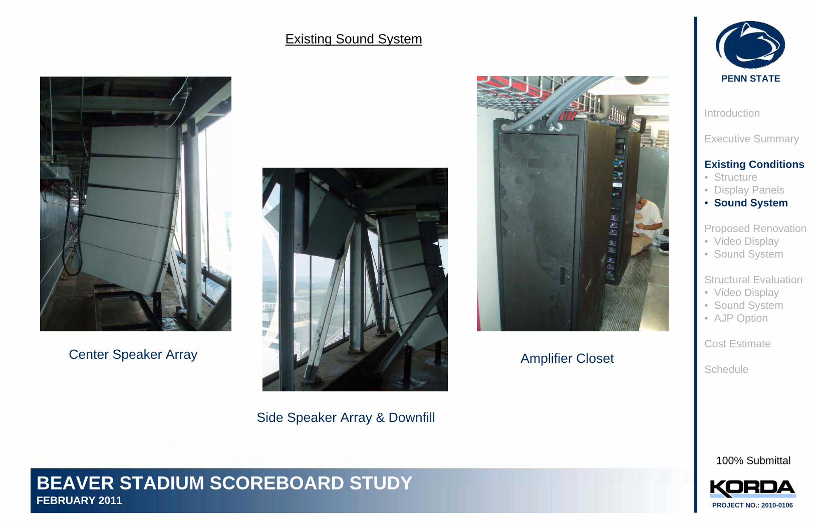
Existing Sound System
The sound system upgrade was designed by Clair Brothers Audio Systems, Inc. in 2007. This upgrade greatly improved the sound quality in the stadium’s seating bowl both in terms of clarity and evenness of coverage. At the time of the install, Clair Brothers had wished to install taller speaker arrays but were limited by the height of the speaker enclosure at the top of the scoreboard. The existing sound system currently consists of the following:
a) Side Speaker Cluster
b) Fill Speaker b) Fill Speaker
b) Fill Speakera) Side Speaker Clustera) Center Speaker Clusterb) Fill Speaker
Speaker Layout Plan
a) Three arrays at the lower roof level: one in the center and one at each end, each containing five speakers. The weight of the existing arrays on each end is 1375#. The weight of the center array is 1700#.
b) Four fill speakers in the corner of the scoreboard for covering the very outer edges of the upper deck, the seating, and the end zone below the scoreboard. Each fill speaker weighs less than 200#.
c) Small fill speakers under the scoreboard used to cover the seats directly belowd) An amplifier closet at the first catwalk level containing two equipment racks. Space for an additional rack has been provided in the
2007 design. The total weight for the existing and future audio equipment in this amplifier closet is 1950#.
Introduction
Executive Summary
Existing Conditions• Structure• Display Panels• Sound System
Proposed Renovation• Video Display• Sound System
Structural Evaluation• Video Display• Sound System• AJP Option
Cost Estimate
Schedule
100% Submittal
PENN STATE
BEAVER STADIUM SCOREBOARD STUDYFEBRUARY 2011 PROJECT NO.: 2010-0106
Existing Sound System
Center Speaker Array
Side Speaker Array & Downfill
Amplifier Closet
Introduction
Executive Summary
Existing Conditions• Structure• Display Panels• Sound System
Proposed Renovation• Video Display• Sound System
Structural Evaluation• Video Display• Sound System• AJP Option
Cost Estimate
Schedule
100% Submittal
PENN STATE
BEAVER STADIUM SCOREBOARD STUDYFEBRUARY 2011 PROJECT NO.: 2010-0106
Proposed Renovation – ANC (Initial Study)
Video Display Board Replacement
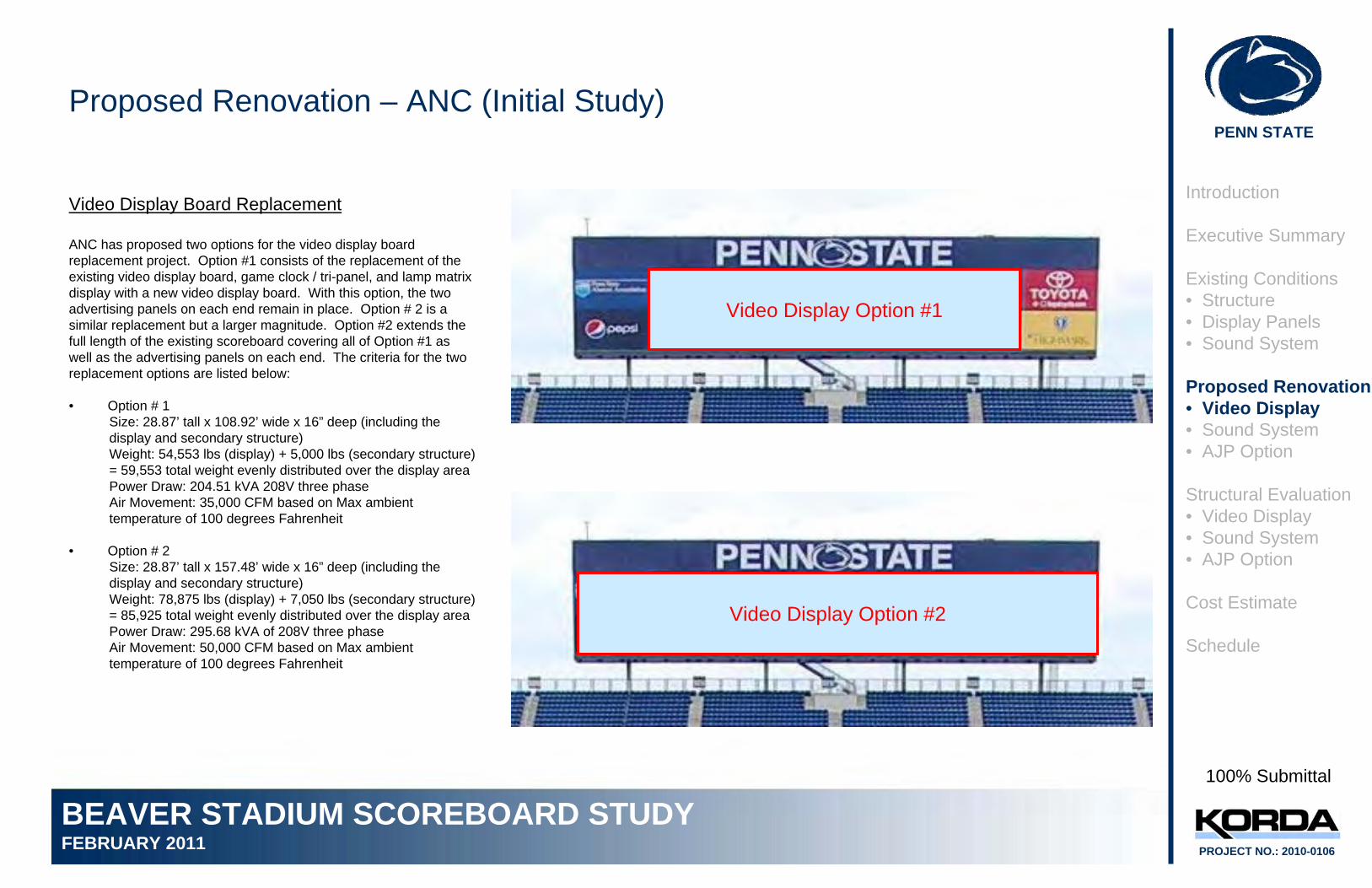
ANC has proposed two options for the video display board replacement project. Option #1 consists of the replacement of the existing video display board, game clock / tri-panel, and lamp matrix display with a new video display board. With this option, the two advertising panels on each end remain in place. Option # 2 is asimilar replacement but a larger magnitude. Option #2 extends the full length of the existing scoreboard covering all of Option #1 as well as the advertising panels on each end. The criteria for the two replacement options are listed below:
• Option # 1 Size: 28.87’ tall x 108.92’ wide x 16” deep (including the display and secondary structure)Weight: 54,553 lbs (display) + 5,000 lbs (secondary structure) = 59,553 total weight evenly distributed over the display areaPower Draw: 204.51 kVA 208V three phaseAir Movement: 35,000 CFM based on Max ambient temperature of 100 degrees Fahrenheit
• Option # 2Size: 28.87’ tall x 157.48’ wide x 16” deep (including the display and secondary structure)Weight: 78,875 lbs (display) + 7,050 lbs (secondary structure) = 85,925 total weight evenly distributed over the display areaPower Draw: 295.68 kVA of 208V three phaseAir Movement: 50,000 CFM based on Max ambient temperature of 100 degrees Fahrenheit
Video Display Option #1
Video Display Option #2
Introduction
Executive Summary
Existing Conditions• Structure• Display Panels• Sound System
Proposed Renovation• Video Display• Sound System• AJP Option
Structural Evaluation• Video Display• Sound System• AJP Option
Cost Estimate
Schedule
100% Submittal
PENN STATE
BEAVER STADIUM SCOREBOARD STUDYFEBRUARY 2011 PROJECT NO.: 2010-0106
Proposed Renovation – Clair Brothers (Initial Study)
Sound System Upgrade
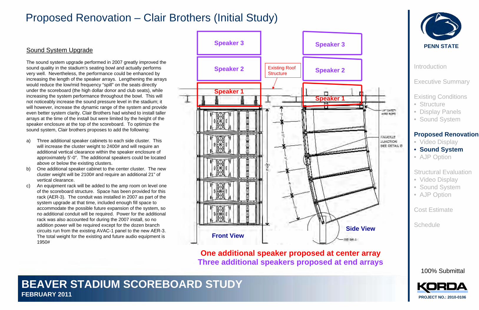
The sound system upgrade performed in 2007 greatly improved the sound quality in the stadium’s seating bowl and actually performs very well. Nevertheless, the performance could be enhanced by increasing the length of the speaker arrays. Lengthening the arrays would reduce the low/mid frequency “spill” on the seats directly under the scoreboard (the high dollar donor and club seats), while increasing the system performance throughout the bowl. This will not noticeably increase the sound pressure level in the stadium; it will however, increase the dynamic range of the system and provide even better system clarity. Clair Brothers had wished to install taller arrays at the time of the install but were limited by the height of the speaker enclosure at the top of the scoreboard. To optimize thesound system, Clair brothers proposes to add the following:
One additional speaker proposed at center arrayThree additional speakers proposed at end arrays
Existing Roof Structure
a) Three additional speaker cabinets to each side cluster. This will increase the cluster weight to 2400# and will require an additional vertical clearance within the speaker enclosure of approximately 5’-0”. The additional speakers could be located above or below the existing clusters.
b) One additional speaker cabinet to the center cluster. The new cluster weight will be 2100# and require an additional 21” of vertical clearance.
c) An equipment rack will be added to the amp room on level one of the scoreboard structure. Space has been provided for this rack (AER-3). The conduit was installed in 2007 as part of the system upgrade at that time, included enough fill space to accommodate the possible future expansion of the system, so no additional conduit will be required. Power for the additional rack was also accounted for during the 2007 install, so no addition power will be required except for the dozen branch circuits run from the existing AVAC-1 panel to the new AER-3. The total weight for the existing and future audio equipment is 1950#
Front ViewSide View
Speaker 1
Speaker 2
Speaker 3
Speaker 1
Speaker 2
Speaker 3
Introduction
Executive Summary
Existing Conditions• Structure• Display Panels• Sound System
Proposed Renovation• Video Display• Sound System• AJP Option
Structural Evaluation• Video Display• Sound System• AJP Option
Cost Estimate
Schedule
100% Submittal
PENN STATE
BEAVER STADIUM SCOREBOARD STUDYFEBRUARY 2011 PROJECT NO.: 2010-0106
Introduction
Executive Summary
Existing Conditions• Structure• Display Panels• Sound System
Proposed Renovation• Video Display• Sound System• AJP Option
Structural Evaluation• Video Display• Sound System• AJP Option
Cost Estimate
Schedule
100% Submittal
Proposed Renovation - AJP
AJP Option
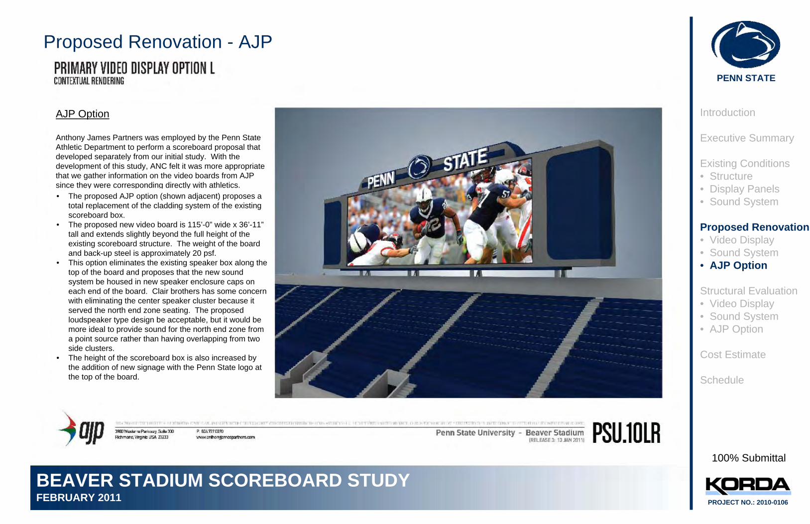
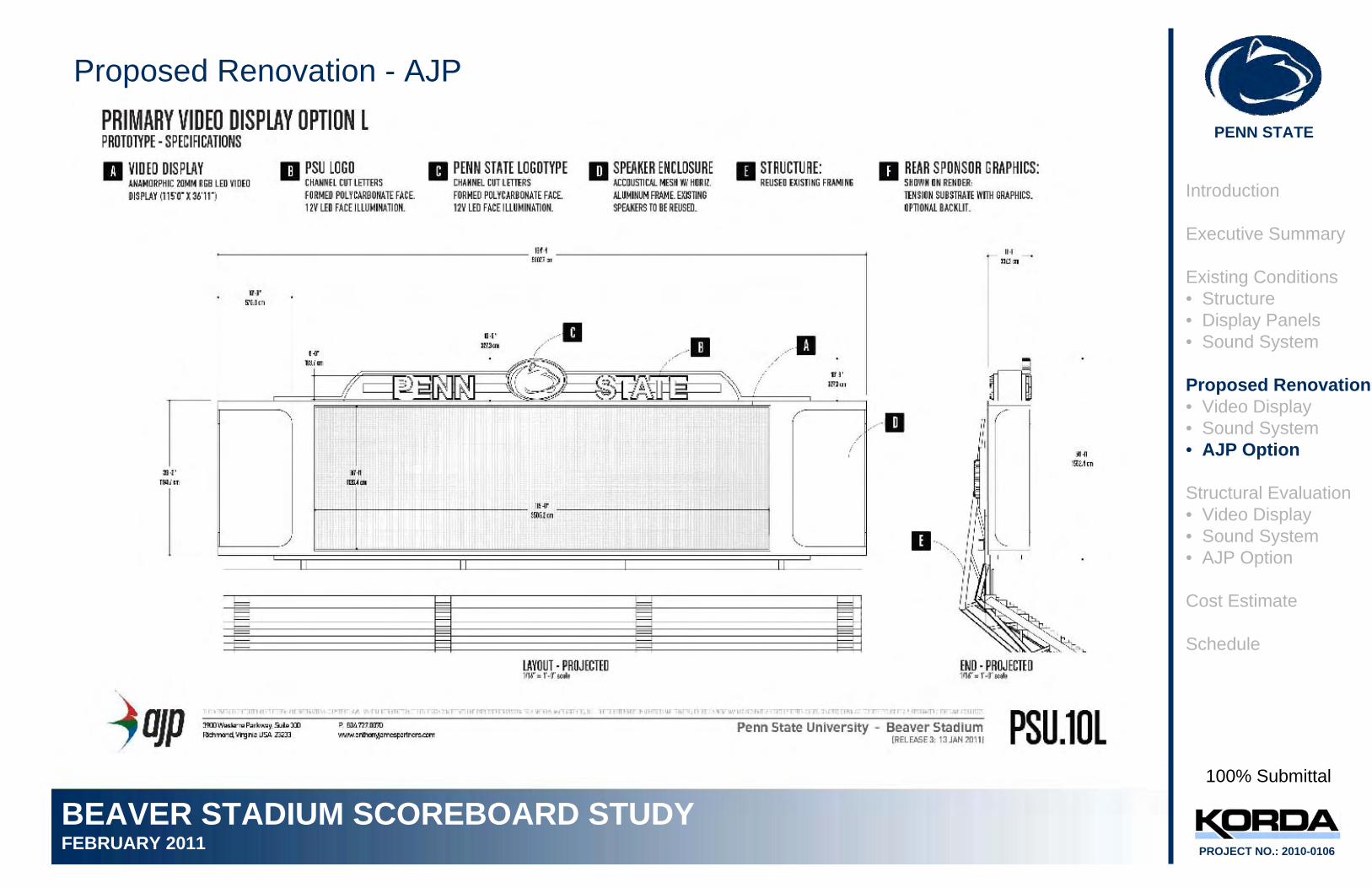
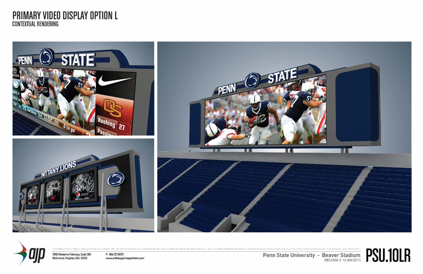
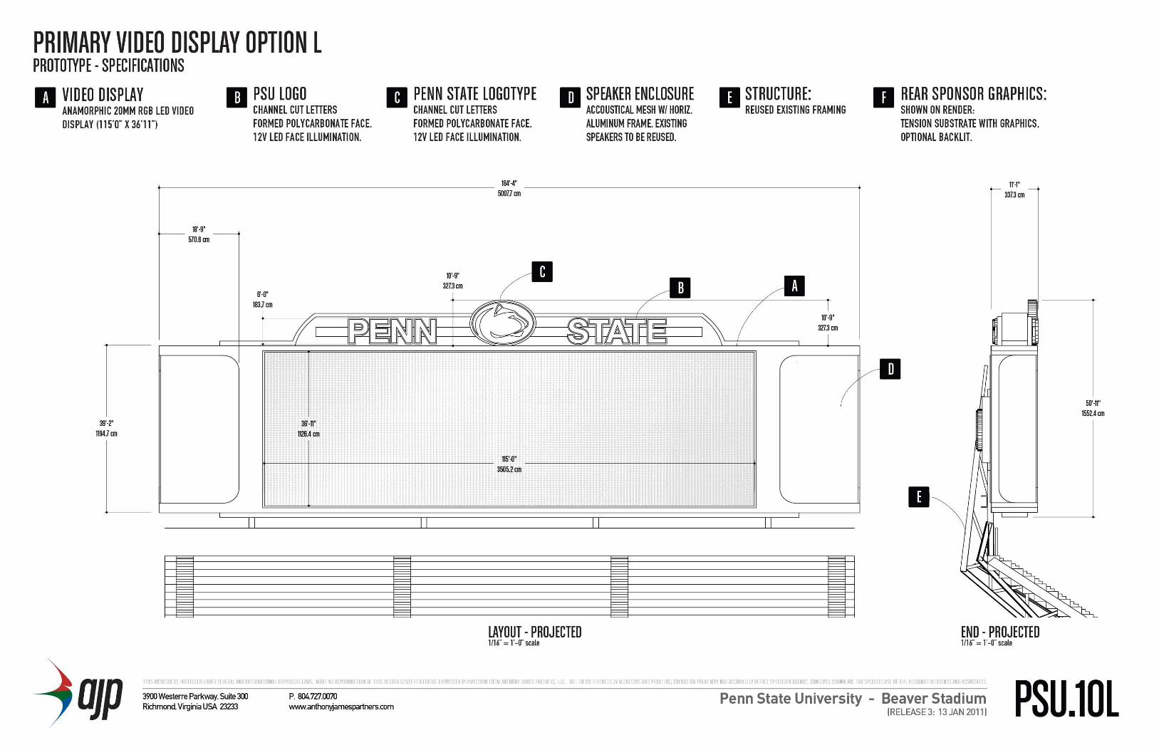
Anthony James Partners was employed by the Penn State Athletic Department to perform a scoreboard proposal that developed separately from our initial study. With the development of this study, ANC felt it was more appropriate that we gather information on the video boards from AJP since they were corresponding directly with athletics.• The proposed AJP option (shown adjacent) proposes a
total replacement of the cladding system of the existing scoreboard box.
• The proposed new video board is 115’-0” wide x 36’-11”tall and extends slightly beyond the full height of the existing scoreboard structure. The weight of the board and back-up steel is approximately 20 psf.
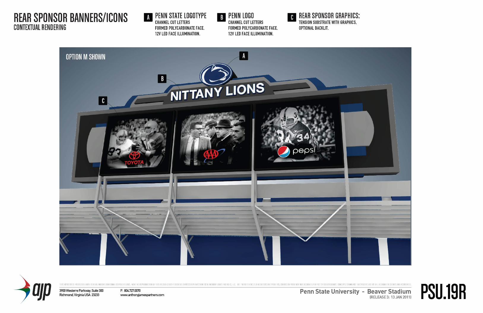
• This option eliminates the existing speaker box along the top of the board and proposes that the new sound system be housed in new speaker enclosure caps on each end of the board. Clair brothers has some concern with eliminating the center speaker cluster because it served the north end zone seating. The proposed loudspeaker type design be acceptable, but it would be more ideal to provide sound for the north end zone from a point source rather than having overlapping from two side clusters.
• The height of the scoreboard box is also increased by the addition of new signage with the Penn State logo at the top of the board.
PENN STATE
BEAVER STADIUM SCOREBOARD STUDYFEBRUARY 2011 PROJECT NO.: 2010-0106
Introduction
Executive Summary
Existing Conditions• Structure• Display Panels• Sound System
Proposed Renovation• Video Display• Sound System• AJP Option
Structural Evaluation• Video Display• Sound System• AJP Option
Cost Estimate
Schedule
100% Submittal
Proposed Renovation - AJP
PENN STATE
BEAVER STADIUM SCOREBOARD STUDYFEBRUARY 2011 PROJECT NO.: 2010-0106
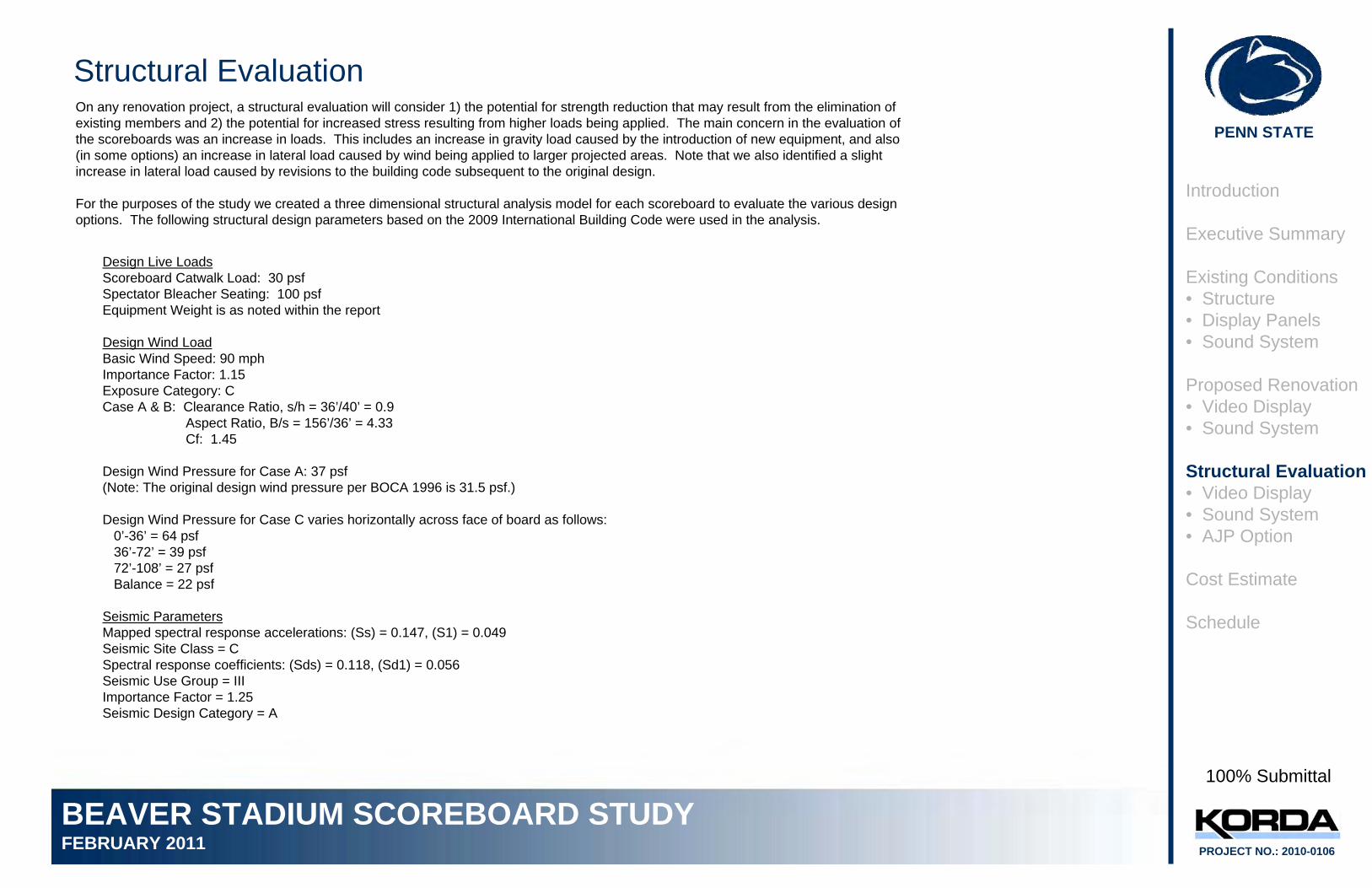
Structural EvaluationOn any renovation project, a structural evaluation will consider 1) the potential for strength reduction that may result from the elimination of existing members and 2) the potential for increased stress resulting from higher loads being applied. The main concern in the evaluation of the scoreboards was an increase in loads. This includes an increase in gravity load caused by the introduction of new equipment, and also (in some options) an increase in lateral load caused by wind being applied to larger projected areas. Note that we also identified a slight increase in lateral load caused by revisions to the building code subsequent to the original design.
For the purposes of the study we created a three dimensional structural analysis model for each scoreboard to evaluate the various design options. The following structural design parameters based on the 2009 International Building Code were used in the analysis.
Design Live LoadsScoreboard Catwalk Load: 30 psfSpectator Bleacher Seating: 100 psfEquipment Weight is as noted within the report
Design Wind LoadBasic Wind Speed: 90 mphImportance Factor: 1.15Exposure Category: CCase A & B: Clearance Ratio, s/h = 36’/40’ = 0.9
Aspect Ratio, B/s = 156’/36’ = 4.33Cf: 1.45
Design Wind Pressure for Case A: 37 psf(Note: The original design wind pressure per BOCA 1996 is 31.5 psf.)
Design Wind Pressure for Case C varies horizontally across face of board as follows:0’-36’ = 64 psf36’-72’ = 39 psf72’-108’ = 27 psfBalance = 22 psf
Seismic ParametersMapped spectral response accelerations: (Ss) = 0.147, (S1) = 0.049Seismic Site Class = CSpectral response coefficients: (Sds) = 0.118, (Sd1) = 0.056Seismic Use Group = IIIImportance Factor = 1.25Seismic Design Category = A
Introduction
Executive Summary
Existing Conditions• Structure• Display Panels• Sound System
Proposed Renovation• Video Display• Sound System
Structural Evaluation• Video Display• Sound System• AJP Option
Cost Estimate
Schedule
100% Submittal
PENN STATE
BEAVER STADIUM SCOREBOARD STUDYFEBRUARY 2011 PROJECT NO.: 2010-0106
Introduction
Executive Summary
Existing Conditions• Structure• Display Panels• Sound System
Proposed Renovation• Video Display• Sound System
Structural Evaluation• Video Display• Sound System• AJP Option
Cost Estimate
Schedule
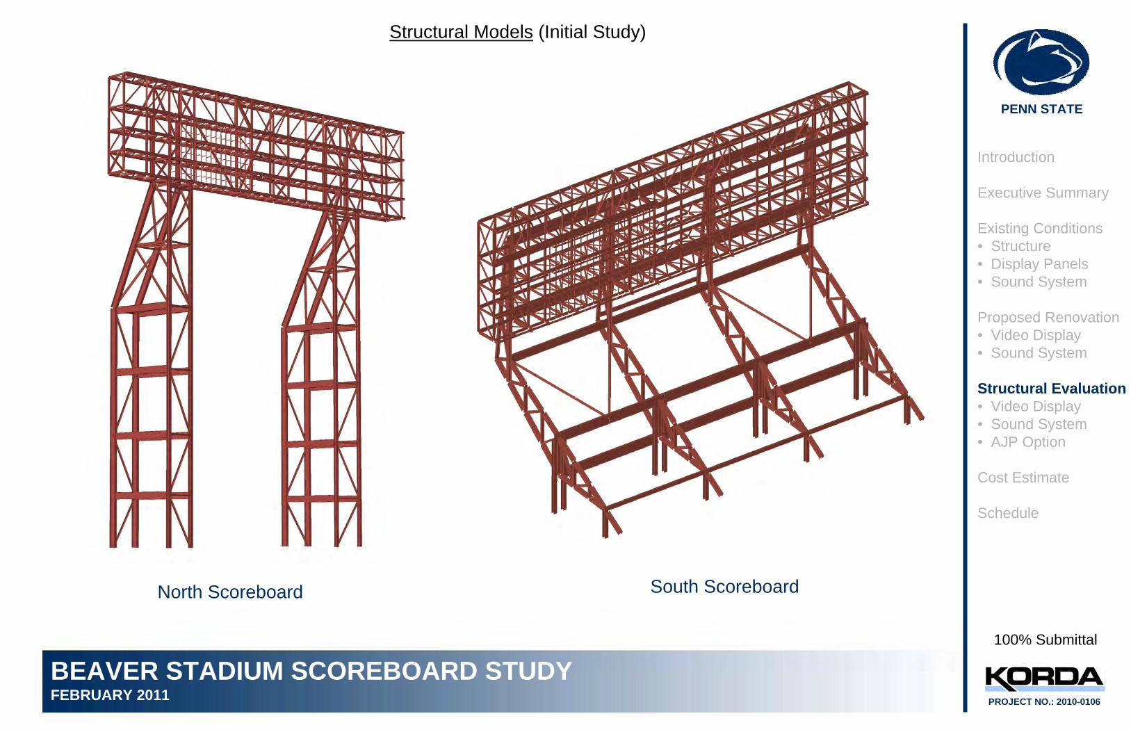
Structural Models (Initial Study)
North Scoreboard South Scoreboard
100% Submittal
PENN STATE
BEAVER STADIUM SCOREBOARD STUDYFEBRUARY 2011 PROJECT NO.: 2010-0106
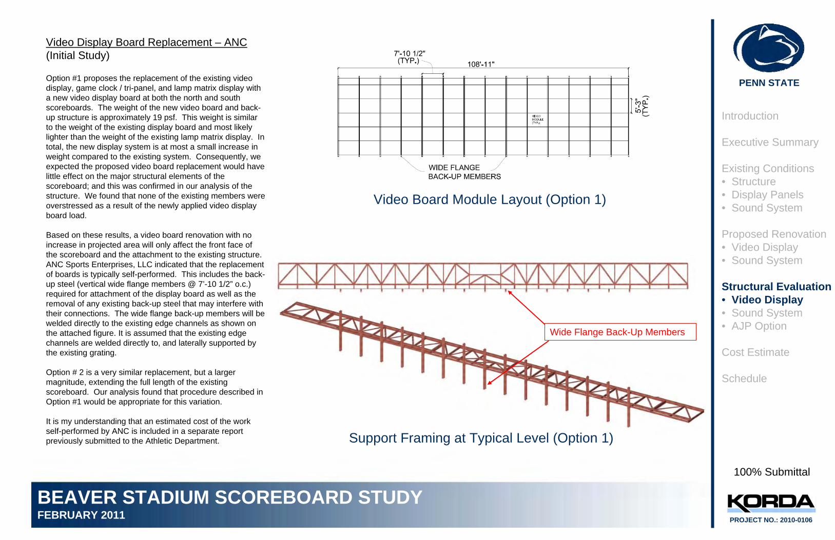
Video Display Board Replacement – ANC(Initial Study)
Option #1 proposes the replacement of the existing video display, game clock / tri-panel, and lamp matrix display with a new video display board at both the north and south scoreboards. The weight of the new video board and back-up structure is approximately 19 psf. This weight is similar to the weight of the existing display board and most likely lighter than the weight of the existing lamp matrix display. Intotal, the new display system is at most a small increase in weight compared to the existing system. Consequently, we expected the proposed video board replacement would have little effect on the major structural elements of the scoreboard; and this was confirmed in our analysis of the structure. We found that none of the existing members were overstressed as a result of the newly applied video display board load.
Based on these results, a video board renovation with no increase in projected area will only affect the front face of the scoreboard and the attachment to the existing structure. ANC Sports Enterprises, LLC indicated that the replacement of boards is typically self-performed. This includes the back-up steel (vertical wide flange members @ 7’-10 1/2” o.c.) required for attachment of the display board as well as the removal of any existing back-up steel that may interfere with their connections. The wide flange back-up members will be welded directly to the existing edge channels as shown on the attached figure. It is assumed that the existing edge channels are welded directly to, and laterally supported by the existing grating.
Option # 2 is a very similar replacement, but a larger magnitude, extending the full length of the existing scoreboard. Our analysis found that procedure described in Option #1 would be appropriate for this variation.
It is my understanding that an estimated cost of the work self-performed by ANC is included in a separate report previously submitted to the Athletic Department.
Video Board Module Layout (Option 1)
Support Framing at Typical Level (Option 1)
Wide Flange Back-Up Members
Introduction
Executive Summary
Existing Conditions• Structure• Display Panels• Sound System
Proposed Renovation• Video Display• Sound System
Structural Evaluation• Video Display• Sound System• AJP Option
Cost Estimate
Schedule
100% Submittal
PENN STATE
BEAVER STADIUM SCOREBOARD STUDYFEBRUARY 2011 PROJECT NO.: 2010-0106
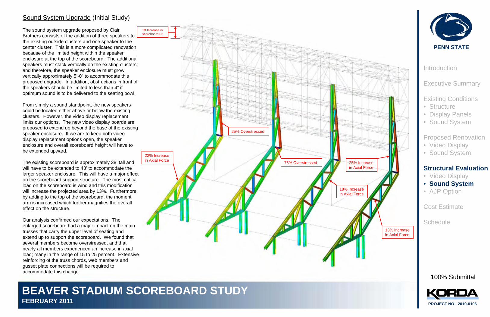
Sound System Upgrade (Initial Study)
The sound system upgrade proposed by Clair Brothers consists of the addition of three speakers to the existing outside clusters and one speaker to the center cluster. This is a more complicated renovation because of the limited height within the speaker enclosure at the top of the scoreboard. The additional speakers must stack vertically on the existing clusters; and therefore, the speaker enclosure must grow vertically approximately 5’-0” to accommodate this proposed upgrade. In addition, obstructions in front of the speakers should be limited to less than 4” if optimum sound is to be delivered to the seating bowl.
From simply a sound standpoint, the new speakers could be located either above or below the existing clusters. However, the video display replacement limits our options. The new video display boards are proposed to extend up beyond the base of the existing speaker enclosure. If we are to keep both video display replacement options open, the speaker enclosure and overall scoreboard height will have to be extended upward.
The existing scoreboard is approximately 38’ tall and will have to be extended to 43’ to accommodate the larger speaker enclosure. This will have a major effect on the scoreboard support structure. The most critical load on the scoreboard is wind and this modification will increase the projected area by 13%. Furthermore, by adding to the top of the scoreboard, the moment arm is increased which further magnifies the overall effect on the structure.
Our analysis confirmed our expectations. The enlarged scoreboard had a major impact on the main trusses that carry the upper level of seating and extend up to support the scoreboard. We found that several members become overstressed, and that nearly all members experienced an increase in axial load; many in the range of 15 to 25 percent. Extensive reinforcing of the truss chords, web members and gusset plate connections will be required to accommodate this change.
25% Overstressed
76% Overstressed
13% Increase in Axial Force
18% Increase in Axial Force
22% Increase in Axial Force
25% Increase in Axial Force
5ft Increase in Scoreboard Ht.
Introduction
Executive Summary
Existing Conditions• Structure• Display Panels• Sound System
Proposed Renovation• Video Display• Sound System
Structural Evaluation• Video Display• Sound System• AJP Option
Cost Estimate
Schedule
100% Submittal
PENN STATE
BEAVER STADIUM SCOREBOARD STUDYFEBRUARY 2011 PROJECT NO.: 2010-0106
100% Submittal
Structural Renovation – AJP Option
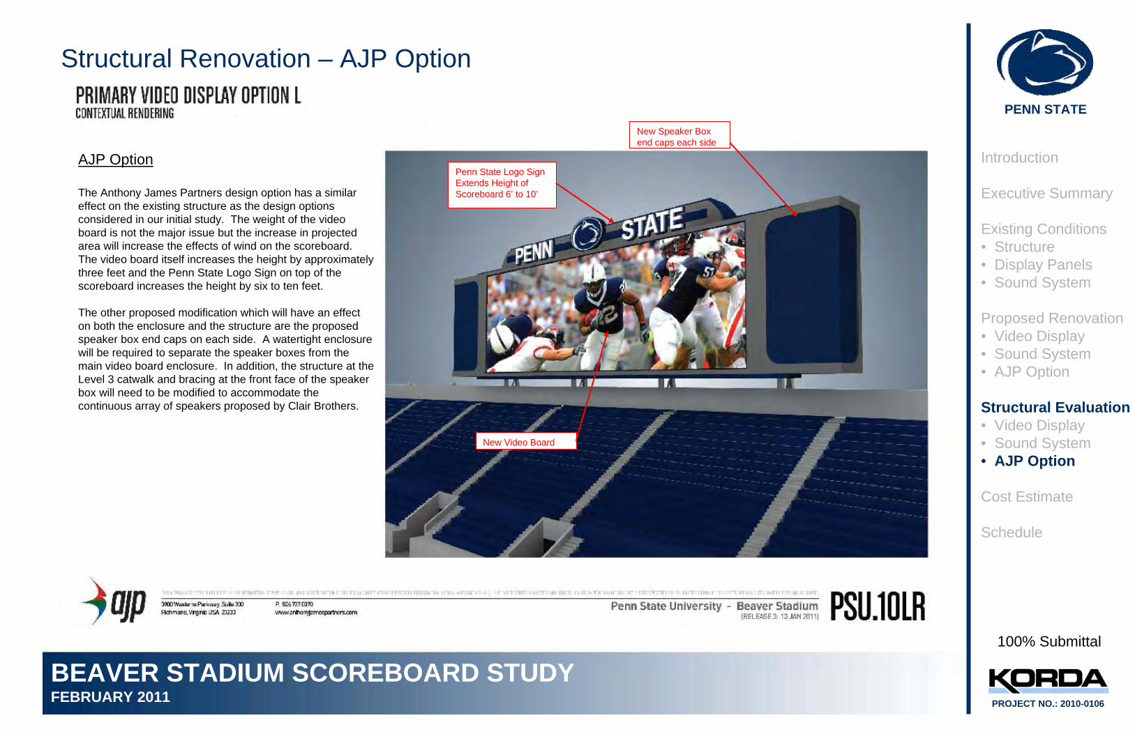
AJP Option
The Anthony James Partners design option has a similar effect on the existing structure as the design options considered in our initial study. The weight of the video board is not the major issue but the increase in projected area will increase the effects of wind on the scoreboard. The video board itself increases the height by approximately three feet and the Penn State Logo Sign on top of the scoreboard increases the height by six to ten feet.
The other proposed modification which will have an effect on both the enclosure and the structure are the proposed speaker box end caps on each side. A watertight enclosure will be required to separate the speaker boxes from the main video board enclosure. In addition, the structure at the Level 3 catwalk and bracing at the front face of the speaker box will need to be modified to accommodate the continuous array of speakers proposed by Clair Brothers.
Introduction
Executive Summary
Existing Conditions• Structure• Display Panels• Sound System
Proposed Renovation• Video Display• Sound System• AJP Option
Structural Evaluation• Video Display• Sound System• AJP Option
Cost Estimate
Schedule
Penn State Logo Sign Extends Height of Scoreboard 6’ to 10’
New Video Board
New Speaker Box end caps each side
PENN STATE
BEAVER STADIUM SCOREBOARD STUDYFEBRUARY 2011 PROJECT NO.: 2010-0106
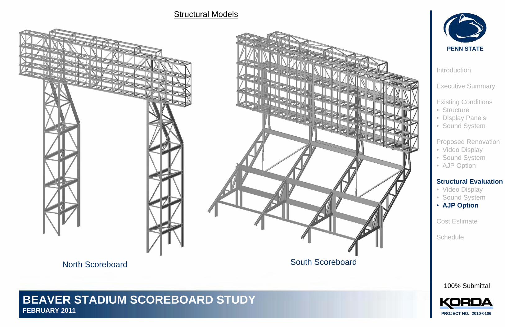
Structural Models
North Scoreboard South Scoreboard
100% Submittal
Introduction
Executive Summary
Existing Conditions• Structure• Display Panels• Sound System
Proposed Renovation• Video Display• Sound System• AJP Option
Structural Evaluation• Video Display• Sound System• AJP Option
Cost Estimate
Schedule
PENN STATE
BEAVER STADIUM SCOREBOARD STUDYFEBRUARY 2011 PROJECT NO.: 2010-0106
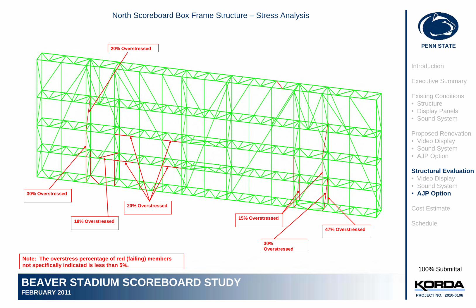
North Scoreboard Box Frame Structure – Stress Analysis
100% Submittal
30% Overstressed
18% Overstressed
20% Overstressed
15% Overstressed
47% Overstressed
30% Overstressed
20% Overstressed
Note: The overstress percentage of red (failing) members not specifically indicated is less than 5%.
Introduction
Executive Summary
Existing Conditions• Structure• Display Panels• Sound System
Proposed Renovation• Video Display• Sound System• AJP Option
Structural Evaluation• Video Display• Sound System• AJP Option
Cost Estimate
Schedule
PENN STATE
BEAVER STADIUM SCOREBOARD STUDYFEBRUARY 2011 PROJECT NO.: 2010-0106
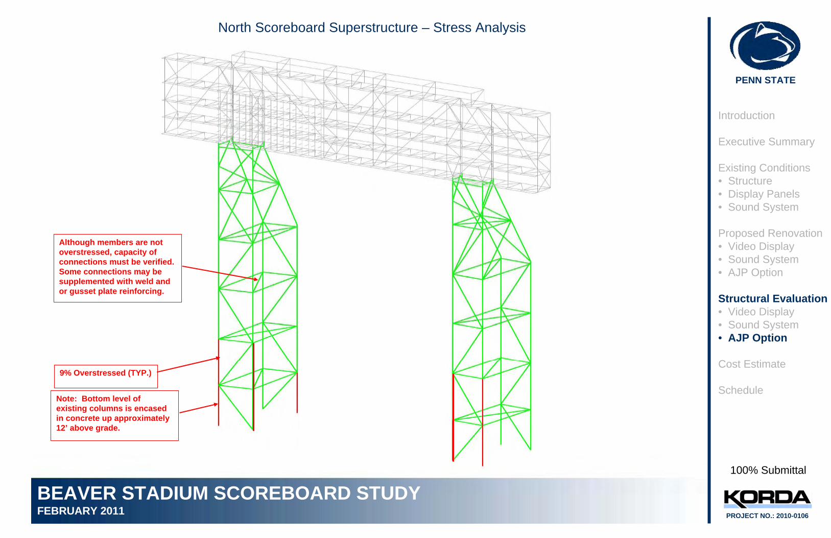
North Scoreboard Superstructure – Stress Analysis
100% Submittal
9% Overstressed (TYP.)
Introduction
Executive Summary
Existing Conditions• Structure• Display Panels• Sound System
Proposed Renovation• Video Display• Sound System• AJP Option
Structural Evaluation• Video Display• Sound System• AJP Option
Cost Estimate
Schedule
Although members are not overstressed, capacity of connections must be verified. Some connections may be supplemented with weld and or gusset plate reinforcing.
Note: Bottom level of existing columns is encased in concrete up approximately 12’ above grade.
PENN STATE
BEAVER STADIUM SCOREBOARD STUDYFEBRUARY 2011 PROJECT NO.: 2010-0106
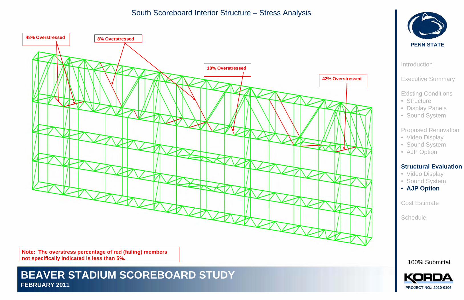
South Scoreboard Interior Structure – Stress Analysis
100% Submittal
48% Overstressed 8% Overstressed
18% Overstressed
42% Overstressed
Introduction
Executive Summary
Existing Conditions• Structure• Display Panels• Sound System
Proposed Renovation• Video Display• Sound System• AJP Option
Structural Evaluation• Video Display• Sound System• AJP Option
Cost Estimate
Schedule
Note: The overstress percentage of red (failing) members not specifically indicated is less than 5%.
PENN STATE
BEAVER STADIUM SCOREBOARD STUDYFEBRUARY 2011 PROJECT NO.: 2010-0106
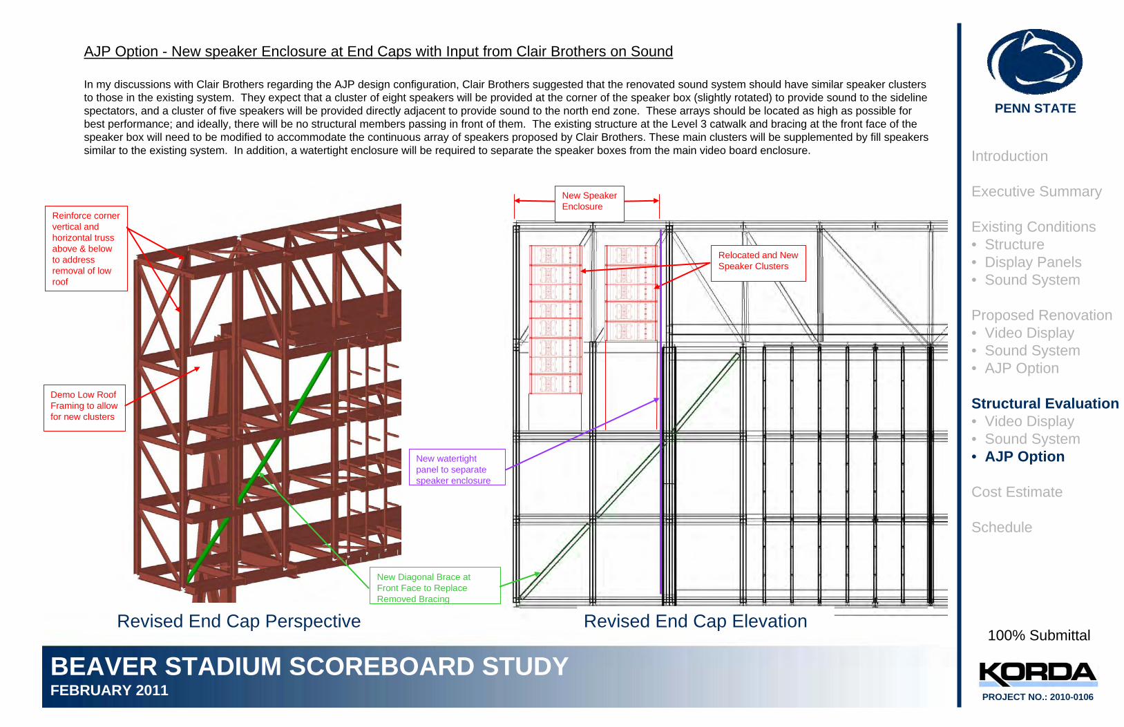
AJP Option - New speaker Enclosure at End Caps with Input from Clair Brothers on Sound
In my discussions with Clair Brothers regarding the AJP design configuration, Clair Brothers suggested that the renovated sound system should have similar speaker clusters to those in the existing system. They expect that a cluster of eight speakers will be provided at the corner of the speaker box (slightly rotated) to provide sound to the sideline spectators, and a cluster of five speakers will be provided directly adjacent to provide sound to the north end zone. These arrays should be located as high as possible for best performance; and ideally, there will be no structural members passing in front of them. The existing structure at the Level 3 catwalk and bracing at the front face of the speaker box will need to be modified to accommodate the continuous array of speakers proposed by Clair Brothers. These main clusters will be supplemented by fill speakers similar to the existing system. In addition, a watertight enclosure will be required to separate the speaker boxes from the main video board enclosure. Introduction
Executive Summary
Existing Conditions• Structure• Display Panels• Sound System
Proposed Renovation• Video Display• Sound System• AJP Option
Structural Evaluation• Video Display• Sound System• AJP Option
Cost Estimate
Schedule
100% Submittal
New watertight panel to separate speaker enclosure
Revised End Cap ElevationRevised End Cap Perspective
New Diagonal Brace at Front Face to Replace Removed Bracing
Demo Low Roof Framing to allow for new clusters
Reinforce corner vertical and horizontal truss above & below to address removal of low roof
Relocated and New Speaker Clusters
New Speaker Enclosure
PENN STATE
BEAVER STADIUM SCOREBOARD STUDYFEBRUARY 2011 PROJECT NO.: 2010-0106
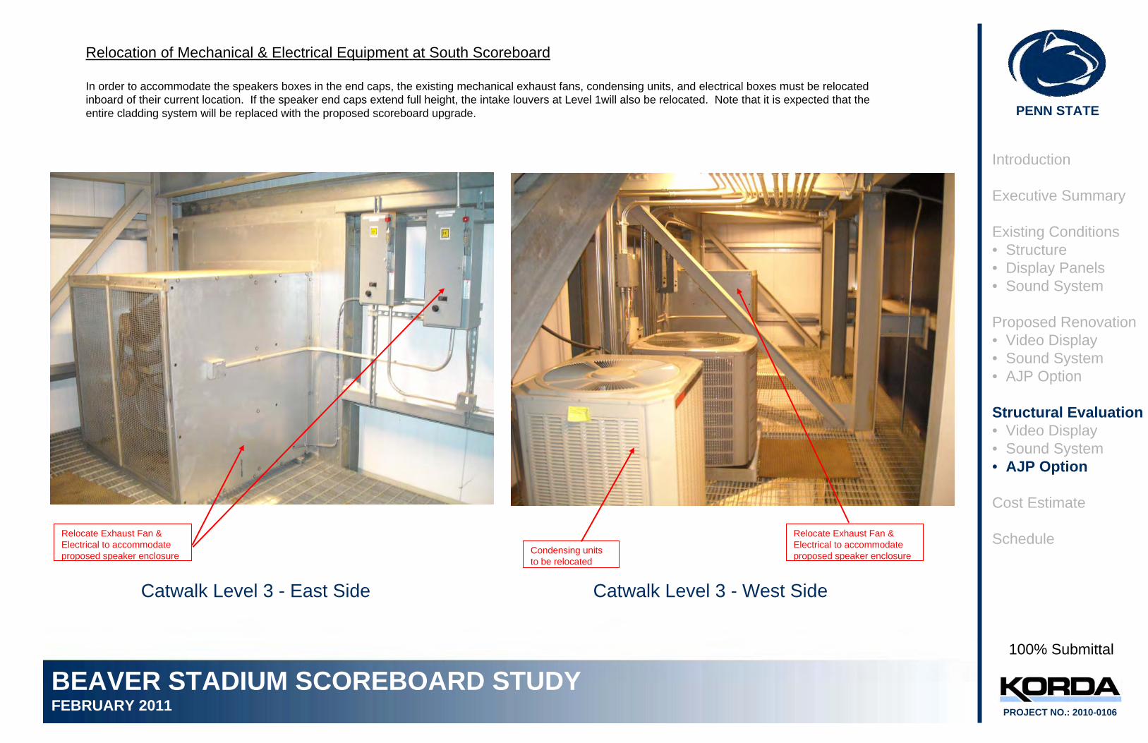
Relocation of Mechanical & Electrical Equipment at South Scoreboard
In order to accommodate the speakers boxes in the end caps, the existing mechanical exhaust fans, condensing units, and electrical boxes must be relocated inboard of their current location. If the speaker end caps extend full height, the intake louvers at Level 1will also be relocated. Note that it is expected that the entire cladding system will be replaced with the proposed scoreboard upgrade.
Introduction
Executive Summary
Existing Conditions• Structure• Display Panels• Sound System
Proposed Renovation• Video Display• Sound System• AJP Option
Structural Evaluation• Video Display• Sound System• AJP Option
Cost Estimate
Schedule
Catwalk Level 3 - East Side
Relocate Exhaust Fan & Electrical to accommodate proposed speaker enclosure
100% Submittal
Catwalk Level 3 - West Side
Condensing units to be relocated
Relocate Exhaust Fan & Electrical to accommodate proposed speaker enclosure
PENN STATE
BEAVER STADIUM SCOREBOARD STUDYFEBRUARY 2011 PROJECT NO.: 2010-0106
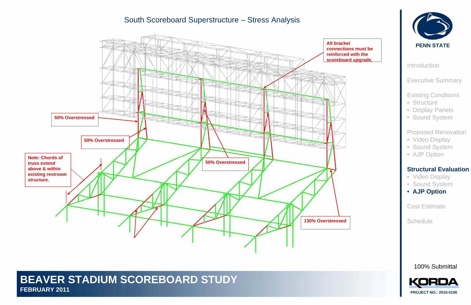
South Scoreboard Superstructure – Stress Analysis
100% Submittal
50% Overstressed
50% Overstressed
Note: Chords of truss extend above & within existing restroom structure.
130% Overstressed
50% Overstressed
Introduction
Executive Summary
Existing Conditions• Structure• Display Panels• Sound System
Proposed Renovation• Video Display• Sound System• AJP Option
Structural Evaluation• Video Display• Sound System• AJP Option
Cost Estimate
Schedule
All bracket connections must be reinforced with the scoreboard upgrade.
PENN STATE
BEAVER STADIUM SCOREBOARD STUDYFEBRUARY 2011 PROJECT NO.: 2010-0106
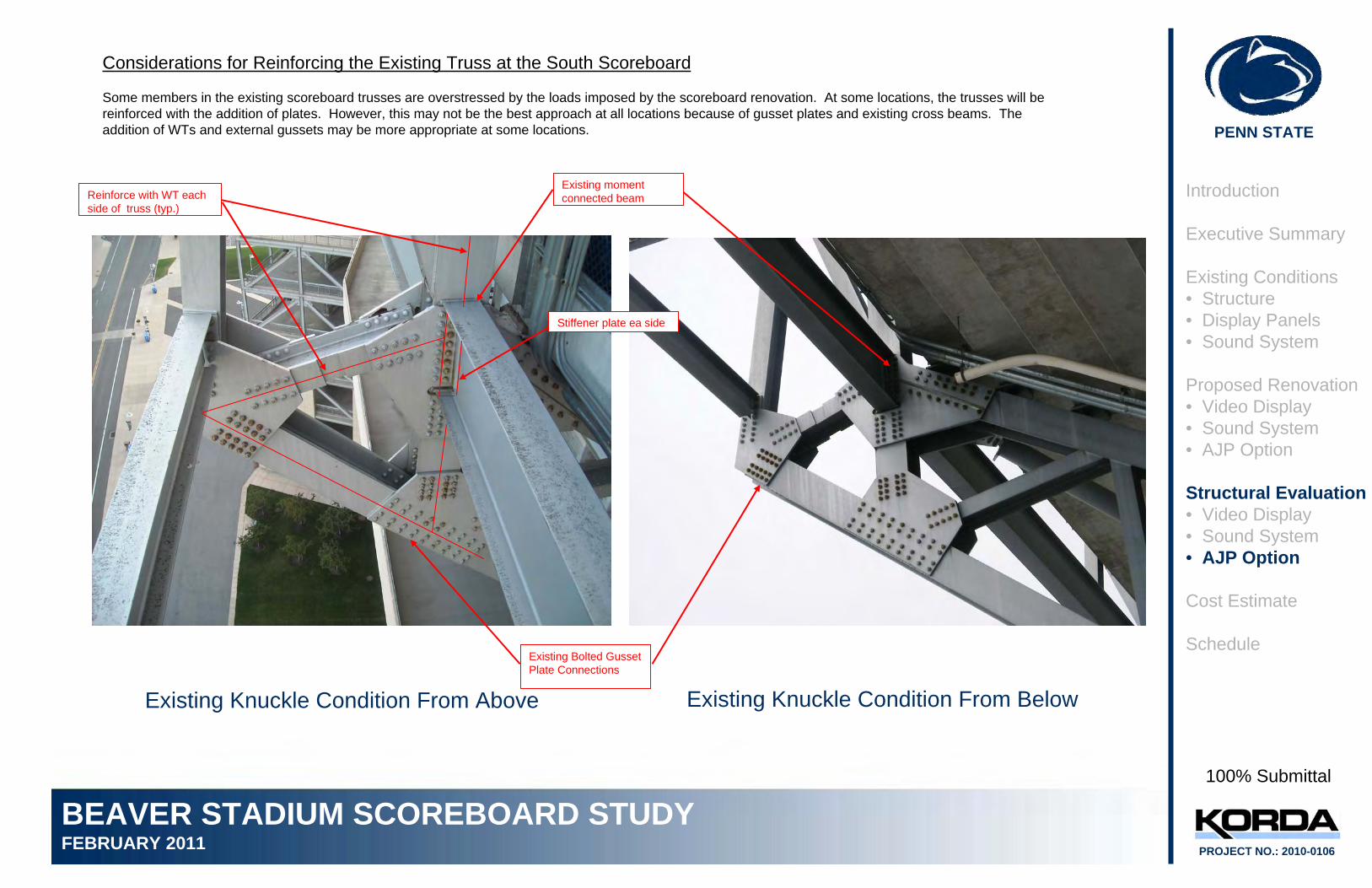
Considerations for Reinforcing the Existing Truss at the South Scoreboard
Some members in the existing scoreboard trusses are overstressed by the loads imposed by the scoreboard renovation. At some locations, the trusses will be reinforced with the addition of plates. However, this may not be the best approach at all locations because of gusset plates and existing cross beams. The addition of WTs and external gussets may be more appropriate at some locations.
Introduction
Executive Summary
Existing Conditions• Structure• Display Panels• Sound System
Proposed Renovation• Video Display• Sound System• AJP Option
Structural Evaluation• Video Display• Sound System• AJP Option
Cost Estimate
Schedule
Existing Knuckle Condition From Above Existing Knuckle Condition From Below
100% Submittal
Existing Bolted Gusset Plate Connections
Existing moment connected beam
Stiffener plate ea side
Reinforce with WT each side of truss (typ.)
PENN STATE
BEAVER STADIUM SCOREBOARD STUDYFEBRUARY 2011 PROJECT NO.: 2010-0106
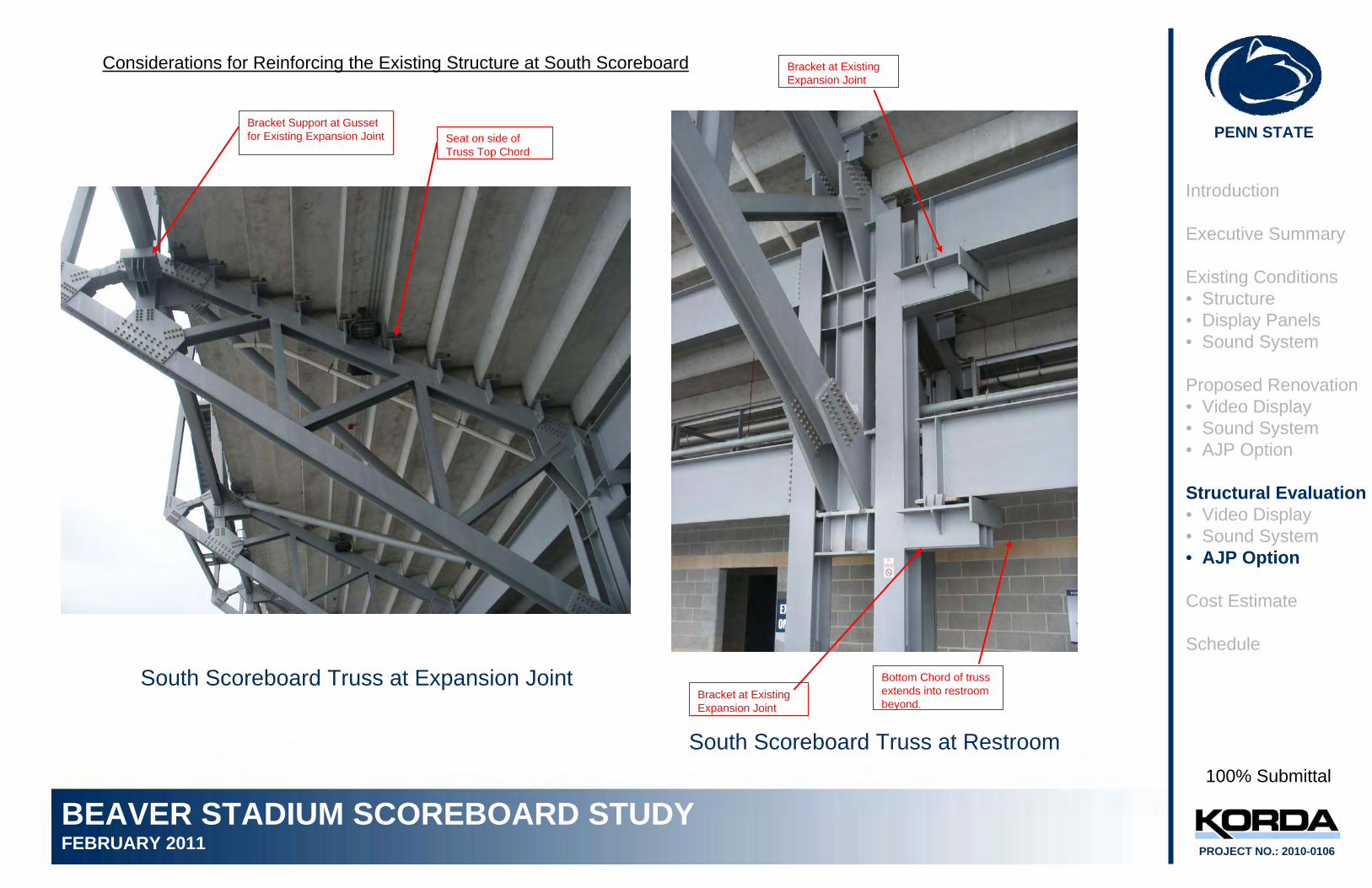
Considerations for Reinforcing the Existing Structure at South Scoreboard
Introduction
Executive Summary
Existing Conditions• Structure• Display Panels• Sound System
Proposed Renovation• Video Display• Sound System• AJP Option
Structural Evaluation• Video Display• Sound System• AJP Option
Cost Estimate
Schedule
South Scoreboard Truss at Expansion Joint
South Scoreboard Truss at Restroom
100% Submittal
Bracket Support at Gusset for Existing Expansion Joint
Bracket at Existing Expansion Joint
Bottom Chord of truss extends into restroom beyond.
Bracket at Existing Expansion Joint
Seat on side of Truss Top Chord

QUESTIONNAIRE
Beaver Stadium Scoreboard Replacement University Park
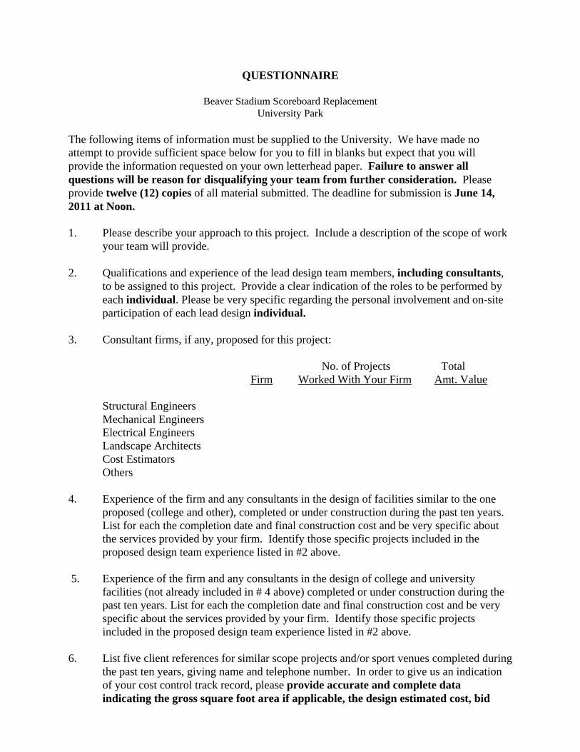
The following items of information must be supplied to the University. We have made no attempt to provide sufficient space below for you to fill in blanks but expect that you will provide the information requested on your own letterhead paper. Failure to answer all questions will be reason for disqualifying your team from further consideration. Please provide twelve (12) copies of all material submitted. The deadline for submission is June 14, 2011 at Noon. 1. Please describe your approach to this project. Include a description of the scope of work
your team will provide. 2. Qualifications and experience of the lead design team members, including consultants,
to be assigned to this project. Provide a clear indication of the roles to be performed by each individual. Please be very specific regarding the personal involvement and on-site participation of each lead design individual.
3. Consultant firms, if any, proposed for this project: No. of Projects Total Firm Worked With Your Firm Amt. Value Structural Engineers Mechanical Engineers Electrical Engineers Landscape Architects Cost Estimators Others 4. Experience of the firm and any consultants in the design of facilities similar to the one
proposed (college and other), completed or under construction during the past ten years. List for each the completion date and final construction cost and be very specific about the services provided by your firm. Identify those specific projects included in the proposed design team experience listed in #2 above.
5. Experience of the firm and any consultants in the design of college and university
facilities (not already included in # 4 above) completed or under construction during the past ten years. List for each the completion date and final construction cost and be very specific about the services provided by your firm. Identify those specific projects included in the proposed design team experience listed in #2 above.
6. List five client references for similar scope projects and/or sport venues completed during
the past ten years, giving name and telephone number. In order to give us an indication of your cost control track record, please provide accurate and complete data indicating the gross square foot area if applicable, the design estimated cost, bid
Questionnaire Beaver Stadium Scoreboard Replacement University Park Page 2
cost, the final total construction cost and the bid date for each project. Please explain the reason for any major discrepancies between estimated, bid and final construction costs. Please make sure the telephone number of each client reference is current.
7. Graphic examples of selected relevant projects personally done by the lead designers
including brief descriptions and completion date. 8. Please provide a proposed schedule for each component of this project in graphic form
allowing one week for any necessary Penn State University review. Assume the design process will start in August, 2011.
9. List errors and omissions insurance coverage.
10. Number of personnel in present firm(s): Architects _____ Engineers _____ Landscape Architects _____ Others _____
Which of the above are professionally registered?
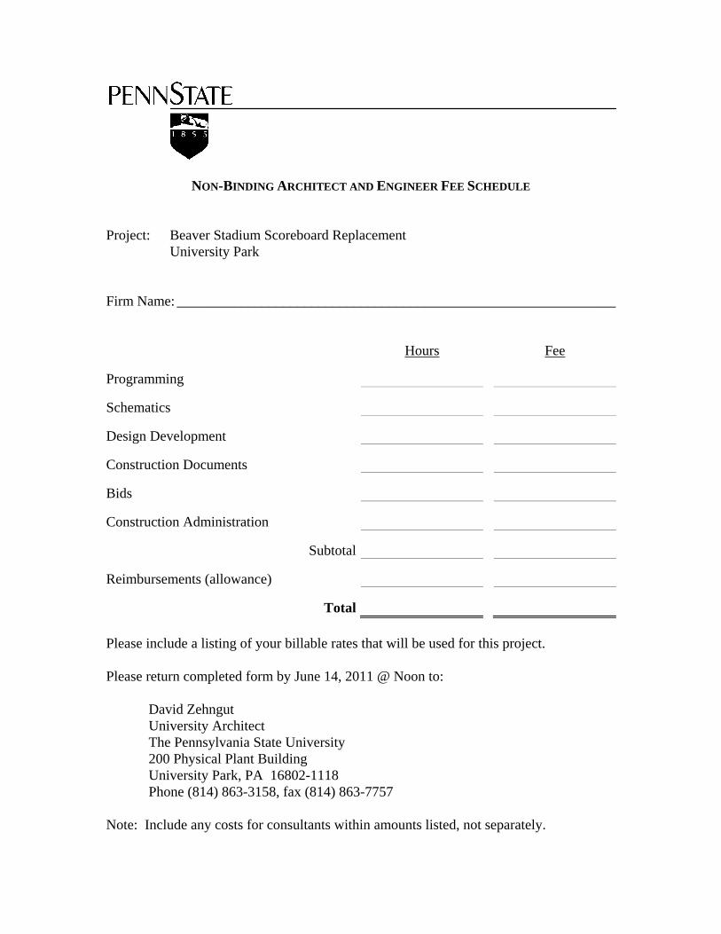
NON-BINDING ARCHITECT AND ENGINEER FEE SCHEDULE Project: Beaver Stadium Scoreboard Replacement University Park Firm Name: ______________________________________________________________ Hours Fee
Programming
Schematics
Design Development
Construction Documents
Bids
Construction Administration
Subtotal
Reimbursements (allowance)
Total Please include a listing of your billable rates that will be used for this project. Please return completed form by June 14, 2011 @ Noon to: David Zehngut University Architect The Pennsylvania State University 200 Physical Plant Building University Park, PA 16802-1118 Phone (814) 863-3158, fax (814) 863-7757 Note: Include any costs for consultants within amounts listed, not separately.
Form of Agreement 1-P Page 1 of 22
08/2010
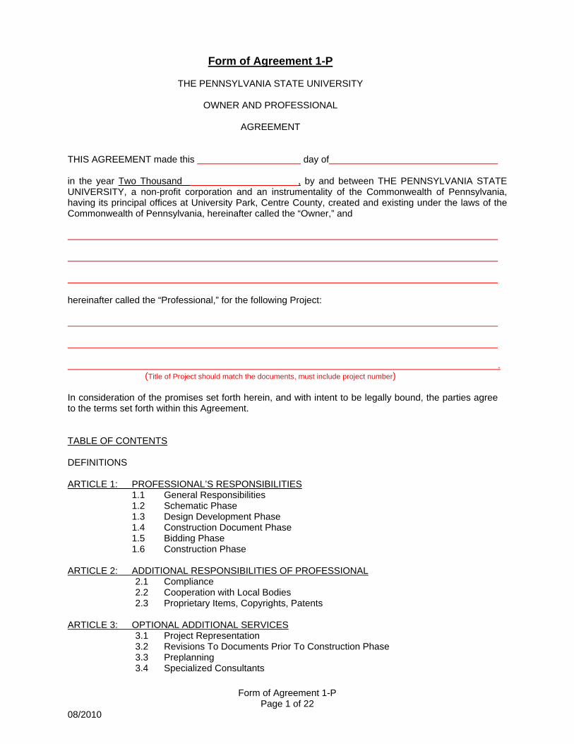
Form of Agreement 1-P
THE PENNSYLVANIA STATE UNIVERSITY
OWNER AND PROFESSIONAL
AGREEMENT
THIS AGREEMENT made this day of in the year Two Thousand , by and between THE PENNSYLVANIA STATE UNIVERSITY, a non-profit corporation and an instrumentality of the Commonwealth of Pennsylvania, having its principal offices at University Park, Centre County, created and existing under the laws of the Commonwealth of Pennsylvania, hereinafter called the “Owner,” and hereinafter called the “Professional,” for the following Project: .
(Title of Project should match the documents, must include project number) In consideration of the promises set forth herein, and with intent to be legally bound, the parties agree to the terms set forth within this Agreement. TABLE OF CONTENTS DEFINITIONS ARTICLE 1: PROFESSIONAL’S RESPONSIBILITIES 1.1 General Responsibilities 1.2 Schematic Phase 1.3 Design Development Phase 1.4 Construction Document Phase 1.5 Bidding Phase 1.6 Construction Phase
ARTICLE 2: ADDITIONAL RESPONSIBILITIES OF PROFESSIONAL
2.1 Compliance 2.2 Cooperation with Local Bodies 2.3 Proprietary Items, Copyrights, Patents
ARTICLE 3: OPTIONAL ADDITIONAL SERVICES 3.1 Project Representation 3.2 Revisions To Documents Prior To Construction Phase 3.3 Preplanning 3.4 Specialized Consultants
Form of Agreement 1-P Page 2 of 22
08/2010
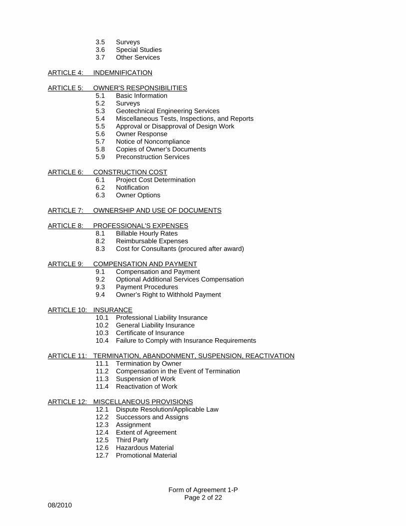
3.5 Surveys 3.6 Special Studies 3.7 Other Services
ARTICLE 4: INDEMNIFICATION ARTICLE 5: OWNER'S RESPONSIBILITIES
5.1 Basic Information 5.2 Surveys 5.3 Geotechnical Engineering Services 5.4 Miscellaneous Tests, Inspections, and Reports 5.5 Approval or Disapproval of Design Work 5.6 Owner Response 5.7 Notice of Noncompliance 5.8 Copies of Owner’s Documents 5.9 Preconstruction Services
ARTICLE 6: CONSTRUCTION COST 6.1 Project Cost Determination 6.2 Notification 6.3 Owner Options
ARTICLE 7: OWNERSHIP AND USE OF DOCUMENTS ARTICLE 8: PROFESSIONAL'S EXPENSES
8.1 Billable Hourly Rates 8.2 Reimbursable Expenses 8.3 Cost for Consultants (procured after award)
ARTICLE 9: COMPENSATION AND PAYMENT
9.1 Compensation and Payment 9.2 Optional Additional Services Compensation 9.3 Payment Procedures 9.4 Owner’s Right to Withhold Payment
ARTICLE 10: INSURANCE 10.1 Professional Liability Insurance 10.2 General Liability Insurance 10.3 Certificate of Insurance 10.4 Failure to Comply with Insurance Requirements
ARTICLE 11: TERMINATION, ABANDONMENT, SUSPENSION, REACTIVATION 11.1 Termination by Owner 11.2 Compensation in the Event of Termination 11.3 Suspension of Work 11.4 Reactivation of Work
ARTICLE 12: MISCELLANEOUS PROVISIONS 12.1 Dispute Resolution/Applicable Law 12.2 Successors and Assigns 12.3 Assignment 12.4 Extent of Agreement 12.5 Third Party 12.6 Hazardous Material 12.7 Promotional Material
Form of Agreement 1-P Page 3 of 22
08/2010
12.8 Terms/General Conditions
ARTICLE 13: SCHEDULE OF EXHIBITS DEFINITIONS: Contract Documents consist of the General Conditions of the Contract, Drawings, Specifications, Addenda issued prior to receipt of Trade Contract bids, Form of Proposal, other documents listed in the Agreement and those modifications to the Contract as follows: Owner's written authorization to the Contractor for changes to the Scope of Work, a Change Order, and a written order for a minor change in the Work issued by the Professional. Contractor means the person or entity retained by the Owner to perform Work for the project and includes the Contractor’s Representative. Construction Budget means the project construction cost limit established by the Owner. Construction Cost Estimate means a detailed breakdown of all costs associated with the scope of work required to meet the project requirements projected to the mid-point of construction. Final Completion means the point at which the project is fully completed in accordance with the Contract Documents (this includes all physical/construction obligations, administrative obligations, and punch list obligations). The Owner is The Pennsylvania State University, a non-profit corporation created and existing under the laws of the Commonwealth of Pennsylvania, and an instrumentality of the Commonwealth of Pennsylvania; this term shall include the Owner and/or the Owner's authorized representative. The Pennsylvania State University Design and Construction Standards means those design and construction standards as set forth at: http://www.opp.psu.edu/construction/standards/design_standards.cfm. The Professional is the person lawfully licensed to practice architecture or engineering, or the firm employed to provide architectural or engineering services, for the referenced project. The term "Professional" shall mean the Professional or the Professional's authorized representative. The Project shall comprise the Work defined by the Contract Documents and may include work by the Owner or other Separate Contractors, Trade Contractors, Sub-Trade Contractors or the Professional. The Scope of Work means the work reasonably contemplated, required, implied, or reasonably inferable by the Contract Documents or normal standards of the building trades, whether or not explicitly contained in the Contract Documents. Services means the services provided by the Professional and/or by consultants retained by the Professional for the Project. Substantial Completion shall mean that stage in the progression of the Work when the Work is sufficiently complete in accordance with this Contract that the Owner can enjoy beneficial use or occupancy of the Work and can utilize the Work for its intended purpose. Work means the construction and services necessary or incidental to fulfill the Contractor’s or Professional’s obligations for the Project in conformance with the agreement between the Owner and Contractor or the Owner and Professional.
Form of Agreement 1-P Page 4 of 22
08/2010
ARTICLE 1: PROFESSIONAL’S RESPONSIBILTIES 1.1 General Responsibilities 1.1.1 The Professional shall furnish or provide the architectural and engineering services as outlined herein, and any other relevant data, specifications or documents, as necessary for a complete project. The Professional shall expeditiously perform said services in a manner consistent with professional skill, care, and the orderly progress of the work. In carrying out all obligations pursuant to this Agreement, including the furnishing of Construction Documents, the Professional shall in all respects conform to the applicable professional standard of care. 1.1.2 By executing this Agreement, the Professional represents to the Owner that the Professional possesses the requisite skill, expertise, and credentials to perform the required services, and that Professional is licensed to practice by all public entities having jurisdiction over the Professional and the Project. The Professional further represents to the Owner that the Professional will maintain all necessary licenses, permits, or other authorizations necessary to act as Professional for the Project until the Professional's remaining duties hereunder have been satisfied. The Professional assumes full responsibility to the Owner for the negligent acts and omissions of the Professional's consultants or others employed or retained by the Professional in connection with the Project. 1.1.3 Execution of this Agreement by the Professional constitutes a representation that the Professional has become familiar with the Project site and the local conditions under which the Project is to be implemented. 1.1.4 The Professional shall provide the services required by this agreement in conformance with the most recent project schedule approved by the Owner. 1.1.5 The Professional shall provide Professional Services, per Exhibit A and per this agreement, in accordance with The Pennsylvania State University Design and Construction Standards referenced in Exhibit C. 1.1.6 The Professional is responsible for additional submission and presentation requirements as outlined for Board of Trustee approval or other administrative approval. 1.1.7 If a Construction Manager is hired by the Owner it will be the responsibility of the Professional to collaborate and work in concert with the Construction Manager throughout the duration of the project. Furthermore, the Professional shall reconcile all cost estimates with the Construction Manager. 1.1.8 Payment of the Professional’s fees, as per in Article 9, is contingent upon completion of the documents per the attached schedule. 1.1.9 Adherence to Time Schedule. The Professional shall strictly adhere to submission schedules as set forth in this Agreement. Should the Professional become aware that he will be unable to meet any of the dates set forth in this Agreement, the Professional shall immediately notify the Owner in writing.
The Professional shall include in the notice the reason(s) for the Professional’s inability to meet the date(s) and a request that the Owner amend the time schedule.
The Owner shall review the Professional’s notice and determine whether or not to amend the time schedule.
If the Owner determines that the delay is due to the fault of the Professional, the Owner may amend the schedule and direct the Professional to expeditiously proceed with the design of the project, in which case the Owner may hold the Professional responsible for any costs attributable to the delay, or

Form of Agreement 1-P Page 5 of 22
08/2010
terminate the Agreement for default of the Professional, in accordance with the provisions of this Agreement. If the Owner determines that the delay is not due to the fault of the Professional, the Owner may amend the time schedule. The Professional agrees that such an amendment of the time schedule is his exclusive remedy for a delay and that he may not make any claims against the Owner for increased costs due to the delay. 1.1.10 Building Information Modeling (BIM). The project will be designed using Building Information Modeling (BIM). Professionals shall use BIM application(s) and software to develop project designs. Digital modeling information shall be provided to the Owner and Construction Manager for the following building systems: ALL DISCIPLINES. This may include, but is not limited to, architectural, site, civil, structural, mechanical, electrical, safety and security, controls, fire suppression and alarms, building automation and other systems. This includes relevant model element information to be used for future integration into the Owner’s facilities management system. This may include, but is not limited to, hyperlinks to O&M manuals, preventative maintenance schedules, and analysis data. The Professional shall develop the Facility Data consisting of a set of intelligent elements for the Model (e.g., doors, air handlers, electrical panels). This Facility Data shall include all material definitions and attributes that are necessary for the Project facility design and construction. Professional shall use the Model to derive accurate Construction Documents. All submitted BIM Models and associated Facility Data shall be fully compatible with Autodesk Revit 9.0 or higher. The Professional shall be responsible for updating the model during design, pre-construction, construction and post-construction record documentation (including change orders, RFI and submissions). A read-only, coordinated model shall be delivered to the Construction Manager for pre-construction coordination services and as required during construction. Collaboration with the Construction Manager is of utmost importance and attendance (co-location or web teleconference) at periodic coordination meetings will be required. The level of detail, model content, information exchange format, and party responsible for modeling and information input will be decided upon during contract negotiations. The basis for these negotiations will be the Penn State BIM Project Execution Plan template (PSU BIM Template), which is available on the OPP website. The Professional shall develop a project specific BIM Execution Plan (BIM Plan) documenting the collaborative process in which BIM will be implemented throughout the lifecycle of the project. The BIM Plan shall utilize the requirements identified here and in the PSU BIM Template. It shall be submitted for approval by the Owner and Construction Manager prior to the schematic design phase. Implement quality control (QC) parameters for the Model, including the procedures described in section I of the PSU BIM Template. As a minimum, provide the following: model standards checks, CAD standards checks, and other parameters. The following uses of BIM are required: design authoring, design reviews, 3D design coordination, energy analysis, building envelope analysis, and architectural renderings. Reference Section D.2 of the PSU BIM Template. The Professional shall perform design and construction reviews at each submittal stage to test the Model to ensure the design intent has been followed and that there are no unintended elements in the Model.
The Professional shall locate conflicting spatial data in the Model where two elements are occupying the same space. Log hard interferences (e.g., mechanical vs. structural or mechanical vs. mechanical overlaps in the same location) and soft interferences, (e.g., conflicts regarding equipment clearance, service access, fireproofing, insulation) in a written report and resolve. The Professional shall implement a process in which BIM software uses the model and energy attributes to determine the most effective engineering methods based on design specifications. These analysis
Form of Agreement 1-P Page 6 of 22
08/2010
tools and performance simulations can significantly improve the energy consumption during lifecycle operations. The Professional shall provide submittals in compliance with BIM Plan deliverables at stages as described in section B.8 of the PSU BIM Template. At each Design Stage, The Professional will provide PSU with the following:
The Model (Revit) and Facility Data (various). A 3-D interactive review format of the Model in Autodesk Navisworks, Adobe 3D PDF 7.0 (or
later), or other format per Plan requirements. The file format for reviews can change between submittals.
A list of all submitted files. The list should include a description, directory, and file name for each file submitted. For all CAD sheets, include the sheet title and sheet number. Identify files that have been produced from the submitted Model and Facility Data.
All costs associated with BIM, including model updates during construction, shall be included in the base contract price (contract Article 9.1.1). An as-built BIM model shall be submitted by the Design Professional to the Owner upon Final Completion of the Work for the agreed upon building systems listed in this agreement. The BIM digital information is to be considered the Architect’s work product and as such, under Article 7 of the contract, is ultimately the Owner’s property. Any questions or variations from this shall be discussed and agreed upon with the OPP BIM Manager or Manager of Design Services. 1.1.11 Contractor Design-Assist. The Owner anticipates utilizing contractor/vendor design-assist on some aspects of the project. If utilized, the Professional will assume the responsibility for incorporation of the design assist information into the overall design. 1.1.12 LEED Responsibility for Project. The Professional shall design the project to meet the LEED target certification level and shall undertake all reasonable and necessary efforts to bring about implementation of the design specifications in a manner that will meet the LEED target certification level, including coordination with the Contractor(s) and subcontractors. The Professional shall be primarily responsible for identifying the listing of credits to be achieved during the project in an effort to meet the certification level. The Professional shall also be responsible for preparing all documentation required for submission. The Professional shall use as a guide The Pennsylvania State University LEED Policy to be provided by the Owner. 1.2 Schematic Phase The Professional shall review and comply with the Project program and The Pennsylvania State University Design and Construction Standards, both as furnished by the Owner, and shall conduct appropriate visits to the Project site. The Professional shall then provide to Owner a preliminary evaluation of the program and schedule and a preliminary construction cost estimate. The Professional shall review with the Owner alternative approaches to project design and construction, as may be required. After the Owner has approved the Project scope, cost estimate and schedule as submitted by the Professional, the Professional shall prepare and submit to the Owner, for approval, Schematic Design Documents and any other documents required by the Owner. Refer to the Design Phase Submittal Requirements document available on the Office of Physical Plant web page for a listing of submission requirements for the Schematic Phase. Following approval of Schematic Design Documents and any other documents required at such phase by the Owner, The Professional shall submit a Construction Cost Estimate. The estimate shall be determined by the Professional using the most accurate means available.
Form of Agreement 1-P Page 7 of 22
08/2010
1.3 Design Development Phase After approval by the Owner of the Schematic Design Documents, and any Owner-authorized changes in Project scope or construction budget, the Professional shall prepare and submit, for approval by Owner and any government authorities, Design Development drawings and any other documents required by the Owner for said approval. These drawings and other documents shall fix building size, delineate and describe the various construction materials to be used, and indicate the structural, mechanical, and electrical systems upon which the design is based. Refer to the Design Phase Submittal Requirements document available on the Office of Physical Plant web page for a listing of submission requirements for the Design Development Phase (noted as Preliminary and Design Phase in the document). The Professional shall provide an update of the Construction Cost Estimate and schedule and advise the Owner immediately of any adjustments. 1.4 Construction Document Phase After approval by the Owner of the Design Development Phase documents, and any further Owner-authorized changes in Project scope or construction budget, the Professional shall prepare and submit to the Owner, for approval, Construction Drawings and Specifications/Project Manual (hereinafter referred to as the "Construction Documents") required by the Owner for said approval. These Construction Documents shall delineate, detail, and completely specify all materials and equipment required to fully complete construction of the Project in every respect, consistent with current standards of the profession. The Construction Documents shall completely describe all work necessary to bid and construct the Project. Refer to the Design Phase Submittal Requirements document dated August 2006 (or any subsequent updates), available on the Office of Physical Plant web page, for a listing of submission requirements for the Construction Document Phase. Any review and approval by the Owner of the Construction Documents shall not be deemed to diminish the Professional's obligations under this Agreement. The Professional shall provide an update of the Construction Cost Estimate and schedule and shall advise the Owner immediately of any adjustments. The Professional shall be responsible for completing all of the appropriate planning modules, soil and erosion control plans, and other documents which may be required. The Professional shall be responsible for obtaining, on behalf of the Owner, whatever approvals are necessary to connect to non-Owner-owned utility lines. The Professional shall coordinate the Construction Documents for all of the separate Prime Contracts or trade packages, as required, to protect against omissions, conflicts, overlaps, or duplications of any items of work or materials on the Project. The Professional shall coordinate the services of all design consultants for the Project, including those retained by the Owner. 1.5 Bidding Phase After approval by the Owner of the Construction Documents, the Professional shall prepare and distribute all necessary bidding correspondence and documents, evaluate bid proposals, attend pre-bid or pre-award meetings, clarify the scope or intent of the Construction Documents, evaluate proposed subcontractors, and assist in the preparation of construction contracts.
Form of Agreement 1-P Page 8 of 22
08/2010
1.6 Construction Phase The Professional shall issue a set of construction documents that incorporate all bidding documents and revisions per addenda prior to the start of construction. The Professional's responsibility under this Agreement for Construction Phase services commences with the execution of the Contract(s) between the Contractor(s) and the Owner and terminates no earlier than the expiration of the Contractor's one-year guarantee period against defective materials, equipment, and/or workmanship. This paragraph is not intended to, and shall not be construed as, affecting in any way the calculation of any applicable legal statutes of limitation. Administration, by the Professional, of the construction contract(s) shall be as outlined below and in accordance with the General Conditions of the Contract for Construction. The Professional agrees to perform all of its obligations under this Agreement consistent with said General Conditions. The extent of the Professional's duties and responsibilities and the limitations of its authority as specified thereunder shall not be modified without written agreement between the Owner and the Professional. The Professional shall not be responsible for the Contractor's construction means, methods, techniques, sequences, or procedures, or for safety precautions and programs in connection with the work. However, if the Professional has actual knowledge of safety violations, the Professional shall immediately alert the relevant Contractor or Subcontractor and shall give prompt written notice to the Owner. The Professional shall not be responsible for the Contractor's failure to carry out the Work in accordance with the Contract Documents. The Professional shall not be deemed to have control over or charge of acts or omissions of the Contractor, Subcontractors, or their agents or employees, or any other persons performing portions of the Work. However, the Professional shall provide all required assistance to the Contractor, Subcontractors and/or agents and employees in order to facilitate the appropriate and timely performance of the Work. Furthermore, Professional is responsible for notifying the Owner and the Contractor of the Contractor's failure to carry out the Work in accordance with the Contract Documents upon observing such failure by the Contractor. 1.6.1 Schedule of Values. Upon receipt, the Professional shall carefully review and examine the Contractor's Schedule of Values, together with any supporting documentation or data which the Owner or the Professional may require from the Contractor. The purpose of such review and examination will be to protect the Owner from an unbalanced Schedule of Values which allocates greater value to certain elements of the Work than is indicated by such supporting documentation or data or than is reasonable under the circumstances. If the Schedule of Values is found to be inappropriate, or if the supporting documentation or data is deemed to be inadequate, and unless the Owner directs the Professional to the contrary in writing, the Schedule of Values shall be returned to the Contractor for revision or supporting documentation or data. After making such examination, if the Schedule of Values is found to be appropriate as submitted or, if necessary, as revised, the Professional shall sign the Schedule of Values thereby indicating the Professional's informed belief that the Schedule of Values constitutes a reasonable, balanced basis for payment of the Contract Price to the Contractor. The Professional shall not sign such Schedule of Values in the absence of such belief unless directed to do so, in writing, by the Owner. The Professional shall provide the Owner with a signed copy of the Schedule of Values after approval. 1.6.2 Access to Work. The Professional and its authorized representatives shall have full and safe access to the work at all times. 1.6.3 Visits to the Site/Inspection. The Professional and any consultants retained by the Professional, or an authorized and qualified representative, shall visit the Project periodically as required by the Owner during periods of active construction in order to review the progress of the work, and take such actions as are necessary or appropriate to achieve the requirements of the Construction Documents in the work of the responsible Contractors, including advising the Owner's representatives as to particular matters of concern. It shall also be the duty of the Professional to have its Consultants visit the site periodically as required during their respective Phases of the work, at such intervals as may reasonably be deemed
Form of Agreement 1-P Page 9 of 22
08/2010
necessary by the Owner and the Professional, to review their respective Phases of the work in order to achieve the requirements of the Construction Documents. The purpose of such site visits and reviews will be to determine the quality, quantity, and progress of the Work in comparison with the requirements of the Construction Documents. In making such reviews, the Professional shall exercise care to protect the Owner from defects or deficiencies in the Work, from unexcused delays in the schedule, and from overpayment to the Contractor. Following each such review, the Professional shall submit a written report within (5) calendar days of such review, together with any appropriate comments or recommendations, to the Owner. Whenever, in the Professional's opinion, it is necessary or advisable, the Professional shall require special inspection or testing of the Work in accordance with the provisions of the Construction Documents whether or not such Work is fabricated, installed, or completed. The Professional shall advise the Owner of all such occurrences requiring special inspection or testing of the Work and shall obtain prior approval from Owner before any funds are committed for inspection, beyond what has already been budgeted. 1.6.4 Approval of Payment to Contractors. Based on the Professional's review of the Project, the Professional will recommend, within seven (7) calendar days after receipt, approval or rejection of payment on the Application-Certificate of Payment. Approval of the Certificate of Payment shall constitute a representation by the Professional to the Owner that the work has progressed to the point indicated on the Application, and that to the best of the Professional's knowledge, information, and belief, the quality of the work is in accordance with the Contract Documents. The Professional shall make recommendations to the Owner for the withholding of any payment, or portion thereof, due to inadequate progress and/or performance of the Contract. The Professional agrees that time is of the essence with respect to this provision. 1.6.5 Interpreter. The Professional will be, in the first instance, the interpreter of the requirements of the Contract Documents. The Professional will, within a reasonable time as determined by the Owner, render such interpretation as it may deem necessary for the proper execution or Progress of the Work. All interpretations by the Professional shall be defined in writing and/or by drawing and shall be consistent with the intent of the Contract Documents. In addition to the above, the Professional shall be required to attend, at the determination of the Owner, any and all Project site conferences dealing with interpretation of the Contract Documents. The Professional's decisions, with Owner's prior approval, shall in matters relating to aesthetic effect be final if consistent with the intent of the Construction Documents. 1.6.6 Review of Contractor's Shop Drawings and Materials. The Professional shall review, approve, and process, subject to the right of review by the Owner, Shop Drawings to verify compliance with the Contract Documents and all product data, samples, materials, and other submissions of the Contractor required by the Contract Documents for conformity to and in harmony with the design concept of the Project and for compliance with the requirements of the Contract Documents. The Professional shall not approve any substitution of specified materials and/or equipment without first obtaining the Owner's consent. Approval by the Professional of the Contractor's submittal shall constitute the Professional's representation in accordance with Article 5 of the General Conditions of the Contract for Construction to the Owner that such submittal is in conformance with the Contract Documents. When the Contractor is required by the Contract Documents to provide professional certification of performance characteristics of materials, systems, or equipment, the Professional shall be entitled to rely upon such certification to establish that the materials, systems, or equipment will meet performance criteria required by the Contract Documents.
Form of Agreement 1-P Page 10 of 22
08/2010
Based on the priorities of the construction schedule, the Prime Contractor(s) shall submit a shop drawing submittal schedule on or before the Second Regular Job Conference. The Professional shall review and check the shop drawing submittal schedule within fourteen (14) calendar days of receipt from the Contractor. The Professional shall return the approved shop drawings, or detailed notation for resubmission, if required, within fourteen (14) calendar days after receipt from the Contractor unless mutually agreed otherwise by the Professional, Owner, and Contractor. The Professional shall act on any resubmissions within seven (7) calendar days of receipt thereof unless mutually agreed otherwise by the Professional, Owner, and Contractor. A detailed log shall be maintained by the Professional as to time of receipt of the shop drawings and time of return, with adequate notes as to their disposition. Refer to 1.6.12 for electronic scanning and submission requirement of approved project shop drawings at the completion of the project. The Professional is responsible to incorporate into the shop drawings comments by the Owner or Owner’s authorized representative prior to the shop drawings being returned to the Contractor. The Professional agrees that time is of the essence of this provision. 1.6.7 Job Conference Reports. The Professional shall take and retain an accurate and complete record of the biweekly Job Conference meetings and shall prepare and distribute summary minutes in a format approved by the Owner of each meeting within five (5) calendar days to the Owner, the Contractors, and all other interested parties. 1.6.8 Change Orders. The Professional shall review all Change Order requests within seven (7) calendar days and shall advise Owner, in writing, with respect to the necessity or advisability of same. The Professional shall also determine whether the cost is fair and reasonable for the additional work associated with the Change Order. In so doing, Professional shall provide all pertinent documents and data to the Owner, who shall make all decisions regarding approval or rejection of Change Order requests. The Professional shall maintain an appropriate Change Order log. The Professional may, after consultation with the Owner, authorize minor changes in the Work which do not involve an adjustment in the Contract sum or an extension of the Contract time and which are consistent with the intent of the Contract Documents. 1.6.9 Rejection of Work. The Professional is authorized and obligated to reject work which does not conform to the Contract Documents and shall immediately notify the Owner to stop a Contractor's work whenever, in the Professional's reasonable opinion, such action is necessary for the proper performance of the Construction Contract Work. The Professional shall not be liable to the Owner for the consequences of any recommendation made by the Professional in good faith, and in the exercise of due care in recommending to stop or not to stop the work. 1.6.10 Substantial Completion, Final, and One-Year Guarantee Inspections. The Professional and its consultants shall participate in Substantial Completion and Final Inspections to affix the dates of Substantial and Final Completion and shall concur in the report of Final Completion to the Owner prior to approving the Contractor's application for Final Payment. The Professional shall produce the punch list document and provide any direction, coordination or follow-up that may be necessary to correct any deviation from the specifications and requirements set forth in the Contract Documents and Construction Documents. The Professional shall also acquire for Owner the Certificate of Occupancy. The Professional and its consultants shall participate in an inspection prior to the expiration of the one (1) year guarantee period against defective materials, equipment, and/or workmanship to determine any defects in materials, equipment, and/or workmanship since the date of Substantial Completion. The Professional shall produce the (1) year guarantee period punch list document for distribution to the Contractor(s) and provide follow-up to verify all items are completed to the satisfaction of the Owner.
Form of Agreement 1-P Page 11 of 22
08/2010
1.6.11 Operations and Maintenance Data. At the time of Substantial Completion of the Project, the Professional shall review and approve all required close-out documentation required per the Specifications including, but not limited to, manufacturers’ operating instructions, maintenance instructions, certificates, warranties, guaranties, and other pertinent operating and maintenance data. The Professional shall electronically scan all reviewed and approved Operation and Maintenance data being returned to the Contractor and provide a complete set of Operation and Maintenance data for the Project in electronic .pdf format (organized by building system) to the Owner within (1) month after receipt from the Contractor. 1.6.12 Record Drawings. At the time of Final Completion of the Project, the Professional shall collect from the Prime Contractor(s) their complete sets of as-built drawings and will, within 30 days after receipt from the Contractors, transpose all the changes recorded by the Contractors, onto a full set of reproducible drawings which shall become the record (as-built) drawings of the Project. The record drawings must also be put on electronic media compatible with the Owner's ACAD system. The Professional shall submit the as-built drawing set to the Owner in both ACAD dwg format and electronic pdf format (if project is utilizing Building Information Modeling an additional record drawing format shall be required and approved by the Owner). The Professional shall electronically scan all approved shop drawings being returned to the Contractor and provide a complete set of the approved shop drawings for the Project in electronic pdf format (organized by CSI division) to the Owner within (1) month after Substantial Completion of the project. 1.6.13 Corrections. The Professional shall, without additional compensation, promptly correct any errors, omissions, deficiencies, or conflicts in its work product. 1.6.14 Errors and Omissions. If it becomes necessary during the course of construction to issue change orders which increase the cost of the Project and which are due to an error or omission by the Professional in providing plans, drawings, specifications or coordination for the Project, the Professional shall be assessed in an amount equal to the difference between the amount of the change order and what the Owner would have paid had the error or omission not occurred. Where applicable, the assessment shall include any administrative costs incurred by the Owner and costs associated with removal or replacement of work necessary in order to implement the change order. An omission change order is one which results from the Professional’s breach in the applicable professional standard of care, resulting in a failure to include required features, items or design elements in the plans, drawings or specifications. An error change order is one which results from the Professional’s breach in the applicable professional standard of care, resulting in mistakes or deficiencies in the plans, drawings or specifications. At the completion of the project, the parties shall exercise good faith in seeking to amicably resolve any disputes that may exist regarding change orders. In the event that the parties are unable to reach an amicable resolution, the dispute resolution provision of Article 12.1 shall apply. ARTICLE 2: ADDITIONAL RESPONSIBILITIES OF PROFESSIONAL 2.1 Compliance The Professional is responsible for the compliance of the Construction Documents with all applicable permits, laws, regulations, and ordinances of all commissions, agencies and governments, federal, state and local, insofar as they are applicable to, and have jurisdiction over, the Project. The Professional shall make all required submittals with the advance knowledge of the Owner to, and shall obtain all required approvals from, the applicable agency in a timely manner so as not to cause delays to the Project. The Professional shall also attend all hearings/meetings required for securing necessary approvals and permits. The Professional shall be responsible for producing a submission document set for approval by Labor and Industry as required by the Commonwealth of Pennsylvania to obtain the necessary building permit.
Form of Agreement 1-P Page 12 of 22
08/2010
The Professional shall also be responsible for additional submissions as required by the Labor and Industry Building permit processes and procedures throughout the project design and construction. 2.2 Cooperation With Local Bodies During the design of the Project, the Professional shall keep informed and comply with the requirements of all local zoning, planning, and supervisory bodies. Should these requirements substantially increase the cost of the Project, or should any required approvals be withheld by the local bodies, the Professional shall immediately notify the Owner. 2.3 Proprietary Items, Copyrights, Patents The Professional shall not include in the design of the Project unless directed by the Owner any equipment, material, or mode of construction which is proprietary or which contains a copyright or patent right relating to designs, plans, drawings, or specifications, unless the equipment, material, or mode of construction is different and fairly considered superior in quality and performance. If the Professional includes in the design of the Project any equipment, material, or mode of construction which is proprietary, it shall have prior approval by the Owner and it shall only be because the item is different and fairly considered superior in quality and performance, and not for the purpose of preventing or restricting competitive bidding. 2.4 Steel Products Procurement Act The Professional is responsible for compliance with the Pennsylvania Steel Products Procurement Act, 73 P.S. § 188, et. seq (“the Act’). In the event that Professional selects and/or approves any steel products (as defined in the Act) for use in the Project, Professional shall delineate, list and approve as acceptable only steel products that are in compliance with the Act. If Professional determines that any steel products are not produced in the United States in sufficient quantities to meet the requirements of the Project or Contract Documents, Professional shall notify the Owner. ARTICLE 3: OPTIONAL ADDITIONAL SERVICES Unless required by the Project Scope, the services performed by the Professional, Professional's employees, and Professional's consultants as outlined in this Article are not included in Basic Services and shall be paid for by the Owner as provided in this Agreement in addition to the compensation for Basic Services. None of these services shall be provided by the Professional, whether they are requested by the Owner or required due to circumstances unknown at the time of the execution of the Agreement, until approval in writing has been given by the Owner. 3.1 Project Representation If more extensive representation at the site by the Professional is required by the Owner than is provided for under Basic Services, Paragraph 1.6, Construction Phase, the Professional shall provide one or more Project representatives to assist in carrying out such additional on-site representation. Additional Project representative(s) shall be selected, employed, and directed by the Professional with the approval of the Owner, and the Professional shall be compensated therefore as mutually agreed, in advance, between the Owner and the Professional. Such supplemental agreement letter shall also delineate the duties and responsibilities of the additional Project representative(s). 3.2 Revisions to Approved Drawings and Specifications Prior to Construction Phase
Form of Agreement 1-P Page 13 of 22
08/2010
3.2.1 Making revisions to the drawings and specifications requested by the Owner subsequent to the Owner's approval of the Construction Documents as outlined in Paragraph 1.4, Construction Document Phase, unless required to keep the estimated Construction Costs within the amount budgeted for same.
3.2.2 Making revisions to the drawings and specifications required by the enactment or revisions of codes, laws, or regulations subsequent to the completion of the Construction Documents as approved by the Owner.
3.3 Preplanning Providing special analysis of the Owner's needs such as selection, planning, and development of the site; economic, demographic, and/or financial feasibility; preliminary design criteria and budget estimates; or other special studies except as herein provided as part of Basic Services. 3.4 Specialized Consultants Providing unusual or specialized Consultant services other than those consistent with the inherent requirements of the Project scope and required to meet the functional needs of the Project. 3.5 Surveys Providing a complete topographic survey and/or related aerial photography, ground control, photogrammetric plotting, property boundary survey, and the preparation of a metes and bounds legal description and a related plot. 3.6 Special Studies Providing services related to the preparation of Environmental Assessments and/or Environmental Impact Statements, Energy Impact Statements, Analysis, or Feasibility Studies as may be required by local, state or federal government agencies, provided such services are in addition to the Project scope requirements. 3.7 Other Services Providing services mutually agreed to that are not otherwise included in this Agreement. ARTICLE 4: INDEMNIFICATION To the fullest extent permitted by law, The Professional shall indemnify and hold harmless the Owner and the Owner's respective officers, directors, trustees, agents, servants, and employees from and against any and all liability, claims, losses, costs, expenses or damages, including reasonable attorneys’ fees, costs and expenses, for property damage, bodily injury or death, that may arise as a result of the performance or failure to perform services and duties pursuant to this Agreement, but only to the extent caused by a failure to conform to the applicable professional standard of care by the Professional or Professional’s agents, employees or consultants, or anyone employed directly or indirectly by any one of them or by anyone for whose acts any of them may be liable. Nothing in this indemnity section shall be construed to limit the insurance obligations agreed to herein. ARTICLE 5: OWNER'S RESPONSIBILITIES 5.1 Basic Information The Owner shall provide the Professional all information available at the time regarding requirements for the Project. Such information shall include:
Form of Agreement 1-P Page 14 of 22
08/2010
5.1.1 A Project Program setting forth the Owner's objectives, space requirements and relationships, special equipment, and systems and site requirements. 5.1.2 A Project Budget including the amount allocated for the Construction Cost and all other anticipated costs and expenses. 5.1.3 A Project Schedule setting forth the times allotted for the Design and Construction Phases of the Project. If the information furnished is not sufficient for the process of initiation of design solutions, the Professional shall notify the Owner immediately. 5.2 Surveys The Owner shall furnish to the Professional, as available, surveys describing (as applicable) grades and lines of streets, alleys and pavements; the location of all rights-of-way restrictions, easements, encroachments, zoning classification, boundaries and contours of the site; location, dimensions and other necessary data pertaining to any existing buildings, other improvements and trees; information concerning existing utilities throughout the site, including inverts and depth; and shall establish a Project benchmark. 5.3 Geotechnical Engineering Services The Owner shall pay the costs of all geotechnical engineering services required for the Project and requested by the Professional and Owner. Such services shall include, but are not limited to, tests borings, samples, field and laboratory reports, final soil reports and logs, and foundation engineering evaluations and recommendations. 5.4 Miscellaneous Tests, Inspections, and Reports The Owner shall furnish, at the Owner's expense, air and water pollution, hazardous material, environmental, and any other miscellaneous laboratory tests, inspections, and reports as may be required. 5.5 Approval or Disapproval of Design Work Any approval or failure of the Owner to disapprove or reject design work submitted by the Professional shall not constitute an acceptance of the work such as to relieve the Professional of his full responsibility to the Owner for the proper and professional performance of all design work on the Project. 5.6 Owner Response The Owner shall act with reasonable promptness on all submissions from the Professional, which require action by the Owner, in order to avoid unreasonable delay in the progression of the Project through the various Phases outlined in Article 1. 5.7 Notice of Nonconformance The Owner shall notify the Professional immediately if the Owner becomes or is made aware of any fault or defect in the Project or nonconformance by any party with the Contract Documents.
Form of Agreement 1-P Page 15 of 22
08/2010
5.8 Copies of Owner’s Documents The Owner shall supply the Professional with copies of the Owner's Form of Agreement between Owner and Contractor and General Conditions of the Contract for Construction for inclusion, by the Professional, in the Bidding Documents. It shall be the Professional’s responsibility to access, review, and implement The Pennsylvania State University Design and Construction Standards information provided by the Owner on the Office of Physical Plant web page. Refer to web page content listing in Exhibit C. 5.9 Preconstruction Services The Owner intends to independently retain a Construction Management firm to provide preconstruction and construction services. The Professional will assist the Owner in reviewing proposals and allow for two full days of meetings to interview and rank prospective construction management firms. ARTICLE 6: CONSTRUCTION COST 6.1 Project Cost Determination The Construction Cost for all work described in the Construction Documents, as approved by the Owner shall be determined as outlined below, with precedence in the order listed: 6.1.1 For completed construction, the total cost to the Owner for such construction work less the amount of any change order work necessary because of errors or omissions on the part of the Professional as defined in Subparagraph 1.6.14 Errors and Omissions. 6.1.2 If the Project is not constructed, the sum of the lowest bona fide bids(s) received for all of the work, providing said bids do not exceed the fixed limitation of Construction as defined in Paragraph 9.1.4 or as amended by written agreement by the Owner and Professional as the basis for design. If such bids exceed the limitation previously agreed upon, said limitation shall become the basis of cost. 6.1.3 If bids are not received, the latest Construction Cost Estimate prepared by the Professional, provided such estimate does not exceed the fixed limitation of construction as defined in Paragraph 9.1.4 or as amended by written agreement by the Owner and Professional as the basis for design. 6.2 Notification It shall be the Professional's responsibility to promptly notify the Owner if, in the Professional's opinion, the Project cannot be designed and constructed within the fixed limitation on the cost of construction as authorized by the Owner. It is the Professional's responsibility to so notify the Owner as soon as such a situation becomes, or should have become, apparent to the Professional. 6.3 Owner Options If, without written acknowledgment by the Owner, the Professional permits the Construction Contracts to be bid, and if the fixed limitation on the cost of Construction is exceeded by the lowest bona fide bid(s) or negotiated proposal, the Owner may: (1) give written approval of an increase in such fixed limit; (2) authorize rebidding or renegotiating of the Project; (3) terminate the Project and this Agreement in accordance herewith; or (4) cooperate in revising the Project scope or quality, or both, as required to reduce the construction cost. In the case of (4), the Professional, without additional charge to the Owner, shall consult with the Owner and shall revise and modify the Construction Documents as necessary to achieve compliance with the fixed limitation on construction cost. Absent negligence on the part of the Professional in making its estimates of probable construction cost, such modifications and revisions shall be the limit of the Professional's responsibility arising from the establishment of such fixed limitation of construction costs, and having done so, the Professional shall be entitled to compensation for all other services performed, in accordance with this Agreement.
Form of Agreement 1-P Page 16 of 22
08/2010
If, after notification to the Owner by the Professional that the Project cannot be designed and constructed within the fixed limitation on the cost of construction, the Professional is by written authorization by the Owner instructed to proceed without a change in the Project program, design, or in the fixed limitation on the cost of construction, the Professional shall not be responsible for the cost of any subsequent redesign. ARTICLE 7: OWNERSHIP AND USE OF DOCUMENTS All preliminary studies, Construction Documents, as-built documents, record drawings, special requirements, cost estimates, and all other data compiled by the Professional under this Agreement shall become the property of the Owner and may be used for any purpose desired by the Owner except to use for the construction of an identical facility not covered by this Agreement. The Professional shall not be liable for any reuse of these documents by the Owner. ARTICLE 8: PROFESSIONAL'S EXPENSES 8.1 Billable Hourly Rates 8.1.1 Direct personnel expense is defined as the direct salaries of the principals, associates, and employees of the firm who are assigned to and are productively engaged on the Project, including clerical employees. 8.1.2 Billable hourly rates for this project are included in the personnel listing in Exhibit B. Billable hourly rates shall be the direct personnel expense rate for any principal's time and a multiple of a maximum of (2.5) times the direct personnel expense per hour for the Professional's employees which shall include mandatory and customary benefits such as employment taxes, statutory employee benefits, insurance, sick leave, holidays, vacations, pensions, and similar contributions and benefits. 8.1.3 The billable hourly rates set forth in Exhibit B may be adjusted annually, subject to the Owner's approval, in accordance with generally accepted salary review practices of the profession. Payroll certification shall be provided by the Professional to the Owner upon demand. 8.2 Reimbursable Expenses Reimbursable expenses are in addition to compensation for Basic and Additional Services and include those expenses as follows for which the Professional shall be reimbursed a not-to-exceed amount for his direct "out-of-pocket" costs (no mark-up allowed on reimbursable expenses). Reimbursable expenses shall be submitted with supporting documentation. Where requested or authorized by the Owner, the following shall be reimbursable: 8.2.1 Out-of-town and out-of-state travel expenses and any necessary fee or permit payment required and paid to any governing body or authority having jurisdiction over the Project. Air travel expenses shall be approved in advance by the Owner. Maximum individual per diem expenses for travel to the job site shall be based on the Owner’s allowable per diem for lodging and meals for that location.
8.2.2 Expense of reproductions including reproductions of record drawings, postage and handling of Drawings, Specifications, and other documents including the preparation and distribution of all necessary bidding correspondence and documents, receipt of bid proposals, and construction contract preparation. Reproductions made for the Professional’s own use or review shall not be included. 8.2.3 Expense of renderings, models, mock-ups requested by the Owner, and/or discs for electronic format submissions of record drawings. 8.2.4 Expenses of specialized consultants identified as optional additional services in Article 3 of this Agreement.
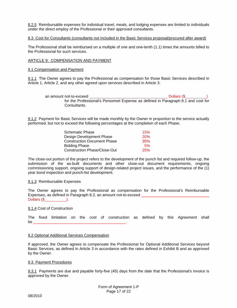
Form of Agreement 1-P Page 17 of 22
08/2010
8.2.5 Reimbursable expenses for individual travel, meals, and lodging expenses are limited to individuals under the direct employ of the Professional or their approved consultants. 8.3 Cost for Consultants (consultants not included in the Basic Services proposal/procured after award) The Professional shall be reimbursed on a multiple of one and one-tenth (1.1) times the amounts billed to the Professional for such services. ARTICLE 9: COMPENSATION AND PAYMENT 9.1 Compensation and Payment 9.1.1 The Owner agrees to pay the Professional as compensation for those Basic Services described in Article 1, Article 2, and any other agreed upon services described in Article 3: an amount not-to-exceed Dollars ($ )
for the Professional's Personnel Expense as defined in Paragraph 8.1 and cost for Consultants.
9.1.2 Payment for Basic Services will be made monthly by the Owner in proportion to the service actually performed, but not to exceed the following percentages at the completion of each Phase. Schematic Phase 15%
Design Development Phase 20% Construction Document Phase 35% Bidding Phase 5% Construction Phase/Close-Out 25%
The close-out portion of the project refers to the development of the punch list and required follow-up, the submission of the as-built documents and other close-out document requirements, ongoing commissioning support, ongoing support of design-related project issues, and the performance of the (1) year bond inspection and punch-list development. 9.1.3 Reimbursable Expenses The Owner agrees to pay the Professional as compensation for the Professional's Reimbursable Expenses, as defined in Paragraph 8.2, an amount not-to-exceed Dollars ($ ). 9.1.4 Cost of Construction The fixed limitation on the cost of construction as defined by this Agreement shall be . 9.2 Optional Additional Services Compensation If approved, the Owner agrees to compensate the Professional for Optional Additional Services beyond Basic Services, as defined in Article 3 in accordance with the rates defined in Exhibit B and as approved by the Owner. 9.3 Payment Procedures 9.3.1 Payments are due and payable forty-five (45) days from the date that the Professional's invoice is approved by the Owner.
Form of Agreement 1-P Page 18 of 22
08/2010
9.3.2 Submission of the Professional's invoice for final payment and reimbursement shall further constitute the Professional's representation to the Owner that, upon receipt from the Owner of the amount invoiced, all obligations of the Professional to others, including its consultants, incurred in connection with the Project will be paid in full. 9.3.3 Documentation accurately reflecting the time expended by the Professional and its personnel and records of Reimbursable Expenses shall be maintained by the Professional and shall be available to the Owner for review and copying upon request. 9.4 Owner’s Right to Withhold Payment In the event that the Owner becomes credibly informed that any representation of the Professional provided pursuant to Articles 8 or 9 is wholly or partially inaccurate, the Owner may withhold payment of sums then or in the future otherwise due to the Professional until the inaccuracy, and the cause thereof, is corrected to the Owner's reasonable satisfaction. ARTICLE 10: INSURANCE 10.1 Professional Liability Insurance The Professional shall secure and maintain, at its sole cost and expense, Professional Liability Insurance to protect against loss resulting from design errors and omissions, failure to coordinate the Construction Documents of the Project, and failure to execute the construction administration duties for the Project. 10.1.1 Unless otherwise specifically provided in this Agreement, the Professional shall secure and maintain Professional Liability Insurance with limits not less than $1,000,000, or the total of the Professional’s fee, whichever is greater. 10.1.2 The Professional shall secure and maintain Professional Liability Insurance, as required above, up to and including one year after the date of the (1) year guarantee inspection of the contracts under the Project.
10.2 General Liability Insurance The Professional shall secure and maintain, at its sole cost and expense, adequate General Liability Insurance to protect the Owner and the Owner's respective officers, agents, servants, and employees against claims arising out of the Professional's services during the design and construction of the Project for damages in law or equity for property damage and bodily injury, including wrongful death. The Owner shall be named as an additional insured in the policy, and the Professional shall submit a Certificate of Insurance to the Owner prior to execution of the Agreement. The limits of coverage shall be not less than $1,000,000, or the total of the Professional’s fee, whichever is greater. The Professional is required to secure and maintain General Liability Insurance, up to and including one year after the date of the (1) year guarantee inspection of the contracts under the Project. 10.3 Certificate of Insurance The Professional shall furnish to the Owner annually, unless otherwise requested, during the active terms of this Agreement, a Certificate from an Insurance Carrier authorized to do business in Pennsylvania indicating: (1) the existence of the insurance required under this Article; (2) the amount of the deductible; and (3) the amount of coverage of such insurance. The Professional shall submit a Certificate of Insurance covering the Professional Liability Insurance requirement up to and including one year after the date of the (1) year guarantee inspection of the contracts under the Project. 10.4 Failure to Comply with Insurance Requirements
Form of Agreement 1-P Page 19 of 22
08/2010
During any period in which the Professional is not in compliance with the terms of this Article, no compensation shall be paid by the Owner to the Professional. ARTICLE 11: TERMINATION, ABANDONMENT, SUSPENSION, REACTIVATION 11.1 Termination by Owner The Owner shall have the right at any time, for any reason, to terminate this Agreement upon not less than seven (7) calendar days' written notice to the Professional. The Professional shall comply with all reasonable instructions of the Owner then or subsequently given relating to such termination, including but not limited to: instructions concerning delivery of drawings, sketches, and other architectural/engineering data to the Owner; discontinuance of the work on outstanding contracts; and furnishing to the Owner information concerning all actions to be taken respecting outstanding agreements with consultants, contracts, awards, orders, or other matters. Copies of Construction Documents and any other materials in existence as of the date of termination will be furnished to the Owner as requested. 11.2 Compensation in the Event of Termination In the event of termination, the Professional shall be compensated for its services to the termination date based upon services performed on any Phase to the termination date in accordance with the Compensation and Payment schedule contained herein at Article 9.1.2. Such compensation shall be the Professional's sole and exclusive remedy for termination. 11.3 Suspension of Work The Owner may, at any time, direct the Professional to suspend all work on the Project, or on any part thereof, pending receipt of further notice from the Owner. In all such cases the Owner and the Professional shall agree upon an appropriate phasing-out of the work in such a manner that the work may be resumed with a minimum of added cost to the Owner, but in no event shall the work be continued beyond the completion of the portion of the project then in progress. The Professional shall be compensated as if the Agreement had been terminated at the completion of the agreed Phase. If work is suspended during the Construction Phase, compensation shall be paid for all Professional services provided to the date of suspension, but no additional compensation shall be paid during the period of suspension. 11.4 Reactivation Compensation When a Project has been suspended or terminated for a longer time than six (6) months and is subsequently reactivated using the same Professional, the Owner and the Professional shall agree, prior to the beginning of the reactivation work, upon a lump sum, or other basis, of reimbursement to the Professional for its extra start-up costs occasioned as a result of the work having been suspended or terminated. ARTICLE 12: MISCELLANEOUS PROVISIONS 12.1 Dispute Resolution / Applicable Law After Final Completion of the Project, any and all claims, disputes or controversies arising under, out of, or in connection with this Agreement, which the parties shall be unable to resolve within sixty (60) days of the time when the issue is first raised with the other party, shall be mediated in good faith. The party raising such dispute shall promptly advise the other party of such claim, dispute or controversy, in writing, describing in reasonable detail the nature of such dispute. By not later than five (5) business days after the recipient has received such notice of dispute, each party shall have selected for itself a representative who shall have the authority to bind such party, and shall additionally have advised the other party in
Form of Agreement 1-P Page 20 of 22
08/2010
writing of the name and title of such representative. By not later than ten (10) business days after the date of such notice of dispute, the parties shall mutually select a Pennsylvania-based mediator, and such representatives shall schedule a date for mediation, not to exceed one (1) day in length, and less where applicable. The mediation session shall take place on the University Park Campus of The Pennsylvania State University, or upon the campus where the Work was performed, at the option of the Owner. The parties shall enter into good faith mediation and shall share the costs equally. If the representatives of the parties have not been able to resolve the dispute within fifteen (15) business days after such mediation hearing, the parties shall have the right to pursue any other remedies legally available to resolve such dispute in the Court of Common Pleas of Centre County, Pennsylvania, jurisdiction to which the parties to this Agreement hereby irrevocably consent and submit. Notwithstanding the foregoing, nothing in this clause shall be construed to waive any rights or timely performance of any obligations existing under this Agreement. In all respects, this Agreement shall be interpreted and construed in accordance with the internal laws (and not the law of conflicts) of the Commonwealth of Pennsylvania. 12.2 Successors and Assigns This Agreement shall be binding on the successors and assigns of the parties hereto. 12.3 Assignment Neither the Owner nor the Professional shall assign, sublet, or in any manner transfer any right, duty, or obligation under this Agreement without prior written consent of the other party. 12.4 Extent of Agreement This Agreement, including any and all schedules, proposals and/or terms and conditions attached hereto, represent the entire and integrated agreement between the Owner and the Professional and supersedes all prior negotiations, representations, or agreements, either written or oral. This Agreement may be amended only by written instrument signed by both the Owner and the Professional. In the event of a conflict between the provisions of this Agreement and those of any other document, including any that are attached hereto, the provisions of this Agreement shall prevail. Furthermore, any provision, terms or conditions contained within any documents attached as exhibits hereto are void and lacking in any force or effect, with the exception of entries which define the Professional’s scope of work for the Project, Professional’s billable hourly rates, and project schedule. 12.5 Third Party Nothing contained in this Agreement shall create a contractual relationship with or a cause of action in favor of a third party against either the Owner or the Professional. 12.6 Hazardous Material Unless otherwise provided in this Agreement, the Professional and its consultants shall have no responsibility for the discovery, presence, handling, removal, or disposal of, or exposure of persons to hazardous materials in any form at the Project site, including but not limited to asbestos, asbestos products, polychlorinated biphenyl (PCB), or other toxic material. If the Professional encounters or suspects hazardous or toxic material, the Professional shall advise the Owner immediately.
Form of Agreement 1-P Page 21 of 22
08/2010
12.7 Promotional Material The Professional shall not issue or disclose to third parties any information relating to the Project without prior written consent of the Owner, except to the extent necessary to obtain necessary permits or governmental approvals, coordinate the Work with the Owner’s agent, Contractors, Subcontractors, etc. The Professional may, with written consent of the Owner, include design representation of the Project, including interior and exterior photographs, among the Professional's promotional and professional materials. 12.8 Terms/General Conditions Terms contained in this Agreement and which are not defined herein shall have the same meaning as those in the Owner's Form of Agreement between Owner and Contractor and the Owner's General Conditions of the Contract for Construction, current as of the date of this Agreement. ARTICLE 13: SCHEDULE OF EXHIBITS The attached Exhibits are part of this agreement: Exhibit A: Professional’s proposal dated ________________ NOTE: Professional’s proposal is attached solely for purposes of defining Professional’s scope of work. As per Article 12.4 of this Agreement, additional terms and conditions that may be included in the Professional’s proposal, beyond those relating to scope of work, are void, without effect, and not considered to be part of this Agreement. Exhibit B: Professional’s Billable Hourly Rates. Exhibit C: The Pennsylvania State University Design and Construction Standards listing (screen print from the Office of Physical Plant web page). Exhibit D: Project Schedule outlining design submission dates to be followed per Article 1, Section 1.1.9.
Form of Agreement 1-P Page 22 of 22
08/2010
THE PENNSYLVANIA STATE UNIVERSITY OWNER _________________________________ __________________________________ Title ATTEST, Secretary (PROFESSIONAL COMPANY NAME) PROFESSIONAL _________________________________ __________________________________ Title ATTEST, Secretary Attachments