Embed Size (px)
Citation preview
67C Series
D10
2601
X01
2
Instruction ManualForm 5469
May 2006
www.emersonprocess.com/regulators
R
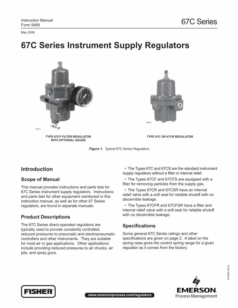
67C Series Instrument Supply Regulators
Type 67CF FIlTeR RegulaToR wITh opTIonal gauge
Type 67C oR 67CR RegulaToR
Figure 1. Typical 67C Series Regulators
W7412
W8438
Introduction
Scope of ManualThis manual provides instructions and parts lists for 67C Series instrument supply regulators. Instructions and parts lists for other equipment mentioned in this instruction manual, as well as for other 67 Series regulators, are found in separate manuals.
product DescriptionsThe 67C Series direct-operated regulators are typically used to provide constantly controlled, reduced pressures to pneumatic and electropneumatic controllers and other instruments. They are suitable for most air or gas applications. Other applications include providing reduced pressures to air chucks, air jets, and spray guns.
• The Types 67C and 67CS are the standard instrument supply regulators without a filter or internal relief. • The Types 67CF and 67CFS are equipped with a filter for removing particles from the supply gas. • The Types 67CR and 67CSR have an internal relief valve with a soft seat for reliable shutoff with no discernible leakage. • The Types 67CFR and 67CFSR have a filter and internal relief valve with a soft seat for reliable shutoff with no discernible leakage.
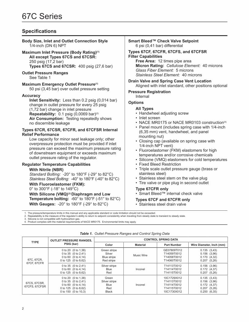
SpecificationsSome general 67C Series ratings and other specifications are given on page 2. A label on the spring case gives the control spring range for a given regulator as it comes from the factory.
67C Series
2
Specifications
Body Size, Inlet and outlet Connection Style 1/4-inch (DN 6) NPTMaximum Inlet pressure (Body Rating)(1) all except Types 67CS and 67CSR: 250 psig (17,2 bar) Types 67CS and 67CSR: 400 psig (27,6 bar)outlet pressure Ranges See Table 1Maximum emergency outlet pressure(1) 50 psi (3,45 bar) over outlet pressure settingaccuracy Inlet Sensitivity: Less than 0.2 psig (0,014 bar) change in outlet pressure for every 25 psig (1,72 bar) change in inlet pressure Repeatability: 0.1 psig (0,0069 bar)(2)
air Consumption: Testing repeatedly shows no discernible leakageTypes 67CR, 67CSR, 67CFR, and 67CFSR Internal Relief performance Low capacity for minor seat leakage only; other overpressure protection must be provided if inlet pressure can exceed the maximum pressure rating of downstream equipment or exceeds maximum outlet pressure rating of the regulator. Regulator Temperature Capabilities with nitrile (nBR) Standard Bolting: -20° to 180°F (-29° to 82°C) Stainless Steel Bolting: -40° to 180°F (-40° to 82°C) with Fluoroelastomer (FKM): 0° to 300°F (-18° to 149°C) with Silicone (VMQ)(3) Diaphragm and low Temperature bolting: -60° to 180°F (-51° to 82°C) with gauges: -20° to 180°F (-29° to 82°C)
Smart Bleed™ Check Valve Setpoint 6 psi (0,41 bar) differentialTypes 67CF, 67CFR, 67CFS, and 67CFSR Filter Capabilities Free area: 12 times pipe area Micron Rating: Cellulose Element: 40 microns Glass Fiber Element: 5 microns Stainless Steel Element: 40 micronsDrain Valve and Spring Case Vent location Aligned with inlet standard, other positions optionalpressure Registration Internaloptions all Types • Handwheel adjusting screw • Inlet screen • NACE MR0175 or NACE MR0103 construction(4)
• Panel mount (includes spring case with 1/4-inch (6,35 mm) vent, handwheel, and panel mounting nut) • Closing cap (available on spring case with 1/4-inch NPT vent) • Fluoroelastomer (FKM) elastomers for high temperatures and/or corrosive chemicals • Silicone (VMQ) elastomers for cold temperatures • Fixed Bleed Restriction • Triple scale outlet pressure gauge (brass or stainless steel) • Stainless steel stem on the valve plug • Tire valve or pipe plug in second outlet Type 67CFR only • Smart Bleed™ internal check valve Types 67CF and 67CFR only • Stainless steel drain valve
1. The pressure/temperature limits in this manual and any applicable standard or code limitation should not be exceeded. 2. Repeatability is the measure of the regulator’s ability to return to setpoint consistently when traveling from steady state to transient to steady state. 3. Silicone is not compatible with hydrocarbon gas. 4. Product complies with the material requirements of NACE MR0175. Environmental limits may apply.
Table 1. Outlet Pressure Ranges and Control Spring Data
Type ouTleT pReSSuRe RangeS, pSIg (bar)
ConTRol SpRIng DaTa
Color Material part number wire Diameter, Inch (mm)
67C, 67CR, 67CF, 67CFR
0 to 200 to 35 0 to 60
0 to 125
(0 to 1,38) (0 to 2,41) (0 to 4,14) (0 to 8,62)
Green stripeSilver
Blue stripeRed stripe
Music Wire
GE07809T012T14059T0012T14058T0012T14060T0012
0.1350.1560.1700.207
(3,43) (3,96) (4,32) (5,26)
0 to 35 0 to 60
0 to 125
(0 to 2,41) (0 to 4,14) (0 to 8,62)
Silver stripeBlueRed
InconelT14113T0012T14114T0012T14115T0012
0.1560.1720.207
(3,96) (4,37) (5,26)
67CS, 67CSR, 67CFS, 67CFSR
0 to 200 to 35 0 to 60
0 to 1250 to 150
(0 to 1,38) (0 to 2,41) (0 to 4,14) (0 to 8,62) (0 to 10,3)
GreenSilver stripe
BlueRed
Black
Inconel
10C1729X012T14113T0012T14114T0012T14115T001210C1730X012
0.1350.1560.1720.2070.250
(3,43) (3,96) (4,37) (5,26) (6,35)
67C Series
3
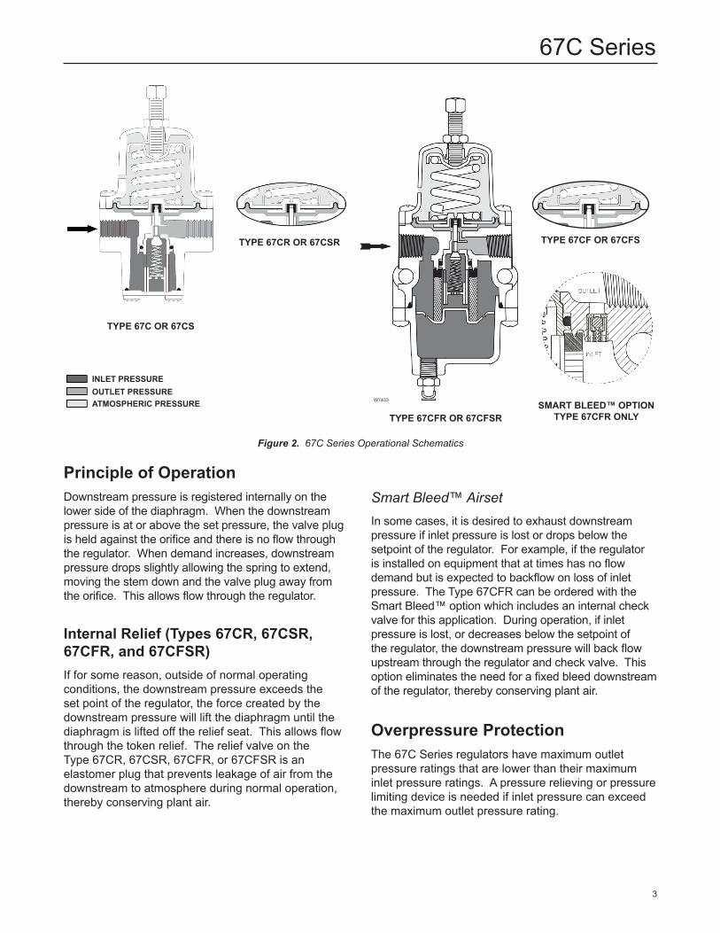
Type 67C oR 67CS
Type 67CR oR 67CSR
InleT pReSSuReouTleT pReSSuReaTMoSpheRIC pReSSuRe
Type 67CFR oR 67CFSRSMaRT BleeD™ opTIon
Type 67CFR only
W7433
Type 67CF oR 67CFS
Figure 2. 67C Series Operational Schematics
principle of operationDownstream pressure is registered internally on the lower side of the diaphragm. When the downstream pressure is at or above the set pressure, the valve plug is held against the orifice and there is no flow through the regulator. When demand increases, downstream pressure drops slightly allowing the spring to extend, moving the stem down and the valve plug away from the orifice. This allows flow through the regulator.
Internal Relief (Types 67CR, 67CSR, 67CFR, and 67CFSR)If for some reason, outside of normal operating conditions, the downstream pressure exceeds the set point of the regulator, the force created by the downstream pressure will lift the diaphragm until the diaphragm is lifted off the relief seat. This allows flow through the token relief. The relief valve on the Type 67CR, 67CSR, 67CFR, or 67CFSR is an elastomer plug that prevents leakage of air from the downstream to atmosphere during normal operation, thereby conserving plant air.
Smart Bleed™ AirsetIn some cases, it is desired to exhaust downstream pressure if inlet pressure is lost or drops below the setpoint of the regulator. For example, if the regulator is installed on equipment that at times has no flow demand but is expected to backflow on loss of inlet pressure. The Type 67CFR can be ordered with the Smart Bleed™ option which includes an internal check valve for this application. During operation, if inlet pressure is lost, or decreases below the setpoint of the regulator, the downstream pressure will back flow upstream through the regulator and check valve. This option eliminates the need for a fixed bleed downstream of the regulator, thereby conserving plant air.
overpressure protectionThe 67C Series regulators have maximum outlet pressure ratings that are lower than their maximum inlet pressure ratings. A pressure relieving or pressure limiting device is needed if inlet pressure can exceed the maximum outlet pressure rating.
67C Series
4
! waRnIng
! waRnIng
! waRnIng
gas service, vented gas may accumulate and cause personal injury, death, or property damage due to fire or explosion. Vent a regulator in hazardous gas service to a remote, safe location away from air intakes or any hazardous area. The vent line or stack opening must be protected against condensation or clogging.
Before installing a Type 67C, 67CR, 67CS, 67CSR, 67CF, 67CFR, 67CFS, or 67CFSR regulator, be sure the installation complies with the following installation guidelines:
1. Regulator operation within ratings does not preclude the possibility of damage from debris in the lines or from external sources. Regulators should be inspected for damage periodically and after any overpressure condition.
2. Only personnel qualified through training and experience should install, operate, and maintain a regulator. Make sure that there is no damage to or foreign material in the regulator. Also ensure that all tubing and piping is free of debris.
3. Install the regulator so that flow is from the IN to the OUT connection as marked on the regulator body.
4. For best drainage, orient the drain valve (key 2) to the lowest possible point on the dripwell (key 5). This orientation may be improved by rotating the dripwell with respect to the body (key 1).
5. A clogged spring case vent hole may cause the regulator to function improperly. To keep this vent hole from being plugged (and to keep the spring case from collecting moisture, corrosive chemicals, or other foreign material) orient the vent to the lowest possible point on the spring case or otherwise protect it.
Inspect the vent hole regularly to make sure it is not plugged. Spring case vent hole orientation may be changed by rotating the spring case with respect to the body. A 1/4-inch NPT spring case vent may be remotely vented by installing obstruction-free tubing or piping into the vent. Protect the remote vent by installing a screened vent cap on the remote end of the vent pipe.
6. For use in regulator shutdown, install upstream block and vent valves and downstream block and vent valves (if required), or provide some other suitable means of properly venting the regulator inlet and outlet pressures. Install a pressure gauge to monitor instruments on startup.
Types 67CR, 67CSR, 67CFR, 67CFSR have a low capacity internal relief valve for minor seat leakage only. Other overpressure protection must be provided if the maximum inlet pressure can exceed the maximum pressure rating of the downstream equipment or exceeds the maximum outlet pressure rating of the regulator.
Installation
note
If the regulator is shipped mounted on another unit, install that unit according to the appropriate instruction manual.
personal injury, property damage, equipment damage, or leakage due to escaping gas or bursting of pressure-containing parts may result if this regulator is overpressured or is installed where service conditions could exceed the limits given in the specifications, or where conditions exceed any ratings of the adjacent piping or piping connections. To avoid such injury or damage, provide pressure-relieving or pressure-limiting devices (as required by the appropriate code, regulation, or standard) to prevent service conditions from exceeding those limits.
The internal relief valve of the Type 67CR, 67CSR, 67CFR, or 67CFSR does not provide full overpressure protection. The internal relief valve is designed for minor seat leakage only. If maximum inlet pressure to the regulator exceeds maximum pressure ratings of the downstream equipment or exceeds maximum allowable outlet pressure of the regulator, additional overpressure protection is required.
a regulator may vent some gas to the atmosphere. In hazardous or flammable
67C Series
5
7. Apply a good grade of pipe compound to the male pipe threads before making connections, making sure not to get the pipe compound inside the regulator.
8. Install tubing fitting or piping into the 1/4-inch (DN 6) NPT inlet connection on the body (key 1) and into the 1/4-inch (DN 6) NPT body outlet connection.
9. The second 1/4-inch (DN 6) NPT outlet can be used for a gauge or other use. If not used, it must be plugged.
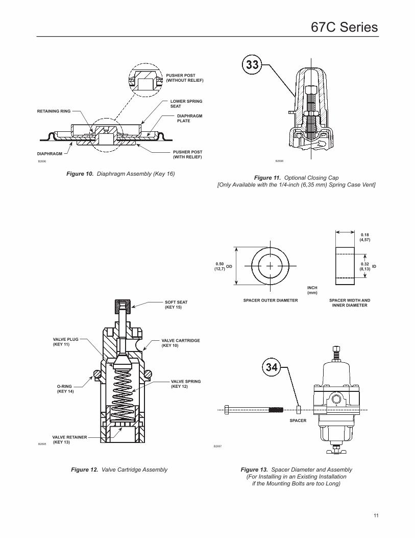
Installing a 67CF Series Regulator in an existing InstallationWhen installing a 67CF Series regulator in an existing installation, it may be necessary to use spacers (key 34, Figure 13) to adapt the installation. If the mounting bolts are too long, place a spacer on the bolt (see Figure 13). To be sure the regulator is secure, the bolts should have at least two full threads of engagement.
Startup and adjustmentKey numbers are referenced in Figures 3 through 9.
1. With proper installation completed and downstream equipment properly adjusted, slowly open the upstream and downstream shutoff valve (when used) while using pressure gauges to monitor pressure.
To avoid personal injury, property damage, or equipment damage caused by bursting of pressure containing parts or explosion of accumulated gas, never adjust the control spring to produce an outlet pressure higher than the upper limit of the outlet pressure range for that particular spring. If the desired outlet pressure is not within the range of the control spring, install a spring of the proper range according to the diaphragm parts maintenance procedure.
2. If outlet pressure adjustment is necessary, monitor outlet pressure with a gauge during the adjustment procedure. The regulator is adjusted by loosening the locknut (key 19), if used, and turning the adjusting screw or handwheel (key 18) clockwise to increase
! waRnIng
or counterclockwise to decrease the outlet pressure setting. Retighten the locknut to maintain the adjustment position.
ShutdownFirst, close the nearest upstream block valve and then close the nearest downstream block valve (when used). Next, open the downstream vent valve. Since the regulator remains open in response to the decreasing downstream pressure, pressure between the closed block valves will be released through the open vent valve.
MaintenanceRegulator parts are subject to normal wear and must be inspected and replaced as necessary. The frequency of inspection and replacement of parts depends on the severity of service conditions and applicable codes and government regulations. Open the Type 67CF, 67CFR, 67CFS, or 67CFSR drain valve (key 2) regularly to empty accumulated liquid from the dripwell (key 5).
note
If sufficient clearance exists, the body (key 1) may remain mounted on other equipment or in a line or panel during maintenance unless the entire regulator will be replaced.
To avoid personal injury, property damage, or equipment damage caused by sudden release of pressure or explosion of accumulated gas, do not attempt any maintenance or disassembly without first isolating the regulator from system pressure and relieving all internal pressure from the regulator.
Types 67C, 67CR, 67CS, and 67CSR
Trim Maintenance
Key numbers are referenced in Figures 3, 4, and 12.
1. Remove four bottom plate screws (key 3) from the bottom plate (key 39) and separate the bottom plate and O-ring (key 4) from the body (key 1).
! waRnIng
67C Series
6
2. Inspect the removed parts for damage and debris. Replace any damaged parts.
3. To remove the valve cartridge assembly, grasp the end of cartridge and pull it straight out of body (key 1). Replace with new cartridge assembly. The cartridge assembly may be disassembled and parts may be cleaned or replaced. If the soft seat (key 15) was removed, make sure it is properly snapped into place before installing the valve cartridge assembly.
4. Check O-ring (key 14) for wear and replace, if necessary. Apply lubricant to the O-ring and place in the body. Align cartridge key to keyway in body and insert. Reinstall the O-ring (key 4), secure the bottom plate (key 39) with screws (key 3), and torque to 15 to 30 inch-pounds (1,9 to 3,9 N•m).
Diaphragm MaintenanceKey numbers are referenced in Figures 3 and 4.
1. Back out the adjusting screw or handwheel (key 18) until compression is removed from the spring (key 17).
2. Remove the spring case screws (key 3) to separate the spring case (key 7) from the body (key 1). Remove the upper spring seat (key 20) and spring (key 17).
3. Remove the diaphragm assembly (key 16), inspect the diaphragm, and replace the assembly, if necessary.
4. Place the diaphragm assembly (key 16) on the body (key 1) as shown in Figure 3 or 4. Push down on the diaphragm assembly to make sure the valve plug (key 11) strokes smoothly and approximately 1/16-inch (1,59 mm).
note
In step 5, if installing a control spring of a different range, be sure to delete the spring range originally appearing on the label and indicate the new spring range.
5. Stack the control spring (key 17) and upper spring seat (key 20) onto the diaphragm assembly (key 16).
6. Install the spring case (key 7) on the body (key 1) with the vent oriented to prevent clogging or entrance of moisture. Install the six spring case screws (key 3) using a crisscross pattern and torque to 15 to 30 inch-pounds (1,9 to 3,9 N•m).
note
on Types 67CS and 67CSR, lubricate the adjusting screw (key 18) thread to reduce galling of the stainless steel.
7. When all maintenance is complete, refer to the Startup and Adjustment section to put the regulator back into operation and adjust the pressure setting. Tighten the locknut (key 19) if used, and install the closing cap (key 33) if used.
Types 67CF, 67CFR, 67CFS, and 67CFSR
Filter Element and Trim MaintenanceKey numbers are referenced in Figures 5, 6, and 12.
1. Remove four dripwell screws (key 3) from the dripwell (key 5) and separate the dripwell and O-ring (key 4) from the body (key 1). The filter retainer (key 9), thrust washer (key 37), filter element (key 6), and gasket (key 26) may come off with dripwell. If not, remove these parts.
2. Inspect the removed parts for damage and debris. Replace any damaged parts. If a replacement is not available, the filter element may be cleaned.
3. To remove the valve cartridge assembly, grasp the end of cartridge and pull it straight out of body (key 1). Replace with new cartridge assembly. The cartridge assembly may be disassembled and parts may be cleaned or replaced. If the soft seat (key 15) was removed, make sure it is properly snapped into place before installing the valve cartridge assembly.
4. Check O-ring (key 14) for wear and replace, if necessary. Apply lubricant to the O-ring (key 14), then align cartridge key to keyway in body and insert. Reinstall the gasket (key 26), filter element (key 6), thrust washer (key 37), and filter retainer (key 9). Reinstall the O-ring (key 4), secure the dripwell with screws (key 3), and torque to 15 to 30 inch-pounds (1,9 to 3,9 N•m).
Diaphragm Maintenance
Key numbers are referenced in Figures 5 and 6.
1. Back out the adjusting screw or handwheel (key 18) until compression is removed from the spring (key 17).
2. Remove the six spring case screws (key 3) to separate the spring case (key 7) from the body (key 1). Remove the upper spring seat (key 20) and spring (key 17).
3. Remove the diaphragm assembly (key 16), inspect the diaphragm, and replace the assembly, if necessary.
4. Place the diaphragm assembly (key 16) on the body (key 1) as shown in Figure 5. Push down on the
67C Series
7
diaphragm assembly to make sure the valve plug (key 11) strokes smoothly and approximately 1/16-inch (1,59 mm).
note
In step 5, if installing a control spring of a different range, be sure to delete the spring range originally appearing on the label and indicate the new spring range.
5. Stack the control spring (key 17) and upper spring seat (key 20) onto the diaphragm assembly (key 16).
6. Install the spring case (key 7) on the body (key 1) with the vent oriented to prevent clogging or entrance of moisture. Install the six spring case screws (key 3) using a crisscross pattern and torque to 15 to 30 inch-pounds (1,9 to 3,9 N•m).
note
on Types 67CFS and 67CFSR, lubricate the adjusting screw (key 18) thread to reduce galling of stainless steel.
7. When all maintenance is complete, refer to the Startup and Adjustment section to put the regulator back into operation and adjust the pressure setting. Tighten the locknut (key 19) if used, and install the closing cap (key 33) if used.
parts orderingWhen corresponding with the Fisher Sales Office or Sales Representative about this regulator, include the type number and all other pertinent information printed on the label. Specify the eleven-character part number when ordering new parts from the following parts list.
parts listKey Description part number
Parts Kits
Types 67C, 67CR, 67CS, and 67CSR - Includes valve cartridge assembly (contains keys 10, 11, 12, 13, 14, and 15), O-ring (key 4), diaphragm assembly (key 16), and four screws (key 3) Type 67C (without relief) Brass stem with nitrile plug R67CX000012 Aluminum stem with nitrile plug (NACE) R67CX000N12 Type 67CR (with relief) Brass stem with nitrile plug R67CRX00012 Aluminum stem with nitrile plug (NACE) R67CRX00N12 Type 67CS (without relief) Stainless steel stem with nitrile plug (NACE) R67CSX00012 Type 67CSR (with relief) Stainless steel stem with nitrile plug (NACE) R67CSRX0012
Key Description part number
Parts Kits (continued)
Types 67CF, 67CFR, and 67CFSR - Includes valve cartridge assembly (contains keys 10, 11, 12, 13, 14, and 15), diaphragm assembly (key 16), O-ring (key 4), filter element (key 6), filter gasket (key 26), thrust washer (key 37), and four screws (key 3) Type 67CF (without relief) Brass stem with nitrile plug R67CFX00012 Aluminum stem with nitrile plug (NACE) R67CFX00N12 Type 67CFR (with relief) Brass stem with nitrile plug R67CFRX0012 Aluminum stem with nitrile plug (NACE) R67CFRX0N12 Type 67CFSR (with relief) Stainless steel stem with nitrile plug (NACE) R67CFSRX012
Valve Cartridge assembly only(2)
Type 67C, 67CR, 67CF, or 67CFR Brass stem With nitrile plug T14121T0012 With fluoroelastomer plug T14121T0022 Aluminum stem with nitrile plug T14121T0042 with nitrile plug (NACE) T14121T0052
Type 67CS, 67CSR, 67CFS, or 67CFSR 316 Stainless steel stem with nitrile plug and O-rings (NACE) T14121T0092 with Fluoroelastomer plug and O-rings T14121T0102 with nitrile plug and Silicone O-rings T14121T0112
1 Body Type 67C or 67CR, Aluminum T40643T0RG2 Type 67CS or 67CSR, Stainless Steel GE00909X012 Type 67CF or 67CFR, Aluminum T80432T0012 Type 67CFS or 67CFSR, Stainless steel 40C1887X012 Type 67CFR with Smart Bleed™, Aluminum GE03477X012
2 Drain Valve Type 67CF or 67CFR Brass 1K418918992 18-8 Stainless steel AH3946X0012 Type 67CFS or 67CFSR 316 Stainless steel AH3946X0032
3 Flange Screw Type 67C, 67CR, 67CF, or 67CFR Standard spring case and spring case with 1/4-inch NPT vent (10 required) T13526T0012 For wire seal Flange Screw (9 required) T13526T0012 Flange Screw (1 required) 14B3987X012 Type 67CS, 67CSR, 67CFS or 67CFSR (10 required) T13526T0042
4(1) O-Ring Type 67C, 67CR, 67CS, or 67CSR Nitrile (NBR) T14380T0012 Fluoroelastomer (FKM) T14380T0022 Silicone (VMQ) T14380T0032 Type 67CF, 67CFR, 67CFS, or 67CFSR Nitrile (NBR) T14057T0012 Fluoroelastomer (FKM) T14057T0022 Silicone (VMQ) T14057T0032
5 Dripwell Type 67CF or 67CFR T21040T0012 Type 67CFS or 67CFSR 20C1726X012
6(1) Filter Element (Types 67CF, 67CFR, 67CFS, 67CFSR) Cellulose (40 microns) (Types 67CF, 67CFR Standard) 1F257706992 Glass fiber (5 microns) 17A1457X012 Stainless steel (40 microns) (Types 67CFS, 67CFSR Standard) 15A5967X022
1. Recommended Spare Part 2. Valve cartridge assembly includes keys 10, 11, 12, 13, 14, and 15.
67C Series
8
Key Description part number
7 Spring Case Type 67C, 67CR, 67CF, or 67CFR, Aluminum Drilled hole vent (standard) T14070T0012 1/4-inch NPT vent T14070T0022 Type 67CS, 67CSR, 67CFS, or 67CFSR, Stainless steel 20C1727X0129 Filter Retainer Type 67CF or 67CFR T14052T0012 Type 67CFS or 67CFSR T14052T0022 10(1, 2) Valve Cartridge T80434T0012
11(1, 2) Valve Plug Type 67C, 67CR, 67CF, or 67CFR Brass stem, Nitrile plug T14053T0012 Aluminum stem, Fluoroelastomer plug T14053T0022 Aluminum stem, Nitrile plug T14053T0032 Type 67CS, 67CSR, 67CFS, or 67CFSR Stainless steel stem, Nitrile plug T14053T0042 Stainless steel stem, Fluoroelastomer plug T14053T005212(1, 2) Valve Spring Type 67C, 67CR, 67CF, or 67CFR Stainless steel T14105T0012 Inconel (NACE) T14116T0012 Type 67CS, 67CSR, 67CFS, or 67CFSR, Inconel (NACE) T14116T001213(1, 2) Valve Retainer T14071T001214(1, 2) O-Ring Nitrile (NBR) T14063T0012 Fluoroelastomer (FKM) T14063T0022 Silicone (VMQ) T14063T003215(1, 2) Soft Seat Nitrile (NBR) T14055T0012 Fluoroelastomer (FKM) T14055T002216(1) Diaphragm Assembly Type 67C or 67CF (without relief) Nitrile (NBR) T14119T0022 Fluoroelastomer (FKM) T14119T0042 Type 67CR or 67CFR (with relief) Nitrile (NBR) T14119T0012 Fluoroelastomer (FKM) T14119T0032 Silicone (VMQ) T14119T0052 Type 67CS or 67CFS (without relief) Nitrile (NBR) T14119T0062 Fluoroelastomer (FKM) T14119T0072 Type 67CSR or 67CFSR (with relief) Nitrile (NBR) T14119T0082 Fluoroelastomer (FKM) T14119T0092 Silicone (VMQ) T14119T0102
17 Spring Type 67C, 67CR, 67CF, or 67CFR, Plated steel (standard) 0 to 20 psig (0 to 1,38 bar), Green stripe GE07809T012 0 to 35 psig (0 to 2,41 bar), Silver T14059T0012 0 to 60 psig (0 to 4,14 bar), Blue stripe T14058T0012 0 to 125 psig (0 to 8,62 bar), Red stripe T14060T0012 Type 67CR or 67CFR (NACE), Inconel (NACE) 0 to 35 psig (0 to 2,41 bar), Silver stripe T14113T0012 0 to 60 psig (0 to 4,14 bar), Blue T14114T0012 0 to 125 psig (0 to 8,62 bar), Red T14115T0012 Type 67CS, 67CSR, 67CFS or 67CFSR, Inconel (NACE) 0 to 20 psig (0 to 1,38 bar), Green 10C1729X012 0 to 35 psig (0 to 2,41 bar), Silver stripe T14113T0012 0 to 60 psig (0 to 4,14 bar), Blue T14114T0012 0 to 125 psig (0 to 8,62 bar), Red T14115T0012 0 to 150 psig (0 to 10,3 bar), Black 10C1730X012
Key Description part number
18 Adjusting Screw Type 67C, 67CR, 67CF, or 67CFR For standard spring case Square head (standard) T14061T0012 Handwheel T14102T0012 Wire seal (not shown) T14104T0012 For spring case with 1/4-inch NPT vent Square head for closing cap T14101T0012 Handwheel T14103T0012 Wire seal (not shown) T14198T0012
Type 67CS, 67CSR, 67CFS, or 67CFSR Square head with or without closing cap T14101T0022 Handwheel T14103T0012
19 Locknut Type 67C, 67CR, 67CF, or 67CFR 1A946324122 Type 67CS, 67CSR, 67CFS, or 67CFSR 1A9463X0042
20 Upper Spring Seat Type 67C, 67CR, 67CF, or 67CFR T14051T0012 Type 67CS, 67CSR, 67CFS, or 67CFSR 10C1725X012
22 Pressure Gauge (not shown) Brass 0 to 30 psig/0 to 2 bar/0 to 0,2 MPa 11B8579X022 0 to 60 psig/0 to 4 bar/0 to 0,4 MPa 11B8579X032 0 to 160 psig/0 to 11 bar/0 to 1,1 MPa 11B8579X042 Stainless Steel 0 to 30 psig/0 to 2 bar/0 to 0,2 MPa 11B9639X012 0 to 60 psig/0 to 4 bar/0 to 0,4 MPa 11B9639X022 0 to 160 psig/0 to 11 bar/0 to 1,1 MPa 11B9639X032
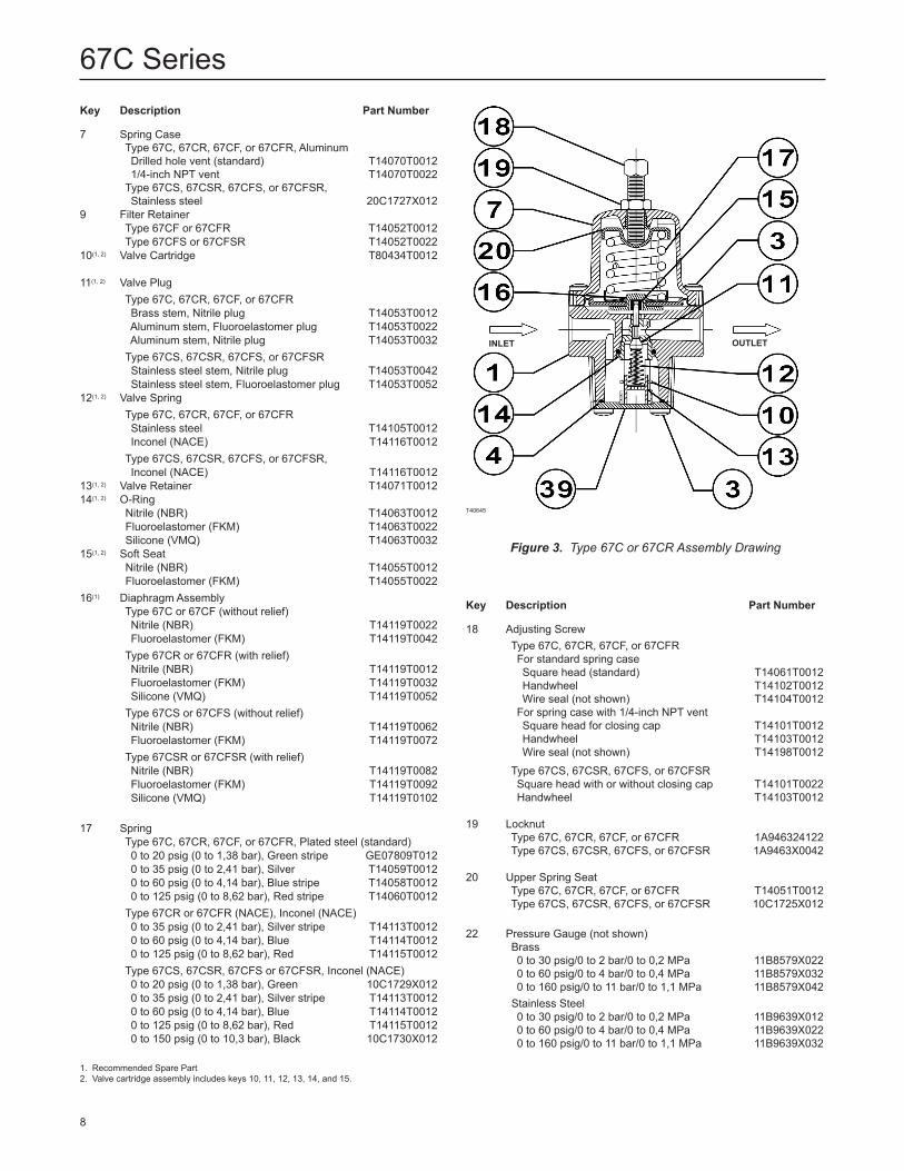
Figure 3. Type 67C or 67CR Assembly Drawing
T40645
InleT ouTleT
1. Recommended Spare Part 2. Valve cartridge assembly includes keys 10, 11, 12, 13, 14, and 15.
67C Series
9
Key Description part number
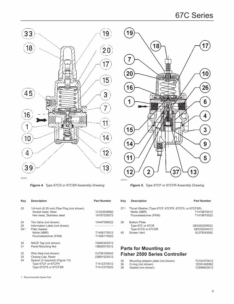
23 1/4-Inch (6,35 mm) Pipe Plug (not shown) Socket head, Steel 1C333528992 Hex head, Stainless steel 1A767535072
24 Tire Valve (not shown) 1H44709902225 Information Label (not shown) - - - - - - - - - - -26(1) Filter Gasket Nitrile (NBR) T14081T0012 Fluoroelastomer (FKM) T14081T0022
30 NACE Tag (not shown) 19A6034X01231 Panel Mounting Nut 10B2657X012
32 Wire Seal (not shown) 1U7581000A233 Closing Cap, Resin 23B9152X01234 Spacer (2 required) (Figure 13) Type 67CF or 67CFR T14123T0012 Type 67CFS or 67CFSR T14123T0022
Key Description part number
37(1) Thrust Washer (Type 67CF, 67CFR, 67CFS, or 67CFSR) Nitrile (NBR) T14196T0012 Fluoroelastomer (FKM) T14196T0022
39 Bottom Plate Type 67C or 67CR GE03520XRG2 Type 67CS or 67CSR GE03520X01245 Screen Vent 0L078343062
parts for Mounting on Fisher 2500 Series Controller35 Mounting adaptor plate (not shown) T21043T001236 O-ring (not shown) 1E59140699238 Gasket (not shown) 1C898603012
Figure 4. Type 67CS or 67CSR Assembly Drawing
GE03521
Figure 5. Type 67CF or 67CFR Assembly Drawing
T40573-2
1. Recommended Spare Part
67C Series
10
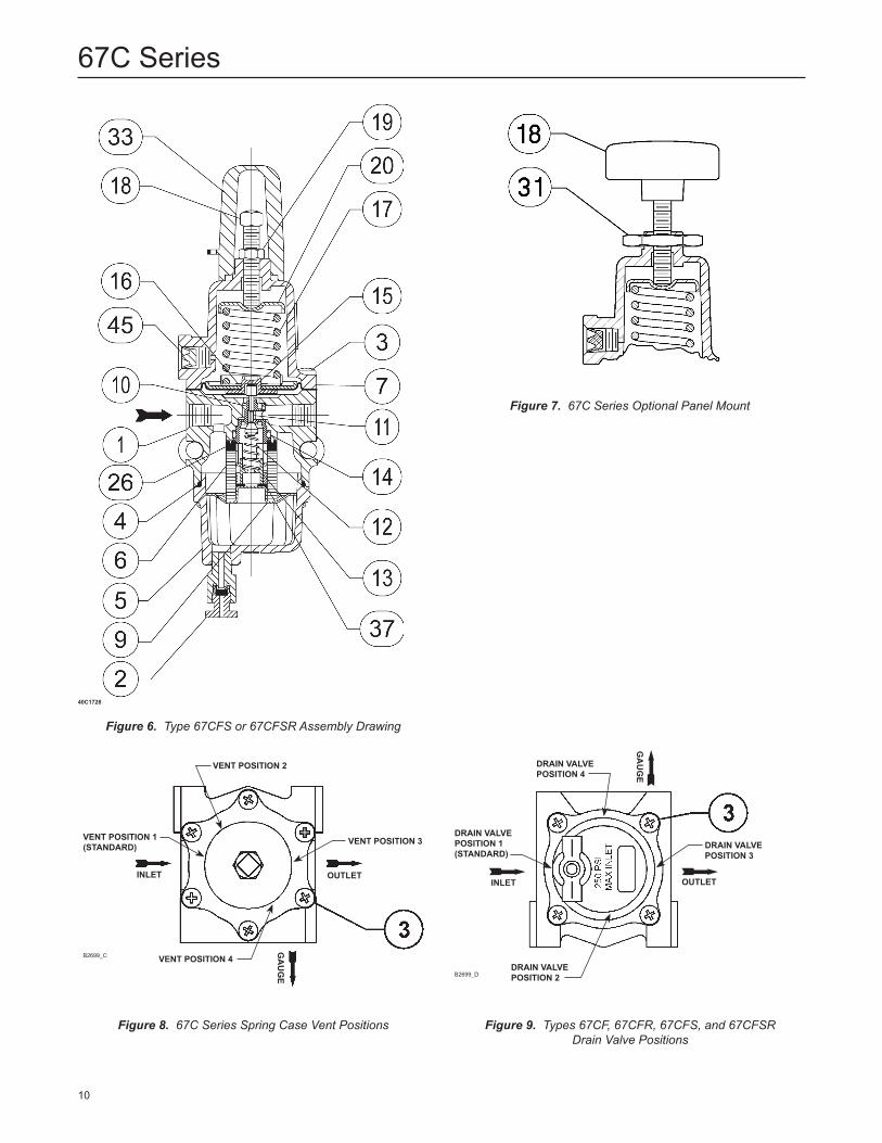
Figure 7. 67C Series Optional Panel Mount
Figure 6. Type 67CFS or 67CFSR Assembly Drawing
40C1728
Figure 8. 67C Series Spring Case Vent Positions
VenT poSITIon 1 (STanDaRD)
InleT ouTleT
VenT poSITIon 2
VenT poSITIon 4
VenT poSITIon 3
ga
ug
e
B2699_C
DRaIn ValVe poSITIon 1(STanDaRD)
InleT ouTleT
ga
ug
e
DRaIn ValVe poSITIon 2
DRaIn ValVe poSITIon 4
DRaIn ValVe poSITIon 3
B2699_D
Figure 9. Types 67CF, 67CFR, 67CFS, and 67CFSR Drain Valve Positions
67C Series
11
Figure 11. Optional Closing Cap[Only Available with the 1/4-inch (6,35 mm) Spring Case Vent]
B2698
Figure 12. Valve Cartridge Assembly Figure 13. Spacer Diameter and Assembly(For Installing in an Existing Installation
if the Mounting Bolts are too Long)
SpaCeR
B2697
SpaCeR ouTeR DIaMeTeR SpaCeR wIDTh anDInneR DIaMeTeR
0.32(8,13)
0.18(4,57)
0.50(12,7) IDoD
SoFT SeaT(Key 15)
ValVe CaRTRIDge(Key 10)
ValVe SpRIng(Key 12)
ValVe plug(Key 11)
o-RIng(Key 14)
ValVe ReTaIneR (Key 13)B2695
ReTaInIng RIng
puSheR poST(wIThouT RelIeF)
loweR SpRIngSeaT
DIaphRagMplaTe
puSheR poST(wITh RelIeF)
DIaphRagM
Figure 10. Diaphragm Assembly (Key 16)
B2696
InCh(mm)
67C Series
The Emerson logo is a trademark and service mark of Emerson Electric Co. All other marks are the property of their prospective owners. Fisher is a mark owned by Fisher Controls, Inc., a business of Emerson Process Management.
The contents of this publication are presented for informational purposes only, and while every effort has been made to ensure their accuracy, they are not to be construed as warranties or guarantees, express or implied, regarding the products or services described herein or their use or applicability. We reserve the right to modify or improve the designs or specifications of such products at any time without notice.
Emerson Process Management does not assume responsibility for the selection, use or maintenance of any product. Responsibility for proper selection, use and maintenance of any Emerson Process Management product remains solely with the purchaser.
©Fisher Controls International, Inc., 2003, 2006; All Rights Reserved
Industrial
USA - HeadquartersMcKinney, Texas 75070 USATel: 1-800-558-5856Outside U.S. 1-469-293-4201
Asia-PacificShanghai, China 201206Tel: 86-21-5899 7887
EuropeBologna, Italy 40013Tel: 39 051 4190611
natural gas Technologies
USA - HeadquartersMcKinney, Texas 75070Tel: 1-800-558-5856Outside U.S. 1-469-293-4201
Asia-PacificSingapore, Singapore 128461Tel: +65 6777 8211
EuropeBologna, Italy 40013Tel: 39 051 4190611Gallardon, France 28320Tel: +33 (0)2 37 33 47 00
Industrial/high purity
TESCOMElk River, Minnesota 55330 USATel: 1-763-241-3238Selmsdorf, Germany 23923Tel: +49 (0) 38823 31 0
For further information visit www.emersonprocess.com/regulators