Embed Size (px)
Citation preview

Part Number 16601 Rev. B May 2011 Page 1
INSTALLATION, OPERATION AND MAINTENANCE MANUAL
No. 16601 Revision B
May 2011
SafetyNet
VEHICLE FIRE SUPPRESSION SYSTEM CONTROL COMPONENTS
Amerex Corporation
Post Office Box 81 – 7595 Gadsden Highway Trussville, Alabama 35173-0081
Phone: (205) 655-3271 Fax: (205) 655-3279 Email: [email protected]
Home Page: http://www.amerex-fire.com

Part Number 16601 Rev. B May 2011 Page 2
Part Number 16601 Rev. B May 2011 Page 3
Amerex SafetyNet Instruction Manual
SafetyNet Table of Contents
1 Introduction to Amerex Vehicle SafetyNet
Introduction SafetyNet Benefits SafetyNet Features
2 SafetyNet System Components
Operator Display Driver Panel Detection Module Actuation Module Detection & Actuation Module SafeIR Optical Flame Detector
3 Hazard Analysis
Identifying the Potential for Fire Assessing the Consequences of Fire Determining the Need for Fire Protection Selecting the Appropriate Fire Suppression Options Selecting Fire Suppression System Hardware
4 SafetyNet Installation
Considerations before installing SafetyNet SafetyNet Module Installation Considerations SafeIR Optical Flame Sensor Installation Considerations
AMGaDS Combustible Gas Sensor Installation Considerations
5 SafetyNet Use
Self-Configuration Configuration Confirmation Push to Test Button System Reconfiguration
6 SafetyNet Applications
Fire Suppression & Four Gas Detection Zones Fire Suppression, Multiple Gas Detection and Optical Flame Detection Multiple Zone Gas Detection Application Multiple Fire Suppression Release Zones
7 SafetyNet Maintenance
System Module Maintenance SafeIR Sensor Maintenance AMGaDS Sensor Maintenance
8 Appendix
SafetyNet Event Log Message Table Event Definitions SafetyNet Part Number List Agency Approval Standards

Part Number 16601 Rev. B May 2011 Page 4
1 Introduction to Amerex Vehicle SafetyNet
1.1 Introduction
The Amerex Vehicle SafetyNet System (AVSN) is a natural evolution of the Amerex AMGaDS Mobile Gas Detection System and the Modular Fire Suppression System electronic control system. The SafetyNet System consists of a self-configuring, proprietary, microprocessor based Vehicle Safety Network that gives added flexibility to the proven Amerex Vehicle System Design. Modular components allow for custom tailored Fire Suppression and Gas Detection Applications.
Simplicity, Flexibility and Reliability are key features of the SafetyNet System. The SafetyNet System automatically recognizes other SafetyNet components and self configures for proper operation. For the intermediate user needing additional system flexibility, SafetyNet offers easy to use Windows based pull-down menu screens for application specific programming. A more advanced feature of SafetyNet allows the user to gather data in real-time from system sensors (event / data logging). The Amerex Vehicle SafetyNet has been tested to FM, SAE, and CE standards and is the next step in Vehicle Fire Suppression Safety.
1.2 SafetyNet Benefits:
Simplified System Messaging
Simplified System Troubleshooting
Simple programming features allow for design flexibility
Event Data Recording with Time and Date Stamp
Provides Fire Suppression and Gas Detection capability from –40 F to +158 F
Multiple Sensor Input Types Spot Heat Sensors AMGaDS III Combustible Gas Sensors Linear Heat Detection Analog Heat Sensors SafeIR Optical Flame Sensors
Uses existing AMGaDS III Cables
Easy Installation & Maintenance
Allows for Delayed System Release, Multiple Cylinder Release, and Second Shot Release
Zoned Heat Detection Zoned Fire Protection Fire Warning System
Can be used for Overheat Early Warning and Temperature Monitoring

Part Number 16601 Rev. B May 2011 Page 5
1.3 SafetyNet Features:
Event Logging (4000+ events)
Data Monitor and Logging Mode
Internal Audible Alarm with Silence
Trouble Indications for all inputs and outputs
Trouble ring back feature
Relay Output for Fire, Gas and Trouble conditions
Relay Override/Reset Switch
System self test function
Remote programming via laptop computer (RS-232 or USB interface)
Environmentally sealed enclosures
Easy to read Vacuum Fluorescent Display (VFD)
Basic system status via LED indication
Ability to implement multiple language text messages
Network interface to other SafetyNet Modules via existing AMGaDs III Cables
Provides event indication via VFD
Multiple detection and releasing zones
Timed releasing circuits
Detection inputs include Optical Flame Detection, Spot Heat Detection, Resistance Temperature Device (RTD) Analog Input Heat Detection, AMGaDS III Gas Detection
Wide operating temperature range
Backwardly compatible with all existing Amerex AMGaDS III and Modular System wiring.
Rugged compact design
10.5 to 30 VDC Operation
Fire Suppression System hardware, such as agent cylinders, mounting brackets, hoses, nozzles, complete system design, installation, maintenance, and recharge of the fire suppression system and replacement parts are not covered in this manual. The SafetyNet components described herein are combined with these other components to complete the design and installation of a vehicle fire suppression system and/or methane detection system. Please refer to the following Amerex manuals for additional information: P/N 13980: Installation, Operation and Maintenance of Modular Dry Chemical Vehicle Fire Suppression Systems using Electric Valve Actuation for Models V13, V25, VH25 and V50. P/N 16400: Installation, Operation and Maintenance of Modular Dry Chemical Vehicle Fire Suppression Systems using Pneumatic Valve Actuation for Models V13, V25, VH25 and V50. P/N 14475: Owner’s Manual AMGaDS III Four Zone Fire Suppression and Methane Detection System. These manuals and addition information are available from:
Amerex Corporation, P.O. Box 81 7595 Gadsden Highway
Trussville, Al 35173 Phone: 205-655-3271, Fax: 205-655-3279
Email: [email protected] Home Page: http://www.amerex-fire.com

Part Number 16601 Rev. B May 2011 Page 6
2 SafetyNet System Components
Part No. 16389 Vehicle SafetyNet Operator Display (Item 1):
The Amerex Vehicle SafetyNet (AVSN) Operator Interface Panel indicates vehicle fire suppression system status to the vehicle operator or maintenance personnel. Basic system status is indicated via easy to read LEDs and audible alarm indications. Detailed “Event” text messages are shown on the panel display. The Operator Interface Panel functions as the AVSN central control. While each AVSN module is intelligent and capable of independent operation, the Operator Interface Panel coordinates all communication between all modules used. Programming is not necessary. However specialized programming can be performed off-line via a personal computer then transferred into the Operator Interface via the network RS-485 connection if specialized functions are desired. A Fire Suppression System only Operator Display P/N 17422 is also available which does not have the Gas Concentration LED functions.

Part Number 16601 Rev. B May 2011 Page 7
The P/N 16389 SafetyNet Operator Display connects to other SafetyNet Modules via standard AMGaDS III four wire sensor cables ordered separately. Select from available lengths in Wiring Harness Section on page 17.

Part Number 16601 Rev. B May 2011 Page 8
Part No. 16390 Vehicle SafetyNet Driver Panel (Item 2):
The Amerex Vehicle SafetyNet (AVSN) Driver Panel includes the most common features required for vehicle fire protection and gas detection systems. The Driver Panel is virtually identical to the AMGaDS III Driver Panel (P/N 14464) design. The AVSN Driver provides a connecting point for fire suppression/gas detection field wiring inputs and outputs. Connections are provided for System Power, Fire Suppression Actuation, Spot Heat Detection Zones, Manual Actuation, Agent Cylinder Pressure Supervision, Relay Contacts (Fire, Gas, Trouble), four zones of Gas or Flame Detection and AVSN connectivity. While the Driver Panel includes most system features, the network capability of the AVSN system allows for the addition of other specific system modules. The AVSN Driver panel includes battery backup for up to 24-hours of fire suppression capability in the event of system power failure. The AVSN Driver panel includes sensor recognition software. Using this software, the Driver Panel is able to automatically identify and differentiate AMGaDS III Gas Sensors, Safe-IR Optical Flame, Discrete/Analog Heat Sensors or Spot Heat Sensors. Sensor alarm warning is provided to the Operator Display Panel via a network cable. In the event of network failure, the Driver Panel contains default operating software, which allows the module to continue operation. Multiple Driver Panels may be used in a SafetyNet system if necessary.

Part Number 16601 Rev. B May 2011 Page 9
Modular Lead Assemblies are provided with the P/N 16390 Driver Panel for connection to DC power input (color coded red), electric actuation (color coded yellow), two detection circuits for spot heat sensors (color coded green), agent cylinder pressure switch monitor (color coded blue) and three SPDT relay outputs for fire alarm, gas detection and trouble conditions. Replacement Cord Sets are available as P/N 14840.
The Driver Panel connects to the Display Panel, additional SafetyNet Modules, SafeIR Optical Flame Detectors and AMGaDS III Methane Sensors using standard AMGaDS III four wire sensor cables ordered separately. Select from available lengths in Wiring Harness Section on page 17.

Part Number 16601 Rev. B May 2011 Page 10
Part No. 16391 Vehicle SafetyNet Detection Module (Item 3):
The P/N 16391 Detection Module allows for zoned Fire, Heat or Gas detection capability. The Detection Module can interface to AMGaDS III Gas Sensors, SafeIR Optical Flame Detectors, RTD Heat Sensors and Spot Heat Detectors. Any mix of detection types is acceptable. The Detection Module is able to automatically identify and discriminate between AMGaDS III Gas Sensors, Safe-IR Optical Flame, Discrete/Analog Heat Sensors and Spot Heat Sensors. Sensor alarm warning is provided to the Operator Display Panel via a network cable. All system sensors are monitored for proper operation. Detection of a Fire or Gas condition transfers an on-board relay. Depending upon the application, the relay may be wired into the vehicle engine shutdown circuit or other warning system. Network capability is built into the Detection Module allowing connection of multiple SafetyNet modules. More than one Detection Module may be used in a SafetyNet system as necessary.

Part Number 16601 Rev. B May 2011 Page 11
A modular lead assembly is provided with the P/N 16391 Detection Module for connection to DC power input (color coded red) and relay connection circuits. Replacement power/relay lead assemblies are available as P/N 16611. If DC power is to be supplied to the Detection Module, a Modular Power Supply Lead is required. Select a Power Lead from available lengths in Wiring Harness Section on page 17. If power is supplied from another SafetyNet Module, the power connection plug will remain unused. The Detection Module connects to additional SafetyNet Modules, SafeIR Optical Flame Detectors, RTD Heat Detectors and AMGaDS III Methane Sensors using standard AMGaDS III four wire sensor cables ordered separately. Select from available lengths in Wiring Harness Section on page 17. Connection of Spot Heat Sensors requires the use of one Spot Sensor Interface Cable P/N 16610 per circuit to connect to detection zones 1 through 4 on the Detection module. No interface cable is required for Gas Sensors, SafeIR Optical Sensors or RTD Heat Sensors.

Part Number 16601 Rev. B May 2011 Page 12
Part No. 16392 Vehicle SafetyNet Releasing Module (Item 4):
The P/N 16392 Releasing Module allows for zoned fire system agent cylinder actuation capability. The Releasing Module will support up to (4) separate Amerex Agent Cylinders. Agent Cylinder release timing can be programmed to occur immediately upon fire recognition, sequentially timed, or upon other external inputs. This module is capable of releasing cylinders using different Fire Suppression Agents. More than one Releasing Module may be used in a SafetyNet system. Separate connections are available for monitoring the pressure of each Agent Cylinder through the Agent Cylinder Pressure Switch. Release of any agent cylinder triggers an on-board relay. Depending upon the application, the relay may be wired into the vehicle engine shutdown circuit or other warning system.

Part Number 16601 Rev. B May 2011 Page 13
A modular lead assembly is provided with the P/N 16392 Releasing Module for connection to DC power input (color coded red) and relay connection circuits. Replacement power/relay lead assemblies are available as P/N 16611. If DC power is to be supplied to the Detection Module, a Modular Power Supply Lead is required. Select a Power Lead from available lengths in Wiring Harness Section on pages 17. If power is supplied from another SafetyNet Module, the power connection plug will remain unused. Four Modular Lead Assemblies are also provided with the Releasing Module for connection to the actuation leads (color coded yellow) and the agent cylinder pressure switch circuits (color coded blue) as needed. Replacement actuation/pressure switch lead assemblies are available as P/N 16612. The Releasing Module can connect to additional SafetyNet Modules using standard AMGaDS III four wire sensor cables ordered separately. Select from available lengths in Wiring Harness Section on page 17.

Part Number 16601 Rev. B May 2011 Page 14
Part No. 16395 Vehicle SafetyNet Detection and Releasing Module (Item 5):
The P/N 16395 Detection-Releasing Module allows for zoned fire detection and releasing capability. The Detection-Releasing Module provides an interface for AMGaDS III Gas Sensors, SafeIR Optical Flame Detectors, RTD Heat Sensors and Spot Heat Detectors. Any mix of detection types is acceptable. The Detection-Releasing Module is able to automatically identify and discriminate between AMGaDS III Gas Sensors, Safe-IR Optical Flame, Discrete/Analog RTD Heat Sensors and Spot Heat Sensors. Sensor warning is provided to the Operator Display Panel via a network cable. All system sensors are monitored for proper operation. Detection of a Fire or Gas condition transfers an on-board relay. Depending upon the application, the relay may be wired into the vehicle engine shutdown circuit or other warning system. Network capability allows for connection of multiple SafetyNet modules. More than one Detection-Releasing Module may be used in a SafetyNet system. The AVSN Detection-Releasing Module includes sensor recognition software. Default operation settings are programmed into this module releasing only the fire suppression system cylinders connected to this module. A second agent cylinder can be programmed to release upon an additional fire condition or a timed release. This module is capable of releasing cylinders using different Fire Suppression Agents as necessary. A separate connection is available for Agent Cylinder pressure monitoring.

Part Number 16601 Rev. B May 2011 Page 15
A modular lead assembly is provided with the P/N 16395 Detection-Release Module for connection to DC power input (color coded red) and relay connection circuits. Replacement power/relay lead assemblies are available as P/N 16611. If DC power is to be supplied to the Detection-Release Module, a Modular Power Supply Lead is required. Select a Power Lead from available lengths in Wiring Harness Section on Pages 17 through 19. If power is supplied from another SafetyNet Module, the power connection plug will remain unused. Two modular lead assemblies are also provided with the Detection-Releasing Module for connection to the actuation leads (color coded yellow) and the agent cylinder pressure switch circuits (color coded blue) as needed. Replacement actuation/pressure switch leads are available as P/N 16612. The Detection Module connects to additional SafetyNet Modules, SafeIR Optical Flame Detectors, RTD Heat Detectors and AMGaDS III Methane Sensors using standard AMGaDS III four wire sensor cables ordered separately. Select from available lengths in Wiring Harness Section on page 17.
Connection of Spot Heat Sensors requires the use of one Spot Sensor Interface Cable P/N 16610 per circuit to connect to detection zones 1 through 4 on the Detection module.

Part Number 16601 Rev. B May 2011 Page 16
Part No. 15799 SafeIR Optical Flame Detector (Item 6):
The P/N 15799 SafeIR Optical Flame Sensor is designed specifically for rapid response flame detection in under-hood, vehicle applications. The sensor operates by detecting CO2 emissions from a hydrocarbon fire. The Infrared wavelength of CO2 and the specific characteristics of a hydrocarbon fire allow the SafeIR sensor to discriminate against background noise and other hot bodies common in vehicle engine compartments. The detection range of the Safe-IR system is a ratio function of the sensor field of view vs the emitted energy created by a fire condition. That is, as the field of view is increased (i.e. distance from the lens increases) the size of the fire to be detected must also increase in order to maintain constant detection sensitivity. The characteristics of a Fire condition are differentiated from other signals commonly found in an engine compartment. SafetyNet system software determines what is a Fire condition. The sensor housing is water and vibration resistant. The low profile/flexible design allows for ease of design application and installation. The Safe-IR Sensor is designed with a wide field of view (approximately 90 degrees).
SafeIR Optical Flame Detectors connect to SafetyNet Module detection ports using standard AMGaDS III four wire sensor cables ordered separately. Select from available lengths in Wiring Harness Section on page 17.

Part Number 16601 Rev. B May 2011 Page 17
Part No. 14198 Methane Sensor (Item 7):
The P/N 14198 Amerex Methane Gas Sensor is designed specifically for vehicle use. Methane (CH4) is the primary component in CNG and LNG fuels. Methane gas is lighter than air and can be flammable in concentrations ranging from 5% to 15% volume in atmosphere. The AMGaDS gas sensor is designed to provide detection of Methane gas in concentrations below Methane’s Lower Flammability Limit (LFL). The SafetyNet System continuously monitors signals from the Methane Gas Sensor. If combustible gas is present, gas will diffuse through a permeable membrane in the end of the gas sensor. The combustible gas reacts with the sensor element. This reaction is detected by the SafetyNet System, which provides an indication at 20% of the Methane LFL and an alarm at 50% of the Methane LFL. Each sensor contains a temperature compensation device to accurately track gas alarm levels. The sensor, by design, is safe to use in this potentially hazardous atmosphere and will not allow propagation of a flame. Each Methane Gas Sensor can be located by zone to provide comprehensive vehicle coverage. The AMGaDS III sensor will detect other combustible gases if present, but is factory calibrated specifically to provide early warning in the event of Methane gas leakage.
Amerex AMGaDS III Methane Gas Sensor Dimensional Data -
Each Methane Sensor is provided with a padded P-clamp for mounting. AMGaDS III Methane Sensors connect to SafetyNet Module detection ports using standard AMGaDS III four wire sensor cables ordered separately. Select from available lengths in Wiring Harness Section on pages 17.
Note: Gas Sensors designed specifically for Hydrogen as above are available as P/N 16352.

Part Number 16601 Rev. B May 2011 Page 18
CAUTION: For proper system function it is critical to know whether the fuel vapors the AMGaDS III system will be detecting are lighter or heavier than air.
Propane is heavier than air and will settle. Therefore, it is important that sensor locations be selected that are as low as practical and below potential leak points such as valves and fittings when detecting propane. CNG (Compressed Natural Gas), LNG (Liquid Natural Gas), Methanol, and Hydrogen are lighter than air and will rise. Therefore, it is important that a location be selected that is above potential leak points. Ideally, the sensors should be located as high as possible in cavities where rising gas will be trapped. Should you wish to detect gases not listed above please contact Amerex engineering to determine if AMGaDS III is suitable for your application.
Mount the sensors where they will be as dry as possible. Water, mud, grease etc. can mask gas fumes from the sensor element. Do not mount in the direct path of road spray or oil spray.
Local Sensing Spot Thermostat (Item 8):
The spot thermostat is a normally open, self-resetting contact closure device. At least one thermostat must be installed in each protected area of the vehicle even if optical detection is used. Prior to a fire, the four-conductor configuration allows continuous integrity monitoring of all circuits connecting the thermostats. During a fire, the thermostat is heated to its factory preset actuation temperature. Upon reaching the preset temperature, the thermostat electric contacts close and actuate the fire suppression system. When the thermostat cools, the contacts reset to their original open condition. The thermostats are equipped with Amerex click lock electrical connectors to connect to Jumper Leads (Item 30), which connect to the SafetyNet modules. Section 3, Hazard Analysis, gives instructions for thermostat selection. Local sensing heat actuated thermostats are available in either weatherproof miniature or rate of rise compensated models. Both types of thermostats are available in the following pre set temperatures: Weatherproof Miniature Thermostats Rate Of Rise Thermostats P/N (Deg. F.) (Deg. C) P/N (Deg. F.) (Deg. C) 14087 280 138 14020 325 162 14088 350 177 14021 450 232 14090 450 232 14022 600 316

Part Number 16601 Rev. B May 2011 Page 19
Wiring Harnesses
Four wire sensor and module connection cables (Item 9):
The standard AMGaDS III four-wire sensor cable is used for connection of SafetyNet Operator Display Panel to other SafetyNet Modules and for connection of additional Modules to each other. They are also used to connect the SafeIR Optical Flame Detector, AMGaDS III Gas Sensors, and RTD Heat Detectors to various SafetyNet Modules. Available lengths are: 18 inch (0.5 meter) sensor cable……………………………………………………P/N 14473 3–foot (0.9 meter) sensor cable…………………………………………….….……P/N 14474 10-foot (3 meter) sensor cable………………………………………………………P/N 14925 15-foot (4.6 meter) sensor cable…………………………………………………….P/N 17070 20-foot (6 meter) sensor cable..………………………………………………….….P/N 14376 35-foot (10 meter) sensor cable………………………………………………….....P/N 14201 50-foot (15 meter) sensor cable………………………………………………...…..P/N 14203 65-foot (20 meter) sensor cable……………………………….………..…………..P/N 14466 85-foot (26 meter) sensor cable……………………………….…………..………..P/N 14714
Modular Power Supply Lead Assembly (Item 10):
The power supply lead, sold separately, is used to bring electrical power from the vehicle battery to any one of the SafetyNet Modules. This assembly is constructed of 16 gauge, two conductor, abrasion resistant jacketed wire, assembled to a fuse holder and terminated with two 3/8" (9.5 mm) ID. round eye battery connection terminals on one end. The other end has an Amerex click lock connector for connection to the mating connector at the SafetyNet Module power connection plug color-coded red. The fuse holder is of a weatherproof rubber construction and is equipped with a rubber retaining loop. A 10 amp, Type AGC fast acting fuse is provided in the fuse holder for protection of the Module and the related circuits. WARNING: USE OF THE AMEREX
SUPPLIED POWER LEAD IS CRITICAL TO PROPER FUNCTIONING AND PROTECTION OF ALL SYSTEM ELECTRICAL COMPONENTS. USE OF POWER SUPPLY LEADS OTHER THAN OF AMEREX MANUFACTURE OR USE OF A FUSE OTHER THAN THE TYPE AND RATING SPECIFICALLY SPECIFIED IN THIS MANUAL VOIDS AMEREX WARRANTY ON ALL ELECTRICAL SYSTEM COMPONENTS. The power supply lead is available in the following lengths: 10 feet (3 meters) = P/N 14016 15 feet (4.6 meters) = P/N 14799 25 feet (7.6 meters) = P/N 14017 40 feet (12.2 meters) = P/N 14018 50 feet (15.2 meters) = P/N 14019 60 feet (18.3 meters) = P/N 14915 75 feet (22.9 meters) = P/N 15150 Replacement fuse = P/N 15779 Power Lead Extension Available 10 feet (3 meters) = P/N 14800. 40 feet (12.2 meters) = P/N 14801.

Part Number 16601 Rev. B May 2011 Page 20
Modular Hazard Wire Lead Assembly (Item 11):
Hazard wire is an armor jacketed, abrasion resistant, high temperature 392º F - (200º C), 16 gauge, two-conductor wire. In all installations, Hazard Wire Modular Lead Assemblies must be used on all leads running from Driver Panel to spot thermostats, and between spot thermostats. The assemblies are available in various lengths and are equipped with suitable green color coded, male and female Amerex Click Lock pluggable connectors on each end.
The following lengths are available: 3 feet (.9 meters) = P/N 13981 6 feet (1.8 meters) = P/N 13982 10 feet (3 meters) = P/N 13983 15 feet (4.5 meters) = P/N 13984 20 feet (6.1 meters) = P/N 13985 30 feet (9.1 meters) = P/N 13986 40 feet (12.2 meters)= P/N 13987 50 feet (15.2 meters)= P/N 13988 60 feet (18.3 meters)= P/N 17063
Heavy Duty Shielded Hazard Wire Lead Assembly (Item 11):
The heavy duty lead assemblies come with a solid heat and abrasion resistant outer sleeve installed over the standard red hazard area wire and sealed over the modular pluggable connectors at each end. This shielded cable offers additional protection against heat and abrasion and should be used as standard wiring harness for the Amerex Fire Suppression System in all off road and other high vibration applications. Heavy-duty lead assemblies are available in the following configurations and lengths: 3 foot (.9 meters) Detection Circuit Lead Assembly, Shielded = P/N 16457 6 foot (1.8 meters) Detection Circuit Lead Assembly, Shielded = P/N 16458 10 foot (3 meters) Detection Circuit Lead Assembly, Shielded = P/N 16459 15 foot (4.6 meters) Detection Circuit Lead Assembly, Shielded = P/N 16460 20 foot (6.1 meters) Detection Circuit Lead Assembly, Shielded = P/N 16461
Manual Actuation Switch (Item 12):
All installations require at least one Manual Actuation Switch P/N 14053. Multiple
Manual Actuation Switches may be used if more than one manual actuation station is required. To use the switch, the operator pulls out the safety ring pin breaking the plastic lockwire seal, and presses the red “FIRE” button. This action provides electrical power to the Electrical Actuator, which then discharges the fire extinguishing system.
NOTE: Plastic lockwire seal included. Replacement lockwire seals are available as P/N 01387

Part Number 16601 Rev. B May 2011 Page 21
Modular Electrical Actuator Connector Lead Assembly (Item 13):
The Electrical Actuator Connector Lead Assembly must be used to connect the Electrical Actuator to the Driver Panel or Release Module. The Actuator Connector Lead is an armor
jacketed, abrasion resistant, high temperature 16 gauge, two-conductor wire equipped with yellow color-coded Amerex Click Lock connectors. These connectors mate with the Actuator plug at the Control Panel and the plug at the Electrical Actuator. The following lengths are available: 3 feet (.9 meters) = P/N 14723 6 feet (1.8 meters) = P/N 14724 10 feet (3 meters) = P/N 14123 15 feet (5 meters) = P/N 17418 20 feet (6.1 meters) = P/N 14124 30 feet (9.1 meters) = P/N 14125 40 feet (12 meters) = P/N 14126
50 feet (15 meters) = P/N 14127
Heavy Duty Actuator Connector Lead Assembly (Item 13):
The heavy duty lead assemblies come with a solid heat and abrasion resistant outer sleeve installed over the standard red hazard area wire and sealed over the modular pluggable connectors at each end. This shielded cable offers additional protection against heat and abrasion and should be used as standard wiring harness for the Amerex Fire Suppression System in all off road and other high vibration applications. Heavy-duty lead assemblies are available in the following configurations and lengths: 3 foot (.9 meters) Actuation Circuit Lead Assembly, Shielded = P/N 16470 6 foot (1.8 meters) Actuation Circuit Lead Assembly, Shielded = P/N 16471 10 foot (3 meters) Actuation Circuit Lead Assembly, Shielded = P/N 16472 20 foot (6.1 meters) Actuation Circuit Lead Assembly, Shielded = P/N 16473
Spot Sensor Interface Cable (Item 14):
Connection of Spot Heat Sensors to the Detection Module or the Detection – Release Module requires the use of one Spot Sensor Interface Cable P/N 16610 per circuit to connect to detection zones on the module. This Interface Cable is shipped with an End Of Line Resistor P/N 14010, which must be plugged as the last item on any circuit using this adapter to complete the circuit. For additional or special cable lengths, contact Amerex Vehicle Systems Engineering, Amerex Corporation. P.O. Box 81, Trussville, Alabama, 35173
Phone: 205-655-3271. Fax: 205-655-3279 Email: [email protected]

Part Number 16601 Rev. B May 2011 Page 22
Amerex SafetyNet System Electrical Controls and Wiring Components. For Additional Fire Suppression System Hardware and Components, See Amerex Modular Vehicle Systems Manual P/N 13980.
Item No. Part Number Description 1. 16389 SafetyNet Operator Display 17422 SafetyNet Operator Display Fire Suppression Only ______________________________________________________________________ 2. 16390 SafetyNet Driver Panel ______________________________________________________________________ 3. 16391 SafetyNet Detection Module ______________________________________________________________________ 4. 16392 SafetyNet Releasing Module ______________________________________________________________________ 5. 16395 SafetyNet Detection and Releasing Module ______________________________________________________________________ 6. 15799 SafeIR Optical Flame Detector ______________________________________________________________________ 7. 14198 Methane Sensor (CNG, LNG, LPG) 16352 Hydrogen Sensor ______________________________________________________________________ 8. 14087 Miniature Spot Thermostat 280º F (138º C) 14088 Miniature Spot Thermostat 350º F (177º C) 14090 Miniature Spot Thermostat 450º F (232º C) 14020 Rate Of Rise Thermostat 325º F (162º C) 14021 Rate Of Rise Thermostat 450º F (232º C) 14022 Rate Of Rise Thermostat 600º F (316º C) ______________________________________________________________________ 9. 14473 Four Wire Sensor and Module Cable 18 inch 14474 Four Wire Sensor and Module Cable 3 ft. (.9 m) 14925 Four Wire Sensor and Module Cable 10 ft. (3. m) 17070 Four Wire Sensor and Module Cable 15 ft. (4.6 m) 14376 Four Wire Sensor and Module Cable 20 ft. (6. m.) 14201 Four Wire Sensor and Module Cable 35 ft. (10 m.) 14203 Four Wire Sensor and Module Cable 50 ft. (15 m.) 14466 Four Wire Sensor and Module Cable 65 ft. (20 m.) 14714 Four Wire Sensor and Module Cable 85 ft. (26 m.) ______________________________________________________________________ 10. 14016 Power Lead Assembly 10 ft. (3 m.) 14799 Power Lead Assembly 15 ft. (4.6 m.) 14017 Power Lead Assembly 25 ft. (7.6 m.) 14018 Power Lead Assembly 40 ft. (12 m.) 14019 Power Lead Assembly 50 ft. (15 m.) 14905 Power Lead Assembly 60 ft. (18 m.) 15150 Power Lead Assembly 75 ft. (23 m.) 14800 Power Lead Extension 10 ft. (3 m.) 14801 Power Lead Extension 40 ft. (12 m.) 15779 Replacement 10 Amp Fuse ______________________________________________________________ 11. 13981 Hazard Wire Lead Assembly 3 ft. (.9 m.)

Part Number 16601 Rev. B May 2011 Page 23
13982 Hazard Wire Lead Assembly 6 ft. (1.8 m.) 13983 Hazard Wire Lead Assembly 10 ft. (3 m.) 13984 Hazard Wire Lead Assembly 15 ft. (4.5 m.) 13985 Hazard Wire Lead Assembly 20 ft. (6 m.) 13986 Hazard Wire Lead Assembly 30 ft. (9 m.) 13987 Hazard Wire Lead Assembly 40 ft. (12 m.) 13988 Hazard Wire Lead Assembly 50 ft. (15 m.) 17063 Hazard Wire Lead Assembly 60 ft. (18 m.) 16457 Shielded Hazard Lead Ass’y 3 ft. (.9 m) 16458 Shielded Hazard Lead Ass’y 6 ft. (1.8 m.) 16459 Shielded Hazard Lead Ass’y 10 ft. (3 m.) 16460 Shielded Hazard Lead Ass’y 15 ft. (5 m.) 16461 Shielded Hazard Lead Ass’y 20ft. (6 m.) ___________________________________________________________________________
12. 14053 Manual Actuation Switch
13. 14723 Actuator Lead Assembly 3 ft. (.9 m.) 14724 Actuator Lead Assembly 6 ft. (1.8 m.) 14123 Actuator Lead Assembly 10 ft. (3 m.) 17418 Actuator Lead Assembly 15 ft. (5 m.) 14124 Actuator Lead Assembly 20 ft. (6 m.) 14125 Actuator Lead Assembly 30 ft. (9 m.) 14126 Actuator Lead Assembly 40 ft. (12 m.) 14127 Actuator Lead Assembly 50 ft. (15 m.) 16470 Shielded Actuator Lead Ass’y 3 ft. (.9 m.) 16471 Shielded Actuator Lead Ass’y 6 ft. (1.8 m.) 16472 Shielded Actuator Lead Ass’y 10 ft. (3 m.) 16473 Shielded Actuator Lead Ass’y 20 ft. (6 m.) ___________________________________________________________________________14. 16610 Spot Sensor Interface Cable with End Of Line
Resistor Not Itemized 14840 Replacement Cord Set for 16390 Driver Panel Not Itemized 16611 Replacement Power/Relay Lead Ass’y for SafetyNet
Modules Not Itemized 16612 Replacement Actuation/Pressure Switch Lead Ass’y for
Safety Net Modules
Not Itemized 14010 Replacement End Of Line Resistor
Not Itemized 14027 Fire Alarm and Test Module (Service and Test Tool) Not Itemized 16788 Gas Sensor / SafeIR Sensor Test Panel (Service and Test Tool) Not Itemized 16909 Network Cable Continuity Test Panel (Service and Test Tool) Not Itemized 16609 Computer Interface Cable and Software Compact Disc Warning: Only genuine Amerex supplied cables may be used with the Amerex SafetyNet System. Use of cables manufactured by others or splicing cables will void the Amerex warranty and will adversely affect the SafetyNet System performance.

Part Number 16601 Rev. B May 2011 Page 24
3 Hazard Analysis WARNING: A THOROUGH HAZARD ANALYSIS PRIOR TO LOCATING COMPONENTS IS CRUCIAL TO PROPER SYSTEM PERFORMANCE. AN IMPROPER OR INCOMPLETE HAZARD ANALYSIS CAN LEAD TO FALSE SYSTEM DISCHARGES OR FAILURE TO SUPRESS A FIRE. AT NO TIME SHOULD AN AMEREX FIRE SUPPRESSION SYSTEM BE INSTALLED WITHOUT FIRST COMPLETING AND DOCUMENTING A COMPLETE HAZARD ANALYSIS.
The Vehicle Hazard Analysis consists of five phases: A. Identifying the potential for fire B. Assessing the consequences of fire C. Determining the need for fire protection D. Selecting the fire suppression option(s) E. Selecting the appropriate fire suppression system hardware
3.1 Identifying the Potential for Fire
Ignition Sources
[ ] High temperatures are usually found in the engine compartment areas, exhaust
systems, and turbocharger areas. Other ignition sources are pumps, batteries, electrical wiring, switches, electrical motors, generators and sources of friction such as bearings, brakes and gears.
[ ] Electrical ignition sources include battery box, battery cable, transformers, fuse
panels, splices, auxiliary motors such as winches and starters. [ ] Smoking materials, chemical reactions and spontaneous ignition sources.
Fuel Sources
[ ] Class A Materials: wood, paper, rags, coal dust, electrical insulation, combustible
debris, hoses, tires, seats. [ ] Class B Materials: flammable & combustible liquids such as gasoline, diesel fuel,
natural gas (LNG / CNG), cleaning fluids, propane, methane, methanol, hydraulic fluids, grease, ethylene glycol, battery acid, alcohol and oil. The additional hazard of explosion may exist if no safety devices are employed to stop the flow of fuel at the time of the fire. The Amerex System is NOT designed to function as an explosion suppression system.
[ ] Class C Items: (Note: Class C items describe sources of electrical current that
may energize a fire making it more hazardous to personnel & inextinguishable using conductive agents such as water.) Shorts in electrical system from friction wearing through wire, defective wires, defective wire coverings.

Part Number 16601 Rev. B May 2011 Page 25
Coexistence of Fuel & Ignition Sources
[ ] Vehicle Design. Check existing areas where hydraulic fluid or fuel sources come into close proximity to high temperature engine surfaces, manifolds, turbocharger and starter. Other areas may include equipment articulation points, engine (belly) pan area and battery compartments. On larger equipment, check roller path collector areas, electrical switchgears, electrically driven wheels and transformer compartments.
[ ] During hazard analysis note areas where combustible liquids may spew or drip
onto hot surface areas or splatter from a battery or an electrical switch short which would carry heat to another area of the vehicle.
Previous Experiences
[ ] Past experiences may indicate where special hazards exist. Assistance from vehicle owner/operator, or service person should be carefully considered in determining hazard areas. Examples might include a hydraulic hose that frequently loosens in the same place or a component of the vehicle that frequently fails. Inquire if machines similar have a history of fires. Many models have fires in the same areas repeatedly. These areas should be protected.
3.2 Assessing the Consequences of Fire
Personnel Exposure
[ ] Determine the number of persons included and their locations during routine vehicle operations. This would include vehicle operator as well as passenger, if any.
[ ] Determine the exposures to potential fires for each person and whether fire &
smoke could impair safe egress from the vehicle. Economic Risk
[ ] Consider the cost of repairs or replacement of vehicle. [ ] Consider the cost of vehicle downtime to production loss. [ ] Consider the cost of the product that could be lost should fire spread from the
vehicle. Example: Could a skidder burn down the forest?
3.3 Determining the Need for Fire Protection
Identify Mandatory Requirements Company policy, insurance companies and government agencies mandate certain fire protection and fire suppression requirements.

Part Number 16601 Rev. B May 2011 Page 26
Identify Additional Requirements The need for fire precautions, in addition to those mandated, may be discovered as a result of this Hazard Analysis. One or more portable fire extinguishers of the appropriate type and rating per vehicle should also be used.
Evaluate
If the Hazard Analysis has disclosed unacceptable personnel risks, economic risks, or both, appropriate fire protection options must be determined.
3.4 Selecting the Appropriate Fire Suppression Options
Risk Reduction
[ ] Vehicle design. Assist in determining if the risk could be reduced by minor
changes in vehicle designs. Examples: thermal shield could be added or hoses could be re-routed.
[ ] If unacceptable risk still exists then further actions such as the installation of
portable fire extinguishers, a fixed fire suppression system, or both is required to reduce the hazards.
[ ] If the hazard is larger or can spread to a larger area than can be covered with a
single extinguisher, or if the hazard is expected to grow in intensity faster than can be detected visually and suppressed by a person with a single fire extinguisher, then a suppression system is needed.
Fire Detection & Suppression Systems Alternatives
[ ] Portable Protection, which includes both, hand portable and wheeled extinguishers.
[ ] Detection. Fire detection devices may be used to provide early warning of fire &
activate a fire suppression system. [ ] Fixed Fire Suppression System. Fixed system protection can be accomplished
by local application, total flooding, or a combination of both.
3.5 Selecting Fire Suppression System Hardware
Locating High Risk Area(s)
[ ] Assess all vehicle areas and compartments as outlined in Section 3.A. Pay
particular attention to engine, fuel transfer, and hydraulic pump compartments. Remember, these potential fire hazard areas are similar in many vehicles.

Part Number 16601 Rev. B May 2011 Page 27
Determine Agent to be used
[ ] Review the "Fuel Sources" identified in Section 3.A. If any of the fuel sources qualify as Class A materials, or if any fuel sources are in the proximity of other Class A materials, then the Models V13ABC, V25ABC, VH25ABC (Horizontal) and/or V50ABC must be selected. If there are no Class A fuel sources or there are no Class A fuel sources in the proximity but Class B and/or Class C fuel sources are present, then the Models V13PK, V25PK, VH25PK (Horizontal) and/or V50PK may be used. (See Amerex Vehicle Fire Suppression System Manual P/N 13980 for further details on these products.)
Determine Magnitude of Hazard in Each Risk Area
[ ] Determine how many nozzles are required to adequately deliver agent to all hazard areas by means of total flooding, local application, or a combination of both. Refer to Section 4.A of manual P/N 13980 concerning nozzle coverage. Refer to NFPA 17, for further assistance in matching nozzle coverage to the hazard.
[ ] After determining the exact number of nozzles required to cover all hazard areas,
assessment of agent cylinder size can be determined, i.e. if 2 nozzles use V13, if 4 nozzles use V25 or VH25 (Horizontal), 6 or 8 use V50, or combinations of two or more sizes.
Determine Method of Fire Detection
[ ] For the suppression system to be used, fires or conditions likely to produce fire must first be detected by visual (human senses) or by means of thermal sensors. Confer with the equipment owner operator and discuss your recommendations to determine if automatic detection will be needed.
[ ] NFPA 17 requires that each protected area or compartment must be provided
with a fire detection device. Proceed as follows: Determining Degree Rating and Type of Sensor(s) To Be Used
[ ] Use a temperature probe to measure engine ambient temperature as well as
temperature in specific areas of the vehicle. For example, the area near the turbocharger will have higher temperature than all other areas.
[ ] Take into consideration natural changes effecting ambient temperature due to
seasonal climatic changes. For example; If you are measuring temperatures during the winter time when it is 0 deg. F. (-18 deg. C.), and the system will see service during the summer when temperatures may reach 100 deg. F. (38 deg. C.) or more, your ambient temperature should be adjusted upward at least 100 deg. F. to compensate.
[ ] After ambient temperatures are identified, select local spot thermostats rated at
least 100 deg. F above identified ambient temperatures.

Part Number 16601 Rev. B May 2011 Page 28
[ ] In situations where extreme vibration, extremely corrosive or wet conditions, or a large area needs to be monitored, use of the linear pneumatic heat detector(s) in lieu of spot detector(s) should be considered. Also, if vehicle components block accessibility to the detectors for maintenance, use of the linear pneumatic detector is ideal.
[ ] In applications where fast response time is desired to minimize fire damage, the
use of one or more SafeIR Optical Flame Detectors should be considered. [ ] If infinite temperature measurement is required, the discrete analog RTD Heat
Sensor should be used.
Determine Methods of Actuation
[ ] Consult local authorities having jurisdiction. For compliance with NFPA 17, automatic detection/actuation with a manual means of back-up actuation must be used except as allowed by local authorities.
[ ] Selection of automatic detection and actuation systems will require electrical
manual actuator mounted in the vehicle cab to provide the vehicle operator with a means of manually operating the system also.
[ ] Requirements for manual actuation, remote from the agent cylinder will require
use of one or more manual actuators. NFPA 17 requires that at least one manual control for actuation shall be located no more than 5 ft. (1.5m) above the floor and be convenient and easily accessible at all times including time of the fire. The equipment operator shall provide one easily accessible manual system actuator for use. A second actuator shall be located so that it is in the path of egress and operable from ground level away from potential hazard areas.
Control Electronics Features
[ ] Type of control electronics required should be determined by assessment of
features required. The SafetyNet Vehicle System can be configured in an infinite number of options through the use of various system modules, detection and release options with the Operator Display Panel. Multiple relays are available for engine shutdown or actuation of auxiliary devices and alarms.
[ ] All Operator Display Panels must be located in vehicle cab within the operator's
audible and visual range. [ ] All Operator Display Panels must be located within reach of operator so an
operator has access to reset button, alarm silence button, engine shutdown delay button, etc.
Special Options
[ ] If monitoring of agent cylinder pressure is required select an agent cylinder that
has the Agent Cylinder Pressure Switch attached.
4 SafetyNet Installation

Part Number 16601 Rev. B May 2011 Page 29
4.1 Considerations before installing SafetyNet
SafetyNet Module Installation Considerations
- All SafetyNet modules are designed to be fastened using ¼-20 hardware.
o This provides a consistent, uniform method of mounting. - SafetyNet modules are designed to meet the needs of the tough vehicle environment.
o However, the modules do contain electronic components that can be damaged in extreme environmental conditions. Do not mount modules in
locations where temperatures exceed 200F, areas susceptible to shock of greater than 10g’s, or in areas of standing water or direct water spray.
- SafetyNet cables are designed to withstand a reasonable amount of tension during
installation and operation. o Take care to avoid unnecessary force applied to the cable. Cable ends can
be damaged if crushed, twisted or pulled excessively.
- Make all SafetyNet connections in the following order. o Connect Sensors to cables, o Connect cables to modules, o Connect Alarm Test Module (p/n 14027) to actuator lead, o Apply power to system,
WARNING: Do NOT connect linear actuator (p/n 14036) to actuation lead until a full system inspection has been performed or an unwanted discharge of the fire suppression system may occur.
- System Power may be applied at any module. o Only one module may be used for power input. SafetyNet operates from
10.5 Volts DC to 30 Volts DC using a direct battery connection. The power cable must be fused or have a circuit breaker installed as close as possible to the battery connection. If using a circuit breaker, call Amerex Engineering for approval. Higher voltages allow the system to operate more efficiently using less current.
- Either Network Connector can be used as Input or Output.
o There are two network connections on each SafetyNet module, one male and one female. Either connector can be used for input or output. A module can be physically placed anywhere on the network, in any sequence.
- Up to 12 modules may be linked together in one SafetyNet system.
o Review system power requirements prior to installing any SafetyNet Module. Select a 10 amp fused Amerex Modular Power Lead of the appropriate length to supply power to the system.
- The maximum distance between the first and last module is 2000 feet.
- If a module becomes disconnected from the Operator Display, but remains connected
to vehicle power, that module and the rest of the system are still capable of operating.

Part Number 16601 Rev. B May 2011 Page 30
o Default operating software values are contained in each module. As long as power from the battery back up or vehicle power is connected to any module, the system will operate. A module that includes a releasing circuit is capable of being actuated even if the Operator Display is removed.
- The SafetyNet System can be reconfigured in the field.
o If there is no stored configuration in the SafetyNet memory, you can
reconfigure the SafetyNet system. To reconfigure, disconnect system power and reconnect. SafetyNet will reconfigure automatically.
o If there is a stored configuration in the SafetyNet memory, you can
reconfigure the SafetyNet system. To reconfigure, Press and Hold the Relay Reset and the Alarm Silence buttons for 10 seconds. SafetyNet will ask you to confirm the reconfiguration choice. Select YES or NO and confirm by pressing the Test/Confirmation button. SafetyNet will now be reconfigured using the new system layout.
SafeIR Optical Flame Sensor Installation Considerations
- Do not mount sensor in a vertical position where water can collect in lens area.
o The sensor housing is designed with a concave viewing angle in order to improve the sensor field of view and provide mechanical protection to the sensor electronics. Use common sense when deciding on sensor mounting location.
- Do not mount sensor in an area where normal operating temperature can reach 220
degrees F (105 deg C). o The sensor housing contains electronic components, which may be
damaged by continued exposure to extreme high temperatures. Avoid close proximity to turbochargers and exhaust manifolds. The sensor operates best from a distance and does not require direct flame contact.
- Do not mount the sensor in a position where the area to be protected is blocked by
other engine components. o The Safe-IR Optical Flame Detector requires direct viewing of the flame
source. It cannot operate if the flame cannot be “seen” by the sensor.
- Mount the sensor in an area where vibration is minimized, o The SafeIR Sensor is designed specifically for the vehicle environment
where vibration is always present. However, the sensor can determine the presence of a flame more easily if vibration is reduced. A solid mounting point and the use of vibration resistant fasteners will reduce the chance of a false flame signal.
- Consider testing and maintenance when choosing a sensor location,
o SafeIR sensors are designed for rugged environments but must be tested periodically. Ensure the sensor location is practical for both application and maintenance.
- Do not route SafeIR sensor wiring thru extreme heat environments
o Turbo chargers, exhaust manifolds, etc., generate high heat during normal operation and are a fire hazard. All SafetyNet wiring must avoid these areas.

Part Number 16601 Rev. B May 2011 Page 31
Methane Gas Sensor Installation Considerations
- Use care in deciding upon sensor location, some areas can lead to a reduction in sensor life.
Do not mount the gas sensor in a position where water can collect at the sensor end or at the cable connector end. Do not mount the gas sensor in an area of extreme heat. Do not mount the gas sensor in an area where it can be exposed to continuous water spray, mud splashing and oil spray etc. Take care to protect the gas permeable membrane at the end of the sensor as breaking the seal will allow water to penetrate the housing and damage the sensor electronics.
- Consider testing and maintenance when choosing a sensor location, AMGaDS sensors are designed for rugged environments but must be tested and replaced on occasion. Ensure the sensor location is practical.
5 SafetyNet Use
5.1 Self Configuration
Once the SafetyNet system is installed and all module connections are made, the Operator Interface panel will display the following information as it self-configures.
Figure 1 – Identifies this as the Vehicle SafetyNet

Part Number 16601 Rev. B May 2011 Page 32
Figure 2 – Displays the current Software Revision Level
(May be different than shown above)
Figure 3 – SafetyNet is searching for Network Modules
Figure 4 – Identifies Number of Modules Found
Figure 5 – Indicates all connected components are OK

Part Number 16601 Rev. B May 2011 Page 33
After the System OK message is displayed, SafetyNet is operational and will not display a message until the system status changes. Any change in status is recorded as an event which is logged. A change in system status is accompanied by a Display Message, an audible alarm and an indicating LED warning.
5.2 Confirmation Configuration
As described earlier, SafetyNet will self-configure by recognizing the number and type of Modules, Sensors and where each component is located in the installation. SafetyNet also recognizes when Sensor inputs and Releasing Circuit outputs are not populated. SafetyNet requires installer confirmation of intentionally unpopulated Detection and Releasing Zones. If an input or releasing zone is “missing,” the SafetyNet System installer must choose to leave the zone unpopulated and “confirm” the choice on the Operator Display. If input or output zone zones are not used, a separate Operator Display menu selection is displayed. The following Operator Display screens illustrate the confirmation process:
Figure 6 – Missing Sensor
Figure 6 shows a screen display of a missing sensor on module #1. SafetyNet asks you to confirm whether this sensor should really be missing. Use either of the two outside buttons to scroll up or down to choose Yes or No.
Figure 7 - Missing Sensor Confirmed
Figure 7 shows the screen display after you have scrolled to select Yes. Press the Amerex Logo Button to confirm your choice.

Part Number 16601 Rev. B May 2011 Page 34
Figure 8 - System Configuration Saved
Figure 8 shows the screen display after you have pressed the Amerex Logo Button to Confirm the sensor should be missing. If other sensors or actuators are found to be missing, SafetyNet will move to the next missing device and ask you to confirm that the device should be missing. Once all of the missing devices have been confirmed, SafetyNet saves the configuration. As long as the configuration is not changed, sensors of the same type may be changed or the system may be powered down. SafetyNet will keep the configuration in memory and will not require another reconfiguration.
5.3 Push to Test Button The Push to Test button has two functions:
1) Pressing the Push to Test for (1) second tests the Audible Alarm circuit and all LED functions. The Test Procedure takes approximately 10 seconds.
2) Pressing and holding the Push to Test button tests the Audible Alarm circuit, all LED functions and also engages all relay operations. Pressing the Relay Reset button resets the Relays.
3) By pressing the Push to Test button, SafetyNet displays the following screens:
Figure 9 - System Test Button Pressed

Part Number 16601 Rev. B May 2011 Page 35
Figure 10 - Software Revision - System Configuration ID
Note: Revision level is subject to change.
Part Number 16601 Rev. B May 2011 Page 36
6 SafetyNet Applications
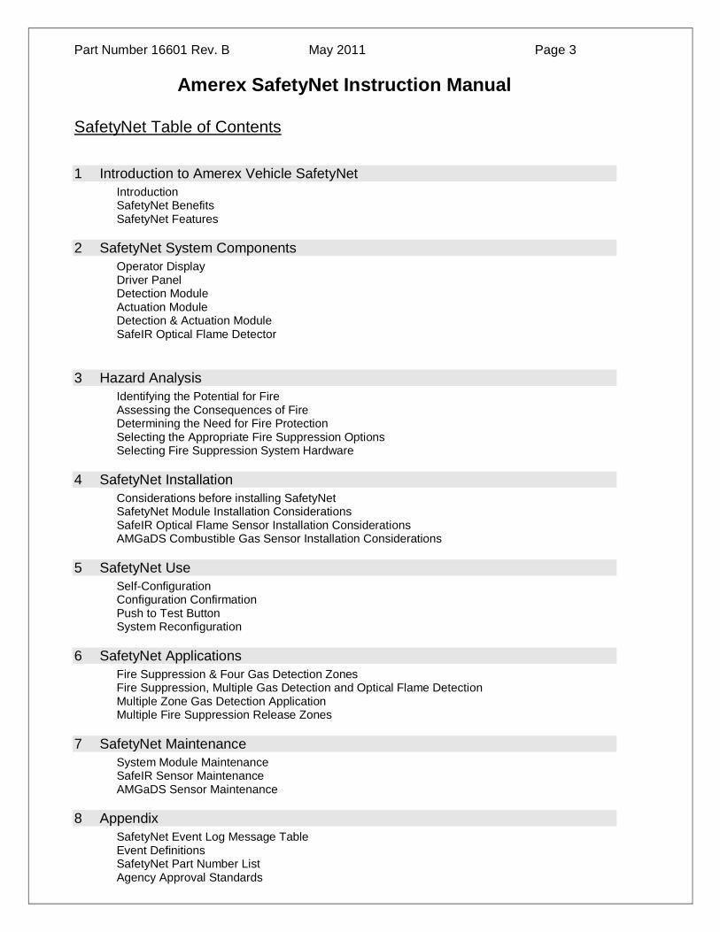
6.1 SafetyNet Applications The following are examples of SafetyNet applications. These are not the only configurations that can be designed. These are only representations of typical applications.
Application Example: Fire Detection/Suppression & Multiple Zone Gas Detection
Application Example: Multiple Gas Detection Zones and Optical Flame Detection

Part Number 16601 Rev. B May 2011 Page 37
Part Number 16601 Rev. B May 2011 Page 38
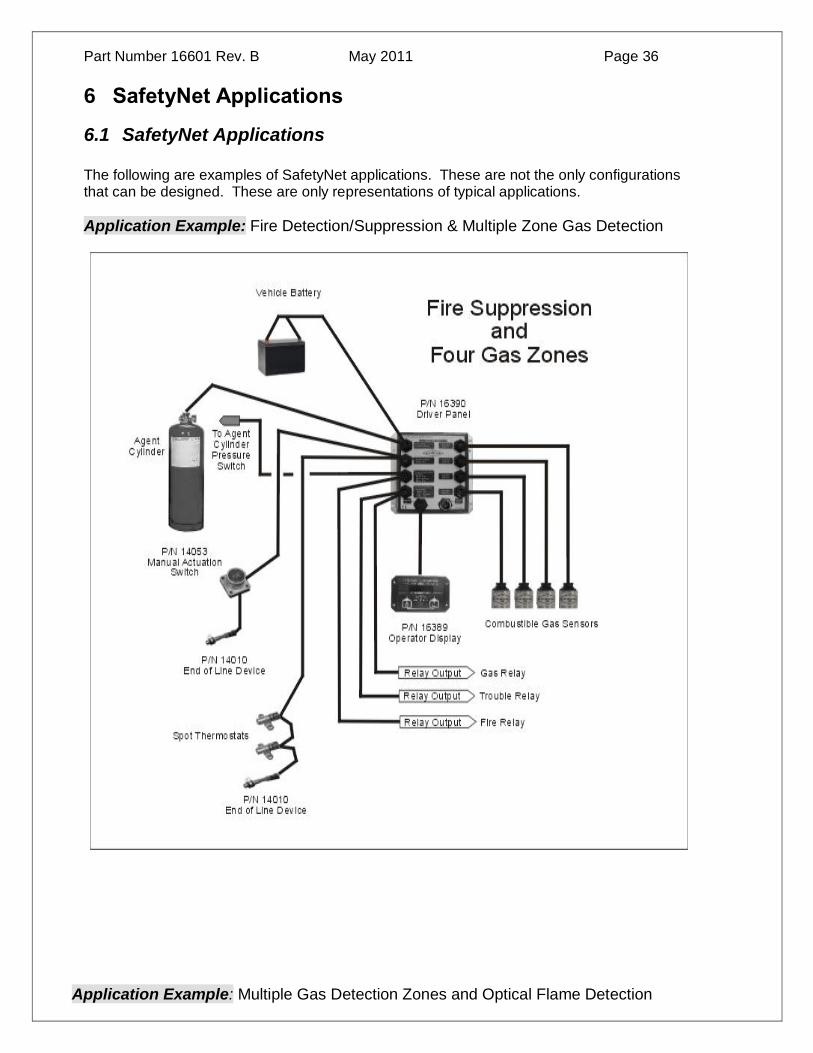
Application Example: Gas Detection, Multiple Detection Zones and Multiple Agent Cylinder Release Zones

Part Number 16601 Rev. B May 2011 Page 39
Application Example: Multiple Zone Gas Detection System

Part Number 16601 Rev. B May 2011 Page 40
Application Example: Gas Detection and Multiple Agent Cylinder Release Zones

SafetyNet System Modules
Ensure all connector ports are covered. While the SafetyNet Module is weather resistant, moisture can enter
uncovered wiring ports and penetrate the module enclosure.
7.1 SafeIR Sensor Maintenance
Safe-IR Optical Flame Detectors do not require any type of field calibration. They are factory tested to respond to the hydrocarbon based flame signature. To be most effective, the sensor lens should be kept clean. Dust, oil, dirt and grease in sufficient quantity can “blind” the sensor and render it inoperable. Wiping the sensors lens clean as necessary with a tissue or soft cloth dampened in wa-ter is recommended. At least semi-annually examine the sensors for damage, dirt, oil and debris. Check that sensor wires are not frayed, pinched, or cut. Test the operation of sensors and Interface Module semi-annually. To test the SafeIR sensors, disconnect all Electric Actuator cables from the Electric Actuator. Replace each Electric Actuator connection with an Alarm Module (P/N 14027). Doing this ensures that it is safe to test the sensors without discharging the fire suppression system extinguishers. With Optical Sensors disabled, expose the sensor lens to the flame from a BIC type cigarette lighter by waving the flame (approximately 1 inch) in front of the sensor lens so as to cre-ate a flickering flame. The sensor should alarm immediately. Warning: Exercise extreme caution when following this procedure. Make absolutely certain no hazards exist that could be ignited by the flame.
7.2 Gas Sensor Maintenance
AMGaDS sensors require very little maintenance. The Gas Sensors are very durable and should
give two years of service, at which time they should be replaced with new sensors. Semi-annually
examine the sensors for contamination or damage. The sensor may be cleaned with a soft brush
under warm running water if needed. Shake off excessive water before reinstalling. Do not blow dry
with compressed air as filter membrane will be damaged. Check that sensor wires are not frayed,
pinched, or cut. Do NOT expose sensors to liquids or chemicals unnecessarily. When cleaning the
vehicle, seal off the sensor(s) with a plastic covering. Harsh chemicals and extremely high tempera-
tures may damage the sensor. Keep sensor(s) sealed until compartment has been completely ven-
tilated. Each sensor has been sealed with a gas permeable, water-resistant pad. This pad is locat-
ed on the inside of the sensor housing. Do not puncture or damage the sensor seal or sensor life
will be significantly shortened.
7.2.1 Test the operation of both sensors and display module semi-annually. Test the gas de-
tection system using the following procedure:
System Visual Inspection.
1. Internal operation of the display panel and relay must be
tested by pressing the Amerex logo button.
2. Ensure that the cable connections at the panel are clean
and have no visible damage with proper strain relief at the
connection.
3. Ensure the cable connected to the gas sensor is supported
and is not free hanging and subject to excessive vibration.
7 SafetyNet Maintenance

System Visual Inspection.—Continued
4. Gas sensor life is two years under normal operat-ing conditions. Replace gas sensors after two years in service.
5. Verify the permeable membrane located at the end of the gas sensor is intact and not covered with oil, grease, or other debris.
System Test for Trace Gas Level (25% LEL).
1. Verify the detection system is in operation and not in alarm.
2. Remove sensor from “P” clamp leaving sensor attached to cable.
3. Connect 25% LEL gas (P/N 20165) to regulator (P/N 20179). Connect hose (P/N 20181)
between regulator and gas calibration adaptor assembly (P/N 20186).
4. Place gas calibration adaptor assembly (P/N 20186) over the gas sensor.
5. Open valve to apply “Trace Gas” (25% LEL) test gas to the gas sensor.
6. The “Trace Gas” LED should begin to flash on the display panel.
7. After one minute the sensor test is complete.
8. If the fault LED is illuminated on the display panel, replace the gas sensor and restart
the test process.
9. Turn off test gas, remove the gas calibration adapter (20179) and reinstall gas sensor.
10. Repeat for each zone.
11. Reorder test gas (P/N 20165) (25%LEL) as required.
System Test for Significant Gas Level (55% LEL)
1. Verify the detection system is in operation and not in alarm.
2. Remove sensor from “P” clamp leaving sensor attached to cable.
3. Connect 55% LEL gas (P/N 20166) to regulator (P/N 20179). Connect hose (P/N 20181)
between regulator and gas calibration adaptor assembly (P/N 20186).
4. Place gas calibration adaptor assembly (P/N 20186) over gas sensor.
5. Open valve to apply “Significant Gas” (55% LEL) test gas to the gas sensor.
6. The “Trace Gas” LED should illuminate on the display panel. After 5 to 7 additional
seconds, the “Significant Gas” LED should illuminate. The audible alarm should sound
and the relay should engage after an approximately 15 second delay.
7. After one minute the sensor test is complete.
8. If the fault LED is illuminated on the display panel, replace the gas sensor and restart
the test process for both trace and significant gas conditions.
9. Turn off test gas, remove the gas calibration adapter (20179) and reinstall gas sensor.
10. Repeat for each zone.
11. Reorder test gas (P/N 20166) as required.

7.3 Automatic Maintenance Test (AMT) Monitor Functions
The latest upgraded SafetyNet Panels include a function of the Push to Test Button that when pressed and held for approximately 15 seconds goes into a maintenance program sequence as per
the following:
1. VFD displays: “Running System Maintenance”
2. VFD displays: “Fire LED Test” Red FIRE LED blinks five times
3. VFD displays: “Power LED Test” Green POWER LED blinks five times
4. VFD displays: “Trouble LED Test” Yellow Trouble LED blinks five times
5. VFD displays: “Trace LED Test” Yellow Trace LED blinks five times
6. VFD displays: “Significant LED Test” Red Significant LED blinks five times
7. VFD displays: “Relay Test” Relay transfers and red relay LED illuminates
8. VFD displays: “Press RELAY RESET button!” When operator presses button, relay resets
and LED goes out.
9. VFD displays: “Relay Test Complete”
10. VFD displays: “Checking Agent Cylinders” SNet checks agent cylinder pressure switch circuit.
11. VFD displays: “Agent Cylinders OK” or “Low Cylinder Pressure. Service System”
12. VFD displays: ”Checking Power Input” VFD displays: “Power @ XX Volts DC”
13. VFD displays: “Checking Back-Up Battery” VFD displays: “Back-Up Battery OK (or Low)”
14. VFD displays: “Checking Gas Sensors” VFD displays: “4 Gas Sensors Found” or “Gas Sen-
sor Fault Found. Service System.”
15. VFD displays: “Checking Class B Circuits” SNet checks continuity and resistance
16. VFD displays: “Class B Circuits OK” or “Class B Circuit Fault Found. Service System”
17. VFD displays: ”Checking Programmable Detectors” SNet checks temperature readings of
PHD’s
18. VFD displays: “4 PHD’s OK” or “PHD Fault Found. Service System”
19. VFD displays: “Checking Actuation Circuit” SNet check circuit continuity and supervision cur-
rent.
20. VFD displays: “Actuation Circuit OK” or “Actuation Circuit Fault Found. Service System”
21. VFD displays: “Checking Audible Alarm” Audible Alarm Sounds.
22. VFD displays: “Press ALARM SILENCE Button” Alarm silences when button is pressed
23. VFD displays: “System Test Completed. System OK” and panel returns to “System OK” or
“System Faults Found. Service System” and Trouble LED illuminates.
Trouble codes are recorded in the event log, and the Trouble LED remains illuminated until faults are corrected. All data test data is retained in the SafetyNet event log and can be printed, transferred to a
maintenance file, thumb drive or other media for retention as needed.
The only other tests that need to be done according to NFPA requirements is blow out the discharge
lines and replace the nozzle caps.
This programming feature can double as a troubleshooting guide as well.

7.4 Spot Heat Detector Maintenance
Service and test the detection network.
Warning: Do not perform these tests on the system if the electric actuator and
control head are installed and connected. System discharge will result.
A. Service the detection network:
Check spot heat sensors for dents, punctures, or other damage.
Spot heat sensors must not be painted. Replace if damaged or painted.
Check all exposed wiring for cuts, abrasion, or heat damage.
Check that all other wiring connections are tight and sealed.
Correct any deficiencies discovered.
B. Test Spot Thermostats
Unplug the electric actuator and attach it to the Alarm Test Module, Amerex P/N 21447. Check that the reset button on the alarm module is depressed. When the alarm test mod-ule is connected, the display panel should indicate a normal condition. Only the green
"System OK" LED should be illuminated. Test the function of each spot heat sensor.
Perform a visual inspection of the heat detector.
During the visual inspection, verify that the sensing shell is free from dents, dings, cracks, scorch marks from flames, or any other physical damage. If the shell has experienced any
of these symptoms, replace immediately.
If the shell has been painted, the unit should be replaced immediately. If a build-up of grease, dust, or any other foreign matter has accumulated on the unit, it may be cleaned
with a vacuum or soft dry cloth. Care should be used to not damage the unit in any way.
Perform an operational verification of the heat detector.
The system must be disabled with use of the 21447 test module/simulator prior to doing
any operational verification tests of the heat detector.
Set-point temperature for each heat detector are:
280°F closes at 280°F +/- 14°F
350°F closes at 350°F +/- 17°F
450°F closes at 450°F +/- 22°F
Hold an electric heat gun near the spot thermostat until the contacts close.
Do not use any other heat source to test spot heat sensors.
Remove heat immediately following activation of the unit.
Do not overheat the set-point of the unit by more than 100°F (55°C) (example: 280°F unit must not be heated beyond 380°F). Overheating the unit beyond recommended limitations
can cause the unit to change set-point temperature rating.

7.5 Linear Heat Detection Cable Maintenance
Test Spot Thermostats
Unplug the electric actuator and attach it to the Alarm Test Module, Amerex P/N 21447.
Check that the reset button on the alarm module is depressed. When the alarm test module is
connected, the display panel should indicate a normal condition. Only the green "System OK"
LED should be illuminated.
Linear heat detection cable assemblies must not be painted. Replace if damaged or painted.
Check all exposed wiring for cuts, abrasion, or heat damage.
Check that all other wiring connections are tight and sealed.
Correct any deficiencies discovered.
Perform a visual inspection of the heat detector.
During the visual inspection, verify that the cable is free from abrasion, cracks, scorch marks from flames, or any other physical damage. If the cable has experienced any of these symp-
toms, replace immediately.
If the cable has been painted, the unit should be replaced immediately. If a build-up of grease, dust, or any other foreign matter has accumulated on the unit, it may be power
washed to remove buildup. Care should be used to not damage the unit in any way.
Perform an operational verification of the heat detector.
The system must be disabled with use of the 21447 test module/simulator prior to doing any
operational verification tests of the heat detection cable.
Verify the Operator Display Panel shows condition Fire Suppression OK with the green LED
illuminated.
Remove the End of Line Module P/N 14010 from the end of the Linear Heat Detection Cir-
cuit.
Plug a Manual Actuation Switch P/N 14053 into the end of the Linear Heat Detection Cir-
cuit.
Plug the End of Line Module into the free end lead of the P/N 14053 Manual Actuation Switch
and verify the green OK LED is illuminated on the Operator Display.
Press and hold the FIRE button on the Manual Actuation Switch and verify the Operator Dis-
play show FIRE condition as indicated by the red FIRE LED and audible alarm.
Part Number 16601 Rev. B May 2011 Page 42
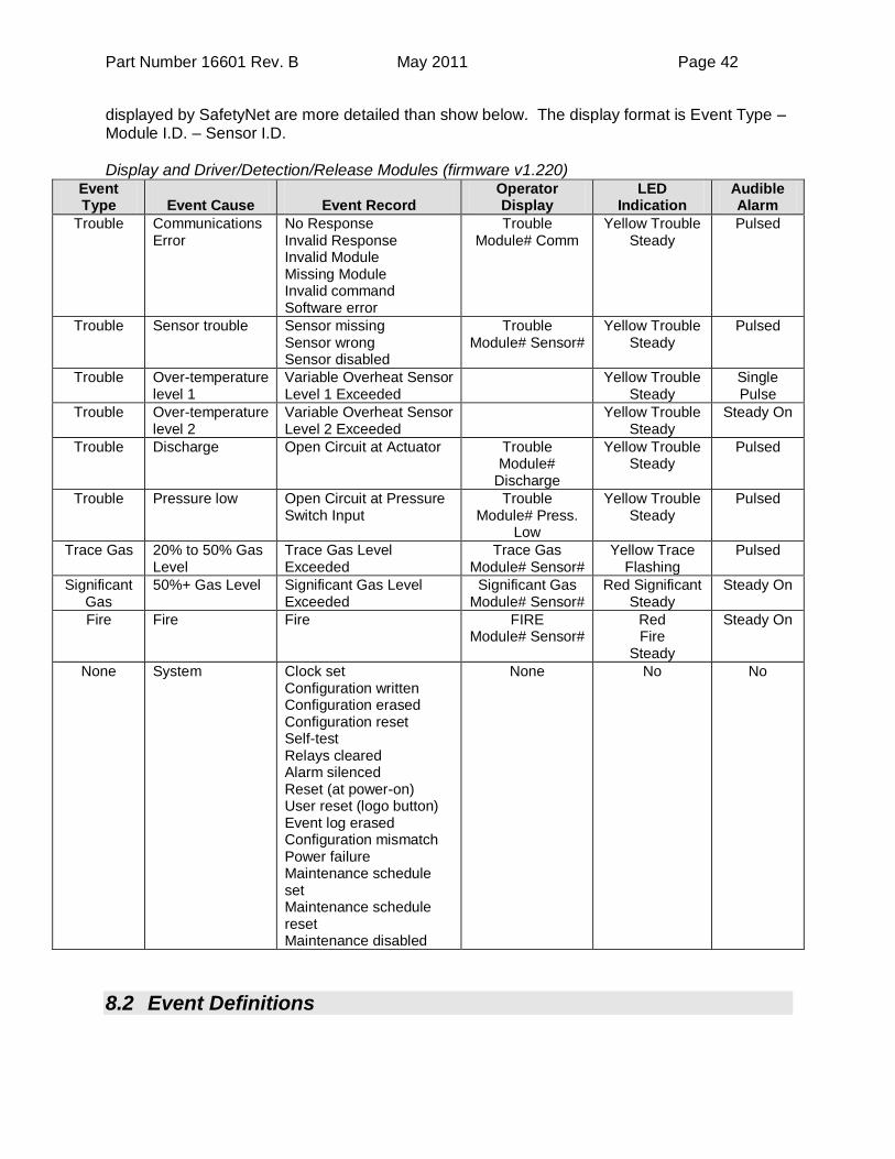
displayed by SafetyNet are more detailed than show below. The display format is Event Type – Module I.D. – Sensor I.D. Display and Driver/Detection/Release Modules (firmware v1.220)
Event Type
Event Cause
Event Record
Operator Display
LED Indication
Audible Alarm
Trouble Communications Error
No Response Invalid Response Invalid Module Missing Module Invalid command Software error
Trouble Module# Comm
Yellow Trouble Steady
Pulsed
Trouble Sensor trouble Sensor missing Sensor wrong Sensor disabled
Trouble Module# Sensor#
Yellow Trouble Steady
Pulsed
Trouble Over-temperature level 1
Variable Overheat Sensor Level 1 Exceeded
Yellow Trouble Steady
Single Pulse
Trouble Over-temperature level 2
Variable Overheat Sensor Level 2 Exceeded
Yellow Trouble Steady
Steady On
Trouble Discharge Open Circuit at Actuator Trouble Module#
Discharge
Yellow Trouble Steady
Pulsed
Trouble Pressure low Open Circuit at Pressure Switch Input
Trouble Module# Press.
Low
Yellow Trouble Steady
Pulsed
Trace Gas 20% to 50% Gas Level
Trace Gas Level Exceeded
Trace Gas Module# Sensor#
Yellow Trace Flashing
Pulsed
Significant Gas
50%+ Gas Level Significant Gas Level Exceeded
Significant Gas Module# Sensor#
Red Significant Steady
Steady On
Fire Fire Fire FIRE Module# Sensor#
Red Fire
Steady
Steady On
None System Clock set Configuration written Configuration erased Configuration reset Self-test Relays cleared Alarm silenced Reset (at power-on) User reset (logo button) Event log erased Configuration mismatch Power failure Maintenance schedule set Maintenance schedule reset Maintenance disabled
None No No
8.2 Event Definitions

Part Number 16601 Rev. B May 2011 Page 43
Module Communications Error – These errors consist of network errors. An error in data transmission or interruption in the data network will cause a Comm Error. Troubleshooting consists of: Check all data cables and verify proper system configuration. Sensor Trouble – This could indicate one of several problems:
1) A system sensor in the SafetyNet configuration is missing, 2) A system sensor is different than the SafetyNet configuration, 3) A system sensor is damaged or disabled, 4) Sensor wiring is broken or disconnected.
Over-temperature level 1 – Variable Overheat Sensor warning level 1 is exceeded. The
sensor temperature level is set at the module level. If this level is exceeded, the event will be recorded and will be indicated by a yellow Trouble LED and pulsed audible alarm.
Over-temperature level 2 – Variable Overheat Sensor warning level 2 is exceeded. The
sensor temperature level is set at the module level. If this level is exceeded, the event will be recorded.
Squib Fault - This could indicate a disconnected actuator cable, open wire in the actuator cable, open or activated actuator. Pressure Low – Open circuit at the agent cylinder pressure switch. This could indicate a
disconnected pressure switch cable, open wire in the pressure switch circuit, or low pressure in the agent cylinder Trace gas – Trace Gas Level is exceeded. Combustible gas exists in the area of the sensor.
The default setting is 20% of the LEL of Methane in a normal atmosphere. Significant gas – Significant Gas Level is exceeded. Combustible gas exists in the area of the sensor. The default setting is 50% of the LEL of Methane in a normal atmosphere. Fire – A sensor has recorded a Fire event. System – A number of conditions can be recorded as System Events. Any user interaction with the Operator Display or Configuration adjustments is recorded as a System Event.
8.3 Agency Approval Standards

Part Number 16601 Rev. B May 2011 Page 44
Factory Mutual Corporation Standard 3260 Radiant Energy-Sensing Fire Detectors for Automatic Fire Alarm Signaling Society of Automotive Engineers SAE J1211 Recommended Environmental Practices for Electronic Equipment Design SAE J1113 Electromagnetic Susceptibility Measurement Procedures for vehicle Components SAE J1455 Joint SAE/TMC Recommended Environmental Practices for electronic equipment (Heavy Duty Trucks) CE Type approval e11*72/245*95/54*1680*00 Radio Interference Suppression (72/245/EEC) as last amended by 95/54/EC
8.4 System Specifications
16389 – SafetyNet Operator Display Operating Voltage 10.5 to 30 vdc
Current Requirement 20mA normal/80mA Alarm - Operator Display Panel only
Event Recording 4000+
Shock (operational) Up to 30 g’s at any axis
Vibration 1 to 1000 Hz; 2.54cm to 0.01 cm double amplitude
Dimensions 5.10”L x 3.25”W x 1.50”H
Weight 8.5 oz. (240g.)
Temperature Operating Range -40 F to 158F (-40C to +70C)
16390 – SafetyNet Driver Panel Operating Voltage 10.5 to 30 vdc
Current Requirement 12 VDC Supply Driver Panel Only: 40mA -Normal Mode; 80mA – in Alarm Mode. 24 VDC Supply Driver Panel Only: 20mA -Normal Mode; 40mA – in Alarm Mode
Agent Cylinder Pressure Monitoring NC or Analog 4-20mA pressure transducer
Relay Contact Ratings 5A@ 30 vdc
Shock (operational) Up to 30 g’s at any axis
Vibration 1 to 1000 Hz; 2.54cm to 0.01 cm double amplitude
Dimensions 5.90”L x 5.90”W x 1.86”H
Weight 24 oz. (750g.)
Temperature Operating Range -40 F to 158F (-40C to +70C)
16391 – SafetyNet Detection Module Operating Voltage 10.5 to 30 vdc
Current Requirement 10mA normal. 20mA in Alarm Mode - Detection Module only
Relay Contact Ratings 5A@ 30 vdc
Shock (operational) Up to 30 g’s at any axis
Vibration 1 to 1000 Hz; 2.54cm to 0.01 cm double
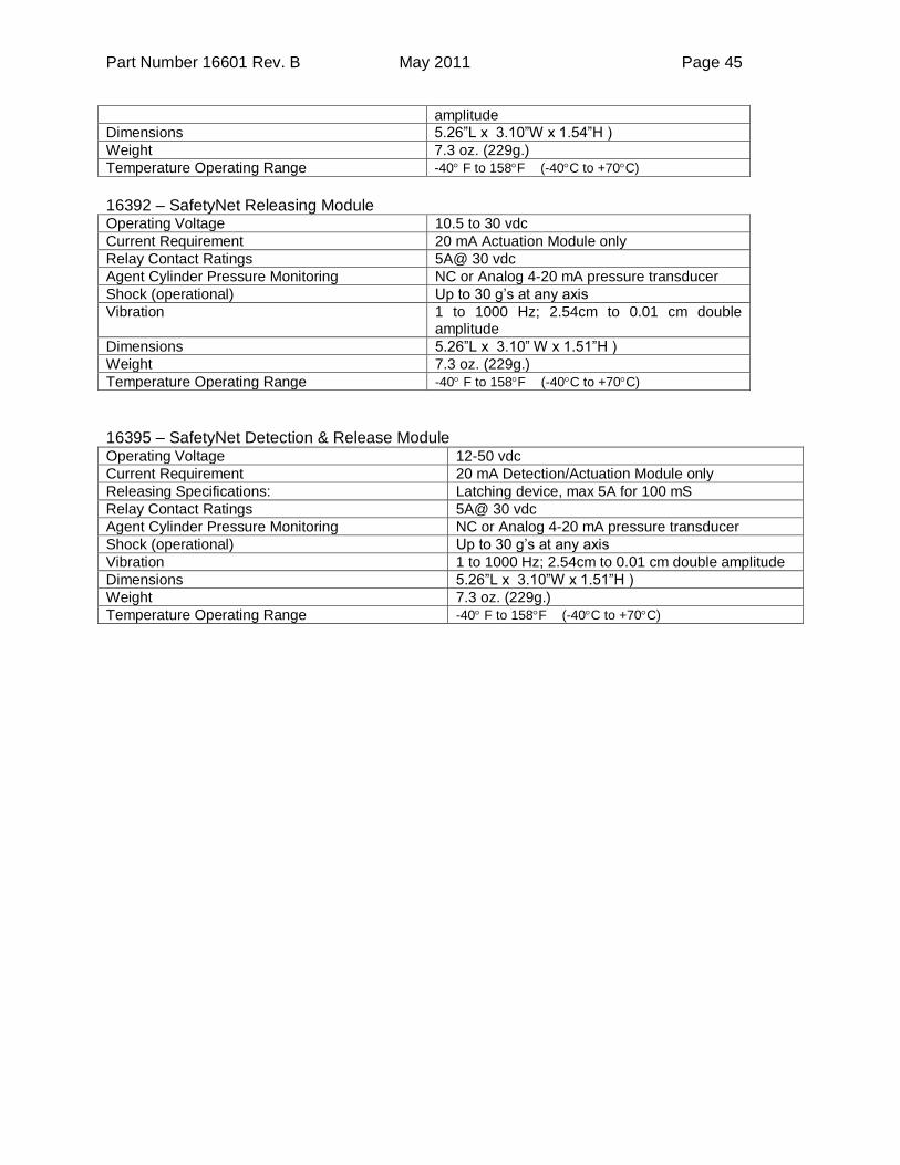
Part Number 16601 Rev. B May 2011 Page 45
amplitude
Dimensions 5.26”L x 3.10”W x 1.54”H )
Weight 7.3 oz. (229g.)
Temperature Operating Range -40 F to 158F (-40C to +70C)
16392 – SafetyNet Releasing Module Operating Voltage 10.5 to 30 vdc
Current Requirement 20 mA Actuation Module only
Relay Contact Ratings 5A@ 30 vdc
Agent Cylinder Pressure Monitoring NC or Analog 4-20 mA pressure transducer
Shock (operational) Up to 30 g’s at any axis
Vibration 1 to 1000 Hz; 2.54cm to 0.01 cm double amplitude
Dimensions 5.26”L x 3.10” W x 1.51”H )
Weight 7.3 oz. (229g.)
Temperature Operating Range -40 F to 158F (-40C to +70C)
16395 – SafetyNet Detection & Release Module Operating Voltage 12-50 vdc
Current Requirement 20 mA Detection/Actuation Module only
Releasing Specifications: Latching device, max 5A for 100 mS
Relay Contact Ratings 5A@ 30 vdc
Agent Cylinder Pressure Monitoring NC or Analog 4-20 mA pressure transducer
Shock (operational) Up to 30 g’s at any axis
Vibration 1 to 1000 Hz; 2.54cm to 0.01 cm double amplitude
Dimensions 5.26”L x 3.10”W x 1.51”H )
Weight 7.3 oz. (229g.)
Temperature Operating Range -40 F to 158F (-40C to +70C)