Embed Size (px)
Citation preview
May 8, 2015 BSEE HPHT Forum
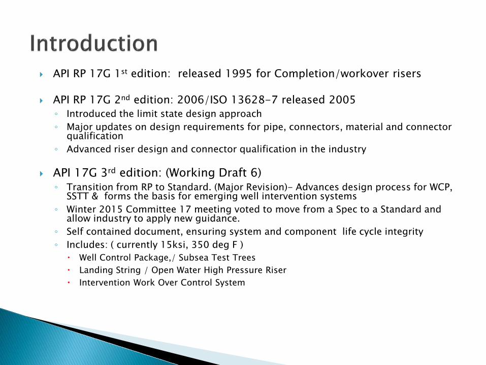
API RP 17G 1st edition: released 1995 for Completion/workover risers
API RP 17G 2nd edition: 2006/ISO 13628-7 released 2005 ◦ Introduced the limit state design approach ◦ Major updates on design requirements for pipe, connectors, material and connector
qualification ◦ Advanced riser design and connector qualification in the industry
API 17G 3rd edition: (Working Draft 6) ◦ Transition from RP to Standard. (Major Revision)- Advances design process for WCP,
SSTT & forms the basis for emerging well intervention systems ◦ Winter 2015 Committee 17 meeting voted to move from a Spec to a Standard and
allow industry to apply new guidance. ◦ Self contained document, ensuring system and component life cycle integrity ◦ Includes: ( currently 15ksi, 350 deg F )
Well Control Package,/ Subsea Test Trees Landing String / Open Water High Pressure Riser Intervention Work Over Control System
Working Draft 6 sent to API April 22 for distribution to committee 17
Requesting comments for the following sections: ◦ Materials, ◦ Connector qualification, ◦ Controls
Editorial team continuing to review the above
sections line by line
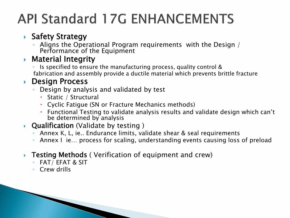
Safety Strategy ◦ Aligns the Operational Program requirements with the Design /
Performance of the Equipment Material Integrity ◦ Is specified to ensure the manufacturing process, quality control & fabrication and assembly provide a ductile material which prevents brittle fracture
Design Process ◦ Design by analysis and validated by test Static / Structural Cyclic Fatigue (SN or Fracture Mechanics methods) Functional Testing to validate analysis results and validate design which can’t
be determined by analysis Qualification (Validate by testing ) ◦ Annex K, L, ie.. Endurance limits, validate shear & seal requirements ◦ Annex I ie… process for scaling, understanding events causing loss of preload
Testing Methods ( Verification of equipment and crew) ◦ FAT/ EFAT & SIT ◦ Crew drills
0
0.1
0.2
0.3
0.4
0.5
0.6
0.7
0.8
0.9
1
1.1
0 0.1 0.2 0.3 0.4 0.5 0.6 0.7 0.8 0.9 1 1.1
Ben
ding
mom
ent
Internal Pressure = XXX
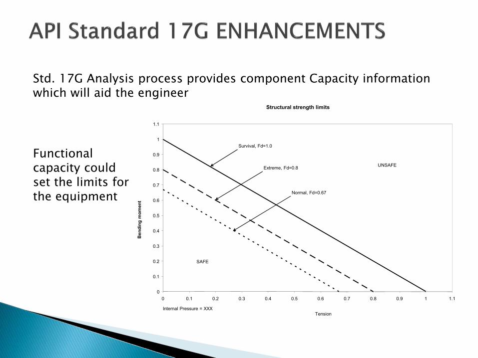
Survival, Fd=1.0
Extreme, Fd=0.8
Normal, Fd=0.67
UNSAFE
SAFE
Tension
r
Structural strength limits
Std. 17G Analysis process provides component Capacity information which will aid the engineer
Functional capacity could set the limits fothe equipment
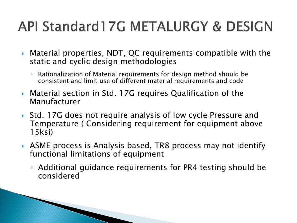
Material properties, NDT, QC requirements compatible with the static and cyclic design methodologies ◦ Rationalization of Material requirements for design method should be
consistent and limit use of different material requirements and code
Material section in Std. 17G requires Qualification of the Manufacturer
Std. 17G does not require analysis of low cycle Pressure and Temperature ( Considering requirement for equipment above 15ksi)
ASME process is Analysis based, TR8 process may not identify functional limitations of equipment ◦ Additional guidance requirements for PR4 testing should be
considered
Various connectors within Equipment range Need industry review and comments to refine Qualification testing is required to ensure that functional
limits are understood Rationalize large bore high capacity hydraulic connector
testing
Varied system requirements ◦ Safety system requirements vary ◦ Deeper and higher pressure require ◦ Bench testing of controls to validate analysis ◦ Request industry review
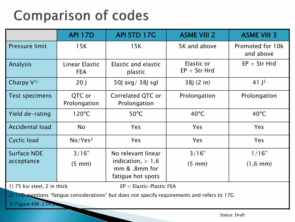
API 17D API STD 17G ASME VIII 2 ASME VIII 3 Pressure limit 15K 15K 5K and above Promoted for 10k
and above
Analysis Linear Elastic FEA
Elastic and elastic plastic
Elastic or EP + Str Hrd
EP + Str Hrd
Charpy V1) 20 J 50J avg/ 38J sgl 38J (2 in) 41 J3
Test specimens QTC or Prolongation
Correlated QTC or Prolongation
Prolongation Prolongation
Yield de-rating 120ºC 50ºC 40ºC 40ºC
Accidental load No Yes Yes Yes
Cyclic load No/Yes2 Yes Yes Yes
Surface NDE acceptance
3/16” (5 mm)
No relevant linear indication, > 1,6 mm & .8mm for fatigue hot spots
3/16” (5 mm)
1/16” (1,6 mm)
1) 75 ksi steel, 2 in thick EP = Elastic-Plastic FEA 2) 17D mentions “fatigue considerations” but does not specify requirements and refers to 17G 3) Figure KM-234.2a
Status: Draft
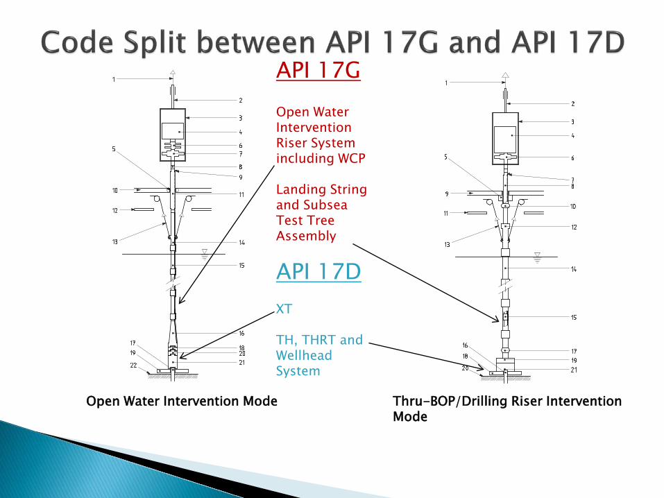
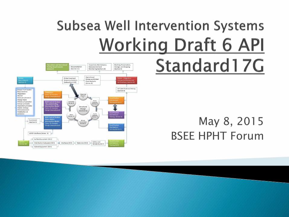
Open Water Intervention Mode
I
i
Thru-BOP/Drilling Riser Intervention Mode
Open Water ntervention Riser System ncluding WCP
Landing String and Subsea Test Tree Assembly
API 17D XT
TH, THRT and Wellhead System
API 17G
Design method consistent to dovetail with TR8: ◦ The static design method gives consistent safety margin against
failure ◦ Provides consistent results for complex geometries and loads ◦ The use of elastic-plastic method provides knowledge of strain in
components Fatigue failure criteria dovetails with TR8 (below WCP, SSTT
where primary barrier resides) so: ◦ S-N curves applicable for environmental cyclic loads (>10,000
cycles per day) ◦ Use of calibrated fatigue design factors for offshore applications
(i.e. high fatigue design factor to limit potential crack size) ◦ Inspectable components (i.e. temporary equipment)
QUESTIONS?
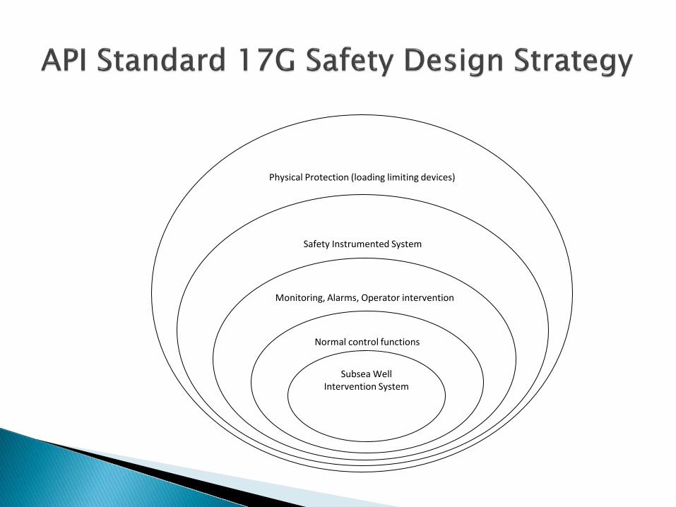
Physical Protection (loading limiting devices)
Safety Instrumented System
Monitoring, Alarms, Operator intervention
Normal control functions
Subsea Well Intervention System