Embed Size (px)
Citation preview
April 26, 2005
Headphone Amplifier & Equalizer
May05-01
Project Team Information• Team Members
– Jennifer Bruner, Electrical Engineering– Mike Dierickx, Electrical Engineering– Rachel Hager, Electrical Engineering– Kurtis Kenne, Electrical Engineering
• Advisors– John Lamont– Ralph Patterson III
• Client – Senior Design
Presentation Outline• List of Definitions• Problem Statement & Proposed
Approach• Operating Environment• Intended User(s) & Use(s)• Assumptions & Limitations• End Product• Approaches Considered and Used
Presentation Outline Cont.• Accomplishments• Schedules & Hours Worked• Resource Requirements & Project
Costs• Project Evaluation • Lessons Learned• Risk & Risk Management• Closing Summary
Acknowledgements
• HeadWize, specifically Chu Moy, for the audio schematics
• Jason Boyd, the brain behind the PCB layout and soldering
List of Definitions• Amplifier – The circuitry that allows one to
adjust the overall power and thus volume.• Cross-fed Delay Filter - A filter which
simulates a surround sound experience by combining both channels with time delay and attenuation in each ear.
• Equalizer – The circuitry that allows one to tune the relative power of individual frequency bands of an audio signal.
Problem Statement• Design a portable audio device capable of
driving a set of high-fidelity headphones with a soundstage offering the user the ability to adjust a 3-band equalizer.
Proposed Approach• Research and test audio schematics provided
by HeadWize and develop a design fitting the functional requirements set forth by the project advisors.
Operating Environment
• Encompasses all portable uses in both indoor and outdoor environments– Portability
• Dimensions no greater than 5” x 5” x 2.5”– Durability
• Extreme temperatures• Possibility of being dropped
Intended User(s) & Use(s)• General public
– Specifically enthusiasts of music• Use in conjunction with a portable audio
source, such as a CD or MP3 player
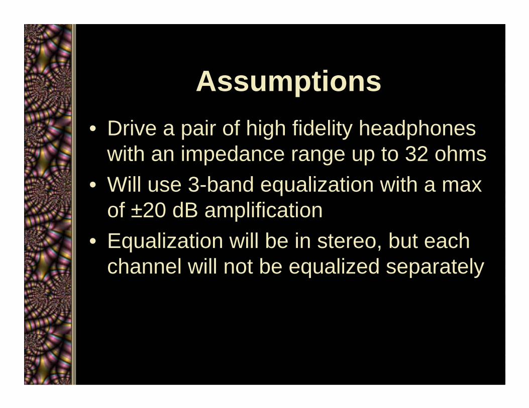
Assumptions• Drive a pair of high fidelity headphones
with an impedance range up to 32 ohms• Will use 3-band equalization with a max
of ±20 dB amplification• Equalization will be in stereo, but each
channel will not be equalized separately

Limitations• The device must have the capability to charge on 12
VDC, and operate on an internal power supply of six – 1.2 V (AA) NiMH rechargeable batteries
• The device will include at minimum a 3.5 mm input jack, a 3.5 mm headphone jack, a volume control, a power switch, 3-band equalizer, and a pilot light
• Since the device will be portable, it must be able to withstand extreme temperatures and be durable enough to withstand being dropped
• The MSRP (Manufacturers Suggested Retail Price) should not exceed $50.
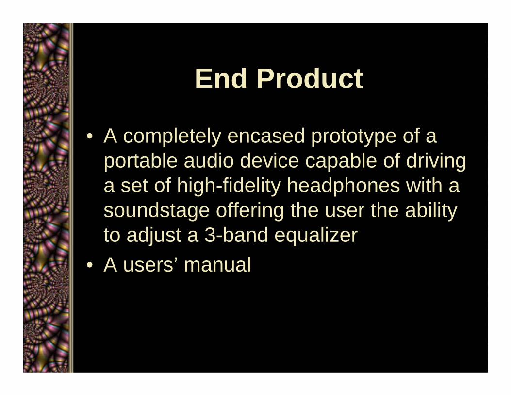
End Product
• A completely encased prototype of a portable audio device capable of driving a set of high-fidelity headphones with a soundstage offering the user the ability to adjust a 3-band equalizer
• A users’ manual

Technical Approaches
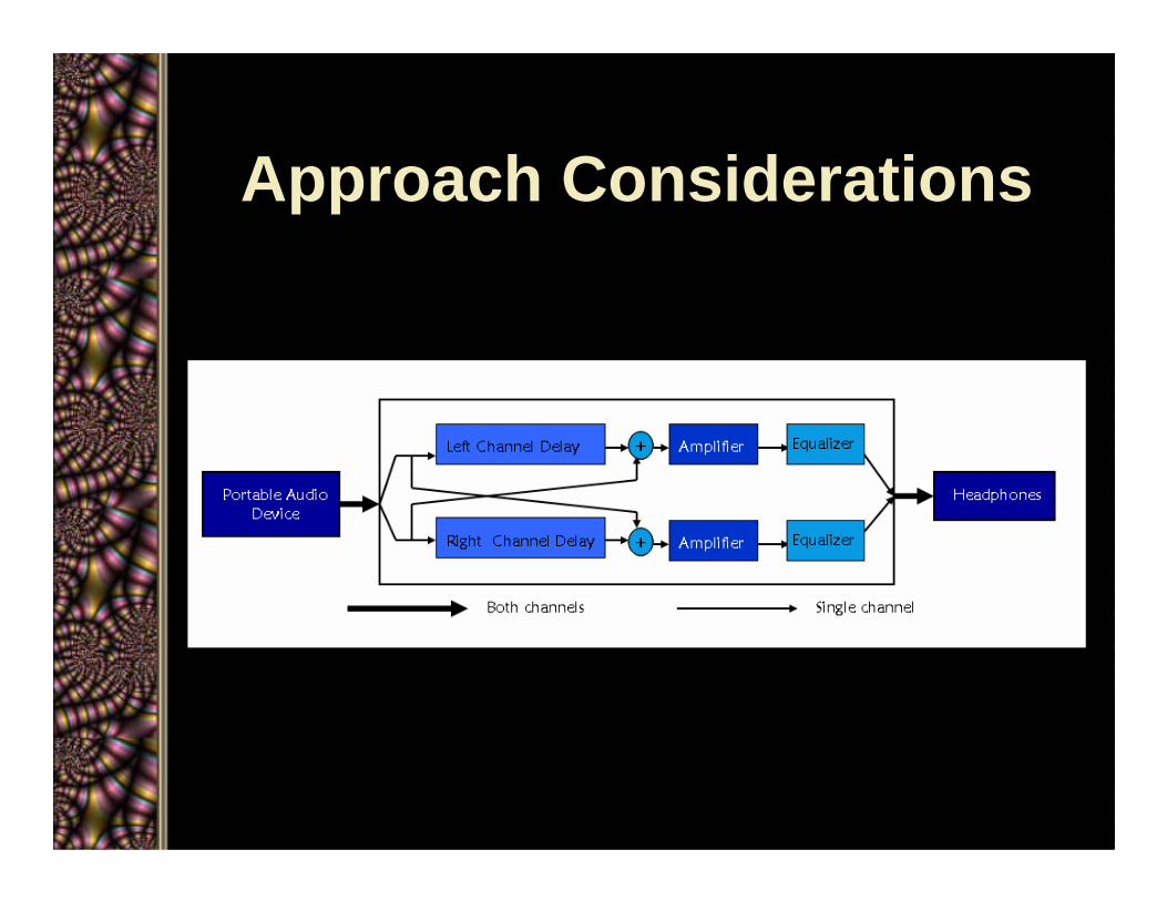
Approach Considerations

Approach Used
• There are four primary components
– Amplifier
– Equalizer
– Soundstage Simulator
– Battery and Casing
Amplifier
• Should be superior to the digital “Class D” part contained in portable players
• Designed to have a voltage gain from zero (off) to about 2.5
• Guarded at the input by an AC couple to eliminate noise

Amplifier
Equalizer
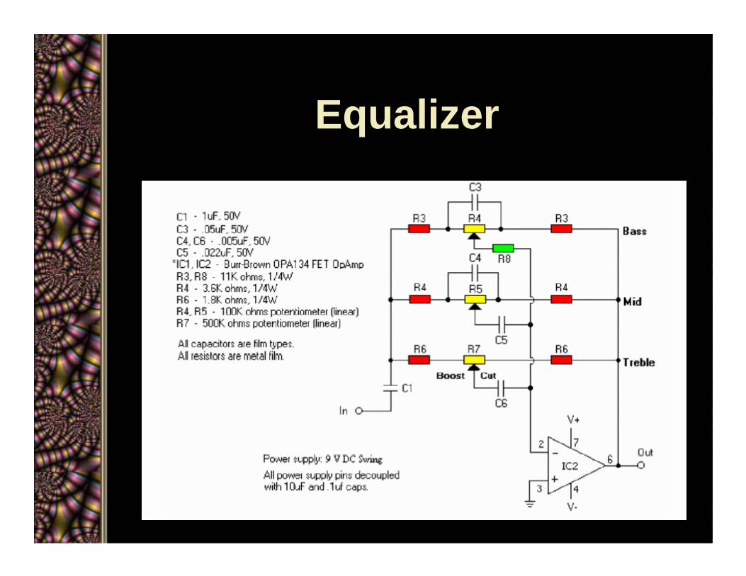
• Both passive and active types• Chose an active “Baxandall” type with
about ±20 dB in each channel with centers at 300, 1050, and 1700 Hz
• This design was highly tunable, it can very nearly silence a band
Equalizer
Cross-fed Delay Filter
• Creates a proper “soundstage” using passive filters
• The soundstage is typically not present in studio recordings, but much more in symphonic or marching band tracks

Cross-fed Delay Filter
Headphone User
Cross-fed Delay Filter
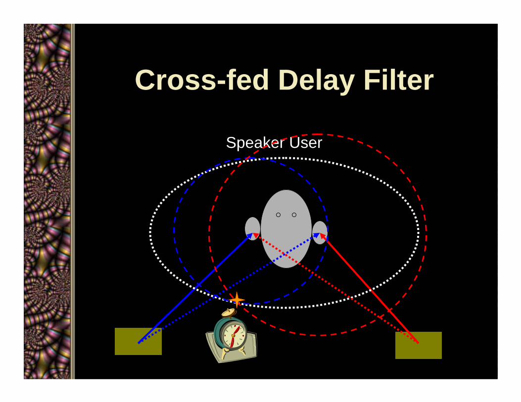
Speaker User
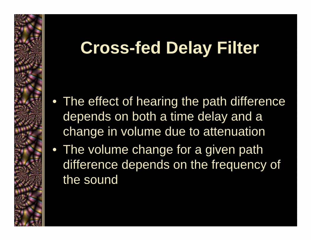
Cross-fed Delay Filter
• The effect of hearing the path difference depends on both a time delay and a change in volume due to attenuation
• The volume change for a given path difference depends on the frequency of the sound
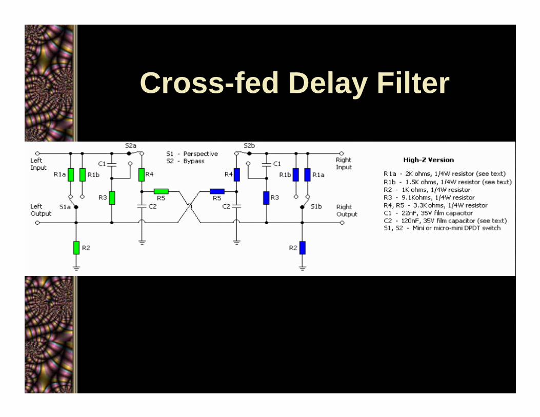
Cross-fed Delay Filter
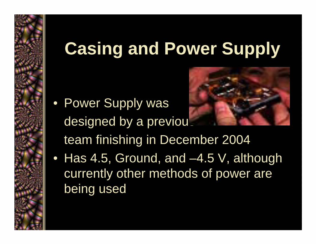
Casing and Power Supply
• Power Supply wasdesigned by a previousteam finishing in December 2004
• Has 4.5, Ground, and –4.5 V, although currently other methods of power are being used

Casing and Power Supply
• Right now, casing has been chosen to accommodate the single 9 V cell
• Case for our first prototype has been chosen

Accomplishments

Accomplishments• Researched different audio schematics
published by various authors at www.headwize.com
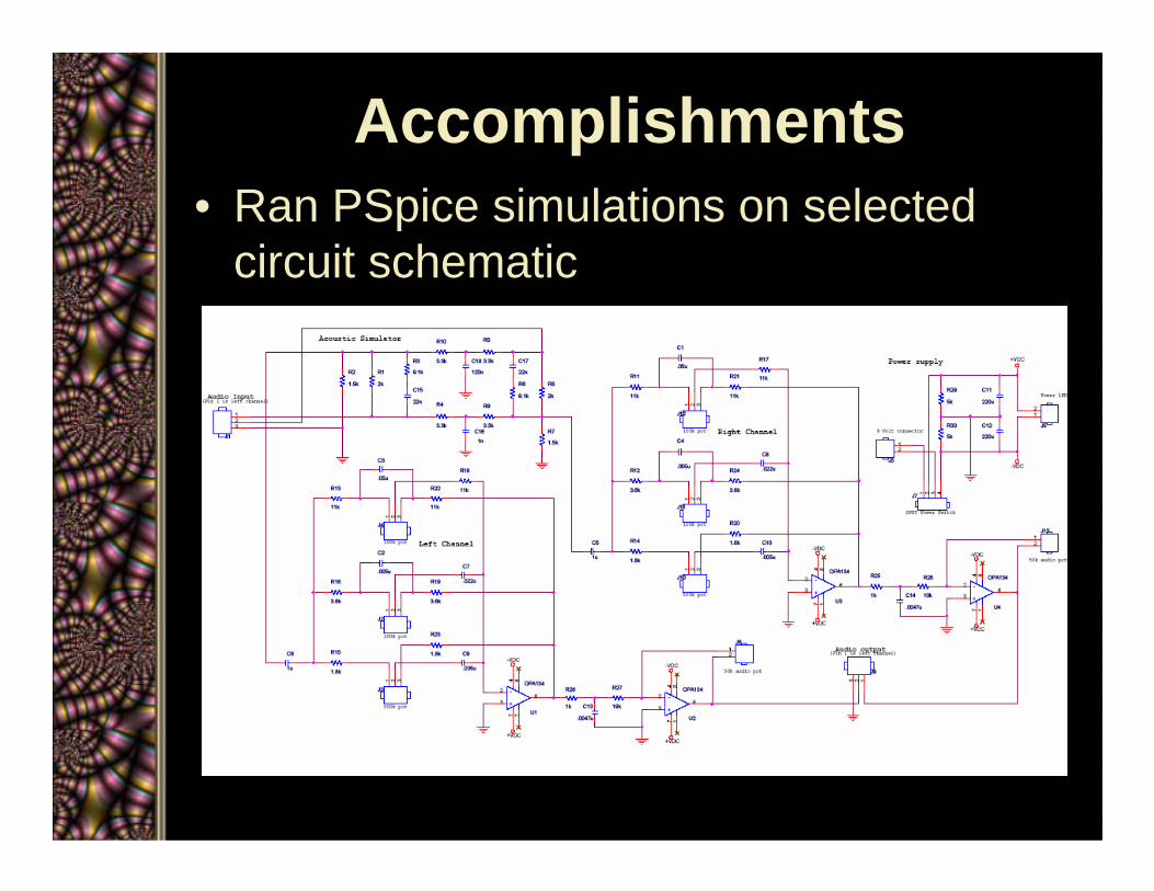
Accomplishments• Ran PSpice simulations on selected
circuit schematic
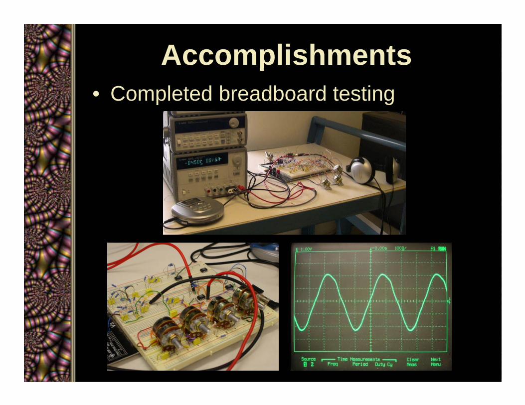
Accomplishments• Completed breadboard testing
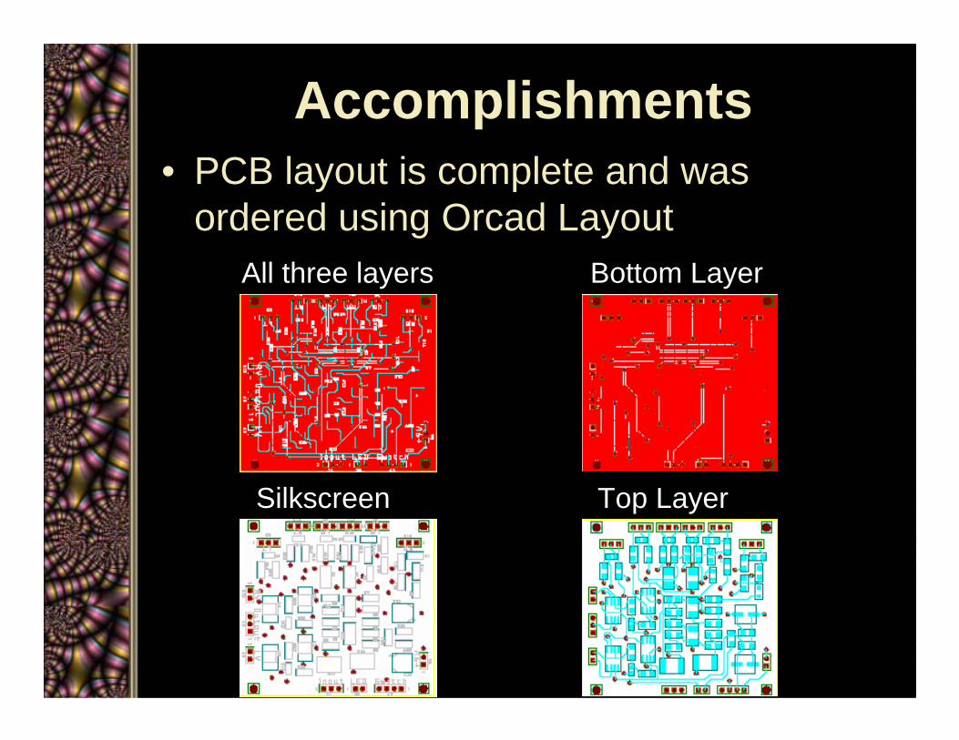
Accomplishments• PCB layout is complete and was
ordered using Orcad LayoutAll three layers Bottom Layer
Silkscreen Top Layer
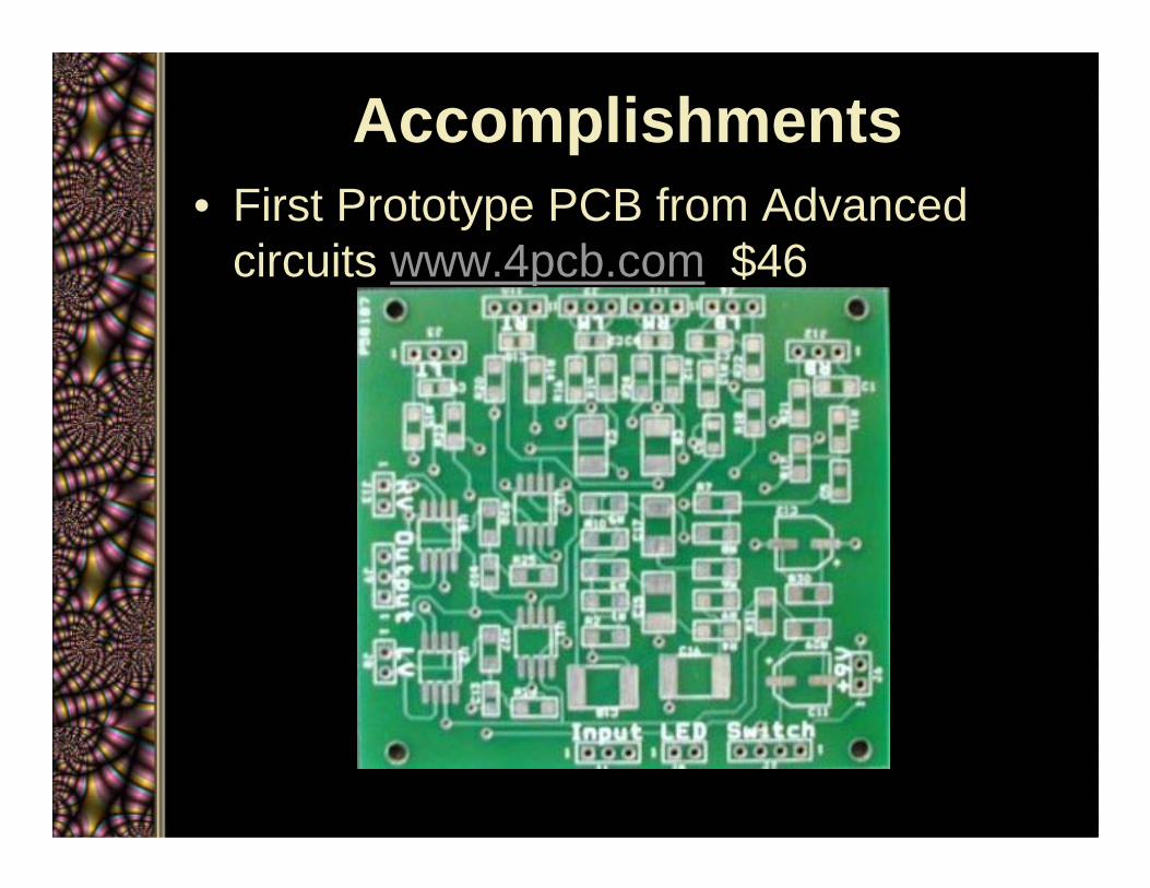
Accomplishments• First Prototype PCB from Advanced
circuits www.4pcb.com $46
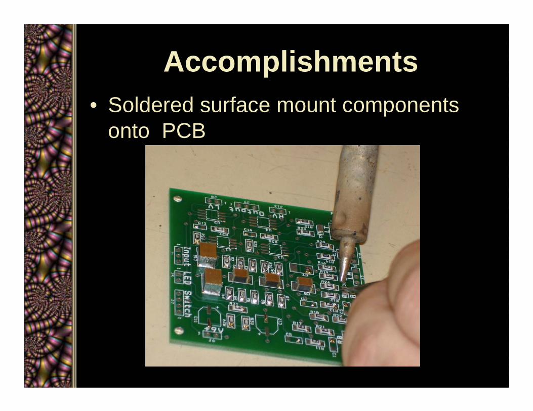
Accomplishments• Soldered surface mount components
onto PCB
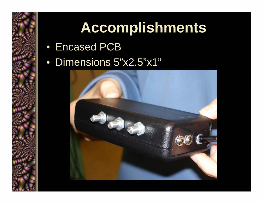
Accomplishments• Encased PCB • Dimensions 5”x2.5”x1”
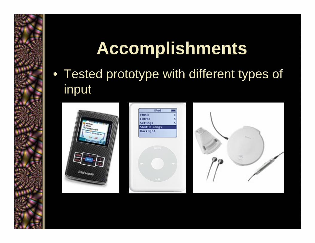
Accomplishments• Tested prototype with different types of
input

Accomplishments• Created users manual

Schedule and Resources
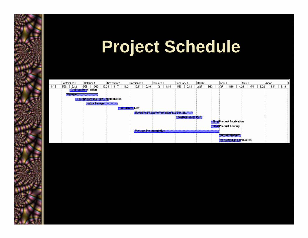
Project Schedule
Schedule• Power supply caused major delays
• Some tasks took longer than expected– Research– Parts and technology considerations– Breadboard implementation & testing
• Team finished on schedule
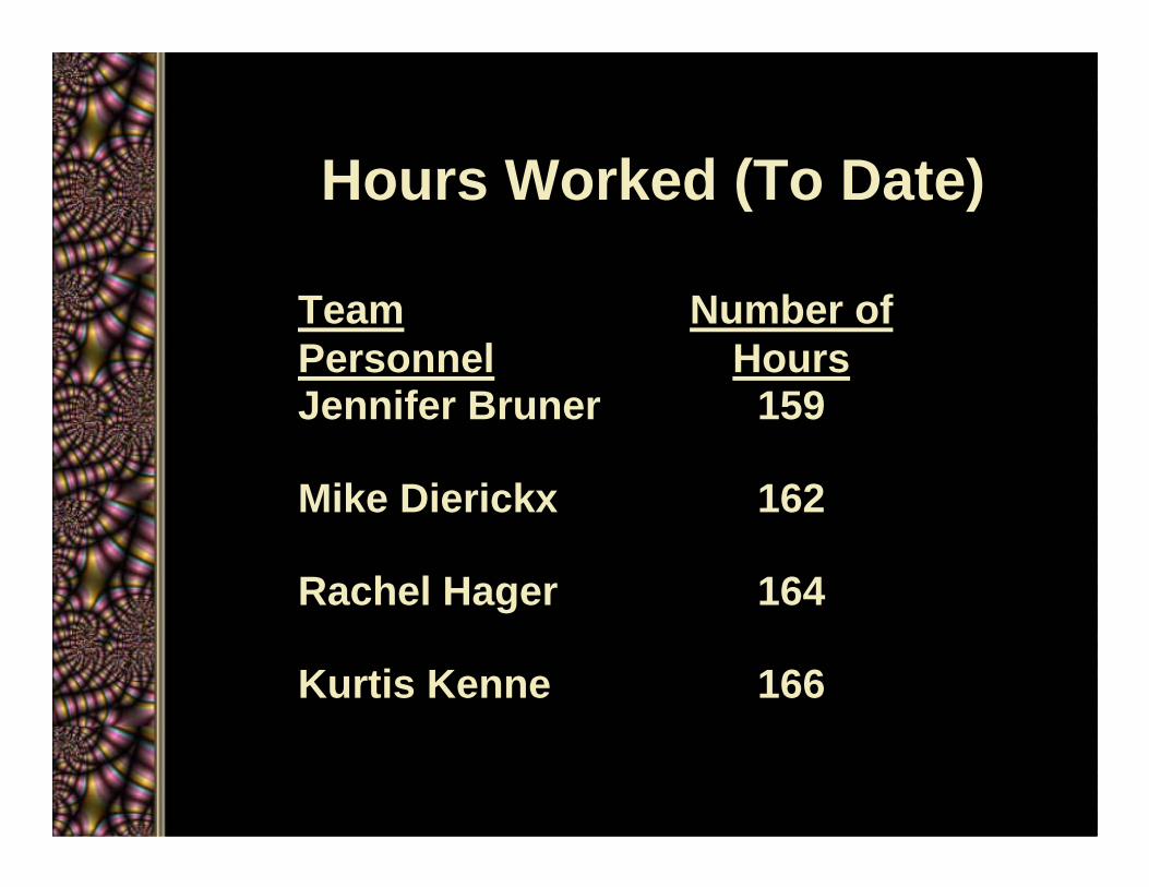
Hours Worked (To Date)
166Kurtis Kenne
164Rachel Hager
162Mike Dierickx
159Jennifer Bruner
Number of Hours
Team Personnel
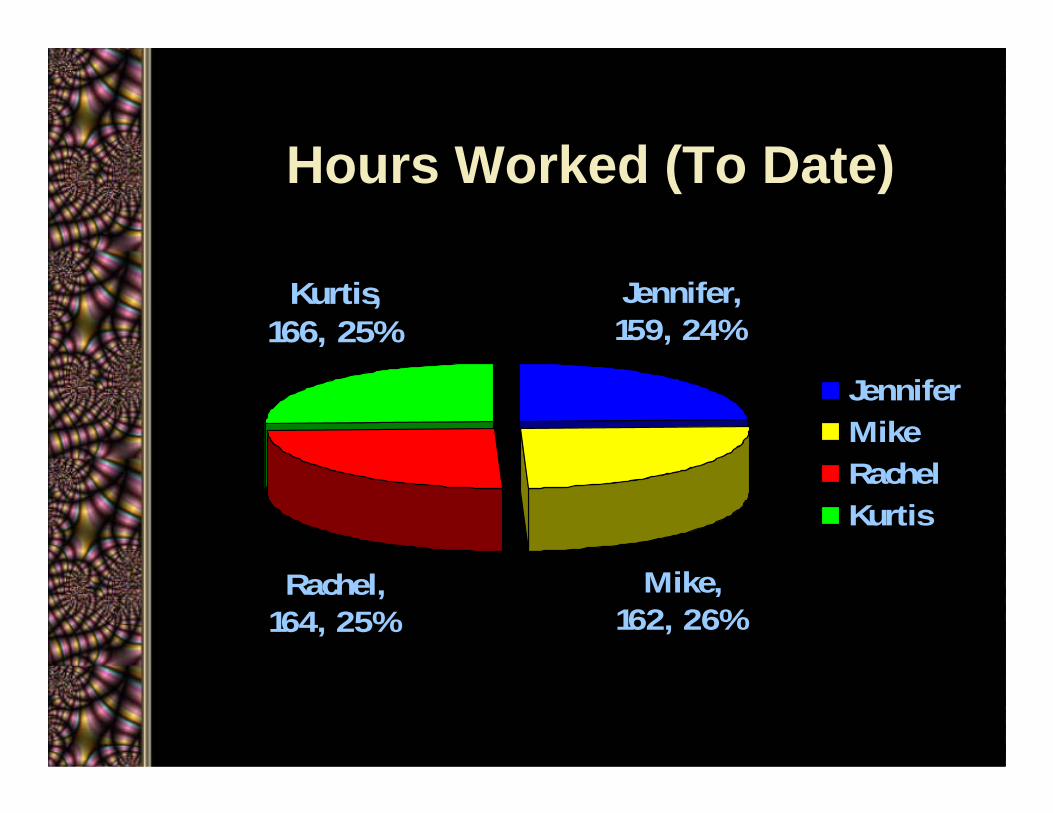
Hours Worked (To Date)
Jennifer, 159, 24%
Rachel, 164, 25%
Kurtis, 166, 25%
Mike, 162, 26%
JenniferMikeRachelKurtis
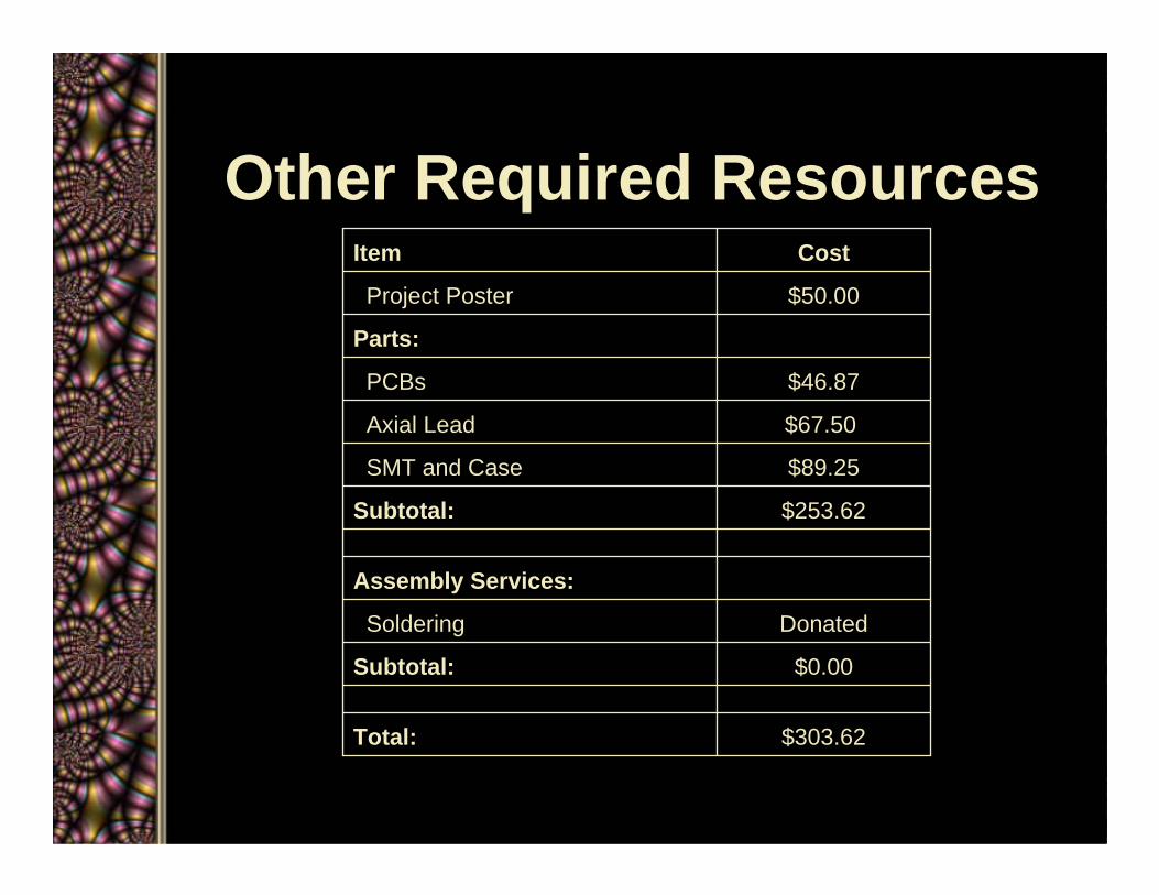
Other Required Resources
$303.62Total:
$0.00Subtotal:
DonatedSoldering
Assembly Services:
$253.62Subtotal:
$89.25SMT and Case
$67.50Axial Lead
$46.87PCBs
Parts:
$50.00Project Poster
CostItem
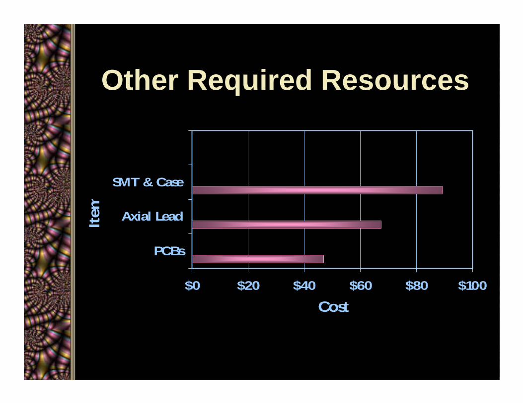
Other Required Resources
$0 $20 $40 $60 $80 $100
PCBs
Axial Lead
SMT & Case
Item
Cost
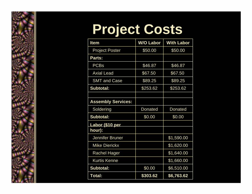
Project Costs
$6,763.62$303.62Total:$6,510.00$0.00Subtotal:$1,660.00Kurtis Kenne
$1,640.00Rachel Hager
$1,620.00Mike Dierickx
$1,590.00Jennifer Bruner
Labor ($10 per hour):
$0.00$0.00Subtotal:DonatedDonatedSoldering
Assembly Services:
$253.62$253.62Subtotal:$89.25$89.25SMT and Case
$67.50$67.50Axial Lead
$46.87$46.87PCBs
Parts:$50.00$50.00Project Poster
With LaborW/O LaborItem
Project Evaluation
• Project Completed Successfully– Met design requirements– Product is durable and portable– Met expected cost– Provides unique listening
experience
Lessons Learned• Gained knowledge of audio
schematics• Importance of breadboard testing –
group knowledge of board layout• Set-back with the power supply• Issues with noise • Start testing earlier
Risk & Risk Management• Anticipated few problems with design layout
– Ran PSpice simulations– Breadboard testing
• Unanticipated problems with the power supply developed by previous senior design team– Sent power supply to get fixed– Fabricated device using a 9V battery supply
• Unanticipated noise during breadboard testing– Fixed some issues due improper grounding – Fabrication of PCB eliminated noise issues
Closing Summary• Problem
– Need a portable audio device capable of driving a set of high-fidelity headphones with a soundstage offering the user the ability to adjust a 3-band equalizer.
• Solution– Designed a device that includes an amplifier,
equalizer, and acoustic simulator, all placed into an economical package
• Result– Functional prototype was developed with
users’ manual

¿Questions?


![Building Regs 1997_TGD-B_Fire Safety_[May05 Reprint]](https://img.pdfslide.net/doc/110x75/577cc4ca1a28aba7119a73dc/building-regs-1997tgd-bfire-safetymay05-reprint.jpg)