Embed Size (px)
Citation preview

The Profile System
English 1/2011

Product RangeProduct RangeProduct RangeProduct RangeProduct Range
extreme strong dependable
The key to success!
Applications• machine bases • assembly and inspection stations • special shelves• machine enclosures • transfer and supply trolleys • plant equipment• machine guarding • partitions and protective walls • display systems• work stations • protective and work cabins • exhibition cabinets and stands
The ideal profile systemMayTec offers a comprehensive, harmonisedprofile system. All profiles can be combinedin any way imaginable.
The accessories provide functional andaesthetic solutions for a wide range ofapplications.
ServiceThe MayTec service is as versatile as theMayTec profile system.You may choose:
• delivery of standard elements ex factory• delivery of profiles and accessories cut to
size according to parts list for customer’sassembly
• delivery of pre-fitted modular• delivery of completely assembled units• assembly at your premises
ImplementationThe MayTec profile system is easy toprocess and quick to assemble. Its flexibleand modular construction means it can beeasily modified and is reusable at any time.
An experienced team will support you inimplementing the MayTec system, tailored toyour individual applications, taking intoconsideration your required dimensions,loading capacity and stability.
The Profile System
The Personnel Transfer System
Curved Profiles
The Telescopic System
The Tube Clamping System
Safety Barriers
The Linear System
The Clean-Room System
The Conveyor System
MayTMayTMayTMayTMayTec System Tec System Tec System Tec System Tec System Technologyechnologyechnologyechnologyechnology Solutions with Innovative ProfileSolutions with Innovative ProfileSolutions with Innovative ProfileSolutions with Innovative ProfileSolutions with Innovative Profile

1
0
3
4
5
6
7
8
9
1
2
RegisterRegisterRegisterRegisterRegister
Table of contents
Introduction 1.0
Profiles Summary
Profiles 1.1
Profile machining 1.1A
- Coding examples 1.1B
Technical data 1.1C
Profile selection range 1.1D
Profile applications 1.1E
- Curved profiles 1.1E
Connection system Summary
Connector selection 1.2
Connectors 1.2A
- Cross bushings 1.2B
- Components 1.2C
- Special cases 1.2D
Connection possibilities 1.2E
Connector-Strength values 1.2F
Connection elements 1.29
Accessories Summary
Fastening elements 1.3
Installation accessories 1.4
Pneumatic accessories 1.5
Additional accessories 1.6
Electrical accessories 1.7
Panel elements 1.8
Washers, screws and tools 1.9
Subject index

2
TTTTTable of contentsable of contentsable of contentsable of contentsable of contents
Introduction ....................................... 51.01 Symbols, Abbreviations, Special characters ................. 51.02 Slot system .................................................................... 61.03 Numerical key for articles .............................................. 7
1.1 Profiles ............................................ 81.04 Summary: Profiles ......................................................... 81.04 Profiles (plain) ................................................... 8, 91.04 Profiles (with grooves) ........................................... 91.04 Special profiles (plain) .......................................... 101.05 Special profiles ..................................................... 111.09 Profile group 16 mm, E3-slot, P .................................. 121.10 Profile group 16 mm, F-slot, P .................................... 121.10 Profile group 20 mm, H-slot, P ................................... 131.11 Profile group 20 mm, F-slot, P .................................... 151.11 Profile group 30 mm, F / E4-slot, P ............................. 161.11 Profile group 40 mm, E3-slot, P .................................. 201.11 Profile group 45 mm, E4-slot, P .................................. 281.11 Profile group 50 mm, E4-slot, P .................................. 311.11 Profile group 60 mm, E4-slot, P .................................. 321.11 Profiles 48, round, P ................................................... 331.11 Profiles hexagonal/octagonal, P .................................. 331.11 Profile group 30 mm, F-slot ........................................ 341.11 Profile group 40 mm, E3-slot ...................................... 361.11 Profile group 45 mm, E4-slot ...................................... 401.11 Profile group 50 mm, E4-slot ...................................... 421.11 Profile group 60 mm, E4-slot ...................................... 441.14 Panel profiles 30, F-slot, P .......................................... 451.14 Panel profiles 40, E3-slot, P ........................................ 461.14 Panel profiles 50, E4-slot, P ........................................ 471.15 Wire net profiles 30, F-slot, P ...................................... 481.15 Wire net profiles 40, F / E3-slot, P .............................. 481.17 Tube profiles 30, P ...................................................... 49
Special profiles ............................................................ 505.11 Roller profiles ..................................................... 509.11 Telescopic profiles, E3-slot, P ............................ 51
1.19 Special profiles ............................................................ 521.19 Profile pre-cut lids ................................................ 521.19 Hollow profiles ...................................................... 521.19 Base profiles ......................................................... 521.19 Angle profiles ........................................................ 531.19 Wire net mounting profiles ................................... 531.19 Grab handle profiles .............................................. 531.19 U-profiles .............................................................. 541.19 C-track .................................................................. 541.19 Sliding profiles ...................................................... 541.19 Panel framing profile ............................................ 541.19 Tubes .................................................................... 551.19 Hinge profiles ................................................. 55, 561.19 T-Slot profiles ....................................................... 561.19 Slide-slot profiles .................................................. 571.19 19" profiles ............................................................ 571.19 E-trunking profiles ................................................ 581.1A Profile machining ........................................................ 601.1A Summary .............................................................. 601.1A Order description .................................................. 601.1A Order example ...................................................... 601.1A Saw cut ................................................................. 611.1A Cross bushing bore .............................................. 621.1A Bores .................................................................... 621.1A Cross bore ............................................................ 621.1A Thread ................................................................... 621.1A Direction and Position .......................................... 63
Article number group Page Article number group Page
1.1B Profile machining: Coding examples ........................... 641.1B for price group 1 ................................................... 641.1B for price group 2 ................................................... 651.1B for price group 3 ................................................... 661.1B Order example for special design ......................... 661.1C Technical data .............................................................. 671.1D Profile selection range ................................................. 701.1E Profile applications ...................................................... 741.1E.01 Profile combinations ............................................. 741.1E.01 Special slits ........................................................... 741.1E.02 Slot plates ............................................................. 751.1E.03 Hand rail ............................................................... 781.1E.04 U-Profile 40 .......................................................... 791.1E.05 Profiles for cable guide ......................................... 801.1E.06 Profiles for cable guide, Profile pre-cut lid ........... 811.1E.07 Curved profiles ..................................................... 84
1.2 Connection System.............................. 851.2 Connectors - Examples ............................................... 871.2 Summary: Connectors ................................................ 881.2 Connectors (with machining) ............................... 881.2 Connectors (without machining) .......................... 901.2 Manufacture a connection ........................................... 921.2 Connector selection ..................................................... 931.2A Connectors .................................................................. 941.2A for profiles with core hole-Ø 6 mm ....................... 941.2A für profiles with core hole-Ø 12 mm ..................... 961.2B Connector - Cross bushings ...................................... 1021.2B Drill dimensions for cross bushings ................... 1021.2B Special cases ...................................................... 1031.2B Mounting variants ............................................... 1031.2C Connector - Components .......................................... 1051.2C Connectors for core hole-Ø 6 mm ...................... 1051.2C Connectors for core hole-Ø 12 mm .................... 1061.2D Connector - Special cases ......................................... 1101.2D Parallel connector for profile 30×30, soft ........... 1101.2D Universal connector for profile 30×150 .............. 1101.2D Extension / parallel connector .............................1111.2D Universal connector with knurled cross b. ......... 1121.2D SE-Connector ...................................................... 1131.2D ST-Connector ...................................................... 1141.2D ST-Connector with anchor, screw type ............... 1151.2D Connector screw, self-cutting .............................1161.2D Connector kits, standard ..................................... 1171.2D Connector kits, parallel ....................................... 1181.2D Bayonet type connector ...................................... 1191.2D Cross connector ................................................. 1211.2D Parallel connector for subsequent insertion ....... 1221.2D Clamping connector ............................................ 1231.2E Connection possibilities ............................................ 1241.2E for 0-slot profiles ................................................ 1241.2E for profiles 40, round .......................................... 1301.2E Special cases ...................................................... 1311.2E Other profile systems ......................................... 1321.2F Connector-strength values ........................................ 1331.29 Connection elements ................................................. 1341.29 Retaining plates ..................................................1341.29 Anti-twist devices ............................................... 1351.29 Clamping levers .................................................. 137
Accessories .................................... 139Summary: Accessories .............................................. 139

3
0
TTTTTable of contentsable of contentsable of contentsable of contentsable of contents
Article number group Page Article number group Page
1.3 Fastening elements ........................... 1421.31 Threaded plates ......................................................... 1421.32 T-Nuts ........................................................................ 1451.33 Spring-nuts ............................................................... 1491.34 T-Slot nuts ................................................................. 1501.34 Rhomboid T-Slot nuts ............................................... 1511.34 T-Bolts ....................................................................... 1521.35 Threaded inserts ........................................................ 1541.35 Press-fit threaded inserts .......................................... 155
1.4 Installation accessories ...................... 1571.41 Cover profiles ............................................................ 1571.41 Reducing profiles ...................................................... 1581.41 Combination profiles ................................................. 1591.41 Guide profile .............................................................. 1631.41 Framing profiles ............................................... 164, 1691.41 Wedge profiles .......................................................... 1651.41 Sponge rubber round cords ...................................... 1661.41 Sealing profile ........................................................... 1681.41 Rubber cover-profiles ................................................ 1721.42 Cover caps for profiles .............................................. 1731.42 Cover plugs for cross bushings ................................ 1761.42 Cover caps for tubes ................................................. 1771.42 Cover caps for screw bores ....................................... 1771.43 Radius covers ............................................................ 1781.43 Radius compensations .............................................. 1801.44 Floor levelling screws ................................................ 1811.44 Levelling feet .................................................... 181, 1831.44 Hand adjustable feet .................................................. 1821.44 Levelling furniture foot .............................................. 1831.44 Adjustable tilt-feet ..................................................... 1841.44 plates .................................................................. 1851.44 spindles .............................................................. 1871.44 nuts ..................................................................... 1871.44 anti-slip discs ..................................................... 1881.44 cushion elements ................................................ 1881.44 Angular adjusting feet ............................................... 1891.44 Base feet .................................................................... 1901.44 Base angle ................................................................. 1961.44 Stacking foot ............................................................. 1961.45 Castors ...................................................................... 1971.45 Fixed castors ....................................................... 1971.45 Swivel castors ..................................................... 1981.45 Swivel castors lockable ....................................... 1981.45 Locking castors ......................................................... 1991.46 Angles ....................................................................... 2011.46 Aluminium ................................................. 201, 2101.46 PA ....................................................................... 2021.46 GD-Zn ................................................................. 2031.46 GD-Al .................................................................. 2091.46 Swivel angles ............................................................. 2111.47 Cross connection plates ............................................ 2121.47 Base plates ................................................................ 2131.47 Floor mounting plate ................................................. 2151.47 Mounting plates ......................................................... 2161.47 Floor plate ................................................................. 2161.47 Connection plates ...................................................... 2171.47 Fastening plate .......................................................... 2181.47 Eye bolt ...................................................................... 2191.48 Corner pieces ............................................................ 2201.48 GD-Zn ................................................................. 2201.48 Aluminium .......................................................... 222
1.5 Pneumatic accessories ....................... 2241.51 Profiles for pneumatic applications ...........................2241.51 Pneumatic end plates ................................................ 2251.52 Pneumatic connection plates .................................... 2301.54 Pneumatic extension sets .......................................... 2311.55 Pneumatic 90° - connection sets .............................. 2321.59 Pneumatic accessories .............................................. 233
1.6 Additional accessories ....................... 2341.61 Handles ..................................................................... 2341.61 Handle systems ......................................................... 2361.61 Grab handles ............................................................. 2381.62 Hinges ....................................................................... 2391.62 Double hinge ............................................................. 2451.63 Joints ......................................................................... 2551.64 Mounting blocks ........................................................ 2591.64 Mounting clamp blocks ............................................. 2621.64 Quick locks ................................................................ 2651.65 Bullet catches ............................................................ 2671.65 Magnetic lock ............................................................2691.65 Lock ........................................................................... 2701.65 Cylinder locks ............................................................ 2711.65 Flap-lock countersunk ............................................... 2731.65 Cylinder locks flush ................................................... 2731.65 Mortise deadlocks ..................................................... 2751.65 Bar locks .................................................................... 2791.65 Latch locks ................................................................ 2831.66 Rollers ....................................................................... 2841.66 Roller fastening sets .................................................. 2861.66 Mounting adaptor for roller ....................................... 2901.66 Edge roller .................................................................2911.66 Roller fitting for suspended doors .............................2921.66 Stopper for suspended doors .................................... 2931.66 Accessories for suspended doors .............................2931.66 Runner for sliding suspended doors ......................... 2941.66 Stopper for sliding suspended doors ........................ 2951.67 Slot rollers .................................................................2961.67 Guidance system ....................................................... 2971.67 Sliding blocks ............................................................ 2981.67 T-Nut sliding blocks ................................................... 2991.67 Eco-Slides .................................................................3001.68 Hanging bracket ........................................................ 3041.69 Suspended glider ....................................................... 3051.69 Carabine swivel ......................................................... 305
1.7 Electrical accessories ........................ 3061.70 Potential equalisation, grounding connectors ........... 3061.70 Ground connections .................................................. 3071.71 Cable and hose clamp ............................................... 3081.71 (Cross-) blocks for cable binder, cable binder ..........3091.71 Installation rings ........................................................ 3101.72 Mounting set for 19" profile ....................................... 3111.73 Safety switches ......................................................... 3121.73 Guard locking devices ...............................................3131.73 Safety interlocking-mountings .................................. 3141.73 Contact bracket-mounting ................................ 315, 3181.73 Sensor brackets ........................................................ 3191.74 Electrical installation trunking ................................... 3201.74 Electrical installation trunking - Accessories ............. 3211.75 Electrical installation trunking ................................... 3241.75 for clips ............................................................... 327

4
TTTTTable of contentsable of contentsable of contentsable of contentsable of contents
Article number group Page
1.8 Panel elements ................................ 3281.81 Corner elements ........................................................ 3281.81 Corner element 33 .....................................................3291.81 Mounting sockets ...................................................... 3301.82 Panel elements .......................................................... 3311.82 Chipboards, coated ............................................. 3321.83 Solid plastic panels ............................................. 3321.85 Alu-plastic composite panels .............................. 3331.86 Acrylic ................................................................. 3331.87 Polycarbonate (Makrolon) .................................. 3341.88 Wire net, Alu ....................................................... 3341.88 Wire net, steel ..................................................... 3351.88 Grid, steel ........................................................... 335
1.9 Washers, screws and tools .................. 3361.90 Self locking washers ................................................. 3361.90 Button head screws ................................................... 3381.98 Press in device .......................................................... 3381.98 Tx screw driver .......................................................... 3381.99 Summary: Tools for cross bushings and anchors .....3391.99 Drill Jigs ........................................................... 340, 3421.99 Milling cutters .................................................. 341, 3431.99 Drills ................................................................. 341, 3431.99 Tools: Special cases .................................................. 3441.99 Screw taps ................................................................. 345
Subject indexSubject indexSubject indexSubject indexSubject index ............................................................................................................................................ 347347347347347

5
0
1.011.011.011.011.01
!
Symbols, Abbreviations, Special charactersSymbols, Abbreviations, Special charactersSymbols, Abbreviations, Special charactersSymbols, Abbreviations, Special charactersSymbols, Abbreviations, Special characters
GeneralGeneralGeneralGeneralGeneral
Profile group 16 mm, 20 mm, 30 mm, 40 mm, 45 mm, 50 mm, 60 mmThe profiles of the MayTec Profile System are divided into seven profile groups (PG). Theycan be determined by the basic measure of each profile.
Slot H-slot, F-slot, E-slotIn order to connect the profiles or to mount accessories the profiles have slots. The MayTecSlot System (� 1.02) distinguishes between the three slot types H-slot, F-slot and E-slot,whereas E-slot exists as E3-slot and E4-slot (3 or 4 mm wall thickness).
SymbolsSymbolsSymbolsSymbolsSymbols Many articles (fastening elements, accessories and tools) can only be used especially forindividual profile groups or slot types.In this case these articles are marked with the corresponding symbols.
Profile groupdark symbol: suitable for the corresponding profile grouplight symbol: not suitable
Slot typedark symbol: suitable for the corresponding slot typelight symbol: not suitable
RemarkThe symbol for the E-slot is used, if the article is (un)suitable for the two slot types E3and E4.
CutThese articles are offered with cut.
Stainless steelThese articles are made of stainless steel.
CleanroomThese articles are suitable for the use in and around cleanrooms.
PG profile group e.g.: PG 30 = profile group 30 mmL light profile characteristic: light type of constructionS heavy profile characteristic: heavy type of constructionX extra heavy profile characteristic: extra heavy type of constructionP plain profile characteristic: no ornamental slots
� Placeholder Example identifies the articles:Article-No. 1.41.5��.� 1.41.5F0.1
1.41.5F0.21.41.5E0.11.41.5E0.2
Example Reference� 117 to catalogue page
1.41 to article number group1.41.710.2 to single article1.41.5��.� to group of articles
AbbreviationsAbbreviationsAbbreviationsAbbreviationsAbbreviations
Special charactersSpecial charactersSpecial charactersSpecial charactersSpecial characters
Attention!Important notice

6
1.021.021.021.021.02
6.2 6.2 4.8 1.8 20
12.0 8.2 12.5 4.0 45
12.0 8.2 6.5 2.2 20
12.0 8.2 11.5 3.0 40
50
60
30
Slot systemSlot systemSlot systemSlot systemSlot system
H-slot
F-slot
E3-slot
E4-slot
Cross section of slots Core hole-Ø Slot width Slot depth Wall thickness PG

7
0
1.031.031.031.031.03Numerical key for articlesNumerical key for articlesNumerical key for articlesNumerical key for articlesNumerical key for articles
Profiles
Connectors- general
1. 1 ����� . ����� ����� ����� ����� ����� ����� . ����� ����� ���������������1. 1 ����� . ����� ����� ����� ����� ����� ����� . ����� ����� ���������������1. 1 ����� . ����� ����� ����� ����� ����� ����� . ����� ����� ���������������1. 1 ����� . ����� ����� ����� ����� ����� ����� . ����� ����� ���������������1. 1 ����� . ����� ����� ����� R ����� ����� . ����� ����� ���������������1. 1 ����� . ����� ����� ����� ����� k t . ����� ����� ���������������1. 1 ����� . ����� ����� ����� ����� ����� ����� . ����� ����� ���������������1. 1 ����� . ����� ����� ����� ����� ����� ����� . ����� ����� ���������������1. 1 ����� . ����� ����� ����� ����� ����� ����� . ����� ����� L1. 1 ����� . ����� ����� ����� ����� ����� ����� . ����� ����� S1. 1 ����� . ����� ����� ����� ����� ����� ����� . ����� ����� X1. 1 ����� . ����� ����� ����� ����� ����� ����� . ����� ����� B1. 1 ����� . ����� ����� ����� ����� ����� ����� . ����� ����� L B1. 1 ����� . ����� ����� ����� ����� ����� ����� . ����� ����� P
KeyCore hole-Ø 1)
Profile widthProfile height (all, but special profiles)Number of degrees (round profiles)Number of edges (special profiles)Slot quantity 2)
Contour 3)
Version lightVersion heavyVersion extra heavyType BVersion light, Type BPlain
1) 0 = 6.2 mm1 = 12 mm
2) 2-digit off 10 slots3) 0 = Round
1 = Soft2 = Corner3 = Cubic4 = Rectangle5 = Pneumatic7 = Angle8 = Angle 45°9 = Special
1. 2 ����� . ����� ����� ����� ����� �����1. 2 ����� . ����� ����� ����� ����� �����1. 2 ����� . ����� ����� ����� ����� �����1. 2 ����� . ����� ����� ����� ����� �����1. 2 ����� . ����� ����� ����� ����� �����1. 2 ����� . ����� ����� ����� V �����1. 2 ����� . ����� ����� ����� ����� E
����� /���������� /���������� /�����
KeyCore hole 1)
Profile width 2)
Head-variant 3)
Connection-variant 4)
StainlessGround
1) 0 = 6.2 mm1 = 12 mm
2) 2 = 20 mm3 = 30 mm4 = 40 mm45 = 45 mm5 = 50 mm6 = 60 mm
3) E = E-headF = F-headH = H-headV = Extension
4) 0 = Universal/Neutral
1 = Standard2 = Standard 90°4 = Square head5 = Parallel
Special cases: Parallel-connector across and highProfile width for cross bushingProfile width for anchor
-Oblique-hinge 1. 2 ����� . ����� ����� ����� ����� �����1. 2 ����� . ����� ����� K ����� �����1. 2 ����� . ����� ����� ����� ����� �����1. 2 ����� . ����� ����� ����� ����� V
KeyOblique-connector, hingeConnection-variant 1)
Stainless
1) 1 = Standard2 = Standard 90°
-Oblique-bent anchor 1. 2 ����� . ����� ����� ����� ����� ����� / ����� ����� ����� �����1. 2 ����� . ����� ����� B ����� ����� / ����� ����� ����� �����1. 2 ����� . ����� ����� ����� ����� ����� / ����� ����� ����� �����1. 2 ����� . ����� ����� ����� ����� ����� / ����� ����� ����� �����1. 2 ����� . ����� ����� ����� ����� ����� / ����� ����� ����� �����1. 2 ����� . ����� ����� ����� ����� ����� / ����� ����� V �����1. 2 ����� . ����� ����� ����� ����� ����� / ����� ����� ����� E
KeyOblique-connector, bent anchorConnection-variant 1)
Design L/RAngleStainlessGround
1) 1 = Standard2 = Standard 90°
-Miter-hinge 1. 2 ����� . ����� ����� ����� �����1. 2 ����� . ����� G ����� �����1. 2 ����� . ����� ����� ����� �����1. 2 ����� . ����� ����� ����� V
KeyMiter-connector, hingeConnection-variant 1)
Stainless
1) 1 = Standard2 = Standard 90°
-Miter-bent anchor 1. 2 ����� . ����� ����� ����� ����� / ����� ����� �����1. 2 ����� . ����� G ����� ����� / ����� ����� �����1. 2 ����� . ����� ����� B ����� / ����� ����� �����1. 2 ����� . ����� ����� ����� ����� / ����� ����� �����1. 2 ����� . ����� ����� ����� ����� / ����� ����� �����1. 2 ����� . ����� ����� ����� ����� / ����� ����� V
KeyMiter-connectorBent designConnection-variant 1)
AngleStainless
1) 1 = Standard2 = Standard 90°
-Screw-type 1. 2 ����� . ����� ����� ����� ����� ����� / ����� �����1. 2 ����� . ����� S ����� ����� ����� / ����� �����1. 2 ����� . ����� ����� ����� ����� ����� / ����� �����1. 2 ����� . ����� ����� ����� M ����� / ����� �����1. 2 ����� . ����� ����� ����� ����� ����� / ����� �����1. 2 ����� . ����� ����� ����� ����� ����� / ����� �����
����� /���������� /���������� /�����
KeyScrew-type-connectorType of anchor 1)
ThreadThread-ØScrew special length
1) 1 = Standard2 = Parallel 20 mm3 = Parallel 30 mm4 = Parallel 40 mm5 = Parallel 50 mm
Special cases: Screw-type connector parallel across and highProfile width for cross bushingProfile width for anchor

8
40×16040×40
30×30
40×40
45×90
60×60
L
S
40×4020×4020×20
16×8016×40 16×80
16×160
45×45 45×60
30×60 30×100 30×150 60×60
40×80 80×80
L
S
L
S
L
L
S
L
S
S
S
16×40 16×40
SL
L
20×3020×10
90×90
L
S
30×100
40×60
20×30
X
S
SummarSummarSummarSummarSummary: Pry: Pry: Pry: Pry: Profiles ofiles ofiles ofiles ofiles (plain)(plain)(plain)(plain)(plain)
10E LP
1F LP
1E LP 2E LP 4E LP1F SP 1E SP 2E SP
2H s.SP 2H c.SP 3H SP 4H SP
2H LP 4H LP
4H SP
6H LP
6H SP
8H LP
8F SP 9F SP 10F SP 8F SP 0F SP2F s.SP 0F SP 1F SP 2F c.SBP 2F SP 3F SP 4F SP 0F SP
2E s.LP
0E SP
1E LP 2E c.LP 2E LP 3E LP 4E LP 0E LP 3E c.LP 4E LP 4E LBP 5E LP 6E LP 6E LP 0E LP 4E c. LP
2E LP 2E LP
4E SP 6E XP
2E 45° LP
2E s.LP 0E LP 1E LP 2E c.LP 2E LP 3E LP 4E LP 4E LP 0E LP 6E LP
4E SP 4E SP 0E SP 6E SP
2E LP 4E LP
2E SP 4E SP
plain
plain
plain
plain
plain
plain
plain
1F LP 1F LP 2F LP
2F SP
5E 2F SP
6E LP 8E LP
3E 45° LP 7E 45° LP
7E SP 8E SP
8E LP
8E SP
0E LP
4F LP3F LP2F LP2F c.LP1F LP
6F SP
6F LP
40 r.45° 40 r.90°
7E SBP
6E SP2F LP 2E LP
40 r.30° 40 r.60°
2E c.SP
� 12 � 12
� 13 � 14 � 15
� 16 � 17 � 18 � 18� 19
� 20 / 26 � 21 / 26 � 22 � 24 / 27
� 28 � 29 � 30
� 32
� 23

80×160
1.041.041.041.041.04
60×90
90×9045×9045×6045×45
60×6030×6030×5030×30
80×8040×12040×8040×40
100×10050×100 50×15050×50
60×60
L
S
L
S
L
S
L
L
S
S
100×200
80×16080×120
30×150
120×120
1.041.041.041.041.04
9
1
SummarSummarSummarSummarSummary: Pry: Pry: Pry: Pry: Profiles ofiles ofiles ofiles ofiles (with gr(with gr(with gr(with gr(with grooves)ooves)ooves)ooves)ooves)
4E S 6E S
4E L 6E L
2E s.S 2E c.S 3E S 4E S 6E S 8E S 8E S 8E S
6E L 8E L 8E L2E c.L 3E L 4E L2E L
4E S 4E S 6E S 8E S
4E L 4E L 6E L 8E L
2F L 2E L 2E L 2E L
2E s.L 2E c.L 2E L 3E L 4E L 4E L 6E L 8E L 8E L 8E LB 12E L
2E c.S 3E S 4E S 6E S 8E S 12E S8E a.S
2F c.L
2F s.S 2F c.S 2F c.SB
2F L
3F S
3F L
4F S
4F L
4F S
4F L
6F S
6F L 8F L
8F a.S
plain
with grooves
40 r.30° 40 r.45° 40 r.60° 40 r.90°
8E SP
8E LP
10E SP
12E SP
12E SP12E SP
without grooves
plain
8E SP
Profile group
Special profiles
Slot type
plain
light
heavy
extra heavy
plain
type B
L
S
X
P
B
hexagonal
octagonal
corner
round
soft
angle
hexag.
octag.
c.
r.
s.
a.
� 44
� 42 � 43� 31
� 40
� 36 / 39 � 37 / 39 � 38
� 34 � 35� 19
� 25

10
L
30×30 30×45
L
40×40 40×6060×8040×40 40×60
1.041.041.041.041.04
S
80×80 120×120 160×16040×40
30×30 30×50
L
50×50
L
30×60 30×100
SummarSummarSummarSummarSummary: Special pry: Special pry: Special pry: Special pry: Special profiles ofiles ofiles ofiles ofiles (plain)(plain)(plain)(plain)(plain)
4E SP
4F SP 8F SP
6E SP 8E SP
4E LP 6E LP
12E SP
plain
plain
1"×1"
1.5"×1.5"
L
S
L
S
2"×2"
1.5"×3" 3"×3" 3"×6"
Inch profiles
2F LP 7.5 2F LP 7.5
2E LP 7.5 2E 1F LP 7.53E LP 4 3E LP 4 5E LP 4 6E LP 4
plain
Wire net profilesPanel profiles
Safety barrier profiles
2E c.LP 4
Telescopic profiles
12E SP 16E SP
1E SP 2E c.SP 2E SP 6F SP 8F SP
plain48 round 30 hexag. 30 octag.
6E SP 8E SP
40 hexag. 40 octag.
63/31 SBP 103/53 SBP
plain
Roller profiles
plain
E-trunking profilesLid 40
40×20for clips
40×20 40×40 40×80 80×40 200×50 80×160 8E SP
Lid 80 Lid 200 Profile pre-cut lid 120
Profiles
plain
Round hexagonal octagonal
plain
8E SBP
Available only in USA!
0F LP 2F c.LP 4 3F LP 4 3F LP 4
3E LP 42E c.LP 4
plain
152/75 SBP
80×80
2F LP 5 2F LP 5
2F LP 6
LP LP
plain
Tube profiles
� 45-47
� 58 � 59
� 33
� 50
� 48
� 51
� 49

11
1
1.051.051.051.051.05SummarSummarSummarSummarSummary: Special pry: Special pry: Special pry: Special pry: Special profilesofilesofilesofilesofiles
Profile pre-cut lids
� 52 Profile pre-cut Profile pre-cut Profile pre-cut Profile pre-cutlid 30 lid 40 lid 50 lid 120
Hollow profiles
Base profiles
� 52 Base profile Ø20 Base profile Ø30 Base profile Ø40
� 52 Hollow profile Ø20 Hollow profile Ø30 Hollow profile Ø40
Angle profiles
� 53 Angle profile Angle profile Angle profile48×48 60×60 100×100
Wire net mounting profiles
� 53 Wire net mounting Wire net mountingprofile profile 33×10
U-profiles,C-track
� 54 U-profile 25×25×2 U-profile 40 U-profile 45×90 C-track
Sliding profiles
� 54 Sliding profile Sliding profile Sliding profile Sliding profile30×14 30×26 33×14 33×26
Grab handle profiles
� 53 Grab handle Grab handleprofile profile
Tubes
� 55 Tube Ø20×2 Tube Ø30×3 Tube Ø40×4
Sliding profile,Panel framingprofile
� 54 Sliding profile Panel framing50×14 profile 30×8,5
Hinge profiles1.5 mm
� 55 Type A, Type A, Type A, Type A,PG 20 - 1.5 PG 30 - 1.5 PG 40 - 1.5 PG 50 - 1.5
� 55 Type B, Type B, Type C, Ø1240 mm - 2.0 50 mm - 2.0 30 mm - 2.0 5.0
� 56 Type A, Type A, Type A, Type B,PG 30 - 3.0 PG 40 - 3.0 PG 50 - 3.0 50 mm - 3.0
T-Slot profilesSteel
� 56 T-Slot profile, T-Slot profile, T-Slot profile, T-Slot profile,steel, F steel, E steel, subs. ins. F steel, subs. ins. E
Slide-slot profilesPA
� 57 Slide-slot profile, Slide-slot profile, Slide-slot profile,PA, F PA, E3 PA, E4
Hinge profiles2.0 mm / 5.0 mm
Hinge profiles3.0 mm
T-Slot profilesPA
� 56 T-Slot profile, T-Slot profile,PA, F PA, E
19" profiles
� 57 19" profile, 19" profile, 19" profile,PG 30 PG 40 PG 50
Slide-slot profilesPA
� 57 Slide-slot profile, Slide-slot profile, Slide-slot profile,PA, F/E3 PA, F/E4 PA, E3/E4

12
1.09 - 1.101.09 - 1.101.09 - 1.101.09 - 1.101.09 - 1.10
Ix = Iy =Wx = Wy =G =
1.10.016040.14LP.60 1.09.016040.14LP.60 1.09.016080.24LP.60 1.09.016160.44LP.601.10.016040.14LP.61 (20) 1.09.016040.14LP.61 (20) 1.09.016080.24LP.61 (10) 1.09.016160.44LP.61 (5)
Ix = Iy =Wx = Wy =G =
Ix = Iy =Wx = Wy =G =
Ix = Iy =Wx = Wy =G =
Ix = Iy =Wx = Wy =G =
1.10.016040.14SP.60 1.09.016040.14SP.60 1.09.016080.24SP.601.10.016040.14SP.61 (20) 1.09.016040.14SP.61 (20) 1.09.016080.24SP.61 (10)
Ix = Iy =Wx = Wy =G =
Ix = Iy =Wx = Wy =G =
moment of inertia cm4
moment of resistance cm3
weight kg/m
bar, 6 mpacking unit (number)
Description
4.4 0.8 4.3 0.8 30.7 1.6 221.0 3.22.2 0.8 2.2 0.8 7.7 1.6 27.5 3.2
0.87 0.75 1.49 2.6
5.3 1.0 7.2 1.1 48.3 2.22.7 1.0 3.6 1.1 12.0 2.21.0 1.14 2.11
light
machining data � Profile machining 1.1A
moment of inertia cm4
moment of resistance cm3
weight kg/m
bar, 6 mpacking unit (number)
Description
Profile group 16 mm, F / E3-slot, P (plain)Profile group 16 mm, F / E3-slot, P (plain)Profile group 16 mm, F / E3-slot, P (plain)Profile group 16 mm, F / E3-slot, P (plain)Profile group 16 mm, F / E3-slot, P (plain)
heavy
Profile 16×40, Profile 16×40, Profile 16×80, Profile 16×160,1F, LP 1E, LP 2E, LP 4E, LP
Profile 16×40, Profile 16×40, Profile 16×80,1F, SP 1E, SP 2E, SP
bore hole Ø5.0for thread M6
core hole Ø6.2for thread M8
core hole Ø6.2for thread M8
bore hole Ø5.0for thread M6

13
1
1.101.101.101.101.10
Ix = Iy =Wx = Wy =G =
1.10.020020.21SP.60 1.10.020020.22SP.60 1.10.020020.33SP.601.10.020020.21SP.61 (10) 1.10.020020.22SP.61 (10) 1.10.020020.33SP.61 (10)
1.10.020020.23LP.601.10.020020.23LP.61 (10)
Ix = Iy =Wx = Wy =G =
Ix = Iy =Wx = Wy =G =
Ix = Iy =Wx = Wy =G =
machining data � Profile machining 1.1A
Profile group 20 mm, H-slot, P (plain)Profile group 20 mm, H-slot, P (plain)Profile group 20 mm, H-slot, P (plain)Profile group 20 mm, H-slot, P (plain)Profile group 20 mm, H-slot, P (plain)
0.6 0.6 1.0 1.0 0.9 0.90.6 0.6 0.9 0.9 0.9 0.9
0.52 0.68 0.65
moment of inertia cm4
moment of resistance cm3
weight kg/m
bar, 6 mpacking unit (number)
Description
moment of inertia cm4
moment of resistance cm3
weight kg/m
bar, 6 mpacking unit (number)
Description
1.0 0.81.0 0.8
0.58
heavy
light
Profile 20×20,2H, LP
Profile 20×20, Profile 20×20, Profile 20×20,2H, soft, SP 2H, corner, SP 3H, SP
core hole Ø6.2for thread M8
core hole Ø6.2for thread M8

14
1.101.101.101.101.10
1.10.020020.43LP.60 1.10.020040.64LP.60 1.10.040040.83LP.601.10.020020.43LP.61 (10) 1.10.020040.64LP.61 (10) 1.10.040040.83LP.61 (10)
Ix = Iy =Wx = Wy =G =
Ix = Iy =Wx = Wy =G =
1.10.020020.43SP.60 1.10.020040.44SP.60 1.10.020040.64SP.601.10.020020.43SP.61 (10) 1.10.020040.44SP.61 (10) 1.10.020040.64SP.61 (10)
Ix = Iy =Wx = Wy =G =
Ix = Iy =Wx = Wy =G =
Ix = Iy =Wx = Wy =G =
Ix = Iy =Wx = Wy =G =
moment of inertia cm4
moment of resistance cm3
weight kg/m
bar, 6 mpacking unit (number)
Description
0.8 0.8 5.3 1.4 10.0 10.00.8 0.8 2.6 1.4 5.0 5.0
0.53 0.9 1.5
0.9 0.9 7.0 2.0 6.4 1.70.9 0.9 3.5 2.0 3.2 1.7
0.62 1.3 1.3
light
machining data � Profile machining 1.1A
moment of inertia cm4
moment of resistance cm3
weight kg/m
bar, 6 mpacking unit (number)
Description
Profile group 20 mm, H-slot, P (plain)Profile group 20 mm, H-slot, P (plain)Profile group 20 mm, H-slot, P (plain)Profile group 20 mm, H-slot, P (plain)Profile group 20 mm, H-slot, P (plain)
heavy
Profile 20×20, Profile 20×40, Profile 40×40,4H, LP 6H, LP 8H, LP
Profile 20×20, Profile 20×40, Profile 20×40,4H, SP 4H, SP 6H, SP
core hole Ø6.2for thread M8
core hole Ø6.2for thread M8

15
1
1.111.111.111.111.11
1.11.020010.14LP.60 1.11.020030.14LP.60 1.11.020030.24LP.601.11.020010.14LP.61 (10) 1.11.020030.14LP.61 (10) 1.11.020030.24LP.61 (10)
1.11.020030.24SP.601.11.020030.24SP.61 (10)
Ix = Iy =Wx = Wy =G =
Ix = Iy =Wx = Wy =G =
Ix = Iy =Wx = Wy =G =
Ix = Iy =Wx = Wy =G =
0.1 0.6 2.2 1.4 2.2 1.50.2 0.5 1.5 1.4 1.5 1.5
0.35 0.7 0.74
moment of inertia cm4
moment of resistance cm3
weight kg/m
bar, 6 mpacking unit (number)
Description
2.6 1.91.7 1.71.0
light
machining data � Profile machining 1.1A
moment of inertia cm4
moment of resistance cm3
weight kg/m
bar, 6 mpacking unit (number)
Description
Profile group 20 mm, F-slot, P (plain)Profile group 20 mm, F-slot, P (plain)Profile group 20 mm, F-slot, P (plain)Profile group 20 mm, F-slot, P (plain)Profile group 20 mm, F-slot, P (plain)
heavy
Profile 20×10, Profile 20×30, Profile 20×30,1F, LP 1F, LP 2F, LP
Profile 20×30,2F, SP
core hole Ø12.0for thread M14
core hole Ø12.0for thread M14

16
1.111.111.111.111.11
1.11.030030.13LP.60 1.11.030030.22LP.601.11.030030.13LP.61 (10) 1.11.030030.22LP.61 (10)
Ix = Iy =Wx = Wy =G =
Ix = Iy =Wx = Wy =G =
Ix = Iy =Wx = Wy =G =
1.11.030030.21SP.60 1.11.030030.03SP.60 1.11.030030.13SP.60 1.11.030030.22SBP.601.11.030030.21SP.61 (10) 1.11.030030.03SP.61 (10) 1.11.030030.13SP.61 (10) 1.11.030030.22SBP.61(10)
Ix = Iy =Wx = Wy =G =
Ix = Iy =Wx = Wy =G =
Ix = Iy =Wx = Wy =G =
moment of inertia cm4
moment of resistance cm3
weight kg/m
bar, 6 mpacking unit (number)
Description
3.1 3.1 3.2 3.22.1 2.1 2.1 2.10.9 0.9
machining data � Profile machining 1.1A
Profile group 30 mm, F-slot, P (plain)Profile group 30 mm, F-slot, P (plain)Profile group 30 mm, F-slot, P (plain)Profile group 30 mm, F-slot, P (plain)Profile group 30 mm, F-slot, P (plain)
light
Profile 30×30, Profile 30×30,1F, LP 2F, corner, LP
core hole Ø12.0for thread M14
moment of inertia cm4
moment of resistance cm3
weight kg/m
bar, 6 mpacking unit (number)
Description
2.7 2.7 4.4 4.4 4.3 4.0 3.7 3.71.6 1.6 2.3 2.3 2.9 2.6 2.4 2.40.9 1.3 1.2 1.1
heavy
Profile 30×30, Profile 30×30, Profile 30×30, Profile 30×30,2F, soft, SP 0F, SP 1F, SP 2F, corner, SBP
core hole Ø12.0for thread M14

17
1
1.111.111.111.111.11
Ix = Iy =Wx = Wy =G =
1.11.030030.23LP.60 1.11.030030.33LP.60 1.11.030030.43LP.60 1.11.030060.64LP.601.11.030030.23LP.61 (10) 1.11.030030.33LP.61 (10) 1.11.030030.43LP.61 (10) 1.11.030060.64LP.61 (6)
Ix = Iy =Wx = Wy =G =
Ix = Iy =Wx = Wy =G =
Ix = Iy =Wx = Wy =G =
Ix = Iy =Wx = Wy =G =
1.11.030030.23SP.60 1.11.030030.33SP.60 1.11.030030.43SP.60 1.11.030060.04SP.60 1.11.030060.65SP.601.11.030030.23SP.61 (10) 1.11.030030.33SP.61 (10) 1.11.030030.43SP.61 (10) 1.11.030060.04SP.61 (6) 1.11.030060.65SP.61 (6)
Ix = Iy =Wx = Wy =G =
Ix = Iy =Wx = Wy =G =
Ix = Iy =Wx = Wy =G =
Ix = Iy =Wx = Wy =G =
3.2 3.2 3.3 3.2 3.3 3.3 21.2 5.72.1 2.1 2.2 2.2 2.2 2.2 7.0 3.80.9 0.9 0.9 1.6
machining data � Profile machining 1.1A
Profile group 30 mm, F-slot, P (plain)Profile group 30 mm, F-slot, P (plain)Profile group 30 mm, F-slot, P (plain)Profile group 30 mm, F-slot, P (plain)Profile group 30 mm, F-slot, P (plain)
Profile 30×30, Profile 30×30, Profile 30×30, Profile 30×60,2F, LP 3F, LP 4F, LP 6F, LP
3.6 3.9 3.5 3.7 3.5 3.5 29.0 7.8 25.0 7.02.4 2.6 2.4 2.4 2.4 2.4 9.6 5.2 8.3 4.71.1 1.1 1.1 2.2 2.1
Profile 30×30, Profile 30×30, Profile 30×30, Profile 30×60, Profile 30×60,2F, SP 3F, SP 4F, SP 0F, SP 6F, SP

18
1.111.111.111.111.11
Ix = Iy =Wx = Wy =G =
1.11.030100.74SP.60 1.11.030100.84SP.60 1.11.030100.94SP.601.11.030100.74SP.61 (4) 1.11.030100.84SP.61 (4) 1.11.030100.94SP.61 (4)
Ix = Iy =Wx = Wy =G =
Ix = Iy =Wx = Wy =G =
moment of inertia cm4
moment of resistance cm3
weight kg/m
bar, 6 mpacking unit (number)
Description
108.9 12.4 115.0 11.6 130.6 11.921.7 8.3 22.9 7.7 25.9 7.9
3.5 3.4 3.6
machining data � Profile machining 1.1A
moment of inertia cm4
moment of resistance cm3
weight kg/m
bar, 6 mpacking unit (number)
Description
Profile group 30 mm, F / E4-slot, P (plain)Profile group 30 mm, F / E4-slot, P (plain)Profile group 30 mm, F / E4-slot, P (plain)Profile group 30 mm, F / E4-slot, P (plain)Profile group 30 mm, F / E4-slot, P (plain)
heavy
light
Profile 30×100, Profile 30×100, Profile 30×100,5E, 2F, SP 8F, SP 9F, SP
core hole Ø12.0for thread M14
core hole Ø12.0for thread M14
core hole Ø6,2for thread M8

19
1
1.111.111.111.111.11
Ix = Iy =Wx = Wy =G =
1.11.030100.104SP.60 1.11.030150.85SP.60 1.11.030150.84SP.60 1.11.060060.03SP.601.11.030100.104SP.61 (4) 1.11.030150.85SP.61 (2) 1.11.030150.84SP.61 (2) 1.11.060060.03SP.61 (6)
Ix = Iy =Wx = Wy =G =
Ix = Iy =Wx = Wy =G =
Ix = Iy =Wx = Wy =G =
127.0 11.9 340.0 16.0 481.0 25.1 58.2 58.225.4 7.9 45.0 11.0 64.1 16.7 15.5 15.5
3.6 4.1 7.9 4.0
machining data � Profile machining 1.1A
Profile group 30 mm, F / E4-slot, P (plain)Profile group 30 mm, F / E4-slot, P (plain)Profile group 30 mm, F / E4-slot, P (plain)Profile group 30 mm, F / E4-slot, P (plain)Profile group 30 mm, F / E4-slot, P (plain)
Profile 30×100, Profile 30×150, Profile 30×150, Profile 60×60,10F, SP 8F, SP 8E, SP 0F, SP
core
hol
e Ø
12.0
for t
hrea
d M
14
Connection possibilities� 110, Universal connector� 114, ST-Connector
core hole Ø6,2for thread M8

20
1.11.040040.03SP.60 1.11.040040.22SP.601.11.040040.03SP.61 (8) 1.11.040040.22SP.61 (8)
1.11.040040.21LP.60 1.11.040040.13LP.60 1.11.040040.22LP.601.11.040040.21LP.61 (8) 1.11.040040.13LP.61 (8) 1.11.040040.22LP.61 (8)
1.111.111.111.111.11
Ix = Iy =Wx = Wy =G =
Ix = Iy =Wx = Wy =G =
Ix = Iy =Wx = Wy =G =
Ix = Iy =Wx = Wy =G =
Ix = Iy =Wx = Wy =G =
moment of inertia cm4
moment of resistance cm3
weight kg/m
bar, 6 mpacking unit (number)
Description
6.4 6.4 8.5 8.1 8.0 8.03.8 3.8 4.1 4.0 4.0 4.01.2 1.3 1.3
light
machining data � Profile machining 1.1A
moment of inertia cm4
moment of resistance cm3
weight kg/m
bar, 6 mpacking unit (number)
Description
Profile group 40 mm, E3-slot, P (plain)Profile group 40 mm, E3-slot, P (plain)Profile group 40 mm, E3-slot, P (plain)Profile group 40 mm, E3-slot, P (plain)Profile group 40 mm, E3-slot, P (plain)
heavy
Profile 40×40, Profile 40×40, Profile 40×40,2E, soft, LP 1E, LP 2E, corner, LP
bore
hol
e Ø
5.0
for t
hrea
d M
6
core hole Ø12.0for thread M14
core hole Ø12.0for thread M14
bore
hol
e Ø
5.0
for t
hrea
d M
6bo
re h
ole
Ø5.
0fo
r thr
ead
M6
12.0 12.0 12.0 12.06.0 6.0 6.0 6.01.8 2.0
Profile 40×40, Profile 40×40,0E, SP 2E, corner, SP

21
1
1.111.111.111.111.11
1.11.040040.43SP.601.11.040040.43SP.61 (8)
Ix = Iy =Wx = Wy =G =
Ix = Iy =Wx = Wy =G =
1.11.040040.23LP.60 1.11.040040.33LP.60 1.11.040040.43LP.60 1.11.040060.04LP.60 1.11.040080.04LP.601.11.040040.23LP.61 (8) 1.11.040040.33LP.61 (8) 1.11.040040.43LP.61 (8) 1.11.040060.04LP.61 (8) 1.11.040080.04LP.61 (4)
Ix = Iy =Wx = Wy =G =
Ix = Iy =Wx = Wy =G =
Ix = Iy =Wx = Wy =G =
Ix = Iy =Wx = Wy =G =
8.2 7.5 9.4 10.0 9.9 9.9 27.7 13.1 66.8 18.44.1 3.8 4.7 5.0 4.9 4.9 9.3 6.5 16.7 9.21.3 1.5 1.5 2.1 2.7
12.0 12.06.0 6.02.0
machining data � Profile machining 1.1A
Profile group 40 mm, E3-slot, P (plain)Profile group 40 mm, E3-slot, P (plain)Profile group 40 mm, E3-slot, P (plain)Profile group 40 mm, E3-slot, P (plain)Profile group 40 mm, E3-slot, P (plain)
Profile 40×40,4E, SP
Profile 40×40, Profile 40×40, Profile 40×40, Profile 40×60, Profile 40×80,2E, LP 3E, LP 4E, LP 0E, LP 0E, LP

22
1.111.111.111.111.11
Ix = Iy =Wx = Wy =G =
1.11.040080.32LP.60 1.11.040080.44LP.60 1.11.040080.44LBP.60 1.11.040080.54LP.601.11.040080.32LP.61 (4) 1.11.040080.44LP.61 (4) 1.11.040080.44LBP.61 (4) 1.11.040080.54LP.61 (4)
Ix = Iy =Wx = Wy =G =
Ix = Iy =Wx = Wy =G =
Ix = Iy =Wx = Wy =G =
moment of inertia cm4
moment of resistance cm3
weight kg/m
bar, 6 mpacking unit (number)
Description
65.2 17.9 64.0 17.9 74.5 18.3 72.2 18.116.3 8.9 16.0 8.9 18.6 9.2 18.0 9.0
2.6 2.6 2.8 2.8
light
machining data � Profile machining 1.1A
moment of inertia cm4
moment of resistance cm3
weight kg/m
bar, 6 mpacking unit (number)
Description
Profile group 40 mm, E3-slot, P (plain)Profile group 40 mm, E3-slot, P (plain)Profile group 40 mm, E3-slot, P (plain)Profile group 40 mm, E3-slot, P (plain)Profile group 40 mm, E3-slot, P (plain)
heavy
Profile 40×80, Profile 40×80, Profile 40×80, Profile 40×80,3E, corner, LP 4E, LP 4E, LBP 5E, LP
core hole Ø12.0for thread M14
bore
hol
e Ø
5.0
for t
hrea
d M
6bo
re h
ole
Ø5.
0fo
r thr
ead
M6
core hole Ø12.0for thread M14
bore
hol
e Ø
5.0
for t
hrea
d M
6

23
1
1.11.040080.64LP.60 1.11.040160.64LP.60 1.11.040160.104LP.601.11.040080.64LP.61 (4) 1.11.040160.64LP.61 (2) 1.11.040160.104LP.61 (2)
1.11.040080.64SP.601.11.040080.64SP.61 (4)
1.11.040080.64XP.601.11.040080.64XP.61 (4)
1.111.111.111.111.11
Ix = Iy =Wx = Wy =G =
Ix = Iy =Wx = Wy =G =
Ix = Iy =Wx = Wy =G =
Ix = Iy =Wx = Wy =G =
Ix = Iy =Wx = Wy =G =
62.7 17.7 450.4 36.3 433.5 33.115.6 8.8 56.3 18.1 54.2 16.5
2.5 5.0 4.7
82.0 23.420.5 11.7
3.8
machining data � Profile machining 1.1A
Profile group 40 mm, E3-slot, P (plain)Profile group 40 mm, E3-slot, P (plain)Profile group 40 mm, E3-slot, P (plain)Profile group 40 mm, E3-slot, P (plain)Profile group 40 mm, E3-slot, P (plain)
Profile 40×80, Profile 40×160, Profile 40×160,6E, LP 6E, LP 10E, LP
Profile 40×80,6E, SP
extra heavy
Profile 40×80,6E, XP
90.0 27.022.5 13.5
4.4

24
1.11.080080.03LP.60 1.11.080080.42LP.60 1.11.080080.63LP.60 1.11.080080.83LP.601.11.080080.03LP.61 (2) 1.11.080080.42LP.61 (2) 1.11.080080.63LP.61 (2) 1.11.080080.83LP.61 (2)
1.11.080080.73SBP.60 1.11.080080.79SP.60 1.11.080080.83SP.601.11.080080.73SBP.61 (2) 1.11.080080.79SP.61 (2) 1.11.080080.83SP.61 (2)
1.111.111.111.111.11
Ix = Iy =Wx = Wy =G =
Ix = Iy =Wx = Wy =G =
Ix = Iy =Wx = Wy =G =
Ix = Iy =Wx = Wy =G =
Ix = Iy =Wx = Wy =G =
Ix = Iy =Wx = Wy =G =
Ix = Iy =Wx = Wy =G =
moment of inertia cm4
moment of resistance cm3
weight kg/m
bar, 6 mpacking unit (number)
Description
135.0 135.0 128.0 128.0 121.3 116.0 114.0 114.033.5 33.5 32.0 32.0 30.3 29.0 28.4 28.4
4.7 4.5 4.2 4.1
145.0 141.0 173.0 160.0 166.0 166.036.2 35.2 43.3 40.0 41.4 41.4
5.3 7.6 5.9
light
machining data � Profile machining 1.1A
moment of inertia cm4
moment of resistance cm3
weight kg/m
bar, 6 mpacking unit (number)
Description
Profile group 40 mm, E3-slot, P (plain)Profile group 40 mm, E3-slot, P (plain)Profile group 40 mm, E3-slot, P (plain)Profile group 40 mm, E3-slot, P (plain)Profile group 40 mm, E3-slot, P (plain)
heavy
Profile 80×80, Profile 80×80, Profile 80×80, Profile 80×80,0E, LP 4E, corner, LP 6E, LP 8E, LP
Profile 80×80, Profile 80×80, Profile 80×80,7E, SBP 7E, SP 8E, SP
core hole Ø12.0for thread M14
bore
hol
e Ø
5.0
for t
hrea
d M
6
core hole Ø12.0for thread M14
bore
hol
e Ø
5.0
for t
hrea
d M
6bo
re h
ole
Ø5.
0fo
r thr
ead
M6

25
1
1.11.080120.104SP.60 1.11.080160.89SP.60 1.11.080160.124SP.60 1.11.120120.123SP.601.11.080120.104SP.61 (2) 1.11.080160.89SP.61 (2) 1.11.080160.124SP.61 (2) 1.11.120120.123SP.61 (2)
1.11.080160.84LP.601.11.080160.84LP.61 (2)
1.111.111.111.111.11
Ix = Iy =Wx = Wy =G =
Ix = Iy =Wx = Wy =G =
Ix = Iy =Wx = Wy =G =
Ix = Iy =Wx = Wy =G =
Ix = Iy =Wx = Wy =G =
Profile group 40 mm, E3-slot, P (plain)Profile group 40 mm, E3-slot, P (plain)Profile group 40 mm, E3-slot, P (plain)Profile group 40 mm, E3-slot, P (plain)Profile group 40 mm, E3-slot, P (plain)
machining data � Profile machining 1.1A
449.9 217.8 944.0 183.0 883.0 269.0 624.0 624.072.6 54.4 118.0 45.8 110.0 67.3 104.0 104.0
8.6 7.9 9.4 10.6
Profile 80×120, Profile 80×160, Profile 80×160, Profile 120×120,10E, SP 8E, SP 12E, SP 12E, SP
Application� E-trunking profiles,
59, 324-327
Profile 80×160,8E, LP
828.0 259.0104.0 65.0
8.6

26
1.11.040R30.20LP.60 1.11.040R45.20LP.60 1.11.040R60.20LP.601.11.040R30.20LP.61 (8) 1.11.040R45.20LP.61 (8) 1.11.040R60.20LP.61 (8)
1.11.040R90.20LP.601.11.040R90.20LP.61 (4)
1.111.111.111.111.11
Ix = Iy =Wx = Wy =G =
Ix = Iy =Wx = Wy =G =
Ix = Iy =Wx = Wy =G =
Ix = Iy =Wx = Wy =G =
Profile group 40 mm, E3-slot, P (plain)Profile group 40 mm, E3-slot, P (plain)Profile group 40 mm, E3-slot, P (plain)Profile group 40 mm, E3-slot, P (plain)Profile group 40 mm, E3-slot, P (plain)
moment of inertia cm4
moment of resistance cm3
weight kg/m
bar, 6 mpacking unit (number)
Description
6.0 4.8 14.5 8.0 30.0 10.53.0 2.4 4.9 3.7 7.6 4.61.2 1.6 1.9
light
Profile 40, round 30 deg., Profile 40, round 45 deg., Profile 40, round 60 deg.,2F, LP 2E, LP 2E, LP
core hole Ø12.0for thread M14
Connection possibilitiesand calculation formulasfor polygons � 1.2E
moment of inertia cm4
moment of resistance cm3
weight kg/m
bar, 6 mpacking unit (number)
Description
89.0 89.016.0 16.0
3.0
light
Profile 40, round 90 deg.,2E, LP
core hole Ø12.0for thread M14
Connection possibilitiesand calculation formulasfor polygons � 1.2E
core hole Ø12.0for thread M14
F-Slot
F-Slot
E3-Slot
machining data � Profile machining 1.1A

27
1
Ix = Iy =Wx = Wy =G =
1.11.040040.28LP.60 1.11.080080.38LP.60 1.11.080080.78LP.601.11.040040.28LP.61 (8) 1.11.080080.38LP.61 (2) 1.11.080080.78LP.61 (2)
Ix = Iy =Wx = Wy =G =
Ix = Iy =Wx = Wy =G =
1.111.111.111.111.11
7.3 7.3 105.0 105.0 99.3 99.33.9 3.9 26.0 26.0 24.8 24.81.4 4.1 4.0
moment of inertia cm4
moment of resistance cm3
weight kg/m
bar, 6 mpacking unit (number)
Description
light
Profile 40×40, Profile 80×80, Profile 80×80,2E, 45 deg., LP 3E, 45 deg., LP 7E, 45 deg., LP
bore
hol
e Ø
5.0
for t
hrea
d M
6
core hole Ø12.0for thread M14
Profile group 40 mm, E3-slot, P (plain)Profile group 40 mm, E3-slot, P (plain)Profile group 40 mm, E3-slot, P (plain)Profile group 40 mm, E3-slot, P (plain)Profile group 40 mm, E3-slot, P (plain)
machining data � Profile machining 1.1A

28
1.111.111.111.111.11
Ix = Iy =Wx = Wy =G =
1.11.045045.21LP.60 1.11.045045.03LP.60 1.11.045045.13LP.60 1.11.045045.22LP.601.11.045045.21LP.61 (8) 1.11.045045.03LP.61 (8) 1.11.045045.13LP.61 (8) 1.11.045045.22LP.61 (8)
Ix = Iy =Wx = Wy =G =
Ix = Iy =Wx = Wy =G =
Ix = Iy =Wx = Wy =G =
machining data � Profile machining 1.1A
Profile group 45 mm, E4-slot, P (plain)Profile group 45 mm, E4-slot, P (plain)Profile group 45 mm, E4-slot, P (plain)Profile group 45 mm, E4-slot, P (plain)Profile group 45 mm, E4-slot, P (plain)
moment of inertia cm4
moment of resistance cm3
weight kg/m
bar, 6 mpacking unit (number)
Description
11.4 11.4 15.5 15.5 14.7 15.5 14.7 14.75.1 5.1 6.9 6.9 6.5 6.8 6.6 6.61.6 2.2 2.1 2.0
light
moment of inertia cm4
moment of resistance cm3
weight kg/m
bar, 6 mpacking unit (number)
Description
heavy
Profile 45×45, Profile 45×45, Profile 45×45, Profile 45×45,2E, soft, LP 0E, LP 1E, LP 2E, corner, LP
core hole Ø12.0for thread M14
core hole Ø12.0for thread M14
bore
hol
efo
r thr
ead
M10

29
1
1.111.111.111.111.11
Ix = Iy =Wx = Wy =G =
1.11.045045.23LP.60 1.11.045045.33LP.60 1.11.045045.43LP.60 1.11.045060.44LP.60 1.11.045090.04LP.601.11.045045.23LP.61 (8) 1.11.045045.33LP.61 (8) 1.11.045045.43LP.61 (8) 1.11.045060.44LP.61 (6) 1.11.045090.04LP.61 (4)
Ix = Iy =Wx = Wy =G =
Ix = Iy =Wx = Wy =G =
Ix = Iy =Wx = Wy =G =
1.11.045045.43SP.60 1.11.045060.44SP.60 1.11.045090.04SP.601.11.045045.43SP.61 (8) 1.11.045060.44SP.61 (6) 1.11.045090.04SP.61 (4)
Ix = Iy =Wx = Wy =G =
Ix = Iy =Wx = Wy =G =
Ix = Iy =Wx = Wy =G =
Ix = Iy =Wx = Wy =G =
machining data � Profile machining 1.1A
Profile group 45 mm, E4-slot, P (plain)Profile group 45 mm, E4-slot, P (plain)Profile group 45 mm, E4-slot, P (plain)Profile group 45 mm, E4-slot, P (plain)Profile group 45 mm, E4-slot, P (plain)
15.5 15.5 38.0 23.5 134.3 36.36.9 6.9 13.0 10.4 29.8 16.22.1 3.0 4.7
14.0 15.5 14.0 14.7 13.5 13.5 26.5 16.0 107.5 30.46.2 6.9 6.2 6.5 6.0 6.0 9.0 7.2 23.9 13.52.0 2.1 1.9 2.3 3.6
Profile 45×45, Profile 45×45, Profile 45×45, Profile 45×60, Profile 45×90,2E, LP 3E, LP 4E, LP 4E, LP 0E, LP
Profile 45×45, Profile 45×60, Profile 45×90,4E, SP 4E, SP 0E, SP

30
1.111.111.111.111.11
Ix = Iy =Wx = Wy =G =
Ix = Iy =Wx = Wy =G =
Ix = Iy =Wx = Wy =G =
Ix = Iy =Wx = Wy =G =
1.11.045090.64LP.60 1.11.090090.83LP.601.11.045090.64LP.61 (4) 1.11.090090.83LP.61 (2)
1.11.045090.64SP.60 1.11.090090.83SP.601.11.045090.64SP.61 (4) 1.11.090090.83SP.61 (2)
machining data � Profile machining 1.1A
Profile group 45 mm, E4-slot, P (plain)Profile group 45 mm, E4-slot, P (plain)Profile group 45 mm, E4-slot, P (plain)Profile group 45 mm, E4-slot, P (plain)Profile group 45 mm, E4-slot, P (plain)
moment of inertia cm4
moment of resistance cm3
weight kg/m
bar, 6 mpacking unit (number)
Description
98.0 27.5 190.5 190.521.8 12.2 42.3 42.3
3.3 5.6
126.0 34.0 282.0 282.028.0 15.0 63.0 63.0
4.4 9.5
light
moment of inertia cm4
moment of resistance cm3
weight kg/m
bar, 6 mpacking unit (number)
Description
heavy
Profile 45×90, Profile 90×90,6E, LP 8E, LP
Profile 45×90, Profile 90×90,6E, SP 8E, SP
core hole Ø12.0for thread M14
core hole Ø12.0for thread M14
bore
hol
e Ø
5.0
for t
hrea
d M
6bo
re h
ole
Ø5.
0fo
r thr
ead
M10

31
1
1.111.111.111.111.11
Ix = Iy =Wx = Wy =G =
1.11.100200.124SP.601.11.100200.124SP.61 (2)
light
machining data � Profile machining 1.1A
moment of inertia cm4
moment of resistance cm3
weight kg/m
bar, 6 mpacking unit (number)
Description
Profile group 50 mm, E4-slot, P (plain)Profile group 50 mm, E4-slot, P (plain)Profile group 50 mm, E4-slot, P (plain)Profile group 50 mm, E4-slot, P (plain)Profile group 50 mm, E4-slot, P (plain)
heavy
2,450 760250 152
17.2
Profile 100×200,12E, SP
core hole Ø12.0for thread M14
bore hole forthread M12

32
1.111.111.111.111.11
Ix = Iy =Wx = Wy =G =
1.11.060060.23LP.60 1.11.060060.43LP.601.11.060060.23LP.61 (6) 1.11.060060.43LP.61 (6)
Ix = Iy =Wx = Wy =G =
Ix = Iy =Wx = Wy =G =
1.11.060060.23SP.60 1.11.060060.43SP.601.11.060060.23SP.61 (6) 1.11.060060.43SP.61 (6)
Ix = Iy =Wx = Wy =G =
moment of inertia cm4
moment of resistance cm3
weight kg/m
bar, 6 mpacking unit (number)
Description
35.1 37.7 35.5 35.511.7 12.5 11.7 11.7
2.9 2.7
55.9 58.5 56.0 56.018.6 19.5 18.7 18.7
4.3 4.2
light
machining data � Profile machining 1.1A
moment of inertia cm4
moment of resistance cm3
weight kg/m
bar, 6 mpacking unit (number)
Description
Profile group 60 mm, E4-slot, P (plain)Profile group 60 mm, E4-slot, P (plain)Profile group 60 mm, E4-slot, P (plain)Profile group 60 mm, E4-slot, P (plain)Profile group 60 mm, E4-slot, P (plain)
heavy
Profile 60×60, Profile 60×60,2E, LP 4E, LP
Profile 60×60, Profile 60×60,2E, SP 4E, SP
core hole Ø12.0for thread M14
core hole Ø12.0for thread M14
bore hole forthread M14

33
1
1.111.111.111.111.11
Ix = Iy =Wx = Wy =G =
1.11.048R00.10SP.60 1.11.048R00.22SP.60 1.11.048R00.20SP.601.11.048R00.10SP.61 (6) 1.11.048R00.22SP.61 (6) 1.11.048R00.20SP.61 (6)
Ix = Iy =Wx = Wy =G =
Ix = Iy =Wx = Wy =G =
Ix = Iy =Wx = Wy =G =
1.11.0306kt.69SP.60 1.11.0308kt.89SP.60 1.11.0406kt.69SP.60 1.11.0408kt.89SP.601.11.0306kt.69SP.61 (2) 1.11.0308kt.89SP.61 (2) 1.11.0406kt.69SP.61 (2) 1.11.0408kt.89SP.61 (2)
Ix = Iy =Wx = Wy =G =
Ix = Iy =Wx = Wy =G =
Ix = Iy =Wx = Wy =G =
machining data � Profile machining 1.1A
moment of inertia cm4
moment of resistance cm3
weight kg/m
bar, 6 mpacking unit (number)
Description
12.5 12.9 12.0 12.0 12.5 13.54.9 5.4 5.0 5.0 5.1 5.91.8 2.0 2.0
32.0 32.0 84.0 84.0 83.0 83.0 233.0 233.09.8 9.8 21.0 21.0 21.0 21.0 44.0 44.02.8 3.9 4.4 6.5
moment of inertia cm4
moment of resistance cm3
weight kg/m
bar, 6 mpacking unit (number)
Description
heavy
heavy
Profile 48, round, Profile 48, round, Profile 48, round,1E, SP 2E, corner, SP 2E, SP
Profile 30, hexagonal, Profile 30, octagonal, Profile 40, hexagonal, Profile 40, octagonal,6F, SP 8F, SP 6E, SP 8E, SP
core hole Ø12.0for thread M14
core hole Ø12.0for thread M14
core hole Ø12.0for thread M14
Profiles 48, round, P (plain)Profiles 48, round, P (plain)Profiles 48, round, P (plain)Profiles 48, round, P (plain)Profiles 48, round, P (plain)
Profiles hexagonal/octagonal, P (plain)Profiles hexagonal/octagonal, P (plain)Profiles hexagonal/octagonal, P (plain)Profiles hexagonal/octagonal, P (plain)Profiles hexagonal/octagonal, P (plain)

34
1.111.111.111.111.11
1.11.030030.22L.60 1.11.030030.23L.60 1.11.030030.33L.601.11.030030.22L.61 (10) 1.11.030030.23L.61 (10) 1.11.030030.33L.61 (10)
Ix = Iy =Wx = Wy =G =
Ix = Iy =Wx = Wy =G =
Ix = Iy =Wx = Wy =G =
Ix = Iy =Wx = Wy =G =
1.11.030030.21S.60 1.11.030030.22S.60 1.11.030030.22SB.60 1.11.030030.33S.601.11.030030.21S.61 (10) 1.11.030030.22S.61 (10) 1.11.030030.22SB.61 (10) 1.11.030030.33S.61 (10)
Ix = Iy =Wx = Wy =G =
Ix = Iy =Wx = Wy =G =
Ix = Iy =Wx = Wy =G =
moment of inertia cm4
moment of resistance cm3
weight kg/m
bar, 6 mpacking unit (number)
Description
3.2 3.2 3.2 3.2 3.3 3.22.1 2.1 2.2 2.2 2.2 2.20.9 0.9 0.9
2.7 2.7 3.7 3.7 3.7 3.7 3.5 3.71.6 1.6 2.4 2.4 2.4 2.4 2.4 2.40.9 1.1 1.1 1.1
light
machining data � Profile machining 1.1A
moment of inertia cm4
moment of resistance cm3
weight kg/m
bar, 6 mpacking unit (number)
Description
Profile group 30 mm, F-slot (with grooves)Profile group 30 mm, F-slot (with grooves)Profile group 30 mm, F-slot (with grooves)Profile group 30 mm, F-slot (with grooves)Profile group 30 mm, F-slot (with grooves)
heavy
Profile 30×30, Profile 30×30, Profile 30×30,2F, corner, L 2F, L 3F, L
Profile 30×30, Profile 30×30, Profile 30×30, Profile 30×30,2F, soft, S 2F, corner, S 2F, corner, SB 3F, S
core hole Ø12.0for thread M14
core hole Ø12.0for thread M14

35
1
1.11.030030.43L.60 1.11.030050.44L.60 1.11.030060.64L.60 1.11.060060.83L.601.11.030030.43L.61 (10) 1.11.030050.44L.61 (6) 1.11.030060.64L.61 (6) 1.11.060060.83L.61 (8)
1.111.111.111.111.11
Ix = Iy =Wx = Wy =G =
1.11.030030.43S.60 1.11.030050.44S.60 1.11.030060.65S.60 1.11.060060.87S.601.11.030030.43S.61 (10) 1.11.030050.44S.61 (6) 1.11.030060.65S.61 (6) 1.11.060060.87S.61 (4)
Ix = Iy =Wx = Wy =G =
Ix = Iy =Wx = Wy =G =
Ix = Iy =Wx = Wy =G =
Ix = Iy =Wx = Wy =G =
Ix = Iy =Wx = Wy =G =
Ix = Iy =Wx = Wy =G =
Ix = Iy =Wx = Wy =G =
3.3 3.3 11.0 4.3 21.2 5.7 38.7 38.72.2 2.2 4.8 3.3 7.0 3.8 12.9 12.90.9 1.3 1.6 2.6
3.5 3.5 16.9 6.6 25.0 7.0 35.2 35.22.4 2.4 6.7 4.4 8.3 4.7 9.9 9.91.1 2.0 2.1 2.8
machining data � Profile machining 1.1A
Profile group 30 mm, F-slot (with grooves)Profile group 30 mm, F-slot (with grooves)Profile group 30 mm, F-slot (with grooves)Profile group 30 mm, F-slot (with grooves)Profile group 30 mm, F-slot (with grooves)
Profile 30×30, Profile 30×50, Profile 30×60, Profile 60×60,4F, L 4F, L 6F, L 8F, L
Profile 30×30, Profile 30×50, Profile 30×60, Profile 60×60,4F, S 4F, S 6F, S 8F, angle, S

36
1.111.111.111.111.11
Ix = Iy =Wx = Wy =G =
1.11.040040.21L.60 1.11.040040.22L.60 1.11.040040.23L.60 1.11.040040.33L.601.11.040040.21L.61 (8) 1.11.040040.22L.61 (8) 1.11.040040.23L.61 (8) 1.11.040040.33L.61 (8)
Ix = Iy =Wx = Wy =G =
Ix = Iy =Wx = Wy =G =
Ix = Iy =Wx = Wy =G =
1.11.040040.22S.60 1.11.040040.33S.601.11.040040.22S.61 (8) 1.11.040040.33S.61 (8)
Ix = Iy =Wx = Wy =G =
Ix = Iy =Wx = Wy =G =
moment of inertia cm4
moment of resistance cm3
weight kg/m
bar, 6 mpacking unit (number)
Description
6.4 6.4 8.0 8.0 8.2 7.5 8.3 8.83.8 3.8 4.0 4.0 4.1 3.8 4.1 4.41.2 1.3 1.3 1.4
12.3 12.3 12.0 12.36.1 6.1 6.0 6.02.0 2.0
light
machining data � Profile machining 1.1A
moment of inertia cm4
moment of resistance cm3
weight kg/m
bar, 6 mpacking unit (number)
Description
Profile group 40 mm, E3-slot (with grooves)Profile group 40 mm, E3-slot (with grooves)Profile group 40 mm, E3-slot (with grooves)Profile group 40 mm, E3-slot (with grooves)Profile group 40 mm, E3-slot (with grooves)
heavy
Profile 40×40, Profile 40×40, Profile 40×40, Profile 40×40,2E, soft, L 2E, corner, L 2E, L 3E, L
Profile 40×40, Profile 40×40,2E, corner, S 3E, S
core hole Ø12.0for thread M14
bore
hol
e Ø
5.0
for t
hrea
d M
6
core hole Ø12.0for thread M14
bore
hol
e Ø
5.0
for t
hrea
d M
6

37
1
1.111.111.111.111.11
1.11.040040.43S.60 1.11.040080.65S.601.11.040040.43S.61 (8) 1.11.040080.65S.61 (4)
Ix = Iy =Wx = Wy =G =
Ix = Iy =Wx = Wy =G =
1.11.040040.43L.60 1.11.040080.44L.60 1.11.040080.64L.60 1.11.040120.84L.601.11.040040.43L.61 (8) 1.11.040080.44L.61 (4) 1.11.040080.64L.61 (4) 1.11.040120.84L.61 (2)
Ix = Iy =Wx = Wy =G =
Ix = Iy =Wx = Wy =G =
Ix = Iy =Wx = Wy =G =
Ix = Iy =Wx = Wy =G =
9.9 9.9 63.2 17.8 62.7 17.0 194.0 26.04.9 4.9 15.7 8.9 15.6 8.5 33.0 13.01.5 2.6 2.6 3.7
12.0 12.0 82.0 23.46.0 6.0 20.5 11.72.0 3.8
machining data � Profile machining 1.1A
Profile group 40 mm, E3-slot (with grooves)Profile group 40 mm, E3-slot (with grooves)Profile group 40 mm, E3-slot (with grooves)Profile group 40 mm, E3-slot (with grooves)Profile group 40 mm, E3-slot (with grooves)
Profile 40×40, Profile 40×80, Profile 40×80, Profile 40×120,4E, L 4E, L 6E, L 8E, L
Profile 40×40, Profile 40×80,4E, S 6E, S

38
1.111.111.111.111.11
Ix = Iy =Wx = Wy =G =
1.11.080080.83L.60 1.11.080080.83LB.60 1.11.080160.124L.601.11.080080.83L.61 (2) 1.11.080080.83LB.61 (2) 1.11.080160.124L.61 (2)
Ix = Iy =Wx = Wy =G =
Ix = Iy =Wx = Wy =G =
Ix = Iy =Wx = Wy =G =
1.11.080080.83S.60 1.11.080080.87S.60 1.11.080160.124S.601.11.080080.83S.61 (2) 1.11.080080.87S.61 (2) 1.11.080160.124S.61 (2)
Ix = Iy =Wx = Wy =G =
Ix = Iy =Wx = Wy =G =
moment of inertia cm4
moment of resistance cm3
weight kg/m
bar, 6 mpacking unit (number)
Description
111.0 111.0 115.0 115.0 801.0 235.028.0 28.0 29.0 29.0 100.0 59.0
4.1 4.5 8.8
166.0 166.0 120.0 120.0 880.0 268.041.4 41.4 23.8 23.8 110.0 67.0
5.9 6.3 9.4
light
machining data � Profile machining 1.1A
moment of inertia cm4
moment of resistance cm3
weight kg/m
bar, 6 mpacking unit (number)
Description
Profile group 40 mm, E3-slot (with grooves)Profile group 40 mm, E3-slot (with grooves)Profile group 40 mm, E3-slot (with grooves)Profile group 40 mm, E3-slot (with grooves)Profile group 40 mm, E3-slot (with grooves)
heavy
Profile 80×80, Profile 80×80, Profile 80×160,8E, L 8E, LB 12E, L
Profile 80×80, Profile 80×80, Profile 80×160,8E, S 8E, angle, S 12E, S
core hole Ø12.0for thread M14
bore
hol
e Ø
5.0
for t
hrea
d M
6
core hole Ø12.0for thread M14
bore
hol
e Ø
5.0
for t
hrea
d M
6

39
1
1.111.111.111.111.11
Ix = Iy =Wx = Wy =G =
1.11.040R30.20L.60 1.11.040R45.20L.60 1.11.040R60.20L.601.11.040R30.20L.61 (8) 1.11.040R45.20L.61 (8) 1.11.040R60.20L.61 (8)
Ix = Iy =Wx = Wy =G =
Ix = Iy =Wx = Wy =G =
Ix = Iy =Wx = Wy =G =
1.11.040R90.20L.601.11.040R90.20L.61 (4)
machining data � Profile machining 1.1A
Profile group 40 mm, E3-slot (with grooves)Profile group 40 mm, E3-slot (with grooves)Profile group 40 mm, E3-slot (with grooves)Profile group 40 mm, E3-slot (with grooves)Profile group 40 mm, E3-slot (with grooves)
moment of inertia cm4
moment of resistance cm3
weight kg/m
bar, 6 mpacking unit (number)
Description
6.0 4.8 14.5 8.0 30.0 10.53.0 2.4 4.9 3.7 7.6 4.61.2 1.6 1.9
light
bar, 6 mpacking unit (number)
Profile 40, round 30 deg., Profile 40, round 45 deg., Profile 40, round 60 deg.,2F, L 2E, L 2E, L
core hole Ø12.0for thread M14
core hole Ø12.0for thread M14
light
89.0 89.016.0 16.0
3.0
Profile 40, round 90 deg.,2E, L
moment of inertia cm4
moment of resistance cm3
weight kg/m
Description
core hole Ø12.0for thread M14
Connection possibilitiesand calculation formulasfor polygons � 1.2E
Connection possibilitiesand calculation formulasfor polygons � 1.2E
F-Slot
F-Slot
E3-Slot

40
1.111.111.111.111.11
Ix = Iy =Wx = Wy =G =
1.11.045045.43L.60 1.11.045060.44L.60 1.11.045090.64L.60 1.11.090090.83L.601.11.045045.43L.61 (8) 1.11.045060.44L.61 (6) 1.11.045090.64L.61 (4) 1.11.090090.83L.61 (2)
Ix = Iy =Wx = Wy =G =
Ix = Iy =Wx = Wy =G =
Ix = Iy =Wx = Wy =G =
Ix = Iy =Wx = Wy =G =
1.11.045045.43S.60 1.11.045060.44S.60 1.11.045090.64S.60 1.11.090090.83S.601.11.045045.43S.61 (8) 1.11.045060.44S.61 (6) 1.11.045090.64S.61 (4) 1.11.090090.83S.61 (2)
Ix = Iy =Wx = Wy =G =
Ix = Iy =Wx = Wy =G =
Ix = Iy =Wx = Wy =G =
moment of inertia cm4
moment of resistance cm3
weight kg/m
bar, 6 mpacking unit (number)
Description
13.5 13.5 26.5 16.0 98.0 27.5 183.0 183.06.0 6.0 9.0 7.2 21.8 12.2 40.7 40.71.9 2.3 3.3 5.3
16.8 16.8 38.8 23.5 126.0 34.0 282.0 282.07.4 7.4 13.0 10.4 28.0 15.0 63.0 63.02.3 3.0 4.4 9.5
light
machining data � Profile machining 1.1A
moment of inertia cm4
moment of resistance cm3
weight kg/m
bar, 6 mpacking unit (number)
Description
Profile group 45 mm, E4-slot (with grooves)Profile group 45 mm, E4-slot (with grooves)Profile group 45 mm, E4-slot (with grooves)Profile group 45 mm, E4-slot (with grooves)Profile group 45 mm, E4-slot (with grooves)
heavy
Profile 45×45, Profile 45×60, Profile 45×90, Profile 90×90,4E, L 4E, L 6E, L 8E, L
Profile 45×45, Profile 45×60, Profile 45×90, Profile 90×90,4E, S 4E, S 6E, S 8E, S
core hole Ø12.0for thread M14
core hole Ø12.0for thread M14
bore
hol
e Ø
5.0
for t
hrea
d M
10bo
re h
ole
Ø5.
0fo
r thr
ead
M6

41
1

42
1.111.111.111.111.11
1.11.050050.22L.60 1.11.050050.23L.60 1.11.050050.33L.601.11.050050.22L.61 (6) 1.11.050050.23L.61 (6) 1.11.050050.33L.61 (6)
Ix = Iy =Wx = Wy =G =
Ix = Iy =Wx = Wy =G =
Ix = Iy =Wx = Wy =G =
1.11.050050.21S.60 1.11.050050.22S.60 1.11.050050.33S.601.11.050050.21S.61 (6) 1.11.050050.22S.61 (6) 1.11.050050.33S.61 (6)
Ix = Iy =Wx = Wy =G =
Ix = Iy =Wx = Wy =G =
Ix = Iy =Wx = Wy =G =
moment of inertia cm4
moment of resistance cm3
weight kg/m
bar, 6 mpacking unit (number)
Description
16.5 16.5 17.7 13.6 18.4 16.06.7 6.7 7.0 5.4 7.3 5.81.7 1.6 1.9
18.8 18.8 28.2 28.2 27.3 28.27.5 7.5 11.1 11.1 11.1 11.12.3 3.2 3.1
light
machining data � Profile machining 1.1A
moment of inertia cm4
moment of resistance cm3
weight kg/m
bar, 6 mpacking unit (number)
Description
Profile group 50 mm, E4-slot (with grooves)Profile group 50 mm, E4-slot (with grooves)Profile group 50 mm, E4-slot (with grooves)Profile group 50 mm, E4-slot (with grooves)Profile group 50 mm, E4-slot (with grooves)
heavy
Profile 50×50, Profile 50×50, Profile 50×50,2E, corner, L 2E, L 3E, L
Profile 50×50, Profile 50×50, Profile 50×50,2E, soft, S 2E, corner, S 3E, S
core hole Ø12.0for thread M14
bore hole forthread M12
core hole Ø12.0for thread M14

43
1
1.11.050050.43S.60 1.11.050100.65S.60 1.11.050100.84S.60 1.11.050150.85S.60 1.11.100100.83S.601.11.050050.43S.61 (6) 1.11.050100.65S.61 (3) 1.11.050100.84S.61 (3) 1.11.050150.85S.61 (2) 1.11.100100.83S.61 (2)
1.11.050050.43L.60 1.11.050100.64L.60 1.11.050100.84L.60 1.11.100100.83L.601.11.050050.43L.61 (6) 1.11.050100.64L.61 (3) 1.11.050100.84L.61 (3) 1.11.100100.83L.61 (2)
1.111.111.111.111.11
Ix = Iy =Wx = Wy =G =
Ix = Iy =Wx = Wy =G =
Ix = Iy =Wx = Wy =G =
Ix = Iy =Wx = Wy =G =
Ix = Iy =Wx = Wy =G =
Ix = Iy =Wx = Wy =G =
Ix = Iy =Wx = Wy =G =
Ix = Iy =Wx = Wy =G =
Ix = Iy =Wx = Wy =G =
machining data � Profile machining 1.1A
Profile group 50 mm, E4-slot (with grooves)Profile group 50 mm, E4-slot (with grooves)Profile group 50 mm, E4-slot (with grooves)Profile group 50 mm, E4-slot (with grooves)Profile group 50 mm, E4-slot (with grooves)
27.3 27.3 202.0 57.2 200.0 53.3 628.0 83.0 411.0 411.011.0 11.0 40.4 22.8 39.9 21.3 83.0 33.0 82.0 82.0
3.1 5.9 6.0 8.1 9.7
19.2 19.2 138.0 37.0 137.0 40.0 284.0 284.07.7 7.7 27.5 14.5 27.5 16.0 50.8 50.82.2 3.5 4.0 6.2
Profile 50×50, Profile 50×100, Profile 50×100, Profile 50×150, Profile 100×100,4E, S 6E, S 8E, S 8E, S 8E, S
Profile 50×50, Profile 50×100, Profile 50×100, Profile 100×100,4E, L 6E, L 8E, L 8E, L

44
1.111.111.111.111.11
Ix = Iy =Wx = Wy =G =
1.11.060060.43L.60 1.11.060090.64L.601.11.060060.43L.61 (6) 1.11.060090.64L.61 (3)
Ix = Iy =Wx = Wy =G =
Ix = Iy =Wx = Wy =G =
1.11.060060.43S.60 1.11.060090.64S.601.11.060060.43S.61 (6) 1.11.060090.64S.61 (3)
Ix = Iy =Wx = Wy =G =
machining data � Profile machining 1.1A
Profile group 60 mm, E4-slot (with grooves)Profile group 60 mm, E4-slot (with grooves)Profile group 60 mm, E4-slot (with grooves)Profile group 60 mm, E4-slot (with grooves)Profile group 60 mm, E4-slot (with grooves)
moment of inertia cm4
moment of resistance cm3
weight kg/m
bar, 6 mpacking unit (number)
Description
35.5 35.5 124.0 54.011.7 11.7 27.5 18.0
2.7 4.0
56.0 56.0 193.0 83.018.7 18.7 43.0 27.5
4.2 6.0
light
moment of inertia cm4
moment of resistance cm3
weight kg/m
bar, 6 mpacking unit (number)
Description
heavy
Profile 60×60, Profile 60×90,4E, L 6E, L
Profile 60×60, Profile 60×90,4E, S 6E, S
core hole Ø12.0for thread M14
core hole Ø12.0for thread M14

45
1
1.141.141.141.141.14
1.14.030030.03LP0.60 1.14.030030.22LP4.60 1.14.030030.33LP4.60 1.14.030050.34LP4.601.14.030030.03LP0.61(10) 1.14.030030.22LP4.61(10) 1.14.030030.33LP4.61(10) 1.14.030050.34LP4.61 (6)
Ix = Iy =Wx = Wy =G =
Ix = Iy =Wx = Wy =G =
Ix = Iy =Wx = Wy =G =
Ix = Iy =Wx = Wy =G =
1.14.030030.23LP5.60 1.14.030050.24LP5.60 1.14.030030.23LP6.601.14.030030.23LP5.61(10) 1.14.030050.24LP5.61(10) 1.14.030030.23LP6.61 (6)
Ix = Iy =Wx = Wy =G =
Ix = Iy =Wx = Wy =G =
Ix = Iy =Wx = Wy =G =
Panel profiles 30, F-slot, P (plain)Panel profiles 30, F-slot, P (plain)Panel profiles 30, F-slot, P (plain)Panel profiles 30, F-slot, P (plain)Panel profiles 30, F-slot, P (plain)
core hole Ø12.0for thread M14
Panel profile 30×30, Panel profile 30×30, Panel profile 30×30, Panel profile 30×50,0F, LP 2F, corner, LP 4 3F, LP 4 3F, LP 4
light
machining data � Profile machining 1.1A
moment of inertia cm4
moment of resistance cm3
weight kg/m
bar, 6 mpacking unit (number)
Description
3.8 3.8 3.3 3.3 3.3 2.8 5.5 11.82.4 2.4 2.2 2.2 2.2 1.8 3.6 4.81.1 1.0 0.9 1.5
core hole Ø12.0for thread M14
Panel profile 30×30, Panel profile 30×50, Panel profile 30×30,2F, LP 5 2F, LP 5 2F, LP 6
light
moment of inertia cm4
moment of resistance cm3
weight kg/m
bar, 6 mpacking unit (number)
Description
4.3 3.3 7.0 14.7 3.6 2.82.8 2.2 4.7 5.9 2.4 1.91.2 1.9 1.0

46
1.14.040040.22LP4.60 1.14.040040.33LP4.60 1.14.040060.34LP4.60 1.14.060080.54LP4.601.14.040040.22LP4.61 (8) 1.14.040040.33LP4.61 (8) 1.14.040060.34LP4.61 (8) 1.14.060080.54LP4.61 (4)
Ix = Iy =Wx = Wy =G =
Ix = Iy =Wx = Wy =G =
Ix = Iy =Wx = Wy =G =
Ix = Iy =Wx = Wy =G =
Ix = Iy =Wx = Wy =G =
Ix = Iy =Wx = Wy =G =
Ix = Iy =Wx = Wy =G =
1.11.020030.14LP.601.11.020030.14LP.61 (10)
Ix = Iy =Wx = Wy =G =
1.14.060080.64LP4.601.14.060080.64LP4.61 (4)
1.141.141.141.141.14
core hole Ø12.0for thread M14
Panel profile 40×40, Panel profile 40×40, Panel profile 40×60, Panel profile 60×80,2E, corner, LP 4 3E, LP 4 3E, LP 4 5E, LP 4
10.3 10.3 10.2 8.7 14.8 26.3 100.4 50.45.2 5.2 5.1 4.3 7.4 8.8 25.1 16.81.8 1.65 2.4 3.8
light
moment of inertia cm4
moment of resistance cm3
weight kg/m
bar, 6 mpacking unit (number)
Description
1.11.020030.14LP.601.11.020030.14LP.61 (10)
Profile for door stopProfile for door stopProfile for door stopProfile for door stopProfile for door stop
Profile 20×30,1F, LP
Assembly drawing Assembly drawing
2.2 1.4 113.0 64.0 89.2 53.31.5 1.4 28.5 21.3 22.3 17.70.7 4.5 4.4
core hole Ø12.0for thread M14
light
moment of inertia cm4
moment of resistance cm3
weight kg/m
bar, 6 mpacking unit (number)
Description
85.8 50.821.5 16.9
3.7
Panel profile 60×80,6E, LP 4
Panel profiles 40, E3-slot, P (plain)Panel profiles 40, E3-slot, P (plain)Panel profiles 40, E3-slot, P (plain)Panel profiles 40, E3-slot, P (plain)Panel profiles 40, E3-slot, P (plain)
machining data � Profile machining 1.1A

47
1
1.141.141.141.141.14
1.14.050050.22LP4.60 1.14.050050.39LP4.601.14.050050.22LP4.61 (6) 1.14.050050.39LP4.61 (6)
Ix = Iy =Wx = Wy =G =
Ix = Iy =Wx = Wy =G =
Panel profiles 50, E4-slot, P (plain)Panel profiles 50, E4-slot, P (plain)Panel profiles 50, E4-slot, P (plain)Panel profiles 50, E4-slot, P (plain)Panel profiles 50, E4-slot, P (plain)
machining data � Profile machining 1.1A
core hole Ø12.0for thread M14
Panel profile 50×50, Panel profile 50×50,2E, corner, LP 4 3E, LP 4
25.2 25.2 23.5 20.910.6 7.3 9.9 8.7
2.4 2.6
light
moment of inertia cm4
moment of resistance cm3
weight kg/m
bar, 6 mpacking unit (number)
Description

48
1.15.030030.23LP7.60 1.15.030045.24LP7.601.15.030030.23LP7.61 (10) 1.15.030045.24LP7.61 (8)
Ix = Iy =Wx = Wy =G =
Ix = Iy =Wx = Wy =G =
1.151.151.151.151.15
1.15.040040.23LP7.60 1.15.040060.34LP7.601.15.040040.23LP7.61 (8) 1.15.040060.34LP7.61 (8)
Ix = Iy =Wx = Wy =G =
Ix = Iy =Wx = Wy =G =
Wire net profiles 30, F-slot, P (plain)Wire net profiles 30, F-slot, P (plain)Wire net profiles 30, F-slot, P (plain)Wire net profiles 30, F-slot, P (plain)Wire net profiles 30, F-slot, P (plain)
core hole Ø12.0for thread M14
Wire net profile 30×30, Wire net profile 30×45,2F, LP 7.5 2F, LP 7.5
machining data � Profile machining 1.1A
2.6 3.2 4.3 7.41.7 2.1 2.9 3.3
0.86 1.15
light
core hole Ø12.0for thread M14
Wire net profile 40×40, Wire net profile 40×60,2E, LP 7.5 2E, 1F, LP 7.5
7.5 8.2 12.2 22.53.8 4.1 6.1 7.5
1.35 1.97
light
Wire net profiles 40, F / E3-slot, P (plain)Wire net profiles 40, F / E3-slot, P (plain)Wire net profiles 40, F / E3-slot, P (plain)Wire net profiles 40, F / E3-slot, P (plain)Wire net profiles 40, F / E3-slot, P (plain)
moment of inertia cm4
moment of resistance cm3
weight kg/m
bar, 6 mpacking unit (number)
Description
moment of inertia cm4
moment of resistance cm3
weight kg/m
bar, 6 mpacking unit (number)
Description

49
1
1.17.030060.04LP.60 1.17.030100.04LP.601.17.030060.04LP.61 (6) 1.17.030100.04LP.61 (4)
Ix = Iy =Wx = Wy =G =
Ix = Iy =Wx = Wy =G =
1.171.171.171.171.17TTTTTube prube prube prube prube profiles 30, P (plain)ofiles 30, P (plain)ofiles 30, P (plain)ofiles 30, P (plain)ofiles 30, P (plain)
Tube profile 30×60, Tube profile 30×100,LP LP
24.0 7.5 90.0 12.08.0 5.0 18.0 8.0
1.47 2.20
light
moment of inertia cm4
moment of resistance cm3
weight kg/m
bar, 6 mpacking unit (number)
Description
machining data � Profile machining 1.1A

50
5.11.063R00.00SBP.60 5.11.103R00.00SBP.60 5.11.152R00.00SBP.605.11.063R00.00SBP.61 (4) 5.11.103R00.00SBP.61 (2) 5.11.152R00.00SBP.61 (1)
Ix = Iy =Wx = Wy =G =
Ix = Iy =Wx = Wy =G =
Ix = Iy =Wx = Wy =G =
5.115.115.115.115.11
bar, 6 mpacking unit (number)
Roller profiles, P (plain)Roller profiles, P (plain)Roller profiles, P (plain)Roller profiles, P (plain)Roller profiles, P (plain)
Roller profile 63/31, Roller profile 103/53, Roller profile 152/75,SBP SBP SBP
heavy
moment of inertia cm4
moment of resistance cm3
weight kg/m
Description
53.0 49.0 315.0 286.0 1,245.0 1,145.016.7 15.5 61.0 55.0 163.0 150.0
4.2 8.7 15.4
Technical datamaterial: Al Mg Si 0.5 F25tensile strength: 250 N/mm2
surface: bare

51
1
9.11.160160.163SP.60
9.11.080080.83SBP.60
Ix = Iy =Wx = Wy =G =
9.119.119.119.119.11
9.11.120120.123SP.60
Ix = Iy =Wx = Wy =G =
Ix = Iy =Wx = Wy =G =
heavy
core hole Ø5.0for thread M6
core
hol
e Ø
6.4
for t
hrea
d M
8
moment of inertia cm4
moment of resistance cm3
weight kg/m
bar, 6 m
Description Telescopic profile 80×80,8E, SBP
TTTTTelescopic prelescopic prelescopic prelescopic prelescopic profiles, E3-slot, P (plain)ofiles, E3-slot, P (plain)ofiles, E3-slot, P (plain)ofiles, E3-slot, P (plain)ofiles, E3-slot, P (plain)
moment of inertia cm4
moment of resistance cm3
weight kg/m
bar, 6 m
Description Telescopic profile 120×120,12E, SP
core hole Ø5.0for thread M6
core
hol
e Ø
6.4
for t
hrea
d M
8
heavy heavy
moment of inertia cm4
moment of resistance cm3
weight kg/m
bar, 6 m
Description Telescopic profile 160×160,16E, SP
core hole Ø5.0for thread M6
core
hol
e Ø
6.4
for t
hrea
d M
8
150.0 150.037.5 37.5
5.3
1,424.0 1,424.0178.0 178.0
10.7
554.0 554.093.0 93.0
7.8

52
1.191.191.191.191.19
1.19.110130.60 1.19.110140.60 1.19.110150.60 1.19.1101120.601.19.110130-A00A00/... 1.19.110140-A00A00/... 1.19.110150-F00F00/... 1.19.1101120-L00L00/...
1.19.12120.60 1.19.12130.60 1.19.12140.601.19.12120-A00A00/... 1.19.12130-F00F00/... 1.19.12140-L00L00/...
1.19.13120.60 1.19.13130.60 1.19.13140.601.19.13120-F00F00/... 1.19.13130-L00L00/... 1.19.13140-L00L00/...
G = G = G =
G = G = G =
G = G = G =
G =
Special profilesSpecial profilesSpecial profilesSpecial profilesSpecial profiles
Profile pre-cut lid 30 Profile pre-cut lid 40 Profile pre-cut lid 50 Profile pre-cut lid 120
Hollow profile Ø20 Hollow profile Ø30 Hollow profile Ø40
Base profile Ø20 Base profile Ø30 Base profile Ø40
0.49 0.74 0.85 1.80weight kg/m
bar, 6 mcut to length
Description
2.3 4.1 5.5weight kg/m
bar, 6 mcut to length
Description
3.9 6.2 8.2weight kg/m
bar, 6 mcut to length
Description
Profile pre-cut lids
Hollow profiles
Base profiles
Technical datamaterial: Al Mg Si 0.5 F25tensile strength: 250 N/mm2
surface: natural anodised
Technical datamaterial: Al Mg Si 0.5 F25tensile strength: 250 N/mm2
surface: bare
Technical datamaterial: Al Mg Si 0.5 F25tensile strength: 250 N/mm2
surface: bare
As bar item the bore will havemachining allowances
As bar item the bore will havemachining allowances
(/... = Length in mm)
Application �E-trunkingprofiles,59, 324-327

53
1
1.191.191.191.191.19
1.19.141048.60 1.19.141060.60 1.19.141100.601.19.141048-F00F00/... 1.19.141060-L00L00/... 1.19.141100-L00L00/...
1.19.14230.60 1.19.1423310.601.19.14230-A00A00/... 1.19.1423310-A00A00/...
G = G =
G = G = G =
1.19.14319.60 1.19.14330.601.19.14319-A00A00/... 1.19.14330-A00A00/...
G = G =
Special profilesSpecial profilesSpecial profilesSpecial profilesSpecial profiles
Angle profile 48×48 Angle profile 60×60 Angle profile 100×100
Wire net mounting profile Wire net mounting profile33×10
weight kg/m
bar, 6 mcut to length
Description
weight kg/m
bar, 6 mcut to length
Description
0.3 0.4
1.9 2.1 5.5
Angle profiles
Wire net mountingprofiles
Technical datamaterial: Al Mg Si 0.5 F25tensile strength: 250 N/mm2
surface: bare
Technical datamaterial: Al Mg Si 0.5 F25tensile strength: 250 N/mm2
surface: natural anodised
Grab handle profile Grab handle profile
weight kg/m
bar, 6 mcut to length
Description
0.3 0.73
Grab handle profiles
Technical datamaterial: Al Mg Si 0.5 F25tensile strength: 250 N/mm2
surface: natural anodised
F-slot
(/... = Length in mm)

54
1.191.191.191.191.19
1.19.14425.60 1.19.14440.60 1.19.1444590.60 1.19.14532.601.19.14425-A00A00/... 1.19.14440-A00A00/... 1.19.1444590-F00F00/... 1.19.14532-A00A00/...
G = G = G =
1.19.15130.60 1.19.15131.60 1.19.15133.60 1.19.15134.601.19.15130-A00A00/... 1.19.15131-A00A00/... 1.19.15133-A00A00/... 1.19.15134-A00A00/...
1.19.15150.60 1.19.15530.601.19.15150-A00A00/... 1.19.15530-A00A00/...
G =
G = G = G =
G =
G =
G =
Special profilesSpecial profilesSpecial profilesSpecial profilesSpecial profiles
Sliding profile 30×14 Sliding profile 30×26 Sliding profile 33×14 Sliding profile 33×26
Sliding profile 50×14 Panel framing profile30×8.5
0.6 0.27weight kg/m
bar, 6 mcut to length
Description
0.4 0.6 0.5 0.8weight kg/m
bar, 6 mcut to length
Description
Sliding profiles
Sliding profile,Panel framing profile
Technical datamaterial: Al Mg Si 0.5 F25tensile strength: 250 N/mm2
surface: natural anodised
Technical datamaterial: Al Mg Si 0.5 F25tensile strength: 250 N/mm2
surface: natural anodised
U-profile 25×25×2 U-profile 40 U-profile 45×90 C-track
0.4 1.35 2.4 0.6weight kg/m
bar, 6 mcut to length
Description
U-profiles,C-track
Technical datamaterial: Al Mg Si 0.5 F25tensile strength: 250 N/mm2
surface: natural anodised
(/... = Length in mm)

55
1
1.191.191.191.191.19
1.19.1702002.60 1.19.1703002.60 1.19.1704002.60 1.19.1705002.601.19.1702002-A00A00/... 1.19.1703002-A00A00/... 1.19.1704002-A00A00/... 1.19.1705002-A00A00/...
1.19.1714002.60 1.19.1715002.60 1.19.1723002.60 1.19.174160.601.19.1714002-A00A00/... 1.19.1715002-A00A00/... 1.19.1723002-A00A00/... 1.19.174160-A00A00/...
G = G =
G = G = G = G =
G =
1.19.16120.60 1.19.16130.60 1.19.16140.601.19.16120-A00A00/... 1.19.16130-A00A00/... 1.19.16140-A00A00/...
G = G = G =
G =
Special profilesSpecial profilesSpecial profilesSpecial profilesSpecial profiles
Hinge profile Hinge profile Hinge profile Hinge profileType A, PG 20 - 1.5 Type A, PG 30 - 1.5 Type A, PG 40 - 1.5 Type A, PG 50 - 1.5
Hinge profile Hinge profile Hinge profile Hinge profile Ø12Type B, 40 mm - 2.0 Type B, 50 mm - 2.0 Type C, 30 mm - 2.0
0.3 0.4 0.4 1.25weight kg/m
bar, 6 mcut to length
Description
0.5 0.3 0.3 0.4weight kg/m
bar, 6 mcut to length
Description
Hinge profiles1.5 mm
Hinge profiles2.0 mm
Technical datamaterial: Al Mg Si 0.5 F25tensile strength: 250 N/mm2
surface: natural anodised
Technical datamaterial: Al Mg Si 0.5 F25tensile strength: 250 N/mm2
surface: natural anodised
Hinge profile5.0 mm
Tube Ø20×2 Tube Ø30×3 Tube Ø40×4
0.3 0.7 1.3weight kg/m
bar, 6 mcut to length
Description
Tubes
Technical datamaterial: Al Mg Si 0.5 F22tensile strength: 220 N/mm2
surface: natural anodised
(/... = Length in mm)
surface: bare

56
1.191.191.191.191.19
1.19.1842F.20 1.19.1842E.201.19.1842F-A00A00/... 1.19.1842E-A00A00/...
G = G =
1.19.1703003.60 1.19.1704003.60 1.19.1705003.60 1.19.1715003.601.19.1703003-A00A00/... 1.19.1704003-A00A00/... 1.19.1705003-A00A00/... 1.19.1715003-A00A00/...
G = G = G = G =
1.19.1832F.30 1.19.1832E.30 1.19.1834F.30 1.19.1834E.301.19.1832F-A00A00/... 1.19.1832E-A00A00/... 1.19.1834F-A00A00/... 1.19.1834E-A00A00/...
G = G = G = G =
Special profilesSpecial profilesSpecial profilesSpecial profilesSpecial profiles
T-Slot profile, PA, F T-Slot profile, PA, E
0.07 0.14weight kg/m
bar, 2 mcut to length
Description
T-Slot profilesPA
Technical datamaterial: PA6G + oil
(murlubric or similar)surface: black
Hinge profile Hinge profile Hinge profile Hinge profileType A, PG 30 - 3.0 Type A, PG 40 - 3.0 Type A, PG 50 - 3.0 Type B, 50 mm - 3.0
0.4 0.5 0.6 0.5weight kg/m
bar, 6 mcut to length
Description
Hinge profiles3.0 mm
T-Slot profile, steel, F T-Slot profile, steel E T-Slot profile, steel, for T-Slot profiles, steel, forsubsequent insertion F subsequent insertion E
0.48 0.96 0.24 0.63weight kg/m
bar, 3 mcut to length
Description
T-Slot profilesSteel
Technical datamaterial: steel C 45 Ksurface: bare
Technical datamaterial: Al Mg Si 0.5 F25tensile strength: 250 N/mm2
surface: natural anodised
(/... = Length in mm)

57
1
1.191.191.191.191.19
1.19.19030.60 1.19.19040.60 1.19.19050.601.19.19030-A00A00/... 1.19.19040-A00A00/... 1.19.19050-A00A00/...
G = G = G =
1.19.185F2F2.20 1.19.185E3E3.20 1.19.185E4E4.201.19.185F2F2-A00A00/... 1.19.185E3E3-A00A00/... 1.19.185E4E4-A00A00/...
G = G = G =
1.19.185F2E3.20 1.19.185F2E4.20 1.19.185E3E4.201.19.185F2E3-A00A00/... 1.19.185F2E4-A00A00/... 1.19.185E3E4-A00A00/...
G = G = G =
Special profilesSpecial profilesSpecial profilesSpecial profilesSpecial profiles
19" profile, PG 30 19" profile, PG 40 19" profile, PG 50
0.4 0.45 0.5weight kg/m
bar, 6 mcut to length
Description
19" profiles
Technical datamaterial: Al Mg Si 0.5 F25tensile strength: 250 N/mm2
surface: natural anodised
Slide-slot profile, PA, Slide-slot profile, PA, Slide-slot profile, PA,F E3 E4
0.21 0.35 0.46weight kg/m
bar, 2 mcut to length
Description
Slide-slot profilesPA
Technical datamaterial: PA6G + oil
(murlubric or similar)surface: black
Slide-slot profile, PA, Slide-slot profile, PA, Slide-slot profile, PA,F/E3 F/E4 E3/E4
0.27 0.32 0.37weight kg/m
bar, 2 mcut to length
Description
Slide-slot profilesPA
Technical datamaterial: PA6G + oil
(murlubric or similar)surface: black
(/... = Length in mm)

58
1.19.2040D.601.19.2040D.61 (8)1.19.2040D-A00A00/...
1.19.214020G.60 1.19.204020G.60 1.19.204040G.60 1.19.204080G.601.19.214020G.61 (16) 1.19.204020G.61 (16) 1.19.204040G.61 (8) 1.19.204080G.61 (4)1.19.214020G-A00A00/... 1.19.204020G-A00A00/... 1.19.204040G-A00A00/... 1.19.204080G-F00F00/...
1.191.191.191.191.19
G = G =G =
G =
G =
1.19.2080D.601.19.2080D.61 (4)1.19.2080D-F00F00/...
1.19.208040G.60 1.19.208080G.601.19.208040G.61 (4) 1.19.208080G.61 (2)1.19.208040G-F00F00/... 1.19.208080G-F00F00/...
G =G =
G =
Cover profile 80
Technical datamaterial: Al Mg Si 0.5 F25tensile strength: 250 N/mm2
surface: natural anodised
Special profiles: E-trunkingSpecial profiles: E-trunkingSpecial profiles: E-trunkingSpecial profiles: E-trunkingSpecial profiles: E-trunking
(/... = Length in mm)
E-trunking profilesCover profile
E-trunking profile, lid 40
E-trunking profile 40×20, E-trunking profile 40×20 E-trunking profile 40×40 E-trunking profile 40×80for clips
Base profiles 40
weight kg/m
bar, 6 mpacking unit (number)cut to length
Description
0.50 0.30 0.61 0.85
(/... = Length in mm)
bar, 6 mpacking unit (number)cut to length
Cover profile 40
weight kg/m
Description
0.35
E-trunking profile, lid 80
E-trunking profile 80×40 E-trunking profile 80×80
Base profiles 80
weight kg/m
bar, 6 mpacking unit (number)cut to length
Description
Technical datamaterial: Al Mg Si 0.5 F25tensile strength: 250 N/mm2
surface: natural anodised
1.20 1.55
bar, 6 mpacking unit (number)cut to length
weight kg/m
Description
0.59
End plates � 326
End plates � 326

59
1
1.191.191.191.191.19
1.11.080160.89SP.601.11.080160.89SP.61 (2)
Ix = Iy =Wx = Wy =G = G =
1.19.2200D.601.19.2200D.61 (2)1.19.2200D-L00L00/...
1.19.220050G.601.19.220050G.61 (2)1.19.220050G-L00L00/...
G =
G =
1.19.1101120.601.19.1101120-L00L00/... (cut to length)
bar, 6 mpacking unit (number)
Technical datamaterial: Al Mg Si 0.5 F25tensile strength: 250 N/mm2
surface: natural anodised
Technical datamaterial: Al Mg Si 0.5 F25tensile strength: 250 N/mm2
surface: natural anodised
Special profiles: E-trunkingSpecial profiles: E-trunkingSpecial profiles: E-trunkingSpecial profiles: E-trunkingSpecial profiles: E-trunking
(/... = Length in mm); machining data � Profile machining 1.1A
E-trunking profile 160
Description Profile 80×160, 8E, SP
Base profile: Profile 80×160, 8E, SP � 25, 324-327 Cover profile: Profile pre-cut lid 120� 52, 324-327
moment of inertia cm4
moment of resistance cm3
weight kg/m
(/... = Length in mm); machining data � Profile machining 1.1A
Profile pre-cut lid 120
944.0 183.0118.0 45.8
7.9 1.80
E-trunking profile, lid 200
E-trunking profile 200×50
Base profile 200
weight kg/m
bar, 6 mpacking unit (number)cut to length
Description
2.00
bar, 6 mpacking unit (number)cut to length
Cover profile 200
weight kg/m
Description
1.50
End plates � 326

60
1.1A1.1A1.1A1.1A1.1A
Summary
Profile machiningProfile machiningProfile machiningProfile machiningProfile machining
Profile machiningleft right profile side
Order-No.: 1.��.������.���� - ������ / ���������� / ���� saw cut � 61������ / ���� cross bushing bores, bores for � 62
parallel-connector, cross bore, thread � 62������ / ���� direction � 62������ / ���� length in mm
Order example
Article-No. Article-Description1.11.040040.43S-A00AA4/800 Profile 40×40, 4E-slots, S
���� ....Specifications for special profile machining
coding examples � 1.1B
Saw cut Cross bushingbores for connectors
ThreadCross boreBoresfor parallel-connector
Order description
DescriptionProfile 40×40, 4E-slots, SLength: 800 mmright side: 1 connector bore
� 61 � 62 � 62 � 62 � 62
Comments• Profile machinings are defined by the article-number of the profile.• For more complex machinings, additional order descriptions are needed.• Non-standard machinings will be completed as per drawings

61
1
1.1A1.1A1.1A1.1A1.1A
40×40
30×30
40×40
30×50
40×4020×40
20×30
20×20
20×10
50×50
45×45
30×60
16×40
45×90 60×60
16×80
40×120
50×10045×60
30×100 60×60
40×80
40×160
60×90
16×160
100×10050×15090×90 100×200
80×16030×150
80×80
80×120
40×60
120×120
30×30
30×50
40×40
40×60
60×80
40×60
2F
3F
2E3E
2E 3E
5E 6E
40×40
30×45
2F
0F
3F
30×100
50×50
30×30
30×60
Profile machiningProfile machiningProfile machiningProfile machiningProfile machining
Saw cutSaw cutSaw cutSaw cutSaw cutSaw cut tolerance: ±0.1 mm
1E1F 1F LP
2H soft 2H c. 3H2H 4H
1F LP 2F LP
4H 6H 8H
2F soft 0F 1F 2F c. B 2F 3F 4F 0F
2E soft 0E 1E 2E c. 2E 3E 4E 2E 45°
2E soft 0E 1E 2E c. 2E 3E 4E
2E soft 2E c. 3E 4E2E
2F 2E
2F c. 4F 6F
2E 8F 9F 10F 0F5E 2F
0E 3E c. 4E 4E B 5E 6E
4E 0E 6E 6F2E 4E6E 8E
2E8E
8F 8F angle
4E 8F 8E 6E
0E 4E c. 6E 8E
8E
3E 45° 7E 45°7E
10E
8E
12E 8F 6E 8E
6E
8E
8E
12E10E
8E B
8E
8E angle
Price group 1
Price group 2
Price group 3
0°
- 45° to the vertical
+ 45° to the vertical
- 45° to the horizontal
+ 45° to the horizontal
A
B
C
D
E
0°
- 45° to the vertical
+ 45° to the vertical
- 45° to the horizontal
+ 45° to the horizontal
F
G
H
J
K
0°
- 45° to the vertical
+ 45° to the vertical
- 45° to the horizontal
+ 45° to the horizontal
L
M
N
O
P
Cut is right viewView
• For angle cuts specify the absolutelength
• Angle cuts without specification = 45°
Disposition of angles
Specification for special angle:Special angle, left: ��.�°Special angle, right: ��.�°
40 hexag. 40 octag.30 octag.
40 r.90°
30 hexag.
40 r.60°
40 r.30° 40 r.45°
0E
12E
2E c.
2E
2F c.
48 round
1E 2E c. 2E
2E c. 3E
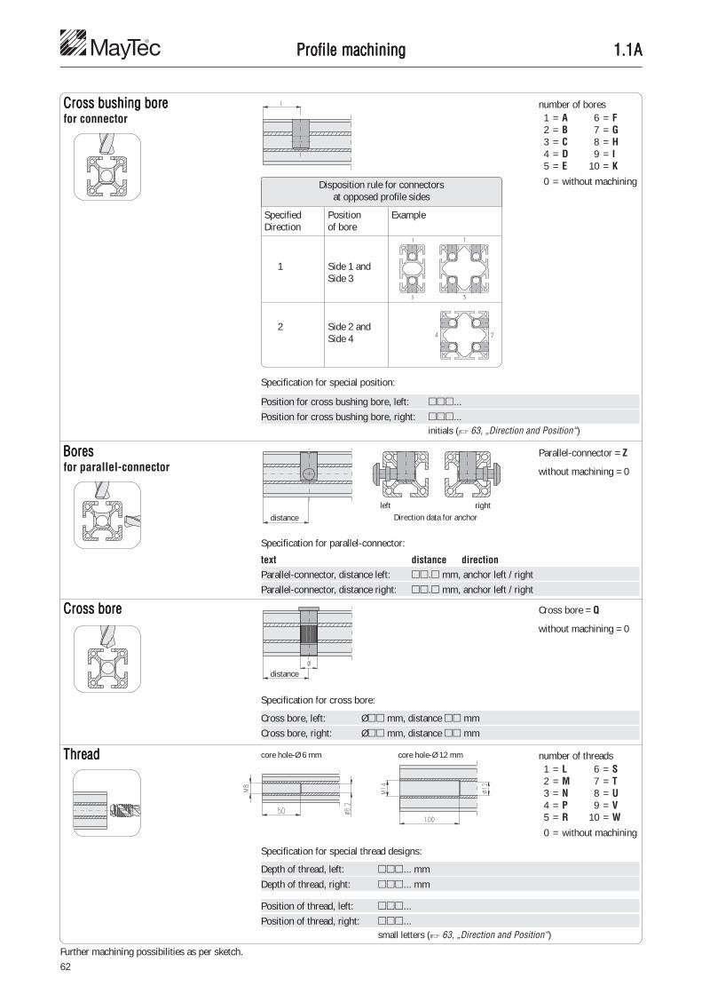
62
1.1A1.1A1.1A1.1A1.1AProfile machiningProfile machiningProfile machiningProfile machiningProfile machining
Cross bushing boreCross bushing boreCross bushing boreCross bushing boreCross bushing borefor connector
number of bores
0 = without machiningDisposition rule for connectorsat opposed profile sides
Specified Position ExampleDirection of bore
1 Side 1 andSide 3
2 Side 2 andSide 4
Specification for special position:
Position for cross bushing bore, left: ���...Position for cross bushing bore, right: ���...
initials (� 63, „Direction and Position“)
BoresBoresBoresBoresBoresfor parallel-connector
Parallel-connector = Z
without machining = 0
Specification for parallel-connector:
text distance directionParallel-connector, distance left: ��.� mm, anchor left / rightParallel-connector, distance right: ��.� mm, anchor left / right
1 = A2 = B3 = C4 = D5 = E
6 = F7 = G8 = H9 = I
10 = K
ThreadThreadThreadThreadThread
distanceleft right
Direction data for anchor
core hole-Ø 6 mm core hole-Ø 12 mm
Specification for special thread designs:
Depth of thread, left: ���... mmDepth of thread, right: ���... mm
Position of thread, left: ���...Position of thread, right: ���...
small letters (� 63, „Direction and Position“)
number of threads
0 = without machining
1 = L2 = M3 = N4 = P5 = R
6 = S7 = T8 = U9 = V
10 = W
Cross boreCross boreCross boreCross boreCross bore Cross bore = Q
without machining = 0
Specification for cross bore:
Cross bore, left: �� mm, distance �� mmCross bore, right: �� mm, distance �� mm
distance
Further machining possibilities as per sketch.

63
1
1
43
21
3
2
4
1.1A1.1A1.1A1.1A1.1A
DescriptionDirection: 1 - 4Position of slot: A - MPosition of thread: a - h
Direction and Position
View
Profile machiningProfile machiningProfile machiningProfile machiningProfile machining

64
1.1B1.1B1.1B1.1B1.1B
1V 2V 2V 2V
1V 1V 2V 2V 2V 2V 2V 2V
1G 1G 4V
1G 1G 1G 1G 2V 4V
1G 1V 1G 2V 1G 2V 4V 4V
1Q 2G 2V 2G 2V 4G 4V
1V 1Q 2G 4G
1Q 1Q 2G 2G 4G 4G
1G 1Q 1G 2G
4V
1V 2V 2V 4V 4V
1V 1V 2V 2V 2V 2V 4V 4V
1G 1V 1G 2V 1G 2V
4V 4V
1V 1V 2V 2V 2V 2V 4V 4V
-A00A00 -A00A00 -A00A00
-A00AA4 -A00AB4 -A00AB1 -A00AB4
-AA4AA4 -AB4AB4 -AB1AB1 -AB4AB4
-A00AL0 -A00AL0 -A00AD2
-AL0AL0 -AL0AL0 -AB4AD2
-AL0AA4 -AL0AB4 -AL0AB1 -AD2AD2
-A00AQ1 -AM0AB4 -AM0AB1 -AP0AD2
-AA4AQ1 -A00AM0 -A00AP0
-AQ1AQ1 -AM0AM0 -AP0AP0
-AL0AQ1 -AL0AM0 -A00C00
-A00C00 -A00C00 -A00E00 -A00CD2
-A00CA4 -A00CB4 -A00EB1 -AD2CD2
-AA4CA4 -AB4CB4 -AB1EB1 -AD1CD1
-AL0CA4 -AL0CB4 -AL0EB1 -C00C00
-C00C00 -C00C00 -E00E00 -CD2CD2
-CA4CA4 -CB4CB4 -EB1EB1 -CD1CD1
Profile machiningProfile machiningProfile machiningProfile machiningProfile machining
Coding examples for price group 1
top view
V = connector bore, G = thread, Q = cross bore

65
1
1.1B1.1B1.1B1.1B1.1B
1V 2V 2V 2V
1V 1V 2V 2V 2V 2V 2V 2V
1G 1G 4V
1G 1G 1G 1G 2V 4V
1G 1V 1G 2V 1G 2V 4V 4V
1Q 2G 2V 2G 2V 4G 4V
1V 1Q 2G 4G
1Q 1Q 2G 2G 4G 4G
1G 1Q 1G 2G
4V
1V 2V 2V 4V 4V
1V 1V 2V 2V 2V 2V 4V 4V
1G 1V 1G 2V 1G 2V
4V 4V
1V 1V 2V 2V 2V 2V 4V 4V
-F00F00 -F00F00 -F00F00
-F00FA4 -F00FB4 -F00FB1 -F00FB4
-FA4FA4 -FB4FB4 -FB1FB1 -FB4FB4
-F00FL0 -F00FL0 -F00FD2
-FL0FL0 -FL0FL0 -FB4FD2
-FL0FA4 -FL0FB4 -FL0FB1 -FD2FD2
-F00FQ1 -FM0FB4 -FM0FB1 -FP0FD2
-FA4FQ1 -F00FM0 -F00FP0
-FQ1FQ1 -FM0FM0 -FP0FP0
-FL0FQ1 -FL0FM0 -F00H00
-F00H00 -F00H00 -F00K00 -F00HD2
-F00HA4 -F00HB4 -F00KB1 -FD2HD2
-FA4HA4 -FB4HB4 -FB1KB1 -FD1HD1
-FL0HA4 -FL0HB4 -FL0KB1 -H00H00
-H00H00 -H00H00 -K00K00 -HD2HD2
-HA4HA4 -HB4HB4 -KB1KB1 -HD1HD1
Profile machiningProfile machiningProfile machiningProfile machiningProfile machining
Coding examples for price group 2
top view
V = connector bore, G = thread, Q = cross bore

66
2V
2V 2V
4V
2V 4V
4V 4V
4G 4V
4G
4G 4G
1G 4V
4V 4V
4V 4V
4V 4V
4V 4V
1.1B1.1B1.1B1.1B1.1B
-L00L00
-L00LB4
-LB4LB4
-L00LD2
-LB4LD2
-LD2LD2
-LP0LD2
-L00LP0
-LP0LP0
-L00N00
-LL0ND2
-LD2ND2
-LD1ND1
-N00N00
-ND2ND2
-ND1ND1
2V 2V 4V
2V 2V 2V 2V 4V 4V
4V 8V
4V 4V 8V 8V
2G 8G
2V 2V 2V 4V
4V 4V 2V 2V 8V 8V
2V 2V 2V 2V 4V 4V
4V 4V 4V 4V
-L00L00 -L00L00
-L00LB4 -L00LB1 �
-LB4LB4 -LB1LB1 �
-L00LD4 -L00LH2
-LD4LD4 -LH2LH2
-L00LM0 -L00LU0
-L00N00 -L00P00 -L00N00
-LB4NB4 -L00PB1 �
-LD4ND4 -LB1PB1 -LH2NH2
-N00N00 -P00P00 -N00N00
-NB4NB4 -PB1PB1 �
-ND4ND4 -ND1ND1
Article-No.. Description� 1.11.������.����� -L00LD2 Profile ������.�����
Connector position, right: CFIM (additional description)� 1.11.������.����� -LD2LD2 Profile ������.�����
Connector position, left: CFIM (additional description)Connector position, right: CFIM
� 1.11.������.����� -L00ND2 Profile ������.�����Connector position, right: CFIM (additional description)
� 1.11.������.����� -ND2ND2 Profile ������.�����Connector position, left: CFIM (additional description)Connector position, right: CFIM
Profile machiningProfile machiningProfile machiningProfile machiningProfile machining
Coding examples for price group 3
top view
V = connector bore, G = thread, Q = cross bore
Order examples for special design

67
1
1.1C1.1C1.1C1.1C1.1C
Mechanical data(Values given in the direction of the press flow)
Tensile strength Rm: min. 250 N/mm2
Elongation 0.2: min. 200 N/mm2
Pressure tension Fzul.: 95 N/mm2
Stress point A5: min. 10 %Stress point A10: min. 8 %E-Module: approx. 70,000 N/mm2
Brinell hardness: approx. 75 HB 2.5/187.5Co-efficient of elongation: 23.8 x 10⁻⁶/K
TTTTTechnical dataechnical dataechnical dataechnical dataechnical data
Extruded profileas per DIN EN 12020(fine)(Replacement for DIN 17615)
Functional length: 6,000 mmDelivery length: 6,060 mm + 10 mm
Aluminium alloy AI Mg Si 0.5 F25Material Nr. 3.3206.72 (low temp. annealed)
Surface as per DIN 17611:E6/EV1 - dull finish and anodised coloursCoat thickness approx. 10 µmCoat hardness 250-350 HVSpecial colours upon request.The surface area - subject to technicalprocedure - can show optical changes.
Profile tolerance(Excerpt from DIN EN 12020-2)
Nominal dimensions:The dimension deviation depends on theprecision with which the tooling ismanufactured, the tooling wear and thevariation during the extrusion process. Forone manufacturing setup the variation withinone profile is 0.01 mm.
Dim. range in mm Tolerance in mmfrom to
- 10 ± 0.1510 15 ± 0.2015 30 ± 0.2530 45 ± 0.3045 60 ± 0.4060 90 ± 0.4590 120 ± 0.60
120 150 ± 0.80150 180 ± 1.00180 240 ± 1.20240 300 ± 1.50
Flatness of profile surfaces In order to optimize the connection stability,all profile surfaces are designed andmanufactured with concave surfaces. Thisassures that the assembled profiles contacton the outer edges only (line of contact).When tightening the connectors the slotflanks will be drawn to the mounting profilewithin the elastic range and will keep theconnectors under tension.
Straightness toleranceof the edge in longitudinal direction
At a certain length I1 the given tolerance h1is not to be exceeded.For each incremental length of I2 = 300 mmthe deviation h2 is not to exceed 0.3 mm.
Flatness tolerance(Twist tolerance)
Width b in mm Flatness tolerance
Dim. range at length l in mfrom to to 1 1 to 2 2 to 3 3 to 4 4 to 5 5 to 6
- 25 1.0 1.5 1.5 2.0 2.0 2.025 50 1.0 1.2 1.5 1.8 2.0 2.050 75 1.0 1.2 1.2 1.5 2.0 2.075 100 1.0 1.2 1.5 2.0 2.2 2.5
100 125 1.0 1.5 1.8 2.2 2.5 3.0125 150 1.2 1.5 1.8 2.2 2.5 3.0150 200 1.5 1.8 2.2 2.6 3.0 3.5200 300 1.8 2.5 3.0 3.5 4.0 4.5
Profile tolerance
Length l1 in m Tolerance h1 in mmfrom to
- 1 0.71 2 1.32 3 1.83 4 2.24 5 2.65 6 3.0
Straightness tolerance

68
1.1C1.1C1.1C1.1C1.1C
f =
f =F · I3 + F1 · I1
2 · l + F2 · I22 · I
3E · J
F · I3
3E · J
f =F · I3
8E · J
f =F · I3
48E · J
f =5F · I3
384E · J
f =F · a2 · b2
3E · J · I
f =F · I3
192E · J
f =F · I3
384E · J
f =F · I3
(48 + ) · E · J29m
I
1
2
3
4
5
6
7
8
9
2)
TTTTTechnical dataechnical dataechnical dataechnical dataechnical data
Parallelism tolerance(Angular tolerance)
The parallelism tolerance � (angulartolerance) refers to unequal sides to theshorter side of the angle, i.e. it is measuredfrom the longer side.
Parallelism tolerance
Width b in mm max. size tolerance �from to in mm
- 30 0.330 50 0.450 80 0.580 100 0.6
100 120 0.7120 140 0.8140 160 0.9160 180 1.0180 200 1.2200 240 1.5
Bending strengthFor the computation of deflection useformulas on this page.
For the computation of deflection by theprofiles own weight, apply "Type of load"3, 6 or 9.
f = Deflection in mmF = Type of load in NI = Profile length in mmJ 1) = Moment of inertia in mm4
E = Module of elasticity in N/mm2
EAL = 70,000 N/mm2
1) Comments• Catalogue data in cm4
(Note factor of conversion 104 !)• The moments of inertia of a certain
profile are listed on the respective profilepage (� 1.09, 1.10, 1.11) and in thetables 1.1D
2) approximate value
Type of load

69
1
1.1C1.1C1.1C1.1C1.1CTTTTTechnical dataechnical dataechnical dataechnical dataechnical data
Approximate determination of deflection
To determine the approximation ofdeflection, use the diagram on this page.
Determination of deflection1. Type of load F in N2. Profile length l in mm3. Move cross point on the diagonal4. Moment of inertia of the selected
profile J in cm4
5. Cross point with the diagonal tobe vertically extended to the bottom
6. Deflection f for the specific"Type of load" in mm
Example� F = 2,000 N� l = 1,000 mm� Move cross point on the diagonal� J = 82.0 cm4 for profile 40×80, 6E� Cross point with the diagonal to
be vertically extended to the bottom� Deflection for the specific
"Type of load" in mm:
Type of load 1: f = 9.5 mmType of load 4: f = 0.6 mmType of load 8: f = 0.15 mm
Type of load 1
Type of load 4
Type of load 8
Profile length I in mm
Load
F in
N
Mom
ent o
f ine
rtia
J in
cm
4
Deflection f in mm

70
1.1D1.1D1.1D1.1D1.1D
16 F 16×40
E 16×40 16×80 16×160
20 H 20×20 20×20 20×20 20×20 20×20
F 20×10 20×30 20×30
30 F 30×30 30×30 30×30 30×30 30×30 30×30 30×30 30×30 30×50
E4
40 E3 40×40 40×40 40×40 40×40 40×40 40×40 40×40 40×60
45 E4 45×45 45×45 45×45 45×45 45×45 45×45 45×45 45×60
50 E4 50×50 50×50 50×50 50×50 50×50
60 E4 60×60 60×60 60×90
Profile selection rangeProfile selection rangeProfile selection rangeProfile selection rangeProfile selection range
Profile Ix 1) Iy 1) Wx 2) Wy 2) G 3) �
1) Ix, Iy = moment of inertia in cm4 2) Wx, Wy = moment of resistance in cm3 3) G = weight in kg/m
PG slot
Design
Profile Ix 1) Iy 1) Wx 2) Wy 2) G 3) �60×60, 2E, LP 35.1 37.7 11.7 12.5 2.9 32
2E, SP 55.9 58.5 18.6 19.5 4.3 3220×20, 3H, SP 0.9 0.9 0.9 0.9 0.65 1330×30, 3F, LP 3.3 3.2 2.2 2.2 0.9 17
3F, SP 3.5 3.7 2.4 2.4 1.1 173F, L 3.3 3.2 2.2 2.2 0.9 343F, S 3.5 3.7 2.4 2.4 1.1 34
40×40, 3E, LP 9.4 10.0 4.7 5.0 1.5 213E, L 8.3 8.8 4.1 4.4 1.4 363E, S 12.0 12.3 6.0 6.0 2.0 36
45×45, 3E, LP 14.0 14.7 6.2 6.5 2.1 2950×50, 3E, L 18.4 16.0 7.3 5.8 1.9 42
3E, S 27.3 28.2 11.1 11.1 3.1 4220×20, 4H, LP 0.8 0.8 0.8 0.8 0.53 14
4H, SP 0.9 0.9 0.9 0.9 0.62 1430×30, 4F, LP 3.3 3.3 2.2 2.2 0.9 17
4F, SP 3.5 3.5 2.4 2.4 1.1 174F, L 3.3 3.3 2.2 2.2 0.9 354F, S 3.5 3.5 2.4 2.4 1.1 35
40×40, 4E, LP 9.9 9.9 4.9 4.9 1.5 214E, SP 12.0 12.0 6.0 6.0 2.0 214E, L 9.9 9.9 4.9 4.9 1.5 374E, S 12.0 12.0 6.0 6.0 2.0 37
45×45, 4E, LP 13.5 13.5 6.0 6.0 1.9 294E, SP 15.5 15.5 6.9 6.9 2.1 294E, L 13.5 13.5 6.0 6.0 1.9 404E, S 16.8 16.8 7.4 7.4 2.3 40
50×50, 4E, L 19.2 19.2 7.7 7.7 2.2 434E, S 27.3 27.3 11.0 11.0 3.1 43
60×60, 4E, LP 35.5 35.5 11.7 11.7 2.7 324E, SP 56.0 56.0 18.7 18.7 4.2 324E, L 35.5 35.5 11.7 11.7 2.7 444E, S 56.0 56.0 18.7 18.7 4.2 44
45×60, 4E, LP 26.5 16.0 9.0 7.2 2.3 294E, SP 38.0 23.5 13.0 10.4 3.0 294E, L 26.5 16.0 9.0 7.2 2.3 404E, S 38.8 23.5 13.0 10.4 3.0 40
40×60, 0E, LP 27.7 13.1 9.3 6.5 2.1 21
20×30, 1F, LP 2.2 1.4 1.5 1.4 0.7 15
20×30, 2F, LP 2.2 1.5 1.5 1.5 0.74 152F, SP 2.6 1.9 1.7 1.7 1.0 15
60×90, 6E, L 124.0 54.0 27.5 18.0 4.0 446E, S 193.0 83.0 43.0 27.5 6.0 44
30×50, 4F, L 11.0 4.3 4.8 3.3 1.3 354F, S 16.9 6.6 6.7 4.4 2.0 35
16×40, 1F, LP 4.4 0.8 2.2 0.8 0.87 121F, SP 5.3 1.0 2.7 1.0 1.0 12
16×40, 1E, LP 4.3 0.8 2.2 0.8 0.75 121E, SP 7.2 1.1 3.6 1.1 1.14 12
16×80, 2E, LP 30.7 1.6 7.7 1.6 1.49 122E, SP 48.3 2.2 12.0 2.2 2.11 12
16×160, 4E, LP 221.0 3.2 27.5 3.2 2.6 12
20×10, 1F, LP 0.1 0.6 0.2 0.5 0.35 15
20×20, 2H, soft, SP 0.6 0.6 0.6 0.6 0.52 1330×30, 2F, soft, SP 2.7 2.7 1.6 1.6 0.9 16
2F, soft, S 2.7 2.7 1.6 1.6 0.9 3440×40, 2E, soft, LP 6.4 6.4 3.8 3.8 1.2 20
2E, soft, L 6.4 6.4 3.8 3.8 1.2 3645×45, 2E, soft, LP 11.4 11.4 5.1 5.1 1.6 2850×50, 2E, soft, S 18.8 18.8 7.5 7.5 2.3 42
30×30, 0F, SP 4.4 4.4 2.3 2.3 1.3 1640×40, 0E, SP 12.0 12.0 6.0 6.0 1.8 2045×45, 0E, LP 15.5 15.5 6.9 6.9 2.2 2830×30, 1F, LP 3.1 3.1 2.1 2.1 0.9 16
1F, SP 4.3 4.0 2.9 2.6 1.2 1640×40, 1E, LP 8.5 8.1 4.1 4.0 1.3 2045×45, 1E, LP 14.7 15.5 6.5 6.8 2.1 2830×30, 2F, cor., S 3.7 3.7 2.4 2.4 1.1 34
20×20, 2H, cor., SP 1.0 1.0 0.9 0.9 0.68 1330×30, 2F, cor., LP 3.2 3.2 2.1 2.1 0.9 16
2F, cor., SBP 3.7 3.7 2.4 2.4 1.1 162F, cor., L 3.2 3.2 2.1 2.1 0.9 342F, cor., SB 3.7 3.7 2.4 2.4 1.1 34
40×40, 2E, cor., LP 8.0 8.0 4.0 4.0 1.3 202E, cor., SP 12.0 12.0 6.0 6.0 2.0 202E, cor., L 8.0 8.0 4.0 4.0 1.3 362E, cor., S 12.3 12.3 6.1 6.1 2.0 36
45×45, 2E, cor., LP 14.7 14.7 6.6 6.6 2.0 2850×50, 2E, cor., L 16.5 16.5 6.7 6.7 1.7 42
2E, cor., S 28.2 28.2 11.1 11.1 3.2 4220×20, 2H, LP 1.0 0.8 1.0 0.8 0.58 1330×30, 2F, LP 3.2 3.2 2.1 2.1 0.9 17
2F, SP 3.6 3.9 2.4 2.6 1.1 172F, L 3.2 3.2 2.2 2.2 0.9 34
40×40, 2E, LP 8.2 7.5 4.1 3.8 1.3 212E, L 8.2 7.5 4.1 3.8 1.3 36
45×45, 2E, LP 14.0 15.5 6.2 6.9 2.0 2950×50, 2E, L 17.7 13.6 7.0 5.4 1.6 42

71
1
1.1D1.1D1.1D1.1D1.1D
16 F
E
20 H 20×40 20×40
F
30 F 30×60 30×60 30×100 30×100 30×100 30×150
E4 30×100 30×150
40 E3 40×80 40×80 40×80 40×80 40×80 40×80 40×120 40×160 40×160
45 E4 45×90 45×90
50 E4 50×100 50×100 50×150
60 E4
Profile selection rangeProfile selection rangeProfile selection rangeProfile selection rangeProfile selection range
1) Ix, Iy = moment of inertia in cm4 2) Wx, Wy = moment of resistance in cm3 3) G = weight in kg/m
PG slot
Design
Profile Ix 1) Iy 1) Wx 2) Wy 2) G 3) � Profile Ix 1) Iy 1) Wx 2) Wy 2) G 3) �30×60, 0F, SP 29.0 7.8 9.6 5.2 2.2 1740×80, 0E, LP 66.8 18.4 16.7 9.2 2.7 2145×90, 0E, LP 107.5 30.4 23.9 13.5 3.6 29
0E, SP 134.3 36.3 29.8 16.2 4.7 2940×80, 3E, cor., LP 65.2 17.9 16.3 8.9 2.6 22
20×40, 4H, SP 7.0 2.0 3.5 2.0 1.3 14
40×80, 4E, LP 64.0 17.9 16.0 8.9 2.6 224E, L 63.2 17.8 15.7 8.9 2.6 37
40×80, 4E, LBP 74.5 18.3 18.6 9.2 2.8 22
40×80, 5E, LP 72.2 18.1 18.0 9.0 2.8 22
20×40, 6H, LP 5.3 1.4 2.6 1.4 0.9 146H, SP 6.4 1.7 3.2 1.7 1.3 14
30×60, 6F, LP 21.2 5.7 7.0 3.8 1.6 176F, SP 25.0 7.0 8.3 4.7 2.1 176F, L 21.2 5.7 7.0 3.8 1.6 356F, S 32.0 8.0 10.9 5.4 2.1 35
40×80, 6E, LP 62.7 17.7 15.6 8.8 2.5 236E, SP 82.0 23.4 20.5 11.7 3.8 236E, XP 90.0 27.0 22.5 13.5 4.4 236E, L 62.7 17.0 15.6 8.5 2.6 376E, S 82.0 23.4 20.5 11.7 3.8 37
45×90, 6E, LP 98.0 27.5 21.8 12.2 3.3 306E, SP 126.0 34.0 28.0 15.0 4.4 306E, L 98.0 27.5 21.8 12.2 3.3 406E, S 126.0 34.0 28.0 15.0 4.4 40
50×100, 6E, L 138.0 37.0 27.5 14.5 3.5 436E, S 202.0 57.2 40.4 22.8 5.9 43
50×100, 8E, L 137.0 40.0 27.5 16.0 4.0 4350×100, 8E, S 200.0 53.3 39.9 21.3 6.0 43
40×120, 8E, L 194.0 26.0 33.0 13.0 3.7 3750×150, 8E, S 628.0 83.0 83.0 33.0 8.1 43
30×100, 5E, 2F, SP 108.9 12.4 21.7 8.3 3.5 18
30×100, 8F, SP 115.0 11.6 22.9 7.7 3.4 18
30×100, 9F, SP 130.6 11.9 25.9 7.9 3.6 18
30×100, 10F, SP 127.0 11.9 25.4 7.9 3.6 19
40×160, 6E, LP 450.4 36.3 56.3 18.1 5.0 23
40×160, 10E, LP 433.5 33.1 54.2 16.5 4.7 23
30×150, 8F, SP 340.0 16.0 45.0 11.0 4.1 19
30×150, 8E, SP 481.0 25.1 64.1 16.7 7.9 19

72
1.1D1.1D1.1D1.1D1.1D
16 F
E
20 H 40×40
F
30 F 60×60 60×60 60×60
E4
40 E3 80×80 80×80 80×80 80×80 80×80 80×80 80×80 80×120 80×160 80×160 80×160 120×120
45 E4 90×90 90×90
50 E4 100×100 100×100 100×200
60 E4
Profile selection rangeProfile selection rangeProfile selection rangeProfile selection rangeProfile selection range
1) Ix, Iy = moment of inertia in cm4 2) Wx, Wy = moment of resistance in cm3 3) G = weight in kg/m
PG slot
Design
Profile Ix 1) Iy 1) Wx 2) Wy 2) G 3) � Profile Ix 1) Iy 1) Wx 2) Wy 2) G 3) �60×60, 0F, SP 58.2 58.2 15.5 15.5 4.0 1980×80, 0E, LP 135.0 135.0 33.5 33.5 4.7 24
80×80, 4E, cor., LP 128.0 128.0 32.0 32.0 4.5 24
80×80, 6E, LP 121.3 116.0 30.3 29.0 4.2 24
80×80, 7E, SP 173.0 160.0 43.3 40.0 7.6 2480×80, 7E, SBP 145.0 141.0 36.2 35.2 5.3 24
40×40, 8H, LP 10.0 10.0 5.0 5.0 1.5 1460×60, 8F, L 38.7 38.7 12.9 12.9 2.6 3580×80, 8E, LP 114.0 114.0 28.4 28.4 4.1 24
8E, SP 166.0 166.0 41.4 41.4 5.9 248E, L 111.0 111.0 28.0 28.0 3.7 388E, S 166.0 166.0 41.4 41.4 5.9 38
90×90, 8E, LP 190.5 190.5 42.3 42.3 5.6 308E, L 183.0 183.0 40.7 40.7 5.3 40
100×100, 8E, S 411.0 411.0 82.0 82.0 9.7 4380×80, 8E, LB 115.0 115.0 29.0 29.0 4.5 3890×90, 8E, SP 282.0 282.0 63.0 63.0 9.5 30
8E, S 282.0 282.0 63.0 63.0 9.5 40100×100, 8E, L 284.0 284.0 50.8 50.8 6.2 4360×60, 8F, angle, S 35.2 35.2 9.9 9.9 2.8 3580×80, 8E, angle, S 120.0 120.0 23.8 23.8 6.3 38
80×120, 10E, SP 449.9 217.8 72.6 54.4 8.6 25
80×160, 8E, SP 944.0 183.0 118.0 45.8 7.9 25
80×160, 8E, LP 828.0 259.0 104.0 65.0 8.6 25
80×160, 12E, SP 883.0 269.0 110.0 67.3 9.4 2412E, L 801.0 235.0 100.0 59.0 8.8 3812E, S 880.0 268.0 110.0 67.0 9.4 38
100×200, 12E, SP 2,450.0 760.0 250.0 152.0 17.2 31
120×120, 12E, SP 624.0 624.0 104.0 104.0 10.6 25

73
1
1.1D1.1D1.1D1.1D1.1DProfile selection rangeProfile selection rangeProfile selection rangeProfile selection rangeProfile selection range
1) Ix, Iy = moment of inertia in cm4 2) Wx, Wy = moment of resistance in cm3 3) G = weight in kg/m
PG slot
Design
Profile Ix 1) Iy 1) Wx 2) Wy 2) G 3) �40×40, 2E, 45°, LP 7.3 7.3 3.9 3.9 1.4 27
80×80, 3E, 45°, LP 105.0 105.0 26.0 26.0 4.1 27
80×80, 7E, 45°, LP 99.3 99.3 24.8 24.8 4.0 27
40, round 30°, 2F, LP 6.0 4.8 3.0 2.4 1.2 262F, L 6.0 4.8 3.0 2.4 1.2 39
40, round 45°, 2E, LP 14.5 8.0 4.9 3.7 1.6 262E, L 14.5 8.0 4.9 3.7 1.6 39
40, round 60°, 2E, LP 30.0 10.5 7.6 4.6 1.9 262E, L 30.0 10.5 7.6 4.6 1.9 39
Profile Ix 1) Iy 1) Wx 2) Wy 2) G 3) �40, round 90°, 2E, LP 89.0 89.0 16.0 16.0 3.0 26
2E, L 89.0 89.0 16.0 16.0 3.0 39
48, round, 1E, SP 12.5 12.9 4.9 5.4 1.8 33
48, round, 2E, cor., SP 12.0 12.0 5.0 5.0 2.0 33
48, round, 2E, SP 12.5 13.5 5.1 5.9 2.0 33
30, hexag., 6F, SP 32.0 32.0 9.8 9.8 2.8 3340, hexag., 6E, SP 83.0 83.0 21.0 21.0 4.4 33
30, octag., 8F, SP 84.0 84.0 21.0 21.0 3.9 3340, octag., 8E, SP 233.0 233.0 44.0 44.0 6.5 33
16 F
E
20 H
F
30 F 30×30 30×30 30×30 30×30 30×45 30×50 30×50
E4
40 E3 40×40 40×40 40×40 40×60 40×60 60×80 60×80
45 E4
50 E4 50×50 50×50
60 E4
PG slot
Design
Profile Ix 1) Iy 1) Wx 2) Wy 2) G 3) � Profile Ix 1) Iy 1) Wx 2) Wy 2) G 3) �
16 F
E
20 H
F
30 F 30 hexag. 30 octag.
E4
40 E3 40×40 80×80 80×80 40×30° 40×45° 40×60° 40×90° 40 hexag. 40 octag.
45 E4
50 E4 48 round 48 round 48 round
60 E4
30×30, 0F, P, LP 3.8 3.8 2.4 2.4 1.10 45
30×30, 2F, P, LP 5 4.3 3.3 2.8 2.2 1.20 452F, P, LP 6 3.6 2.8 2.4 1.9 1.00 45
30×30, 2F, WG, LP 7.5 2.6 3.2 1.7 2.1 0.86 4840×40, 2E, WG, LP 7.5 7.5 8.2 3.8 4.1 1.35 48
30×30, 2F, c., P, LP 4 3.3 3.3 2.2 2.2 1.00 4540×40, 2E, c., P, LP 4 10.3 10.3 5.2 5.2 1.80 4650×50, 2E, c., P, LP 4 25.2 25.2 10.6 7.3 2.40 47
30×30, 3F, P, LP 4 3.3 2.8 2.2 1.8 0.90 4540×40, 3E, P, LP 4 10.2 8.7 5.1 4.3 1.65 46
50×50, 3E, P, LP 4 23.5 20.9 9.9 8.7 2.60 47
30×45, 2F, WG, LP 7.5 4.3 7.4 2.9 3.3 1.15 4840×60,2E,1F,WG,LP 7.5 12.2 22.5 6.1 7.5 1.97 48
30×50, 2F, P, LP 5 7.0 14.7 4.7 5.9 1.90 45
30×50, 3F, P, LP 4 5.5 11.8 3.6 4.8 1.5 4540×60, 3E, P, LP 4 14.8 26.3 7.4 8.8 2.4 46
60×80, 5E, P, LP 4 100.4 50.4 25.1 16.8 3.8 46
60×80, 6E, P, LP 4 85.8 50.8 21.5 16.9 3.7 46

74
1.1E.011.1E.011.1E.011.1E.011.1E.01Profile applicationsProfile applicationsProfile applicationsProfile applicationsProfile applications
Profile combinationsProfile combinationsProfile combinationsProfile combinationsProfile combinations With the MayTec Connector System it ispossible to make a multitude of form-matching and stable profile combinations.
Special slitsSpecial slitsSpecial slitsSpecial slitsSpecial slits Panel elements can be set in the profile flushto the outer edge for form-matching design.The slits needed for that can be made innearly all profiles.

75
1
1.1E.021.1E.021.1E.021.1E.021.1E.02Profile applicationsProfile applicationsProfile applicationsProfile applicationsProfile applications
ApplicationProfiles to construct slot plates of anyrequired size
Slot platesSlot platesSlot platesSlot platesSlot plates
F-slot, slot distance 25 mm
F-slot, slot distance 50 mm
E-slot, slot distance 25 mm (on top),100 mm (on buttom)
E-slot, slot distance 50 mm
F-slotF-slotF-slotF-slotF-slot
E-slotE-slotE-slotE-slotE-slot

76
1.1E.021.1E.021.1E.021.1E.021.1E.02Profile applicationsProfile applicationsProfile applicationsProfile applicationsProfile applications
machining data � Profile machining 1.1A
Slot plates F-slotSlot plates F-slotSlot plates F-slotSlot plates F-slotSlot plates F-slotSlot distance 50 mm
Single partsanchor 1.21.A5F5cross bushing 1.21.B30
Drill dimensionsProfile 30×150, 8F, SP
Description Weight Article-No.Profile 30×150, 8F, SP bar 6 m 4.1 kg/m 1.11.030150.85SP.60
Slot plates F-slotSlot plates F-slotSlot plates F-slotSlot plates F-slotSlot plates F-slotSlot distance 25 mm
Single partsanchor 2.21.A10F5cross bushing 2.21.B10
Drill dimensions
Profile 30×100, 9F, SP
Description Weight Article-No.Profile 30×100, 9F, SP bar 6 m 3.6 kg/m 1.11.030100.94SP.60
Profile 30×100, 10F, SP
Description Weight Article-No.Profile 30×100, 10F, SP bar 6 m 3.6 kg/m 1.11.030100.104SP.60

77
1
1.1E.021.1E.021.1E.021.1E.021.1E.02Profile applicationsProfile applicationsProfile applicationsProfile applicationsProfile applications
Slot plates E-slotSlot plates E-slotSlot plates E-slotSlot plates E-slotSlot plates E-slotSlot distance 25 mm
Single partsanchor 1.21.A5F5cross bushing 1.21.B24
Drill dimensions
Profile 30×100, 5E, 2F, SP
Description Weight Article-No.Profile 30×100, 5E, 2F, SP bar 6 m 3.5 kg/m 1.11.030100.74SP.60
machining data � Profile machining 1.1A
Slot plates E-slotSlot plates E-slotSlot plates E-slotSlot plates E-slotSlot plates E-slotSlot distance 50 mm
Single partsanchor 1.21.A2E5cross bushing 1.21.B34
Drill dimensionsProfile 30×150, 8E, SP
Description Weight Article-No.Profile 30×150, 8E, SP bar 6 m 7.9 kg/m 1.11.030150.84SP.60

78
1.1E.031.1E.031.1E.031.1E.031.1E.03
1.21.3E11.21.4E1
1.21.3EK11.21.4EK1
Profile applicationsProfile applicationsProfile applicationsProfile applicationsProfile applications
Hand railHand railHand railHand railHand rail ApplicationHand rail for balustrades on stairs andplatforms
Hand rail straight Hand rail angled
Hand rail tilted Hand rail tilted and angled
Working dimensions for hand rail straightwith radius compensation
CommentsAngled joints: 0 deg. to 90 deg.Incline: 0 deg. to 45 deg.
Working dimensions for hand rail straight,tilted and/or angled without radiuscompensation (milled)

79
1
1.1E.041.1E.041.1E.041.1E.041.1E.04Profile applicationsProfile applicationsProfile applicationsProfile applicationsProfile applications
U-Profile 40U-Profile 40U-Profile 40U-Profile 40U-Profile 40 ApplicationFor the construction of height adjustableframes on 40×40 and 40×80 profile bases
Description Weight Article-No.U-Profile 40 bar 6 m 1.35 kg/m 1.19.14440.60

80
1.1E.051.1E.051.1E.051.1E.051.1E.05Profile applicationsProfile applicationsProfile applicationsProfile applicationsProfile applications
Profiles for cable guideProfiles for cable guideProfiles for cable guideProfiles for cable guideProfiles for cable guide ApplicationFor running cables or pneumatic hoses.All chamber profiles can be delivered withopen slots.
Cover is carried out by cover profiles:
Cover profile PVC 1.41.11�Cover profile ALU 1.41.121
Application of cross braces to stabilizeslotted profiles
CommentsProfiles for cable guide see list at profilepre-cut lid
Order details
Order example Order requestProfile 40×80 mm, 6 E-slots, heavy, 8 mm slotted for cable guide, length 4.5 m
OrderProfile 40×80, 6E S, for cable guide, slotted 8 mm 1.12.040080.65S-F00F00/4500
machining data � Profile machining 1.1A
Description Article-No.Profile ������ for cable guide, slotted 8 mm 1.12.������.��

81
1
1.1E.061.1E.061.1E.061.1E.061.1E.06
30×60
60×60
Profile applicationsProfile applicationsProfile applicationsProfile applicationsProfile applications
Profiles for cable guideProfiles for cable guideProfiles for cable guideProfiles for cable guideProfiles for cable guideSlot distance 30
ApplicationFor running cables or pneumatic hoses. Allchamber profiles can be delivered with openslots.
Milled section on the pre-cut lid forfastening with T-Nut in F-slot
machining data � Profile machining 1.1A
Order details
Order example Order requestProfile 30×60 mm, 6 F-slots, heavy, 10 mm slotted for cable guide, length 4.5 m
OrderProfile 30×60, 6F S, for cable guide, slotted 10 mm 1.13.030060.65S-A00A00/4500
Description Article-No.Profile ������ for cable guide, slotted 10 mm 1.13.������.��
Profile pre-cut lid 30Profile pre-cut lid 30Profile pre-cut lid 30Profile pre-cut lid 30Profile pre-cut lid 30
Single parts• countersunk screw DIN 7991, M5×8 0.63.D07991.05008• threaded plate F, M5 1.31.FM5• T-Nut for subsequent insertion F, M5 1.32.4FM5
Description Weight Article-No.Profile pre-cut lid 30 0.49 kg/m 1.19.110130
Profiles for cable guide, slot distance 30
0F SP
0F SP 6F S6F L
8F L 8F angle S
Profile light, plain heavy, plain light heavy
6F LP 6F SP

82
1.1E.061.1E.061.1E.061.1E.061.1E.06
40×160 80×160 40×120 80×160 80×16080×120
40×80
80×80
80×160 120×120
Profile applicationsProfile applicationsProfile applicationsProfile applicationsProfile applications
Profiles for cable guideProfiles for cable guideProfiles for cable guideProfiles for cable guideProfiles for cable guideSlot distance 40
ApplicationFor running cables or pneumatic hoses. Allchamber profiles can be delivered with openslots.
machining data � Profile machining 1.1A
Order details
Order example Order requestProfile 80×80 mm, 8 E-slots, heavy, 14 mm slotted for cable guide, length 4.5 m
OrderProfile 80×80, 8E S, for cable guide, slotted 14 mm 1.13.080080.83S-L00L00/4500
Description Article-No.Profile ������ for cable guide, slotted 14 mm 1.13.������.��
Profile pre-cut lid 40Profile pre-cut lid 40Profile pre-cut lid 40Profile pre-cut lid 40Profile pre-cut lid 40
Single parts• countersunk screw DIN 7991, M6×14 0.63.D07991.06014• threaded plate E, M6 1.31.EM6• T-Nut for subsequent insertion E, M6 1.32.4EM6
Description Weight Article-No.Profile pre-cut lid 40 0.74 kg/m 1.19.110140
Profiles for cable guide, slot distance 40
Profile light, plain heavy, P light heavy
0E LP 4E c. LP 6E LP 8E LP
3E 45° LP 7E 45° LP
0E LP 3E c.LP 4E LP 4E LBP 5E LP 6E LP
6E LP 8E LP
4E L 6E L
8E L
8E L 8E LB
12E L
6E S
8E S
12E S
8E angle S
6E SP
7E SP
8E SP
10E SP 12E SP 12E SP10E LP

83
1
1.1E.061.1E.061.1E.061.1E.061.1E.06
30×100 30×150 100×200 50×100 50×150 100×10050×100 100×100
Profile applicationsProfile applicationsProfile applicationsProfile applicationsProfile applications
Profiles for cable guideProfiles for cable guideProfiles for cable guideProfiles for cable guideProfiles for cable guideSlot distance 50
ApplicationFor running cables or pneumatic hoses. Allchamber profiles can be delivered with openslots.
machining data � Profile machining 1.1A
Profile pre-cut lid 50Profile pre-cut lid 50Profile pre-cut lid 50Profile pre-cut lid 50Profile pre-cut lid 50
Order details
Order example Order requestProfile 50×100 mm, 6 E-slots, heavy, 14 mm slotted for cable guide, length 4.5 m
OrderProfile 50×100, 6E S, for cable guide, slotted 14 mm 1.13.050100.65S-F00F00/4500
Description Article-No.Profile ������ for cable guide, slotted 14 mm 1.13.������.��
Description Weight Article-No.Profile pre-cut lid 50 0.85 kg/m 1.19.110150
Single partsF-slot• countersunk screw DIN 7991, M5×8 0.63.D07991.05008• threaded plate F, M5 1.31.FM5• T-Nut for subsequent insertion F, M5 1.32.4FM5E-slot• countersunk screw DIN 7991, M6×14 0.63.D07991.06014• threaded plate E, M6 1.31.EM6• T-Nut for subsequent insertion E, M6 1.32.4EM6
8F SP 8F SP 12E SP 6E S 8E S 8E S6E L 8E L
Profiles for cable guide, slot distance 50
heavy, plain light heavy

84
1.1E.071.1E.071.1E.071.1E.071.1E.07Profile applicationsProfile applicationsProfile applicationsProfile applicationsProfile applications
A B C D E F G H I K L M A B C D E F G H I K L M A B C D E F G H I K L M
1.11.030060.64LP 30 30×60, 6F, LP 7001.11.030060.65S 30×60, 6F, S 7001.11.030060.65SP 30×60, 6F, SP 7001.11.030100.74SP 30×100, 5E, 2F, SP 7001.11.030100.84SP 30×100, 8F, SP 7001.11.030100.94SP 30×100, 9F, SP 7001.11.030100.104SP 30×100, 10F, SP 700
1.11.040040.03SP 40 40×40, 0E, LP 7001.11.040040.13LP 40×40, 1E, LP 7001.11.040040.22S 40×40, 2E, cor., S 7001.11.040040.22L 40×40, 2E, cor., L 7001.11.040040.22LP 40×40, 2E, cor., LP 7001.11.040040.22SP 40×40, 2E, cor., SP 7001.11.040040.23L 40×40, 2E, L 7001.11.040040.23LP 40×40, 2E, LP 7001.11.040040.33S 40×40, 3E, S 7001.11.040040.33L 40×40, 3E, L 7001.11.040040.33LP 40×40, 3E, LP 7001.11.040040.43S 40×40, 4E, S 7001.11.040040.43L 40×40, 4E, L 7001.11.040040.43LP 40×40, 4E, LP 7001.11.040040.43SP 40×40, 4E, SP 7001.11.040060.04LP 40×60, 0E, LP 7001.11.040080.04LP 40×80, 0E, LP 7001.11.040080.44L 40×80, 4E, L 7001.11.040080.64L 40×80, 6E, L 7001.11.040080.65S 40×80, 6E, S 7001.11.040080.32LP 40×80, 3E, cor., LP 7001.11.040080.44LP 40×80, 4E, LP 7001.11.040080.44LBP 40×80, 4E, LBP 7001.11.040080.54LP 40×80, 5E, LP 7001.11.040080.64LP 40×80, 6E, LP 7001.11.040080.64SP 40×80, 6E, SP 700
1.11.048R00.10SP 48, round, 1E, SP 1.5001.11.048R00.20SP 48, round, 2E, SP 1.5001.11.048R00.22SP 48, round, 2E, cor., SP 1.500
1.09.016040.14SP 16 16×40, 1E, SP 4001.10.016040.14LP 16×40, 1F, LP 4001.10.016040.14SP 16×40, 1F, SP 400
1.10.020020.21SP 20 20×20, 2H, soft, SP 7001.10.020020.22SP 20×20, 2H, cor., SP 7001.10.020020.23LP 20×20, 2H, LP 7001.10.020020.33SP 20×20, 3H, SP 7001.10.020020.43LP 20×20, 4H, LP 7001.10.020020.43SP 20×20, 4H, SP 7001.11.020010.14LP 20×10, 1F, LP 4001.11.020030.14LP 20×30, 1F, LP 7001.11.020030.24LP 20×30, 2F, LP 7001.11.020030.24SP 20×30, 2F, SP 700
1.11.030030.03SP 30 30×30, 0F, SP 7001.11.030030.13LP 30×30, 1F, LP 7001.11.030030.13SP 30×30, 1F, SP 7001.11.030030.22S 30×30, 2F, cor., S 7001.11.030030.22SB 30×30, 2F, cor., SB 7001.11.030030.22SBP 30×30, 2F, cor., SBP 7001.11.030030.22L 30×30, 2F, cor., L 7001.11.030030.22LP 30×30, 2F, cor., LP 7001.11.030030.23L 30×30, 2F, L 7001.11.030030.23LP 30×30, 2F, LP 7001.11.030030.23SP 30×30, 2F, SP 7001.11.030030.33S 30×30, 3F, S 7001.11.030030.33L 30×30, 3F, L 7001.11.030030.33LP 30×30, 3F, LP 7001.11.030030.33SP 30×30, 3F, SP 7001.11.030030.43S 30×30, 4F, S 7001.11.030030.43L 30×30, 4F, L 7001.11.030030.43LP 30×30, 4F, LP 7001.11.030030.43SP 30×30, 4F, SP 7001.11.030050.44S 30×50, 4F, S 7001.11.030050.44L 30×50, 4F, L 7001.11.030060.04SP 30×60, 0F, SP 7001.11.030060.64L 30×60, 6F, L 700
Article-No. PG Profile min. inside-Ø Article-No. PG Profile min. inside-Ø
CurCurCurCurCurved prved prved prved prved profilesofilesofilesofilesofiles
For curved profiles the following data areneeded:
• Profile (current conditions see tablebelow)
• Position of profile � 61• Radius• Direction � 63• Accuracy to size for profile elements and
for profile functions
Function ‘T- Nut’ Function ‘threaded plate’ Function ‘connector’position of slot(s) position of slot(s) position of slot(s) position of core hole(s)
a b c d e f g h
The marking of the slots and core holes takes place in accordance with the marking for ‘the profile machining’ � 1.1A
Position of profile

85
2
1.21.21.21.21.2Connection SystemConnection SystemConnection SystemConnection SystemConnection System
The different direction angles of leadof thread and clamping cone preventthe loosening of the connection byvibration.
The proven connection system!The MayTec quick-connection systemallows combination of all MayTecprofiles in any wayimaginable.It carries same stability out after all foursides.
The connection allows:• easy machining• quick assembly• innumerable (dis)assemblies
The connection system is:• complete• stable• functional
SimpleSimpleSimpleSimpleSimple
QuickQuickQuickQuickQuick
EconomicalEconomicalEconomicalEconomicalEconomical
FunctionalFunctionalFunctionalFunctionalFunctional
Vibration proofVibration proofVibration proofVibration proofVibration proof

86
1.21.21.21.21.2
Stability S-Class
MayTecUniversal-Connector
18,000Nworking load
Connection SystemConnection SystemConnection SystemConnection SystemConnection System
Vibration
proof

87
2
1.21.21.21.21.2Connectors - ExamplesConnectors - ExamplesConnectors - ExamplesConnectors - ExamplesConnectors - Examples
MayTec universal-connector
MayTec standard-connector
MayTec screw-type connector MayTec screw-type connector
MayTec ground-connector for potential equalisation
MayTec connector with square head
The MayTec universal-connector allows:
• any desired position of profiles• only one type for 0° and 90° position of
cross bushing• simple determination of the
connector type• minimisation of stock keeping Cross bushing
Anchor
The MayTec standard-connector allows subsequent front-sidedmounting or dismounting in any location.
Anchor
Cross bushing
The MayTec screw-type connector allows connection to threadedholes in plates.
The MayTec screw-type connector allows connection to profilesby means of T-Nuts.
Anchor
Cross bushing
T-Nut
Anchor
Crossbushing
The MayTec connector with square head offers the highest loadbearing capacity.
The MayTec ground-connector allows potential equalisationbetween two profiles. When the connector is tightened, theserration at the rear of the anchor head penetrates the anodisedprofile coating and thus provides an electrical contact.
Deliverable types � Connectors 1.2AGround connections � 1.70
contact
Anodised coating
Cross bushing
Anchor

88
1.21.21.21.21.2SummarSummarSummarSummarSummary: Connectors (with machining)y: Connectors (with machining)y: Connectors (with machining)y: Connectors (with machining)y: Connectors (with machining)
Standard � 94, 96
Oblique � 94, 96 Oblique-cross � 97 Extension / Parallel � 111
Miter � 94, 99 Shifter � 99 Extension � 94, 98
Screw-type � 95, 100
Crossbushing bore
The MayTThe MayTThe MayTThe MayTThe MayTec Connector Systemec Connector Systemec Connector Systemec Connector Systemec Connector System• mounting of connector in core hole• with machining
Anchor
Cross bushing
Cross bushingbore
with retaining plate � 134
Clamping lever � 137
Anti-twist devices
Clamping lever for connectors
with T-Nut � 145-148
Parallel � 94, 98

89
2
1.21.21.21.21.2SummarSummarSummarSummarSummary: Connectors (with machining)y: Connectors (with machining)y: Connectors (with machining)y: Connectors (with machining)y: Connectors (with machining)
Connector screw,self-cutting � 101, 116
Connector screw
� 101
Threaded insert with lenshead screw � 1.35
Cross bore
Thread
Screw-type connectionsScrew-type connectionsScrew-type connectionsScrew-type connectionsScrew-type connections• with machining
Tool Connectorscrew
Cross bore
Thread Thread
Clamping connectionsClamping connectionsClamping connectionsClamping connectionsClamping connections• with machining
Clamping connector � 123
Threaded insert
Clamping connector Thread
ST-Connector � 114-115SE-Connector � 113
The MayTThe MayTThe MayTThe MayTThe MayTec Connector Systemec Connector Systemec Connector Systemec Connector Systemec Connector System• mounting of connector in slot• with machining
Crossbushing bore

90
1.21.21.21.21.2SummarSummarSummarSummarSummary: Connectors (without machining)y: Connectors (without machining)y: Connectors (without machining)y: Connectors (without machining)y: Connectors (without machining)
Parallel connector � 122
The MayTThe MayTThe MayTThe MayTThe MayTec Connector Systemec Connector Systemec Connector Systemec Connector Systemec Connector System• Parallel connector• without machining
Standard � 117
The MayTThe MayTThe MayTThe MayTThe MayTec Connector Systemec Connector Systemec Connector Systemec Connector Systemec Connector System• Connector kits• without machining
Parallel � 118
Connecting block
Connector screw,self-cutting
Setscrew
T-Nut
Anchor
SetscrewAnchor
Clamping sleeve

91
2
1.21.21.21.21.2
Cross connector � 121
Cross connectionsCross connectionsCross connectionsCross connectionsCross connections• without machining
Angle PA � 1.46
Angle connectionsAngle connectionsAngle connectionsAngle connectionsAngle connections• without machining
Angle GD-Zn, GD-Al� 1.46
Standard � 119-120
Bayonet type connectionsBayonet type connectionsBayonet type connectionsBayonet type connectionsBayonet type connections• without machining
Nothing case
Cap head screw
T-slot nut
Cross connector
SummarSummarSummarSummarSummary: Connectors (without machining)y: Connectors (without machining)y: Connectors (without machining)y: Connectors (without machining)y: Connectors (without machining)

92
1.21.21.21.21.2
!
Connectors: Manufacture a connectionConnectors: Manufacture a connectionConnectors: Manufacture a connectionConnectors: Manufacture a connectionConnectors: Manufacture a connection
Manufacture a connectionManufacture a connectionManufacture a connectionManufacture a connectionManufacture a connection
2. Profile machining
3. Pre-assembly of the connector
4. Final assembly
1. Connector selection� 1.2, Connector selection
� 1.1A, Profile machining� 1.99, Tools
� 1.2F, Torque tighteningvalues for connectorsetscrew
ExampleConnection of two profiles 40×40 with onestandard connector
Manufacture the crossbushing bore with the aid ofa drill jig
Insert the cross bushing Pretension the anchor
CommentsFor the optimal assembly ofthe profiles the connector isto be installed in such a waythat the neck is flush to theprofile front side
Push in sideways Turn the profile
Push in front sided
Tighten the setscrew
Push in the anchor
Neck flush to theprofile front side
�����
or
�����
Mounting position

93
2
1.21.21.21.21.2
�
�
�
ConnectorsConnectorsConnectorsConnectorsConnectors
� Connection Selection of connector-variant Standard
� Profile 1 Size of the profile in which the 30×30 mmconnector should be built into
� Core hole Determination of the core hole Ø Ø12 mm
� Profile 2 Determination of the connector- 40×40 mm /head according to slot-variant E-slotof the profile on which it will bejoined
� Connector Determination of connector 1.21.3E1
� Number of Bent anchor:degrees determine the angle (0° - 45°)
Connector selection
Procedure Example
Connector types and materials
Special cases
Connector Article-No. Technical data
Profile Mounting PG for connec- Mounting PG for connec-position tor selection position tor selection
20×30 20 3030×50 30 50
30×100 30 50
Standard 1.21.2E0 material: steelstrength: � 650 N/mm²surface: galvanised
Standard, ground 1.21.2E0 E
Standard VA 1.21.2E0 V material: stainless steel 1.4305strength: 490-685 N/mm²surface: pickled and passivated
�
��
�
�

94
1.20.2G120
1.20.2G220
1.20.2V0 V20
1.20.2HK1 1.20.2FK1
1.20.2H0 V 1.20.2F0 1.20.2E0
1.20.2HK2 1.20.2FK2
1.20.2H0 V 1.20.2F0 1.20.2E0
1.2A1.2A1.2A1.2A1.2A
20
20
20
20
Miter-hinge l + r
Miter 90°-hinge l + r
Extension
drill hole
anchor mounted
Connectors for profiles with core hole-Ø 6 mmConnectors for profiles with core hole-Ø 6 mmConnectors for profiles with core hole-Ø 6 mmConnectors for profiles with core hole-Ø 6 mmConnectors for profiles with core hole-Ø 6 mm
Universal
Connection / Finished dimension PG Article-No. for connector withConnector H-head F-head E-head
steel VA steel VA steel VAstandard E standard E standard E
Parallel
-cross
-high
-square
Oblique-hinge l + r
Oblique 90°-hinge
E = ground-connector, VA = stainless steel 1.4305
Machining of profiles with core hole-Ø 6mm for miter
In order not to reduce the strength of themiter joint one profile end must becounterbored
CommentsUse drill for miter anchor Article-No.:1.99.0310800 � tools 1.99
The center portion of the anchor part isto be located in the counterbored profilesection
Connection / Finished dimension PG Article-No.Connector for connector
steel VAstandard E

95
2
1.2A1.2A1.2A1.2A1.2A
1.20.2S2M4/7 V1.20.2S2M5/71.20.2S2M6/7
20 M4×7M5×7M6×7
Connectors for profiles with core hole-Ø 6 mmConnectors for profiles with core hole-Ø 6 mmConnectors for profiles with core hole-Ø 6 mmConnectors for profiles with core hole-Ø 6 mmConnectors for profiles with core hole-Ø 6 mm
Screw-typefront sided
Connection / Finished dimension PG thread Article-No.Connector for connector
steel VAstandard E
Screw-type parallel
-high
-cross
-square
Mounting instruction for screw-type connectors
1. Screw anchor in until it stops against the shoulder2. Unscrew anchor until it lines-up with the cross bushing position (max. one turn)3. Set up profile with cross bushing
E = ground-connector, VA = stainless steel 1.4305
Connection variants with screw-type connectors
Profile with profile Profile to plate with thread Profile to plate with through-hole

96
203040455060
203040455060
203040455060
203040455060
203040455060
203040455060
203040455060
203040455060
1.21.2H0 1.21.2F0 E V 1.21.2E0 E V1.21.3H0 1.21.3F0 E V 1.21.3E0 E V1.21.40H0 1.21.4F0 E V 1.21.4E0 E V1.21.45H0 1.21.45F0 E V 1.21.45E0 E V1.21.50H0 1.21.5F0 E V 1.21.5E0 E V1.21.60H0 1.21.6F0 E V 1.21.6E0 E V
1.21.2F1 E V 1.21.2E1 E V1.21.3F1 E V 1.21.3E1 E V1.21.4F1 E V 1.21.4E1 E V1.21.45F1 E V 1.21.45E1 E V1.21.5F1 E V 1.21.5E1 E V1.21.6F1 E V 1.21.6E1 E V
1.21.2F2 E V 1.21.2E2 E V1.21.3F2 E V 1.21.3E2 E V1.21.4F2 E V 1.21.4E2 E V1.21.45F2 E V 1.21.45E2 E V1.21.5F2 E V 1.21.5E2 E V1.21.6F2 E V 1.21.6E2 E V
1.21.20E401.21.30E401.21.40E401.21.45E401.21.50E401.21.60E40
1.21.20F411.21.30F411.21.40F411.21.45F411.21.50F411.21.60F41
1.21.20F421.21.30F421.21.40F421.21.45F421.21.50F421.21.60F42
1.21.2FK1 V 1.21.2EK1 V1.21.3FK1 V 1.21.3EK1 V1.21.4FK1 V 1.21.4EK1 V1.21.45FK1 V 1.21.45EK1 V1.21.5FK1 V 1.21.5EK1 V1.21.6FK1 V 1.21.6EK1 V
1.21.2FB1L/�� E 1.21.2EB1L/�� E1.21.3FB1L/�� E 1.21.3EB1L/�� E1.21.4FB1L/�� E 1.21.4EB1L/�� E1.21.45FB1L/�� E 1.21.45EB1L/�� E1.21.5FB1L/�� E 1.21.5EB1L/�� E1.21.6FB1L/�� E 1.21.6EB1L/�� E
1.2A1.2A1.2A1.2A1.2AConnectors for profiles with core hole-Ø 12 mmConnectors for profiles with core hole-Ø 12 mmConnectors for profiles with core hole-Ø 12 mmConnectors for profiles with core hole-Ø 12 mmConnectors for profiles with core hole-Ø 12 mm
Universal
Connection / Finished dimension PG Article-No. for connector withConnector H-head F-head E-head
steel VA steel VA steel VAstandard E standard E standard E
Standard
90°
Oblique
-bent anchor l
-hinge l + r
E = ground-connector, VA = stainless steel 1.4305
Square head Universal
90°
Square head Standard

97
2
1.21.2F1B1L/�� 1.21.2E1B1L/��1.21.3F1B1L/�� 1.21.3E1B1L/��1.21.4F1B1L/�� 1.21.4E1B1L/��1.21.45F1B1L/�� 1.21.45E1B1L/��1.21.5F1B1L/�� 1.21.5E1B1L/��1.21.6F1B1L/�� 1.21.6E1B1L/��
1.21.2FB1R/�� E 1.21.2EB1R/�� E1.21.3FB1R/�� E 1.21.3EB1R/�� E1.21.4FB1R/�� E 1.21.4EB1R/�� E1.21.45FB1R/�� E 1.21.45EB1R/�� E1.21.5FB1R/�� E 1.21.5EB1R/�� E1.21.6FB1R/�� E 1.21.6EB1R/�� E
1.21.2F1B1R/�� 1.21.2E1B1R/��1.21.3F1B1R/�� 1.21.3E1B1R/��1.21.4F1B1R/�� 1.21.4E1B1R/��1.21.45F1B1R/�� 1.21.45E1B1R/��1.21.5F1B1R/�� 1.21.5E1B1R/��1.21.6F1B1R/�� 1.21.6E1B1R/��
1.21.2FK2 V 1.21.2EK2 V1.21.3FK2 V 1.21.3EK2 V1.21.4FK2 V 1.21.4EK2 V1.21.45FK2 V 1.21.45EK2 V1.21.5FK2 V 1.21.5EK2 V1.21.6FK2 V 1.21.6EK2 V
1.21.2FB2/�� E 1.21.2EB2/�� E1.21.3FB2/�� E 1.21.3EB2/�� E1.21.4FB2/�� E 1.21.4EB2/�� E1.21.45FB2/�� E 1.21.45EB2/�� E1.21.5FB2/�� E 1.21.5EB2/�� E1.21.6FB2/�� E 1.21.6EB2/�� E
1.21.2F2B2/�� 1.21.2E2B2/��1.21.3F2B2/�� 1.21.3E2B2/��1.21.4F2B2/�� 1.21.4E2B2/��1.21.45F2B2/�� 1.21.45E2B2/��1.21.5F2B2/�� 1.21.5E2B2/��1.21.6F2B2/�� 1.21.6E2B2/��
1.21.2FK3 1.21.2EK3 V1.21.3FK3 1.21.3EK3 V1.21.4FK3 1.21.4EK3 V1.21.45FK3 1.21.45EK3 V1.21.5FK3 1.21.5EK3 V1.21.6FK3 1.21.6EK3 V
1.21.2FK4 1.21.2EK4 V1.21.3FK4 1.21.3EK4 V1.21.4FK4 1.21.4EK4 V1.21.45FK4 1.21.45EK4 V1.21.5FK4 1.21.5EK4 V1.21.6FK4 1.21.6EK4 V
1.2A1.2A1.2A1.2A1.2A
203040455060
203040455060
203040455060
203040455060
203040455060
203040455060
203040455060
203040455060
Connection / Finished dimension PG Article-No. for connector withConnector H-head F-head E-head
steel VA steel VA steel VAstandard E standard E standard E
Connectors for profiles with core hole-Ø 12 mmConnectors for profiles with core hole-Ø 12 mmConnectors for profiles with core hole-Ø 12 mmConnectors for profiles with core hole-Ø 12 mmConnectors for profiles with core hole-Ø 12 mm
E = ground-connector, VA = stainless steel 1.4305
Oblique 90°-hinge
-bent anchor
-bent anchor 90°
Oblique-cross-hinge
90°
-bent anchor standard r
Oblique
-bent anchor r
-bent anchor standard l

98
1.21.2V0 V1.21.3V0 V1.21.4V0 V1.21.45V0 V1.21.5V0 V1.21.6V0 V
1.21.3/2V0 V1.21.4/2V0 V1.21.4/3V0 V
1.21.45/2V0 V1.21.45/3V0 V1.21.45/4V0 V
1.21.5/2V0 V1.21.5/3V0 V1.21.5/4V0 V1.21.5/45V0 V
1.21.3F5 1.21.3E51.21.4F5 1.21.4E51.21.45F5 1.21.45E51.21.5F5 1.21.5E51.21.6F5 1.21.6E5
1.21.3E2-5
1.21.2/3F5 1.21.2/3E51.21.3/5F5 1.21.3/5E5
1.21.3/2F5 1.21.3/2E5
1.21.5/3F5 1.21.5/3E5
1.21.5/3E2-5
203040455060
30/2040/20
30
45/203040
50/20304045
1.21.6/2V0 V1.21.6/3V0 V1.21.6/4V0 V1.21.6/45V0 V1.21.6/5V0 V
1.2A1.2A1.2A1.2A1.2A
203040455060
203040455060
203040455060
203040455060
203040455060
60/2030404550
Connection / Finished dimension PG Article-No. for connector withConnector H-head F-head E-head
steel VA steel VA steel VAstandard E standard E standard E
Parallel-square
E = ground-connector, VA = stainless steel 1.4305
-high
-cross
-square 90°
-high 90°
Connectors for profiles with core hole-Ø 12 mmConnectors for profiles with core hole-Ø 12 mmConnectors for profiles with core hole-Ø 12 mmConnectors for profiles with core hole-Ø 12 mmConnectors for profiles with core hole-Ø 12 mm
Extension
Connection / Finished dimension PG, Article-No. PG, Article-No.Connector K×2 for connector K×2 for connector
steel VA steel VAstandard E standard E

99
2
1.21.2G1 V1.21.3G1 V1.21.4G1 V1.21.45G1 V1.21.5G1 V1.21.6G1 V
1.21.2GB1/��1.21.3GB1/��1.21.4GB1/��1.21.45GB1/��1.21.5GB1/��1.21.6GB1/��
1.21.2G2 V1.21.3G2 V1.21.4G2 V1.21.45G2 V1.21.5G2 V1.21.6G2 V
1.21.2GB2L/��1.21.3GB2L/��1.21.4GB2L/��1.21.45GB2L/��
1.21.5GB2L/��1.21.6GB2L/��
1.21.2GB2R/��1.21.3GB2R/��1.21.4GB2R/��1.21.45GB2R/��1.21.5GB2R/��1.21.6GB2R/��
1.21.2GS1.21.3GS1.21.4GS1.21.45GS1.21.5GS1.21.6GS
1.2A1.2A1.2A1.2A1.2A
203040455060
203040455060
203040455060
203040455060
203040455060
203040455060
203040455060
Miter
Miter 90°
-bent anchor l
-bent anchor l + r
-hinge l + r
-hinge l + r
E = ground connector, VA = stainless steel 1.4305
Connectors for profiles with core hole-Ø 12 mmConnectors for profiles with core hole-Ø 12 mmConnectors for profiles with core hole-Ø 12 mmConnectors for profiles with core hole-Ø 12 mmConnectors for profiles with core hole-Ø 12 mm
Connection / Finished dimension PG Article-No.Connector for connector
steel VAstandard E
-bent anchor r
Shifter

100
1.21.2S1M6/111.21.3S1M6/111.21.4S1M6/111.21.45S1M6/111.21.5S1M6/111.21.6S1M6/11
1.21.20S1M8/7 1.21.2S1M8/11 V1.21.30S1M8/7 1.21.3S1M8/11 V1.21.40S1M8/7 1.21.4S1M8/11 V1.21.45S1M8/7 1.21.45S1M8/11 V1.21.50S1M8/7 1.21.5S1M8/11 V1.21.60S1M8/7 1.21.6S1M8/11 V
1.21.2S1M8/401.21.3S1M8/401.21.4S1M8/401.21.45S1M8/401.21.5S1M8/401.21.6S1M8/40
1.21.2S5M8/111.21.3S5M8/7 1.21.3S5M8/111.21.4S5M8/7 1.21.4S5M8/11
1.21.45S5M8/111.21.5S5M8/111.21.6S5M8/11
1.21.2/3S5M8/111.21.3/5S5M8/11
1.21.3/2S5M8/11
1.21.5/3S5M8/11
20 M6304045506020 M8304045506020 M8304045506020 M83040455060
20 M83040455060
20 M83040455060
1.2A1.2A1.2A1.2A1.2A
Screw-type - front sided
Connection / Finished dimension PG thread Article-No. for connectors for mounting on profiles withConnector F-slot E-slot other
Length of thread7 mm 11 mm 40 mm
steel VA steel VA steel VAstandard E standard E standard E
Screw-type - parallel
-high
-cross
-square
E = ground-connector, VA = stainless steel 1.4305
Connectors for profiles with core hole-Ø 12 mmConnectors for profiles with core hole-Ø 12 mmConnectors for profiles with core hole-Ø 12 mmConnectors for profiles with core hole-Ø 12 mmConnectors for profiles with core hole-Ø 12 mm
Connection variants with screw-type connectors
Profile with profile Profile to plate with thread Profile to plate with through-hole
Mounting instruction for screw-type connectors
1. Screw anchor in until it stops against the shoulder2. Unscrew anchor until it lines-up with the cross bushing position (max. one turn)3. Set up profile with cross bushing

101
2
1.21.VSFS126S 1.21.VSES126S1.21.VSFS128L 1.21.VSES128L
1.21.VSFM14 1.21.VSEM14
1.2A1.2A1.2A1.2A1.2A
-self-cutting
Connectors for profiles with core hole-Ø 12 mmConnectors for profiles with core hole-Ø 12 mmConnectors for profiles with core hole-Ø 12 mmConnectors for profiles with core hole-Ø 12 mmConnectors for profiles with core hole-Ø 12 mm
E = ground connector, VA = stainless steel 1.4305
Connection/ Finished dimension Article-No. for connector withConnector H-head F-head E-head
steel VA steel VA steel VAstandard E standard E standard E
Connector screw

102
1.21.B34
1.21.B44
1.21.B24
1.20.B22
1.20.B21 V
1.21.B20 V1.21.B30 V1.21.B40 V1.21.B40R1.21.B45 V1.21.B50 V1.21.B60 V
1.2B1.2B1.2B1.2B1.2B
20 10 14
30 15 22
40 20 27
20 10 17
1.10.020020.21SP
1.11.030030.21S(P)
1.11.040040.28LP
1.11.030150.84SP
1.11.030100.74SP
20 10 140,5×45°
1,5×45°
2×45°
4×45°
Connector Cross bushings: Drill dimensionsConnector Cross bushings: Drill dimensionsConnector Cross bushings: Drill dimensionsConnector Cross bushings: Drill dimensionsConnector Cross bushings: Drill dimensions
tools � 1.99, VA = stainless steel 1.4305
Slot type Cross bushing Chamfer Profile PG core hole Boring depth, Article-No.distance Cross bushing
lenghtK T steel VA
H-slotsH-slotsH-slotsH-slotsH-slots
20 10 1730 15 2240 20 2740 20 2745 22.5 29.550 25 3260 30 37
Standard
Standard
F + E-slotsF + E-slotsF + E-slotsF + E-slotsF + E-slots

103
2
1.21.B31
1.21.BE31.21.BE4
1.21.STBM6
1.21.STSB40
1.2B1.2B1.2B1.2B1.2B
30×150 15 30
16, E3 - 15E4 - 16
E - 19
16, E3 - 40
Connector Cross bushings: Drill dimensions, Special casesConnector Cross bushings: Drill dimensions, Special casesConnector Cross bushings: Drill dimensions, Special casesConnector Cross bushings: Drill dimensions, Special casesConnector Cross bushings: Drill dimensions, Special cases
Slot type Cross bushing PG/ Core hole Boring depth, Article-No.Connector Profile/ distance Cross bushing
Slot lengthK T steel VA
tools � 1.99, VA = stainless steel 1.4305
Mounting variantsMounting variantsMounting variantsMounting variantsMounting variants Standard application: Special application:Cross bushing, flush Cross bushing for the next smaller profile
for the application for the applicationof panels of cover profiles
E-slotsE-slotsE-slotsE-slotsE-slotsSpecial-universal-connectorfor profile 30×150� 110
Special-SE-Connector� 113
Special-ST-Connector� 114
Special-ST-Connectorwith screw-typeanchor� 115

104

105
2
1.20.A2H0 V1.20.A2F01.20.A2E01.20.A2HK11.20.A2FK11.20.A2HK21.20.A2FK2
1.20.A2G11.20.A2G21.20.A2V0 V1.20.A2S2M4/7 V1.20.A2S2M5/71.20.A2S2M6/7
1.2C1.2C1.2C1.2C1.2C
1 11 11 11 11 11 11 1
1 21 21 21 11 11 1
1.20.2H0 V1.20.2F01.20.2E01.20.2HK11.20.2FK11.20.2HK21.20.2FK21.20.2H0 V1.20.2F01.20.2E01.20.2H0 V1.20.2F01.20.2E01.20.2H0 V1.20.2F01.20.2E01.20.2G11.20.2G21.20.2V0 V1.20.2S2M4/7 V1.20.2S2M5/71.20.2S2M6/71.20.2S2M4/7 V1.20.2S2M5/71.20.2S2M6/71.20.2S2M4/7 V1.20.2S2M5/71.20.2S2M6/71.20.2S2M4/7 V1.20.2S2M5/71.20.2S2M6/7
1.20.B21
1.20.B21 V
Connector componentsConnector componentsConnector componentsConnector componentsConnector components
Universal
Oblique -hinge l + r
90° -hinge
Parallel -square 1)
-cross 1)
-high 1)
Miter -hinge l + r90° -hinge l + r
ExtensionScrew-type
-Parallel-square 2)
-Parallel-cross 2)
-Parallel-high 2)
Cross bushing, steel
Cross bushing, VA
Connector for core hole-Ø 6 mm Connector complete Single partsPG 20
steel VAstandard E
E = ground-connector, VA = stainless steel 1.43051) = Connector, universal2) = Connector, screw-type
Cross bushing, steel
Cross bushing, VA
Anchor Piece
steel VAstandard E
Connector componentsConnector componentsConnector componentsConnector componentsConnector components As an alternative to the completeconnector it is also possible to order thecomponent parts.Because of the extensive combinationpossibilities, storage of the completeconnectors will be reduced by over 80%.
Cross bushing
Anchor
Connector components for profiles withcore hole-Ø 6 mm � 105core hole-Ø 12 mm � 106-109

106
1.2C1.2C1.2C1.2C1.2C
1.21.2H0 1.21.3H0 1.21.40H01.21.2F0 E V 1.21.3F0 E V 1.21.4F0 E V1.21.2E0 E V 1.21.3E0 E V 1.21.4E0 E V
1.21.2F1 E V 1.21.3F1 E V 1.21.4F1 E V1.21.2E1 E V 1.21.3E1 E V 1.21.4E1 E V
1.21.2F2 E V 1.21.3F2 E V 1.21.4F2 E V1.21.2E2 E V 1.21.3E2 E V 1.21.4E2 E V
1.21.20E40 1.21.30E40 1.21.40E40
1.21.20F41 1.21.30F41 1.21.40F41
1.21.20F42 1.21.30F42 1.21.40F42
1.21.2FK1 V 1.21.3FK1 V 1.21.4FK1 V1.21.2EK1 V 1.21.3EK1 V 1.21.4EK1 V
1.21.2FB1L/�� E 1.21.3FB1L/�� E 1.21.4FB1L/�� E1.21.2EB1L/�� E 1.21.3EB1L/�� E 1.21.4EB1L/�� E
1.21.2F1B1L/�� 1.21.3F1B1L/�� 1.21.4F1B1L/��1.21.2E1B1L/�� 1.21.3E1B1L/�� 1.21.4E1B1L/��
1.21.2FB1R/�� E 1.21.3FB1R/�� E 1.21.4FB1R/�� E1.21.2EB1R/�� E 1.21.3EB1R/�� E 1.21.4EB1R/�� E
1.21.2F1B1R/�� 1.21.3F1B1R/�� 1.21.4F1B1R/��1.21.2E1B1R/�� 1.21.3E1B1R/�� 1.21.4E1B1R/��
1.21.2FK2 V 1.21.3FK2 V 1.21.4FK2 V1.21.2EK2 V 1.21.3EK2 V 1.21.4EK2 V
1.21.2FB2/�� E 1.21.3FB2/�� E 1.21.4FB2/�� E1.21.2EB2/�� E 1.21.3EB2/�� E 1.21.4EB2/�� E
1.21.2F2B2/�� 1.21.3F2B2/�� 1.21.4F2B2/��1.21.2E2B2/�� 1.21.3E2B2/�� 1.21.4E2B2/��
1.21.2FK3 1.21.3FK3 1.21.4FK31.21.2EK3 V 1.21.3EK3 V 1.21.4EK3 V
1.21.2FK4 1.21.3FK4 1.21.4FK41.21.2EK4 V 1.21.3EK4 V 1.21.4EK4 V
1.21.3/2F5 2)
1.21.3/2E5 2)
1.21.2/3F5 1) 1.21.3F51.21.2/3E5 1) 1.21.3E5
1.21.3E2-5
1.21.4F51.21.4E5
1.21.3/5F5 1)
1.21.3/5E5 1)
1.21.B20 1.21.B30 1.21.B40
1.21.B20 V 1.21.B30 V 1.21.B40 V
Connector componentsConnector componentsConnector componentsConnector componentsConnector components
Connector for core hole-Ø 12 mm Connectors, completePG 20 PG 30 PG 40
steel VA steel VA steel VAstandard E standard E standard E
Universal
Standard
90°
Square head Universal
Standard
90°
Oblique -hinge l + r
-bent anchor l
-bent a. standard l
-bent anchor r
-bent a. standard r
90° -hinge
-bent anchor
-bent anchor 90°
Oblique- -hingecross
-hinge 90°
Parallel -square
-square 90°
-cross 1)
-high 2)
-high 90°
Cross bushing, steel
Cross bushing, VA
E = ground connector, VA = stainless steel 1.4305

107
2
1.21.A1H01.21.A1F0 E V1.21.A1E0 E V
1.21.A1F1 E V1.21.A1E1 E V
1.21.A1F2 E V1.21.A1E2 E V
1.21.A1E40
1.21.A1F41
1.21.A1F42
1.21.A1FK1 V1.21.A1EK1 V
1.21.A1FB1L/�� E1.21.A1EB1L/�� E
1.21.A1F1B1L/��1.21.A1E1B1L/��
1.21.A1FB1R/�� E1.21.A1EB1R/�� E
1.21.A1F1B1R/��1.21.A1E1B1R/��
1.21.A1FK2 V1.21.A1EK2 V
1.21.A1FB2/�� E1.21.A1EB2/�� E
1.21.A1F2B2/��1.21.A1E2B2/��
1.21.A1FK31.21.A1EK3 V
1.21.A1FK41.21.A1EK4 V
1.21.A2F51.21.A2E5
1.21.A3F51.21.A3E5
1.21.A3E2-5
1.21.A4F51.21.A4E5
1.21.A45F51.21.A45E5
1.21.A5F51.21.A5E5
1.21.A6F51.21.A6E5
1.21.A3E2-5
1.2C1.2C1.2C1.2C1.2C
1.21.45H0 1.21.50H0 1.21.60H01.21.45F0 E V 1.21.5F0 E V 1.21.6F0 E V1.21.45E0 E V 1.21.5E0 E V 1.21.6E0 E V
1.21.45F1 E V 1.21.5F1 E V 1.21.6F1 E V1.21.45E1 E V 1.21.5E1 E V 1.21.6E1 E V
1.21.45F2 E V 1.21.5F2 E V 1.21.6F2 E V1.21.45E2 E V 1.21.5E2 E V 1.21.6E2 E V
1.21.45E40 1.21.50E40 1.21.60E40
1.21.45F41 1.21.50F41 1.21.60F41
1.21.45F42 1.21.50F42 1.21.60F42
1.21.45FK1 V 1.21.5FK1 V 1.21.6FK1 V1.21.45EK1 V 1.21.5EK1 V 1.21.6EK1 V
1.21.45FB1L/�� E 1.21.5FB1L/�� E 1.21.6FB1L/�� E1.21.45EB1L/�� E 1.21.5EB1L/�� E 1.21.6EB1L/�� E
1.21.45F1B1L/�� 1.21.5F1B1L/�� 1.21.6F1B1L/��1.21.45E1B1L/�� 1.21.5E1B1L/�� 1.21.6E1B1L/��
1.21.45FB1R/�� E 1.21.5FB1R/�� E 1.21.6FB1R/�� E1.21.45EB1R/�� E 1.21.5EB1R/�� E 1.21.6EB1R/�� E
1.21.45F1B1R/�� 1.21.5F1B1R/�� 1.21.6F1B1R/��1.21.45E1B1R/�� 1.21.5E1B1R/�� 1.21.6E1B1R/��
1.21.45FK2 V 1.21.5FK2 V 1.21.6FK2 V1.21.45EK2 V 1.21.5EK2 V 1.21.6EK2 V
1.21.45FB2/�� E 1.21.5FB2/�� E 1.21.6FB2/�� E1.21.45EB2/�� E 1.21.5EB2/�� E 1.21.6EB2/�� E
1.21.45F2B2/�� 1.21.5F2B2/�� 1.21.6F2B2/��1.21.45E2B2/�� 1.21.5E2B2/�� 1.21.6E2B2/��
1.21.45FK3 1.21.5FK3 1.21.6FK31.21.45EK3 V 1.21.5EK3 V 1.21.6EK3 V
1.21.45FK4 1.21.5FK4 1.21.6FK41.21.45EK4 V 1.21.5EK4 V 1.21.6EK4 V
1.21.5/3F5 2)
1.21.5/3E5 2)
1.21.45F51.21.45E5
1.21.5F51.21.5E5
1.21.6F51.21.6E5
1.21.5/3E2-5
1.21.B45 1.21.B50 1.21.B60
1.21.B45 V 1.21.B50 V 1.21.B60 V
1 11 11 1
1 11 1
1 11 1
1 1
1 1
1 1
1 11 1
1 11 1
1 11 1
1 11 1
1 11 1
1 11 1
1 11 1
1 11 1
1 11 1
1 11 1
1 11 1
1 11 1
1 1
1 11 1
1 11 1
1 11 1
1 11 1
1 1
Connector componentsConnector componentsConnector componentsConnector componentsConnector components
PG 45 PG 50 PG 60
steel VA steel VA steel VAstandard E standard E standard E
steel VAstandard E
Anchor Piece
Single parts Single partsAnchor
Cross bushing
E = ground connector, VA = stainless steel 1.4305
Cross bushing, steel
Cross bushing, VA
Base with spring
Basewith setscrew

108
1.2C1.2C1.2C1.2C1.2C1.2C1.2C1.2C1.2C1.2C
1.21.2G1 V 1.21.3G1 V 1.21.4G1 V1.21.2GB1/�� 1.21.3GB1/�� 1.21.4GB1/��
1.21.2G2 V 1.21.3G2 V 1.21.4G2 V1.21.2GB2L/�� 1.21.3GB2L/�� 1.21.4GB2L/��
1.21.2GB2R/�� 1.21.3GB2R/�� 1.21.4GB2R/��
1.21.2GS 1.21.3GS 1.21.4GS
1.21.2V0 V 1.21.3V0 V 1.21.4V0 V
1.21.3/2V0 V 1.21.4/2V0 V1.21.4/3V0 V
1.21.2S1M6/11 1.21.3S1M6/11 1.21.4S1M6/111.21.20S1M8/7 1.21.30S1M8/7 1.21.40S1M8/71.21.2S1M8/11 V 1.21.3S1M8/11 V 1.21.4S1M8/11 V1.21.2S1M8/40 1.21.3S1M8/40 1.21.4S1M8/40
1.21.2S5M8/111.21.3S5M8/71.21.3S5M8/11
1.21.4S5M8/71.21.4S5M8/11
1.21.2/3S5M8/111.21.3/5S5M8/11
1.21.3/2S5M8/11
1.21.B20 1.21.B30 1.21.B40
1.21.B20 V 1.21.B30 V 1.21.B40 V
Connector componentsConnector componentsConnector componentsConnector componentsConnector components
Connector for core hole-Ø 12 mm Connectors, completePG 20 PG 30 PG 40
steel VA steel VA steel VAstandard E standard E standard E
Miter -hinge l + r-bent anchor l + r
90° -hinge l + r-bent anchor l
-bent anchor r
Shifter
Extension
Screw-type -front sided
-Parallel-square
-Parallel-cross
-Parallel-high
Cross bushing, steel
Cross bushing, VA
E = ground connector, VA = stainless steel 1.4305

109
2
1.21
.B20
1.21
.B30
1.21
.B40
1.21
.B45
1.21
.B50
1.2C1.2C1.2C1.2C1.2C1.2C1.2C1.2C1.2C1.2C
1.21.A1G1 V1.21.A1GB1/��
1.21.A1G2 V1.21.A1GB2L/��1.21.A1GB245L/��1.21.A1GB2R/��
1.21.A1GS
1.21.A1V0 V
1.21.A1V0 V1.21.A1V0 V1.21.A1V0 V1.21.A1V0 V1.21.A1V0 V
1.21.A1SM6/111.21.A1SM8/71.21.A1SM8/11 V1.21.A1SM8/40
1.21.A2SM8/111.21.A3SM8/71.21.A3SM8/11
1.21.A4SM8/71.21.A4SM8/111.21.A45SM8/11
1.21.A5SM8/111.21.A6SM8/11
1.21.A3SM8/111.21.A5SM8/11
1.21.A2SM8/111.21.A3SM8/11
1.21.45G1 V 1.21.5G1 V 1.21.6G1 V1.21.45GB1/�� 1.21.5GB1/�� 1.21.6GB1/��
1.21.45G2 V 1.21.5G2 V 1.21.6G2 V1.21.45GB2L/��
1.21.5GB2L/�� 1.21.6GB2L/��1.21.45GB2R/�� 1.21.5GB2R/�� 1.21.6GB2R/��
1.21.45GS 1.21.5GS 1.21.6GS
1.21.45V0 V 1.21.5V0 V 1.21.6V0 V
1.21.45/2V0 V 1.21.5/2V0 V 1.21.6/2V0 V1.21.45/3V0 V 1.21.5/3V0 V 1.21.6/3V0 V1.21.45/4V0 V 1.21.5/4V0 V 1.21.6/4V0 V
1.21.5/45V0 V 1.21.6/45V0 V1.21.6/5V0 V
1.21.45S1M6/11 1.21.5S1M6/11 1.21.6S1M6/111.21.45S1M8/7 1.21.50S1M8/7 1.21.60S1M8/71.21.45S1M8/11 V 1.21.5S1M8/11 V 1.21.6S1M8/11 V1.21.45S1M8/40 1.21.5S1M8/40 1.21.6S1M8/40
1.21.45S5M8/11
1.21.5S5M8/111.21.6S5M8/11
1.21.5/3S5M8/11
1.21.B45 1.21.B50 1.21.B60
1.21.B45 V 1.21.B50 V 1.21.B60 V
1 21 2
1 21 21 21 2
1 2
1 2
1 11 11 11 11 1
1 11 11 11 1
1 11 11 1
1 11 11 1
1 11 1
1 11 1
1 11 1
- - - - -
1 - - - -- 1 - - -- - 1 - -- - - 1 -- - - - 1
Connector componentsConnector componentsConnector componentsConnector componentsConnector components
PG 45 PG 50 PG 60
steel VA steel VA steel VAstandard E standard E standard E
steel VAstandard E
Anchor Piece
Single parts
E = ground connector, VA = stainless steel 1.4305
Cross bushing, steel
Cross bushing, VA

110
1.2D1.2D1.2D1.2D1.2DConnectors - Special casesConnectors - Special casesConnectors - Special casesConnectors - Special casesConnectors - Special cases
Parallel connectorParallel connectorParallel connectorParallel connectorParallel connectorfor profile 30×30, soft
Universal connectorUniversal connectorUniversal connectorUniversal connectorUniversal connectorfor profile 30×150
ApplicationSpecial anchor for parallel connector forprofile 30×30, 2 F-slots, soft
Description Weight Article-No.Connector, parallel 40 g 1.21.31E5Connector, parallel 33 g 1.21.31F5
Single partsDescription Weight Article-No.Anchor, incl. spring 23 g 1.21.A31E5Anchor, incl. spring 16 g 1.21.A31F5Cross bushing, incl. setsrcew 17 g 1.21.B34
ApplicationUniversal connector for connection of twoprofiles 30×150Alternative connection possibility� ST-Connector, 114
Description Weight Article-No.Connector, universal 68 g 1.21.31E0
Single partsDescription Weight Article-No.Anchor, incl. spring 41 g 1.21.A1E0Cross bushing, incl. setscrew 27 g 1.21.B31
Drill dimensions

111
2
1.2D1.2D1.2D1.2D1.2D
Extension / parallel connectorExtension / parallel connectorExtension / parallel connectorExtension / parallel connectorExtension / parallel connector Application• Parallel connections with core hole
distance of 40 mm• Profile extensions
Description Weight Article-No.Connector extension / parallel 76 g 1.21.40V040
Single partsDescription Pcs Weight Article-No.Anchor for connector extension / parallel, incl. springs 1 36 g 1.21.A1V040Cross bushing B40, incl. setscrew 2 20 g 1.21.B40
Description Weight Article-No.Connector extension / parallel 76 g 1.21.50/30V040
Single partsDescription Pcs Weight Article-No.Anchor for connector extension / parallel, incl. springs 1 36 g 1.21.A1V040Cross bushing B50, incl. setscrew 1 25 g 1.21.B50Cross bushing B30, incl. setscrew 1 15 g 1.21.B30
Insert front-sided Profile machining
Profile machining
Connectors - Special casesConnectors - Special casesConnectors - Special casesConnectors - Special casesConnectors - Special cases

112
1.2D1.2D1.2D1.2D1.2DConnectors - Special casesConnectors - Special casesConnectors - Special casesConnectors - Special casesConnectors - Special cases
Universal connectorUniversal connectorUniversal connectorUniversal connectorUniversal connectorwith knurled cross bushing
ApplicationFixable cross bushing
Press in device � 1.98
Description Weight Article-No.Connector, universal with knurled cross bushing 60 g 1.21.40RE0
Single partsDescription Pcs Weight Article-No.Anchor, incl. spring 1 40 g 1.21.A1E0Cross bushing B40, knurled, incl. setscrew 1 20 g 1.21.B40R
CommentsThe knurled cross bushing is suitable for allconnectors with the cross bushing 1.21.B40 � Connector components,1.2C

113
2
�
�
�
1.21.SE3F1 1.21.SE4F11.21.SE3E1 1.21.SE4E1
1.21.SE3F2 1.21.SE4F21.21.SE3E2 1.21.SE4E2
1.21.ASEF01.21.ASEE01.21.ASEF11.21.ASEE11.21.ASEF21.21.ASEE2
1.21.SE3F0 1.21.SE4F01.21.SE3E0 1.21.SE4E0
1.2D1.2D1.2D1.2D1.2D
1.21.SE3F0 1.21.SE4F01.21.SE3E0 1.21.SE4E01.21.SE3F1 1.21.SE4F11.21.SE3E1 1.21.SE4E11.21.SE3F2 1.21.SE4F21.21.SE3E2 1.21.SE4E2
1.21.BE3 1.21.BE4
1 11 11 11 11 11 1
�
�
�
Connectors - Special casesConnectors - Special casesConnectors - Special casesConnectors - Special casesConnectors - Special cases
SE-ConnectorSE-ConnectorSE-ConnectorSE-ConnectorSE-Connector
Application• for PG 16 E• allows mounting of additional profiles
into existing frames
Universal
Connection
Profile PG16, E3-slot to F/E-slot
90°
Standard
for profiles with E3-slot, PG16, E for profiles with E4-slot
Anchor Piece
steel VAstandard E
Universal
Standard
90°
Cross bushing
Connectors for E3/E4-slot Connectors, complete Single partsmounting in E3-slot mounting in E4-slot
steel VA steel VAstandard E standard E
Article-No. for SE-connectormounting in E3-slot mounting in E4-slotsteel VA steel VAstandard E standard E
Connection
Profile with E4-slot to F/E-slot
Boring depth Tmounting in TE3-slot 15 mmE4-slot 16 mm
Connector
Universal
90°
Standard
Drill distance Lmounting on LF-slot 16 mmE3-slot 15 mmE4-slot 14 mm
Anchor with F- or E-head� Universal� Standard� Standard 90°
Cross bushing1.21.BE3
Anchor with F- or E-head� Universal� Standard� Standard 90°
Cross bushing1.21.BE4
E = ground-connector, VA = stainless steel 1.4305

114
1.2D1.2D1.2D1.2D1.2D
�
��
Connectors - Special casesConnectors - Special casesConnectors - Special casesConnectors - Special casesConnectors - Special cases
STSTSTSTST-Connector-Connector-Connector-Connector-Connector
Connector completeDescription G Weight Article-No.ST-Connector M6 32.0 g 1.21.STEM620
Single parts
ST-Cross bushing M6 16.7 g 1.21.STBM6T-Nut for subsequent insertion into E-slots M6 10.0 g 1.32.4EM6Cap head screw DIN 912 M6×20 5.3 g 1.21.S0620
Technical datamaterial: steelsurface: galvanisedtorque: max. 14 Nmtensile load: max. 5,000 N
ApplicationST-Connector for later insertion of profilesinto closed frames
ApplicationConnector for mounting into E-slot and forconnection of profiles 30×150Alternative connection possibility� Universal connector, 110
Assembly� push the profile into the frame� insert and rotate the T-Nut, pretension
the screw (and cross bushing)� push the connector into the cross
bushing bore, tighten the screw

115
2
1.2D1.2D1.2D1.2D1.2D
Connector completeDescription G Weight Article-No.ST-Connector with anchor, screw-type M6 43.8 g 1.21.STESM6/11
Single parts
ST-Cross bushing 25.4 g 1.21.STSB40Threaded plate, heavy, E M6 12.4 g 1.31.7EM6Anchor, screw-type, for ST-Connector M6×11 6.0 g 1.21.ASTM6/11
STSTSTSTST-Connector-Connector-Connector-Connector-Connectorwith anchor, screw-type
ApplicationST-Connection for PG 16, E3-slot
Eco-Slide � 1.67
Connectors - Special casesConnectors - Special casesConnectors - Special casesConnectors - Special casesConnectors - Special cases

116
1.2D1.2D1.2D1.2D1.2D
Tool
Connectorscrew
Cross bore
Connector screwConnector screwConnector screwConnector screwConnector screwself-cutting
ApplicationSimple connections with profiles using a12 mm core hole
Technical datamaterial: steel 8.8surface: galvanised
Description S Weight Article-No.Connector screw, self-cutting, F, S12.8, light 25.0 g 1.21.VSFS128LConnector screw, self-cutting, F, S12.6, heavy 25.0 g 1.21.VSFS126S
Description S Weight Article-No.Connector screw, self-cutting, E, S12.8, light 31.5 g 1.21.VSES128LConnector screw, self-cutting, E, S12.6, heavy 31.5 g 1.21.VSES126S
ToolTx screw driver for Torx 40 screws1.98.T40.090090
Connectors - Special casesConnectors - Special casesConnectors - Special casesConnectors - Special casesConnectors - Special cases

117
2
1.2D1.2D1.2D1.2D1.2DConnectors - Special casesConnectors - Special casesConnectors - Special casesConnectors - Special casesConnectors - Special cases
Connector kitsConnector kitsConnector kitsConnector kitsConnector kitsStandard
Application• quick assembly• connection without profile machining
Screw the self tapping connector into theprofile core hole. Locate the anti-rotationbracket into the corresponding holes in theprofile to secure the joint.
Assembly
Technical dataConnecting block:
material: aluminiumstrength: F22surface: natural anodised
Connector screw, anchor, setscrew:material: steelsurface: galvanised
Description A Weight Article-No.Connector kit 30×30, standard, F, M14 30 96 g 1.24.030030.F1EM14Connector kit 40×40, standard, E, M14 40 162 g 1.24.040040.E1EM14
fasten the connector screw
pre-mount the anchor and move the profileinto position
fasten the setscrew
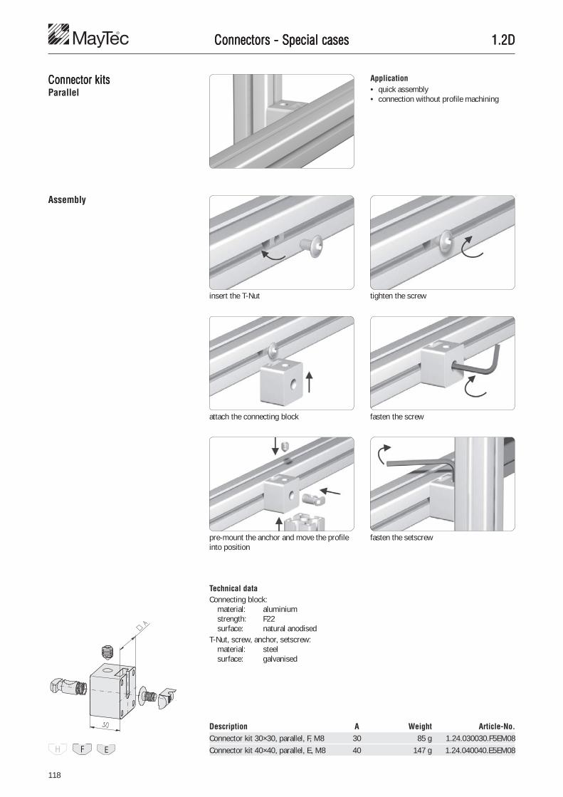
118
1.2D1.2D1.2D1.2D1.2DConnectors - Special casesConnectors - Special casesConnectors - Special casesConnectors - Special casesConnectors - Special cases
Application• quick assembly• connection without profile machining
Assembly
Connector kitsConnector kitsConnector kitsConnector kitsConnector kitsParallel
Description A Weight Article-No.Connector kit 30×30, parallel, F, M8 30 85 g 1.24.030030.F5EM08Connector kit 40×40, parallel, E, M8 40 147 g 1.24.040040.E5EM08
Technical dataConnecting block:
material: aluminiumstrength: F22surface: natural anodised
T-Nut, screw, anchor, setscrew:material: steelsurface: galvanised
fasten the screw
pre-mount the anchor and move the profileinto position
fasten the setscrew
insert the T-Nut tighten the screw
attach the connecting block

119
2
1.2D1.2D1.2D1.2D1.2DConnectors - Special casesConnectors - Special casesConnectors - Special casesConnectors - Special casesConnectors - Special cases
Bayonet type connectorBayonet type connectorBayonet type connectorBayonet type connectorBayonet type connector
insert the cap head screw and the notchingcase into the slot
Pre-assembly of the notching case
Final assembly
positioning with socket pin
tighten the notching case (approx. 45° anti-clockwise turn)
end position of the notching case
pre-mounting of the T-slot nut
join the profiles and tighten the T-slot nut
pre-mounting of the T-slot nut
against clockwise direction
final tightening with socket spanner
Mounting examplefor bayonet type connector with T-slot nut
ApplicationConnection without profile machining.Suitable for the connection of profiles withE-slots to profiles with E- or F-slots.
ApplicationSuitable for the subsequent mounting ofprofiles

120
1.2D1.2D1.2D1.2D1.2DConnectors - Special casesConnectors - Special casesConnectors - Special casesConnectors - Special casesConnectors - Special cases
Description Weight Article-No.Socket pin for notching case E 58.0 g 1.25.WZ1
Description Pcs. Weight Article-No.Bayonet type connector E, with T-Nut (spring ball) E 24.4 g 1.25.E323E
Single parts
Notching case E for bayonet type connector 1 7.5 g 1.25.BECap head screw DIN 912, M6×30 1 8.0 g 0.63.D00912.06030T-Nut for subs. insertion, with spring ball E, M6 1 9.9 g 1.32.3EM6
Description Pcs. Weight Article-No.Bayonet type connector E, with T-slot nut F 16.2 g 1.25.E3410F
Single parts
Notching case E for bayonet type connector 1 7.5 g 1.25.BECap head screw DIN 912, M6×25 1 7.0 g 0.63.D00912.06025T-slot nut F, M6 1 1.7 g 1.34.10FM6
Description Pcs. Weight Article-No.Bayonet type connector E, with T-slot nut E 18.5 g 1.25.E3410E
Single parts
Notching case E for bayonet type connector 1 7.5 g 1.25.BECap head screw DIN 912, M6×30 1 8.0 g 0.63.D00912.06030T-slot nut E, M6 1 3.0 g 1.34.10EM6
with T-slot nut
with T-Nut (spring ball)
Description Pcs. Weight Article-No.Bayonet type connector E, with T-Nut (spring) F 18.8 g 1.25.E324F
Single parts
Notching case E for bayonet type connector 1 7.5 g 1.25.BECap head screw DIN 912, M6×25 1 7.0 g 0.63.D00912.06025T-Nut for subs. insertion, with spring F, M6 1 4.3 g 1.32.4FM6
Description Pcs. Weight Article-No.Bayonet type connector E, with T-Nut (spring) E 25.5 g 1.25.E324E
Single parts
Notching case E for bayonet type connector 1 7.5 g 1.25.BECap head screw DIN 912, M6×30 1 8.0 g 0.63.D00912.06030T-Nut for subs. insertion, with spring E, M6 1 10.0 g 1.32.4EM6
with T-Nut (spring)
Socket pin
Technical data• Notching case, cap head screw,
T-Nut, socket pin:material: steelsurface: galvanised
• T-slot nut:material: GD-Zn
Bayonet type connectorBayonet type connectorBayonet type connectorBayonet type connectorBayonet type connector

121
2
1.2D1.2D1.2D1.2D1.2D
Cross connectorCross connectorCross connectorCross connectorCross connector Application• quick assembly• connection without profile machining
push the lower section of the crossconnector into the slot of the first profile
Assembly
slide the slot of the second profile onto theupper section, position the profiles andtighten the connector
Technical dataLower section, upper section, bolt,screw:
material: steelsurface: galvanised
Description Weight Article-No.Cross connector E3 53.5 g 1.25.41.E3Cross connector E4 55.0 g 1.25.41.E4
Connectors - Special casesConnectors - Special casesConnectors - Special casesConnectors - Special casesConnectors - Special cases

122
1.2D1.2D1.2D1.2D1.2DConnectors - Special casesConnectors - Special casesConnectors - Special casesConnectors - Special casesConnectors - Special cases
Parallel connectorParallel connectorParallel connectorParallel connectorParallel connectorfor subsequent insertion
Application• quick assembly• connection without profile machining
Assembly
Technical datamaterial: steelsurface: galvanised
Description Weight Article-No.Parallel connector, for subsequent insertion, E3/H 21.7 g 1.25.E3H/5Parallel connector, for subsequent insertion, E3/F 24.6 g 1.25.E3F/5Parallel connector, for subsequent insertion, E3/E3 32.6 g 1.25.E3E3/5Parallel connector, for subsequent insertion, E4/F 25.0 g 1.25.E4F/5Parallel connector, for subsequent insertion, E4/E3 33.2 g 1.25.E4E3/5Parallel connector, for subsequent insertion, E4/E4 33.5 g 1.25.E4E4/5
position the setscrew insert the T-Nut
insert and pretension the anchor push on and position the profile
fasten the setscrew

123
2
1.2D1.2D1.2D1.2D1.2D
Clamping connectorClamping connectorClamping connectorClamping connectorClamping connector Application• quick assembly• connection without profile machining
screw the threaded insert M14/M8, 30 intothe core hole � Assembly reference 1.35
Assembly
screw the clamping connector into thethreaded insert
Technical datamaterial: steelsurface: galvanised
Description Weight Article-No.Clamping connector 40E, single sided 34.4 g 1.25.61.40EClamping connector 45E, single sided 31.8 g 1.25.61.45E
Description Weight Article-No.Clamping connector 40E, double sided 43.9 g 1.25.62.40EClamping connector 45E, double sided 42.3 g 1.25.62.45E
slide the connector into the slot of thesecond profile, position the profiles andtighten the connector
Fastening elementThreaded insert M14/M8, 30, 1.35.1140830
Connectors - Special casesConnectors - Special casesConnectors - Special casesConnectors - Special casesConnectors - Special cases

124
1.2E1.2E1.2E1.2E1.2EConnection possibilities for 0-slot profilesConnection possibilities for 0-slot profilesConnection possibilities for 0-slot profilesConnection possibilities for 0-slot profilesConnection possibilities for 0-slot profiles
Connection ofConnection ofConnection ofConnection ofConnection of0-slot profiles0-slot profiles0-slot profiles0-slot profiles0-slot profiles
CommentsConnector � 1.2A
Connector - drill dimensions
without radius covers
with radius covers� 1.43
Cover plugfor connector cross bushings� 1.42
PG 30 PG 40
Drill dimensions without radius covers Drill dimensions without radius covers
Drill dimensions with radius covers Drill dimensions with radius covers
PG 30 PG 40

125
2
1.2E1.2E1.2E1.2E1.2E
�
�
Connection possibilities for 0-slot profilesConnection possibilities for 0-slot profilesConnection possibilities for 0-slot profilesConnection possibilities for 0-slot profilesConnection possibilities for 0-slot profiles
ConnectionConnectionConnectionConnectionConnectionwith standard connectors
Single partsConnector, standard 1.21.3F1 (V)Connector, standard 90° 1.21.3F2 (V)
Single partsConnector, standard 1.21.4E1 (V)Connector, standard 90° 1.21.4E2 (V)
PG 30 PG 40
Mounting variationfor profiles with 1 connector
Assembly� insert connector� turn profile
Fabrication measurements
PG 30 PG 40 PG 45
For fastening of profile 30×30 For fastening of profile 40×40 For fastening of profile 45×45

126
1.2E1.2E1.2E1.2E1.2E
�
�
Connection possibilities for 0-slot profilesConnection possibilities for 0-slot profilesConnection possibilities for 0-slot profilesConnection possibilities for 0-slot profilesConnection possibilities for 0-slot profiles
Mounting variationfor profiles with 1 or more connectors, if theprofile cannot be rotated
Assembly� insert connector� push profile to the top
CommentsPosition of assembly: profiles flush on thetop
for high flexure load
Fabrication measurements
For fastening of profile 30×30 For fastening of profile 40×40 For fastening of profile 45×45
For fastening of profile 30×60 For fastening of profile 40×80 For fastening of profile 45×90
For fastening of profile 60×60 For fastening of profile 80×80 For fastening of profile 90×90
PG 30 PG 40 PG 45

127
2
1.2E1.2E1.2E1.2E1.2E
�
�
Connection possibilities for 0-slot profilesConnection possibilities for 0-slot profilesConnection possibilities for 0-slot profilesConnection possibilities for 0-slot profilesConnection possibilities for 0-slot profiles
Mounting varationfor profiles with 1 or more connectors, if theprofile cannot be rotated
Assembly� insert connector� push profile to the bottom
CommentsPosition of assembly: profiles flush on thetop
for high sliding load
Fabrication measurements
For fastening of profile 30×30 For fastening of profile 40×40 For fastening of profile 45×45
For fastening of profile 30×60 For fastening of profile 40×80 For fastening of profile 45×90
For fastening of profile 60×60 For fastening of profile 80×80 For fastening of profile 90×90
PG 30 PG 40 PG 45

128
1.2E1.2E1.2E1.2E1.2EConnection possibilities for 0-slot profilesConnection possibilities for 0-slot profilesConnection possibilities for 0-slot profilesConnection possibilities for 0-slot profilesConnection possibilities for 0-slot profiles
ConnectionConnectionConnectionConnectionConnectionwith screw-type connector
Single parts• Screw-type connector 1.21.30S1M8/7 (V)• T-Nut for subsequent insertion, with
spring, F 1.32.4FM8 (V)
Single parts• Screw-type connector 1.21.4S1M8/11 (V)• T-Nut for subsequent insertion, with
spring, E 1.32.4EM8 (V)
PG 30 PG 40
Fabrication measurements
PG 30 PG 40 PG 45
For fastening of profile 30×30 For fastening of profile 40×40 For fastening of profile 45×45
For fastening of profile 30×60 For fastening of profile 40×80 For fastening of profile 45×90
For fastening of profile 60×60 For fastening of profile 80×80 For fastening of profile 90×90

129
2
1.2E1.2E1.2E1.2E1.2EConnection possibilities for 0-slot profilesConnection possibilities for 0-slot profilesConnection possibilities for 0-slot profilesConnection possibilities for 0-slot profilesConnection possibilities for 0-slot profiles
ConnectionConnectionConnectionConnectionConnectionwith DIN-Screw
Single parts• Threaded insert M14/M8 1.35.1140815• Cap head screw DIN 6912, M8×20 0.63.D06912.08020• Washer, DIN 433 - 8.4 0.62.D00433.08,4• Cover plug Ø15 1.42.6114.x
PG 30 PG 40 / 45
Fabrication measurements
drill dimensions drill dimensions
PG 30 PG 40 PG 45
For fastening of profile 30×30 For fastening of profile 40×40 For fastening of profile 45×45
For fastening of profile 30×60 For fastening of profile 40×80 For fastening of profile 45×90
For fastening of profile 60×60 For fastening of profile 80×80 For fastening of profile 90×90

130
1.2E1.2E1.2E1.2E1.2EConnection possibilities for profiles 40, roundConnection possibilities for profiles 40, roundConnection possibilities for profiles 40, roundConnection possibilities for profiles 40, roundConnection possibilities for profiles 40, round
Connection ofConnection ofConnection ofConnection ofConnection ofprofiles 40, roundprofiles 40, roundprofiles 40, roundprofiles 40, roundprofiles 40, round
30°
Calculation formulas for polygonsCalculation formulas for polygonsCalculation formulas for polygonsCalculation formulas for polygonsCalculation formulas for polygons
Drill dimensions for profiles 40, round
45°
60° 90°
Profile 40, round 30° (� = 30°) Profile 40, round 45° (� = 45°) Profile 40, round 60° (� = 60°)
t = 22.04 t = 24.57 t = 28.04s = 15.53 s = 22.96 s = 30.00
SW L = × 0.51764 – 31.06 × 0.76537 – 45.92 – 60
R0 L = R0×0.51764 – 31.06 R0×0.76537 – 45.92 R0 – 60
Ra L = (Ra–20)×0.51764 – 31.06 (Ra–20)×0.76537 – 45.92 Ra – 80
SW – 44.08
3.73205�����
SW – 49.14
3.4142����
SW – 56.08
3��
SW R0 =SW – 44.08
3.73205�����
SW – 49.14
3.4142����
SW – 56.08
3��
SW Ra = + 20 + 20 + 20SW – 44.08
3.73205�����
SW – 49.14
3.4142����
SW – 56.08
3��
R0 SW = (R0×2)2 – (R0×0.51764)2 + 44.08 (R0×2)2 – (R0×0.76537)2 + 49.14 (R0×2)2 – R02 + 56.08
Ra SW = ((Ra–20)×2)2 – ((Ra–20)×0.51764)2 + 44.08 ((Ra–20)×2)2 – ((Ra–20)×0.76537)2 + 49.14 ((Ra–20)×2)2 – Ra2 + 56.08
��������
�����������
��������
�����������
know
n
sear
ched
�����
������

131
2
1.2E1.2E1.2E1.2E1.2EConnection possibilities - Special casesConnection possibilities - Special casesConnection possibilities - Special casesConnection possibilities - Special casesConnection possibilities - Special cases
Subsequent mountingSubsequent mountingSubsequent mountingSubsequent mountingSubsequent mountingof profilesof profilesof profilesof profilesof profiles
Step by step instruction for subsequentmounting of profiles with two standardconnections for all profile groups
1. Mill on both ends a slot size of 6×8 mm.
2. Mount connector and fix anchor in frontposition with setscrew.
3. Mount profile.
4. Loosen setscrew.Due to the compressing spring theanchor is pushed into the slot.Turn anchor by 90° with screw driver.Fasten setscrew.
For the subsequent mounting of the profile:

132
1.2E1.2E1.2E1.2E1.2EConnection possibilities - Other profile systemsConnection possibilities - Other profile systemsConnection possibilities - Other profile systemsConnection possibilities - Other profile systemsConnection possibilities - Other profile systems
Connection of MayTConnection of MayTConnection of MayTConnection of MayTConnection of MayTecececececwith other profile systemswith other profile systemswith other profile systemswith other profile systemswith other profile systems
Form H Form H
Form F Form E
anchor dim.
wall thickness holedistance
MayTec profiles can easily be combined withother profile systems.
2. Hole distanceDuring the machining of the cross bore thehole distance has to match the wallthickness of the profile.
hole distance =anchor dim. - wall thickness + 2 mm
With the MayTec Standard-connector twopoints have to be considered:
With the MayTec Screw-type connector andthe T-Nut of the other profile system
1. Anchor head-form and sizeThe MayTec system provides 3 anchor headsizes. If any of the sizes don’t fit into theslots of other profile systems, the anchorhead can be made to fit as required.
Cross bushing
Anchor
T-Nut
MayTec
Other profile
holedistance 10 mm
holedistance 33 mm

133
2
1.2F1.2F1.2F1.2F1.2FStrength values for profile connectionsStrength values for profile connectionsStrength values for profile connectionsStrength values for profile connectionsStrength values for profile connections
with MayTwith MayTwith MayTwith MayTwith MayTec-Connectorsec-Connectorsec-Connectorsec-Connectorsec-Connectors
Torque tightening values forconnector setscrew
20 H M6×8 5.0 Nm 6.0 NmF M8×10 15.0 Nm 20.0 Nm
30 F M10×12 25.0 Nm 30.0 Nm40 E M10×12 30.0 Nm 40.0 Nm45 E M10×12 30.0 Nm 40.0 Nm50 E M10×12 30.0 Nm 40.0 Nm60 E M10×12 30.0 Nm 40.0 Nm
20 H - 1,500 N - M4 4,000 NF 5,000 N 6,000 N 8,000 N M8 8,000 N
30 F 5,000 N 6,000 N 8,000 N M8 8,000 N40 E 10,000 N 12,000 N 12,000 N M8 12,000 N45 E 15,000 N 18,000 N 20,000 N M8 20,000 N50 E 15,000 N 18,000 N 20,000 N M8 20,000 N60 E 15,000 N 18,000 N 20,000 N M8 20,000 N
PG Slot Setscrew Torque valuespecial execution recommended max.
CommentsAll values given havebeen tested with pre-tension of theconnectors andmaximum torque valueand refer to theconnection of twoidentical profiles.
PG Slot max. Tensile strengthConnector T-Nut
Standard Universal Square head
Tension load
Slide load
20 20×20 H 1 1,500 N - 50 Nm20×40 2 3,000 N - 100 Nm 150 Nm40×40 4 6,000 N - 300 Nm20×30 F 1 5,000 N 7,500 N 65 Nm
30 30×30 F 1 5,000 N 7,500 N 100 Nm30×50 1 5,000 N 7,500 N 100 Nm 160 Nm30×60 2 10,000 N 15,000 N 200 Nm 400 Nm30×100, 5F 2 10,000 N 15,000 N 200 Nm 640 Nm30×100, 8F 3 15,000 N 22,500 N 300 Nm 960 Nm30×150, 8F 3 15,000 N 22,500 N 300 Nm 1,500 Nm60×60 angle 3 15,000 N 22,500 N 500 Nm60×60 4 20,000 N 30,000 N 800 Nm30×150 E 2 12,000 N 18,000 N 500 Nm 2,000 Nm
40 40×40 E 1 6,000 N 9,000 N 250 Nm40×60 1 6,000 N 9,000 N 250 Nm 375 Nm40×80 2 12,000 N 18,000 N 500 Nm 1,000 Nm40×120 3 18,000 N 27,000 N 750 Nm 2,250 Nm40×160 4 24,000 N 36,000 N 1,000 Nm 4,000 Nm80×80 angle 3 18,000 N 27,000 N 1,250 Nm80×80, 8E 4 24,000 N 36,000 N 2,000 Nm80×120 6 36,000 N 54,000 N 3,000 Nm 4,500 Nm120×120 8 48,000 N 72,000 N 6,000 Nm80×160 8 48,000 N 72,000 N 4,000 Nm 8,000 Nm
45 45×45 E 1 6,000 N 9,000 N 360 Nm45×60 1 6,000 N 9,000 N 360 Nm 480 Nm45×90 2 12,000 N 18,000 N 720 Nm 1,440 Nm90×90 4 24,000 N 36,000 N 2,880 Nm
50 50×50 E 1 6,000 N 9,000 N 400 Nm50×100, 6E 2 12,000 N 18,000 N 800 Nm 1,600 Nm50×100, 8E 3 18,000 N 27,000 N 1,200 Nm 2,400 Nm50×150 3 18,000 N 27,000 N 1,200 Nm 3,600 Nm100×100 4 24,000 N 36,000 N 3,200 Nm100×200 8 48,000 N 72,000 N 6,400 Nm 12,800 Nm
60 60×60 E 1 6,000 N 9,000 N 480 Nm60×90 2 12,000 N 18,000 N 960 Nm 1,440 Nm
Flexure load
PG Profile Slot Pcs max. Slide strength max. Flexure strength
Connector
Standard, E-connector Standard, Universal, Square headUniversal, (Standard,
Square head Universal)
CommentsThe max. tighteningvalues are only valid forthe MayTec setscrewand can not be reachedby the usual commercialquality standard.
The listed values are validThe listed values are validThe listed values are validThe listed values are validThe listed values are validfor all light and heavyfor all light and heavyfor all light and heavyfor all light and heavyfor all light and heavyprofilesprofilesprofilesprofilesprofiles

134
1.291.291.291.291.29Connection elementsConnection elementsConnection elementsConnection elementsConnection elements
Description Weight Article-No.Retaining plate 13 g 1.29.11140
Retaining platesRetaining platesRetaining platesRetaining platesRetaining plates
Description Weight Article-No.Retaining plate for connector 11 g 1.29.11240
Technical datamaterial: steelsurface: galvanised

135
2
1.291.291.291.291.29Connection elementsConnection elementsConnection elementsConnection elementsConnection elements
Anti-twist devicesAnti-twist devicesAnti-twist devicesAnti-twist devicesAnti-twist devices ApplicationIn the case of high torque forces withconnections of one connector only, twistingcan be prevented by mounting 1 or 2 anti-twist devices.
The nose of the anti-twist device fits into thebasic profile.
Technical datamaterial: steelsurface: galvanisedmax. moment of torque: MA, max
Description G MA, max Weight Article-No.Anti-twist device F M6 10 Nm 7.3 g 1.29.321.FM6
Description G MA, max Weight Article-No.Anti-twist device E M6 10 Nm 14 g 1.29.321.EM6
Fastening elementsF-slot:Setscrew M6×8 1.20.G0608E-slot:Setscrew M6×12 1.20.G0612

136
1.291.291.291.291.29Connection elementsConnection elementsConnection elementsConnection elementsConnection elements
Anti-twist devicesAnti-twist devicesAnti-twist devicesAnti-twist devicesAnti-twist devicesfor subsequent insertion
ApplicationIn the case of high torque forces withconnections of one connector only, twistingcan be prevented by mounting 1 or 2 anti-twist devices.• for subsequent insertion
The nose of the anti-twist device fits into thebasic profile.
Insert front-sided and rotate
Technical datamaterial: steelsurface: galvanisedmax. moment of torque: MA, max
Description G MA, max Weight Article-No.Anti-twist device F M6 for subsequent insertion 10 Nm 7.3 g 1.29.324.FM6
Description G MA, max Weight Article-No.Anti-twist device E M6 for subsequent insertion 10 Nm 14 g 1.29.324.EM6
Fastening elementsF-slot:Setscrew ISO 4026 M6×8 1.20.G0608E-slot:Setscrew ISO 4026 M6×12 1.20.G0612

137
2
1.291.291.291.291.29Connection elementsConnection elementsConnection elementsConnection elementsConnection elements
Clamping leversClamping leversClamping leversClamping leversClamping levers ApplicationAny MayTec connector can be equipped witha clamping lever.For frequent opening and closing
Clamping lever for drill jigs
Technical dataclamping handle: PA-glass-fiber reinf.clamping lever: with ratchet lever handleannular gear: die casted zincthread: steel
Clamping lever for connector
Clamping levers 40for connector
Description G L Weight Article-No.Clamping lever 40 for connector M6 20 17 g 1.29.500620Clamping lever 40 for connector M8 20 21 g 1.29.500820Clamping lever 40 for connector M10 20 24 g 1.29.501020Clamping lever 40 for connector M10 30 29 g 1.29.501030
Description G L Weight Article-No.Clamping lever 65 for connector M6 20 36 g 1.29.650620Clamping lever 65 for connector M8 20 41 g 1.29.650820Clamping lever 65 for connector M8 30 43 g 1.29.650830Clamping lever 65 for connector M10 20 44 g 1.29.651020Clamping lever 65 for connector M10 30 49 g 1.29.651030
Description G L Weight Article-No.Clamping lever 80 for connector M8 20 64 g 1.29.800820Clamping lever 80 for connector M10 20 65 g 1.29.801020Clamping lever 80 for connector M10 30 70 g 1.29.801030
Clamping levers 65for connector
Clamping levers 80for connector

138

139
3
1.3-1.91.3-1.91.3-1.91.3-1.91.3-1.9
T-Boltsfront-sided insertion
� 152
SummarSummarSummarSummarSummary: Accessoriesy: Accessoriesy: Accessoriesy: Accessoriesy: Accessories
Cover profiles� 157
Reducing profiles� 158
Combination profiles� 159
Threaded platesfor subs. insertion
� 143
T-Nuts� 145
Threaded plates� 142
T-Nutsfor subs. insertion
� 146-148
Spring-nutsfront-sided insertion
� 149
Combination profilesfor sliding profiles
� 162
Framing profilesone piece� 164
Sponge rubberround cords� 166-167
Framing profiles� 169-171
Rubber cover-profiles� 172
Cover capsfor profiles� 173-175
Floor levellingscrews� 181
Cover plugs forcross bushings
� 176
Guide profilefor sliding profile
� 163
Radius covers� 178-179
Radiuscompensations
� 180
Cover cap Ø48for hand rail profile
� 175
1.3 Fastening elements
1.4 Installation accessories
Levelling feet� 183
Angular adjusting feet� 189
Base angle� 196
Base foot� 190
Fixed castors� 197
Adjustable tilt-feet� 184-188
Swivel castors� 198
Swivel castorslockable� 198
Angles� 201
Angles Alu� 210
Angles PA� 202
Angles GD-Zn� 203-208
Levelling foot PA 20� 181
Hand adjustable feet� 182
T-slot nuts� 150
Rhomboid T-slot nutswith self-locking
� 151
Threaded inserts� 153-154
Press-fitthreaded inserts
� 155-156
Cover capsfor tubes� 177
Cover capsfor screw bores
� 177
Cover plugs domedfor cross bushings
� 176
Stacking foot� 196
Swivel anglesstraight design
� 211
Swivel angles� 211-212
Cross connectionplates� 212
Base plates� 213-214
Mounting plates� 216
Floor plate� 216
Base feet� 191-195
Connection plates� 217
Threaded platesheavy� 144
Cover profiles� 157
Combination profiles� 160
Wegde profiles� 165
Sealing profile� 168
Floor mounting plate� 215
Locking castors� 199-200
Angles GD-Al� 209

140
1.3-1.91.3-1.91.3-1.91.3-1.91.3-1.9SummarSummarSummarSummarSummary: Accessoriesy: Accessoriesy: Accessoriesy: Accessoriesy: Accessories
1.5 Pneumatic accessories
Pneumaticend plates
� 225-229
Pneumaticconnection plates
� 230
Pneumatic-90°connection sets
� 232-233
Pneumaticextension sets
� 231
Pneumaticaccessories
� 233
1.6 Additional accessories
Roller fastening sets� 286-289
Magnetic lock PA� 269
Bullet catches� 267
Bullet catch PA� 268
Cylinder lockswith security latch
� 272
Flap-lock countersunk� 273
Twin track guide� 285
Rollers� 284-285
Bar locks� 279-282
Mortise deadlocks� 275-278
Cylinder locks� 271
Handlelight
� 234
Handles PA� 235
Grab handle profiles� 238
Hinges� 239, 244
Alu hinges� 251-252
Joints� 255-257
Jointswith clamping lever
� 255-257
Handle PA withmounting thread
� 235
Handle systemround design
� 236
Handle systemoval design
� 237
Grab handlesmade of profiles
� 238
Mounting blocksfor subs. insertion
� 260-261
Mounting clampblocks for subs. ins.
� 262-264
Quick locks� 265-266
Mounting blocksscrew-type
� 258
Lift-off hinges� 240-243
Hinges� 246-250
Handleslight PA� 234
Double hinge� 245
Cylinder locksflush
� 273-274
Latch lock� 283
Alu-C-trackfor suspended doors
� 292
Runnerfor suspended doors
� 293
Stopperfor suspended doors
� 293
Mounting adaptorfor roller� 290
Alu hinges,heavy
� 253-254
Edge roller� 291
Corner piecescubic
� 222-223
Corner piecessegment
� 222-223
Corner piecessegment, 2gang
� 222-223
Corner piece setcubic PA� 220
Corner piece set45° PA� 221
Corner piece setspherical PA
� 221
Mounting blockGD-Zn� 259
Fastening platefor joint 30×100
� 218
Eye-bolt� 219
Corner piecessphere
� 222-223
Lock� 270

141
3
1.3-1.91.3-1.91.3-1.91.3-1.91.3-1.9SummarSummarSummarSummarSummary: Accessoriesy: Accessoriesy: Accessoriesy: Accessoriesy: Accessories
1.7 Electrical accessories
Block forcable binder
� 309
Cable and hoseclamp� 308
Mounting setfor 19" profile
� 311
Safety switches� 312-313
Safety interlocking-mountings� 314-318
Electrical installation trunking� 320-323
Potential equalisation� 306
Ground connections� 307
Installation rings� 310
Sensor brackets� 319
1.8 Panel elements
Corner elements forwire net m. profile
� 328
Panel elements� 331-334
Wire nets, grid� 334-335
Drill jigs� 340, 342
Milling cutters� 341, 343-344
Screw taps� 345-346
Drills� 341, 343-344
Corner element 33 forwire net m. prf. 33×10
� 329
Mounting sockets� 330
1.9 Tools
Button head screws� 338
Electrical installation trunkings� 324-327
Frame guidefor suspended doors
� 293
Sliding blocks� 298
T-Nut sliding blocks� 299
Bottom guidefor suspended doors
� 293
Rubber door stopfor suspended doors
� 293
Slot rollers� 296
Runner for slidingsuspended doors
� 294
Suspended glider� 305
Hanging bracket� 304
Eco-Slides� 300-303
Press in device forknurled cross bushing
� 338
Tx screw driver� 338
Self locking washers� 336-337

142
1.311.311.311.311.31Fastening elementsFastening elementsFastening elementsFastening elementsFastening elements
Threaded platesThreaded platesThreaded platesThreaded platesThreaded plates ApplicationFastening element for screw-typeconnections
Fixed into position with leaf spring
AssemblyInsert from end
Technical datamaterial: steelsurface: galvanisedmax. moment of torque: MA, max
Description G MA, max Weight Article-No.Threaded plate H M3 1.3 Nm 1.5 g 1.31.HM3Threaded plate H M4 2.0 Nm 1.3 g 1.31.HM4Threaded plate H M5 2.0 Nm 1.2 g 1.31.HM5
Description G MA, max Weight Article-No.Threaded plate F M3 1.3 Nm 3.9 g 1.31.FM3Threaded plate F M4 3.0 Nm 3.7 g 1.31.FM4Threaded plate F M5 5.0 Nm 3.6 g 1.31.FM5Threaded plate F M6 7.0 Nm 3.3 g 1.31.FM6
Description G MA, max Weight Article-No.Threaded plate E M3 1.3 Nm 12.0 g 1.31.EM3Threaded plate E M4 3.0 Nm 11.8 g 1.31.EM4Threaded plate E M5 5.0 Nm 11.6 g 1.31.EM5Threaded plate E M6 8.0 Nm 11.3 g 1.31.EM6Threaded plate E M8 15.0 Nm 11.0 g 1.31.EM8

143
3
1.311.311.311.311.31Fastening elementsFastening elementsFastening elementsFastening elementsFastening elements
Threaded platesThreaded platesThreaded platesThreaded platesThreaded platesfor subsequent insertion
ApplicationFastening element for screw-typeconnections
AssemblyInsert frontally and turn 60°
Technical datamaterial: steelsurface: galvanisedmax. moment of torque: MA, max
Description G MA, max Weight Article-No.Threaded plate for subsequent insertion H M3 1.3 Nm 0.90 g 1.31.4HM3Threaded plate for subsequent insertion H M4 2.0 Nm 0.85 g 1.31.4HM4Threaded plate for subsequent insertion H M5 2.0 Nm 0.80 g 1.31.4HM5

144
1.311.311.311.311.31
Threaded platesThreaded platesThreaded platesThreaded platesThreaded platesheavy
ApplicationFastening element for• screw-type connections• hinges, heavy, type 20, 21, 22, 23, 31
Fixed into position with leaf spring
AssemblyInsert from end
Technical datamaterial: steelsurface: galvanisedmax. moment of torque: MA, max
Fastening elementsFastening elementsFastening elementsFastening elementsFastening elements
Description G MA, max Weight Article-No.Threaded plate, heavy E M6 10.0 Nm 17.2 g 1.31.6EM6Threaded plate, heavy E M8 26.0 Nm 16.3 g 1.31.6EM8
Description G MA, max Weight Article-No.Threaded plate, heavy E 2×M6 10.0 Nm 33.8 g 1.31.6E2M6Threaded plate, heavy E 2×M8 26.0 Nm 32.0 g 1.31.6E2M8
Description G MA, max Weight Article-No.Threaded plate, heavy E M6 10.0 Nm 12.4 g 1.31.7EM6
ApplicationFastening element for ST-Connectorwith anchor, screw-type � 1.2DApplication sample � Eco-Slide 1.67
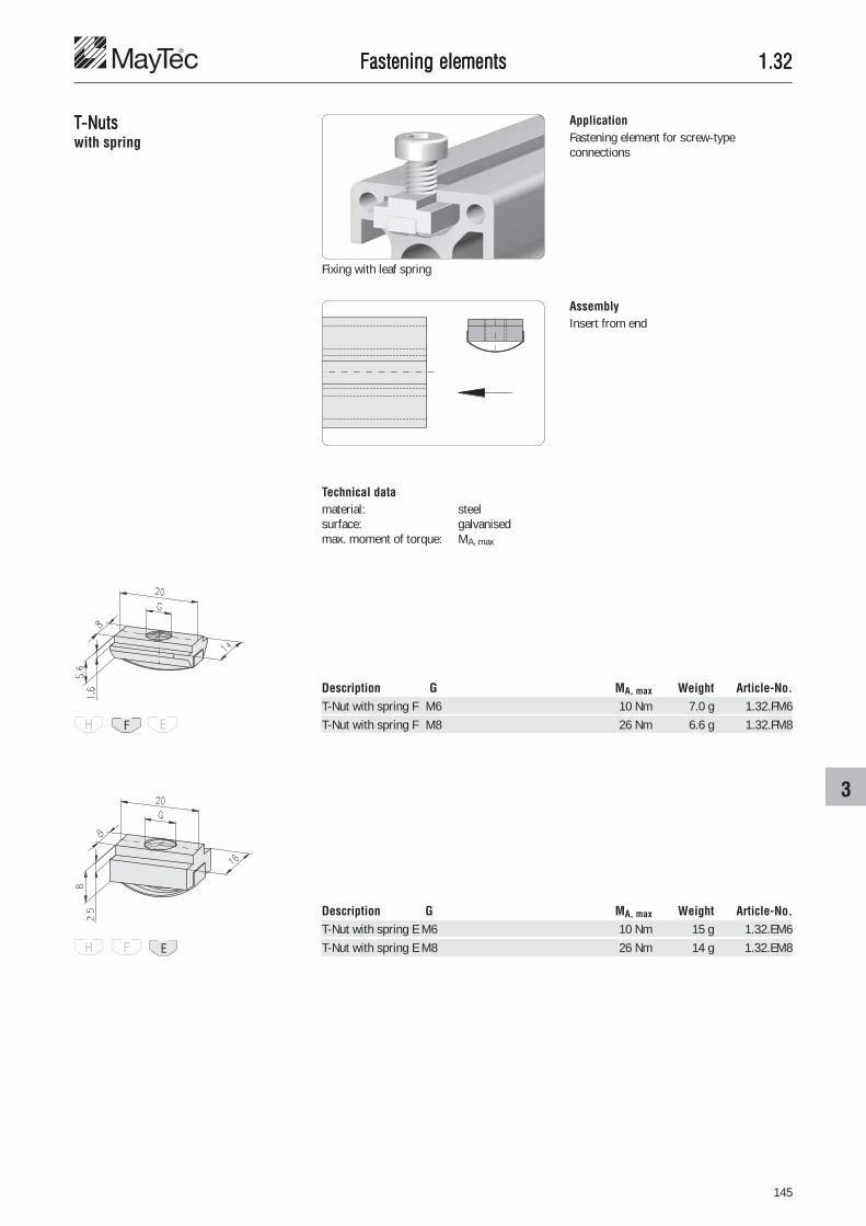
145
3
1.321.321.321.321.32Fastening elementsFastening elementsFastening elementsFastening elementsFastening elements
TTTTT-Nuts-Nuts-Nuts-Nuts-Nutswith spring
ApplicationFastening element for screw-typeconnections
AssemblyInsert from end
Description G MA, max Weight Article-No.T-Nut with spring F M6 10 Nm 7.0 g 1.32.FM6T-Nut with spring F M8 26 Nm 6.6 g 1.32.FM8
Technical datamaterial: steelsurface: galvanisedmax. moment of torque: MA, max
Description G MA, max Weight Article-No.T-Nut with spring E M6 10 Nm 15 g 1.32.EM6T-Nut with spring E M8 26 Nm 14 g 1.32.EM8
Fixing with leaf spring

146
1.321.321.321.321.32Fastening elementsFastening elementsFastening elementsFastening elementsFastening elements
TTTTT-Nuts-Nuts-Nuts-Nuts-Nutsfor subsequent insertion,with spring ball
ApplicationFastening element for screw-typeconnections
Fixing with spring ball
Technical datamaterial: steelsurface: galvanisedmax. moment of torque: MA, max
Description G MA, max Weight Article-No.T-Nut for subs. insertion, w. spring ball E M4 3.0 Nm 10.4 g 1.32.3EM4T-Nut for subs. insertion, w. spring ball E M5 5.0 Nm 10.2 g 1.32.3EM5T-Nut for subs. insertion, w. spring ball E M6 10.0 Nm 9.9 g 1.32.3EM6T-Nut for subs. insertion, w. spring ball E M8 26.0 Nm 9.6 g 1.32.3EM8
AssemblyInsert front-sided and rotate

147
3
1.321.321.321.321.32Fastening elementsFastening elementsFastening elementsFastening elementsFastening elements
TTTTT-Nuts-Nuts-Nuts-Nuts-Nutsfor subsequent insertion,with spring
ApplicationFastening element for screw-typeconnections
Fixing with leaf spring
Insert front-sided and rotate
Description G Design MA, max Weight Article-No.T-Nut for subs. ins., w. spring F M3 steel 1.3 Nm 5.0 g 1.32.4FM3T-Nut for subs. ins., w. spring F M4 steel 3.0 Nm 4.9 g 1.32.4FM4T-Nut for subs. ins., w. spring F M5 steel 5.0 Nm 4.6 g 1.32.4FM5T-Nut for subs. ins., w. spring F M6 steel 10.0 Nm 4.3 g 1.32.4FM6T-Nut for subs. ins., w. spring F M8 steel 10.0 Nm 3.7 g 1.32.4FM8
T-Nut for subs. ins., w. spring F M6 stainless 10.0 Nm 4.3 g 1.32.4FM6VT-Nut for subs. ins., w. spring F M8 stainless 10.0 Nm 3.7 g 1.32.4FM8V
Description G Design MA, max Weight Article-No.T-Nut for subs. ins., w. spring E M3 steel 1.3 Nm 10.0 g 1.32.4EM3T-Nut for subs. ins., w. spring E M4 steel 3.0 Nm 10.0 g 1.32.4EM4T-Nut for subs. ins., w. spring E M5 steel 5.0 Nm 10.0 g 1.32.4EM5T-Nut for subs. ins., w. spring E M6 steel 10.0 Nm 10.0 g 1.32.4EM6T-Nut for subs. ins., w. spring E M8 steel 26.0 Nm 9.0 g 1.32.4EM8
T-Nut for subs. ins., w. spring E M4 stainless 3.0 Nm 10.0 g 1.32.4EM4VT-Nut for subs. ins., w. spring E M5 stainless 5.0 Nm 10.0 g 1.32.4EM5VT-Nut for subs. ins., w. spring E M6 stainless 10.0 Nm 10.0 g 1.32.4EM6VT-Nut for subs. ins., w. spring E M8 stainless 26.0 Nm 9.0 g 1.32.4EM8V
Technical dataDesign steel:• material: steel• surface: galvanisedDesign stainless:• material: stainless steel 1.4305• surface: pickled and passivatedmax. moment of torque: MA, max
Description G MA, max Weight Article-No.T-Nut for subs. ins., w. spring E 2×M8 26.0 Nm 20.3 g 1.32.4E2M8.41
ApplicationFastening element for• screw-type connections• hinges, heavy, type 20, 21, 31
Fixing with leaf spring
Technical datamaterial: steelsurface: galvanisedmax. moment of torque: MA, max

148
1.321.321.321.321.32
ApplicationFastening element for screw-typeconnections
Description G MA, max Weight Article-No.T-Nut for subs. ins., w. spring F 2×M4 3.0 Nm 7.0 g 1.32.4F2M4.25
ApplicationFastening element for mounting angle, quicklock � 265
Fastening without washer Fastening with washer
Description G MA, max Weight Article-No.T-Nut for subs. ins., w. spring E 2×M4 3.0 Nm 12.0 g 1.32.4E2M4.25
Fastening elementsFastening elementsFastening elementsFastening elementsFastening elements
TTTTT-Nuts-Nuts-Nuts-Nuts-Nutsfor subsequent insertion,with spring
Fixing with leaf spring
Technical datamaterial: steelsurface: galvanisedmax. moment of torque: MA, max
AssemblyInsert front-sided and rotate

149
3
1.331.331.331.331.33Fastening elementsFastening elementsFastening elementsFastening elementsFastening elements
Spring-nutsSpring-nutsSpring-nutsSpring-nutsSpring-nutsfront-sided insertion
ApplicationFastening element for screw-typeconnectionsApplicable for small loads such as:• enclosures• electric switches
AssemblyInsert front-sided and turn 90°
Technical datamaterial: steelsurface: galvanisedmax. moment of torque: MA, max
Fixing with compressing spring
Description G MA, max Weight Article-No.Spring-nut F M3 1.3 Nm 1.6 g 1.33.FM3Spring-nut F M4 3.0 Nm 1.5 g 1.33.FM4Spring-nut F M5 5.0 Nm 1.3 g 1.33.FM5Spring-nut F M6 8.0 Nm 1.1 g 1.33.FM6
Description G MA, max Weight Article-No.Spring-nut E M3 1.3 Nm 3.9 g 1.33.EM3Spring-nut E M4 3.0 Nm 3.7 g 1.33.EM4Spring-nut E M5 5.0 Nm 3.4 g 1.33.EM5Spring-nut E M6 10.0 Nm 3.0 g 1.33.EM6

150
1.341.341.341.341.34
TTTTT-slot nuts-slot nuts-slot nuts-slot nuts-slot nuts ApplicationFastening element for screw-typeconnections
Fastening elementsFastening elementsFastening elementsFastening elementsFastening elements
Technical datamaterial: GD-Znsurface: galvanisedmax. moment of torque: MA, max
AssemblyMount the T-slot nut onto the screw andinsert into the slotRotate the screw with T-slot nut 90° insideand then fasten
Description G MA, max Weight Article-No.T-slot nut E M4 3.0 Nm 3.6 g 1.34.10EM4T-slot nut E M5 5.0 Nm 3.2 g 1.34.10EM5T-slot nut E M6 10.0 Nm 3.0 g 1.34.10EM6
Description G MA, max Weight Article-No.T-slot nut F M4 3.0 Nm 2.4 g 1.34.10FM4T-slot nut F M5 5.0 Nm 2.0 g 1.34.10FM5T-slot nut F M6 10.0 Nm 1.7 g 1.34.10FM6

151
3
1.341.341.341.341.34
Rhomboid TRhomboid TRhomboid TRhomboid TRhomboid T-slot nuts-slot nuts-slot nuts-slot nuts-slot nutswith self-locking
ApplicationFor pre-assembly of threads in the profileslot
AssemblyPre-assemble the rhomboid T-slot nut ontothe screw, and insert into the slot
Fastening elementsFastening elementsFastening elementsFastening elementsFastening elements
Technical datamaterial: GD-Znsurface: galvanisedmax. moment of torque: MA, max
Description G MA, max Weight Article-No.Rhomboid T-slot nut E M3 1.3 Nm 6.5 g 1.34.20EM3Rhomboid T-slot nut E M4 3.0 Nm 6.2 g 1.34.20EM4Rhomboid T-slot nut E M5 5.0 Nm 5.9 g 1.34.20EM5Rhomboid T-slot nut E M6 10.0 Nm 5.5 g 1.34.20EM6
By tightening the screw, the rhomboid T-slotnut is turned 90° and jammed inside the slotwith its conical flanks
Even after loosening the screw, therhomboid T-slot nut will remain wedged inplace

152
1.341.341.341.341.34
TTTTT-Bolts-Bolts-Bolts-Bolts-Boltsfront-sided insertion
ApplicationFastening element for screw-typeconnections
Fastening elementsFastening elementsFastening elementsFastening elementsFastening elements
Fixing with compressing spring
AssemblyInsert front-sided and turn 90°
Technical datamaterial: steelsurface: galvanisedmax. moment of torque: MA, max
Description G×L MA, max Weight Article-No.T-Bolt F M6×20 6 Nm 6.0 g 1.34.FM62T-Bolt F M6×30 6 Nm 7.0 g 1.34.FM63T-Bolt F M8×20 15 Nm 8.0 g 1.34.FM82T-Bolt F M8×30 15 Nm 11.2 g 1.34.FM83
Description G×L MA, max Weight Article-No.T-Bolt E M6×20 6 Nm 9.0 g 1.34.EM62T-Bolt E M6×30 6 Nm 10.0 g 1.34.EM63T-Bolt E M8×20 18 Nm 12.0 g 1.34.EM82T-Bolt E M8×30 18 Nm 14.0 g 1.34.EM83T-Bolt E M8×40 18 Nm 18.0 g 1.34.EM84

153
3
1.351.351.351.351.35
Threaded insertsThreaded insertsThreaded insertsThreaded insertsThreaded inserts ApplicationFor mounting on front end
Fastening elementsFastening elementsFastening elementsFastening elementsFastening elements
Description G Weight Article-No.Threaded insert M12/M4 8.6 g 1.35.11204Threaded insert M12/M5 8.0 g 1.35.11205Threaded insert M12/M6 7.3 g 1.35.11206Threaded insert M12/M8 5.5 g 1.35.11208
Description G Weight Article-No.Threaded insert M8/M4 1.0 g 1.35.10804Threaded insert M8/M5 0.9 g 1.35.10805
Technical datamaterial: steelsurface: galvanised
Commentsfor core hole Ø6
ApplicationFor mounting on front end
Technical datamaterial: steelsurface: galvanised
Commentsfor outer chambers PG 50, heavy

154
1.351.351.351.351.35
1)
1)
1)
Threaded insertsThreaded insertsThreaded insertsThreaded insertsThreaded inserts ApplicationFor mounting on front end and fastening ofany profile with core hole Ø12
Fastening elementsFastening elementsFastening elementsFastening elementsFastening elements
ApplicationFor mounting on front end and fastening ofprofiles PG 45 heavy, PG 50 and PG 60
Technical datamaterial: steelsurface: galvanised
Description D/G L Weight Article-No.Threaded insert M14/M6 15 11 g 1.35.1140615Threaded insert M14/M6 30 22 g 1.35.1140630Threaded insert M14/M8 15 9 g 1.35.1140815Threaded insert M14/M8 30 18 g 1.35.1140830Threaded insert M14/M10 15 6 g 1.35.1141015Threaded insert M14/M10 30 12 g 1.35.1141030
Threaded insert M16/M12 15 8 g 1.35.1161215Threaded insert M16/M12 30 16 g 1.35.1161230
Assembly preparation forthreaded insert M14/Mxx• Tap M14 thread in core hole Ø12 mm
Assembly preparation forthreaded insert M16/M12• Drill Ø12 mm core hole to 14 mm• Tap M16 thread in core hole Ø14 mm

155
3
1.351.351.351.351.35
Press-fit threaded insertsPress-fit threaded insertsPress-fit threaded insertsPress-fit threaded insertsPress-fit threaded inserts ApplicationFor mounting on front end and fastening ofany profile with core hole Ø12
Fastening elementsFastening elementsFastening elementsFastening elementsFastening elements
ApplicationFor screw connections across the profile forcross section of20 mm / 30 mm / 40 mm / 45 mm / 50 mm
Technical datamaterial: steelsurface: galvanised
Description G L l Weight Article-No.Press-fit threaded insert Ø12/M8 22.5 19.5 15 g 1.35.608195Press-fit threaded insert Ø12/M8 32.5 29.5 20 g 1.35.608295Press-fit threaded insert Ø12/M8 42.5 39.5 26 g 1.35.608395Press-fit threaded insert Ø12/M8 47.5 44.5 28 g 1.35.608445Press-fit threaded insert Ø12/M8 52.5 49.5 31 g 1.35.608495Press-fit threaded insert Ø12/M10 22.5 19.5 11 g 1.35.610195Press-fit threaded insert Ø12/M10 32.5 29.5 15 g 1.35.610295Press-fit threaded insert Ø12/M10 42.5 39.5 18 g 1.35.610395Press-fit threaded insert Ø12/M10 47.5 43.5 20 g 1.35.610445Press-fit threaded insert Ø12/M10 52.5 49.5 22 g 1.35.610495
Description G L l Weight Article-No.Press-fit threaded insert Ø16/M14 32.5 29.5 25 g 1.35.614295Press-fit threaded insert Ø16/M14 42.5 39.5 30 g 1.35.614395Press-fit threaded insert Ø16/M14 47.5 44.5 32 g 1.35.614445Press-fit threaded insert Ø16/M14 52.5 49.5 35 g 1.35.614495
ApplicationFor screw connections across the profile forcross section of30 mm / 40 mm / 45 mm / 50 mm
Technical datamaterial: steelsurface: galvanised
borehole-Ø 12+0.1
borehole-Ø 16+0.1

156
1.351.351.351.351.35
Press-fit threaded insertsPress-fit threaded insertsPress-fit threaded insertsPress-fit threaded insertsPress-fit threaded insertsw/o collar
ApplicationFor mounting on front end and fastening ofany profile with core hole Ø12
Fastening elementsFastening elementsFastening elementsFastening elementsFastening elements
Technical datamaterial: steelsurface: galvanised
Description G Weight Article-No.Press-fit threaded insert, w/o collar Ø12/M6 19 g 1.35.606300Press-fit threaded insert, w/o collar Ø12/M8 17 g 1.35.608300

157
4
1.411.411.411.411.41
Cover profilesCover profilesCover profilesCover profilesCover profiles ApplicationCover profile with 1.2 mm jutout for theprotection of the profile slots
Technical databar length: 2.5 mmaterial: PVC rigid• oil and water resistant• anti-electrostatic• lead- and cadmium free
Installation accessoriesInstallation accessoriesInstallation accessoriesInstallation accessoriesInstallation accessories
Description Colour similar to RAL Weight Article-No.Cover profile 10, PVC, F/E, grey 7035 85 g/bar 1.41.11.1Cover profile 10, PVC, F/E, black 9011 85 g/bar 1.41.11.2Cover profile 10, PVC, F/E, yellow 1023 85 g/bar 1.41.11.1023
Description Weight Article-No.Cover profile 10, Alu, F/E 67.5 g/bar 1.41.121
Technical databar length: 2.5 mmaterial: aluminiumsurface: natural anodised
ApplicationCover profile for the protection of the profileslotsDangerous spots can be marked with yellowcover profiles
Description Colour similar to RAL bar Weight Article-No.Cover profile 34, PVC, E, grey 7035 2.5 m 170 g/bar 1.41.15E34.1Cover profile 34, PVC, E, black 9011 2.5 m 170 g/bar 1.41.15E34.2Cover profile 34, PVC, E, blue 5017 2.5 m 170 g/bar 1.41.15E34.5017Cover profile 34, PVC, E, yellow 1003 3.0 m 204 g/bar 1.41.15E34.1003Cover profile 34, PVC, E, orange 2004 3.0 m 204 g/bar 1.41.15E34.2004
Technical databar length: 2.5 m (grey, black, blue)
3.0 m (yellow, orange)material: PVC rigid• oil and water resistant

158
1.411.411.411.411.41
Reducing profiles PVCReducing profiles PVCReducing profiles PVCReducing profiles PVCReducing profiles PVC ApplicationTo reduce the slot size from 8 mm to 6 mm
Technical databar length: 2.5 mmaterial: PVC rigid• oil and water resistant• anti-electrostatic• lead- and cadmium free
Installation accessoriesInstallation accessoriesInstallation accessoriesInstallation accessoriesInstallation accessories
Description Colour similar to RAL Weight Article-No.Reducing profile PVC, F/E, 8/6 grey 7035 85 g/bar 1.41.21.1Reducing profile PVC, F/E, 8/6 black 9011 85 g/bar 1.41.21.2

159
4
1.411.411.411.411.41
Combination profiles PVCCombination profiles PVCCombination profiles PVCCombination profiles PVCCombination profiles PVC ApplicationCombination profiles for use as reduction orcover profiles
Technical databar length: 2.5 mmaterial: PVC rigid• oil and water resistant
Installation accessoriesInstallation accessoriesInstallation accessoriesInstallation accessoriesInstallation accessories
Description B Colour similar to RAL Weight Article-No.Combination profile PVC, H 2 grey 7035 37.5 g/bar 1.41.H02.1Combination profile PVC, H 2 black 9011 37.5 g/bar 1.41.H02.2Combination profile PVC, H 2 red 3000 37.5 g/bar 1.41.H02.3000Combination profile PVC, H 2 blue 5002 37.5 g/bar 1.41.H02.5002Combination profile PVC, H 2 green 6024 37.5 g/bar 1.41.H02.6024Combination profile PVC, H 4 grey 7035 35.0 g/bar 1.41.H04.1Combination profile PVC, H 4 black 9011 35.0 g/bar 1.41.H04.2
Use as reduction profile
Use as slot-cover profile
Colours: greyblackredbluegreen

160
1.411.411.411.411.41
Combination profilesCombination profilesCombination profilesCombination profilesCombination profiles
Installation accessoriesInstallation accessoriesInstallation accessoriesInstallation accessoriesInstallation accessories
ApplicationCombination profiles for use as reduction orcover profiles
Technical databar length: 2.5 mmaterial: PP• oil and water resistant
Description D Colour similar to RAL Weight Article-No.Combination profile F 1 - 4.5 grey 7035 31 g/bar 1.41.F14.1Combination profile F 1 - 4.5 black 9011 31 g/bar 1.41.F14.2
Use as reduction profile
Use as slot-cover profile
Description D Colour similar to RAL Weight Article-No.Combination profile F 4.5 - 6 grey 7035 28 g/bar 1.41.F46.1Combination profile F 4.5 - 6 black 9011 28 g/bar 1.41.F46.2Combination profile F 4.5 - 6 red 3000 28 g/bar 1.41.F46.3000Combination profile F 4.5 - 6 blue 5002 28 g/bar 1.41.F46.5002Combination profile F 4.5 - 6 green 6024 28 g/bar 1.41.F46.6024
Description D Colour similar to RAL Weight Article-No.Combination profile E 1 - 4.5 grey 7035 47 g/bar 1.41.E314.1Combination profile E 1 - 4.5 black 9011 47 g/bar 1.41.E314.2
Description D Colour similar to RAL Weight Article-No.Combination profile E 4.5 - 6 grey 7035 42 g/bar 1.41.E346.1Combination profile E 4.5 - 6 black 9011 42 g/bar 1.41.E346.2Combination profile E 4.5 - 6 orange 2004 42 g/bar 1.41.E346.2004Combination profile E 4.5 - 6 red 3000 42 g/bar 1.41.E346.3000Combination profile E 4.5 - 6 blue 5002 42 g/bar 1.41.E346.5002Combination profile E 4.5 - 6 green 6024 42 g/bar 1.41.E346.6024
Colours: greyblackorangeredbluegreen

161
4
1.411.411.411.411.41
H = A - 6 H = A - 18 H = A - 30 H = A - 17 H = A - 19H1 = A - 58 H1 = A - 70 H1 = A - 82 H1 = A - 69 H1 = A - 71
H = A - 6 H = A - 18 H = A - 30 H = A - 9 H = A - 19H1 = A - 44 H1 = A - 56 H1 = A - 45
H = A - 8 H = A - 19 H = A - 31 H = A - 9 H = A - 19H1 = A - 45 H1 = A - 57 H1 = A - 45
30×14 30×26 30×26 50×14 50×14
30×14 30×14 30×26 50×14 50×14
Sliding doorsSliding doorsSliding doorsSliding doorsSliding doorsconstruction types
Installation accessoriesInstallation accessoriesInstallation accessoriesInstallation accessoriesInstallation accessories
Fixed Removable
Panelelement6 mm
Panelelement8 mm
Panelelement1 - 14 mm
Profile above
Profile below
Type of mounting Fixed Removable Fixed Removable
Profile Sliding profile 30 mm Sliding profile 50 mm

162
1.411.411.411.411.41
Combination profiles PVCCombination profiles PVCCombination profiles PVCCombination profiles PVCCombination profiles PVC
Installation accessoriesInstallation accessoriesInstallation accessoriesInstallation accessoriesInstallation accessories
ApplicationCombination profiles for sliding profilesalternatively suitable as:• reducing profile• cover profile• Inserted plate (only combination
profile 1.41.330)
Inserted plate for sliding profile 30×26:combination profile 1.41.330
Inserted plate for sliding profile 50×14:for sliding profile 1.41.11.1, 1.41.11.2
Description B Weight Article-No.Combination profile PVC for 30×14 6.2 115 g/bar 1.41.330
Description B Weight Article-No.Combination profile PVC for 50×14 6.5 222.5 g/bar 1.41.350Combination profile PVC for 50×14 9.0 205.0 g/bar 1.41.351
Technical databar length: 2.5 mmaterial: PVC rigid
oil and water resistantcolour: grey

163
4
1.411.411.411.411.41
Guide profile PVCGuide profile PVCGuide profile PVCGuide profile PVCGuide profile PVC
Installation accessoriesInstallation accessoriesInstallation accessoriesInstallation accessoriesInstallation accessories
ApplicationThe guide profile is necessary• For demountable sliding doors• For the use of panel elements of each
plate thickness from 1 mm to 14 mm
Minimum height for lifting of the panelelements
Drill dimensions
Use in sliding profile 30×26
Use in sliding profile 50×14 withcombination profile
Description Weight Article-No.Guide profile PVC for sliding profile 375 g/bar 1.41.360
Technical databar length: 2.5 mmaterial: PVC rigid
oil and water resistantcolour: grey

164
1.411.411.411.411.41
Framing profilesFraming profilesFraming profilesFraming profilesFraming profilesone piece
Installation accessoriesInstallation accessoriesInstallation accessoriesInstallation accessoriesInstallation accessories
ApplicationThe one piece framing profile for mountingpanels of different thicknessThe elastic lips provide a good seal
One sided application for profiles with F-and E-slots and panels 5 - 6 mm thick
One sided application for profiles with H-slots and panels 3 - 4 mm thick
Description Colour Weight Article-No.Framing profile one piece F grey ring 2,200 g/ring 1.41.5F0.1.60Framing profile one piece F grey cut to length 37 g/m 1.41.5F0.1-A00A00/...Framing profile one piece F black ring 2,200 g/ring 1.41.5F0.2.60Framing profile one piece F black cut to length 37 g/m 1.41.5F0.2-A00A00/...
/... = length in mm
Description Colour Weight Article-No.Framing profile one piece E grey ring 3,120 g/ring 1.41.5E0.1.60Framing profile one piece E grey cut to length 52 g/m 1.41.5E0.1-A00A00/...Framing profile one piece E black ring 3,120 g/ring 1.41.5E0.2.60Framing profile one piece E black cut to length 52 g/m 1.41.5E0.2-A00A00/...
/... = length in mm
Two sided application for profiles with F-and E-slots and panels 1 - 4 mm thick
Technical datalength of ring: 60 mmaterial: NBR - 60 Shore A
• compatible with acrylicglass
• oil and water resistant
Coloursgrey: similar to RAL 7035black: similar to RAL 9011

165
4
1.411.411.411.411.41
WWWWWedge predge predge predge predge profilesofilesofilesofilesofiles ApplicationWedge profiles for sealing or fixing of panelelements with a thickness of 4 mm
Technical datalength of ring: 100 mmaterial: Santoprene• free of silicon• compatible with acrylic glass
Description Colour Weight Article-No.Wedge profile E3 grey ring 5.0 kg/ring 1.41.51E3.1.99Wedge profile E3 grey cut to length 50 g/m 1.41.51E3.1-A00A00/...
/... = length in mm
E3-slot
Length of wedge profile =frame - clear opening + 2 mm
Installation accessoriesInstallation accessoriesInstallation accessoriesInstallation accessoriesInstallation accessories

166
1.411.411.411.411.41
Sponge rubber round cordsSponge rubber round cordsSponge rubber round cordsSponge rubber round cordsSponge rubber round cords
Installation accessoriesInstallation accessoriesInstallation accessoriesInstallation accessoriesInstallation accessories
ApplicationSponge rubber round cords for sealing
Profile with panel element
2 profiles with slots1 profile with slot-cover profile
1 profile with slot1 profile closed
H-slot 8 mm
F-slot 12 mm
E-slot 18 mm
Profile slot Sponge rubber diameter
Sponge rubber round cord diameter-determination

167
4
1.411.411.411.411.41
Sponge rubber round cordsSponge rubber round cordsSponge rubber round cordsSponge rubber round cordsSponge rubber round cords
Installation accessoriesInstallation accessoriesInstallation accessoriesInstallation accessoriesInstallation accessories
ApplicationFor compensation of slot width on in-between sizes of cover panels
Enclosures with panel materials
Description D Weight Article-No.Sponge rubber round cords Ø6 ring 1.1 kg/ring 1.41.606.99Sponge rubber round cords Ø6 cut to length 11 g/m 1.41.606-A00A00/...Sponge rubber round cords Ø8 ring 1.9 kg/ring 1.41.608.99Sponge rubber round cords Ø8 cut to length 19 g/m 1.41.608-A00A00/...Sponge rubber round cords Ø10 ring 3.2 kg/ring 1.41.610.99Sponge rubber round cords Ø10 cut to length 32 g/m 1.41.610-A00A00/...Sponge rubber round cords Ø12 ring 4.6 kg/ring 1.41.612.99Sponge rubber round cords Ø12 cut to length 46 g/m 1.41.612-A00A00/...Sponge rubber round cords Ø18 ring 10.0 kg/ring 1.41.618.99Sponge rubber round cords Ø18 cut to length 100 g/m 1.41.618-A00A00/...
/... = length in mm
Enclosures with wire screens
H-slot 1 - 3 mm 6 mm
F-slot 1 - 2 mm 10 mm3 mm 8 mm
4 - 5 mm 6 mm
E-slot 1 - 3 mm 10 mm3 - 4 mm 2×8 mm
5 mm 2×6 mm
Profile slot Plate thickness Sponge rubber diameter
Sponge rubber round cord diameter-determination
Technical datalength of ring: 100 mmaterial: EPDMcolour: grey

168
1.411.411.411.411.41
Sealing profileSealing profileSealing profileSealing profileSealing profile
Installation accessoriesInstallation accessoriesInstallation accessoriesInstallation accessoriesInstallation accessories
ApplicationFor sealing of doors and windows and fordoor stops
Technical datalength of ring: 40 mmaterial: EPDM, 60° ± 5° Shore A• free of silicon• compatible with acrylic glass
Description Colour Weight Article-No.Sealing profile F black ring 5.12 kg/ring 1.41.6510F.2.40Sealing profile F black cut to length 128 g/m 1.41.6510F.2-A00A00/...
/... = length in mm

169
4
1.411.411.411.411.41
Framing profilesFraming profilesFraming profilesFraming profilesFraming profiles
Installation accessoriesInstallation accessoriesInstallation accessoriesInstallation accessoriesInstallation accessories
ApplicationThe framing profile allows the installation ofpanels in closed frames
Description Colour Weight Article-No.Framing profile F/E grey bar 1.1 kg/bar 1.41.710.1.60Framing profile F/E grey cut to length 181 g/m 1.41.710.1-A00A00/...Framing profile F/E black bar 1.1 kg/bar 1.41.710.2.60Framing profile F/E black cut to length 181 g/m 1.41.710.2-A00A00/...
/... = length in mm
Maximum loading of framing profile:Fmax = 200 N/mFor maximum loading of element be awareof the stability of used framing profile
Assembly1. Insert base profile in profile slot2. Put panel element in position3. Push clamping strip in position
CommentsThe clamping strip is badged by a notch as adistinctive mark to the base profile
Technical databar length: 6 mmaterial: • base body: PVC rigid, 98° Shore A
• lip: PVC soft, TPE 60° ± 5° Shore A, compatible with acrylic glasstemperature range: -20°C to +80°C
panel element
notchbase profile
clampingstrip
CommentsSuitable for panel elements from 1 to 10 mmthickness
Coloursgrey: similar to RAL 7035black: similar to RAL 9011

170
1.411.411.411.411.41Installation accessoriesInstallation accessoriesInstallation accessoriesInstallation accessoriesInstallation accessories
CommentsSuitable for panel elements from 1 to 7 mmthickness
Description Colour Weight Article-No.Framing profile F/E, 1-7 mm grey bar 960 g/bar 1.41.720107.1.60Framing profile F/E, 1-7 mm grey cut to length 160 g/m 1.41.720107.1-A00A00/...Framing profile F/E, 1-7 mm black bar 960 g/bar 1.41.720107.2.60Framing profile F/E, 1-7 mm black cut to length 160 g/m 1.41.720107.2-A00A00/...
/... = length in mm
Coloursgrey: similar to RAL 7035black: similar to RAL 9011

171
4
1.411.411.411.411.41
Framing profilesFraming profilesFraming profilesFraming profilesFraming profiles ApplicationThe framing profile allows the installation ofpanels in closed frames
Description Colour Weight Article-No.Framing profile E grey bar 1.1 kg/bar 1.41.71E0110.1.60Framing profile E grey cut to length 181 g/m 1.41.71E0110.1-A00A00/...Framing profile E black bar 1.1 kg/bar 1.41.71E0110.2.60Framing profile E black cut to length 181 g/m 1.41.71E0110.2-A00A00/...
/... = length in mm
Maximum loading of framing profile:Fmax = 200 N/mFor maximum loading of element be awareof the stability of used framing profile
Assembly1. Insert base profile in profile slot2. Put panel element in position3. Push clamping strip in position
CommentsThe clamping strip is badged by a bulge as adistinctive mark to the base profile
Technical databar length: 6 mmaterial: • base body: PVC rigid, 98° Shore A
• lip: PVC soft, TPE 60° ± 5° Shore A, compatible with acrylic glasstemperature range: -20°C to +80°C
panel element
bulgebase profile
clampingstrip
CommentsSuitable for panel elements from 1 to 10 mmthickness
Coloursgrey: similar to RAL 7035black: similar to RAL 9011

172
1.411.411.411.411.41
Rubber coverRubber coverRubber coverRubber coverRubber cover-pr-pr-pr-pr-profilesofilesofilesofilesofiles
Installation accessoriesInstallation accessoriesInstallation accessoriesInstallation accessoriesInstallation accessories
ApplicationRubber cover-profiles for profile protectionSuitable for:• door stop• slide prevention on steps• protection against damage• handrails• pads
Technical datalength of ring: 20 mmaterial: NBR, hardness 80 Shore A
oil and water resistantcolour: black
Description Weight Article-No.Rubber cover-profile E4, black ring 6.4 kg/ring 1.41.8E50.20Rubber cover-profile E4, black cut to length 320 g/m 1.41.8E50-A00A00/...
/... = length in mm
Description Weight Article-No.Rubber cover-profile F, black ring 2.4 kg/ring 1.41.8F30.20Rubber cover-profile F, black cut to length 120 g/m 1.41.8F30-A00A00/...
/... = length in mm
Description Weight Article-No.Rubber cover-profile E3, black ring 4.4 kg/ring 1.41.8E40.20Rubber cover-profile E3, black cut to length 220 g/m 1.41.8E40-A00A00/...
/... = length in mm

173
4
1.421.421.421.421.42
Cover capsCover capsCover capsCover capsCover caps
Installation accessoriesInstallation accessoriesInstallation accessoriesInstallation accessoriesInstallation accessories
ApplicationCover caps prevent dirt from entering andavoid lacerations.
Technical datamaterial: PA-GFtemperature range: -20°C to +85°C
CommentsBefore mounting debur core hole
Description Colour Weight Article-No.Cover cap 16×80, E grey 7.1 g 1.42.09016080.1Cover cap 16×80, E black 7.1 g 1.42.09016080.2only for E-Slot
Description Colour Weight Article-No.Cover cap 16×40, E black 3.9 g 1.42.09016040.2only for E-Slot
Description Colour Weight Article-No.Cover cap 20×10 black 2 g 1.42.20201.2
Description Colour Weight Article-No.Cover cap 20×20 grey 3 g 1.42.10200.1Cover cap 20×20 black 3 g 1.42.10200.2
Soft
Description Colour Weight Article-No.Cover cap 20×20 grey 3 g 1.42.10202.1Cover cap 20×20 black 3 g 1.42.10202.2
Square
Rectangle
Description Colour Weight Article-No.Cover cap 20×40 grey 6 g 1.42.10204.1Cover cap 20×40 black 6 g 1.42.10204.2
Description Colour Weight Article-No.Cover cap 40×40 black 6 g 1.42.10404.2
Square
Rectanglefor profiles without core hole
for profiles with core hole-Ø6

174
1.421.421.421.421.42
1)
1)
Installation accessoriesInstallation accessoriesInstallation accessoriesInstallation accessoriesInstallation accessories
Description A W h L Colour Weight Article-No.Cover cap 40, round 30° 4 14 black 6 g 1.42.2040R30.2Cover cap 40, round 45° 6 14 black 8 g 1.42.2040R45.2Cover cap 40, round 60° 6 14 black 12 g 1.42.2040R60.2Cover cap 40, round 90° 6 14 black 16 g 1.42.2040R90.2
Description A×B L Colour Weight Article-No.Cover cap 30×30 7 grey 5 g 1.42.20300.1Cover cap 30×30 7 black 5 g 1.42.20300.2Cover cap 40×40 7 grey 8 g 1.42.20400.1Cover cap 40×40 7 black 8 g 1.42.20400.2Cover cap 45×45 14 black 10 g 1.42.2045000.2Cover cap 50×50 7 grey 12 g 1.42.20500.1Cover cap 50×50 7 black 12 g 1.42.20500.2
Description A×B L Colour Weight Article-No.Cover cap 30×30 14 grey 6 g 1.42.20303.1Cover cap 30×30 14 black 6 g 1.42.20303.2Cover cap 40×40 14 grey 10 g 1.42.20404.1Cover cap 40×40 14 black 10 g 1.42.20404.2Cover cap 45×45 14 black 12 g 1.42.2045045.2Cover cap 50×50 7 grey 15 g 1.42.20505.1Cover cap 50×50 7 black 15 g 1.42.20505.2Cover cap 60×60 14 black 18 g 1.42.2060060.2
Soft
Round
Square
note "h" !
Description A×B L Colour Weight Article-No.Cover cap 30×60 7 grey 8 g 1.42.20306.1Cover cap 30×60 7 black 8 g 1.42.20306.2Cover cap 30×100 7 black 20 g 1.42.20310.2Cover cap 30×150 7 black 27 g 1.42.20315.2Cover cap 40×80 7 grey 18 g 1.42.20408.1Cover cap 40×80 7 black 18 g 1.42.20408.2Cover cap 45×90 14 black 20.5 g 1.42.2045090.2Cover cap 50×100 7 grey 26 g 1.42.20510.1Cover cap 50×100 7 black 26 g 1.42.20510.2Cover cap 50×150 7 black 40 g 1.42.20515.2Cover cap 60×90 14 black 25.9 g 1.42.2060090.2only for E-Slot
Description A×B L Colour Weight Article-No.Cover cap 20×30 7 black 4 g 1.42.20203.2Cover cap 30×50 7 grey 8 g 1.42.20305.1Cover cap 30×50 7 black 8 g 1.42.20305.2Cover cap 45×60 14 black 12.1 g 1.42.2045060.2
Rectangle
Description A×B L Colour Weight Article-No.Cover cap 60×80 14 black 21.4 g 1.42.2060080.2
for profiles with core hole-Ø12
!

175
4
1.421.421.421.421.42Installation accessoriesInstallation accessoriesInstallation accessoriesInstallation accessoriesInstallation accessories
Description A×B L Colour Weight Article-No.Cover cap 80×80 7 black 34 g 1.42.20808.2Cover cap 90×90 14 black 42 g 1.42.2090090.2Cover cap 100×100 7 black 52 g 1.42.21010.2
Description L Colour Weight Article-No.Cover cap Ø48 for hand rail profile 14 grey 1.8 g 1.42.2048R00.1Cover cap Ø48 for hand rail profile 14 black 1.8 g 1.42.2048R00.2
Square
Ø48 for hand rail profile Technical datamaterial: PA-GF
Description A×B L Colour Weight Article-No.Cover cap 30×60 for tube profile 14.5 black 10.2 g 1.42.217.030060.2Cover cap 30×100 for tube profile 14.5 black 17.7 g 1.42.217.030100.2
for tube profile

176
1.421.421.421.421.42
Cover plugs domedCover plugs domedCover plugs domedCover plugs domedCover plugs domed
Installation accessoriesInstallation accessoriesInstallation accessoriesInstallation accessoriesInstallation accessories
ApplicationThe cover plug allows the closing of theconnector cross bushing bore
Technical datamaterial: PE
Description Colour L d Weight Article-No.Cover plug 20 domed grey 3.5 Ø4.3 0.2 g 1.42.5120.1Cover plug 20 domed black 3.5 Ø4.3 0.2 g 1.42.5120.2Cover plug 30 domed grey 6.0 Ø5.3 0.3 g 1.42.5130.1Cover plug 30 domed black 6.0 Ø5.3 0.3 g 1.42.5130.2Cover plug 40 domed grey 11.0 Ø5.3 0.4 g 1.42.5140.1Cover plug 40 domed black 11.0 Ø5.3 0.4 g 1.42.5140.2Cover plug 45 domed grey 12.5 Ø5.3 0.4 g 1.42.5145.1Cover plug 45 domed black 12.5 Ø5.3 0.4 g 1.42.5145.2Cover plug 50 domed grey 15.0 Ø5.3 0.5 g 1.42.5150.1Cover plug 50 domed black 15.0 Ø5.3 0.5 g 1.42.5150.2Cover plug 60 domed grey 20.0 Ø5.3 0.7 g 1.42.5160.1Cover plug 60 domed black 20.0 Ø5.3 0.7 g 1.42.5160.2
Cover plugsCover plugsCover plugsCover plugsCover plugs
ApplicationThe cover plug allows the closing of theconnector cross bushing bore
Technical datamaterial: PE
Description Colour L d Weight Article-No.Cover plug 20 grey 3.5 Ø4.3 2 g 1.42.502.1Cover plug 20 black 3.5 Ø4.3 2 g 1.42.502.2Cover plug 30 grey 6.0 Ø5.3 3 g 1.42.503.1Cover plug 30 black 6.0 Ø5.3 3 g 1.42.503.2Cover plug 40 grey 11.0 Ø5.3 4 g 1.42.504.1Cover plug 40 black 11.0 Ø5.3 4 g 1.42.504.2Cover plug 50 grey 16.0 Ø5.3 5 g 1.42.505.1Cover plug 50 black 16.0 Ø5.3 5 g 1.42.505.2
Cover plug in combination with cover profile

177
4
1.421.421.421.421.42
Cover caps for tubesCover caps for tubesCover caps for tubesCover caps for tubesCover caps for tubes
Installation accessoriesInstallation accessoriesInstallation accessoriesInstallation accessoriesInstallation accessories
ApplicationThe cover cap allows the closing of thealuminium tube(inner tube Ø = d)
Technical datamaterial: PE
Description D Colour d Weight Article-No.Tube cover cap Ø20 grey Ø16 1.8 g 1.42.6020.1Tube cover cap Ø20 black Ø16 1.8 g 1.42.6020.2Tube cover cap Ø30 grey Ø24 3.4 g 1.42.6030.1Tube cover cap Ø30 black Ø24 3.4 g 1.42.6030.2Tube cover cap Ø40 grey Ø32 5.3 g 1.42.6040.1Tube cover cap Ø40 black Ø32 5.3 g 1.42.6040.2
Cover capsCover capsCover capsCover capsCover capsfor screw bores
ApplicationThe cover plug allows the closing of thescrew bore
Technical datamaterial: PE
Profile 30 Profile 40
Description Colour Weight Article-No.Cover plug Ø15 grey 1.3 g 1.42.6114.1Cover plug Ø15 black 1.3 g 1.42.6114.2

178
1.431.431.431.431.43
Radius coversRadius coversRadius coversRadius coversRadius covers
Installation accessoriesInstallation accessoriesInstallation accessoriesInstallation accessoriesInstallation accessories
ApplicationFor covering the exterior profile radius
Technical datamaterial: PA-GF
Drill dimensions by use of radius covers(dimensions K, T � connector-crossbushings 1.2B)
For mounting of panels the slots can bebroken out
1 coverwith 1 radius
1 coverwith 2 radii
1 cover with 1 radius1 cover with 2 radii
Mounting-Variations
Description A Colour Weight Article-No.Radius cover 1R 30 grey 3.1 g 1.43.10030030.1Radius cover 1R 30 black 3.1 g 1.43.10030030.2Radius cover 1R 40 grey 6.1 g 1.43.10040040.1Radius cover 1R 40 black 6.1 g 1.43.10040040.2Radius cover 1R 45 grey 5.4 g 1.43.10045045.1Radius cover 1R 45 black 5.4 g 1.43.10045045.2
Description A B Colour Weight Article-No.Radius cover 1R 30 60 grey 5.8 g 1.43.10030060.1Radius cover 1R 30 60 black 5.8 g 1.43.10030060.2Radius cover 1R 40 80 grey 11.8 g 1.43.10040080.1Radius cover 1R 40 80 black 11.8 g 1.43.10040080.2Radius cover 1R 45 90 grey 10.7 g 1.43.10045090.1Radius cover 1R 45 90 black 10.7 g 1.43.10045090.2
Rectanglewith one radius
Squarewith one radius

179
4
1.431.431.431.431.43
Description A B Colour Weight Article-No.Radius cover 1R 30 60 grey 5.8 g 1.43.11030060.1Radius cover 1R 30 60 black 5.8 g 1.43.11030060.2Radius cover 1R 40 80 grey 11.8 g 1.43.11040080.1Radius cover 1R 40 80 black 11.8 g 1.43.11040080.2Radius cover 1R 45 90 grey 10.8 g 1.43.11045090.1Radius cover 1R 45 90 black 10.8 g 1.43.11045090.2
Description A Colour Weight Article-No.Radius cover 1R 60 grey 12.0 g 1.43.10060060.1Radius cover 1R 60 black 12.0 g 1.43.10060060.2Radius cover 1R 80 grey 24.0 g 1.43.10080080.1Radius cover 1R 80 black 24.0 g 1.43.10080080.2
Description A Colour Weight Article-No.Radius cover 2R 30 grey 3.2 g 1.43.20030030.1Radius cover 2R 30 black 3.2 g 1.43.20030030.2Radius cover 2R 40 grey 6.3 g 1.43.20040040.1Radius cover 2R 40 black 6.3 g 1.43.20040040.2Radius cover 2R 45 grey 5.6 g 1.43.20045045.1Radius cover 2R 45 black 5.6 g 1.43.20045045.2
Description A B Colour Weight Article-No.Radius cover 2R 30 60 grey 6.0 g 1.43.20030060.1Radius cover 2R 30 60 black 6.0 g 1.43.20030060.2Radius cover 2R 40 80 grey 12.0 g 1.43.20040080.1Radius cover 2R 40 80 black 12.0 g 1.43.20040080.2Radius cover 2R 45 90 grey 10.9 g 1.43.20045090.1Radius cover 2R 45 90 black 10.9 g 1.43.20045090.2
Description A B Colour Weight Article-No.Radius cover 2R 30 60 grey 6.0 g 1.43.21030060.1Radius cover 2R 30 60 black 6.0 g 1.43.21030060.2Radius cover 2R 40 80 grey 12.0 g 1.43.21040080.1Radius cover 2R 40 80 black 12.0 g 1.43.21040080.2Radius cover 2R 45 90 grey 11.0 g 1.43.21045090.1Radius cover 2R 45 90 black 11.0 g 1.43.21045090.2
Description A Colour Weight Article-No.Radius cover 2R 60 grey 12.0 g 1.43.20060060.1Radius cover 2R 60 black 12.0 g 1.43.20060060.2Radius cover 2R 80 grey 24.0 g 1.43.20080080.1Radius cover 2R 80 black 24.0 g 1.43.20080080.2
Installation accessoriesInstallation accessoriesInstallation accessoriesInstallation accessoriesInstallation accessories
Squarewith one radius
Rectangle 90°with one radius
Squarewith two radii
Rectanglewith two radii
Rectangle 90°with two radii
Squarewith two radii
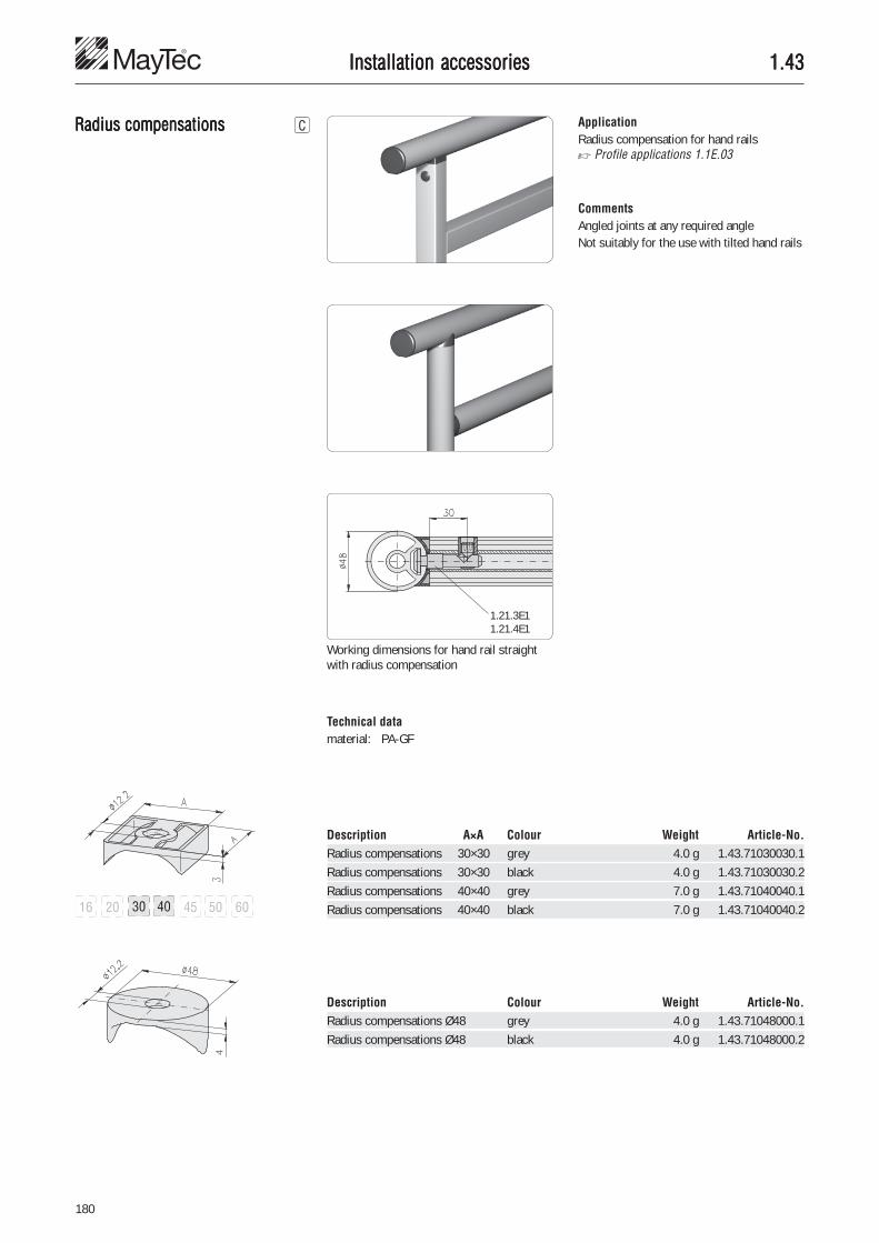
180
1.431.431.431.431.43
1.21.3E11.21.4E1
Description Colour Weight Article-No.Radius compensations Ø48 grey 4.0 g 1.43.71048000.1Radius compensations Ø48 black 4.0 g 1.43.71048000.2
Description A×A Colour Weight Article-No.Radius compensations 30×30 grey 4.0 g 1.43.71030030.1Radius compensations 30×30 black 4.0 g 1.43.71030030.2Radius compensations 40×40 grey 7.0 g 1.43.71040040.1Radius compensations 40×40 black 7.0 g 1.43.71040040.2
Installation accessoriesInstallation accessoriesInstallation accessoriesInstallation accessoriesInstallation accessories
Radius compensationsRadius compensationsRadius compensationsRadius compensationsRadius compensations ApplicationRadius compensation for hand rails� Profile applications 1.1E.03
CommentsAngled joints at any required angleNot suitably for the use with tilted hand rails
Working dimensions for hand rail straightwith radius compensation
Technical datamaterial: PA-GF

181
4
1.441.441.441.441.44Installation accessoriesInstallation accessoriesInstallation accessoriesInstallation accessoriesInstallation accessories
Levelling feetLevelling feetLevelling feetLevelling feetLevelling feet AssemblyFastening in core hole Ø6 mm with threadM8
Technical datamaterial:• plate: PE-HD• screw: steel, galvanisedmax. static load: 2,500 N
Technical datamaterial:• foot plate: PA, black• threaded bolt: steel, galvanisedmax. static load: 500 Nwith anti-slip-disc
Technical datamaterial:• plate: PE-HD• screw: steel, galvanisedmax. static load: 2,500 N
Description Weight Article-No.Floor levelling screw, Ø24, M8×30 22 g 1.44.002403
Description Weight Article-No.Levelling foot, PA, 20 M8×40 24 g 1.44.003020
Description Weight Article-No.Floor levelling screw, SW20, M8×30 20 g 1.44.002003
Fastening in core hole Ø6 mm with threadM8
Fastening in core hole Ø12 with threadedinsert M14/M8

182
1.441.441.441.441.44Installation accessoriesInstallation accessoriesInstallation accessoriesInstallation accessoriesInstallation accessories
Hand adjustable feetHand adjustable feetHand adjustable feetHand adjustable feetHand adjustable feet ApplicationFor manual levelling of benches, tables andlight bases.
Height adjustable alternativeby hand or with tool
Fastening in core hole Fastening in slot
Technical datamaterial:• capsule: PA, black• spindle, nut
and washer: steel galvanisedmax. static load: 1,500 N
Description Weight Article-No.Hand adjustable foot 30 40 g 1.44.203008
Description Weight Article-No.Hand adjustable foot 40 78 g 1.44.204008

183
4
1.441.441.441.441.44Installation accessoriesInstallation accessoriesInstallation accessoriesInstallation accessoriesInstallation accessories
Levelling feetLevelling feetLevelling feetLevelling feetLevelling feet AssemblyFastening in core hole with threaded insertM14/M10
For profiles with core hole-Ø 12 mm
Technical datamaterial:• foot plate: PA, black• cap: steel, galvanised• screw thread: steel, galvanisedmax. static load: 1,500 N
Technical datamaterial:• foot plate: PA, black• cap: steel, galvanised• screw thread: steel, galvanisedmax. static load: 1,500 N
Technical datamaterial:• foot plate: PA, black• screw thread: steel, galvanisedmax. static load: 1,500 N
Description L Weight Article-No.Levelling foot, Ø45, M10×50 60 g 1.44.304505Levelling foot, Ø45, M10×70 69 g 1.44.304507
Description Weight Article-No.Levelling furniture foot, Ø30, M10×18 24 g 1.44.303002
Description Weight Article-No.Levelling foot, Ø35, M10×70 70 g 1.44.303507

184
1.441.441.441.441.44
�
�
�
�
Installation accessoriesInstallation accessoriesInstallation accessoriesInstallation accessoriesInstallation accessories
Adjustable tilt-feetAdjustable tilt-feetAdjustable tilt-feetAdjustable tilt-feetAdjustable tilt-feet ApplicationAdjustable tilt-feet for gradual heightadjustment of sub-assemblies such as:• tables• bases• shelves• stands
Fastening in core holethread M14
Fastening with base plate,for profiles without centriccore hole
Fastening by press-fitthreaded insert across theprofile
Levelling via ball and ball socket ±15°
CommentsInfinitely variable adjustable tilt-feet for useeither with:• anti-slip disc• cushion element
Adjustable tilt-feet - Single parts
� plate • • •
� spindle • •
� nut • •
� anti-slip disc •cushion element •
Pos. Description Material
Adjustable tilt-foot- PA GD-Zn Steel Stainl. steel NBR1.4305

185
4
1.441.441.441.441.44Installation accessoriesInstallation accessoriesInstallation accessoriesInstallation accessoriesInstallation accessories
Adjustable tilt-foot platesAdjustable tilt-foot platesAdjustable tilt-foot platesAdjustable tilt-foot platesAdjustable tilt-foot plateswithout mounting holes
S = height of:• anti-slip disc (S = 2 mm)• cushion element (S = 10 mm)
Design without mounting holes
PA
GD-Zn
Stainless steel
Technical datamaterial:PA: PA-GF, blackGD-Zn: GD-Zn, black powder-coatedstainless: stainless steel 1.4305
F = static load max. in kN
Description D F Weight Article-No.Adjustable tilt-foot plate PA, 30 Ø29 5 kN 8 g 1.44.411030Adjustable tilt-foot plate PA, 40 Ø39 9 kN 13 g 1.44.411040Adjustable tilt-foot plate PA, 45 Ø44 9 kN 15 g 1.44.411045Adjustable tilt-foot plate PA, 50 Ø49 9 kN 16 g 1.44.411050Adjustable tilt-foot plate PA, 60 Ø59 9 kN 22 g 1.44.411060
Adjustable tilt-foot plate GD-Zn, 30 Ø29 20 kN 48 g 1.44.431030Adjustable tilt-foot plate GD-Zn, 40 Ø39 30 kN 70 g 1.44.431040Adjustable tilt-foot plate GD-Zn, 45 Ø44 30 kN 90 g 1.44.431045Adjustable tilt-foot plate GD-Zn, 50 Ø49 30 kN 126 g 1.44.431050Adjustable tilt-foot plate GD-Zn, 60 Ø59 30 kN 160 g 1.44.431060Adjustable tilt-foot plate GD-Zn, 80 Ø79 30 kN 260 g 1.44.431080Adjustable tilt-foot plate GD-Zn, 100 Ø99 35 kN 400 g 1.44.431100Adjustable tilt-foot plate GD-Zn, 120 Ø119 35 kN 584 g 1.44.431120
Adjustable tilt-foot plate, 30 Ø29 20 kN 62 g 1.44.431030VAdjustable tilt-foot plate, 40 Ø39 30 kN 99 g 1.44.431040VAdjustable tilt-foot plate, 45 Ø44 30 kN 123 g 1.44.431045VAdjustable tilt-foot plate, 50 Ø49 35 kN 158 g 1.44.431050VAdjustable tilt-foot plate, 60 Ø59 35 kN 218 g 1.44.431060VAdjustable tilt-foot plate, 80 Ø79 35 kN 380 g 1.44.431080VAdjustable tilt-foot plate, 100 Ø99 40 kN 605 g 1.44.431100VAdjustable tilt-foot plate, 120 Ø119 40 kN 844 g 1.44.431120V

186
1.441.441.441.441.44Installation accessoriesInstallation accessoriesInstallation accessoriesInstallation accessoriesInstallation accessories
Description D d F Weight Article-No.Adjustable tilt-foot plate PA, 80 Ø79 Ø54 9 kN 46 g 1.44.411080Adjustable tilt-foot plate PA, 100 Ø99 Ø74 9 kN 86 g 1.44.411100Adjustable tilt-foot plate PA, 120 Ø119 Ø94 9 kN 104 g 1.44.411120
Description D h d F Weight Article-No.Adjustable tilt-foot plate steel, 80 Ø79 11.5 Ø54 30 kN 260 g 1.44.432080Adjustable tilt-foot plate steel, 100 Ø99 11.5 Ø74 35 kN 377 g 1.44.432100Adjustable tilt-foot plate steel, 120 Ø119 11.5 Ø94 35 kN 570 g 1.44.432120
Adjustable tilt-foot plate stainl., 80 Ø79 11.0 Ø54 30 kN 354 g 1.44.432080VAdjustable tilt-foot plate stainl., 100 Ø99 11.0 Ø74 40 kN 587 g 1.44.432100VAdjustable tilt-foot plate stainl., 120 Ø119 11.0 Ø94 40 kN 830 g 1.44.432120V
Design with mounting holes
CommentsThe holes for fastening screws are closed onthe upper side and can be bored open ifrequired.
Design with mounting holes
CommentsFixing drilling withcounterbore DIN 74 - M8 forcap-screw DIN 6912-M8
Adjustable tilt-foot platesAdjustable tilt-foot platesAdjustable tilt-foot platesAdjustable tilt-foot platesAdjustable tilt-foot plateswith mounting holes
PA
GD-Zn
Stainless steel
S = height of:• anti-slip disc (S = 2 mm)• cushion element (S = 10 mm)
S = height of:• anti-slip disc (S = 2 mm)• cushion element (S = 10 mm)
Technical datamaterial:GD-Zn: GD-Zn, black powder-coatedstainless: stainless steel 1.4305
pickled and passivated
F = static load max. in kN
Technical datamaterial:PA: PA-GF, black
F = static load max. in kN

187
4
1.441.441.441.441.44Installation accessoriesInstallation accessoriesInstallation accessoriesInstallation accessoriesInstallation accessories
Adjustable tilt-foot spindlesAdjustable tilt-foot spindlesAdjustable tilt-foot spindlesAdjustable tilt-foot spindlesAdjustable tilt-foot spindles
Steel
Description G H Weight Article-No.Adjustable tilt-foot nut M8 5 5 g 1.44.46M08Adjustable tilt-foot nut M10 6 8 g 1.44.46M10Adjustable tilt-foot nut M12 7 10 g 1.44.46M12Adjustable tilt-foot nut M14 8 16 g 1.44.46M14Adjustable tilt-foot nut M16 8 17 g 1.44.46M16Adjustable tilt-foot nut M20 9 35 g 1.44.46M20
Adjustable tilt-foot nut, stainless M14 8 16 g 1.44.46M14V
Description G × L SW Weight Article-No.Adjustable tilt-foot spindle, steel M8 × 40 14 17 g 1.44.4608040Adjustable tilt-foot spindle, steel M8 × 80 14 31 g 1.44.4608080Adjustable tilt-foot spindle, steel M10 × 45 14 37 g 1.44.4610045Adjustable tilt-foot spindle, steel M10 × 90 14 51 g 1.44.4610090Adjustable tilt-foot spindle, steel M12 × 66 14 56 g 1.44.4612066Adjustable tilt-foot spindle, steel M12 ×100 14 79 g 1.44.4612100Adjustable tilt-foot spindle, steel M14 × 66 14 87 g 1.44.4614066Adjustable tilt-foot spindle, steel M14 ×100 14 119 g 1.44.4614100Adjustable tilt-foot spindle, steel M14 ×150 14 166 g 1.44.4614150Adjustable tilt-foot spindle, steel M16 × 66 17 111 g 1.44.4616066Adjustable tilt-foot spindle, steel M16 ×100 17 155 g 1.44.4616100Adjustable tilt-foot spindle, steel M16 ×150 17 220 g 1.44.4616150Adjustable tilt-foot spindle, steel M20 ×100 22 237 g 1.44.4620100Adjustable tilt-foot spindle, steel M20 ×150 22 331 g 1.44.4620150
Adjustable tilt-foot spindle, stainless M14 × 66 14 87 g 1.44.4614066VAdjustable tilt-foot spindle, stainless M14 × 88 14 104 g 1.44.4614088VAdjustable tilt-foot spindle, stainless M14 ×100 14 119 g 1.44.4614100VAdjustable tilt-foot spindle, stainless M14 ×125 14 138 g 1.44.4614125VAdjustable tilt-foot spindle, stainless M14 ×150 14 166 g 1.44.4614150V
Adjustable tilt-foot nutsAdjustable tilt-foot nutsAdjustable tilt-foot nutsAdjustable tilt-foot nutsAdjustable tilt-foot nuts
Stainless steel
Stainless steel
Steel
Technical datamaterial:steel: steel, galvanisedstainless: stainless steel 1.4305,
pickled and passivated
Technical datamaterial:steel: steel, galvanisedstainless: stainless steel 1.4305,
pickled and passivated

188
1.441.441.441.441.44Installation accessoriesInstallation accessoriesInstallation accessoriesInstallation accessoriesInstallation accessories
Adjustable tilt-footAdjustable tilt-footAdjustable tilt-footAdjustable tilt-footAdjustable tilt-footanti-slip discsanti-slip discsanti-slip discsanti-slip discsanti-slip discs
Technical datamaterial: NBR, oil and water resistantcolour: blackhardness: 80 Shore AF = static load max. in KN
Description D d F Weight Article-No.Adj. tilt-foot anti-slip disc for plate 30 Ø20 - 5 kN 2.0 g 1.44.471030Adj. tilt-foot anti-slip disc for plate 40 Ø30 - 6 kN 4.0 g 1.44.471040Adj. tilt-foot anti-slip disc for plate 45 Ø35 - 7 kN 5.5 g 1.44.471045Adj. tilt-foot anti-slip disc for plate 50 Ø39 - 8 kN 7.5 g 1.44.471050Adj. tilt-foot anti-slip disc for plate 60 Ø49 - 9 kN 12.0 g 1.44.471060Adj. tilt-foot anti-slip disc for plate 80 Ø67 Ø54 10 kN 22.0 g 1.44.471080Adj. tilt-foot anti-slip disc for plate 100 Ø87 Ø74 10 kN 36.0 g 1.44.471100Adj. tilt-foot anti-slip disc for plate 120 Ø107 Ø94 10 kN 57.0 g 1.44.471120
Adjustable tilt-footAdjustable tilt-footAdjustable tilt-footAdjustable tilt-footAdjustable tilt-footcushion elementscushion elementscushion elementscushion elementscushion elements
Description D F Weight Article-No.Adj. tilt-foot cushion element for plate 40 Ø30 150 N 14 g 1.44.472040Adj. tilt-foot cushion element for plate 45 Ø35 175 N 19 g 1.44.472045Adj. tilt-foot cushion element for plate 50 Ø39 200 N 24 g 1.44.472050Adj. tilt-foot cushion element for plate 60 Ø49 250 N 35 g 1.44.472060Adj. tilt-foot cushion element for plate 80 Ø67 500 N 68 g 1.44.472080Adj. tilt-foot cushion element for plate 100 Ø87 800 N 118 g 1.44.472100Adj. tilt-foot cushion element for plate 120 Ø107 1,200 N 188 g 1.44.472120
ApplicationElement for protection against dislocationand floor damage
Technical datamaterial: NBR, oil and water resistantcolour: blackhardness: 70 Shore AF = static load max. in N
ApplicationCushion elements

189
4
1.441.441.441.441.44Installation accessoriesInstallation accessoriesInstallation accessoriesInstallation accessoriesInstallation accessories
Angular adjusting feetAngular adjusting feetAngular adjusting feetAngular adjusting feetAngular adjusting feet ApplicationFor fastening of frames to floor or wall
Technical datamaterial:• base body: GD-Al, black• nuts: steel galvanised• screws: steel galvanisedmax. static load: 10,000 N
Delivery unit• base body• nut M8• screw M8×16 - 10.9
Description Weight Article-No.Angular adjusting foot without adjusting screw 468 g 1.44.716001
Description Weight Article-No.Angular adjusting foot with adjusting screw 519 g 1.44.716002
Delivery unit:• base body• nut M8• screw M8×16 - 10.9• screw M8×80 - 10.9• square nut

190
1.441.441.441.441.44Installation accessoriesInstallation accessoriesInstallation accessoriesInstallation accessoriesInstallation accessories
Base footBase footBase footBase footBase footfor profile 40×40
ApplicationBase feet for fastening profiles and framesto floor or wall
Technical datamaterial: GD-Zn
Description Weight Article-No.Base foot for profile 40×40 979 g 1.44.83040
Description Weight Article-No.Floor mounting set 3 MKT 202.3 g 1.44.83BB
Single parts Pcs. Weight Article-No.Pin anchor MKT, B10/20/95 3 65.3 g 0.66.MKT.B1020/95Plain washer 1×Ø24/11 8 0.8 g 1.44.89011324Drilling depth min. 70 mm
Plain washers for verticalalignment as required
Floor mounting set

191
4
1.441.441.441.441.44Installation accessoriesInstallation accessoriesInstallation accessoriesInstallation accessoriesInstallation accessories
Base feetBase feetBase feetBase feetBase feet ApplicationBase feet for fastening profiles and framesto floor or wall
Technical datamaterial: GK AlZn 10Si8Mg
Description for profile Weight Article-No.Base foot 40×40, type 1, left 40×40, 45×45 1.06 kg 1.44.84.4040.00LBase foot 40×40, type 1, right 40×40, 45×45 1.06 kg 1.44.84.4040.00R
Description for profile Weight Article-No.Base foot 40×40, type 2, left 40×40 0.83 kg 1.44.84.4040.40LBase foot 40×40, type 2, right 40×40 0.83 kg 1.44.84.4040.40R
40×40, type 1, left 40×40, type 1, right
40×40, type 2, left 40×40, type 2, right
Comments3D picture shows type 2, rightmirror-inverted: type 2, left
Comments3D picture shows type 1, rightmirror-inverted: type 1, left
Mounting sets (����� 194, 195)Floor mounting set 4 MKTProfile mounting set 4 EM8
Mounting sets (����� 194, 195)Floor mounting set 3 MKTProfile mounting set 4 EM8

192
1.441.441.441.441.44Installation accessoriesInstallation accessoriesInstallation accessoriesInstallation accessoriesInstallation accessories
Description for profile Weight Article-No.Base foot 40×80, type 1, left 40×80, 60×80, 45×90 1.39 kg 1.44.84.4080.00LBase foot 40×80, type 1, right 40×80, 60×80, 45×90 1.39 kg 1.44.84.4080.00R
Description for profile Weight Article-No.Base foot 40×80, type 2, left 40×80 1.01 kg 1.44.84.4080.40LBase foot 40×80, type 2, right 40×80 1.01 kg 1.44.84.4080.40R
40×80, type 1, left 40×80, type 1, right
40×80, type 2, left 40×80, type 2, right
Comments3D picture shows type 2, rightmirror-inverted: type 2, left
Comments3D picture shows type 1, rightmirror-inverted: type 1, left
Description for profile Weight Article-No.Base foot 45×45, type 2, left 45×45 0.85 kg 1.44.84.4545.45LBase foot 45×45, type 2, right 45×45 0.85 kg 1.44.84.4545.45R
45×45, type 2, left 45×45, type 2, right
Comments3D picture shows type 2, rightmirror-inverted: type 2, left
Mounting sets (����� 194, 195)Floor mounting set 4 MKTProfile mounting set 6 EM8
Mounting sets (����� 194, 195)Floor mounting set 3 MKTProfile mounting set 6 EM8
Mounting sets (����� 194, 195)Floor mounting set 3 MKTProfile mounting set 4 EM8

193
4
1.441.441.441.441.44
Description for profile Weight Article-No.Base foot 60×80, type 2, left 60×80 1.25 kg 1.44.84.6080.60LBase foot 60×80, type 2, right 60×80 1.25 kg 1.44.84.6080.60R
Description for profile Weight Article-No.Base foot 45×90, type 2, left 45×90 1.10 kg 1.44.84.4590.45LBase foot 45×90, type 2, right 45×90 1.10 kg 1.44.84.4590.45R
60×80, type 2, left 60×80, type 2, right
45×90, type 2, left 45×90, type 2, right
Comments3D picture shows type 2, rightmirror-inverted: type 2, left
Comments3D picture shows type 2, rightmirror-inverted: type 2, left
Installation accessoriesInstallation accessoriesInstallation accessoriesInstallation accessoriesInstallation accessories
Mounting sets (����� 194, 195)Floor mounting set 3 MKTProfile mounting set 6 EM8
Mounting sets (����� 194, 195)Floor mounting set 3 MKTProfile mounting set 6 EM8

194
1.441.441.441.441.44Installation accessoriesInstallation accessoriesInstallation accessoriesInstallation accessoriesInstallation accessories
Floor mounting sets Cross-reference list for base feet and floor mounting sets
Description Weight Article-No.Floor mounting set 4 MKT 269.2 g 1.44.84BB
Single parts Pcs. Weight Article-No.Pin anchor MKT, B10/20/95 4 65.3 g 0.66.MKT.B1020/95Plain washer 1×Ø24/11 10 0.8 g 1.44.89011324
Description Weight Article-No.Floor mounting set 3 MKT 202.3 g 1.44.83BB
Single parts Pcs. Weight Article-No.Pin anchor MKT, B10/20/95 3 65.3 g 0.66.MKT.B1020/95Plain washer 1×Ø24/11 8 0.8 g 1.44.89011324
Base foot Article-No. Floor mounting set
3 MKT, 1.44.83BB 4 MKT, 1.44.84BB
40×40, type 1, le/ri 1.44.84.4040.00x •40×40, type 2, le/ri 1.44.84.4040.40x •40×80, type 1, le/ri 1.44.84.4080.00x •40×80, type 2, le/ri 1.44.84.4080.40x •45×45, type 2, le/ri 1.44.84.4545.45x •45×90, type 2, le/ri 1.44.84.4590.45x •60×80, type 2, le/ri 1.44.84.6080.60x •
Comments• Drilling depth min. 70 mm• Plain washers for vertical
alignment as required

195
4
1.441.441.441.441.44Installation accessoriesInstallation accessoriesInstallation accessoriesInstallation accessoriesInstallation accessories
Profile mounting sets
Description Weight Article-No.Profile mounting set 4 EM8 112.4 g 1.44.80BP40.20
Single parts Pcs. Weight Article-No.Threaded plate, heavy, E M8 4 16.3 g 1.31.6EM8Collar screw WN 251 M8×20 4 11.8 g 0.63.WN0251.08020
ApplicationSuitable for mounting of the profiles:• 40×40• 45×45
Description Weight Article-No.Profile mounting set 6 EM8 168.6 g 1.44.80BP80.20
Single parts Pcs. Weight Article-No.Threaded plate, heavy, E M8 6 16.3 g 1.31.6EM8Collar screw WN 251 M8×20 6 11.8 g 0.63.WN0251.08020
ApplicationSuitable for mounting of the profiles:• 40×80• 45×90• 60×80, panel

196
1.441.441.441.441.44Installation accessoriesInstallation accessoriesInstallation accessoriesInstallation accessoriesInstallation accessories
Base angleBase angleBase angleBase angleBase angle ApplicationFor fastening of frames to floor or wall
Technical datamaterial: sheet steelsurface: galvanised and black coated
Stacking footStacking footStacking footStacking footStacking foot ApplicationElement to fix 2 profiles in core hole
Technical datamaterial: steelsurface: galvanised
Suitable for use together with levelling feetwith max. diameter 100 mm
Description Weight Article-No.Base angle 200×87×42 413 g 1.44.820001
Description Weight Article-No.Stacking foot 19 g 1.44.901221
Top side guidedloosely
Bottom sidedriven in

197
4
1.451.451.451.451.45
s = 7 mm
s = 2 mm
s = 10.5 mm
s = 3 mm
Fastening through baseplate for profile withoutcentric core hole
Installation accessoriesInstallation accessoriesInstallation accessoriesInstallation accessoriesInstallation accessories
CastorsCastorsCastorsCastorsCastors
Fastening in core hole Fastening by press-fitthreaded insert across theprofile
Fixed castors
Description D a Weight Article-No.Fixed castor with bolt hole Ø50 69 130 g 1.45.11050Fixed castor with bolt hole Ø75 98 240 g 1.45.11075Fixed castor with bolt hole Ø100 133 500 g 1.45.11100Fixed castor with bolt hole Ø125 158 900 g 1.45.11125
Fixed castor with fitting plate Ø50 71 190 g 1.45.12050Fixed castor with fitting plate Ø75 100 300 g 1.45.12075Fixed castor with fitting plate Ø100 136 610 g 1.45.12100Fixed castor with fitting plate Ø125 161 1,010 g 1.45.12125
Technical datamaterial:• capsule: sheet steel, galvanised• wheels: solid rubber tyres, grey
Ø75/100/125 incl. thread protectionmax. static load: Fmax
Design bolt hole
Variations
Castor-Ø 50 mm / 75 mm 100 mm / 125 mm
Bolt hole type
Fitting plate type
Ø50 30 27 Ø10.5 18 2.0 400 N
Ø75 34 27 Ø10.5 25 2.0 550 N
Ø100 57 43 Ø12.5 32 2.5 800 N
Ø125 57 43 Ø12.5 32 2.5 1,000 N
D b c d e s Fmax

198
1.451.451.451.451.45Installation accessoriesInstallation accessoriesInstallation accessoriesInstallation accessoriesInstallation accessories
Swivel castors Technical datamaterial:• capsule: sheet steel, galvanised• wheels: solid rubber tyres, grey
Ø75/100/125 incl. thread protectionmax. static load: Fmax
Technical datamaterial:• capsule: sheet steel, galvanised• wheels: solid rubber tyres, grey
stop fix: - wheel break- swivel break
Ø75/100/125 incl. thread protectionmax. static load: Fmax
Swivel castors lockable
Description D a Weight Article-No.Swivel castor with bolt hole Ø50 69 180 g 1.45.21050Swivel castor with bolt hole Ø75 98 310 g 1.45.21075Swivel castor with bolt hole Ø100 133 680 g 1.45.21100Swivel castor with bolt hole Ø125 158 890 g 1.45.21125
Swivel castor with fitting plate Ø50 71 230 g 1.45.22050Swivel castor with fitting plate Ø75 100 360 g 1.45.22075Swivel castor with fitting plate Ø100 136 780 g 1.45.22100Swivel castor with fitting plate Ø125 161 990 g 1.45.22125Dimensions see table below
Description D a Weight Article-No.Swivel castor, lockable with bolt hole Ø50 69 220 g 1.45.31050Swivel castor, lockable with bolt hole Ø75 98 450 g 1.45.31075Swivel castor, lockable with bolt hole Ø100 133 840 g 1.45.31100Swivel castor, lockable with bolt hole Ø125 158 990 g 1.45.31125
Swivel castor, lockable with fitting plate Ø50 71 270 g 1.45.32050Swivel castor, lockable with fitting plate Ø75 100 500 g 1.45.32075Swivel castor, lockable with fitting plate Ø100 136 940 g 1.45.32100Swivel castor, lockable with fitting plate Ø125 161 1,090 g 1.45.32125
Design bolt hole
Ø50 25 Ø43 Ø10.5 18 10.5 400 N
Ø75 30.5 Ø43 Ø10.5 25 10.5 550 N
Ø100 43 Ø57 Ø12.5 32 10.5 800 N
Ø125 43 Ø57 Ø12.5 32 10.5 1,000 N
D b c d e s Fmax

199
4
1.451.451.451.451.45
s = 7 mm s = 8 mm
Installation accessoriesInstallation accessoriesInstallation accessoriesInstallation accessoriesInstallation accessories
Locking castorsLocking castorsLocking castorsLocking castorsLocking castors ApplicationLocking castors for easy movement andpositioning of trolleys, benches andassemblies
Extended support foot to secure position Retracted support foot for easy movement
Technical datamaterial:• capsule: Al• fastening elements: C45• locking foot: GD-Al, rubbermax. static load: Fmax
Ø50 83 93 98 10 2,000 N
Ø62 102 117 122 15 4,000 N
Design
D a bmax c Hmax Fmax
Castor-Ø50 Castor-Ø62
Description D Weight Article-No.Locking castor 200 kg, with plate Ø50 760 g 1.45.80200.073Locking castor 400 kg, with plate Ø62 1,380 g 1.45.80400.090
Mounting on profile frame using core holeand slot
Locking castorswith plate

200
1.451.451.451.451.45Installation accessoriesInstallation accessoriesInstallation accessoriesInstallation accessoriesInstallation accessories
Fastening through baseplate for profiles withoutcentral core hole
Fastening in core hole Fastening with press-fitthreaded insert and baseplate across the profile
Locking castorswith center thread
Castor-Ø50 Castor-Ø62
Threaded bolt for fastening in core hole Threaded bolt for fastening with base plate
Threaded boltfor locking castorwith center thread
Description Weight Article-No.Threaded bolt M16/M14 28 g 1.45.81000.M16M14
ApplicationFor fastening of locking castors with centralthread• in core hole-Ø12 of the profile• on base plate
Description D Weight Article-No.Locking castor 200 kg, with center thread Ø50 760 g 1.45.81200.046Locking castor 400 kg, with center thread Ø62 1,380 g 1.45.81400.065
Technical datamaterial: steelsurface: galvanised

201
4
1.461.461.461.461.46Installation accessoriesInstallation accessoriesInstallation accessoriesInstallation accessoriesInstallation accessories
Angles 25×40Angles 25×40Angles 25×40Angles 25×40Angles 25×40
Technical datamaterial: aluminiumstrength: F22surface: natural anodised
ApplicationAngle bracket for the mounting of panels,table tops, switches and accessories
Fastening of panels
Fastening of table tops
CommentsDesign with clearance hole drilling
CommentsDesign with nut M6 ± 0.5 mm floating incage
Description D Weight Article-No.Angle 25×40 Ø6.6 11 g 1.46.110Angle 25×40 Ø8.7 10 g 1.46.115
Description Weight Article-No.Angle 25×40, M6 15 g 1.46.120

202
1.461.461.461.461.46Installation accessoriesInstallation accessoriesInstallation accessoriesInstallation accessoriesInstallation accessories
Angles PAngles PAngles PAngles PAngles PAAAAA ApplicationFor supporting of profiles and mounting ofcover panels
Support of free-standing profiles
Support across the profileIn this application the rotary lock must beremoved from one side
Mounting of cover panelsIn this application the rotary lock must beremoved from both sides
Technical datamaterial: PA-GF
20×28
30×38
Description Colour Weight Article-No.Angle PA, 20×28 grey 6.4 g 1.46.203.2028.1Angle PA, 20×28 black 6.4 g 1.46.203.2028.2
Description Colour Weight Article-No.Angle PA, 30×38 grey 18.9 g 1.46.203.3038.1Angle PA, 30×38 black 18.9 g 1.46.203.3038.2

203
4
1.461.461.461.461.46
Angles GD-ZnAngles GD-ZnAngles GD-ZnAngles GD-ZnAngles GD-Zn ApplicationFor supporting profiles and mountingvarious machine components
Technical datamaterial:• angle: GD-Zn• cover cap: PA-GK 30• T-slot nut: steel, galvanised• screw: steel, galvanisedsurface: natural or aluminium
coloured powder-coated
17×20Description Surface Weight Article-No.Angle GD-Zn, 17×20 natural 13.7 g 1.46.204.1720.1Angle GD-Zn, 17×20 powder-coated 13.7 g 1.46.204.1720.2
Cover cap for angle GD-Zn, 17×20 1.7 g 1.46.204.1720A
Angle connection set 1720 H/H 20.9 g 1.46.204.1720.�HHAngle connection set 1720 H/F 23.6 g 1.46.204.1720.�HFAngle connection set 1720 F/F 26.3 g 1.46.204.1720.�FF
Angle connection set 1720 T H/F 25.0 g 1.46.204.1720T�HFAngle connection set 1720 T F/F 29.1 g 1.46.204.1720T�FF
H threaded plate lens head screw Pcs.
F T-slot nut
1.46.204.1720.� H H 1.31.4HM5 0.63.WN7381.05006 2
1.46.204.1720.� H 1.31.4HM5 0.63.WN7381.05006 1F 1.34.10FM5 0.63.WN7381.05008 1
1.46.204.1720.� F F 1.34.10FM5 0.63.WN7381.05008 2
For mounting cross to the slot the noses canbe broken off
Installation accessoriesInstallation accessoriesInstallation accessoriesInstallation accessoriesInstallation accessories
Single parts: Angle connection sets 1720
Angle Slot Fastening elements
H threaded plate lens head screw Pcs.
F T-nut for subs.insertion
1.46.204.1720� H 1.31.4HM5 0.63.WN7381.05006 1F 1.32.4FM5 0.63.WN7381.05008 1
1.46.204.1720� F F 1.32.4FM5 0.63.WN7381.05008 2
Single parts: Angle connection sets 1720 T
Angle Slot Fastening elements
�1 angle natural2 angle powder-coated

204
1.461.461.461.461.46
28×28
Description Surface Weight Article-No.Angle GD-Zn, 28×28 natural 39.6 g 1.46.204.2828.1Angle GD-Zn, 28×28 powder-coated 39.6 g 1.46.204.2828.2
Cover cap for angle GD-Zn, 28×28 5.6 g 1.46.204.2828A
Angle connection set 2828 F/F 56.4 g 1.46.204.2828.�FFAngle connection set 2828 F/E 56.8 g 1.46.204.2828.�FEAngle connection set 2828 E/E 57.2 g 1.46.204.2828.�EE
Angle connection set 2828 T F/F 59.8 g 1.46.204.2828T�FFAngle connection set 2828 T F/E 66.3 g 1.46.204.2828T�FEAngle connection set 2828 T E/E 72.8 g 1.46.204.2828T�EE
�1 angle natural2 angle powder-coated
T-slot nut lens head screw Pcs.
1.46.204.2828.� F F 1.34.10FM6 0.63.WN7381.06010 2
1.46.204.2828.� F 1.34.10FM6 0.63.WN7381.06010 1E 1.34.10EM6 0.63.WN7381.06012 1
1.46.204.2828.� E E 1.34.10EM6 0.63.WN7381.06012 2
Single parts: Angle connection sets 2828
Angle Slot Fastening elements
T-nut for subs. lens head screw Pcs.insertion
1.46.204.2828� F F 1.32.4FM6 0.63.WN7381.06010 2
1.46.204.2828� F 1.32.4FM6 0.63.WN7381.06010 1E 1.32.4EM6 0.63.WN7381.06012 1
1.46.204.2828� E E 1.32.4EM6 0.63.WN7381.06012 2
Installation accessoriesInstallation accessoriesInstallation accessoriesInstallation accessoriesInstallation accessories
Single parts: Angle connection sets 2828 T
Angle Slot Fastening elements

205
4
1.461.461.461.461.46
40×39
Description Surface Weight Article-No.Angle GD-Zn, 40×39 natural 85.5 g 1.46.204.4039.1Angle GD-Zn, 40×39 powder-coated 85.5 g 1.46.204.4039.2
Cover cap for angle GD-Zn, 40×39 8.0 g 1.46.204.4039A
Angle connection set 4039 F/F 105.9 g 1.46.204.4039.�FFAngle connection set 4039 F/E 111.9 g 1.46.204.4039.�FEAngle connection set 4039 E/E 117.9 g 1.46.204.4039.�EE
Angle connection set 4039 T F/F 105.9 g 1.46.204.4039T�FFAngle connection set 4039 T F/E 111.9 g 1.46.204.4039T�FEAngle connection set 4039 T E/E 117.9 g 1.46.204.4039T�EE
�1 angle natural2 angle powder-coated
T-screw hexagon flange nut Pcs.
1.46.204.4039.� F F 1.34.FM82 0.61.D06923.08 2
1.46.204.4039.� F 1.34.FM82 0.61.D06923.08 1E 1.34.EM82 0.61.D06923.08 1
1.46.204.4039.� E E 1.34.EM82 0.61.D06923.08 2
Single parts: Angle connection sets 4039
Angle Slot Fastening elements
T-nut for subs. lens head screw Pcs.insertion
1.46.204.4039� F F 1.32.4FM8 0.63.WN7381.08012 2
1.46.204.4039� F 1.32.4FM8 0.63.WN7381.08012 1E 1.32.4EM8 0.63.WN7381.08016 1
1.46.204.4039� E E 1.32.4EM8 0.63.WN7381.08016 2
Connection with T-screw only without covercap
1)
1)
Installation accessoriesInstallation accessoriesInstallation accessoriesInstallation accessoriesInstallation accessories
Single parts: Angle connection sets 4039 T
Angle Slot Fastening elements

206
1.461.461.461.461.46
38×76
Description Surface Weight Article-No.Angle GD-Zn, 38×76 natural 273.0 g 1.46.204.3876.1Angle GD-Zn, 38×76 powder-coated 273.0 g 1.46.204.3876.2
Cover cap for angle GD-Zn, 38×76 16.8 g 1.46.204.3876A
Angle connection set 3876 F/F 334.2 g 1.46.204.3876.�FFAngle connection set 3876 F/E 342.2 g 1.46.204.3876.�FEAngle connection set 3876 E/E 350.2 g 1.46.204.3876.�EE
Angle connection set 3876 T F/F 313.8 g 1.46.204.3876T�FFAngle connection set 3876 T F/E 325.8 g 1.46.204.3876T�FEAngle connection set 3876 T E/E 337.8 g 1.46.204.3876T�EE
�1 angle natural2 angle powder-coated
T-screw hexagon flange nut Pcs.
1.46.204.3876.� F F 1.34.FM82 0.61.D06923.08 4
1.46.204.3876.� F 1.34.FM82 0.61.D06923.08 2E 1.34.EM82 0.61.D06923.08 2
1.46.204.3876.� E E 1.34.EM82 0.61.D06923.08 4
Single parts: Angle connection sets 3876
Angle Slot Fastening elements
T-nut for subs. lens head screw Pcs.insertion
1.46.204.3876� F F 1.32.4FM8 0.63.WN7381.08012 4
1.46.204.3876� F 1.32.4FM8 0.63.WN7381.08012 2E 1.32.4EM8 0.63.WN7381.08016 2
1.46.204.3876� E E 1.32.4EM8 0.63.WN7381.08016 4
Installation accessoriesInstallation accessoriesInstallation accessoriesInstallation accessoriesInstallation accessories
Single parts: Angle connection sets 3876 T
Angle Slot Fastening elements

207
4
1.461.461.461.461.46
57×57
Description Surface Weight Article-No.Angle GD-Zn, 57×57 natural 226.3 g 1.46.204.5757.1Angle GD-Zn, 57×57 powder-coated 226.3 g 1.46.204.5757.2
Cover cap for angle GD-Zn, 57×57 22.8 g 1.46.204.5757A
Angle connection set 5757 F/F 296.7 g 1.46.204.5757.�FFAngle connection set 5757 F/E 280.8 g 1.46.204.5757.�FEAngle connection set 5757 E/E 261.9 g 1.46.204.5757.�EE
Angle connection set 5757 T F/F 246.7 g 1.46.204.5757T�FFAngle connection set 5757 T F/E 252.7 g 1.46.204.5757T�FEAngle connection set 5757 T E/E 258.7 g 1.46.204.5757T�EE
F T-slot nut lens head screw Pcs.
E T-screw hexagon flange nut
1.46.204.5757.� F F 1.34.10FM6 0.63.WN7381.06012 8
1.46.204.5757.� F 1.34.10FM6 0.63.WN7381.06012 4E 1.34.EM82 0.61.D06923.08 1
1.46.204.5757.� E E 1.34.EM82 0.61.D06923.08 2
Single parts: Angle connection sets 5757
Angle Slot Fastening elements
�1 angle natural2 angle powder-coated
T-nut for subs. lens head screw Pcs.insertion
1.46.204.5757� F F 1.32.4FM6 0.63.WN7381.06012 8
1.46.204.5757� F 1.32.4FM6 0.63.WN7381.06012 4E 1.32.4EM8 0.63.WN7381.08016 1
1.46.204.5757� E E 1.32.4EM8 0.63.WN7381.08016 2
Installation accessoriesInstallation accessoriesInstallation accessoriesInstallation accessoriesInstallation accessories
Single parts: Angle connection sets 5757 T
Angle Slot Fastening elements

208
1.461.461.461.461.46
74×76
Description Surface Weight Article-No.Angle GD-Zn, 74×76 natural 434.5 g 1.46.204.7476.1Angle GD-Zn, 74×76 powder-coated 434.5 g 1.46.204.7476.2
Cover cap for angle GD-Zn, 74×76 32.7 g 1.46.204.7476A
Angle connection set 7476 E/E 588.9 g 1.46.204.7476.�EE
�1 angle natural2 angle powder-coated
T-screw hexagon flange nut Pcs.
1.46.204.7476.� E E 1.34.EM82 0.61.D06923.08 8
Single parts: Angle connection set 7476
Angle Slot Fastening elements
Installation accessoriesInstallation accessoriesInstallation accessoriesInstallation accessoriesInstallation accessories
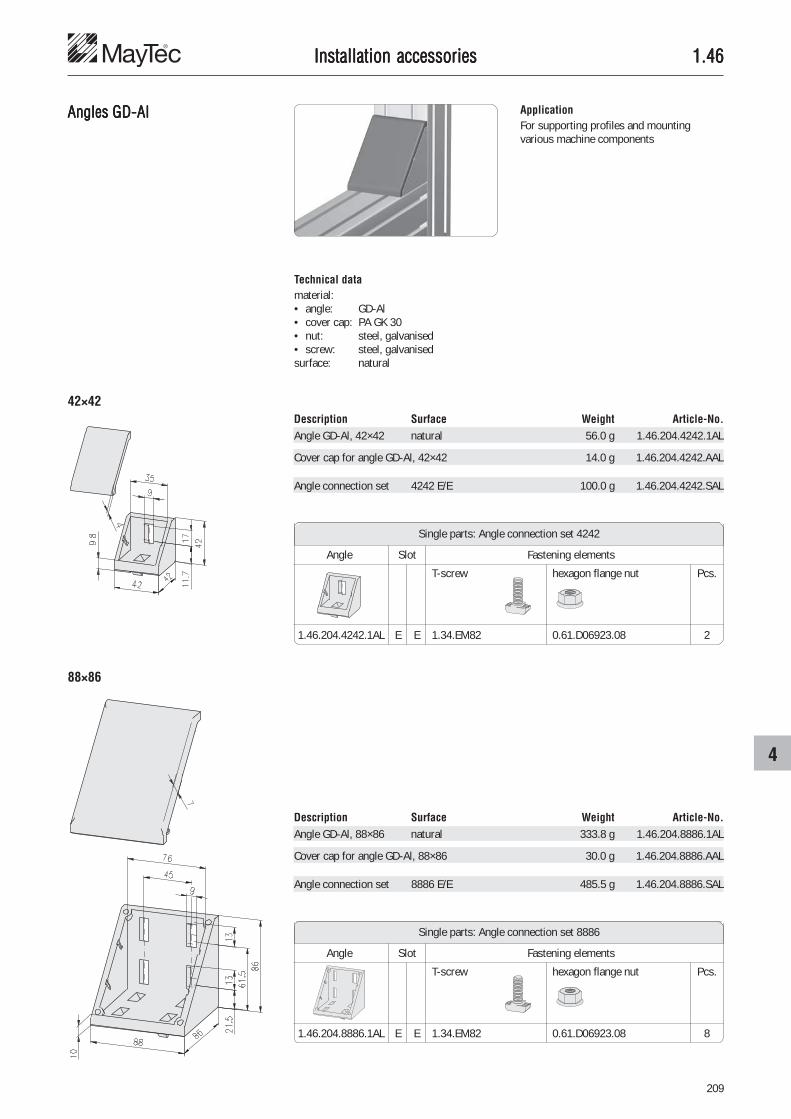
209
4
1.461.461.461.461.46
Description Surface Weight Article-No.Angle GD-Al, 88×86 natural 333.8 g 1.46.204.8886.1AL
Cover cap for angle GD-Al, 88×86 30.0 g 1.46.204.8886.AAL
Angle connection set 8886 E/E 485.5 g 1.46.204.8886.SAL
T-screw hexagon flange nut Pcs.
1.46.204.8886.1AL E E 1.34.EM82 0.61.D06923.08 8
Single parts: Angle connection set 8886
Angle Slot Fastening elements
Angles GD-AlAngles GD-AlAngles GD-AlAngles GD-AlAngles GD-Al ApplicationFor supporting profiles and mountingvarious machine components
Technical datamaterial:• angle: GD-Al• cover cap: PA GK 30• nut: steel, galvanised• screw: steel, galvanisedsurface: natural
42×42
88×86
Description Surface Weight Article-No.Angle GD-Al, 42×42 natural 56.0 g 1.46.204.4242.1AL
Cover cap for angle GD-Al, 42×42 14.0 g 1.46.204.4242.AAL
Angle connection set 4242 E/E 100.0 g 1.46.204.4242.SAL
T-screw hexagon flange nut Pcs.
1.46.204.4242.1AL E E 1.34.EM82 0.61.D06923.08 2
Single parts: Angle connection set 4242
Angle Slot Fastening elements
Installation accessoriesInstallation accessoriesInstallation accessoriesInstallation accessoriesInstallation accessories

210
1.461.461.461.461.46Installation accessoriesInstallation accessoriesInstallation accessoriesInstallation accessoriesInstallation accessories
Angles AluAngles AluAngles AluAngles AluAngles Alu ApplicationFor supporting of profiles and mounting ofcover panels
Mounting of cover panels
Support across the profile Support of free-standing profiles
Technical datamaterial: aluminiumstrength: F22surface: natural anodised
48×48
60×60
100×100
Description D B Weight Article-No.Angle 48×48 Ø6.6 30 40 g 1.46.20536Angle 48×48 Ø9.0 30 38 g 1.46.20539Angle 48×48 Ø6.6 45 66 g 1.46.20546Angle 48×48 Ø9.0 45 64 g 1.46.20549
Description D B Weight Article-No.Angle 60×60 Ø9.0 30 49 g 1.46.20639Angle 60×60 Ø9.0 45 74 g 1.46.20649
Description D B Weight Article-No.Angle 100×100 Ø6.6 30 95 g 1.46.21036Angle 100×100 Ø9.0 30 93 g 1.46.21039Angle 100×100 Ø6.6 45 155 g 1.46.21046Angle 100×100 Ø9.0 45 153 g 1.46.21049
CommentsAngles Alu are made from the angle profiles� 1.19.141...

211
4
1.461.461.461.461.46Installation accessoriesInstallation accessoriesInstallation accessoriesInstallation accessoriesInstallation accessories
Swivel anglesSwivel anglesSwivel anglesSwivel anglesSwivel angles
ApplicationInfinitely variable adjusting of inclinationwith swivel angle
Fastening from below
Description L Design a b Weight Article-No.Swivel angle 131 alu 8 8.0 105 g 1.46.3012900.ALSwivel angle 146 alu 13 10.5 116 g 1.46.3014400.AL
Swivel angle 131 steel 8 8.0 320 g 1.46.3012900.STSwivel angle 146 steel 13 10.5 360 g 1.46.3014400.ST
Technical dataDesign alu:• material: aluminium• strength: F22• surface: natural anodised
Design steel:• material: steel• surface: galvanised
Fastening from the side
Description Design Weight Article-No.Swivel angle 30 alu 105 g 1.46.3110530.AL
Swivel angle 30 steel 320 g 1.46.3110530.ST

212
1.46 - 1.471.46 - 1.471.46 - 1.471.46 - 1.471.46 - 1.47
Hmax
Installation accessoriesInstallation accessoriesInstallation accessoriesInstallation accessoriesInstallation accessories
Cross connection platesCross connection platesCross connection platesCross connection platesCross connection plates
ApplicationThe cross connection plate allows profileadjustment in 2 directions and at an angleof ±45°
Technical datamaterial: aluminiumstrength: F22surface: natural anodised
Description Hmax Weight Article-No.Cross connection plate 65×65 20 20 g 1.47.1065Cross connection plate 85×85 30 35 g 1.47.1085Cross connection plate 95×95 30 45 g 1.47.1095Cross connection plate 125×125 50 80 g 1.47.1125
Type A a b ØD Ød
65×65 65 18 5.1 45 5.1
85×85 85 18 5.1 60 5.1
95×95 95 18 6.1 65 6.1
125×125 125 37 8.1 95 8.1
Description Design Weight Article-No.Swivel angle 45 alu 116 g 1.46.3110545.AL
Swivel angle 45 steel 360 g 1.46.3110545.ST

213
4
1.471.471.471.471.47Installation accessoriesInstallation accessoriesInstallation accessoriesInstallation accessoriesInstallation accessories
Base platesBase platesBase platesBase platesBase plates ApplicationBase and transporting plate for profileswithout centric core hole
Fastening of levelling feet
Fastening of castors Fastening of eye-bolts
Technical dataDesign Alu:• material: aluminium• strength: F22• surface: black powder-coated
Design GD-Zn:• material: GD-Zn• surface: black powder-coated
Accessories• threaded insert• cap-screw DIN 912
CommentsCounterbore DIN 74 forcap-screw DIN 912
Variants
without thread with thread
Dimensions without thread with thread M14B×L Design h Article-No. Design h Article-No.
30×60 Alu 15 1.47.2030060.0600.1 GD-Zn 12 1.47.2030640×80 Alu 15 1.47.2040080.0800.1 GD-Zn 16 1.47.2040845×90 Alu 15 1.47.2045090.0800.1 GD-Zn 16 1.47.2045090
50×100 Alu 15 1.47.2050100.0800.1 GD-Zn 16 1.47.2051060×90 Alu 15 1.47.2060090.0800.1 Alu 15 1.47.2060090
50×150 Alu 15 1.47.2050150.0800.1
60×60 Alu 15 1.47.2060060.0800.1 GD-Zn 12 1.47.206006080×80 Alu 15 1.47.2080080.0800.1 GD-Zn 16 1.47.2080890×90 Alu 15 1.47.2090090.0800.1 GD-Zn 16 1.47.2090090
100×100 Alu 15 1.47.2100100.0800.1 GD-Zn 16 1.47.21010

214
1.471.471.471.471.47
counterbore DIN 74
counterbore DIN 74
Description B×L Design h a Weight Article-No.Base plate 30×60 GD-Zn M14 M6 12 30 104.2 g 1.47.20306Base plate 40×80 GD-Zn M14 M8 16 40 205.2 g 1.47.20408Base plate 45×90 GD-Zn M14 M8 16 45 256.5 g 1.47.2045090Base plate 50×100 GD-Zn M14 M8 16 50 316.8 g 1.47.20510Base plate 60×90 Alu M14 M8 15 45 197.1 g 1.47.2060090
Description B×L Design h a Weight Article-No.Base plate 60×60 GD-Zn M14 M8 12 30 158.4 g 1.47.2060060Base plate 80×80 GD-Zn M14 M8 16 40 434.3 g 1.47.20808Base plate 90×90 GD-Zn M14 M8 16 45 520.7 g 1.47.2090090Base plate 100×100 GD-Zn M14 M8 16 50 601.0 g 1.47.21010
Installation accessoriesInstallation accessoriesInstallation accessoriesInstallation accessoriesInstallation accessories
counterbore DIN 74
Description B×L Design DIN 74 h a Weight Article-No.Base plate w/o thread 30×60 Alu - Km6 15 30 64 g 1.47.2030060.0600.1Base plate w/o thread 40×80 Alu - Km8 15 40 114 g 1.47.2040080.0800.1Base plate w/o thread 45×90 Alu - Km8 15 45 148 g 1.47.2045090.0800.1Base plate w/o thread 50×100 Alu - Km8 15 50 186 g 1.47.2050100.0800.1Base plate w/o thread 60×90 Alu - Km8 15 45 202 g 1.47.2060090.0800.1
counterbore DIN 74
Description B×L Design DIN 74 h a Weight Article-No.Base plate w/o thread 60×60 Alu - Km8 15 30 115 g 1.47.2060060.0800.1Base plate w/o thread 80×80 Alu - Km8 15 40 228 g 1.47.2080080.0800.1Base plate w/o thread 90×90 Alu - Km8 15 45 297 g 1.47.2090090.0800.1Base plate w/o thread 100×100 Alu - Km8 15 50 374 g 1.47.2100100.0800.1
Base plateswithout thread
Description B×L Design DIN 74 h a Weight Article-No.Base plate w/o thread 50×150 Alu - Km8 15 100 280 g 1.47.2050150.0800.1
counterbore DIN 74
Base plateswith thread

215
4
1.471.471.471.471.47
Floor mounting plateFloor mounting plateFloor mounting plateFloor mounting plateFloor mounting plate
Installation accessoriesInstallation accessoriesInstallation accessoriesInstallation accessoriesInstallation accessories
ApplicationFor fastening and manual levelling of profileracks and frames
Description Weight Article-No.Floor mounting plate, natural 622 g 1.47.225160.1Floor mounting plate, black powder-coated 622 g 1.47.225160.2
Technical datamaterial: aluminiumsurface: natural or black powder-
coated
Fastening elementsF-slot: 2×T-nut with leaf spring FM8 1.32.FM8
2×cap screw M8×25
E-slot: 2×threaded plate, heavy EM8 1.31.6EM82×cap screw M8×30

216
1.471.471.471.471.47Installation accessoriesInstallation accessoriesInstallation accessoriesInstallation accessoriesInstallation accessories
Mounting platesMounting platesMounting platesMounting platesMounting plates ApplicationMounting plate for fixing on walls, table topsand machine frames
Technical datamaterial: aluminiumstrength: F22surface: natural anodised
CommentsCounterbore DIN 74 - M8 forcap-screw DIN 912 - M8Countersink DIN 74 - M8 forcountersunk screw DIN 7991 - M8
Description a b Weight Article-No.Mounting plate for profile 30×60 15 30 450 g 1.47.30306Mounting plate for profile 40×80 20 40 450 g 1.47.30408Mounting plate for profile 50×100 25 50 450 g 1.47.30510
Floor plateFloor plateFloor plateFloor plateFloor plate ApplicationFor fastening and adjusting of verticalprofiles to floor and wall
Technical dataaluminium profile: anodisedcover caps: PA-GF black
Fastening variants
counterbore DIN 74 - M8
countersink DIN 74 - M8
mounting hole Ø12
adjusting screw M16×30
adjusting screw M16x30
Delivery unit:• 1 profile 30×150×150• 2 cover caps• 3 set screws M16×30
Description Weight Article-No.Floor plate 30×150×150 1,100 g 1.47.40315

217
4
1.471.471.471.471.47Installation accessoriesInstallation accessoriesInstallation accessoriesInstallation accessoriesInstallation accessories
Connection platesConnection platesConnection platesConnection platesConnection plates
Application• for subsequent or additional connection
of profiles• for fastening of accessories
Flush connection of 2 profiles without gap
Technical datamaterial: aluminiumstrength: F22surface: natural anodised
Connection of 2 profiles with gap
Fastening of the electrical trunking Connection of the pneumatic air manifold
countersink DIN 74 - M6 CommentsCountersink DIN 74 - M6 forcountersunk screw DIN 7991 - M6
Description B×L a Weight Article-No.Connection plate 50×80 30 50 g 1.47.50508Connection plate 70×80 40 69 g 1.47.50708Connection plate 75×80 45 76 g 1.47.50758Connection plate 80×80 50 81 g 1.47.50808
Description B×L Countersink a Weight Article-No.Connection plate 30×60 DIN 74 - M6 30 28 g 1.47.50306Connection plate 40×80 DIN 74 - M8 40 38 g 1.47.50408Connection plate 45×90 DIN 74 - M8 45 45 g 1.47.50459
CommentsCountersink DIN 74 - M6 / M8 forcountersunk screw DIN 7991 - M6 / M8countersink

218
1.471.471.471.471.47Installation accessoriesInstallation accessoriesInstallation accessoriesInstallation accessoriesInstallation accessories
Fastening plateFastening plateFastening plateFastening plateFastening plate30×150
ApplicationFastening plate to increase the carryingcapacity of detached bracket or swivel arm• for profile 30×100• for joint 30×100
Technical datamaterial: aluminiumstrength: F22surface: natural anodised
Fastening of profile 30×100 Fastening of profile 30×100 with joint30×100
max. bend-load: Mb = F×L
30×30 750 Nm
40×40 1,000 Nm
50×50 1,500 Nm
vertical profiles Mb
CommentsCounterbore DIN 74 - M8 forcap-screw DIN 6912 - M8
Description Weight Article-No.Fastening plate 30×150 228 g 1.47.60315
counterbore DIN 74 - M8

219
4
1.471.471.471.471.47Installation accessoriesInstallation accessoriesInstallation accessoriesInstallation accessoriesInstallation accessories
Eye-boltEye-boltEye-boltEye-boltEye-bolt
Mounting directly in the profile (core hole)
Mounting with base plates
ApplicationEye-bolts for the transfer of frames andcomplete equipment
Technical datamaterial: C 15max. load 1):• for one eye-bolt 5,000 N• for two eye-bolts total 7,000 N
1) The max. load given is valid only if the eye-boltface is tightened firmly
Description Weight Article-No.Eye-bolt M14 193 g 1.47.96314

220
1.481.481.481.481.48Installation accessoriesInstallation accessoriesInstallation accessoriesInstallation accessoriesInstallation accessories
Corner piecesCorner piecesCorner piecesCorner piecesCorner pieces
Corner piece set cubic PA: For theconnection of three profiles 40×40
Corner piece set 45° PA: For the connectionof three profiles 40×40, 2E, 45°, LP
Corner piece set spherical PA: For theconnection of three profiles 40×40, soft
Description Weight Article-No.Corner piece cover cap, cubic PA 15.5 g 1.48.14412
Technical data• Cover cap:
material: PA, black• Angle:
material: GD-Zn
Description Weight Article-No.Corner piece set cubic PA 136.0 g 1.48.14410
Cubic
Delivery unit (set)• Corner piece angle• Corner piece cover cap• Threaded insert M14/M8 (3 pcs)• Cap head screw (3 pcs)

221
4
1.481.481.481.481.48
Description Weight Article-No.Corner piece cover cap, 45° PA 7.5 g 1.48.14442
Description Weight Article-No.Corner piece cover cap, spherical PA 8.5 g 1.48.14482
Description Weight Article-No.Corner piece set 45° PA 128.0 g 1.48.14440
Description Weight Article-No.Corner piece set spherical PA 129.0 g 1.48.14480
45°
Spherical
Installation accessoriesInstallation accessoriesInstallation accessoriesInstallation accessoriesInstallation accessories

222
1.481.481.481.481.48Installation accessoriesInstallation accessoriesInstallation accessoriesInstallation accessoriesInstallation accessories
Corner piecesCorner piecesCorner piecesCorner piecesCorner pieces
Technical datamaterial: aluminiumstrength: F22surface:
• design anodised: natural anodised• design black: black powder-coated
Corner pieces cubic:Corner piece for the connection of 3 squareprofiles
Corner pieces segment:Corner piece for the connection of 2 squareprofiles and 1 soft profile
Corner pieces segment, 2gang:Corner piece for the connection of 2 softprofiles and 1 square profile
Corner pieces sphere:Corner piece for the connection of 3 softprofiles
GeneralThe attractive corner pieces are made ofsolid aluminium and guarantee the entireconnection stability
Connection with corner pieces
Connection of profiles with one corner pieceusing the standard connector

223
4
1.481.481.481.481.48Installation accessoriesInstallation accessoriesInstallation accessoriesInstallation accessoriesInstallation accessories
Corner pieces cubic
Corner pieces segment
Corner pieces segment, 2gang
Corner pieces sphere
Description a Slot b c Weight Article-No.Corner piece cubic 20, anodised H 6.2 4.6 17 g 1.48.221Corner piece cubic 30, anodised F 8.2 6.2 59 g 1.48.331Corner piece cubic 40, anodised E3 8.2 9.0 135 g 1.48.441Corner piece cubic 50, anodised E4 8.2 10.0 292 g 1.48.551Corner piece cubic 20, black H 6.2 4.6 17 g 1.48.221.2Corner piece cubic 30, black F 8.2 6.2 59 g 1.48.331.2Corner piece cubic 40, black E3 8.2 9.0 135 g 1.48.441.2Corner piece cubic 50, black E4 8.2 10.0 292 g 1.48.551.2
Description a Slot b c Weight Article-No.Corner piece sphere 20, anodised H 6.2 4.6 7 g 1.48.228Corner piece sphere 30, anodised F 8.2 6.2 24 g 1.48.338Corner piece sphere 40, anodised E3 8.2 9.0 57 g 1.48.448Corner piece sphere 50, anodised E4 8.2 10.0 135 g 1.48.558Corner piece sphere 20, black H 6.2 4.6 7 g 1.48.228.2Corner piece sphere 30, black F 8.2 6.2 24 g 1.48.338.2Corner piece sphere 40, black E3 8.2 9.0 57 g 1.48.448.2Corner piece sphere 50, black E4 8.2 10.0 135 g 1.48.558.2
Description a Slot b c Weight Article-No.Corner piece segment 20, anodised H 6.2 4.6 12 g 1.48.222Corner piece segment 30, anodised F 8.2 6.2 43 g 1.48.332Corner piece segment 40, anodised E3 8.2 9.0 100 g 1.48.442Corner piece segment 50, anodised E4 8.2 10.0 222 g 1.48.552Corner piece segment 20, black H 6.2 4.6 12 g 1.48.222.2Corner piece segment 30, black F 8.2 6.2 43 g 1.48.332.2Corner piece segment 40, black E3 8.2 9.0 100 g 1.48.442.2Corner piece segment 50, black E4 8.2 10.0 222 g 1.48.552.2
Description a Slot b c Weight Article-No.Corner piece segment, 2gang 20, anodised H 6.2 4.6 7 g 1.48.223Corner piece segment, 2gang 30, anodised F 8.2 6.2 24 g 1.48.333Corner piece segment, 2gang 40, anodised E3 8.2 9.0 57 g 1.48.443Corner piece segment, 2gang 50, anodised E4 8.2 10.0 135 g 1.48.553Corner piece segment, 2gang 20, black H 6.2 4.6 7 g 1.48.223.2Corner piece segment, 2gang 30, black F 8.2 6.2 24 g 1.48.333.2Corner piece segment, 2gang 40, black E3 8.2 9.0 57 g 1.48.443.2Corner piece segment, 2gang 50, black E4 8.2 10.0 135 g 1.48.553.2

224
1.511.511.511.511.51Pneumatic accessoriesPneumatic accessoriesPneumatic accessoriesPneumatic accessoriesPneumatic accessories
1) for mounting set � connection plate 1.47.50...
Profiles for pneumatic applications
PG 30 PG 40 PG 45 PG 50 PG 60
� end plate set� connection plate set� mounting set 1)
� extension set� 90° connection set� blanking plug
Profile 30×60, 6F Profile 40×80, 6E Profile 45×90, 6E Profile 50×100, 6E Profile 60×90, 6E(pneumatic) cross- 1) 521.8 mm2 1) 816.2 mm2 1) 1,043.3 mm2 1) 1,203.0 mm2
sectional area: 1)
299.8 mm2
Profile 80×80, 8E Profile 90×90, 8E Profile 100×100, 8E1) 2,454.1 mm2 1) 635.2 mm2 (4×) 1) 4,080.4 mm2
Profile 80×80, 8E, angle Profile 50×150, 8E1) 505.7 mm2 (2×) 1) 1,115.8 mm2 (2×)
CommentsAny profile with closedinterior chambers can alsobe used as pressure line
max. pressure: 10 bar
�
�
�
�
�
�

225
5
1.511.511.511.511.51Pneumatic accessoriesPneumatic accessoriesPneumatic accessoriesPneumatic accessoriesPneumatic accessories
Variants
without thread with thread
Dimensions without thread with thread G1/4“ with thread G1/2“B×L Article-No. Article-No. Article-No.
30×60 1.47.2030060.0600.1 1.51.1306140×80 1.47.2040080.0800.1 1.51.148145×90 1.47.2045090.0800.1 1.51.14591
50×100 1.47.2050100.0800.1 1.51.1510150×150 1.47.2050150.0800.1 1.51.1515160×90 1.47.2060090.0800.1 1.51.16091
80×80 Winkel 1.47.2080080W.0800.1 1.51.18082W
80×80 1.47.2080080.0800.1 1.51.18081100×100 1.47.2100100.0800.1 1.51.20101
Pneumatic end platesPneumatic end platesPneumatic end platesPneumatic end platesPneumatic end plates
CommentsBlanking plug and reducing nipple� Pneumatic accessories 1.59
Article-No. 1.59.010�� and1.59.020��
Application• for the closing of profile ends• vent disconnection thread
Technical dataEnd plate• material: aluminium• strength: F22• surface: black powder-coatedSeal• material: NBR
CommentsCounterbore DIN 74 - M6 / M8 forcap-screw DIN 912 - M6 / M8

226
1.511.511.511.511.51
Description Weight Article-No.Pneumatic end plate set w/o thread 30×60 121 g 1.47.2030060.0600.0
Single parts Pcs.Base plate w/o thread 30×60 1 64 g 1.47.2030060.0600.1Pneumatic seal 30×60 1 3 g 1.51.13062Threaded insert M14/M6 2 22 g 1.35.1140615Cap-screw DIN 912 - M6×16 2 5 g 0.63.D00912.06016
Description Weight Article-No.Pneumatic end plate set w/o thread 40×80 173 g 1.47.2040080.0800.0
Single parts Pcs.Base plate w/o thread 40×80 1 114 g 1.47.2040080.0800.1Pneumatic seal 40×80 1 5 g 1.51.14082Threaded insert M14/M8 2 18 g 1.35.1140815Cap-screw DIN 912 - M8×16 2 9 g 0.63.D00912.08016
Description Weight Article-No.Pneumatic end plate set w/o thread 45×90 208 g 1.47.2045090.0800.0
Single parts Pcs.Base plate w/o thread 45×90 1 148 g 1.47.2045090.0800.1Pneumatic seal 45×90 1 6 g 1.51.14592Threaded insert M14/M8 2 18 g 1.35.1140815Cap-screw DIN 912 - M8×16 2 9 g 0.63.D00912.08016
Description Weight Article-No.Pneumatic end plate set w/o thread 50×100 247 g 1.47.2050100.0800.0
Single parts Pcs.Base plate w/o thread 50×100 1 186 g 1.47.2050100.0800.1Pneumatic seal 50×100 1 7 g 1.51.15102Threaded insert M14/M8 2 18 g 1.35.1140815Cap-screw DIN 912 - M8×16 2 9 g 0.63.D00912.08016
30×60counterbore DIN 74 - M6
40×80
45×90
50×100
counterbore DIN 74 - M8
counterbore DIN 74 - M8
counterbore DIN 74 - M8
Pneumatic end plate setswithout thread
Pneumatic accessoriesPneumatic accessoriesPneumatic accessoriesPneumatic accessoriesPneumatic accessories
Description Weight Article-No.Pneumatic end plate set w/o thread 50×150 371 g 1.47.2050150.0800.0
Single parts Pcs.Base plate w/o thread 50×150 1 280 g 1.47.2050150.0800.1Pneumatic seal 50×150 1 10 g 1.51.15152Threaded insert M14/M8 3 18 g 1.35.1140815Cap-screw DIN 912 - M8×16 3 9 g 0.63.D00912.08016
50×150counterbore DIN 74 - M8

227
5
1.511.511.511.511.51Pneumatic accessoriesPneumatic accessoriesPneumatic accessoriesPneumatic accessoriesPneumatic accessories
Description Weight Article-No.Pneumatic end plate set w/o thread 80×80 W 260 g 1.47.2080080W.0800.0
Single parts Pcs.Base plate w/o thread 80×80 W 1 171 g 1.47.2080080W.0800.1Pneumatic seal 80×80 W 1 8 g 1.51.18082WThreaded insert M14/M8 3 18 g 1.35.1140815Cap-screw DIN 912 - M8×16 3 9 g 0.63.D00912.08016
Description Weight Article-No.Pneumatic end plate set w/o thread 60×90 263 g 1.47.2060090.0800.0
Single parts Pcs.Base plate w/o thread 60×90 1 202 g 1.47.2060090.0800.1Pneumatic seal 60×90 1 7 g 1.51.16092Threaded insert M14/M8 2 18 g 1.35.1140815Cap-screw DIN 912 - M8×16 2 9 g 0.63.D00912.08016
Description Weight Article-No.Pneumatic end plate set w/o thread 80×80 343 g 1.47.2080080.0800.0
Single parts Pcs.Base plate w/o thread 80×80 1 228 g 1.47.2080080.0800.1Pneumatic seal 80×80 1 7 g 1.51.18082Threaded insert M14/M8 4 18 g 1.35.1140815Cap-screw DIN 912 - M8×16 4 9 g 0.63.D00912.08016
Description Weight Article-No.Pneumatic end plate set w/o thread 100×100 494 g 1.47.2100100.0800.0
Single parts Pcs.Base plate w/o thread 100×100 1 374 g 1.47.2100100.0800.1Pneumatic seal 100×100 1 12 g 1.51.20102Threaded insert M14/M8 4 18 g 1.35.1140815Cap-screw DIN 912 - M8×16 4 9 g 0.63.D00912.08016
80×80 angle
60×90
80×80
100×100
counterbore DIN 74 - M8
counterbore DIN 74 - M8
counterbore DIN 74 - M8
counterbore DIN 74 - M8
Pneumatic end plate setswithout thread
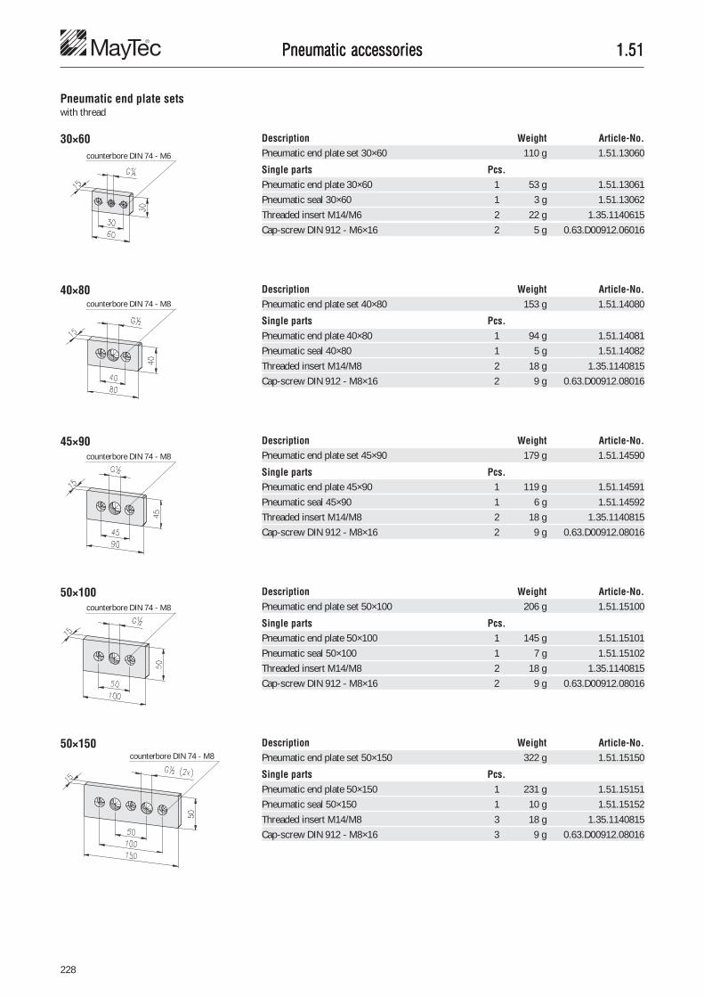
228
1.511.511.511.511.51
Description Weight Article-No.Pneumatic end plate set 50×150 322 g 1.51.15150
Single parts Pcs.Pneumatic end plate 50×150 1 231 g 1.51.15151Pneumatic seal 50×150 1 10 g 1.51.15152Threaded insert M14/M8 3 18 g 1.35.1140815Cap-screw DIN 912 - M8×16 3 9 g 0.63.D00912.08016
50×150counterbore DIN 74 - M8
Pneumatic accessoriesPneumatic accessoriesPneumatic accessoriesPneumatic accessoriesPneumatic accessories
Description Weight Article-No.Pneumatic end plate set 30×60 110 g 1.51.13060
Single parts Pcs.Pneumatic end plate 30×60 1 53 g 1.51.13061Pneumatic seal 30×60 1 3 g 1.51.13062Threaded insert M14/M6 2 22 g 1.35.1140615Cap-screw DIN 912 - M6×16 2 5 g 0.63.D00912.06016
Description Weight Article-No.Pneumatic end plate set 40×80 153 g 1.51.14080
Single parts Pcs.Pneumatic end plate 40×80 1 94 g 1.51.14081Pneumatic seal 40×80 1 5 g 1.51.14082Threaded insert M14/M8 2 18 g 1.35.1140815Cap-screw DIN 912 - M8×16 2 9 g 0.63.D00912.08016
Description Weight Article-No.Pneumatic end plate set 45×90 179 g 1.51.14590
Single parts Pcs.Pneumatic end plate 45×90 1 119 g 1.51.14591Pneumatic seal 45×90 1 6 g 1.51.14592Threaded insert M14/M8 2 18 g 1.35.1140815Cap-screw DIN 912 - M8×16 2 9 g 0.63.D00912.08016
Description Weight Article-No.Pneumatic end plate set 50×100 206 g 1.51.15100
Single parts Pcs.Pneumatic end plate 50×100 1 145 g 1.51.15101Pneumatic seal 50×100 1 7 g 1.51.15102Threaded insert M14/M8 2 18 g 1.35.1140815Cap-screw DIN 912 - M8×16 2 9 g 0.63.D00912.08016
30×60
40×80
45×90
50×100
counterbore DIN 74 - M8
counterbore DIN 74 - M6
counterbore DIN 74 - M8
counterbore DIN 74 - M8
Pneumatic end plate setswith thread

229
5
1.511.511.511.511.51Pneumatic accessoriesPneumatic accessoriesPneumatic accessoriesPneumatic accessoriesPneumatic accessories
Description Weight Article-No.Pneumatic end plate set 80×80 W 271 g 1.51.18080W
Single parts Pcs.Pneumatic end plate 80×80 W 1 182 g 1.51.18081WPneumatic seal 80×80 W 1 8 g 1.51.18082WThreaded insert M14/M8 3 18 g 1.35.1140815Cap-screw DIN 912 - M8×16 3 9 g 0.63.D00912.08016
Description Weight Article-No.Pneumatic end plate set 60×90 217 g 1.51.16090
Single parts Pcs.Pneumatic end plate 60×90 1 156 g 1.51.16091Pneumatic seal 60×90 1 7 g 1.51.16092Threaded insert M14/M8 2 18 g 1.35.1140815Cap-screw DIN 912 - M8×16 2 9 g 0.63.D00912.08016
Description Weight Article-No.Pneumatic end plate set 80×80 251 g 1.51.18080
Single parts Pcs.Pneumatic end plate 80×80 1 136 g 1.51.18081Pneumatic seal 80×80 1 7 g 1.51.18082Threaded insert M14/M8 4 18 g 1.35.1140815Cap-screw DIN 912 - M8×16 4 9 g 0.63.D00912.08016
Description Weight Article-No.Pneumatic end plate set 100×100 416 g 1.51.20100
Single parts Pcs.Pneumatic end plate 100×100 1 296 g 1.51.20101Pneumatic seal 100×100 1 12 g 1.51.20102Threaded insert M14/M8 4 18 g 1.35.1140815Cap-screw DIN 912 - M8×16 4 9 g 0.63.D00912.08016
80×80 angle
60×90
80×80
100×100counterbore DIN 74 - M8
counterbore DIN 74 - M8
counterbore DIN 74 - M8
counterbore DIN 74 - M8
Pneumatic end plate setswith thread

230
1.521.521.521.521.52Pneumatic accessoriesPneumatic accessoriesPneumatic accessoriesPneumatic accessoriesPneumatic accessories
Pneumatic connection platesPneumatic connection platesPneumatic connection platesPneumatic connection platesPneumatic connection plates ApplicationPneumatic connection for inlet and exhaustof air pressure
CommentsCounterbore DIN 74 - M6 / M8 forcap-screw DIN 912 - M6 / M8
30×60
40×80
45×90
50×100 Description Weight Article-No.Pneumatic connection plate set 50×100 90.6 g 1.52.15101
Single parts Pcs.Pneumatic connection plate 50×100 1 60.0 g 1.52.15102O-Ring 20×3 1 0.6 g 1.59.12003T-Nut for subs. insertion E, M6 2 10.0 g 1.32.4EM6Cap-screw DIN 912 - M6×16 2 5.0 g 0.63.D00912.06016
Description Weight Article-No.Pneumatic connection plate set 30×60 59.2 g 1.52.03061
Single parts Pcs.Pneumatic connection plate 30×60 1 40.0 g 1.52.03062O-Ring 14×3 1 0.6 g 1.59.11403T-Nut for subs. insertion F, M6 2 4.3 g 1.32.4FM6Cap-screw DIN 912 - M6×12 2 5.0 g 0.63.D00912.06012
Description Weight Article-No.Pneumatic connection plate set 40×80 80.6 g 1.52.14081
Single parts Pcs.Pneumatic connection plate 40×80 1 50.0 g 1.52.14082O-Ring 20×3 1 0.6 g 1.59.12003T-Nut for subs. insertion E, M6 2 10.0 g 1.32.4EM6Cap-screw DIN 912 - M6×16 2 5.0 g 0.63.D00912.06016
Description Weight Article-No.Pneumatic connection plate set 45×90 84.6 g 1.52.04591
Single parts Pcs.Pneumatic connection plate 45×90 1 5.0 g 1.52.04592O-Ring 20×3 1 0.6 g 1.59.12003T-Nut for subs. insertion E, M6 2 10.0 g 1.32.4EM6Cap-screw DIN 912 - M6×16 2 5.0 g 0.63.D00912.06016
counterbore DIN 74 - M6
counterbore DIN 74 - M6
counterbore DIN 74 - M6
counterbore DIN 74 - M6
Technical dataEnd plate• material: aluminium• strength: F22• surface: black powder-coatedO-Ring• material: NBR

231
5
1.541.541.541.541.54Pneumatic accessoriesPneumatic accessoriesPneumatic accessoriesPneumatic accessoriesPneumatic accessories
Pneumatic extension setsPneumatic extension setsPneumatic extension setsPneumatic extension setsPneumatic extension sets
For the extension of air pressurised profiles
for profile 100×100
Description Pcs. Weight Article-No.Pneumatic extension set 30×60 177 g 1.54.03061Single partsPneumatic seal 30×60 1 3 g 1.51.13062Connector, profile extension 2 87 g 1.21.3V0
Pneumatic extension set 40×80 193 g 1.54.04081Single partsPneumatic seal 40×80 1 5 g 1.51.14082Connector, profile extension 2 94 g 1.21.4V0
Pneumatic extension set 45×90 204 g 1.54.04591Single partsPneumatic seal 45×90 1 6 g 1.51.14592Connector, profile extension 2 99 g 1.21.45V0
Pneumatic extension set 50×100 211 g 1.54.05101Single partsPneumatic seal 50×100 1 7 g 1.51.15102Connector, profile extension 2 102 g 1.21.5V0
Pneumatic extension set 50×150 316 g 1.54.05151Single partsPneumatic seal 50×150 1 10 g 1.51.15152Connector, profile extension 3 102 g 1.21.5V0
Pneumatic extension set 60×90 239 g 1.54.06091Single partsPneumatic seal 60×90 1 7 g 1.51.16092Connector, profile extension 2 116 g 1.21.6V0
Pneumatic extension set 80×80 W 289 g 1.54.08081WSingle partsPneumatic seal 80×80 W 1 7 g 1.51.18082WConnector, profile extension 3 94g 1.21.4V0
Pneumatic extension set 100×100 420 g 1.54.10101Single partsPneumatic seal 100×100 1 12 g 1.51.20102Connector, profile extension 4 102 g 1.21.5V0
Pneumatic extension set 80×80 384 g 1.54.08081Single partsPneumatic seal 80×80 1 8 g 1.51.18082Connector, profile extension 4 94 g 1.21.4V0
for profile 30×60
for profile 40×80
for profile 45×90
for profile 50×100
for profile 50×150
for profile 60×90
for profile 80×80 angle
for profile 80×80

232
1.551.551.551.551.55Pneumatic accessoriesPneumatic accessoriesPneumatic accessoriesPneumatic accessoriesPneumatic accessories
Pneumatic 90° connection setsPneumatic 90° connection setsPneumatic 90° connection setsPneumatic 90° connection setsPneumatic 90° connection sets
For 90° connections of air pressurisedprofiles
Description Pcs. Weight Article-No.Pneumatic 90° connection set 30×60 99 g 1.55.03061Single partsPneumatic seal 30×60 1 3 g 1.51.13062Connector, standard 90° 2 48 g 1.21.3F2
Pneumatic 90° connection set 40×80 115 g 1.55.04081Single partsPneumatic seal 40×80 1 5 g 1.51.14082Connector, standard 90° 2 55 g 1.21.4E2
Pneumatic 90° connection set 45×90 63 g 1.55.04591Single partsPneumatic seal 45×90 1 6 g 1.51.14592Connector, standard 90° 2 57 g 1.21.45E2
Pneumatic 90° connection set 50×100 125 g 1.55.05101Single partsPneumatic seal 50×100 1 7 g 1.51.15102Connector, standard 90° 2 59 g 1.21.5E2
Pneumatic 90° connection set 50×150 187 g 1.55.05151Single partsPneumatic seal 50×150 1 10 g 1.51.15152Connector, standard 90° 3 59 g 1.21.5E2
Pneumatic 90° connection set 60×90 70 g 1.55.06091Single partsPneumatic seal 60×90 1 7 g 1.51.16092Connector, standard 90° 2 63 g 1.21.6E2
Pneumatic 90° connection set 80×80 446 g 1.55.08081Single partsPneumatic seal 80×80 1 8 g 1.51.18082Connector, standard 90° 4 55 g 1.21.4E2Pneumatic connecting plate 1 217 g 1.55.08084O-Ring 20×3 1 0.6 g 1.59.12003
For the connection of profile 80×80,100×100 a pneumatic connecting plate mustbe inserted to seal the chamber inside
interface
hole distance
for profile 30×60
for profile 40×80
for profile 45×90
for profile 50×100
for profile 50×150
for profile 60×90
for profile 80×80
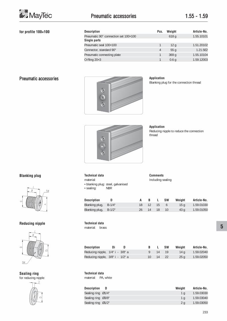
233
5
1.55 - 1.591.55 - 1.591.55 - 1.591.55 - 1.591.55 - 1.59Pneumatic accessoriesPneumatic accessoriesPneumatic accessoriesPneumatic accessoriesPneumatic accessories
Description Pcs. Weight Article-No.Pneumatic 90° connection set 100×100 618 g 1.55.10101Single partsPneumatic seal 100×100 1 12 g 1.51.20102Connector, standard 90° 4 55 g 1.21.5E2Pneumatic connecting plate 1 369 g 1.55.10104O-Ring 20×3 1 0.6 g 1.59.12003
for profile 100×100
Pneumatic accessoriesPneumatic accessoriesPneumatic accessoriesPneumatic accessoriesPneumatic accessories ApplicationBlanking plug for the connection thread
ApplicationReducing nipple to reduce the connectionthread
Blanking plug
Reducing nipple
Sealing ringfor reducing nipple
Technical datamaterial:• blanking plug: steel, galvanised• sealing: NBR
Technical datamaterial: brass
Technical datamaterial: PA, white
Description D A B L SW Weight Article-No.Blanking plug, B-1/4“ 18 12 15 6 15 g 1.59.01030Blanking plug, B-1/2“ 26 14 18 10 43 g 1.59.01050
Description Di D B L SW Weight Article-No.Reducing nipple, 1/4“ i - 3/8“ a 9 14 19 14 g 1.59.02040Reducing nipple, 3/8“ i - 1/2“ a 10 14 22 25 g 1.59.02050
Description D Weight Article-No.Sealing ring Ø1/4“ 1 g 1.59.03030Sealing ring Ø3/8“ 1 g 1.59.03040Sealing ring Ø1/2“ 2 g 1.59.03050
CommentsIncluding sealing

234
1.611.611.611.611.61Additional accessoriesAdditional accessoriesAdditional accessoriesAdditional accessoriesAdditional accessories
Handles light PHandles light PHandles light PHandles light PHandles light PAAAAA ApplicationFor doors and drawers of light material
Description Colour Weight Article-No.Handle light PA grey 30 g 1.61.20.1Handle light PA black 30 g 1.61.20.2
Description Weight Article-No.Handle light Alu 85 g 1.61.210
Handle light AluHandle light AluHandle light AluHandle light AluHandle light Alu ApplicationFor doors and drawers of light material
Mounting on panelelements
Mounting onprofiles
Technical datamaterial: PA
Mounting on panelelements
Mounting onprofiles
Technical datamaterial: aluminiumsurface: natural anodised
countersink DIN 74 - M4
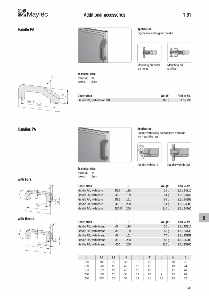
235
6
1.611.611.611.611.61Additional accessoriesAdditional accessoriesAdditional accessoriesAdditional accessoriesAdditional accessories
Description D L Weight Article-No.Handle PA, with bore Ø6.5 110 24 g 1.61.24110Handle PA, with bore Ø6.5 139 44 g 1.61.24139Handle PA, with bore Ø8.5 151 64 g 1.61.24151Handle PA, with bore Ø8.5 200 74 g 1.61.24200Handle PA, with bore Ø10.5 260 114 g 1.61.24260
Description Weight Article-No.Handle PA, with thread M8 166 g 1.61.230
Handle PHandle PHandle PHandle PHandle PAAAAA ApplicationErgonomical designed handle
Mounting on panelelements
Mounting onprofiles
Technical datamaterial: PAcolour: black
Description G L Weight Article-No.Handle PA, with thread M6 110 30 g 1.61.25110Handle PA, with thread M6 139 50 g 1.61.25139Handle PA, with thread M8 151 70 g 1.61.25151Handle PA, with thread M8 200 88 g 1.61.25200Handle PA, with thread M10 260 125 g 1.61.25260
Handles PHandles PHandles PHandles PHandles PAAAAA ApplicationHandle with fixing possibilities from thefront and the rear
Handle with bore Handle with threadTechnical datamaterial: PAcolour: black
L L1 L2 H h T t t1 B
110 94 17 37 8 13 6 10 21139 120 20 40 10 15 6 10 24151 132 22 43 10 16 6 15 26200 180 25 50 11 20 9 15 28260 235 28 53 12 21 11 15 32
with thread
with bore

236
1.611.611.611.611.61Additional accessoriesAdditional accessoriesAdditional accessoriesAdditional accessoriesAdditional accessories
Handle systemHandle systemHandle systemHandle systemHandle systemround design
ApplicationHandle system for making handles of anylength
Mounting on panel elements
Technical datamaterial: PA-GFcolour: black
Corner piece PA-GF
Mounting on profiles
Description Weight Article-No.Corner piece PA-GF 76 g 1.61.280
Description Weight Article-No.Centre piece PA-GF 53 g 1.61.281
Technical datamaterial: PA-GFcolour: black
Description Weight Article-No.Tube Ø30×3 bar 4.2 kg 1.19.16130.60Tube Ø30×3 cut to length 0.7 kg/m 1.19.16130-A00A00/...
/... = length in mm
Centre piece PA-GF
Tube Ø30×3 Technical datamaterial: aluminiumsurface: natural anodisedtube length: 6 m

237
6
1.611.611.611.611.61Additional accessoriesAdditional accessoriesAdditional accessoriesAdditional accessoriesAdditional accessories
Handle systemHandle systemHandle systemHandle systemHandle systemoval design
ApplicationHandle system for making handles of anylength
Mounting on panel elements
Technical datamaterial: PA-GFcolour: black
Oval corner piece right
Mounting on profiles
Description Weight Article-No.Oval corner piece right 65 g 1.61.290
Description Weight Article-No.Oval corner piece left 65 g 1.61.291
Technical datamaterial: PA-GFcolour: black
Description Weight Article-No.Oval tube 35×4 bar 2.5 kg 1.61.292.30Oval tube 35×4 cut to length 0.83 kg/m 1.61.292-A00A00/...
/... = length in mm
Oval corner piece left
Oval tube 35×4 Technical datamaterial: aluminiumsurface: natural anodisedtube length: 3 m

238
1.611.611.611.611.61Additional accessoriesAdditional accessoriesAdditional accessoriesAdditional accessoriesAdditional accessories
Grab handlesGrab handlesGrab handlesGrab handlesGrab handles ApplicationAlu grip handles for customer's assemblyfrom standard profiles
Fixing of the profile directly on the panelelement
Profile 20×30, 1F, LP
CommentsGrab handles increase the rigidity of panelswithout profile frames
Fixing of the profile with a connecting pieceon the panel element
Description Weight Article-No.Profile 20×30, 1F, LP cut to length 0.66 kg/m 1.11.020030.14LP-A00A00/...
/... = length in mm
Grab handle profiles
Description Weight Article-No.Grab handle profile cut to length 0.3 kg/m 1.19.14319-A00A00/...
/... = length in mm
Description Weight Article-No.Grab handle profile cut to length 0.73 kg/m 1.19.14330-A00A00/...
/... = length in mm
Description Weight Article-No.Cover cap kit left/right for grab handle profile 3.6 g 1.19.14330A
Technical datamaterial: PA-GFcolour: black

239
6
1.621.621.621.621.62Additional accessoriesAdditional accessoriesAdditional accessoriesAdditional accessoriesAdditional accessories
HingesHingesHingesHingesHinges
Description Weight Article-No.Hinge 20×32 6 g 1.62.12032
Description Weight Article-No.Hinge 30×39 7.6 g 1.62.23039
Description Weight Article-No.Hinge 40×40 55 g 1.62.24040
ApplicationHinge for doors and flaps of light material
Face-sided connectionof 2 profiles
Connection of 2 profilesin rectangular position
CommentsCountersink DIN 74 - M5 forcountersunk screw DIN 7991 - M5
Doors with profile frames Doors made of panel elements withoutprofile frames
CommentsCountersink DIN 74 - M4 forcountersunk screw DIN 7991 - M4
CommentsCountersink DIN 74 - M5 forcountersunk screw DIN 7991 - M5
Technical data
Hinge 20×32 30×39 40×40
material: PA-GF PA-GF GD-Zn, coated
colour: black
max. static load: 50 N 100 N 150 N
Swivel angle
Swivel angle
Swivel angle
countersinkDIN 74 - M5
countersinkDIN 74 - M4
countersinkDIN 74 - M5

240
1.621.621.621.621.62
�
��
Additional accessoriesAdditional accessoriesAdditional accessoriesAdditional accessoriesAdditional accessories
Lift-off hingesLift-off hingesLift-off hingesLift-off hingesLift-off hinges ApplicationEnables the connection of different profilewidths in parallel as well as in rectangulararrangement
Non-liftable door with one right- and oneleft-sided hinge
left
right
1 profile 30×301 profile 50×50
1 profile 40×401 profile 50×50
1 profile 45×451 profile 50×50
2 profiles 50×50
Liftable door with two similar hinges
Swivel angle Application of locking device:� for panel element� for profile slot, horizontal� for profile slot, vertical
Technical datamaterial: GD-Znsurface: black coatedhinge bolt: stainless steelmax. static load: 250 N
CommentsCountersink DIN 74 - M6 forcountersunk screw DIN 7991 - M6
left
left

241
6
1.621.621.621.621.62
Description A B Weight Article-No.Hinge 31, A16.5 left 59 68 g 1.62.331.16/16LHinge 31, A19.0 left 64 72 g 1.62.331.19/19LHinge 31, A21.5 left 69 76 g 1.62.331.21/21LHinge 31, A24.0 left 74 81 g 1.62.331.24/24LHinge 31, A26.5 left 79 86 g 1.62.331.26/26L
Description Weight Article-No.Anti-twist device for panel element 4 g 1.62.331x2
Description Weight Article-No.Anti-twist device for slot 8 mm 4 g 1.62.331x1
Description A B Weight Article-No.Hinge 31, A16.5 right 59 68 g 1.62.331.16/16RHinge 31, A19.0 right 64 72 g 1.62.331.19/19RHinge 31, A21.5 right 69 76 g 1.62.331.21/21RHinge 31, A24.0 right 74 81 g 1.62.331.24/24RHinge 31, A26.5 right 79 86 g 1.62.331.26/26R
CombinationsDescription A1) A11) Article-No.Hinge 31 × ��/�� left 1.62.331.��/��L1) Data without decimal places
CombinationsDescription A1) A11) Article-No.Hinge 31 × ��/�� right 1.62.331.��/��R1) Data without decimal places
Technical datamaterial: GD-Znsurface: bare
Technical datamaterial: GD-Znsurface: bare
countersinkDIN 74 - M6
Additional accessoriesAdditional accessoriesAdditional accessoriesAdditional accessoriesAdditional accessories
countersinkDIN 74 - M6

242
1.621.621.621.621.62Additional accessoriesAdditional accessoriesAdditional accessoriesAdditional accessoriesAdditional accessories
Lift-off hingesLift-off hingesLift-off hingesLift-off hingesLift-off hinges ApplicationThe hinges enable the connection of profileswith different widths
Non-liftable door with one right- and oneleft-sided hinge
1 profile 60×601 profile 30×30
1 profile 60×601 profile 40×40
1 profile 60×601 profile 45×45
1 profile 60×601 profile 50×50
Liftable door with two similar hinges
Swivel angle
Technical datamaterial: PA-GFsurface: blackhinge bolt: stainless steelmax. static load: 150 N
CommentsCountersink DIN 74 - M6 forcountersunk screw DIN 7991 - M6
left
right
left
left
2 profiles 60×60

243
6
1.621.621.621.621.62Additional accessoriesAdditional accessoriesAdditional accessoriesAdditional accessoriesAdditional accessories
countersinkDIN 74 - M6
Description A = A1 B Weight Article-No.Lift-off hinge 48 A17.5, left 59 8 g 1.62.348.17/17LLift-off hinge 48 A22.5, left 77 10 g 1.62.348.22/22LLift-off hinge 48 A25.0, left 87 15 g 1.62.348.25/25LLift-off hinge 48 A27.5, left 97 25 g 1.62.348.27/27LLift-off hinge 48 A32.5, left 115 35 g 1.62.348.32/32L
Description A = A1 B Weight Article-No.Lift-off hinge 48 A17.5, right 59 8 g 1.62.348.17/17RLift-off hinge 48 A22.5, right 77 10 g 1.62.348.22/22RLift-off hinge 48 A25.0, right 87 15 g 1.62.348.25/25RLift-off hinge 48 A27.5, right 97 25 g 1.62.348.27/27RLift-off hinge 48 A32.5, right 115 35 g 1.62.348.32/32R
CombinationsDescription A1) A11) Article-No.Lift-off hinge 48 × ��/�� left 1.62.348.��/��L1) Data without decimal places
CombinationsDescription A1) A11) Article-No.Lift-off hinge 48 × ��/�� right 1.62.348.��/��R1) Data without decimal places
countersinkDIN 74 - M6

244
1.621.621.621.621.62Additional accessoriesAdditional accessoriesAdditional accessoriesAdditional accessoriesAdditional accessories
HingesHingesHingesHingesHinges ApplicationHinge for doors and flaps of light material
Non-liftable door with one right- and oneleft-sided hinge
Liftable door with two similar hinges
Swivel angle
Technical datamaterial: PA-GFcolour: blackmax. static load: 100 N
CommentsCountersink DIN 74 - M6 forcountersunk screw DIN 7991 - M6
left
right
left
left
Description Weight Article-No.Hinge 32×60 right 21 g 1.62.41R
Description Weight Article-No.Hinge 32×60 left 21 g 1.62.41L
countersinkDIN 74 - M6
countersinkDIN 74 - M6
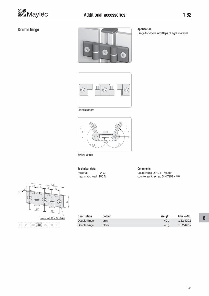
245
6
1.621.621.621.621.62Additional accessoriesAdditional accessoriesAdditional accessoriesAdditional accessoriesAdditional accessories
Double hingeDouble hingeDouble hingeDouble hingeDouble hinge
Description Colour Weight Article-No.Double hinge grey 40 g 1.62.420.1Double hinge black 40 g 1.62.420.2
Technical datamaterial: PA-GFmax. static load: 100 N
CommentsCountersink DIN 74 - M6 forcountersunk screw DIN 7991 - M6
Swivel angle
Liftable doors
ApplicationHinge for doors and flaps of light material
countersink DIN 74 - M6

246
1.621.621.621.621.62
HingesHingesHingesHingesHinges
Additional accessoriesAdditional accessoriesAdditional accessoriesAdditional accessoriesAdditional accessories
1 profile 60×601 profile 30×30
1 profile 60×601 profile 40×40
1 profile 60×601 profile 45×45
1 profile 60×601 profile 50×50
Technical datamaterial: PA-GFcolour: blackhinge bolt: stainless steelmax. static load: 200 N
CommentsCountersink DIN 74 - M6 forcountersunk screw DIN 7991 - M6
2 profiles 60×60
Swivel angle
ApplicationThe hinges enable the connection of profileswith different widths
countersinkDIN 74 - M6
Description A B Weight Article-No.Hinge 48 fixed A17.5 59 8 g 1.62.448.17/17Hinge 48 fixed A22.5 77 10 g 1.62.448.22/22Hinge 48 fixed A25.0 87 15 g 1.62.448.25/25Hinge 48 fixed A27.5 97 25 g 1.62.448.27/27Hinge 48 fixed A32.5 115 35 g 1.62.448.32/32
CombinationsDescription A1) A11) Article-No.Hinge 48 fixed × ��/�� 1.62.448.��/��1) Data without decimal places

247
6
1.621.621.621.621.62
HingeHingeHingeHingeHinge30×60
Additional accessoriesAdditional accessoriesAdditional accessoriesAdditional accessoriesAdditional accessories
Swivel angle
Connection of 2 horizontalprofiles, with anti-twistsafety device
Face-sided connection of 2profiles, with anti-twistsafety device
Connection of 2 verticalprofiles, all anti-twist safetydevices removed
Technical datamaterial: GD-Zncolour: blacksurface: coatedmax. static load: 400 N
ApplicationHinge or higher loads such as doors withprofile frames
Description Weight Article-No.Hinge 30×60 68.8 g 1.62.51030060
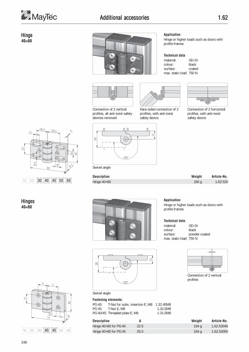
248
1.621.621.621.621.62
HingeHingeHingeHingeHinge40×80
HingesHingesHingesHingesHinges40×80
Additional accessoriesAdditional accessoriesAdditional accessoriesAdditional accessoriesAdditional accessories
Swivel angle
Connection of 2 horizontalprofiles, with anti-twistsafety device
Face-sided connection of 2profiles, with anti-twistsafety device
Connection of 2 verticalprofiles, all anti-twist safetydevices removed
Technical datamaterial: GD-Zncolour: blacksurface: coatedmax. static load: 750 N
ApplicationHinge or higher loads such as doors withprofile frames
Description Weight Article-No.Hinge 40×80 180 g 1.62.520
Description A Weight Article-No.Hinge 40×80 for PG 40 22.5 194 g 1.62.53045Hinge 40×80 for PG 45 25.0 194 g 1.62.53050
Technical datamaterial: GD-Zncolour: blacksurface: powder-coatedmax. static load: 750 N
ApplicationHinge or higher loads such as doors withprofile frames
Swivel angle
Connection of 2 verticalprofiles
Fastening elements:PG 40: T-Nut for subs. insertion E, M8 1.32.4EM8PG 45: T-Nut E, M8 1.32.EM8PG 40/45: Threaded plate E, M8 1.31.EM8

249
6
1.621.621.621.621.62
HingesHingesHingesHingesHinges
Additional accessoriesAdditional accessoriesAdditional accessoriesAdditional accessoriesAdditional accessories
Technical datamaterial: GD-Znsurface: coatedcolour: blackmax. static load: 250 N
CommentsCountersink DIN 74 - M6 forcountersunk screw DIN 7991 - M6
Distances for positioning plugs
ApplicationHinge with detachable fixing plug fordifferent slot distances
Doors with profile frames Swivel angle
Delivery unitIncluding 4 plugs for F- and E-slot
View A
Possibilities of fastening LegendLW = widthG = threaded plate 1.31.���T = T-Nut 1.32.4��
short flange
slots
F E3 E4
B LW G T G T G T
16.5 11 - - x - x x17.5 14.75 x x x - x x18.5 20.5 x x x x x x19 25.25 x x x x x x20 30 x x x x x x
long flange
slots
F E3 E4
C LW G T G T G T
21 11 - - x - x x21.5 30 x x x x x x23.5 19 x x x - x x26 30 x x x x x x27.5 11 - - x - x x31 30 x x x x x x

250
1.621.621.621.621.62Additional accessoriesAdditional accessoriesAdditional accessoriesAdditional accessoriesAdditional accessories
Hinge 50×56
Hinge 50×68
Hinge 50×80
Description Weight Article-No.Hinge 50×56 112 g 1.62.65056
Description Weight Article-No.Hinge 50×68 130 g 1.62.65068
Description Weight Article-No.Hinge 50×80 130 g 1.62.65080
Rear view: plug assignment
Rear view: plug assignment
Rear view: plug assignment
B
16.517.518.51920
2 short flanges
B C
16.5 2117.5 21.518.5 23.519 2620 27.5
31
1 short flange, 1 long flange
2 long flanges
C
2121.523.52627.531
countersinkDIN 74 - M6
countersinkDIN 74 - M6
countersinkDIN 74 - M6

251
6
1.621.621.621.621.62
Alu hingesAlu hingesAlu hingesAlu hingesAlu hinges
Additional accessoriesAdditional accessoriesAdditional accessoriesAdditional accessoriesAdditional accessories
Technical datamaterial: aluminium Al Mg Si 0.5strength: F 25surface: natural anodisedmax. static load: 100 N
CommentsCountersink DIN 74 - M4 forcountersunk screw DIN 7991 - M4
ApplicationFor doors of light material with or withoutprofile frame, each hinge element can becombined
Distance of drill holes for panel elements ofacrylic glass
Connection:• profile to profile• leg built-in
covered• hinge elements:
Type AType A
Type A
1 profile 20×301 profile 50×50
1 profile 30×301 profile 50×50
1 profile 40×401 profile 50×50
2 profiles 50×50
Description T a b Weight Article-No.Hinge element Type A, PG 20, F 1.5 15.3 21 10 g 1.62.7120Hinge element Type A, PG 30 1.5 20.3 29 11 g 1.62.7130Hinge element Type A, PG 30 3.0 20.3 29 15 g 1.62.7130.030Hinge element Type A, PG 40 1.5 25.3 37 13 g 1.62.7140Hinge element Type A, PG 40 3.0 25.3 37 19 g 1.62.7140.030Hinge element Type A, PG 50 1.5 30.3 45 14 g 1.62.7150Hinge element Type A, PG 50 3.0 30.3 45 21 g 1.62.7150.030
Description T a b Weight Article-No.Hinge element Type B, PG 20 2.0 15.3 21 11 g 1.62.7220Hinge element Type B, PG 20 3.0 15.3 21 13 g 1.62.7220.030Hinge element Type B, PG 30 2.0 20.3 29 11 g 1.62.7230Hinge element Type B, PG 30 3.0 20.3 29 13 g 1.62.7230.030Hinge element Type B, PG 40 2.0 25.3 37 13 g 1.62.7240Hinge element Type B, PG 40 3.0 25.3 37 16 g 1.62.7240.030Hinge element Type B, PG 50 2.0 30.3 45 14 g 1.62.7250Hinge element Type B, PG 50 3.0 30.3 45 18 g 1.62.7250.030
Type B Connection:• profile to panel
element• leg one side
visible• hinge elements:
Type AType B
profile 20×30 profile 30×30 profile 40×40 profile 50×50
countersinkDIN 74 - M4
countersinkDIN 74 - M4
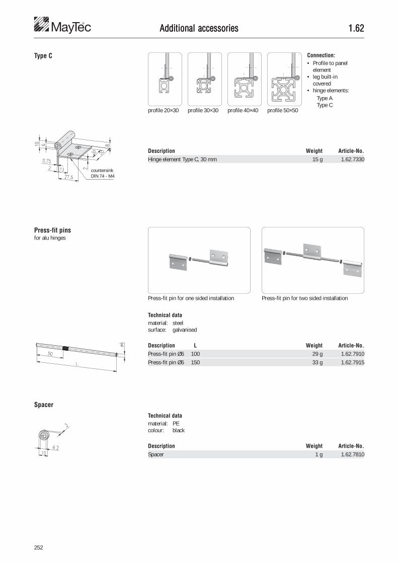
252
1.621.621.621.621.62Additional accessoriesAdditional accessoriesAdditional accessoriesAdditional accessoriesAdditional accessories
Type C Connection:• Profile to panel
element• leg built-in
covered• hinge elements:
Type AType C
profile 20×30 profile 30×30 profile 40×40 profile 50×50
countersinkDIN 74 - M4
Description Weight Article-No.Hinge element Type C, 30 mm 15 g 1.62.7330
Press-fit pinsfor alu hinges
Press-fit pin for one sided installation Press-fit pin for two sided installation
Technical datamaterial: steelsurface: galvanised
Description L Weight Article-No.Press-fit pin Ø6 100 29 g 1.62.7910Press-fit pin Ø6 150 33 g 1.62.7915
Spacer
Description Weight Article-No.Spacer 1 g 1.62.7810
Technical datamaterial: PEcolour: black

253
6
1.621.621.621.621.62
Alu hinges, heavyAlu hinges, heavyAlu hinges, heavyAlu hinges, heavyAlu hinges, heavy
Additional accessoriesAdditional accessoriesAdditional accessoriesAdditional accessoriesAdditional accessories
ApplicationHinge for higher loads such as doors withprofile frames
Application: Type 21, 22, 23, 31with profiles PG 40/50
Application: Type 21, 22, 23, 31with profiles PG 60
Technical datahinge material: aluminium
strength: F25surface: natural anodised
bolt material: steelstainless steel
CommentsCountersink DIN 74 - M8 forcountersunk screw DIN 7991 - M8
Application: Type 21, 22, 23, 31with profiles PG 30/40/50
Swivel angle: Type 21, 22, 23, 31at application with profiles PG 30/40/50
Swivel angle: Type 21, 22, 23, 31at application with profiles PG 60
PG A B
30 27 2840 32 3350 37 38
Swivel angle: Type 20Application: Type 20
PG A
30 2740 3250 37

254
1.621.621.621.621.62Additional accessoriesAdditional accessoriesAdditional accessoriesAdditional accessoriesAdditional accessories
Description Bolt A B Weight Article-No.Alu hinge, heavy, type 21, PG 30/30-50 steel 27 89 123 g 1.62.842127085Alu hinge, heavy, type 21, PG 40/40-50 steel 32 100 159 g 1.62.842132085Alu hinge, heavy, type 21, PG 50 steel 37 100 159 g 1.62.842137085
Alu hinge, heavy, type 21, PG 30/30-50 stainless 27 89 123 g 1.62.842127085VAlu hinge, heavy, type 21, PG 40/40-50 stainless 32 100 159 g 1.62.842132085VAlu hinge, heavy, type 21, PG 50 stainless 37 100 159 g 1.62.842137085V
Description Bolt A Weight Article-No.Alu hinge, heavy, type 23, PG 40/40-50 steel 32 258 g 1.62.842332085Alu hinge, heavy, type 23, PG 50 steel 37 258 g 1.62.842337085
Alu hinge, heavy, type 23, PG 40/40-50 stainless 32 258 g 1.62.842332085VAlu hinge, heavy, type 23, PG 50 stainless 37 258 g 1.62.842337085V
Description Bolt A Weight Article-No.Alu hinge, heavy, type 22, PG 40/40-50 steel 32 261 g 1.62.842232085Alu hinge, heavy, type 22, PG 50 steel 37 261 g 1.62.842237085
Alu hinge, heavy, type 22, PG 40/40-50 stainless 32 261 g 1.62.842232085VAlu hinge, heavy, type 22, PG 50 stainless 37 261 g 1.62.842237085V
Description Bolt A Weight Article-No.Alu hinge, heavy, type 31, PG 40/40-50 steel 32 245 g 1.62.843132128Alu hinge, heavy, type 31, PG 50 steel 37 245 g 1.62.843137128
Alu hinge, heavy, type 31, PG 40/40-50 stainless 32 245 g 1.62.843132128VAlu hinge, heavy, type 31, PG 50 stainless 37 245 g 1.62.843137128V
countersink DIN 74 - M8
countersink DIN 74 - M8
countersink DIN 74 - M8
countersink DIN 74 - M8
Description Bolt A B Weight Article-No.Alu hinge, heavy, type 20, PG 30 steel 27 78 130 g 1.62.842027085Alu hinge, heavy, type 20, PG 40 steel 32 100 166 g 1.62.842032085Alu hinge, heavy, type 20, PG 50 steel 37 100 166 g 1.62.842037085
Alu hinge, heavy, type 20, PG 30 stainless 27 78 130 g 1.62.842027085VAlu hinge, heavy, type 20, PG 40 stainless 32 100 166 g 1.62.842032085VAlu hinge, heavy, type 20, PG 50 stainless 37 100 166 g 1.62.842037085V
countersink DIN 74 - M8

255
6
1.631.631.631.631.63Additional accessoriesAdditional accessoriesAdditional accessoriesAdditional accessoriesAdditional accessories
JointsJointsJointsJointsJointswith / without clamping lever
ApplicationTo enable infinitely variable adjusting andswivelling of profiles
Mounting on profile side
Mounting on profile end
max. loads
Joint F1max F2max
20×20 10 Nm 2,000 N30×30 30 Nm 4,000 N30×50 50 Nm 4,000 N30×100 100 Nm 8,000 N30×100 1) 200 Nm 8,000 N40×40 50 Nm 6,000 N50×50 60 Nm 10,000 N
The MayTec clamping system allowsbacklash free adjusting and clamping
The joint can be locked with the adjustableclamping lever
Technical datamaterial: steelsurface: galvanised
Mounting on profile side
Mounting on profile end
CommentsMounting with:• cap-screw DIN 6912• washer DIN 433
1) with fastening plate
Dimensions of clamping lever for joint:
20×20
Dimensions of clamping lever for joints:
30×3030×50
30×10040×4050×50

256
1.631.631.631.631.63Additional accessoriesAdditional accessoriesAdditional accessoriesAdditional accessoriesAdditional accessories
Description G L Weight Article-No.Joint 50×50 M8 7.5 1,244 g 1.63.05051Joint 50×50 with clamping lever M8 7.5 1,300 g 1.63.15051Anti-twist device for joint, L50 33 g 1.63.03052
Description G L Weight Article-No.Joint 40×40 M8 7.5 674 g 1.63.04041Joint 40×40 with clamping lever M8 7.5 739 g 1.63.14041Anti-twist device for joint, L40 28 g 1.63.04042
Description G L Weight Article-No.Joint 30×100 M8 7.5 1,098 g 1.63.03101Joint 30×100 with clamping lever M8 7.5 1,160 g 1.63.13101
Description G L Weight Article-No.Joint 30×50 M8 7.5 533 g 1.63.03051Joint 30×50 with clamping lever M8 7.5 600 g 1.63.13051Anti-twist device for joint, L30 28 g 1.63.03032Anti-twist device for joint, L50 33 g 1.63.03052
Description G L Weight Article-No.Joint 30×30 M6 7.5 315 g 1.63.03031Joint 30×30 with clamping lever M6 7.5 380 g 1.63.13031Anti-twist device for joint, L30 28 g 1.63.03032
30×30
30×50
30×100
40×40
50×50
CommentsTo increase the load capacity on hinge 30×100� fastening plate 30×150, 1.47.60315
20×20
Description G L Weight Article-No.Joint 20×20 M5 6.5 97 g 1.63.02021Joint 20×20 with clamping lever M5 6.5 114 g 1.63.12021Anti-twist device for joint, H, L20 8 g 1.63.02022Anti-twist device for joint, F, L20 8 g 1.63.02023

257
6
1.631.631.631.631.63
Description G L Weight Article-No.Joint Zn 40×40 M8 9.0 300 g 1.63.51040040Joint Zn 40×40 with clamping lever M8 9.0 344 g 1.63.52040040
40×40
Additional accessoriesAdditional accessoriesAdditional accessoriesAdditional accessoriesAdditional accessories
Joints ZnJoints ZnJoints ZnJoints ZnJoints Znwith / without clamping lever
ApplicationTo enable infinitely variable adjusting andswivelling of profiles
Mounting on profile side
max. loads
Joint F1max F2max
30×30 500 N 500 N40×40 750 N 750 N45×45 750 N 750 N
The MayTec clamping system allowsbacklash free adjusting and clamping
The joint can be locked with the adjustableclamping lever
Technical datamaterial: GD-Znsurface: aluminium coloured
powder-coated
Mounting on profile end
CommentsMounting with:• cap screw DIN 6912• washer DIN 433
Description G L Weight Article-No.Joint Zn 30×30 M8 7.0 124 g 1.63.51030030Joint Zn 30×30 with clamping lever M8 7.0 147 g 1.63.52030030
30×30
Description G L Weight Article-No.Joint Zn 45×45 M8 8.0 320 g 1.63.51045045Joint Zn 45×45 with clamping lever M8 8.0 366 g 1.63.52045045
45×45

258
1.641.641.641.641.64Additional accessoriesAdditional accessoriesAdditional accessoriesAdditional accessoriesAdditional accessories
Mounting blocksMounting blocksMounting blocksMounting blocksMounting blocksscrew-type
Mounting on the profile with threaded plateor T-Nut
Adjustable position
ApplicationFor mounting of panels
Description G Colour Weight Article-No.Mounting block screw type M3 grey 9 g 1.64.10M3.1Mounting block screw type M3 black 9 g 1.64.10M3.2Mounting block screw type M4 grey 9 g 1.64.10M4.1Mounting block screw type M4 black 9 g 1.64.10M4.2Mounting block screw type M5 grey 9 g 1.64.10M5.1Mounting block screw type M5 black 9 g 1.64.10M5.2Mounting block screw type M6 grey 9 g 1.64.10M6.1Mounting block screw type M6 black 9 g 1.64.10M6.2
CommentsA 'floating' nut allows additional tolerance inthe panel mounting holes.
Technical dataMounting blockmaterial: PA-GFcolours: grey, blackThreaded platematerial: steelsurface: galvanised
washerA6,4 DIN 125

259
6
1.641.641.641.641.64Additional accessoriesAdditional accessoriesAdditional accessoriesAdditional accessoriesAdditional accessories
Mounting block GD-ZnMounting block GD-ZnMounting block GD-ZnMounting block GD-ZnMounting block GD-Zn ApplicationFor mounting of panels
Description G Surface Weight Article-No.Mounting block GD-Zn M8 natural 68 g 1.64.153030.1Mounting block GD-Zn M8 black 68 g 1.64.153030.2
Technical datamaterial: GD-Zn
Anti-twistable mounting in steps of 1 mm

260
1.641.641.641.641.64Additional accessoriesAdditional accessoriesAdditional accessoriesAdditional accessoriesAdditional accessories
Mounting blocksMounting blocksMounting blocksMounting blocksMounting blocksfor subsequent insertion
ApplicationFor the mounting of panels with subsequentinsertionVariable mounting position of panels withdistancing plate
H-slot Tolerance equa-lisation: 4 mm
Description B Weight Article-No.Distancing plate for mounting block H 1 0.2 g 1.64.xH01Distancing plate for mounting block H 2 0.4 g 1.64.xH02Distancing plate for mounting block H 3 0.6 g 1.64.xH03Distancing plate for mounting block H 4 0.8 g 1.64.xH04
Technical datamaterial: PA-GFcolour: black
Description G Colour Weight Article-No.Mounting block F M4 grey 9 g 1.64.2F2M4.1Mounting block F M4 black 9 g 1.64.2F2M4.2Mounting block F M5 grey 9 g 1.64.2F2M5.1Mounting block F M5 black 9 g 1.64.2F2M5.2Mounting block F M6 grey 9 g 1.64.2F2M6.1Mounting block F M6 black 9 g 1.64.2F2M6.2
F-slot E3-slot E4-slot Tolerance equa-lisation: 9 mm
Technical datamaterial: PA-GFcolours: grey, blacksquare nut: steel , galvanisedmax. static load: 250 N, rectangular to slot
Mounting blocks F and E
Mounting block H
Description G Weight Article-No.Mounting block H M4 2.6 g 1.64.2H2M4.2
Technical datamaterial: PA-GFcolour: blacksquare nut: steel , galvanisedmax. static load: 100 N, rectangular to slot

261
6
1.641.641.641.641.64
Description B Colour Weight Article-No.Distancing plate for mounting block FE 2 grey 0.5 g 1.64.2x02.1Distancing plate for mounting block FE 2 black 0.5 g 1.64.2x02.2Distancing plate for mounting block FE 3 grey 0.8 g 1.64.2x03.1Distancing plate for mounting block FE 3 black 0.8 g 1.64.2x03.2Distancing plate for mounting block FE 5 grey 1.3 g 1.64.2x05.1Distancing plate for mounting block FE 5 black 1.3 g 1.64.2x05.2
Description B Colour Weight Article-No.Distancing plate, thin, for mounting block FE 2 grey 0.3 g 1.64.2x102.1Distancing plate, thin, for mounting block FE 2 black 0.3 g 1.64.2x102.2Distancing plate, thin, for mounting block FE 3 grey 0.6 g 1.64.2x103.1Distancing plate, thin, for mounting block FE 3 black 0.6 g 1.64.2x103.2Distancing plate, thin, for mounting block FE 5 grey 0.9 g 1.64.2x105.1Distancing plate, thin, for mounting block FE 5 black 0.9 g 1.64.2x105.2
Additional accessoriesAdditional accessoriesAdditional accessoriesAdditional accessoriesAdditional accessories
Technical datamaterial: PA-GFcolours: grey, black
Description G Colour a Weight Article-No.Mounting block E3 M4 grey 3.0 10.5 g 1.64.2E3M4.1Mounting block E3 M4 black 3.0 10.5 g 1.64.2E3M4.2Mounting block E3 M5 grey 3.0 10.1 g 1.64.2E3M5.1Mounting block E3 M5 black 3.0 10.1 g 1.64.2E3M5.2Mounting block E3 M6 grey 3.0 9.6 g 1.64.2E3M6.1Mounting block E3 M6 black 3.0 9.6 g 1.64.2E3M6.2
Mounting block E4 M4 grey 4.0 10.6 g 1.64.2E4M4.1Mounting block E4 M4 black 4.0 10.6 g 1.64.2E4M4.2Mounting block E4 M5 grey 4.0 10.2 g 1.64.2E4M5.1Mounting block E4 M5 black 4.0 10.2 g 1.64.2E4M5.2Mounting block E4 M6 grey 4.0 9.9 g 1.64.2E4M6.1Mounting block E4 M6 black 4.0 9.9 g 1.64.2E4M6.2
Mounting blocks E
ApplicationFor the mounting of folded panels
Technical datamaterial: PA-GFcolours: grey, black
Distancing plate, thinDistancing plate, thinDistancing plate, thinDistancing plate, thinDistancing plate, thin
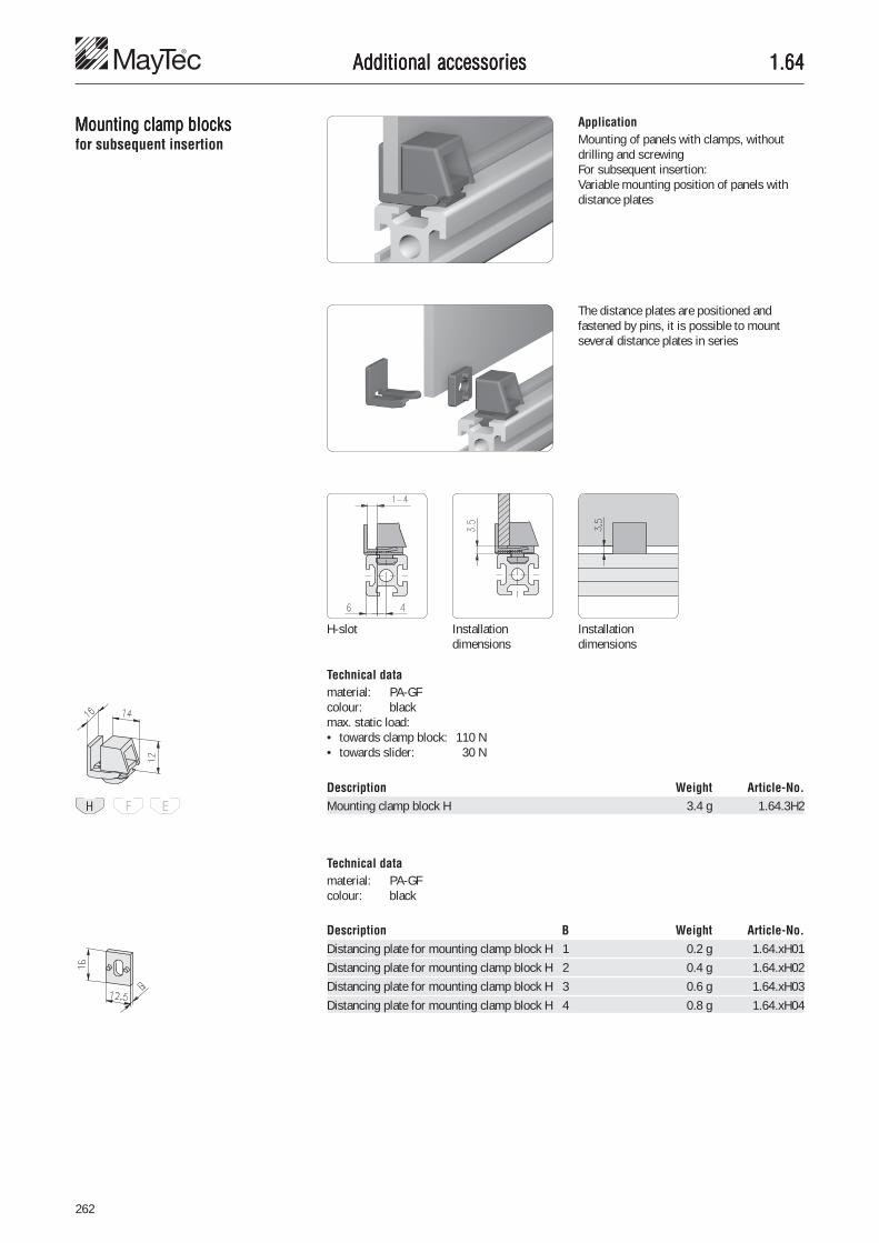
262
1.641.641.641.641.64Additional accessoriesAdditional accessoriesAdditional accessoriesAdditional accessoriesAdditional accessories
Mounting clamp blocksMounting clamp blocksMounting clamp blocksMounting clamp blocksMounting clamp blocksfor subsequent insertion
ApplicationMounting of panels with clamps, withoutdrilling and screwingFor subsequent insertion:Variable mounting position of panels withdistance plates
The distance plates are positioned andfastened by pins, it is possible to mountseveral distance plates in series
H-slot Installationdimensions
Description Weight Article-No.Mounting clamp block H 3.4 g 1.64.3H2
Description B Weight Article-No.Distancing plate for mounting clamp block H 1 0.2 g 1.64.xH01Distancing plate for mounting clamp block H 2 0.4 g 1.64.xH02Distancing plate for mounting clamp block H 3 0.6 g 1.64.xH03Distancing plate for mounting clamp block H 4 0.8 g 1.64.xH04
Technical datamaterial: PA-GFcolour: blackmax. static load:• towards clamp block: 110 N• towards slider: 30 N
Technical datamaterial: PA-GFcolour: black
Installationdimensions
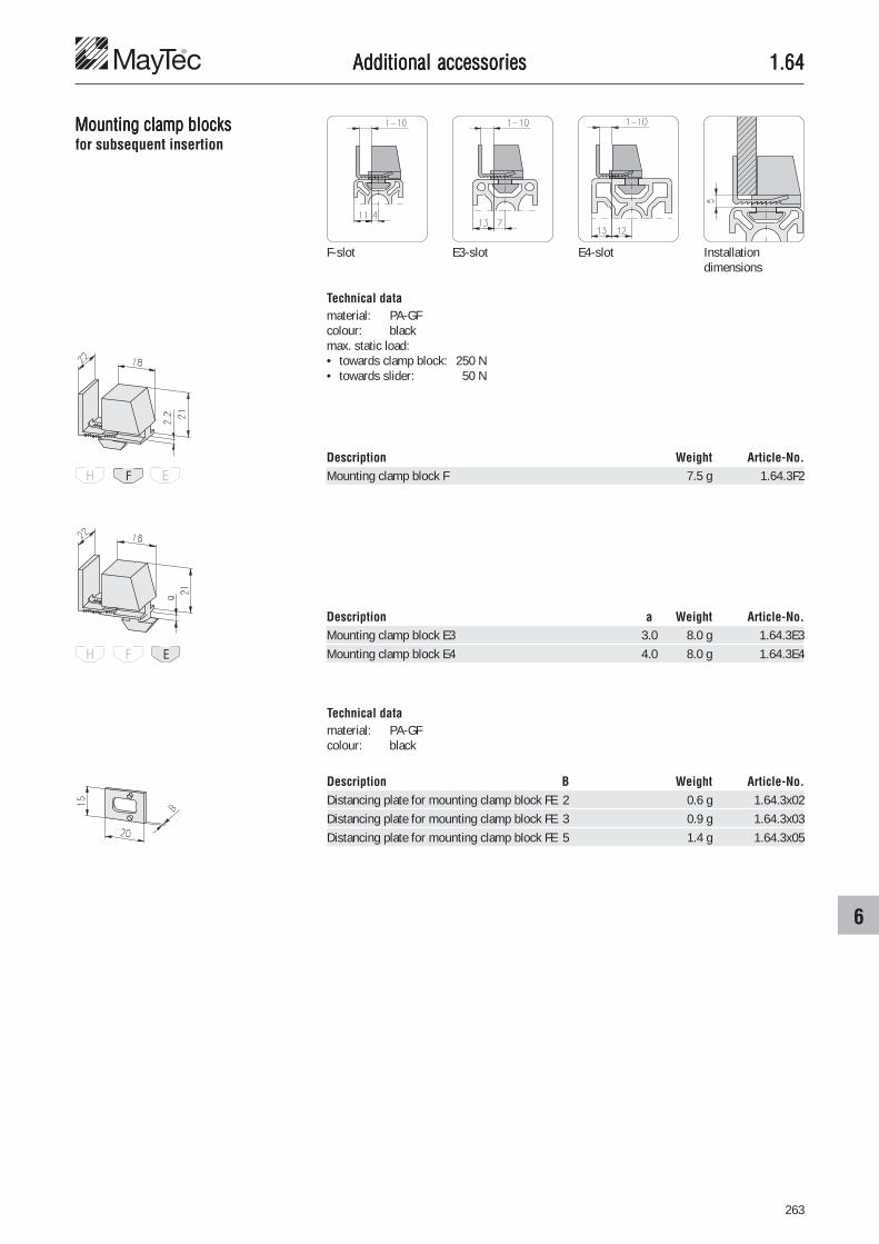
263
6
1.641.641.641.641.64
F-slot E3-slot E4-slot Installationdimensions
Description Weight Article-No.Mounting clamp block F 7.5 g 1.64.3F2
Description B Weight Article-No.Distancing plate for mounting clamp block FE 2 0.6 g 1.64.3x02Distancing plate for mounting clamp block FE 3 0.9 g 1.64.3x03Distancing plate for mounting clamp block FE 5 1.4 g 1.64.3x05
Additional accessoriesAdditional accessoriesAdditional accessoriesAdditional accessoriesAdditional accessories
Mounting clamp blocksMounting clamp blocksMounting clamp blocksMounting clamp blocksMounting clamp blocksfor subsequent insertion
Technical datamaterial: PA-GFcolour: blackmax. static load:• towards clamp block: 250 N• towards slider: 50 N
Technical datamaterial: PA-GFcolour: black
Description a Weight Article-No.Mounting clamp block E3 3.0 8.0 g 1.64.3E3Mounting clamp block E4 4.0 8.0 g 1.64.3E4

264
1.641.641.641.641.64Additional accessoriesAdditional accessoriesAdditional accessoriesAdditional accessoriesAdditional accessories
Mounting clamp blocks SLMounting clamp blocks SLMounting clamp blocks SLMounting clamp blocks SLMounting clamp blocks SLfor subsequent insertion
ApplicationAs mounting clamp block, however:For safety’s sake it is only possible to beopened with special tools
F-slot E3-slot E4-slot Installationdimensions
Description Weight Article-No.Mounting clamp block F, SL 7.5 g 1.64.4F2Mounting clamp block E3, SL 8.0 g 1.64.4E3Mounting clamp block E4, SL 8.0 g 1.64.4E4
Description B Weight Article-No.Distancing plate for mounting clamp block FE 2 0.6 g 1.64.3x02Distancing plate for mounting clamp block FE 3 0.9 g 1.64.3x03Distancing plate for mounting clamp block FE 5 1.4 g 1.64.3x05
Description Weight Article-No.Tool for mounting clamp block SL 23 g 1.64.4W
Technical datamaterial: PA-GFcolour: blackmax. static load:• towards clamp block: 250 N• towards slider: 50 N
Technical datamaterial: PA-GFcolour: redsteel bolt: hardened
Technical datamaterial: PA-GFcolour: black

265
6
1.641.641.641.641.64Additional accessoriesAdditional accessoriesAdditional accessoriesAdditional accessoriesAdditional accessories
Quick locksQuick locksQuick locksQuick locksQuick locks ApplicationMounting element for quick mounting anddismounting of covers
Fastening without washerHmax = Sretaining ring + panel thickness
Commentsopen: by 1/4-turnclose: by push in
Fastening with washerHmax = Sretaining ring + panel thickness + Swasher
Technical data (assembly)drilling diameterin the covers: 7 mmmax. static load: 900 Nlife time: ca. 10.000 operations
Description Weight Article-No.Mounting angle 14 g 1.64.5101
Description S Weight Article-No.Retaining ring 1.7 1.3 g 1.64.5217Retaining ring 2.5 1.8 g 1.64.5225Retaining ring 4.0 3.5 g 1.64.5240Retaining ring 5.0 4.0 g 1.64.5250Retaining ring 6.0 4.5 g 1.64.5260
Retaining rings
Mounting angle Technical datamaterial: steelsurface: galvanised
Technical datamaterial: neoprenehardness: 55 Shore Atemperature range: - 50°C to + 90°C
Mounting elements:F-slot:• T-Nut, with leaf
spring F, 2×M4 1.32.4F2M4.25• threaded plate F, M4 1.31.FM4• spring nut F, M4 1.33.FM4• T-slot nut F, M4 1.34.10FM4E-slot:• T-Nut, with leaf
spring E, 2×M4 1.32.4E2M4.25• spring nut E, M4 1.33.EM4• T-slot nut E, M4 1.34.10EM4• rhomboid T-slot nut E, M4 1.34.20EM4

266
1.641.641.641.641.64Additional accessoriesAdditional accessoriesAdditional accessoriesAdditional accessoriesAdditional accessories
Description Hmax L I Weight Article-No.Round head bolt 3.7 16.6 14.4 4.0 g 1.64.5416Round head bolt 4.7 17.6 15.4 4.0 g 1.64.5417Round head bolt 5.7 18.6 16.4 4.0 g 1.64.5418Round head bolt 6.9 19.8 17.6 4.5 g 1.64.5419Round head bolt 7.7 20.6 18.4 5.0 g 1.64.5420Round head bolt 8.9 21.8 19.6 5.0 g 1.64.5421Round head bolt 9.7 22.6 20.4 6.0 g 1.64.5422Round head bolt 10.7 23.6 21.4 6.0 g 1.64.5423
Description Hmax L I Weight Article-No.Knurled head bolt 3.7 16.6 14.4 14.0 g 1.64.5516Knurled head bolt 4.7 17.6 15.4 14.0 g 1.64.5517Knurled head bolt 5.7 18.6 16.4 14.0 g 1.64.5518Knurled head bolt 6.9 19.8 17.6 14.0 g 1.64.5519Knurled head bolt 7.7 20.6 18.4 15.0 g 1.64.5520Knurled head bolt 8.9 21.8 19.6 15.0 g 1.64.5521Knurled head bolt 10.7 23.6 21.4 15.0 g 1.64.5523
Description Hmax L I Weight Article-No.Wing head bolt 3.7 16.6 14.4 5.8 g 1.64.5616Wing head bolt 4.7 17.6 15.4 5.8 g 1.64.5617Wing head bolt 5.7 18.6 16.4 5.8 g 1.64.5618Wing head bolt 6.9 19.8 17.6 5.8 g 1.64.5619Wing head bolt 7.7 20.6 18.4 6.3 g 1.64.5620Wing head bolt 8.9 21.8 19.6 6.3 g 1.64.5621Wing head bolt 9.7 22.6 20.4 6.3 g 1.64.5622Wing head bolt 10.7 23.6 21.4 6.3 g 1.64.5623
Description S Weight Article-No.Sealing washer 0.5 0.8 g 1.64.5305Sealing washer 1.0 1.7 g 1.64.5310Sealing washer 1.5 2.5 g 1.64.5315Sealing washer 2.0 3.3 g 1.64.5320
Sealing washers
Round head bolts
Knurled head bolts
Wing head bolts
Technical datamaterial: brasssurface: nickel-plated
CommentsMounting dimension "H" see mountingsketch
Technical datamaterial: neoprenehardness: 55 Shore Atemperature range: - 50°C to + 90°C
Technical datamaterial: brasssurface: nickel-plated
CommentsMounting dimension "H" see mountingsketch
Technical datamaterial: brasssurface: nickel-plated
CommentsMounting dimension "H" see mountingsketch

267
6
1.651.651.651.651.65Additional accessoriesAdditional accessoriesAdditional accessoriesAdditional accessoriesAdditional accessories
Bullet catchesBullet catchesBullet catchesBullet catchesBullet catches
Description Weight Article-No.Bullet catch 9×50 25.0 g 1.65.1101
Description Weight Article-No.Bullet catch 12×70 72.0 g 1.65.1102
ApplicationLock for swinging and sliding doors
CommentsCountersink DIN 74 - M4 for countersunkscrew DIN 7991 - M4
Technical datamaterial: brass, naturalbullet: stainless steelretention force: adjustable
CommentsCountersink DIN 74 - M4 for countersunkscrew DIN 7991 - M4
countersinkDIN 74 - M4
countersink
DIN 74 - M4
countersink
DIN 74 - M4
countersinkDIN 74 - M4

268
1.651.651.651.651.65Additional accessoriesAdditional accessoriesAdditional accessoriesAdditional accessoriesAdditional accessories
Bullet catch PBullet catch PBullet catch PBullet catch PBullet catch PAAAAA
Description Weight Article-No.Bullet catch PA 23.0 g 1.65.1201
Description Weight Article-No.Angle 20×47, M8 16.0 g 1.65.1301
ApplicationLock for swinging and sliding doors
Fastening of the bolt withangle 25×40, Ø8.7 � 1.46.115
Fastening of the bolt withangle 20×47, M8 � 1.65.1301
Bullet catch PATechnical datacapsule: PA-GF, blackbolt: steel, galvanisedretention force: 45 N
AngleTechnical datamaterial: aluminiumstrength: F22surface: natural anodised
sphere Ø7

269
6
1.651.651.651.651.65
Magnetic lock PMagnetic lock PMagnetic lock PMagnetic lock PMagnetic lock PAAAAA
Description Weight Article-No.Magnetic lock PA 38.0 g 1.65.2101
ApplicationLock for swinging and sliding doors
CommentsDifferent forcey = large forcex = small force
Technical datacapsule: PA-GF, blackflat head screw: steel, galvanisedretention force: y = 40 N
x = 25 N
Additional accessoriesAdditional accessoriesAdditional accessoriesAdditional accessoriesAdditional accessories
Technical datamaterial: aluminiumstrength: F22surface: natural anodised
Description Weight Article-No.Angle bracket for magnetic lock PA 32.0 g 1.65.2301
Angle bracketfor magnetic lock PA

270
1.651.651.651.651.65
Lock GD-ZnLock GD-ZnLock GD-ZnLock GD-ZnLock GD-Zn
Description Weight Article-No.Lock GD-Zn 120.0 g 1.65.2538078
ApplicationLock with sprung bolt for easy closing ofdoors and panels, including separate slotfastening capability
Technical datacapsule: GD Zn, painted silverhandle: PA, blackbolt: stainless steel
Slot fastening capability
Additional accessoriesAdditional accessoriesAdditional accessoriesAdditional accessoriesAdditional accessories

271
6
1.651.651.651.651.65
Cylinder locksCylinder locksCylinder locksCylinder locksCylinder locks
Description Weight Article-No.Cylinder lock with 2 keys 82.0 g 1.65.3101
Description Weight Article-No.Cylinder lock with double beard insert 150.0 g 1.65.3102
ApplicationLocking system for swinging and slidingdoors
CommentsBy turning the lock body the cylinder lock isinsertable left or right
Technical datacapsule: GD Zn, galvanisedtongue, nut, screw: steel, galvanised
Insertion of the latch Fixing dimensions for thecylinder lock
Latch for two different borespaces
Swinging door with profileframe made of profile 40×40
Swinging door withoutprofile frame
CommentsKey with double beard Ø8 mm
Fixing dimensions for thecylinder lock
Additional accessoriesAdditional accessoriesAdditional accessoriesAdditional accessoriesAdditional accessories

272
1.651.651.651.651.65
Description Weight Article-No.Security latch for cylinder lock 30 g 1.65.32...
Cylinder locksCylinder locksCylinder locksCylinder locksCylinder lockswith security latch
ApplicationLock for swinging door
CommentsSecurity latchJolting- and vibrationless by integral lock
Installation variant withmounting angle
Installation variant with seal Installation variant
Closing distance Drilling pattern Security latch dimension H;H1 = 18-H
Technical datacapsule: GD Zn, galvanisedtongue, nut, screw: steel, galvanised
Description Weight Article-No.Cylinder lock with 2 keys, without security latch 66 g 1.65.3201
Description Weight Article-No.Cylinder lock with 1 square key, without security latch 100 g 1.65.3202
H Article-No.4 1.65.32046 1.65.32068 1.65.320810 1.65.321013 1.65.321314 1.65.321416 1.65.3216
H Article-No.18 1.65.321820 1.65.322022 1.65.322224 1.65.322425 1.65.322526 1.65.322628 1.65.3228
H Article-No.30 1.65.323032 1.65.323234 1.65.323435 1.65.323536 1.65.323638 1.65.323840 1.65.3240
H Article-No.42 1.65.324244 1.65.324445 1.65.324547 1.65.324750 1.65.3250
CommentsSocket wrench / square 8 mm
Closing
dista
nce
Cylinder locks
Security latch
Additional accessoriesAdditional accessoriesAdditional accessoriesAdditional accessoriesAdditional accessories

273
6
1.651.651.651.651.65
Flap-lock countersunkFlap-lock countersunkFlap-lock countersunkFlap-lock countersunkFlap-lock countersunkfor sliding door
Cylinder locks flushCylinder locks flushCylinder locks flushCylinder locks flushCylinder locks flush
ApplicationLock for sliding door
ApplicationLocking system for swinging doors
Locked
Technical datacapsule: GD Zn, chrome-platedtongue and nut: steel, galvanised
Description Weight Article-No.Flap-lock countersunk, for sliding door 52 g 1.65.3301
Technical datalocking: 90°material:• capsule: GD Zn, chrome-plated• fixing plate: steel, chrome-plated
Outside: flush(without jutout of lock parts)
Inside: with fixing plate
Profile Latch
Door post Door frame GL A S
40 40 56 1.6 -845 40 56 1.6 -2
45 66 1.8 -1250 40 56 1.6 2
45 66 1.8 -850 66 2.0 -8
60 40 56 1.6 1245 66 1.8 250 66 2.0 260 76 3.0 -8
adju
stab
le c
apsu
le
Prof
ile:
door
pos
t
Prof
ile:
door
fram
e
Open
Additional accessoriesAdditional accessoriesAdditional accessoriesAdditional accessoriesAdditional accessories

274
1.651.651.651.651.65
Description GL Weight Article-No.Cylinder lock flush, double beard 56 193.8 g 1.65.34356Cylinder lock flush, double beard 66 204.1 g 1.65.34366Cylinder lock flush, double beard 76 214.4 g 1.65.34376
Description L Material Weight Article-No.Square key 8, 40 mm PA-GF 7.5 g 1.65.34540Square key 8, 81 mm GD Zn 41.6 g 1.65.34581
Description GL Weight Article-No.Cylinder lock flush, square 56 194.0 g 1.65.34156Cylinder lock flush, square 66 212.8 g 1.65.34166Cylinder lock flush, square 76 231.6 g 1.65.34176
Description S Weight Article-No.Security latch 35 2 20.4 g 1.65.3493502.1Security latch 35 -2 20.1 g 1.65.3493502.2Security latch 35 -8 22.5 g 1.65.3493508.2Security latch 35 12 22.9 g 1.65.3493512.1Security latch 35 -12 22.9 g 1.65.3493512.2
Description S Weight Article-No.Security latch 45 2 26.8 g 1.65.3494502.1Security latch 45 -2 27.4 g 1.65.3494502.2Security latch 45 -8 27.3 g 1.65.3494508.2Security latch 45 12 30.3 g 1.65.3494512.1Security latch 45 -12 30.3 g 1.65.3494512.2
Description L Material Weight Article-No.Double beard key 3, 40 mm PA-GF 6.4 g 1.65.34740Double beard key 3, 89 mm GD Zn 35.8 g 1.65.34789
Square keys
Double beard keys
Security latches
Cylinder locks flush Delivery unit• cylinder lock with fixing plate
Separate order• key• security latch
Delivery unit• cylinder lock with fixing plate
Separate order• key• security latch
Additional accessoriesAdditional accessoriesAdditional accessoriesAdditional accessoriesAdditional accessories

275
6
1.651.651.651.651.65
CommentsMortise deadlocks without lock have noprofile machining on cut W-W.
Profile machiningfor door post
hand
le h
eigh
t
Mortise deadlocksMortise deadlocksMortise deadlocksMortise deadlocksMortise deadlocks
Door lock without lockinsert and handles bothsides
ApplicationDoor locks for doors with profile framesmade from profiles 40×40 and 45×45
Technical datamortise deadlock: steel, galvanisedscrews andthreaded plates: steel, galvanisedlock insert: GD-Zn, galvanisedrosette: LM, natural anodisedcase: Al Mg Si 0.5 F25,
natural anodised
Mounting position rightMounting position left
door post
door frame
door post
door frame
Door lock with cylinder lockand handles both sides
Door lock with lock insert,one handle and one fixedknob
Additional accessoriesAdditional accessoriesAdditional accessoriesAdditional accessoriesAdditional accessories

276
1.651.651.651.651.65Additional accessoriesAdditional accessoriesAdditional accessoriesAdditional accessoriesAdditional accessories
Mortise deadlock installation setswithout lock
CommentsDrawing shows mounting position left,mirror image mounting position right
Mortise deadlock caseswithout lock
Description A B Weight Article-No.Mortise deadlock case without lockmounting position le/ri, PG 40 18 30 665 g 1.65.4101x40mounting position le/ri, PG 45 20 32 790 g 1.65.4101x45
Description Weight Article-No.Mortise deadlock installation set without lock, left, PG 40 1,191 g 1.65.4001L40Mortise deadlock installation set without lock, right, PG 40 1,191 g 1.65.4001R40Mortise deadlock installation set without lock, left, PG 45 1,352 g 1.65.4001L45Mortise deadlock installation set without lock, right, PG 45 1,352 g 1.65.4001R45
Single parts
Description Pcs. Weight Article-No.Mortise deadlock case without lock PG 40 1 665 g 1.65.4101x40Mortise deadlock case without lock PG 45 1 790 g 1.65.4101x45
Mortise deadlock left, PG 40 1 412 g 1.65.4211L40Mortise deadlock right, PG 40 1 412 g 1.65.4211R40Mortise deadlock left, PG 45 1 430 g 1.65.4211L45Mortise deadlock right, PG 45 1 430 g 1.65.4211R45
Screw connector PG 40 2 55 g 1.21.4S1M8/11Screw connector PG 45 2 64 g 1.21.45S1M8/11
Countersunk screw DIN 7991 - M5×12 2 2 g 0.63.D07991.05012
hand
le h
eigh
t

277
6
1.651.651.651.651.65Additional accessoriesAdditional accessoriesAdditional accessoriesAdditional accessoriesAdditional accessories
Mortise deadlock installation setswith lock
CommentsDrawing shows mounting position left,mirror image mounting position right
Mortise deadlock caseswith lock
hand
le h
eigh
t
Description A B Weight Article-No.Mortise deadlock case with lockmounting position L/R, PG 40 18 30 620 g 1.65.4102x40mounting position L/R, PG 45 20 32 740 g 1.65.4102x45
Description Weight Article-No.Mortise deadlock installation set with lock, left, PG 40 1,371 g 1.65.4002L40Mortise deadlock installation set with lock, right, PG 40 1,371 g 1.65.4002R40Mortise deadlock installation set with lock, left, PG 45 1,535 g 1.65.4002L45Mortise deadlock installation set with lock, right, PG 45 1,535 g 1.65.4002R45
Single parts
Description Pcs. Weight Article-No.Mortise deadlock case with lock PG 40 1 620 g 1.65.4102x40Mortise deadlock case with lock PG 45 1 740 g 1.65.4102x45
Mortise deadlock left, PG 40 1 412 g 1.65.4211L40Mortise deadlock right, PG 40 1 412 g 1.65.4211R40Mortise deadlock left, PG 45 1 430 g 1.65.4211L45Mortise deadlock right, PG 45 1 430 g 1.65.4211R45
Screw connector PG 40 2 55 g 1.21.4S1M8/11Screw connector PG 45 2 64 g 1.21.45S1M8/11
Lock insert with 2 keys, PG 40 1 188 g 1.65.421240Lock insert with 2 keys, PG 45 1 196 g 1.65.421245
Countersunk screw DIN 7991 - M5×12 2 2 g 0.63.D07991.05012Countersunk screw DIN 7991 - M5×30 1 4 g 0.63.D07991.05030
Rosette, set 1 25 g 1.65.4213Countersunk screw DIN 7991 - M5×12 4 2 g 0.63.D07991.05012
Dimensions � 276, drawing „Mortisedeadlock installation setswithout lock“

278
1.651.651.651.651.65
Door handle
Door knob
Push pins
Technical datamaterial: LMsurface: natural anodised
Technical datamaterial: LMsurface: natural anodised
Technical datamaterial: steelsurface: galvanised
CommentsDoor knob fixed
CommentsStop pin for 1 door handle variant only
Description Weight Article-No.Door handle set 166 g 1.65.4220
Single parts
Description Pcs. Weight Article-No.Handle with rosette 1 160 g 1.65.4221Countersunk screw DIN 7991 - M5×20 2 3 g 0.63.D07991.05020
Description Weight Article-No.Door knob set 178 g 1.65.4230
Description L Weight Article-No.Push pin for 1 door handle, PG 40 56 28 g 1.65.425140Push pin for 1 door handle, PG 45 58.5 29 g 1.65.425145
Description L Weight Article-No.Push pin for 2 door handles, PG 40 94 54 g 1.65.425240Push pin for 2 door handles, PG 45 99 57 g 1.65.425245
Single parts
Description Pcs. Weight Article-No.Door knob with rosette 1 172 g 1.65.4231Countersunk screw DIN 7991 - M5×20 2 3 g 0.63.D07991.05020
Additional accessoriesAdditional accessoriesAdditional accessoriesAdditional accessoriesAdditional accessories

279
6
1.651.651.651.651.65
Bar locksBar locksBar locksBar locksBar locks ApplicationLock for large doors made of profile 30×60or 40×80, with pin arrest on top and bottomside
Bar lock with olive
Bar lock with socket wrench
Mounting position right
Mounting in profile 30×60
Mounting position left
Mounting in profile 40×80
Additional accessoriesAdditional accessoriesAdditional accessoriesAdditional accessoriesAdditional accessories

280
1.651.651.651.651.65
Profile machining 30×60for bar lock
Profile machining 40×80for bar lock
Bar locks Technical datamaterial: steelsurface: galvanised
hand
le h
eigh
t
hand
le h
eigh
t
Description Article-No.Profile machining 30×60 for bar lock 1.65.5110
Description Article-No.Profile machining 40×80 for bar lock 1.65.5120
hand
le h
eigh
tha
ndle
hei
ght
Description Weight Article-No.Bar lock, left side 230 g 1.65.5210LBar lock, right side 230 g 1.65.5210R
Additional accessoriesAdditional accessoriesAdditional accessoriesAdditional accessoriesAdditional accessories
, 15 deep

281
6
1.651.651.651.651.65
Bar locksBar locksBar locksBar locksBar locks
Assembly accessories 30×60for bar lock
Technical datacover plate: alu, natural anodisedface plate: alu, natural anodisedbar: steel, galvanisedscrews: steel, galvanised
Assembly accessories 40×80for bar lock
Description Weight Article-No.Assembly accessories 30×60 for bar lock 590 g 1.65.5310
Single parts
Description Pcs. Weight Article-No.Cover plate 30×60 1 100 g 1.65.5311Countersunk screw DIN 7991 - M4×12 4 1 g 0.63.D07991.04012Countersunk screw DIN 7991 - M6×12 2 3 g 0.63.D07991.06012Front plate 30×60 2 50 g 1.65.5312Threaded insert M14/M6 4 22 g 1.35.1140615Cap-screw DIN 912 - M6×16 4 5 g 0.63.D00912.06016Bar, L1000 2 136 g 1.65.5313
Description Weight Article-No.Assembly accessories 40×80 for bar lock 800 g 1.65.5320
Single parts
Description Pcs. Weight Article-No.Cover plate 40×80 1 225 g 1.65.5321Countersunk screw DIN 7991 - M4×16 4 2 g 0.63.D07991.04016Countersunk screw DIN 7991 - M6×16 2 4 g 0.63.D07991.06016Front plate 40×80 2 90 g 1.65.5322Threaded insert M14/M8 4 18 g 1.35.1140815Cap-screw DIN 912 - M8×16 4 9 g 0.63.D00912.08016Bar, L1000 2 136 g 1.65.5313
Additional accessoriesAdditional accessoriesAdditional accessoriesAdditional accessoriesAdditional accessories

282
1.651.651.651.651.65
CommentsExecution for profile 30×60 = with rosetteExecution for profile 40×80 = without rosette
Technical datamaterial: GD-Zn, chrome-plated
Olive installation setfor bar lock
Lock mounting set
with square keyfor bar lock
with double beard keyfor bar lock
Technical datalock insert: GD-Zn, galvanisedkey: GD-Zn, galvanisedrosette: LM, natural anodisedkey catch: PVC, grey
Description Weight Article-No.Olive installation set for bar lock without lock,for profile 30×60 166 g 1.65.5410for profile 40×80 160 g 1.65.5420
Olive installation set for bar lock with lock,for profile 30×60 175 g 1.65.5510for profile 40×80 169 g 1.65.5520
Single parts
Description Pcs. Weight Article-No.Olive without lock 1 122 g 1.65.5431Olive with lock, incl. 2 keys 1 120 g 1.65.5531Rosette 1 8 g 1.65.5432Countersunk screw DIN 7991 - M5×12 2 2 g 0.63.D07991.05012
Description Weight Article-No.Lock mounting set with square keyfor bar lock 73 g 1.65.5600
Single parts
Description Pcs. Weight Article-No.Lock insert 1 16 g 1.65.5601Key catch 1 3 g 1.65.5602Rosette 1 8 g 1.65.5432Square key 8 mm 1 42 g 1.65.34581Countersunk screw DIN 7991 - M5×12 2 2 g 0.63.D07991.05012
Description Weight Article-No.Lock mounting set with double beard keyfor bar lock 73 g 1.65.5700
Single parts
Description Pcs. Weight Article-No.Lock insert 1 16 g 1.65.5701Key catch 1 3 g 1.65.5702Rosette 1 8 g 1.65.5432Double beard key Ø3 1 42 g 1.65.34789Countersunk screw DIN 7991 - M5×12 2 2 g 0.63.D07991.05012
Additional accessoriesAdditional accessoriesAdditional accessoriesAdditional accessoriesAdditional accessories

283
6
1.651.651.651.651.65
Latch locksLatch locksLatch locksLatch locksLatch locks ApplicationDoor lock with small jutout
Delivery unit• latch lock• 4 nuts M6• 2 keys (by variant with lock)• cover plug (by variant without lock)
Technical datamaterial:• capsule: GDZn black coated• trap: GDZn rough• nut: steel galvanised
Installation dimensions Installation dimensions
Mounting elements• cap-screw DIN 6913, M6• washer DIN 433-6.4
variable from1 to 3 mm
scre
w d
epth
min
. 4, m
ax. 9
.5
Description Weight Article-No.Latch lock without lock 560 g 1.65.6010Latch lock with lock, all keyed alike 560 g 1.65.6020Latch lock with lock, keyed different 560 g 1.65.6030
Additional accessoriesAdditional accessoriesAdditional accessoriesAdditional accessoriesAdditional accessories

284
1.661.661.661.661.66
Roller 39Roller 39Roller 39Roller 39Roller 39 ApplicationRoller for guiding in the 8 mm profile slotfor sliding doors
Comments2 deep grooved ball bearings with 2 coverdiscs
Technical datamaterial: PA-GFcolour: blackmax. static load: F = 150 N
Asymetric mount Mounting measure incl. washer DIN 125
Mounting with threaded pillar Mounting with thread in panel element
Description Weight Article-No.Roller 39 32 g 1.66.1395
Additional accessoriesAdditional accessoriesAdditional accessoriesAdditional accessoriesAdditional accessories

285
6
1.661.661.661.661.66
Roller 29Roller 29Roller 29Roller 29Roller 29 ApplicationRoller for guiding in the 8 mm profile slot orin the twin track
Guiding in the twin track Guiding in the profile slot
Comments1 deep grooved ball bearing with 2 sealingdiscs
Technical datamaterial: PA-GFcolour: blackmax. static load: F = 150 N
Twin track guide CommentsFastening of the twin track guide with• threaded plate• countersunk screw
Technical datamaterial: plasticcolour: white
Description Weight Article-No.Twin track guide, L2500 255 g 1.66.3100
Description Weight Article-No.Roller 29 12 g 1.66.2290
Additional accessoriesAdditional accessoriesAdditional accessoriesAdditional accessoriesAdditional accessories

286
1.661.661.661.661.66
Roller fastening setsRoller fastening setsRoller fastening setsRoller fastening setsRoller fastening setstype Atype Atype Atype Atype A
ApplicationThe roller fastening set allows the mountingof the roller into the panel element. Thus thepanel element fits in the slot and fills theframe completely
Roller fastening set type A, one-sided
Roller fastening set type A, double-sided
Mounting on top side
CommentsThe elongated hole in the panel elementallows the adjustment of the heighttolerance
Mounting on bottom side
Additional accessoriesAdditional accessoriesAdditional accessoriesAdditional accessoriesAdditional accessories
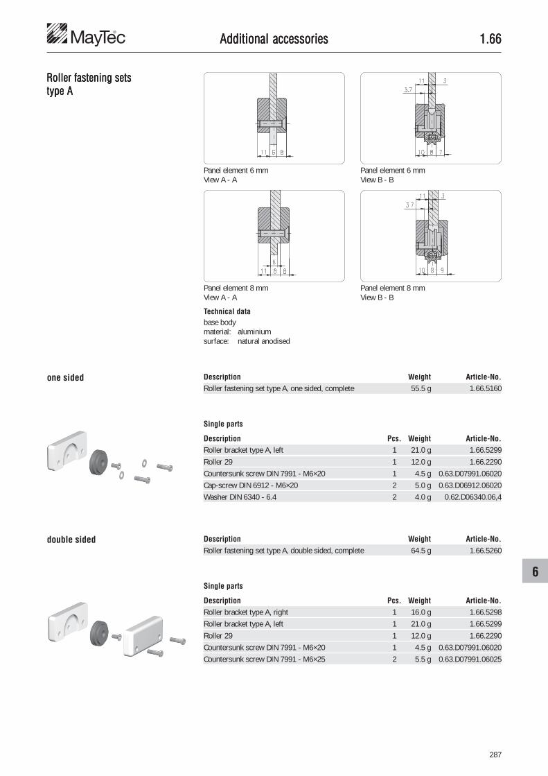
287
6
1.661.661.661.661.66
Roller fastening setsRoller fastening setsRoller fastening setsRoller fastening setsRoller fastening setstype Atype Atype Atype Atype A
Technical database bodymaterial: aluminiumsurface: natural anodised
Panel element 6 mmView A - A
one sided
Panel element 8 mmView A - A
Panel element 6 mmView B - B
Panel element 8 mmView B - B
double sided
Description Weight Article-No.Roller fastening set type A, one sided, complete 55.5 g 1.66.5160
Single parts
Description Pcs. Weight Article-No.Roller bracket type A, left 1 21.0 g 1.66.5299Roller 29 1 12.0 g 1.66.2290Countersunk screw DIN 7991 - M6×20 1 4.5 g 0.63.D07991.06020Cap-screw DIN 6912 - M6×20 2 5.0 g 0.63.D06912.06020Washer DIN 6340 - 6.4 2 4.0 g 0.62.D06340.06,4
Description Weight Article-No.Roller fastening set type A, double sided, complete 64.5 g 1.66.5260
Single parts
Description Pcs. Weight Article-No.Roller bracket type A, right 1 16.0 g 1.66.5298Roller bracket type A, left 1 21.0 g 1.66.5299Roller 29 1 12.0 g 1.66.2290Countersunk screw DIN 7991 - M6×20 1 4.5 g 0.63.D07991.06020Countersunk screw DIN 7991 - M6×25 2 5.5 g 0.63.D07991.06025
Additional accessoriesAdditional accessoriesAdditional accessoriesAdditional accessoriesAdditional accessories

288
1.661.661.661.661.66
Roller fastening setsRoller fastening setsRoller fastening setsRoller fastening setsRoller fastening setstype Btype Btype Btype Btype B
ApplicationThe roller fastening set allows the mountingof the roller into the panel element
CommentsMounting position of roller optionalA = 1.7 mm
2.7 mm
Guidance in profile slot
Guidance in twin track guide
Mounting on top side Mounting on bottom side
CommentsThe elongated hole in the panel elementallows to adjust the height tolerance and tounhinge the sliding door
Additional accessoriesAdditional accessoriesAdditional accessoriesAdditional accessoriesAdditional accessories

289
6
1.661.661.661.661.66
Roller fastening setsRoller fastening setsRoller fastening setsRoller fastening setsRoller fastening setstype Btype Btype Btype Btype B
ApplicationGuidance of sliding dooron top: sliding profile 30×14on bottom: twin track guide with profile
Technical database bodymaterial: aluminiumsurface: natural anodised
The slot in the panel element allows:• adjustment of height tolerance• removal of the sliding door
Mounting position of roller:dimension 6.7 = panel element 6 mmdimension 7.7 = panel element 8 mm
Description Weight Article-No.Roller fastening set type B, complete 62 g 1.66.5360
Single parts
Description Pcs. Weight Article-No.Roller bracket type B 1 21.0 g 1.66.5399Roller 29 1 12.0 g 1.66.2290Countersunk screw DIN 7991 - M6×20 1 4.5 g 0.63.D07991.06020Cap-screw DIN 6912 - M6×20 2 5.0 g 0.63.D06912.06020Washer DIN 6340 - 6.4 2 4.0 g 0.62.D06340.06,4
Additional accessoriesAdditional accessoriesAdditional accessoriesAdditional accessoriesAdditional accessories

290
1.661.661.661.661.66
Mounting adaptor for rollerMounting adaptor for rollerMounting adaptor for rollerMounting adaptor for rollerMounting adaptor for roller ApplicationFor fastening of rollers
CommentsSimple mounting, enables installationwithout dismounting of frameFmax = 1,000 N
Technical datamaterial: PA, black
Mounting elementsF-slot: threaded plate F M6 1.31.FM6E-slot: threaded plate E M6 1.31.EM6
threaded plate, heavy E M6 1.31.6EM6cap-screw DIN 6912, M6
Description Weight Article-No.Mounting adaptor for roller Ø8 9 g 1.66.70808
Additional accessoriesAdditional accessoriesAdditional accessoriesAdditional accessoriesAdditional accessories

291
6
1.661.661.661.661.66
� � � �
Edge rollerEdge rollerEdge rollerEdge rollerEdge roller ApplicationRoller conveyors for transporting boxes andcontainers• low noise• low friction operation due to double ball
bearings• simple assembly
Technical datamaterial:• roller: impact resistant plastic• axle: galvanisedcolour:• roller: blackbearings: steel or stainlessball bearings
on galvanised steel boltloading capacity:• static: 50 N• dynamic: 100 N
Single parts� edge roller� hexagon nut� shim� threaded plate
Mounting elementsthreaded plate E M8 1.31.EM8hexagon nut DIN 934 - M8 0.61.D00934.08washer DIN 125 - 8.4 0.62.D00125.A08,4
Description Weight Article-No.Edge roller E 51.0 g 1.66.7523860
Additional accessoriesAdditional accessoriesAdditional accessoriesAdditional accessoriesAdditional accessories

292
1.661.661.661.661.66
Roller fittingRoller fittingRoller fittingRoller fittingRoller fittingfor suspended doors
ApplicationSliding suspended doors made of profileframes for large openings and heavy doors
Technical databar length: 6 mmaterial: aluminiumsurface: natural anodised
Guidance for mounting on the floor
Alu C-trackfor suspended doors
Guidance for mounting on the profile frame
Description Weight Article-No.Alu C-track bar 3.6 kg 1.19.14532.60Alu C-track cut to length 0.6 kg 1.19.14532-A00A00/...
/... = length in mm
Additional accessoriesAdditional accessoriesAdditional accessoriesAdditional accessoriesAdditional accessories

293
6
1.661.661.661.661.66
Technical datamaterial: zinc diecastingsurface: bare4 ball bearing rollersmax. load capacity: 70 kg
Runnerfor suspended door
Stopperfor suspended door
Bottom guidefor suspended door
Frame guidefor suspended door
Rubber door stopfor suspended door
Technical datamaterial: plasticcolour: grey
Technical datamaterial: plasticcolour: grey
Technical datamaterial: aluminiumsurface: natural anodised
Technical datamaterial: rubbercolour: black
CommentsCountersink DIN 74 - M6 forcountersunk screw DIN 7991 - M6
Description Weight Article-No.Runner for suspended door 91 g 1.66.8020
Description Weight Article-No.Stopper for suspended door 21 g 1.66.8030
Description Weight Article-No.Bottom guide for suspended door 9 g 1.66.8040
Description Weight Article-No.Rubber door stop for suspended door 3 g 1.66.8060
Description Weight Article-No.Frame guide for suspended door 30 g 1.66.8050
countersinkDIN 74 - M6
Additional accessoriesAdditional accessoriesAdditional accessoriesAdditional accessoriesAdditional accessories
countersinkDIN 74 - M5
CommentsCountersink DIN 74 - M5 forcountersunk screw DIN 7991 - M5

294
1.661.661.661.661.66
RunnerRunnerRunnerRunnerRunnerfor sliding suspended doors
ApplicationSliding suspended doors made of profileframes for large openings and heavy doors
Runnerfor sliding suspended door
Description a b h Weight Article-No.Runner for sliding susp. door, PG 40 21.0 20.0 38.0 102 g 1.66.81140Runner for sliding susp. door, PG 45 23.5 22.5 43.0 114 g 1.66.81145
Technical datamaterial:• strap: VA• bolt: C45 K• distance bush: AlMg3max. load capacity: 100 kg
countersinkDIN 74 - M8
CommentsCountersink DIN 74 - M8 forcountersunk screw DIN 7991 - M8
Distance d = mismatch of Alu C-track
Additional accessoriesAdditional accessoriesAdditional accessoriesAdditional accessoriesAdditional accessories

295
6
1.661.661.661.661.66Additional accessoriesAdditional accessoriesAdditional accessoriesAdditional accessoriesAdditional accessories
Stopper Type 1for sliding suspended door
Description Weight Article-No.Stopper Type 1 for sliding suspended door, complete 63 g 1.66.8201055
Description Weight Article-No.Stopper Type 2 for sliding suspended door, complete 160 g 1.66.8202065
Stopper Type 2for sliding suspended door

296
1.671.671.671.671.67
Slot rollersSlot rollersSlot rollersSlot rollersSlot rollers ApplicationFor light running sliding doors
Technical datamaterial: PETPcolour: blackmax. static load: 8 kg/roller
Fastening elements (optional)threaded plate E M8 1.31.EM8threaded plate, heavy, E M8 1.31.6EM8T-Nut, E M8 1.32.EM8T-Nut for subs. insertion E, M8 1.32.4EM8
Description A Weight Article-No.Slot roller E3 4.45 24 g 1.67.42E3M8
Description A Weight Article-No.Slot roller E4 5.45 24 g 1.67.42E4M8
Additional accessoriesAdditional accessoriesAdditional accessoriesAdditional accessoriesAdditional accessories

297
6
1.671.671.671.671.67
X-X
A
BY-Y
Additional accessoriesAdditional accessoriesAdditional accessoriesAdditional accessoriesAdditional accessories
Guidance systemGuidance systemGuidance systemGuidance systemGuidance system ApplicationSlideway with sliding blocks e.g. for liftingtables and drawers
Slideway for lifting table
T-nut
Slideway for drawer
View "X"
View "Y"
sliding block
T-nut
sliding block
Details "A" and "B"

298
1.671.671.671.671.67Additional accessoriesAdditional accessoriesAdditional accessoriesAdditional accessoriesAdditional accessories
Clampingfor guidance system
Sliding blocks Technical datamaterial: PA6G oil,
(murlubric or similar)colour: blackmax. carrying capacity: p = 20 N/mm2
at • temperature 20°C• velocity 1 m/sec
Clamping with setscrew Clamping with clamping lever
Single parts for clamping
Description Article-No.T-nut sliding block 1.67.�M8Distance washer 1.67.2008Clamping lever 1.29.801030
Connector
Description for profile Article-No.Connector, screw-type, parallel, M8 30×30 1.21.3/4S5M8/7Connector, screw-type, parallel, M8 40×40 1.21.4/5S5M8/11Connector, screw-type, parallel, M8 45×45 1.21.45/55S5M8/11Connector, screw-type, parallel, M8 50×50 1.21.5/6S5M8/11Connector, screw-type, parallel, M8 60×60 1.21.6S1M8/11
Description F Weight Article-No.Sliding block F 1,500 N 11 g 1.67.F2F2
Description a b F Weight Article-No.Sliding block F/E3 19.6 3.2 1,500 N 15 g 1.67.F2E3Sliding block F/E4 20.6 4.2 1,500 N 15 g 1.67.F2E4
Description a b c F Weight Article-No.Sliding block E3 22.2 3.2 3.2 2,000 N 18 g 1.67.E3E3Sliding block E3/E4 23.2 3.2 4.2 2,000 N 18 g 1.67.E3E4Sliding block E4 24.2 4.2 4.2 2,000 N 23 g 1.67.E4E4

299
6
1.671.671.671.671.67
T-nut sliding blocks Technical datamaterial: PA6G oil (murlubric or similar)colour: black
Distance washer Technical datamaterial: PVCcolour: grey
Description D d Weight Article-No.Distance washer 22 8.3 3.0 g 1.67.2002Distance washer 28 13.0 3.0 g 1.67.2008
Description G Weight Article-No.T-nut sliding block F M6 1.5 g 1.67.FM6T-nut sliding block F M8 1.5 g 1.67.FM8
Description G Weight Article-No.T-nut sliding block E M6 3.0 g 1.67.EM6T-nut sliding block E M8 3.0 g 1.67.EM8
Additional accessoriesAdditional accessoriesAdditional accessoriesAdditional accessoriesAdditional accessories
Description G Weight Article-No.T-nut sliding block E 2×M6 17.0 g 1.67.E2M61400T-nut sliding block E 2×M8 16.6 g 1.67.E2M81400
Description Weight Article-No.T-nut sliding block E 2×M8 for Eco-Slide with clamping lever 15.6 g 1.67.E2M81408
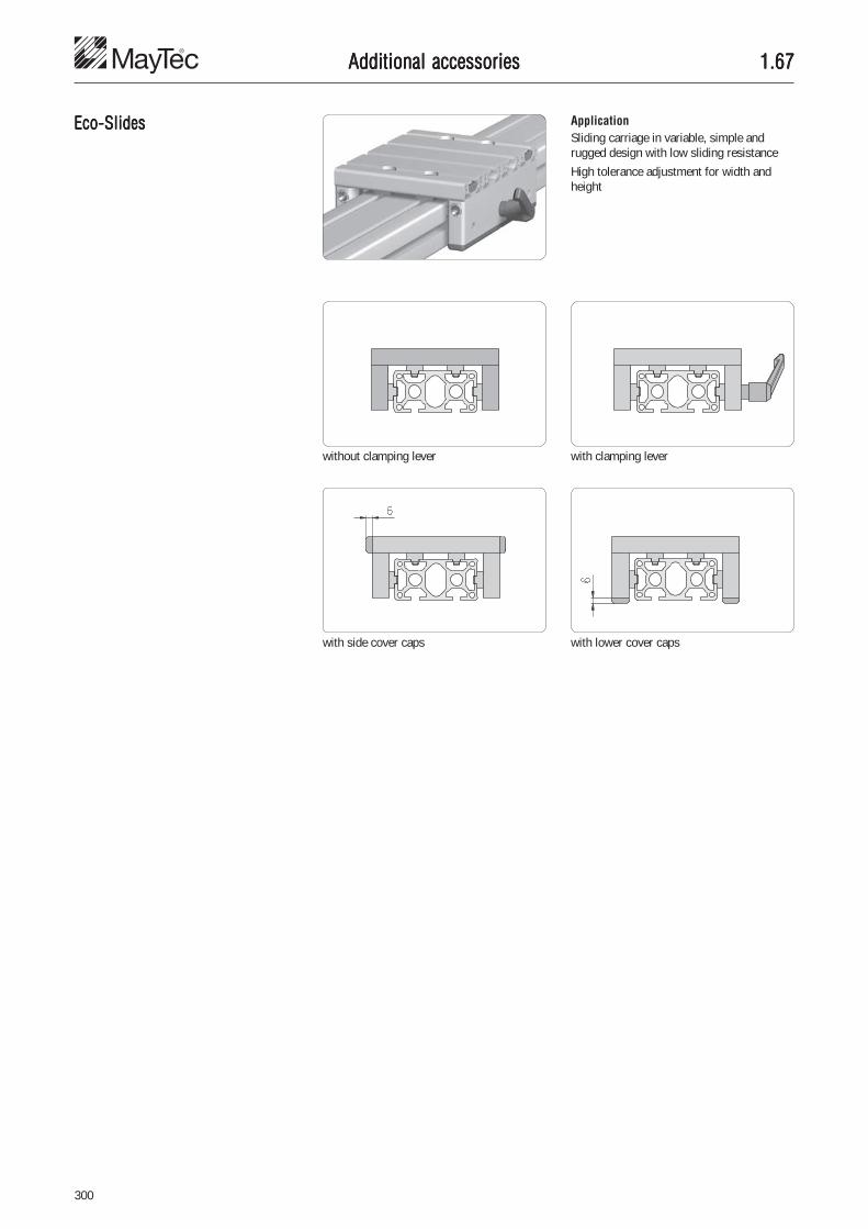
300
1.671.671.671.671.67
Eco-SlidesEco-SlidesEco-SlidesEco-SlidesEco-Slides ApplicationSliding carriage in variable, simple andrugged design with low sliding resistance
High tolerance adjustment for width andheight
with lower cover capswith side cover caps
with clamping leverwithout clamping lever
Additional accessoriesAdditional accessoriesAdditional accessoriesAdditional accessoriesAdditional accessories

301
6
1.671.671.671.671.67
Eco-Slidefor profile group 30F-slot
Description B L Weight Article-No.Eco-Slide, PG 30 - 30F 73 510 g 1.67.S101.030030FEco-Slide, PG 30 - 30F, with clamping lever 73 549 g 1.67.S102.030030F
Description B L Weight Article-No.Eco-Slide, PG 30 - 60F 103 600 g 1.67.S101.030060FEco-Slide, PG 30 - 60F, with clamping lever 103 639 g 1.67.S102.030060F
Description B L Weight Article-No.Eco-Slide, PG 30 - 100F 143 720 g 1.67.S101.030100FEco-Slide, PG 30 - 100F, with clamping lever 143 759 g 1.67.S102.030100F
Description B L Weight Article-No.Eco-Slide, PG 30 - 150F 193 810 g 1.67.S101.030150FEco-Slide, PG 30 - 150F, with clamping lever 193 849 g 1.67.S102.030150F
Width of profile
30 mm
60 mm
100 mm
150 mm
Additional accessoriesAdditional accessoriesAdditional accessoriesAdditional accessoriesAdditional accessories
Technical dataloading capacity: max. 1,000 N

302
1.671.671.671.671.67
Eco-Slidefor profile group 40E-slot
Description B L Weight Article-No.Eco-Slide, PG 40 - 40E 83 555 g 1.67.S101.040040EEco-Slide, PG 40 - 40E, with clamping lever 83 594 g 1.67.S102.040040E
Description B L Weight Article-No.Eco-Slide, PG 40 - 80E 123 670 g 1.67.S101.040080EEco-Slide, PG 40 - 80E, with clamping lever 123 709 g 1.67.S102.040080E
Description B L Weight Article-No.Eco-Slide, PG 40 - 120E 163 790 g 1.67.S101.040120EEco-Slide, PG 40 - 120E, with clamping lever 163 829 g 1.67.S102.040120E
Description B L Weight Article-No.Eco-Slide, PG 40 - 160E 203 910 g 1.67.S101.040160EEco-Slide, PG 40 - 160E, with clamping lever 203 949 g 1.67.S102.040160E
Width of profile
40 mm
80 mm
120 mm
160 mm
Additional accessoriesAdditional accessoriesAdditional accessoriesAdditional accessoriesAdditional accessories
Technical dataloading capacity: max. 1,000 N

303
6
1.671.671.671.671.67
Eco-Slidefor profile group 45E-slot
Description B L Weight Article-No.Eco-Slide, PG 45 - 45E 88 665 g 1.67.S101.045045EEco-Slide, PG 45 - 45E, with clamping lever 88 704 g 1.67.S102.045045E
Description B L Weight Article-No.Eco-Slide, PG 45 - 90E 133 710 g 1.67.S101.045090EEco-Slide, PG 45 - 90E, with clamping lever 133 749 g 1.67.S102.045090E
Width of profile
45 mm
90 mm
Additional accessoriesAdditional accessoriesAdditional accessoriesAdditional accessoriesAdditional accessories
Technical dataloading capacity: max. 1,000 N

304
1.681.681.681.681.68
Hanging bracketHanging bracketHanging bracketHanging bracketHanging bracket ApplicationElement for mounting unhingeable fenceelements
CommentsElements needed for mounting:• cap-screw DIN 6912 M8×12
with threaded plate• T-Nut for subsequent insertion M8
with cap-screw DIN 6912 M8×10• parallel-connector with F-head
Technical datamaterial: aluminiumstrength: F25surface: natural anodised
The connector cross bushing can be fixed atthe front or back
Description Weight Article-No.Hanging bracket 16 g 1.68.201050
Additional accessoriesAdditional accessoriesAdditional accessoriesAdditional accessoriesAdditional accessories

305
6
1.691.691.691.691.69
Suspended gliderSuspended gliderSuspended gliderSuspended gliderSuspended glider
Carabine swivelCarabine swivelCarabine swivelCarabine swivelCarabine swivel
ApplicationElement for tool suspension in MayTec-profile
Technical datamaterial: PA-GFcolour: blackmax. static load: 300 N
Technical datamaterial: steelsurface: galvanised
Description Weight Article-No.Suspended glider F 10 g 1.69.F010
Description Weight Article-No.Suspended glider E 10 g 1.69.E010
Description Weight Article-No.Carabine swivel 60×6 27 g 1.69.1606
Additional accessoriesAdditional accessoriesAdditional accessoriesAdditional accessoriesAdditional accessories

306
1.701.701.701.701.70Electrical accessoriesElectrical accessoriesElectrical accessoriesElectrical accessoriesElectrical accessories
Potential equalisationPotential equalisationPotential equalisationPotential equalisationPotential equalisation ApplicationGround connections to establish thepotential equalisation between two profilesThe serration at the bottom of the sockethead of the connector pushes through theanodised coating of the profiles and thusprovides the electrical contact
CommentsSuitable to equalise charge accumulationsNot suitable for higher currents
Technical dataLow current measurements in accordancewith DIN VDE 0413, Part 4 for the control ofprotective circuits, earthing circuits andpotential equalisation methods through lowresistance connections for protectionagainst dangerous currents
contact
anodised coating
Description Article-No.Connector, universal, grounding, PG 20 1.21.2F0EConnector, universal, grounding, PG 30 1.21.3F0EConnector, universal, grounding, PG 40 1.21.4F0EConnector, universal, grounding, PG 45 1.21.45F0EConnector, universal, grounding, PG 50 1.21.5F0EConnector, universal, grounding, PG 60 1.21.6F0E
Description Article-No.Connector, universal, grounding, PG 20 1.21.2E0EConnector, universal, grounding, PG 30 1.21.3E0EConnector, universal, grounding, PG 40 1.21.4E0EConnector, universal, grounding, PG 45 1.21.45E0EConnector, universal, grounding, PG 50 1.21.5E0EConnector, universal, grounding, PG 60 1.21.6E0E
Resistance values with DC currentof more than 200 mA
with 1.0 m alu-profile
without connector 0.11 �
with 1 standard connector > 2 M�
with 1 univ. grounding connector 0.11 �
CommentsMore grounding connectors� Connectors 1.2A

307
7
1.701.701.701.701.70
Ground connectionsGround connectionsGround connectionsGround connectionsGround connections ApplicationCouplings for grounding of anodisedprofiles
CommentsThe grounding is caused by breaking theanodised layer at the bottom of the slot andat the profile's front side
Description Weight Article-No.Ground connection F, M6 74 g 1.70.10FM6
Single partsT-Nut for subseqent insertion F, M6Setscrew DIN 914 - M6×25 - V2AFan type lock washer DIN 6798 - A6.4 - V2AHexagon nut DIN 439 - M6 - MsWasher with chamfer DIN 125 - B6.4 - Ms
Description Weight Article-No.Ground connection E, M8 146 g 1.70.10EM8
Single partsT-Nut for subseqent insertion E, M8Setscrew DIN 914 - M8×25 - V2AFan type lock washer DIN 6798 - A8.4 - V2AHexagon nut DIN 439 - M8 - MsWasher with chamfer DIN 125 - B8.4 - Ms
Electrical accessoriesElectrical accessoriesElectrical accessoriesElectrical accessoriesElectrical accessories

308
1.711.711.711.711.71
Cable and hose clampCable and hose clampCable and hose clampCable and hose clampCable and hose clamp ApplicationFixing element for cables and hoses up toØ12 mm
Mounting on profiles Ømax = 12 mm for cables and hoses
Technical datamaterial: PAcolour: black
Description Weight Article-No.Cable and hose clamp 8 g 1.71.1010
Fastening elements for E-slotcap-screw DIN 6912 M4×12T-Nut for subs. insertion, with leaf spring E, M4 1.32.4EM4spring-nut E, M4 1.33.EM4T-slot nut E, M4 1.34.10EM4
Electrical accessoriesElectrical accessoriesElectrical accessoriesElectrical accessoriesElectrical accessories

309
7
1.711.711.711.711.71
Block for cable binderBlock for cable binderBlock for cable binderBlock for cable binderBlock for cable binder,,,,,Cross-blocks for cable binderCross-blocks for cable binderCross-blocks for cable binderCross-blocks for cable binderCross-blocks for cable binderfront-sided insertion,
Cable binderCable binderCable binderCable binderCable binder
front-sided insertion
Block for cable binder Cross-block for cable binder
Technical datamaterial: PAcolour: black
ApplicationElement for fixing single cables and hosesor large quantities
CommentsCounterbore DIN 74 - M5 forcap-screw DIN 6912 - M5
Block for cable binder
Cross-blocks for cable binderfront-sided insertion
Cable binderdetachable
Description B×L Weight Article-No.Cable binder, detachable 4.8×145 0.7 g 1.71.2048145Cable binder, detachable 9.0×140 1.9 g 1.71.2090140
Description Weight Article-No.Block for cable binder 1.6 g 1.71.2010
Description a Weight Article-No.Cross-block for cable binder F 2.2 4.0 g 1.71.2020F2Cross-block for cable binder E3 3.0 4.0 g 1.71.2020E3Cross-block for cable binder E4 4.0 4.0 g 1.71.2020E4
counterboreDIN 74 - M5
Electrical accessoriesElectrical accessoriesElectrical accessoriesElectrical accessoriesElectrical accessories

310
1.711.711.711.711.71
Installation ringsInstallation ringsInstallation ringsInstallation ringsInstallation rings
Technical datamaterial: PA-GFcolour: black
ApplicationElement for fixing large quantities of cablesand hosesThe rings can be opened for insertion
Description D s Weight Article-No.Installation ring Ø28.5 6.0 5 g 1.71.30285Installation ring Ø36.5 6.0 6 g 1.71.30365Installation ring Ø47.5 7.5 8 g 1.71.30475Installation ring Ø56.5 7.5 9 g 1.71.30565
CommentsDelivery unit incl. screw
Electrical accessoriesElectrical accessoriesElectrical accessoriesElectrical accessoriesElectrical accessories

311
7
1.721.721.721.721.72
Mounting set for 19“ profileMounting set for 19“ profileMounting set for 19“ profileMounting set for 19“ profileMounting set for 19“ profile ApplicationFastening set for the assembly of 19" plug-inunits and 19" profiles
Technical datascrew and nut: steel, galvanisedplate and socket washer: PA, blackdelivery unit: PU with 10 mounting sets
Dimensions for front panels and housings according to DIN 41494
19“-profiles � Special profiles 1.19
Form U Form V Form W
distance distance
dist
ance
distance
Description Weight Article-No.Mounting set for 19" profile 70 g 1.72.2010.10
Electrical accessoriesElectrical accessoriesElectrical accessoriesElectrical accessoriesElectrical accessories

312
1.731.731.731.731.73
Safety switchesSafety switchesSafety switchesSafety switchesSafety switches
Description Weight Article-No.Safety switch with 1 safety contact 100 g 1.73.3010with 5 N - lock-in position
Description Weight Article-No.Safety switch with 1 safety contact and 1 alarm contact 125 g 1.73.3020with 5 N - lock-in position
Description Weight Article-No.Safety switch with 1 closing and 1 positioning monitoring 480 g 1.73.3030
ApplicationSafety switch for the electrical interlockingof swinging or sliding doors
CommentsSmallest possible radius of operation of 150mm
with 1 safety contact
with 1 safety contact and1 alarm contact
with 1 closing and 1 positioningmonitoring
Technical dataSchmersal: Type AZ 15 zvrk-M16-2254IP 67 230V 4A
Technical dataSchmersal: Type AZ 16 zvrk-M16-2254IP 67 230V 4A
Technical dataSchmersal: Type AZM161sk - 33rk-24V-M16IP 65
CommentsLocking mechanism by springReleasing by solenoid(closed-circuit system)24V electrical potential of coil
Electrical accessoriesElectrical accessoriesElectrical accessoriesElectrical accessoriesElectrical accessories

313
7
1.731.731.731.731.73
Safety switchesSafety switchesSafety switchesSafety switchesSafety switchesAZ 17
Guard locking devicesGuard locking devicesGuard locking devicesGuard locking devicesGuard locking devicesAZM 170
Description Weight Article-No.Safety switch AZ 17-11 zk 90 g 1.73.3111with 1 positive-break safety contact
1 no contact
Safety switch AZ 17-02 zk 90 g 1.73.3112with 2 positive-break safety contacts
Description Weight Article-No.Guard locking device AZM 170-11 zka 300 g 1.73.3131with 1 positive-break safety contact
1 no contact
Guard locking device AZM 170-02 zka 300 g 1.73.3132with 2 positive-break safety contacts
Description Weight Article-No.Guard locking device AZM 170-11 zk - 024 300 g 1.73.3121with 1 positive-break safety contact
1 no contact24V electrical potential of coil
Guard locking device AZM 170-02 zk - 024 300 g 1.73.3122with 2 positive-break safety contacts
24V electrical potential of coil
ApplicationSafety switch for the electrical interlockingof swinging or sliding doors
Technical dataSchmersal: Type AZ 17
4A / 230 VAC IP 67
CommentsEspecially suitable for cramped mountingspaces
Technical dataSchmersal: Type AZM 170
4A / 230 VAC IP 67
CommentsLocking mechanism by springReleasing by solenoid(closed-circuit system)
CommentsLocking mechanism by solenoidReleasing by spring(working current principle)
Electrical accessoriesElectrical accessoriesElectrical accessoriesElectrical accessoriesElectrical accessories

314
1.731.731.731.731.73
Safety interlocking-mountingsSafety interlocking-mountingsSafety interlocking-mountingsSafety interlocking-mountingsSafety interlocking-mountingsfor swinging door
ApplicationMounting element for electrical interlockingswitches
CommentsAssembly onprofile 30×30profile 40×40profile 40×80
Technical datamaterial: aluminiumsurface: natural anodised
for swinging door
with lock for swinging door
Description Weight Article-No.Safety interlocking-mounting 46 g 1.73.4010for swinging door
Description Weight Article-No.Safety interlocking-mounting 183 g 1.73.4020with lock for swinging door
Electrical accessoriesElectrical accessoriesElectrical accessoriesElectrical accessoriesElectrical accessories

315
7
1.731.731.731.731.73
Safety interlocking-mountingsSafety interlocking-mountingsSafety interlocking-mountingsSafety interlocking-mountingsSafety interlocking-mountingsfor sliding door
Description Weight Article-No.Contact bracket-mounting 41 g 1.73.4030for sliding door
Description Weight Article-No.Safety interlocking-mounting 70 g 1.73.4040for sliding door
ApplicationMounting element for the electricalinterlocking of sliding doors
CommentsAssembly onprofile 30×30profile 40×40profile 40×80
Technical datamaterial: aluminiumsurface: natural anodised
Contact bracket-mountingfor sliding door
Safety interlocking-mountingfor sliding door
Electrical accessoriesElectrical accessoriesElectrical accessoriesElectrical accessoriesElectrical accessories

316
1.731.731.731.731.73
Safety interlocking-mountingsSafety interlocking-mountingsSafety interlocking-mountingsSafety interlocking-mountingsSafety interlocking-mountingsAZ 17AZ 17AZ 17AZ 17AZ 17for swinging door
ApplicationFastening elements for:• safety switches AZ 17• safety closing AZM 170 at sliding doors
Activation keyMounting vertical to swivel radius
Activation keyMounting horizontal to swivel radius
DeliveryIncl. lock washers DIN 9021 Ø4.3 mmfor mounting activation key
lock washer
Description Weight Article-No.Safety interlocking-mounting AZ 17 26 g 1.73.4110for swinging door
CommentsAssembly onprofile 30×30profile 40×40profile 40×80
Technical datamaterial: aluminiumsurface: natural anodised
Electrical accessoriesElectrical accessoriesElectrical accessoriesElectrical accessoriesElectrical accessories

317
7
1.731.731.731.731.73
� � � �
� � � �
�
ApplicationFastening elements for:• safety switches AZ 17• safety closing AZM 170 at sliding doors
Safety interlocking-mountingsSafety interlocking-mountingsSafety interlocking-mountingsSafety interlocking-mountingsSafety interlocking-mountingsAZ 17AZ 17AZ 17AZ 17AZ 17for sliding door
Mounting position:Safety switch parallel to sliding door
Mounting position:Safety switch across to sliding door
Fastening plate horizontal Fastening plate vertical
Fixing at cross profile Fixing at longitudinal profile
� Contact bracket-mounting AZ 17� Safety interlocking-mounting AZ 17
� Contact bracket-mounting AZ 17� Safety interlocking-mounting AZ 17� Angle for safety interlocking-
mounting AZ 17
Electrical accessoriesElectrical accessoriesElectrical accessoriesElectrical accessoriesElectrical accessories

318
1.731.731.731.731.73
Safety interlocking-mountingsSafety interlocking-mountingsSafety interlocking-mountingsSafety interlocking-mountingsSafety interlocking-mountingsAZ 17AZ 17AZ 17AZ 17AZ 17for sliding door
Contact bracket-mounting AZ 17for sliding door
Safety interlocking-mounting AZ 17for sliding door
Angle for safety interlocking-mounting AZ 17for sliding door
CommentsCountersink DIN 74 - M5 forcountersunk screw DIN 7991 - M5
CommentsAssembly onprofile 30×30profile 40×40profile 40×80
Technical datamaterial: aluminiumsurface: natural anodised
Description a Weight Article-No.Contact bracket-mounting AZ 17 for sliding door, L 30 15 16 g 1.73.4123Contact bracket-mounting AZ 17 for sliding door, L 40 25 19 g 1.73.4124Contact bracket-mounting AZ 17 for sliding door, L 50 35 21 g 1.73.4125
Description Weight Article-No.Safety interlocking-mounting AZ 17 for sliding door 62 g 1.73.4130
Description Weight Article-No.Angle for safety interlocking-mounting AZ 17 for sliding door 30 g 1.73.4140
countersinkDIN 74 - M5
Electrical accessoriesElectrical accessoriesElectrical accessoriesElectrical accessoriesElectrical accessories

319
7
1.731.731.731.731.73
Sensor bracketsSensor bracketsSensor bracketsSensor bracketsSensor brackets ApplicationFor fastening of sensors
AssemblyThe toothed lock washer is fixed in profileslot and guarantees a reliable positioning
Technical datamaterial: PA, black
Fastening elementscap-screw DIN 6912, M4
Description D Weight Article-No.Sensor bracket 8 Ø6.5 5.5 g 1.73.80806Sensor bracket 8 Ø8 5.4 g 1.73.80808Sensor bracket 8 Ø12 4.6 g 1.73.80812
Electrical accessoriesElectrical accessoriesElectrical accessoriesElectrical accessoriesElectrical accessories

320
1.741.741.741.741.74
Electrical installation trunkingElectrical installation trunkingElectrical installation trunkingElectrical installation trunkingElectrical installation trunking ApplicationTo supply machines and work stations with:• alternating current• high-tension current• air
Mounting direct to profile Mounting with connection plate
E-trunking coupling pin
Description Weight Article-No.E-trunking Alu, 68×130, bar 6 m 13 kg 1.74.1101.60E-trunking Alu, 68×130, cut to length 2.17 kg/m 1.74.1101-A00A00/...
/... = length in mm
Description Weight Article-No.E-trunking pre-cut lid Alu, bar 6 m 5 kg 1.74.1102.60E-trunking pre-cut lid Alu, cut to length 834 g/m 1.74.1102-A00A00/...
E-trunking pre-cut lid PVC, light grey, bar 2 m 760 g 1.74.1103.20E-trunking pre-cut lid PVC, l. grey, cut to length 380 g/m 1.74.1103-A00A00/...
/... = length in mm
Description Weight Article-No.E-trunking end cap Alu 230 g 1.74.1104
E-trunking Alu, 68×130
E-trunking pre-cut lid
Description Weight Article-No.E-trunking coupling pin 3 g 1.74.1105
E-trunking end cap
CommentsCoupling pin for positioning and elongatingthe electrical trunking
Electrical accessoriesElectrical accessoriesElectrical accessoriesElectrical accessoriesElectrical accessories

321
7
1.741.741.741.741.74
Description Weight Article-No.E-trunking partition, bar 2 m 540 g 1.74.1107.20E-trunking partition, cut to length 270 g/m 1.74.1107-A00A00/...
/... = length in mm
Description Weight Article-No.E-trunking earth terminal 6.8 g 1.74.1106
Description Weight Article-No.E-trunking clip 7 g 1.74.1108
Description L Weight Article-No.E-trunking terminal strip, 4gang 59 43 g 1.74.11094E-trunking terminal strip, 5gang 69 50 g 1.74.11095
Description Weight Article-No.Socket 150 g 1.74.2201
Single partsSocket insert 76 g 1.74.2201/01Socket box, black 68 g 1.74.2xxx/01Mains cable cleat 6 g 1.74.2xxx/02
Description Weight Article-No.Socket with hinged cover 163 g 1.74.2202
Single partsSocket with hinged cover 90 g 1.74.2202/01Socket box, black 67 g 1.74.2xxx/01Mains cable cleat 6 g 1.74.2xxx/02
CommentsClip to support partition
E-trunking earth terminal
E-trunking partition
E-trunking clip
E-trunking terminal strip
Socket
Socket with hinged cover
Electrical accessoriesElectrical accessoriesElectrical accessoriesElectrical accessoriesElectrical accessories

322
1.741.741.741.741.74
Description Weight Article-No.Rocker control switch 154 g 1.74.2302
Single partsRocker control switch insert 57 g 1.74.2302/01Rocker for control switch 24 g 1.74.2302/02Socket box, black 67 g 1.74.2xxx/01Mains cable cleat 6 g 1.74.2xxx/02
Description Weight Article-No.Rocker switch 137 g 1.74.2301
Single partsRocker switch insert 46 g 1.74.2301/01Rocker for switch 18 g 1.74.2301/02Socket box, black 67 g 1.74.2xxx/01Mains cable cleat 6 g 1.74.2xxx/02
Description Weight Article-No.Pre-cut lid, Alu, 1gang 82 g 1.74.3111Pre-cut lid, PVC, 1gang, light grey 28 g 1.74.3121
Description Weight Article-No.Pre-cut lid, Alu, 2gang 83 g 1.74.3112Pre-cut lid, PVC, 2gang, light grey 59 g 1.74.3122
Description Weight Article-No.Pre-cut lid, Alu, 3gang 113 g 1.74.3113Pre-cut lid, PVC, 3gang, light grey 88 g 1.74.3123
Description Weight Article-No.Cover frame, 1gang 21 g 1.74.4111
Rocker switch
Rocker control switch
Pre-cut lid, 1gang
Pre-cut lid, 2gang
Pre-cut lid, 3gang
Cover frame, 1gang
Electrical accessoriesElectrical accessoriesElectrical accessoriesElectrical accessoriesElectrical accessories

323
7
1.741.741.741.741.74
Description Weight Article-No.Cover frame, 2gang 39 g 1.74.4112
Description Weight Article-No.Cover frame, 3gang 58 g 1.74.4113
Description Pcs. Weight Article-No.CEE heavy-power socket 16 A 1 915 g 1.74.6116
Single partsCEE heavy-power socket with lid, 16 A 1 645 g 1.74.6116/01CEE socket box 1 225 g 1.74.61xx/02CEE pre-cut lid, Alu 1 45 g 1.74.61xx/03
Description Pcs. Weight Article-No.Miniature circuit breaker, 10 A, 4gang 1 763 g 1.74.5110
Single partsMiniature circuit breaker, flat, unipolar, 10 A 4 100 g 1.74.5110/01Circuit breaker mounting box, 4gang 1 230 g 1.74.51xx/02Pre-cut lid, Alu 1 133 g 1.74.51xx/03
Description Pcs. Weight Article-No.Miniature circuit breaker, 16 A, 4gang 1 763 g 1.74.5116
Single partsMiniature circuit breaker, flat, unipolar, 16 A 4 100 g 1.74.5116/01Circuit breaker mounting box, 4gang 1 230 g 1.74.51xx/02Pre-cut lid, Alu 1 133 g 1.74.51xx/03
Cover frame, 2gang
Miniature circuit breaker 10 A
Cover frame, 3gang
Miniature circuit breaker 16 A
CEE heavy-power socket 16 A
Electrical accessoriesElectrical accessoriesElectrical accessoriesElectrical accessoriesElectrical accessories

324
1.751.751.751.751.75
�
��
�
Electrical installation trunkingElectrical installation trunkingElectrical installation trunkingElectrical installation trunkingElectrical installation trunking ApplicationInstallation trunking for electrical andpneumatic lines
Description Weight Article-No.E-trunking Alu 40×20, bar 6 m 1.80 kg 1.19.204020G.60E-trunking Alu 40×20, cut to length 0.30 kg/m 1.19.204020G-A00A00/...
/... = length in mm
E-trunking Alu
Description Weight Article-No.E-trunking Alu 40×80, bar 6 m 7.20 kg 1.19.204080G.60E-trunking Alu 40×80, cut to length 1.20 kg/m 1.19.204080G-F00F00/...
/... = length in mm
Description Weight Article-No.E-trunking Alu 80×40, bar 6 m 5.10 kg 1.19.208040G.60E-trunking Alu 80×40, cut to length 0.85 kg/m 1.19.208040G-F00F00/...
/... = length in mm
Technical datamaterial: aluminiumsurface: natural anodised
Ø3, fastening of cover cap
Centre groove for fasteninglid to E-trunking
Fastening of lidwithsheet metal screw0.63.D07981.3,5×9,5
Description Weight Article-No.E-trunking Alu 40×40, bar 6 m 3.66 kg 1.19.204040G.60E-trunking Alu 40×40, cut to length 0.61 kg/m 1.19.204040G-A00A00/...
/... = length in mm
Electrical accessoriesElectrical accessoriesElectrical accessoriesElectrical accessoriesElectrical accessories
Centre groove for fastening E-trunkingto profile
Possibilities of fasteningbutton-headed screw M5×120.63.WN7380.05012
with:• threaded plate EM5, 1.31.EM5• T-nut for subs. insertion, with leaf spring
EM5, 1.32.4EM5• T-slot nut EM5, 1.34.10EM5
Mounting
Lid profile to base profile
Mounting
Base profile to profile with E-slot
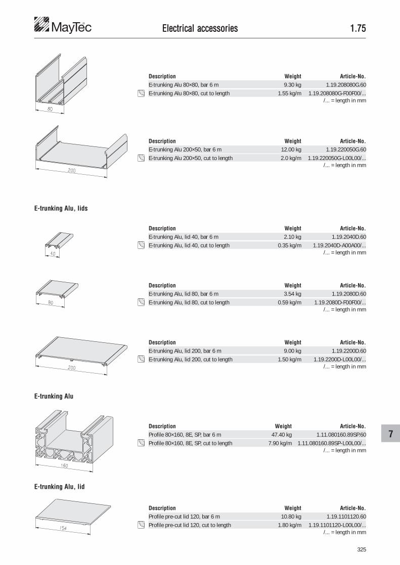
325
7
1.751.751.751.751.75
E-trunking Alu, lids
Description Weight Article-No.E-trunking Alu, lid 80, bar 6 m 3.54 kg 1.19.2080D.60E-trunking Alu, lid 80, cut to length 0.59 kg/m 1.19.2080D-F00F00/...
/... = length in mm
Description Weight Article-No.E-trunking Alu, lid 40, bar 6 m 2.10 kg 1.19.2040D.60E-trunking Alu, lid 40, cut to length 0.35 kg/m 1.19.2040D-A00A00/...
/... = length in mm
Electrical accessoriesElectrical accessoriesElectrical accessoriesElectrical accessoriesElectrical accessories
Description Weight Article-No.E-trunking Alu 200×50, bar 6 m 12.00 kg 1.19.220050G.60E-trunking Alu 200×50, cut to length 2.0 kg/m 1.19.220050G-L00L00/...
/... = length in mm
Description Weight Article-No.E-trunking Alu, lid 200, bar 6 m 9.00 kg 1.19.2200D.60E-trunking Alu, lid 200, cut to length 1.50 kg/m 1.19.2200D-L00L00/...
/... = length in mm
E-trunking Alu
E-trunking Alu, lid
Description Weight Article-No.Profile 80×160, 8E, SP, bar 6 m 47.40 kg 1.11.080160.89SP.60Profile 80×160, 8E, SP, cut to length 7.90 kg/m 1.11.080160.89SP-L00L00/...
/... = length in mm
Description Weight Article-No.Profile pre-cut lid 120, bar 6 m 10.80 kg 1.19.1101120.60Profile pre-cut lid 120, cut to length 1.80 kg/m 1.19.1101120-L00L00/...
/... = length in mm
Description Weight Article-No.E-trunking Alu 80×80, bar 6 m 9.30 kg 1.19.208080G.60E-trunking Alu 80×80, cut to length 1.55 kg/m 1.19.208080G-F00F00/...
/... = length in mm

326
1.751.751.751.751.75
E-trunking Alu, end plates
Description Weight Article-No.E-trunking Alu, end plate 40×20 6.0 g 1.75.2040202
Description Weight Article-No.E-trunking Alu, end plate 40×40 12.3 g 1.75.2040402
Description Weight Article-No.E-trunking Alu, end plate 40×80 25.0 g 1.75.2040802
Description Weight Article-No.E-trunking Alu, end plate 80×80 48.0 g 1.75.2080802
Electrical accessoriesElectrical accessoriesElectrical accessoriesElectrical accessoriesElectrical accessories
Description Weight Article-No.E-trunking Alu, end plate 200×50 80.7 g 1.75.2200503
Description Weight Article-No.E-trunking Alu, end plate 80×40 25.0 g 1.75.2080402

327
7
1.751.751.751.751.75Electrical accessoriesElectrical accessoriesElectrical accessoriesElectrical accessoriesElectrical accessories
Description Weight Article-No.E-trunking Alu 40×20, Clips, bar 6 m 3.00 kg 1.19.214020G.60E-trunking Alu 40×20, Clips, cut to length 0.50 kg/m 1.19.214020G-A00A00/...
/... = length in mm
E-trunking Alu, for clips
Description Weight Article-No.E-trunking Alu, end plate 40×20, Clips 6.0 g 1.75.2140202
E-trunking Alu, lid
Description Weight Article-No.E-trunking Alu, lid 40, bar 6 m 2.10 kg 1.19.2040D.60E-trunking Alu, lid 40, cut to length 0.35 kg/m 1.19.2040D-A00A00/...
/... = length in mm
Electrical installation trunkingElectrical installation trunkingElectrical installation trunkingElectrical installation trunkingElectrical installation trunkingfor clips
ApplicationClip-system for quick assembly of theE-trunking
Technical datamaterial: aluminiumsurface: natural anodised
E-trunking Alu, end plate
Clip for E-trunking Alu Technical datamaterial: Murytal Ccolour: natural
Description L Weight Article-No.Clip E3 11 3.0 g 1.75.1000E3Clip E4 12 3.0 g 1.75.1000E4

328
1.811.811.811.811.81
Corner elementsCorner elementsCorner elementsCorner elementsCorner elementsfor wire net mounting profile
ApplicationThis mounting profile allows simple and safeinstallation of screens
CommentsWire net mounting profile � 1.19.1423...
Outside corner
Inside corner
Description Weight Article-No.Corner element - outside 13 g 1.81.1010
Description Weight Article-No.Corner element - inside 6 g 1.81.1020
Mounting in the profile slot Fastening from the outside
Technical datamaterial: PA - GFcolour: black
Outside corner
Inside corner
Panel elementsPanel elementsPanel elementsPanel elementsPanel elements

329
8
1.811.811.811.811.81
Corner element 33Corner element 33Corner element 33Corner element 33Corner element 33for wire net mounting profile 33×10
Description Weight Article-No.Corner element 33 16 g 1.81.23310
ApplicationThis profile allows simple and safeinstallation of wire nets
CommentsWire net mounting profile 33×10� 1.19.1423...
Technical datamaterial: PA - GFcolour: black
Outside mounting
Outside corner Inside corner
Panel elementsPanel elementsPanel elementsPanel elementsPanel elements

330
1.811.811.811.811.81
Mounting socketsMounting socketsMounting socketsMounting socketsMounting sockets ApplicationFor stable and vibration free fastening ofwire nets
Assembly• plug terminal sockets at a distance of
about 270 mm on the wire net• push on profile• rotate mounting sockets with headless
setscrew DIN 913 M6×8 at an angleof 15°
Technical datamaterial:mounting socket: aluminium, natural
anodisedsetscrew: steel, galvanised
Description T Weight Article-No.Mounting socket, F 5 6 g 1.81.510F
Description T Weight Article-No.Mounting socket, E3 9 6 g 1.81.510E3
Description T Weight Article-No.Mounting socket, E4 10 6 g 1.81.510E4
setscrew
mounting socket wire net
View "A"
Panel elementsPanel elementsPanel elementsPanel elementsPanel elements
Delivery unitMounting socket incl. setscrew

331
8
1.821.821.821.821.82
Panel elementsPanel elementsPanel elementsPanel elementsPanel elements ApplicationPanel elements to cover machine frames,work stations, partition walls.
Panel element, fixing directly in the slot
Panel elements close to the outer contour bysubsequent slitting of the profiles
Panel elements close to the outer contour byfixing with angle or mounting block
Panel elementsPanel elementsPanel elementsPanel elementsPanel elements
Installation accessories � 1.41
Special slits � 1.1E.01
Mounting blocks � 1.64
Panel elements close to the outer contour byapplying panel profiles
Panel profiles � 1.14
Panel elements close to the outer contour byapplying wire net profiles
Wire net profiles � 1.15

332
1.821.821.821.821.82
ChipboardsChipboardsChipboardsChipboardsChipboardsboth sides coated with melamine
Solid plastic panelsSolid plastic panelsSolid plastic panelsSolid plastic panelsSolid plastic panelscoated with melamine
Technical datasurface: both sides coated with melaminestructure: pearlRAL 9002: grey-whiteformaldehydemission: complies to safety standards §9 paragraph 3light-fastness: point 6 as per DIN 53799temperature resistance: - 25°C to 130°Cchemical resistance: resistant against organic food, light acid contents and alkaline
solution, gasoline, oil, tested as per DIN 53799chipboard: high frequency glued laminated chipboard
Technical values on DIN 68765 and 53799bulk density: approx. 700 kg/m³thickness tolerance: +0.5 -0.3 mmweight: S = 8 mm 5.6 kg/m²
S = 16 mm 11.2 kg/m²S = 19 mm 13.3 kg/m²
cut to length: 1.82.���-99/����×����1.82.���-99/����×���� type1.82.���-99/����×���� length×width in mm
Description S RAL Weight Article-No.Chipboard 8 9002 32 kg 1.82.083.00Chipboard 16 9002 64 kg 1.82.163.00Chipboard 19 9002 75 kg 1.82.193.00
Description S RAL Weight Article-No.Solid plastic panel 4 9002 33 kg 1.83.043.00Solid plastic panel 8 9002 66 kg 1.83.083.00
Technical datasurface: both sides coated with melaminestructure: pearlRAL 9002: grey-whitesolid plastic panel: made of Phenolplastic high pressure plate (HPL) of laminated
material with all generally known merits of this substance.
Technical values on DIN 19926 and 53799bulk density: approx. 1,500 kg/m³thickness tolerance: -0.6 mmweight: S = 4 mm 6 kg/m²
S = 8 mm 12 kg/m²cut to length: 1.83.���-99/����×����
1.83.���-99/����×���� type1.83.���-99/����×���� length×width in mm
Panel elementsPanel elementsPanel elementsPanel elementsPanel elements

333
8
1.851.851.851.851.85
AcrAcrAcrAcrAcrylicylicylicylicylic
Description S Colour Weight Article-No.Acrylic xt 4 transparent 28.8 kg 1.86.041.00Acrylic xt 4 bronze 802 28.8 kg 1.86.042.00Acrylic xt 6 transparent 43.2 kg 1.86.061.00Acrylic xt 6 bronze 802 43.2 kg 1.86.062.00Acrylic xt 8 transparent 57.6 kg 1.86.081.00Acrylic xt 8 bronze 802 57.6 kg 1.86.082.00
Technical datathickness tolerance: ± 5%weight: S = 4 mm 4.8 kg/m²
S = 6 mm 7.2 kg/m²S = 8 mm 9.6 kg/m²
cut to length: 1.86.���-99/����×����1.86.���-99/����×���� type1.86.���-99/����×���� length×width in mm
ApplicationDoors, panels and guards
Panel elementsPanel elementsPanel elementsPanel elementsPanel elements
Description S Weight Article-No.Alu-plastic composite panel 4 17.2 kg 1.85.040.00Alu-plastic composite panel 6 22.8 kg 1.85.060.00
Alu-plastic composite panelsAlu-plastic composite panelsAlu-plastic composite panelsAlu-plastic composite panelsAlu-plastic composite panels CommentsThe anodised composite panels have contactstrips of 25 mm width on the short sides.
Technical dataalu-plastic composite panel: PE with alu coating on both sidessurface: natural anodised, E6/EV1temperature resistance: - 50°C to 80°Cchemical resistance: resistant against organic food, light acid contents and
alkaline solutions, gasoline, oilthickness tolerance: -0.6 mmweight: S = 4 mm 5.5 kg/m²
S = 6 mm 7.3 kg/m²cut to length: 1.85.���-99/����×����
1.85.���-99/����×���� type1.85.���-99/����×���� length×width in mm

334
1.871.871.871.871.87
Wire net, AluWire net, AluWire net, AluWire net, AluWire net, Alu
Description Weight Article-No.Wire net, Alu 3×20×20 92.5 kg 1.88.322.00Wire net, Alu 4×30×30 112.5 kg 1.88.433.00
ApplicationFor protective coverings and partition walls
Technical datamaterial: Aluminiumsurface: bareweight: 3×20×20 mm 1.85 kg/m²
4×30×30 mm 2.25 kg/m²length of ring: 25 mcut to length: 1.88.���-99/����×����
1.88.���-99/����×���� type1.88.���-99/����×���� length×width in mm
CommentsMounting in the profile:• with sponge rubber � 1.41.6��• with wire net m. prof. � 1.19.1423...• with wedge profile � 1.41.51E�.�• with framing profile � 1.41.710.�• with mounting sockets � 1.81.510��
Panel elementsPanel elementsPanel elementsPanel elementsPanel elements
Description S Colour Weight Article-No.Polycarbonate 4 transparent 28.8 kg 1.87.041.00Polycarbonate 4 bronze 885 28.8 kg 1.87.042.00Polycarbonate 6 transparent 43.2 kg 1.87.061.00Polycarbonate 6 bronze 885 43.2 kg 1.87.062.00Polycarbonate 8 transparent 57.6 kg 1.87.081.00Polycarbonate 8 bronze 885 57.6 kg 1.87.082.00
Polycarbonate (Makrolon)Polycarbonate (Makrolon)Polycarbonate (Makrolon)Polycarbonate (Makrolon)Polycarbonate (Makrolon)
Technical datathickness tolerance: +0.8 mmweight: S = 4 mm 4.8 kg/m²
S = 6 mm 7.2 kg/m²S = 8 mm 9.6 kg/m²
cut to length: 1.87.���-99/����×����1.87.���-99/����×���� type1.87.���-99/����×���� length×width in mm
ApplicationDoors, panels and guards with stringent security requirements as polycarbonate offers highimpact resistance and strength against breakage
Properties Acrylic Poly-xt carbonate
Mechanical properties 20°Cmaximum extent of flex MN/m² 107.9 68.7break / shear point % 5.5 > 110.0compression MN/m² 117.7 78.5elasticity MN/m² 3,188.0 2,256.0marring resistance J/m² 29.4 392.4impact resistance kJ/m² 19.6 no breaktensile strength MN/m² 73.6 68.7
Thermal propertiestemperature distortion according to ‘Vicat’ °C 110 170melting point °C 168 170temperature range under °C 70 130static load (max.)temperature range under °C -40 -100static load (min.)

335
8
1.881.881.881.881.88Panel elementsPanel elementsPanel elementsPanel elementsPanel elements
Grid, steelGrid, steelGrid, steelGrid, steelGrid, steelwelded
Description Weight Article-No.Grid, steel 3×25×25 8.9 kg 1.88.232525.00Grid, steel 4×40×40 9.8 kg 1.88.244040.00
ApplicationFor protective coverings and partition walls
Technical datamaterial: steelsurface: electrogalvanisedweight: 3×25×25 mm 8.9 kg/plate
4×40×40 mm 9.8 kg/platesize of plate: 2,000×1,000 mmcut to length: 1.88.���-99/����×����
1.88.���-99/����×���� type1.88.���-99/����×���� length×width in mm
CommentsMounting in the profile:• with sponge rubber � 1.41.6��• with wire net m. prof. � 1.19.1423...• with wedge profile � 1.41.51E�.�• with framing profile � 1.41.710.�• with mounting sockets � 1.81.510��
Wire net, steelWire net, steelWire net, steelWire net, steelWire net, steel
Description Weight Article-No.Wire net, steel 4×30×30 27 kg 1.88.143030.00Wire net, steel 4×40×40 24 kg 1.88.144040.00
ApplicationFor protective coverings and partition walls
Technical datamaterial: steelsurface: galvanisedweight: 4×30×30 mm 27 kg/plate
4×40×40 mm 24 kg/platesize of plate: 3,000×1,810 mmcut to length: 1.88.���-99/����×����
1.88.���-99/����×���� type1.88.���-99/����×���� length×width in mm
CommentsMounting in the profile:• with sponge rubber � 1.41.6��• with wire net m. prof. � 1.19.1423...• with wedge profile � 1.41.51E�.�• with framing profile � 1.41.710.�• with mounting sockets � 1.81.510��

336
1.90 (0.62)1.90 (0.62)1.90 (0.62)1.90 (0.62)1.90 (0.62)
�
� > �
�
WWWWWashersashersashersashersashers
Self locking washersSelf locking washersSelf locking washersSelf locking washersSelf locking washersDIN 25201
The cam angle � of the washers is largerthan the thread pitch � of the bolt.
Advantages• Maximum safety during the tightening of
the screw
• Reliable connection under extremevibration and dynamic loads
• Ease of assembly and disassembly
• Positive locking at low and high preloadlevels
• Same temperature characteristics asstandard nut & bolt
• Surface protection
• Reusable
The outside dimensions of the locking washer guarantees it's effectiveness even when used incountersuck holes. Washers with enlarged outer diameter (SP) in combination with flangednuts / bolts are recommended for use on large / long holes, painted surfaces or soft materials,e.g. aluminium.
Junker vibration test for bolt M12 (8.8)
Test results
Vibration test for long holes
Load cycles
Pre-
tens
ioni
ng fo
rce
(in K
N)
Flange nut with self locking washers SP(enlarged outer diameter)
Regular nut with self locking washers SP(enlarged outer diameter)
Regular nut with self locking washers(regular outer diameter)
Clam
p lo
ad (i
n KN
)
time (in seconds)
Vibration testbolt M8 (8.8) with clamp length 25 mm
Loosen
Regular nut M8 on bolt with self lockingwashers at 70% of yield pointRegular nut M8 on bolt, clamp length50 mmNylon inserted nutSplit ringRegular nut M8 on boltRegular nut M8 on bolt with self lockingwashers at 25% of yield point

337
9
1.90 (0.62)1.90 (0.62)1.90 (0.62)1.90 (0.62)1.90 (0.62)WWWWWashersashersashersashersashers
Description D h d Weight Article-No.Standard / steelSelf locking washers, M6 10.8 1.8 6.5 0.7 g 0.62.D2520106Self locking washers, M8 13.5 2.5 8.7 1.5 g 0.62.D2520108Self locking washers, M10 16.6 2.5 10.7 2.3 g 0.62.D2520110
Standard / stainless steelSelf locking washers, M6, SS 10.8 2.2 6.5 0.9 g 0.62.D2520106SSSelf locking washers, M8, SS 13.5 2.2 8.7 1.2 g 0.62.D2520108SSSelf locking washers, M10, SS 16.6 2.2 10.7 1.6 g 0.62.D2520110SS
SP / steelSelf locking washers, M6, SP 13.5 2.5 6.5 2.0 g 0.62.D2520106SPSelf locking washers, M8, SP 16.6 2.5 8.7 2.9 g 0.62.D2520108SPSelf locking washers, M10, SP 21.0 2.5 10.7 4.4 g 0.62.D2520110SP
SP / stainless steelSelf locking washers, M6, SPSS 13.5 2.2 6.5 1.6 g 0.62.D2520106SPSSSelf locking washers, M8, SPSS 16.6 2.2 8.7 2.4 g 0.62.D2520108SPSSSelf locking washers, M10, SPSS 21.0 2.2 10.7 3.7 g 0.62.D2520110SPSS
Hexagonal flange head screw DIN 6912 andself locking washers SP
Technical datamaterial:• steel: Zinc flake coated, pre-
assembled in pairs (glued)
• stainless steel: 1.4404, pre-assembled inpairs (glued)
Cylindrical head screw DIN 6912 with selflocking washers, standard
Do not use washers that are not secured inposition
T-screw with flange nut DIN 6923 and selflocking washers SP
Self locking washersSelf locking washersSelf locking washersSelf locking washersSelf locking washersstandard
Self locking washers SPSelf locking washers SPSelf locking washers SPSelf locking washers SPSelf locking washers SP(enlarged outer diameter)

338
1.90 (0.63)1.90 (0.63)1.90 (0.63)1.90 (0.63)1.90 (0.63)
1.981.981.981.981.98
ScrewsScrewsScrewsScrewsScrews
Button head screwsButton head screwsButton head screwsButton head screwsButton head screws ApplicationButton head screws for the mounting ofadditional elements
Technical datamaterial: steelsurface: galvanised
Description G×L Weight Article-No.Button head screw M5×12 2.4 g 0.63.WN7380.05012Button head screw M8×12 6.5 g 0.63.WN7380.08012Button head screw M8×18 8.5 g 0.63.WN7380.08018Button head screw M8×30 12.6 g 0.63.WN7380.08030
Press in devicePress in devicePress in devicePress in devicePress in devicefor knurled cross bushing
Technical dataBase body:• material: aluminium• surface: natural anodisedAxle bolt, spring:• material: stainless steelOther:• material: steel• surface: galvanised
Description Weight Article-No.Press in device for knurled cross bushing 310.0 g 1.98.11.21.B00R
Single parts Pcs Weight Article-No.Base body 1 216.0 g 1.98.11.21.B00R/01Stopping pin 1 21.2 g 1.99.01112-05Set screw for stop pin 1 1.8 g 1.99.01112-06Dowel pin ISO 8752 (DIN 1481), 8×24 (for drill jig) 2 6.5 g 0.69.I08752.08024Axle bolt complete, Ø8g 6×35 mm 2 15.6 g 1.98.11.21.B00R/05Hex-socket set screw, DIN 913, M8×25 4 6.6 g 0.63.D00913.08025Spring for T-screw, E 4 0.1 g 1.34.E00/02
TTTTToolsoolsoolsoolsools
Tx screw driverTx screw driverTx screw driverTx screw driverTx screw driver Technical datamaterial: steel, hardenedsurface: nickel-plated
Description Weight Article-No.Tx screw driver for Torx 40 screws 54.0 g 1.98.T40.090090

339
9
1.991.991.991.991.99
1.99
.031
1545
2
1.99
.031
1545
4
1.99
.031
0800
1.99
.031
0645
1.99
.031
0900
0
1.99
.031
0945
2
1.99
.031
1245
1.99
.032
1545
2
1.99
.032
1545
4
1.99
.021
0645
1.99
.021
0900
0
1.99
.021
0945
2
1.99
.021
1245
1
1.99
.021
1500
0
1.99
.021
1545
2
1.99
.021
1545
4
SummarSummarSummarSummarSummary: Ty: Ty: Ty: Ty: Toolsoolsoolsoolsools
Drill Milling cutterMK cylindrical shaft cylindrical shaft
Slot Description
drill-Øchaf. ×45°shaft-Ø
Cross bushings /Cross bushings /Cross bushings /Cross bushings /Cross bushings /AnchorsAnchorsAnchorsAnchorsAnchors
Cross bushing
15.25 15.25 6/8.5 6.2 9.2 9.2 12.2 15.25 15.25 6.2 9.2 9.2 12.2 15.25 15.25 15.251.5 3.5 - 2.0 - 1.5 2.0 1.5 3.5 2.0 - 1.5 1.0 - 1.5 3.5MK MK 8.5 6.2 9.2 9.2 12.2 12.0 12.0 10.0 10.0 10.0 12.0 16.0 16.0 16.0
Standard
Standard
forST-Connector
for profile• 30×30, soft• 30×100• 30×150
forprofile 40×40,2E 45°, LP
forST-Connector,profile 30×150
forSE-Connector
for profile20×20, soft
forST-Connectorwith anchor,screw-type
Anchor
for connector,parallel
for connector,parallel
for connector,miter, hinge

340
1.991.991.991.991.99TTTTToolsoolsoolsoolsools
ApplicationTools for precise machining of connectionbore• for drilling machine: - drill jig
- drill• for milling machine: - milling cutter• the drill jig is located and fastened in the
profile slot• suitable for any profile angle cut
Drill jigsDrill jigsDrill jigsDrill jigsDrill jigsfor profiles with H-slots
Technical dataBase body:• material: aluminium• surface: natural anodisedDrill bush:• material: steel• surface: hardened and polished
Description Weight Article-No.Drill jig H with setscrew 189 g 1.99.01011
Single parts Weight Article-No.Base body 120 g 1.99.01012-01Drill bush for cross bushing, Ø9.2 50 g 1.99.01012-03Safety screw for drill bush, M6×4 6 g 1.99.01012-04Stop pin 2 g 1.99.01012-05Connector 11 g 1.20.3/2H5
AccessoriesDrill bush for parallel-anchor, Ø6.2 43 g 1.99.01012-02
Drill jig with setscrew
Drill jig with clamping lever
Drill jigwith setscrew
Description Weight Article-No.Drill jig H with clamping lever 225 g 1.99.01012
Single parts Weight Article-No.Base body 120 g 1.99.01012-01Drill bush for cross bushing, Ø9.2 50 g 1.99.01012-03Safety screw for drill bush, M6×4 6 g 1.99.01012-04Stop pin 2 g 1.99.01012-05Connector 11 g 1.20.3/2H5Clamping lever 65, for connector, M6×20 36 g 1.29.650620
AccessoriesDrill bush for parallel-anchor, Ø6.2 43 g 1.99.01012-02
Drill jigwith clamping lever

341
9
1.991.991.991.991.99
Drill, Milling cutter
Technical datamaterial: HSS3 cutting edgescutting geometry for aluminium machiningoff-centre cutting edges
TTTTToolsoolsoolsoolsoolsfor profiles with H-slots
Milling cutterfor • parallel-anchor
• cross bushing
Drillfor • parallel-anchor
• cross bushing
Technical datamaterial: HSS2 cutting edgescutting geometry for aluminium machiningoff-centre cutting edges
Description D L F d Weight Article-No.Milling cutter f. par.-anchor Ø6.2 60 2.0×45° 8 13 g 1.99.0210645Milling cutter f. cross bush. Ø9.2 70 without 10 34 g 1.99.0210900Milling cutter f. cross bush. Ø9.2 70 1.5×45° 10 34 g 1.99.02109452
Description D L Weight Article-No.Drill for miter anchor Ø8.5 120 34 g 1.99.0310800
Description D L F Weight Article-No.Drill for parallel-anchor Ø6.2 100 2.0×45° 16 g 1.99.0310645Drill for cross bushing Ø9.2 120 without 43 g 1.99.03109000Drill for cross bushing Ø9.2 120 1.5×45° 43 g 1.99.03109452
Drillfor miter anchor
Technical datamaterial: HSS2 cutting edgescutting geometry for aluminium machining
ApplicationTo drill core hole
CommentsMachining instruction � 94, 1.2A
CommentsSelection range � 339
TTTTToolsoolsoolsoolsools

342
1.991.991.991.991.99
Drill jigsDrill jigsDrill jigsDrill jigsDrill jigsfor profiles with F- and E-slots
ApplicationTools for precise machining of connectionbore• for drilling machine: - drill jig
- drill• for milling machine: - milling cutter• the drill jig is located and fastened in the
profile slot• suitable for any profile angle cut
Drill jig with setscrew
Drill jig with clamping lever
Technical dataBase body:• material: aluminium• surface: natural anodisedDrill bush:• material: steel• surface: hardened and polished
Description Weight Article-No.Drill jig FE with setscrew 375 g 1.99.01111
Single parts Weight Article-No.Base body 188 g 1.99.01112-01Drill bush for cross bushing, Ø15.25 105 g 1.99.01112-03Safety screw for drill bush, M8×5.5 11 g 1.99.01112-04Stop pin 19 g 1.99.01112-05Setscrew for stop pin 2 g 1.99.01112-06Connector, parallel-high 30 g 1.21.3/2F5Anchor 20 g 1.21.A2E5
AccessoriesDrill bush for parallel-anchor, Ø12.2 90 g 1.99.01112-02
Drill jigwith setscrew
Description Weight Article-No.Drill jig FE with clamping lever 438 g 1.99.01112
Single parts Weight Article-No.Base body 188 g 1.99.01112-01Drill bush for cross bushing, Ø15.25 105 g 1.99.01112-03Safety screw for drill bush, M8×5.5 11 g 1.99.01112-04Stop pin 19 g 1.99.01112-05Setscrew for stop pin 2 g 1.99.01112-06Connector, parallel-high 30 g 1.21.3/2F5Anchor 20 g 1.21.A2E5Clamping lever 80, for connector, M10×20 63 g 1.29.801020
AccessoriesDrill bush for parallel-anchor, Ø12.2 90 g 1.99.01112-02
Drill jigwith clamping lever
TTTTToolsoolsoolsoolsools

343
9
1.991.991.991.991.99
TTTTToolsoolsoolsoolsoolsfor profiles with F- and E-slots
Drill, Milling cutter
Description D L F d Weight Article-No.Milling cutter f. cr. bush. ST, 4 Ø12.2 83 1×45° Ø12 60 g 1.99.02112451Milling cutter f. cross bush. SE Ø15.2 93 without Ø16 116 g 1.99.02115000Milling cutter f. cross bush. Ø15.2 93 1.5×45° Ø16 116 g 1.99.02115452
Description D L F Weight Article-No.Drill for parallel-anchor Ø12.2 147 2×45° 93 g 1.99.0311245
Description D L F Weight Article-No.Drill for cross bushing, MK2 Ø15.25 210 1.5×45° 224 g 1.99.03115452
Description D L F d Weight Article-No.Drill for cross bushing Ø15.25 173 1.5×45° Ø12 197 g 1.99.03215452
Milling cutterfor • parallel-anchor
• cross bushing
Drillfor parallel-anchor
Drillfor cross bushing
Technical datamaterial: HSS4 cutting edgescutting geometry for aluminium machiningoff-centre cutting edges
Technical datamaterial: HSS2 cutting edgescutting geometry for aluminium machiningoff-centre cutting edges
Technical datamaterial: HSS2 cutting edgescutting geometry for aluminium machiningoff-centre cutting edges
Drillfor cross bushing
Technical datamaterial: HSS2 cutting edgescutting geometry for aluminium machiningoff-centre cutting edges
CommentsSelection range � 339
TTTTToolsoolsoolsoolsools

344
1.991.991.991.991.99
TTTTToolsoolsoolsoolsoolsfor profiles with F- and E-slots
Drill, Milling cutter
Description D L F d Weight Article-No.Milling cutter f. cross bush. Ø15.2 93 4.0×45° Ø16 116 g 1.99.02115454
Description D L F Weight Article-No.Drill for cross bushing, MK2 Ø15.25 210 4.0×45° 224 g 1.99.03115454
Description D L F d Weight Article-No.Drill for cross bushing Ø15.25 173 4.0×45° Ø12 197 g 1.99.03215454
Milling cutterfor cross bushing
Drillfor cross bushing
Technical datamaterial: HSS4 cutting edgescutting geometry for aluminium machiningoff-centre cutting edges
Technical datamaterial: HSS2 cutting edgescutting geometry for aluminium machiningoff-centre cutting edges
Drillfor cross bushing
Technical datamaterial: HSS2 cutting edgescutting geometry for aluminium machiningoff-centre cutting edges
CommentsSelection range � 339
TTTTTools - Special casesools - Special casesools - Special casesools - Special casesools - Special cases
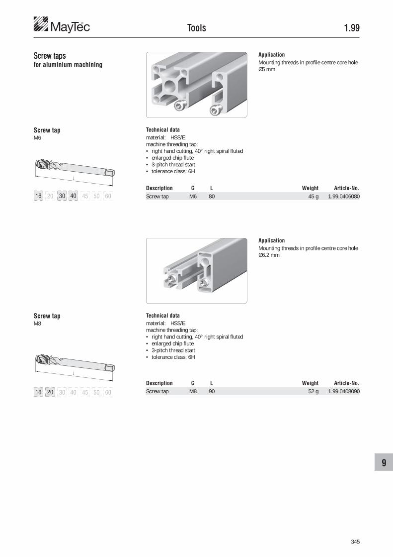
345
9
1.991.991.991.991.99
Screw tapsScrew tapsScrew tapsScrew tapsScrew tapsfor aluminium machining
ApplicationMounting threads in profile centre core holeØ5 mm
Screw tapM6
Screw tapM8
ApplicationMounting threads in profile centre core holeØ6.2 mm
Description G L Weight Article-No.Screw tap M6 80 45 g 1.99.0406080
Description G L Weight Article-No.Screw tap M8 90 52 g 1.99.0408090
Technical datamaterial: HSS/Emachine threading tap:• right hand cutting, 40° right spiral fluted• enlarged chip flute• 3-pitch thread start• tolerance class: 6H
Technical datamaterial: HSS/Emachine threading tap:• right hand cutting, 40° right spiral fluted• enlarged chip flute• 3-pitch thread start• tolerance class: 6H
TTTTToolsoolsoolsoolsools

346
1.991.991.991.991.99
Screw tapsScrew tapsScrew tapsScrew tapsScrew tapsfor aluminium machining
ApplicationFastening thread in hollow chambers ofprofiles PG 50
Screw tapM12
Screw tapM14
ApplicationMounting threads in profile centre core holeØ12 mm
Description G L Weight Article-No.Screw tap M12 110 65 g 1.99.0412110
Description G L Weight Article-No.Screw tap M14 110 75 g 1.99.0414110Screw tap M14 150 105 g 1.99.0414150
Technical datamaterial: HSS/Emachine threading tap:• right hand cutting, 40° right spiral fluted• enlarged chip flute• 2-pitch thread start• tolerance class: 6H
Technical datamaterial: HSS/Emachine threading tap:• right hand cutting, 40° right spiral fluted• enlarged chip flute• 2-pitch thread start• tolerance class: 6H
TTTTToolsoolsoolsoolsools

347
19" profiles .................................................................................. 57
AAbbreviations ................................................................................ 5Accessories ............................................................................... 139Acrylic ....................................................................................... 333Additional accessories ..................................................... 140, 234Adjustable tilt-feet ..................................................................... 184
anti-slip discs ..................................................................... 188cushion elements ................................................................ 188nuts .................................................................................... 187plates .................................................................................. 185Single parts ........................................................................ 184spindles .............................................................................. 187
Adjustable tilt-foot anti-slip discs ............................................. 188Adjustable tilt-foot cushion elements ........................................ 188Adjustable tilt-foot nuts ............................................................. 187
Stainless steel ..................................................................... 187Steel .................................................................................... 187
Adjustable tilt-foot plates .......................................................... 185with mounting holes ........................................................... 186without mounting holes ...................................................... 185
Adjustable tilt-foot plates with mounting holes ......................... 186GD-Zn ................................................................................. 186PA ....................................................................................... 186Stainless steel ..................................................................... 186
Adjustable tilt-foot plates without mounting holes ................... 185GD-Zn ................................................................................. 185PA ....................................................................................... 185Stainless steel ..................................................................... 185
Adjustable tilt-foot spindles ...................................................... 187Stainless steel ..................................................................... 187Steel .................................................................................... 187
Alu hinges ................................................................................. 251heavy .................................................................................. 253Press-fit pins for alu hinges ............................................... 252Spacer ................................................................................ 252Type A ................................................................................. 251Type B ................................................................................. 251Type C ................................................................................. 252
Alu hinges, heavy ...................................................................... 253Alu-plastic composite panel ...................................................... 333Angle profiles .............................................................................. 53Angles ....................................................................................... 201
Angles 25×40 ...................................................................... 201Angles Alu ........................................................................... 210Angles GD-Al ...................................................................... 209Angles GD-Zn ..................................................................... 203Angles PA ........................................................................... 202Swivel angles ...................................................................... 211
Angular adjusting feet ............................................................... 189with adjusting screw ........................................................... 189without adjusting screw...................................................... 189
Angular tolerance ........................................................................ 68Anti-twist devices ...................................................................... 135
for subsequent insertion ..................................................... 136Approximate determination of deflection .................................... 69
BBar locks ................................................................................... 279
Assembly accessories ........................................................ 281Lock mounting sets ............................................................ 282Olive installation sets .......................................................... 282Profile machining ................................................................ 280
Subject indexSubject indexSubject indexSubject indexSubject index
Base angle ................................................................................. 196Base feet ........................................................................... 190, 191
Floor mounting sets ................................................... 190, 194Profile mounting sets ......................................................... 195
Base plates ................................................................................ 213with thread .......................................................................... 214without thread .................................................................... 214
Base profiles ............................................................................... 52Bayonet type connector ............................................................ 119Bending strength ......................................................................... 68Block for cable binder ............................................................... 309Bores for parallel-connector ........................................................ 62Bullet catches ............................................................................ 267
PA ....................................................................................... 268Button head screws ................................................................... 338
CCable and hose clamp ............................................................... 308Cable binder .............................................................................. 309
detachable .......................................................................... 309Calculation formulas for polygons ............................................ 130Carabine swivel ......................................................................... 305Castors ...................................................................................... 197
Fixed castors ...................................................................... 197Fixed castors with bolt hole ................................................ 197Fixed castors with fitting plate ............................................ 197Locking castors .................................................................. 199Swivel castors .................................................................... 198Swivel castors lockable ...................................................... 198Swivel castors lockable with bolt hole ................................ 198Swivel castors lockable with fitting plate ............................ 198Swivel castors with bolt hole .............................................. 198Swivel castors with fitting plate .......................................... 198Threaded bolt for locking castor with center thread ........... 200
Chipboards ................................................................................ 332Clamping connector .................................................................. 123Clamping for guidance system .................................................. 298Clamping levers ......................................................................... 137Coding examples ......................................................................... 64
for price group 1 ................................................................... 64for price group 2 ................................................................... 65for price group 3 ................................................................... 66
Combination profiles .................................................................160PVC ............................................................................ 159, 162
Connection ................................................................................ 134elements .............................................................................134of 0-slot profiles .................................................................124of MayTec with other profile systems ................................. 132of profiles 40, round ........................................................... 130plates .................................................................................. 217with corner pieces .............................................................. 222
Connection elements .................................................................134Anti-twist devices ............................................................... 135Anti-twist devices for subsequent insertion ....................... 136Clamping levers .................................................................. 137Retaining plates .................................................................. 134
Connection plates ...................................................................... 217Connection possibilities ............................................................ 124
for 0-slot profiles ................................................................ 124for profiles 40, round .......................................................... 130Other profile systems ......................................................... 132Special cases ...................................................................... 131Subsequent mounting of profiles ....................................... 131
348
Subject indexSubject indexSubject indexSubject indexSubject index
Connection possibilities for 0-slot profiles ............................... 124Connection with DIN-Screw ................................................ 129Connection with screw-type connector .............................. 128Connection with standard connector .................................. 125
Connection possibilities for profiles 40, round ......................... 130Calculation formulas for polygons ...................................... 130
Connection System ..................................................................... 85Connection variants with screw-type connectors .............. 95, 100Connector .................................................................................... 94
Bayonet type connector ...................................................... 119Clamping connector ............................................................ 123Connector screw ................................................................. 101Connector screw-self-cutting ............................................. 101Cross connector ................................................................. 121Extension ....................................................................... 94, 98Extension / parallel connector ............................................ 111Miter 90°-bent anchor l ........................................................ 99Miter 90°-bent anchor r ........................................................ 99Miter 90°-hinge l + r ...................................................... 94, 99Miter-bent anchor l + r .......................................................... 99Miter-hinge l + r ............................................................. 94, 99Oblique 90°-bent anchor ...................................................... 97Oblique 90°-bent anchor 90° ................................................97Oblique 90°-hinge .......................................................... 94, 97Oblique-bent anchor l ........................................................... 96Oblique-bent anchor r ........................................................... 97Oblique-bent anchor standard l ............................................ 97Oblique-bent anchor standard r ............................................ 97Oblique-cross-hinge ............................................................. 97Oblique-cross-hinge 90° ...................................................... 97Oblique-hinge l + r ......................................................... 94, 96Parallel connector for subsequent insertion ....................... 122Parallel-cross ................................................................. 94, 98Parallel-high ................................................................... 94, 98Parallel-high 90° ................................................................... 98Parallel-square ............................................................... 94, 98Parallel-square 90° ............................................................... 98Screw-type front sided ................................................ 95, 100Screw-type parallel-cross ............................................ 95, 100Screw-type parallel-high .............................................. 95, 100Screw-type parallel-square .......................................... 95, 100SE-Connector ..................................................................... 113Shifter ................................................................................... 99Square head Standard .......................................................... 96Square head Standard 90° ....................................................96Square head Universal .......................................................... 96Standard ............................................................................... 96Standard 90° ........................................................................ 96ST-Connector ...................................................................... 114ST-Connector with anchor, screw-type ............................... 115Universal ........................................................................ 94, 96Universal connector with knurled cross bushing ............... 112
Connector - Cross bushings ...................................................... 102Drill dimensions for connector cross bushings .................. 102Mounting variants ............................................................... 103
Connector - Drill dimensions .................................................... 124with radius covers .............................................................. 124without radius covers ......................................................... 124
Connector complete .................................................................. 105PG 20 ................................................................. 105, 106, 108PG 30 ......................................................................... 106, 108PG 40 ......................................................................... 106, 108PG 45 ......................................................................... 107, 109PG 50 ......................................................................... 107, 109PG 60 ......................................................................... 107, 109
Connector components ............................................................. 105Anchor ....................................................................... 105, 107Cross bushing ............................................................ 105, 106Setscrew ............................................................................. 107Spring ................................................................................. 107
Connector for ............................................................................ 105core hole-Ø 12 mm ............................................................. 106core hole-Ø 6 mm ............................................................... 105
Connector kits ........................................................................... 117Parallel ................................................................................ 118Standard ............................................................................. 117
Connector screw self-cutting .................................................... 116Connector selection .................................................................... 93Connectors .................................................................................. 92
Connector complete ........................................................... 105Cross bushings ................................................................... 102drill dimensions .................................................................. 124Examples .............................................................................. 87Machining of profiles with core hole-Ø12 ............................ 96Machining of profiles with core hole-Ø6 .............................. 94Manufacture a connection .................................................... 92Parallel connector ............................................................... 110Special cases ............................................................... 93, 110types and materials .............................................................. 93
Connectors - Special cases ....................................................... 110Bayonet type connector ...................................................... 119Clamping connector ............................................................ 123Connector kits .................................................................... 117Connector screw self-cutting .............................................. 116Cross connector ................................................................. 121Extension / parallel connector ............................................ 111Parallel connector for subsequent insertion ....................... 122SE-Connector ..................................................................... 113ST-Connector ...................................................................... 114ST-Connector with anchor, screw-type ............................... 115Universal connector with knurled cross bushing ............... 112
Corner elements ........................................................................ 328Corner element 33 for wire net mounting profile 33×10 ....329for wire net mounting profile .............................................. 328
Corner pieces ............................................................................ 22045° ...................................................................................... 221cubic .......................................................................... 220, 223segment .............................................................................. 223segment, 2gang .................................................................. 223spherical .................................................................... 221, 223
Cover caps ................................................................................ 173for profiles with core hole-Ø12 ........................................... 174for profiles with core hole-Ø6 ............................................. 173for profiles without core hole ............................................. 173for screw bores ................................................................... 177for tube profile .................................................................... 175for tubes ............................................................................. 177Ø48 for hand rail profile ..................................................... 175
Cover plug ........................................................................ 124, 176domed................................................................................. 176for connector bushings ...................................................... 176
Cover profiles ............................................................................ 157Alu ...................................................................................... 157PVC ..................................................................................... 157
Cross bore ................................................................................... 62Cross bushing ........................................................................... 102
bore for connector ................................................................ 62Cross connection plates ............................................................ 212Cross connector ........................................................................ 121Cross section of slots .................................................................... 6

349
Subject indexSubject indexSubject indexSubject indexSubject index
Cross-blocks for cable binder ................................................... 309C-track ......................................................................................... 54Curved profiles ............................................................................ 84Cylinder locks ............................................................................ 271
flush .................................................................................... 273with security latch .............................................................. 272
DDeflection .................................................................................... 69Delivery length ............................................................................ 67Determination of deflection ......................................................... 69Direction and Position ................................................................. 63Distance washer ........................................................................ 299Door handle ............................................................................... 278Door knob ................................................................................. 278Double hinge ............................................................................. 245Drill dimensions for connector cross bushings ........................ 102Drill jigs ..................................................................................... 340
for profiles with F- and E-slots ........................................... 342for profiles with H-slots ...................................................... 340with clamping lever ................................................... 340, 342with setscrew ............................................................. 340, 342
Drills ................................................................................. 341, 343
EE3-slot ........................................................................................... 6E4-slot ........................................................................................... 6Eco-Slides ................................................................................. 300Edge roller ................................................................................. 291Electrical accessories ....................................................... 141, 306Electrical installation trunking .......................................... 320, 324
accessories ......................................................................... 320E-trunking Alu, base profiles ....................................... 58, 324E-trunking Alu, end plates .................................................. 326E-trunking Alu, for clips ...................................................... 327E-trunking Alu, lids ...................................................... 58, 325E-trunking Alu, pre-cut lid .................................................. 325
E-trunking Alu .................................................................. 320, 324E-trunking Alu, end plates .................................................. 326E-trunking Alu, for clips ...................................................... 327E-trunking Alu, pre-cut lid .................................................. 325
E-trunking profiles ...................................................................... 58Base profiles ......................................................................... 58Cover profiles ....................................................................... 58
Extension / parallel connector ................................................... 111Extruded profile as per DIN EN 12020 ........................................ 67Eye-bolt ..................................................................................... 219
FFastening elements ................................................................... 139Fastening plate 30×150 ............................................................. 218Fixed castors ............................................................................. 197
with bolt hole ...................................................................... 197with fitting plate .................................................................. 197
Flap-lock countersunk ............................................................... 273Flatness of profile surfaces ......................................................... 67Flatness tolerance ....................................................................... 67Flexure load ............................................................................... 133Floor levelling screw ................................................................. 181Floor mounting plate ................................................................. 215Floor plate ................................................................................. 216Framing profiles ............................................................... 164, 169
one piece ............................................................................ 164two pieces ........................................................................... 169
F-slot ............................................................................................. 6Functional length ......................................................................... 67
GGrab handle profiles ........................................................... 53, 238Grab handles .............................................................................238Grid, steel .................................................................................. 335Ground connections .................................................................. 307Ground connector for potential equilisation .............................. 306Guard locking device .................................................................313Guidance system ....................................................................... 297
Clamping for guidance system ........................................... 298Distance washer .................................................................299Sliding blocks ..................................................................... 298T-Nut sliding blocks ............................................................ 299
Guide profile PVC ...................................................................... 163
HHand adjustable feet .................................................................. 182Hand rail ...................................................................................... 78Handle system ........................................................................... 236
oval design ......................................................................... 237round design ....................................................................... 236
Handles ..................................................................................... 234light Alu .............................................................................. 234light PA ............................................................................... 234PA ....................................................................................... 235PA with bore ....................................................................... 235PA with thread .................................................................... 235
Hanging bracket ........................................................................ 304Hinge profiles .............................................................................. 55
1.5 mm ................................................................................. 552.0 mm ................................................................................. 553.0 mm ................................................................................. 565.0 mm ................................................................................. 55
Hinges ...................................................................... 239, 244, 246Alu hinges ........................................................................... 251Alu hinges, heavy ................................................................ 253Double hinge ....................................................................... 245Lift-off hinges ..................................................................... 240
Hollow profiles ............................................................................ 52
IIndex .........................................................................................347Installation accessories .................................................... 139, 157Installation rings ....................................................................... 310
JJoints ........................................................................................ 255
with / without clamping lever ............................................. 257with clamping lever ............................................................ 255without clamping lever ....................................................... 255Zn ....................................................................................... 257Zn, with clamping lever ...................................................... 257Zn, without clamping lever ................................................. 257
LLatch lock .................................................................................. 283Levelling feet .................................................................... 181, 183Levelling furniture foot .............................................................. 183Lift-off hinges ............................................................................ 240Lock GD-Zn ............................................................................... 270Lock mounting set .................................................................... 282
with double beard key .........................................................282with square key ...................................................................282

350
Subject indexSubject indexSubject indexSubject indexSubject index
Locking castors ......................................................................... 199with center thread ............................................................... 200with plate ............................................................................ 199
MMachining of profiles .................................................................. 94
with core hole-Ø12 ............................................................... 96with core hole-Ø6 ................................................................. 94with core hole-Ø6 for miter .................................................. 94
Magnetic lock PA ....................................................................... 269Makrolon ................................................................................... 334MayTec connector with square head ........................................... 87MayTec ground-connector for potential equilisation ................... 87MayTec screw-type connector .................................................... 87MayTec standard-connector ........................................................ 87MayTec universal-connector ....................................................... 87Mechanical data .......................................................................... 67Milling cutter .................................................................... 341, 343Mortise deadlocks ..................................................................... 275
cases .................................................................................. 276cases with lock ................................................................... 277cases without lock .............................................................. 276Door handle ........................................................................ 278Door knob ........................................................................... 278Installation sets .................................................................. 276Installation sets with lock ................................................... 277Installation sets without lock ..............................................276Profile machining ................................................................ 275Push pins ............................................................................ 278
Mounting adaptor for roller ....................................................... 290Mounting blocks ....................................................................... 258
Distancing plate, thin .......................................................... 261for subsequent insertion ..................................................... 260GD-Zn ................................................................................. 259screw-type .......................................................................... 258
Mounting clamp blocks ............................................................. 262for subsequent insertion ..................................................... 262SL ....................................................................................... 264Tool for mounting clamp block SL ...................................... 264
Mounting instruction for screw-type connectors ............... 95, 100Mounting of connector in core hole ............................................ 88Mounting of connector in slot ..................................................... 89Mounting plates ........................................................................ 216Mounting set for 19" profile ...................................................... 311Mounting sockets ...................................................................... 330Mounting variation .................................................................... 125
for high flexure load ........................................................... 126for high sliding load ............................................................ 127for profiles with 1 connector .............................................. 125
NNumerical key for articles ............................................................. 7
OOlive installation sets ................................................................ 282Order description ........................................................................ 60Order examples for special design .............................................. 66Oval tube ................................................................................... 237
PPanel elements ......................................................... 141, 328, 331
Acrylic ................................................................................. 333Alu-plastic composite panel ............................................... 333Chipboards ......................................................................... 332Grid, steel ........................................................................... 335Makrolon ............................................................................ 334
Polycarbonate ..................................................................... 334Solid plastic panels ............................................................. 332Wire net, Alu ....................................................................... 334Wire net, steel ..................................................................... 335
Panel framing profile ................................................................... 54Panel profiles .............................................................................. 45
Panel profiles 30, F-slot, P ................................................... 45Panel profiles 40, E3-slot, P ................................................. 46Panel profiles 50, E4-slot, P ................................................. 47
Parallel connector ..................................................................... 110Parallel connector for subsequent insertion .............................122Parallelism tolerance ................................................................... 68Pneumatic ................................................................................. 224
90° connection sets ............................................................ 232accessories ......................................................................... 224connection plate sets .......................................................... 230connection plates ............................................................... 230end plate sets ..................................................................... 225end plates ........................................................................... 225extension sets ..................................................................... 231
Pneumatic accessories ............................................. 140, 224, 233Blanking plug ...................................................................... 233Reducing nipple .................................................................. 233Sealing ring ......................................................................... 233
Polycarbonate ........................................................................... 334Potential equalisation ................................................................ 306Press in device for knurled cross bushing ................................ 338Press-fit pins for alu hinges ...................................................... 252Press-fit threaded inserts .......................................................... 155
without collar ...................................................................... 156Price groups (1 -3) ...................................................................... 61Profile applications ...................................................................... 74
Curved profiles ..................................................................... 84Hand rail ............................................................................... 78Profile combinations ............................................................. 74Profiles for cable guide ......................................................... 80Slot plates ............................................................................. 75Special slits .......................................................................... 74U-Profile 40 .......................................................................... 79
Profile combinations ................................................................... 74Profile group ............................................................................... 12
16 mm, E3-slot, P ................................................................. 1216 mm, F-slot, P ................................................................... 1220 mm, F-slot, P ................................................................... 1520 mm, H-slot, P .................................................................. 1330 mm, E4-slot, P ................................................................. 1830 mm, F-slot ....................................................................... 3430 mm, F-slot, P ................................................................... 1640 mm, E3-slot ..................................................................... 3640 mm, E3-slot, P ................................................................. 2045 mm, E4-slot ..................................................................... 4045 mm, E4-slot, P ................................................................. 2850 mm, E4-slot ..................................................................... 4250 mm, E4-slot, P ................................................................. 3160 mm, E4-slot ..................................................................... 4460 mm, E4-slot, P ................................................................. 32
Profile machining ........................................................................ 60Bores for parallel-connector ................................................. 62Coding examples .................................................................. 64Coding examples for special design ..................................... 66Cross bore ............................................................................ 62Cross bushing bore for connector ........................................ 62Direction and Position .......................................................... 63Order description .................................................................. 60Price group 1-3 ..................................................................... 61Saw cut ................................................................................. 61
351
Subject indexSubject indexSubject indexSubject indexSubject index
Saw cut tolerance ................................................................. 61Summary .............................................................................. 60Thread .................................................................................. 62
Profile pre-cut lids ....................................................................... 52lid 120 ................................................................................. 325lid 30 ..................................................................................... 81lid 40 ..................................................................................... 82lid 50 ..................................................................................... 83
Profile selection range ................................................................. 70Profile tolerance .......................................................................... 67Profiles 48, round (plain) ............................................................ 33Profiles for cable guide ............................................................... 80
Slot distance 30 .................................................................... 81Slot distance 40 .................................................................... 82Slot distance 50 .................................................................... 83
Profiles for pneumatic applications ........................................... 224Profiles hexagonal (plain) ........................................................... 33Profiles octagonal (plain) ............................................................ 33Push pins .................................................................................. 278
QQuick locks ................................................................................ 265
RRadius compensations .............................................................. 180Radius covers ........................................................................... 178
Rectangle 90° with one radius ............................................ 179Rectangle 90° with two radii ............................................... 179Rectangle with one radius .................................................. 178Rectangle with two radii ..................................................... 179Square with one radius ....................................................... 178Square with two radii .......................................................... 179
Reducing profiles PVC .............................................................. 158Register ......................................................................................... 1Retaining plates ......................................................................... 134Rhomboid T-slot nuts ............................................................... 151Roller 29 .................................................................................... 285Roller 39 .................................................................................... 284Roller fastening sets ................................................................. 286
A, double sided ................................................................... 287A,one sided ......................................................................... 287type A ................................................................................. 286type B ................................................................................. 288
Roller fitting .............................................................................. 292Roller profiles (plain) .................................................................. 50Rubber cover-profiles ............................................................... 172Runner ...................................................................................... 293
for sliding suspended doors ............................................... 294for suspended doors .......................................................... 293Stopper Type 1 for sliding suspended doors ...................... 295Stopper Type 2 for sliding suspended doors ...................... 295
SSafety interlocking .................................................................... 314
Contact bracket-mounting .................................................. 315mountings .......................................................................... 314
Safety interlocking-mountings .................................................. 314AZ 17 for sliding door ......................................................... 317AZ 17 for swinging door ..................................................... 316for sliding door ................................................................... 315for swinging door ............................................................... 314with lock for swinging door ................................................ 314
Safety switches ......................................................................... 312AZ 17 .................................................................................. 313Contact bracket-mounting .................................................. 315Guard locking devices AZM 170 .........................................313
Saw cut ....................................................................................... 61Saw cut tolerance ........................................................................ 61Screw taps ................................................................................ 345Screw taps for aluminium machining ........................................ 345Screws ...................................................................................... 338
Button head screws ............................................................ 338Sealing profile ........................................................................... 168SE-Connector ............................................................................ 113Security latch ............................................................................ 272Self locking washers .................................................................336
SP ....................................................................................... 337Standard .............................................................................337
Sensor brackets ........................................................................ 319Slide load .................................................................................. 133Slide-slot profiles PA ................................................................... 57Sliding blocks ............................................................................ 298Sliding doors .............................................................................161
construction types .............................................................. 161Sliding profiles ............................................................................ 54Slot plates ................................................................................... 75
E-slot .................................................................................... 75E-slot, slot distance 25 mm .................................................. 77E-slot, slot distance 50 mm .................................................. 77F-slot .................................................................................... 75F-slot, slot distance 25 mm .................................................. 76F-slot, slot distance 50 mm .................................................. 76Profile 30×100, 10F, SP ........................................................ 76Profile 30×100, 5E, 2F, SP .................................................... 77Profile 30×100, 9F, SP .......................................................... 76Profile 30×150, 8E, SP .......................................................... 77Profile 30×150, 8F, SP .......................................................... 76
Slot rollers ................................................................................. 296Slot system ................................................................................... 6
E3-slot .................................................................................... 6E4-slot .................................................................................... 6F-slot ...................................................................................... 6H-slot ...................................................................................... 6
Solid plastic panels ................................................................... 332Spacer ....................................................................................... 252Special cases ............................................................................... 93Special characters ......................................................................... 5Special profiles ..................................................................... 33, 52
19" profiles ...........................................................................57Angle profiles ........................................................................ 53Base profiles ......................................................................... 52C-track .................................................................................. 54E-trunking profiles ................................................................ 58Grab handle profiles ............................................................. 53Hinge profiles ................................................................ 55, 56Hollow profiles ...................................................................... 52Panel framing profile ............................................................ 54Profile pre-cut lids ................................................................ 52Profiles 48, round, P ............................................................. 33Profiles hexagonal, P ............................................................ 33Profiles octagonal, P ............................................................. 33Roller profiles, P ................................................................... 50Slide-slot profiles ................................................................. 57Sliding profiles ...................................................................... 54Telescopic profiles, E3-slot, P .............................................. 51T-Slot profiles ....................................................................... 56Tube profiles 30, P ................................................................ 49Tubes .................................................................................... 55U-profiles .............................................................................. 54Wire net mounting profiles ................................................... 53
Special slits ................................................................................. 74Sponge rubber round cords ...................................................... 166

352
ImprintSubject to technical modification.All rights reserved.Copying - also in parts - only allowed bywritten consent.© MayTec Aluminium Systemtechnik GmbH,Germany, D - 85221 Dachau, 2011
Subject indexSubject indexSubject indexSubject indexSubject index
Spring-nuts ............................................................................... 149Stacking foot ............................................................................. 196ST-Connector ............................................................................ 114
with anchor, screw-type ..................................................... 115Straightness tolerance ................................................................ 67Strength values for profile connections .................................... 133
with MayTec-Connectors .................................................... 133Subject index ............................................................................. 347Subsequent mounting of profiles .............................................. 131Summary ................................................................ 8, 88, 139, 339
Accessories ........................................................................ 139Connectors (with machining) ............................................... 88Connectors (without machining) .......................................... 90Profiles (plain) ........................................................................ 8Profiles (with grooves) ........................................................... 9Special profiles ..................................................................... 11Special profiles (plain) .......................................................... 10Tools ................................................................................... 339
Suspended doors ...................................................................... 292Alu C-track .......................................................................... 292Bottom guide ...................................................................... 293Frame guide ........................................................................ 293Roller fitting ........................................................................ 292Rubber door stop ............................................................... 293Runner ................................................................................ 293Stopper ............................................................................... 293
Suspended glider ...................................................................... 305Swivel angles ............................................................................ 211Swivel castors ........................................................................... 198Swivel castors lockable ............................................................. 198Symbols ........................................................................................ 5
TTable of contents ........................................................................... 2T-Bolts ....................................................................................... 152Technical data .............................................................................. 67
Angular tolerance .................................................................. 68Approximate determination of deflection ............................. 69Bending strength .................................................................. 68Deflection ............................................................................. 69Delivery length ...................................................................... 67Extruded profile as per EN 12020 ......................................... 67Flatness of profile surfaces .................................................. 67Flatness tolerance ................................................................. 67Functional length .................................................................. 67Mechanical data .................................................................... 67Parallelism tolerance ............................................................ 68Profile tolerance ................................................................... 67Straightness tolerance .......................................................... 67Twist tolerance ...................................................................... 67
Telescopic profiles (plain) ........................................................... 51Tension load .............................................................................. 133Thread ......................................................................................... 62Threaded bolt for locking castor with center thread ................. 200Threaded inserts ....................................................................... 153
Press-fit threaded inserts ................................................... 155Press-fit threaded inserts w/o collar .................................. 156
Threaded plates ......................................................................... 142for subsequent insertion ..................................................... 143heavy .................................................................................. 144
T-Nut sliding blocks .................................................................. 299T-Nuts ....................................................................................... 145
for subsequent insertion ..................................................... 146for subsequent insertion, with spring ................................. 147for subsequent insertion, with spring ball ..........................146for subsequent insertion, with spring, 2×M4 ...................... 148
for subsequent insertion, with spring, 2×M8...................... 147with spring .......................................................................... 145
Tools ................................................................................. 141, 339Drill ............................................................................ 341, 343Drill jigs ..................................................................... 340, 342for anchors ......................................................................... 339for cross bushings .............................................................. 339for profiles with F- and E-slots ........................................... 343for profiles with H-slots ...................................................... 341Milling cutter ............................................................. 341, 343Press in device for knurled cross bushings ........................ 338Screw taps .......................................................................... 345Special cases ...................................................................... 344Summary ............................................................................ 339Tx screw driver ................................................................... 338
Torque tightening values for connector setscrew ..................... 133Torx ........................................................................................... 338T-slot nuts ................................................................................. 150T-slot profiles .............................................................................. 56
PA ......................................................................................... 56Steel ...................................................................................... 56
Tube profiles ................................................................................ 49Tubes ........................................................................................... 55Twin track guide for roller 29 .................................................... 285Twist tolerance ............................................................................ 67Tx screw driver .......................................................................... 338Type of load ................................................................................. 68
UUniversal connector ............................................................. 94, 96
for profile 30×150 ............................................................... 110with knurled cross bushing ................................................ 112
U-Profile 40 ................................................................................. 79U-Profiles .................................................................................... 54
VVibration proof ............................................................................ 85
WWashers .................................................................................... 336Wedge profiles .......................................................................... 165Wire net mounting profiles ......................................................... 53Wire net profiles .......................................................................... 48
30, F-slot, P .......................................................................... 4840, F / E3-slot, P ................................................................... 48
Wire net, Alu .............................................................................. 334Wire net, steel ........................................................................... 335

MayTec GmbH plant in Dachau
Stock of aluminium profiles
Small partsstorage

The key...
AustraliaGermany
USAMayTec AluminiumSystemtechnik GmbHKopernikusstraße 20D - 85221 Dachau
country code: +49phone (0) 8131 / 33 36 - 0fax (0) 8131 / 33 36 - 119e-mail: [email protected]://www.maytec.de
MayTec Inc.901 Wesemann DriveWest Dundee, IL 60118
country code: +1phone 847 - 429 - 0321fax 847 - 429 - 0460e-mail: [email protected]://www.maytecinc.com
MayTec Australia P/LUnit 1, 8 Prosperity ParadeWarriewood, NSW 2102
country code: +61phone (0) 2 / 9999 0890fax (0) 2 / 9979 8703e-mail: [email protected]://www.maytec.com.au
to success
VK
-E12
/1.0
-011
1
extremestrong
dependable
Your professional partner