Embed Size (px)
Citation preview
R
Dry-head Type, High-speed, Computer-controlled, Single Thread,Chainstich Button Sewing Machine(with Automatic Thread Trimmer and Knot-tying Mechanism)
MB-1800MB-1800A
ENGINEER’S MANUAL
29345105No.00

PREFACE
This Engineer’s Manual is written for the technical personnel who are responsible for the service and maintenance
of the machine.
The Instruction Manual for these machines intended for the maintenance personnel and operators at an apparel
factory contains operating instructions in detail. And this manual describes “Standard Adjustment”, “Adjustment
Procedures”, “Results of Improper Adjutment”, and other important information which are not covered by the
Instruction Manual. It is advisable to use the revevant Instruction Manual and Parts List together with this
Engineer’s Manual when carrying out the maintenance of these machines.

CONTENTS
1. SPECIFICATIONS ................................................................................................................................... 1
2. NAME OF EACH COMPONENT ....................................................................................................... ......2(1) Name of the main unit ....................................................................................................... .......................................... 2
3. OPERATION OF THE SEWING MACHINE ............................................................................................ 3(1) Names of the operation panel switches ....................................................................................... ............................. 3
(2) Pattern table ............................................................................................................... .................................................. 4(3) How to operate and use the memory switch (User level) ....................................................................... ................. 5
4. STANDARD ADJUSTMENT .......................................................................................................... ......... 6(1) Height of the needle bar .................................................................................................... .......................................... 6(2) Positioning the needle and the looper....................................................................................... ................................ 6
(3) Timing the travel of the yoke slide ......................................................................................... .................................... 8
(4) Timing of the tension disc No. 2 ............................................................................................ .................................... 8(5) Lift and pressure of the button clamp ....................................................................................... .............................. 10
5. ADJUSTMENT OF THE THREAD TRIMMING MECHANISM ..............................................................10(1) The mechanism and the name of each component of the thread trimmer .......................................................... 10(2) Adjusting the position of the moving knife .................................................................................. ........................... 12
(3) Adjusting the height of the thread separating claw of the moving knife ...................................................... ....... 12
6. PROCEDURES IN DISASSEMBLING AND ASSEMBLING ................................................................14(1) Name of each component ...................................................................................................... ................................... 14
(2) Disassembling the circuit board ............................................................................................. ................................. 16(3) Disassembling the machine arm and bed ....................................................................................... ........................ 18
(4) Disassembling the looper shaft .............................................................................................. ................................. 20
(5) Disassembling the driving shaft ............................................................................................. ................................. 22
7. ADJUSTMENT OF THE SENSORS.................................................................................................... .. 26(1) Adjusting the starting sensor ............................................................................................... .................................... 26
(2) Adjusting the presser lifter sensor ......................................................................................... ................................. 26(3) Adjusting the feed origin sensor ............................................................................................ ................................. 28
(4) Adjusting the presser lifter stopper ........................................................................................ ................................. 28
8. HOW TO OPERATE AND USE THE MEMORY SWITCH (SERVICE LEVEL) .................................... 30(1) Memory switch function table ................................................................................................ .................................. 31
9. HOW TO OPERATE AND USE THE INPUT CHECK MODE FUNCTION ........................................... 33(1) INPUT CHECK CORRESPONDENCE TABLE ............................................................................................ .............. 34
10. HOW TO OPERATE AND USE THE ALL CLEAR FUNCTION ........................................................... 35
11. PARTS TO BE GREASESD ........................................................................................................ ..........36
12. ERROR LIST .........................................................................................................................................37
13. CHANGE-OVER OF THE POWER SOURCE VOLTAGE .................................................................... 38
14. CAUSE OF TROUBLES AND THE CORRECTIVE MEASURES......................................................... 39(1) Thread trimming troubles and the corrective measures ........................................................................ ............... 39
(2) Cause of troubles and the corrective measures for MB-1800 ................................................................... ............ 40
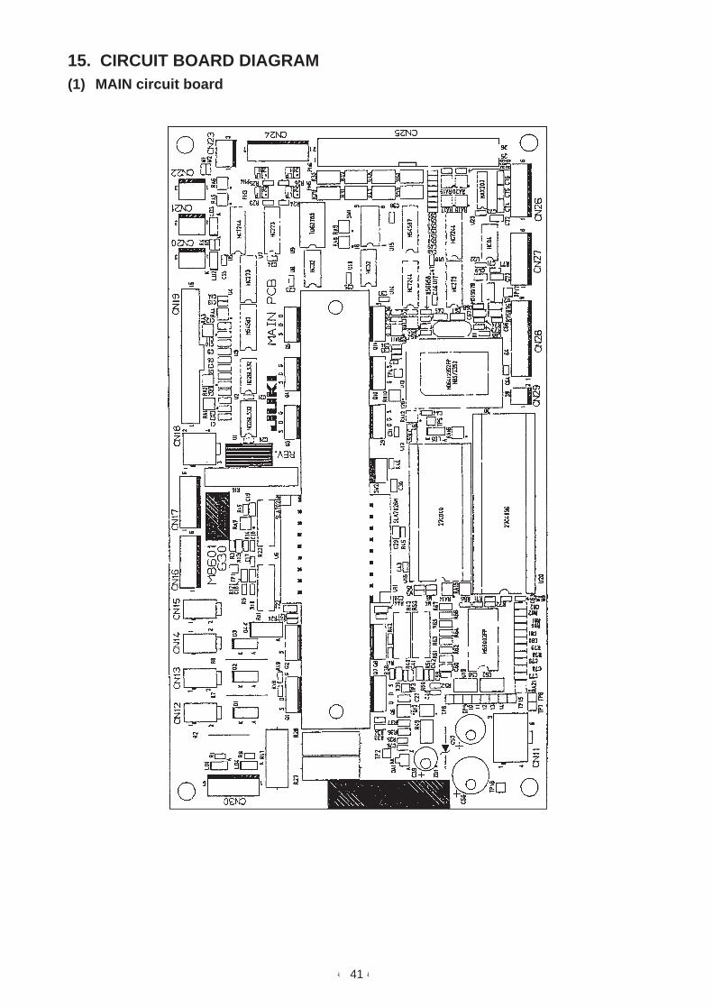
15. CIRCUIT BOARD DIAGRAM ....................................................................................................... .........41(1) MAIN circuit board .......................................................................................................... ........................................... 41
(2) PWR circuit board ........................................................................................................... .......................................... 42(3) PANEL circuit board ......................................................................................................... ......................................... 42
16. BLOCK DIAGRAM 1/2 ........................................................................................................... ............... 43
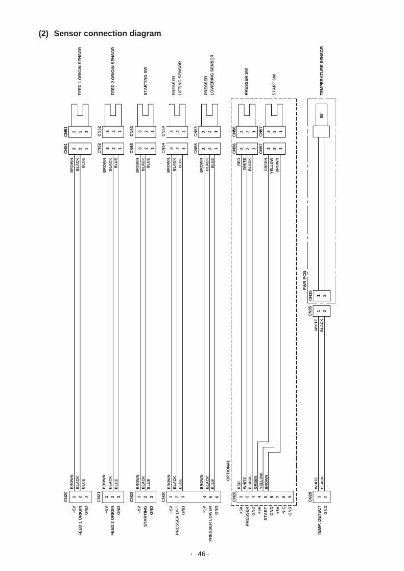
17. CONNECTION DIAGRAM AND CIRCUIT DIAGRAM .......................................................................... 45(1) Power connection diagram .................................................................................................... ................................... 45(2) Sensor connection diagram ................................................................................................... .................................. 46
(3) Motor circuit diagram ....................................................................................................... ......................................... 47(4) Encoder circuit diagram ..................................................................................................... ...................................... 48
(5) Solenoid circuit diagram .................................................................................................... ....................................... 48
18. DRAWING OF THE TABLE ........................................................................................................ ..........49

- 1 -
1. SPECIFICATIONS
1) Sewing area : X (lateral) direction 10 mm
Y (longitudinal) direction 6.5 mm (0.2 mm pitch)
2) Max. sewing speed : 1,800 rpm
3) Feed motion of button clamp : Intermittent feed (2-shaft drive by stepping motor)
4) Needle bar stroke : 48.6 mm
5) Needle : TQx7, TQx1 (TQx7 #16 at the time of delivery)
6) Button size : 10 to 28 mm
7) Lift of button clamp : Standard 10 mm Max. 14 mm
8) Memory of pattern data : EEP-ROM (32K byte)
9) Enlargement/reduction system : Increase/decrease of stitch length system
10) Limitation of sewing speed : Sewing speed can be optionally limited to 400 to 1,800 rpm with the
up/down key. (Adjustable in 100 rpm unit)
11) Pattern selection function : 1 to 99 patterns can be specified by selecting the pattern Nos.
12) Memory back-up : In case of a power interruption, the pattern being used will be
automatically stored in memory.
13) Sewing machine motor : 100W servo motor (direct-drive)
14) Dimensions of machine head : W : 240 mm L : 550 mm H : 360 mm
15) Mass : 25 kg
16) Power consumption : 150 W
17) Operating temperature range : 5 to 35˚C
18) Operating humidity range : 35 to 85% (no dew condensation)
19) Line voltage : Rated voltage ±10% 50/60 Hz
20) Noise : Workplace - related noise at sewing speed
n= 1,800 min-1 : LPA ≦ 80 dB(A)
Noise measurement according to DIN 45635-48-B-1.
* Reduce the max. sewing speed in accordance with the sewing conditions.

- 2 -
2. NAME OF EACH COMPONENT
(1) Name of the main unit
• Machine head
• Electricalcomponents
• Operation panel
• Thread stand
• Button tray
• Power switch
• Starting pedal

- 3 -
3. OPERATION OF THE SEWING MACHINE
(1) Names of the operation panel switches
1 Set ready switch
This switch is used when making the sewingmachine from setting status to sewingpossible status.
2 Button clamp lifting switch
This switch performs up/down of the buttonclamp.
3 Stitch shape selection LED
4 Stitch shape selection switch
This switch is used when changing the stitchshape.
5 + / Forward switch
This switch increases the set value or performstraveling forward when confirming the feed.
6 - / Backward switch
This switch decreases the set value or performstraveling backward when confirming the feed.
7 Item selection switch
This switch is used when selecting the itemdesired to be changed.
8 Item selection LED
9 Reset switch
This switch returns the various set valuesto the original status or performs releasewhen an error occurs.
!0 Display section A

- 4 -
(2) Pattern table
Three same sewing sizes and numbers of stitches for each stitch shape have been stored in pattern Nos. 1 to
51 at the time of delivery.
By selecting sewing size and number of stitches from the table below, the stitch shape can be changed to the
three different kinds of patterns of the same stitch shape and be stored in memory.
Pattern No.
123
456
789
101112
131415
161718
192021
222324
252627
282930
313233
343536
373839
404142
434445
464748
495051
4-holed( , crossover stitch : with)
4-holed( , crossover stitch : without)
4-holed( X, crossover stitch : with)
4-holed( X, crossover stitch : without)
4-holed( Z, crossover stitch : with)
2-holed (crosswise)
2-holed (lengthwise)
4-holed( , crossover stitch : with)
4-holed( , crossover stitch : without)
3-holed ( )
3-holed ( )
3-holed ( )
3-holed ( )
2-holed(crosswise) label attaching
Wrapped-around(crosswize size : 4 mm)
Wrapped-around(crosswise size : 5 mm)
Wrapped-around(crosswise size : 6 mm)
Initial value
2.6
2.6
2.6
2.6
2.6
2.6
2.6
2.6
2.6
2.6
2.6
2.6
2.6
10.0
2.6
2.6
2.6
Range
2.0 to 6.5
2.0 to 6.5
2.0 to 6.5
2.0 to 6.5
2.0 to 6.5
2.0 to 6.5
2.0 to 6.5
2.0 to 6.5
2.0 to 6.5
2.6, 2.8, 3.0
2.6, 2.8, 3.0
2.6, 2.8, 3.0
2.6, 2.8, 3.0
6.0, 8.0, 10.0
0.0 to 6.5
0.0 to 6.5
0.0 to 6.5
Unit
0.2
0.2
0.2
0.2
0.2
0.2
0.2
0.2
0.2
0.2
0.2
0.2
0.2
2.0
0.2
0.2
0.2
Initial value
15
16
15
16
15
8
8
15
16
17
17
17
17
5
16
16
16
Range
15, 19, 23, 27
16, 20, 24, 28
15, 19, 23, 27
16, 20, 24, 28
15, 19, 23, 27
8, 10, 12, 14
8, 10, 12, 14
15, 19, 23, 27
16, 20, 24, 28
17, 23
17, 23
17, 23
17, 23
5, 7
6, 10, 16
6, 10, 16
6, 10, 16
Stich size (mm) Number of stitchesStich shape

- 5 -
(3) How to operate and use the memory switch (User level)
1) The speed up to 3rd stitch can be set so that the sewing speed at the start of sewing is controlled and the
stitch is stabilized.
2) Effective/ineffective of the knot-tying functon can be selected.
3) Operating/non operating of the wiper can be selected.
In case the wiper is installed and set to the non-operating setting, when the pattern without crossover
thread is selected, the wiper works only when the crossover thread is trimmed, and it does not work after
thread trimming at the time of completion of sewing.
In case of the pattern with crossover thread as well, the wiper does not work after thread trimming at the
time of completion of sewing with this setting.
In case of the setting of operating the wiper, the wiper always works at the time of thread trimming.
1 Starting of the memory switches
In the state that +/- switches 2 are simultaneously
pressed, turn ON the power, and the memory switches
are in the state of setting.
At this time, “ ” is displayed in display section A 3.
Press set ready switch 5 and all 5 stitch shape
selection LEDs 9 flash on and off. This state means
that the memory switches are being inputted.
2 Setting procedure of the memory switches
There are the memory switches 1 to 8.
Switch N0. “ ” is displayed in the display section A 3 and item selection LED !0 of the pattern No.
lights up. In this state, press item selection switch 4, and the memory switch No. and the description
are alternately displayed in display section A 3.
In the state that the memory switch No. is displayed, press the + switch 8 and the memory switch No.
increases by one.
When the description of the memory switch is displayed, item selection LED !0 of the pattern No. goes
off.
When setting is completed, turn OFF the power. Return ON the power to return to the normal setting state.
Remarks
400 to 1,800 rpm
400 to 1,800 rpm
400 to 1,800 rpm
400 to 1,800 rpm
400 to 1,800 rpm
400 to 1,800 rpm
Switch No.
1
2
3
4
5
6
7
8
Description
Speed of 1st stitch of soft start
Speed of 2nd stitch of soft start
Speed of 3rd stitch of soft start
Speed of 1st stitch after trimming crossover thread
Speed of 2nd stitch after trimming crossover thread
Speed of 3rd stitch after trimming crossover thread
Knot-tying function 0 : Ineffective 1 : Effective
Wiper operation 0 : Non operating 1 : Operating
Initial setting
18* 100 [rpm]
18* 100 [rpm]
18* 100 [rpm]
18* 100 [rpm]
18* 100 [rpm]
18* 100 [rpm]
1 (Operating)
0 (Non operating)
Setting range
4 to 18
4 to 18
4 to 18
4 to 18
4 to 18
4 to 18
0.1
0.1
1
2
3
4
5
6
7
8
9
!0

- 6 -
(1) Height of the needle barThe upper engraved line of the two engraved lines for TQx1 and TQx7 should be aligned with the bottom of
the lower bushing when the needle bar is at its lowest position.
4. STANDARD ADJUSTMENT
(2) Positioning the needle and the looper
1) Looper timing
When the needle bar is ascending from its lowest
position and the lower engraved line on the needle
bar is aligned with the bottom of the lower bushing,
the looper’s blade point should coincide with the
center of the needle.
(When the needle bar is ascending.)
2) Clearance between the needle and looper
The clearance is 0.05 to 0.1 mm when the looper’s
blade point coincides with the center of the needle.
3) Clearance between the needle guide and needle
The clearance between the needle guide and
needle is 0.05 to 0.1 mm when the needle bar is at
its lowest position.
Height of the needle bar
For TQx1
For TQx1
Engraved line(upper engraved line)
Lowerbushing
Looper timing
Lower bushing
Engraved line
Looper’s bladepoint coincideswith center ofneedle.
Clearance between needle and looper
0.05 to 0.1 mm
Looper’s blade point
Clearance between needle guide and looper
Needle guide
0.05 to 0.1 mm
Screw
1
2
3
4
12
34
Standard Adjustment

- 7 -
™ If the needle bar is too high, skipped
stitches will be produced.
If the needle bar is too low, the needle
will come in contact with the looper.
1) Adjusting the looper timing
™ Loosen the two screws 3 in the looper and cam sleeve
and adjust in the rotating direction of the looper and
cam sleeve so that the looper’s blade point aligns with
the center of the needle when the lower engraved line
of the needle bar is aligned with the bottom of the lower
bushing. Then tighten the screws 3.
2) Clearance between the needle and looper
Loosen two screws 4 in the looper support ring and adjust
in the longitudinal position of the looper when the looper’s
blade point is aligned with the center of the needle. Then
tighten the screws 4.
3) Clearance between the needle guide and needle
Loosen the screw 2 in the needle guide 1 and adjust in
the longitudinal position of the needle guide 1 so that the
clearance between the needle guide 1 and needle should
become 0.05 to 0.1 mm when the needle bar is at its lowest
position. Then tighten the screw 2.
™ If the clearance between the needle
and looper is too excessive, it is likely
to produce skipped stitches. If the
clearance is too small, in accordance
with the material used, the needle will
come in contact with the looper
resulting in needle breakage and
looper’s blade point breakage.
™ For thick materials and overlapped
sections, adjust the clearance between
the needle guide and needle so that
the needle guide touches the needle
by 0.1 to 0.2 mm.
1) Slightly loosen knob 1 and turn cover 2 in the direction
of the arrow and you will find hand pulley 3.
2) Turn the hand pulley by hand, loosen setscrew 4 in the
needle bar thread-take up lever and adjust so that the
upper engraved line of the two engraved lines on the
needle bar aligns with the bottom of the lower bushing
when the needle bar is at its lowest position.
Adjustment Procedures Results of Improper Adjustment

- 8 -
(3) Timing the travel of the yoke slide
1) Crosswise travel timing of the yoke slide
The height of the descending needle bar is 53 to 58
mm when the yoke slide advances and begins to
travel from the right to the left (TQx7).
(In case of TQx1, 43 to 48 mm)
2) Lengthwise travel timing of the yoke slide
The yoke slide should go back immediately after
the blade point of the looper has passed the thread
triangle. And, it is good for the looper to go back
like a slant line of the movement of the triangle.
3) Lengthwise positioning of the yoke slide
Position the yoke slide so that the blade point of
the looper passes through the center of the thread
triangle.
(Use a 4-hole button, 9 or 10 stitches for positioning.)
(4) Timing of the tension disc No. 2The tension disc No. 2 should float when the height of ascending needle bar becomes 54 to 57 mm.
(In case of TQx1, 44 to 47 mm)
Needle bar
53 to
58
mm Advances and begins to
travel from right to left.
It is good forthe looper togo back likea slant line.
Yoke slide
(Begins to travel from right to left.)
Blade point of looper
54 to
57
mm
Begins to float
Screw driver
Needle bar
Standard Adjustment

- 9 -
™ For adjusting the timing of the travel of the yoke slide,
align the engraved marks of the loop positioning finger
cam and the triangle loop positionig finger cam with the
engraved mark of the cam and looper sleeve after
completing the adjustment of looper so that the engraved
marks are on a straight line. Then temporarily tighten the
screw.
1) Adjust the crosswise travel timing of the yoke slide in the
rotational direction of the triangle loop positioning finger
cam.
When the timing is higher than 58 mm (48 mm), adjust
the timing in the rotational direction of the cam.
And when it is lower than 53 mm (43 mm), adjust in the
reverse rotational direction.
The center of the cam is aligned with the center of the
yoke slide support in the longitudinal position of the cam.
2) Adjust the lengthwise travel timing of the yoke slide in the
rotational direction of the loop positioning finger cam.
For the triangle movement of the yoke slide, it is good for
the yoke slide to go back in a slant line. When the yoke
slide goes back like a swollen line, adjust the cam in the
reverse rotational direction, and when it goes back like a
hollow line inside, adjust the cam in the rotational direction.
3) Adjust the longitudinal position of the yoke slide by moving
the loop positioning finger cam in the lengthwise direction.
™ If the triangle loop positioning fingercam begins to travel too late, threadbreakage, thread remaining, baloonstitch, and insufficient tightness ofstitches will result. On the contrary, ifit begins to move too early, the needlewill come in contact with the yoke slide.
™ If the loop positioning finger cambegins to go back too early, the retreatof the yoke slide will become like aswollen line and the looper will hookthe thread twice.
™ On the other hand, if it begins to retreattoo late, its retreat will become like ahollow line and the needle will come incontact with the yoke slide.
™ If the longitudinal position of the yokeslide is improper, the looper will hookthe thread twice or the needle will comein contact with the yoke slide.
™ Loosen the adjusting nut of the tension post No. 2 and
insert a screwdriver into the tension post No. 2 to adjust
the timing.
The timing of the start of floating is when the thread
tension is lost after passing the thread through the thread
tension No. 2, holding it with fingers and turning the
handwheel by ha
™ If the thread tension is released too
early, thread remaining and/or poor
tightness of stitches will result.
On the other hand, if the timing of
thread tension release is too late,
thread will break.
Looper
Engraved points
Triangle looppositioningfinger cam Cam and looper sleeve
Loop positioning finger cam Yoko slide retreatslike a swollen line.
Yoko slide retreatslike a hollow line.
Screw driver
Timing of start of floatingis when thread tenshon islost at the time of needlebar ascending.
Nut
Adjustment Procedures Results of Improper Adjustment

- 10 -
(5) Lift and pressure of the button clamp
1) Lift of the button clamp
A Standard : 12 mm
Max. : 9 mm
2) Pressure of the button clamp
Adjust the position of the pressure adjusting nut to
4 to 5 mm.
4 to 5 mm
5. ADJUSTMENT OF THE THREAD TRIMMING MECHANISM
(1) The mechanism and the name of each component of the thread trimmer
Throat plate
Presser lifter solenoid
Thread trimming arm
Thread trimming lever
Presser lifter sensor
Presser lifter link
Presser lifter lever
1
2
3
A
1
2
Standard Adjustment

- 11 -
1) The knife moves in accordance with the lifting of the button
clamp. Therefore, the length of the remaining thread on
the wrong side of a fabric depends upon the height of the
button clamp at which the thread is trimmed.
For the adjustment, insert something of 10 mm thick into
section A and make a state that button clamp jaw levers
1 are lifted .
Loosen screw 2 and tighten screw 2 to fix the button
clamp in the state that lifting hook 3 is pressed to the
lower side.
2) Make adjustment by turning the pressure adjusting nut 1.
™ Increasing the lifting amount of the
button clamp will increase the length
of the remaining thread. Especially in
case of MB-372, thread tightness
becomes strong at the end of sewing
resulting in thread breakage and thread
slip-off.
™ If the lifting amount of the button clamp
is too low, the length of the remaining
thread will become short resulting in
thread slip-off.
™ If the pressure of the button clamp is
too low, the thread end at the start of
sewing will come out on the wrong side
of the fabric unevenly by 10 to 20 mm.
Adjustment Procedures Results of Improper Adjustment

- 12 -
(2) Adjusting the position of the moving knifeAdjust the position so that the distance between the thread trimming connecting plat (front) and the edge of
the slot in the throat plate should be 12 to 13 mm when the button clamp is at its highest position.
(3) Adjusting the height of the thread separating claw of the moving knifeMake adjustment so that the clearance between the thread separating claw 1 and the looper 2 should
become 0.5 to 0.7 mm.
0.5 to 0.7 mm
Top end of thread separation nail
1
2
3
4
5
6
7
8
9
1
2
Standard Adjustment

- 13 -
1) Remove cover 1 with setscrew 2.
2) In order to place thread trimming connecting plate A 9 to
the most advanced position, lift the presser lifter lever to
such an extent that roller 4 and hook 5 of presser lifter
lever 3 come in contact with each other and insert spanner
6 as shown in the figure on the left.
3) Insert gauge 7 into the end face of the throat plate groove,
loosen screws 8, make the top end of thread trimming
connecting plate A 9 come in contact with gauge 7, and
tighten screws 8.
™ If the thread separating claw is too high,
the claw may fail to separate the thread
on the needle from that on a fabric. As
a result, thread may not be trimmed,
or the both threads are trimmed
together, causing thread slippage from
the needle in the subsequent stitching
start.
™ If this dimension is excessively large,
the thread trimming timing is delayed
and the remaining thread on the wrong
side of cloth is lengthened.
If the dimension is excessively small,
the thread trimming timing becomes too
early, thread trimming failure such as
poor tightness of stitche (easily frayed)
at the last stitch, simultaneous thread
trimming of two threads due to the
failure of thread separation, no thread
trimming, etc. is apt to occur.
™ Make adjustment by bending the thread separating claw
1.
Adjustment Procedures Results of Improper Adjustment

- 14 -
6. PROCEDURES IN DISASSEMBLING AND ASSEMBLING
(1) Name of each component
Feed needle bearing
Needle bar upper bushing
Needle bar clamp
Needle bar lower bushing
Yoke slide
Triangle loop positioning finger cam
Looppositioningfinger cam
Needle bearing
Thrust bearing
Rocking rod fulcrum shaft
Screw gear
Crank rod hinge screw
Crank rod
Procedures in disassembling and assembling

- 15 -
Cautions in disassembling Cautions in assembling

- 16 -
(2) Disassembling the circuit board
1) Cover components
2) Circuit board components
Control box cover
Side cover
POWER circuit boardMAIN circuit board
POWER circuit board
Setscrew 1
MAIN circuit board
Setscrew 3
Circuit board installing plate
Collar
Setscrew 3
Setscrew 2
Procedures in disassembling and assembling

- 17 -
Disassembling and assembling of the circuit board
Disassembling
1) Remove the control box cover and the side cover.
Remove all connectors connected to the circuit board.
2) Loosen setscrews 1 by 2 to 3 mm.
3) Remove setscrews 2, hold the circuit board installing plate
by hand and draw it out in the direction of the arrow and
you can remove the circuit board in the state that it is
connected to the circuit board installing plate.
4) Remove 8 setscrews 3, and MAIN circuit board and
POWER circuit board can be removed.
Assembling
1) Assemble in the order of MAIN circuit
board, collar, circuit board installing
plate, collar and POWER circuit board.
Cautions in disassembling Cautions in assembling

- 18 -
(3) Disassembling the machine arm and bed
1) Bed components
2) Arm components
• Rubber base • Crank rod
Stud
Base cover
Rubber base
• Starting spring • Throat plate
Starting lever spring
Setscrew
Bed connecting bolt
Procedures in disassembling and assembling
- 19 -
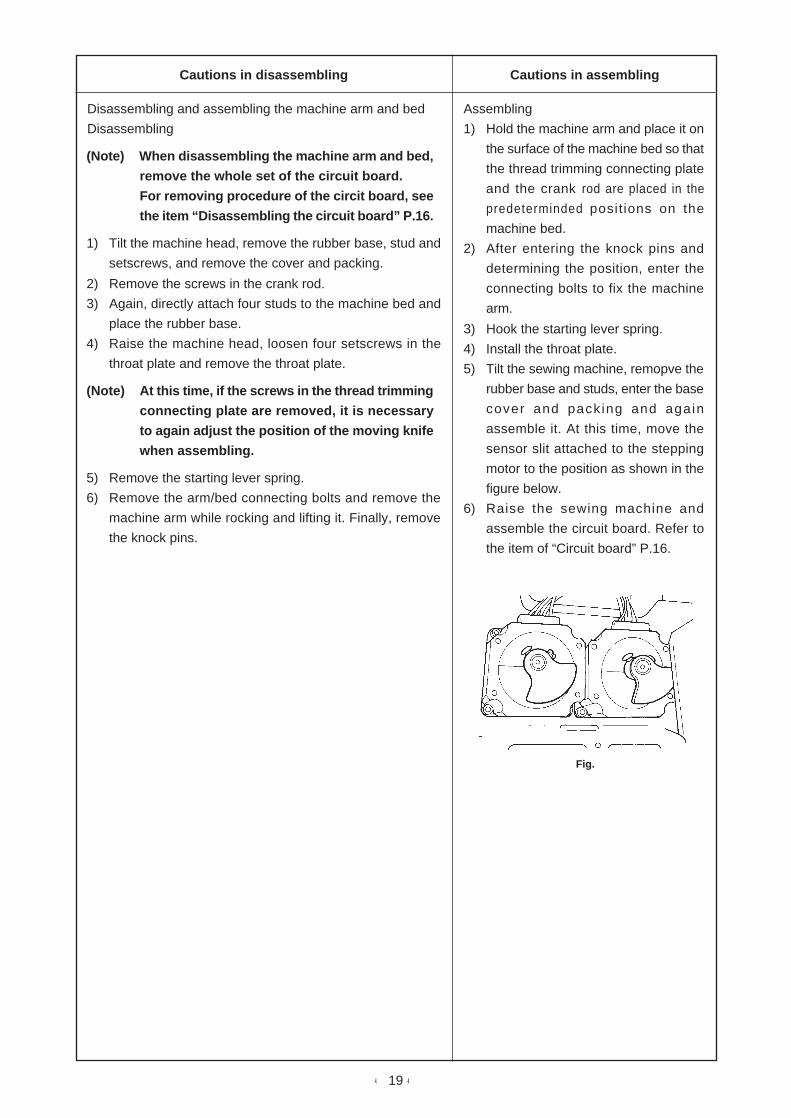
Disassembling and assembling the machine arm and bed
Disassembling
(Note) When disassembling the machine arm and bed,
remove the whole set of the circuit board.
For removing procedure of the circit board, see
the item “Disassembling the circuit board” P.16.
1) Tilt the machine head, remove the rubber base, stud and
setscrews, and remove the cover and packing.
2) Remove the screws in the crank rod.
3) Again, directly attach four studs to the machine bed and
place the rubber base.
4) Raise the machine head, loosen four setscrews in the
throat plate and remove the throat plate.
(Note) At this time, if the screws in the thread trimming
connecting plate are removed, it is necessary
to again adjust the position of the moving knife
when assembling.
5) Remove the starting lever spring.
6) Remove the arm/bed connecting bolts and remove the
machine arm while rocking and lifting it. Finally, remove
the knock pins.
Assembling
1) Hold the machine arm and place it on
the surface of the machine bed so that
the thread trimming connecting plate
and the crank rod are placed in the
predeterminded posit ions on the
machine bed.
2) After entering the knock pins and
determining the position, enter the
connecting bolts to fix the machine
arm.
3) Hook the starting lever spring.
4) Install the throat plate.
5) Tilt the sewing machine, remopve the
rubber base and studs, enter the base
cover and packing and again
assemble it. At this time, move the
sensor slit attached to the stepping
motor to the position as shown in the
figure below.
6) Raise the sewing machine and
assemble the circuit board. Refer to
the item of “Circuit board” P.16.
Fig.
Cautions in disassembling Cautions in assembling

- 20 -
(4) Disassembling the looper shaft
1) Disassembling
2) Screw gear components
3) Adjustment
Screw gear
Looper support screw
Oil seal
Loop positioning finger cam setscrew
Needle bearing
Thrust collar
Looper installing shaft
Triangle loop positioning finger cam
Looper shaft
Thrust collar
Thrust bearing
Needle bearing
Thrust bearing
Loop positioning finger cam
Thrust collar0.01 to 0.5 mm
43.5 mm
0.01 to 0.5 mm
A B
Procedures in disassembling and assembling

- 21 -
Disassembling and assembling the looper shaft
Disassembling
1) Disassemble the machine arm and bed. Refer to the item
“Disassembling the machine arm and bed” P.18.
2) Remove the throat plate and remove the components
related to the yoke slide and the looper.
(Same components as those of MB-373)
3) Loosen the setscrews of the screw gear and tilt the
machine bed.
4) Loosen the setscrews of the thrust collars and draw out
the looper shaft in the direction of the arrow mark (f).
Assembling
1) Fully apply grease to the inside of the
bushing.
(It is not necessary when filling grease
with grease gun or the like from the
grease hole on the surface of the
machine bed after setting up.)
2) Enter two thrust collars and the screw
gear on the looper shaft.
3) Fit the thrust collars at the position
where the dimension from section A
to top end B of looper shaft is 43.5
mm.
4) The thrust collar in the front side is for
prevention of slip-off of the needle
bering. Press the looper shaft
backward (in the direction of the arrow
a) and fix it so that a clearance of 0.1
to 0.5 mm is provided between the
thrust collar and the bushing.
5) Raise the sewing machine and tighten
the screw gear. At this time, adjust the
thrust play of the looper shaft to 0.01
to 0.5 mm.
6) Assemble the components related to
the looper and the yoke slide.
(Same adjustment as that of MB-373)
Cautions in disassembling Cautions in assembling

- 22 -
(5) Disassembling the driving shaft
• Disassembling
1) For the removing procedure of the circuit board, base cover and crank rod, see P.18.
2) Bushing and stator setscrew
4) Motor cover 5) Driving shaft (asm.) 6) Encoder
7) Stator 8) Rotor 9) Setscrew and bushing of screw gear
• Assembling
1) Screw gear 4) Rotor 5) Stator
8) Bushing
Motor cover
Ball bearing
Encoder
Driving shaft bushing, left
Ball bearing
Servo-motor
Stator setscrew
Bushing setscrew
Screw gearCrank rod
Thrust bearing
Driving shaft bushing, right
Ball bearing
4 to 4.2 mm 7.6 to 7.8 mm
Stator setscrew
Stator
Thrust bearing
Screw gearHand pulley
Bushing, rightBushing, left
7.7 mm
Procedures in disassembling and assembling

- 23 -
Disassembling and assembling of the driving shaft(Note) Do not disassemble the driving shaft except
when it has broken since since the motor isbuilt in.
Disassembling** Prepare before disassembling a clean board which is
not affected by magnetism and a piece of clean cloth sothat the rotor is not directly touched by hand.
1) Remove the circuit board. See the item “Circuit board”P.16.Tilt the sewing machine, remove the base cover andremove the setscrews in the crank rod.
2) Loosen setscrews in the bushing, setscrews in the statorand loosen the hand pulley.
3) Assemble again the studs and the rubber base, and raisethe sewing machine.
4) Remove setscrews in the motor cover and draw out thewhole driving shaft.
5) Put the driving shaft which has been drawn out on a cleanboard which is not affected by magnetism.
** Once again pay attention to the following matters beforedisassembling the driving shaft which has been drawnout.1 Chech whether there is anything such as iron powder
or the like which is attracted by the magnet in theneighbourhood.
2 Check whether there is any electronic apparatuswhich is easily affected by the magnetism.
3 Prepare a piece of clean cloth to wrap the rotor.4 Wash the hands to make them clean.
6) Loosen setscrews and draw out the encoder together withthe motor cover.
7) Draw out the stator from the driving shaft. Pressing thedriving shaft, slowly draw out the stator with force on theboard since the stator is pulled by the strong magnetismfrom the rotor located inside the stator.
(Note) If the force is quickly applied, the stator and therotor come off suddenly at the position wherethe magnetism is lost. As a result, the parts maybe dropped. So, be careful.
8) Hold the rotor so that it is wrapped in a piece of cleancloth, loosen the setscrew, and draw it out from the drivingshaft.Wrap the rotor which has been drawn out in a piece ofcloth.
(Note) The black section of the rotor is a strongmagnet.If there is a screwdriver or a screw in theneibourhood, it is attracted to the manet withforce. As a result, it may be broken by the shock.So, be careful.
9) Loosen the setscrew in the screw gear, and removebushings, right and left, thrust bearing and hand pulley.
Assembling
1) Install the screw gear.
(Clearance : 4 to 4.2 mm)
2) Enter the thrust bearing and the
bushings, and install the hand pulley.
3) Install the rotor. Hold it so that the
screw section comes out and install it
so that there is no clearance in the
thrust direction.
4) In this state, enter the rotor in the
machine bed.
Do not take the cloth covering the rotor.
5) Next, enter the stator. Set the direction
of the cord as shown in the figure and
slowly enter the stator while pressing
the driving shaft. When the magnetism
of the rotor works, the stator enters
with force as if it is absorbed. On the
contrary, the driving shaft tries to jump
out. Accordingly, hold the driving shaft
by hand.
6) Install the motor cover.
Keep the setscrew in the encoder held
loosened.
7) Tilt the sewing machine.
8) First, determine the position of the
bushing on the right-hand side.
Fix it so that the dimension from the
end face of the machine bed is 7.7 mm.
9) Next, fix the bushing on the left-hand
side while making the driving shaft
come in contact with the bushing on
the right-hand side.
10) Fix the crank rod.
11) Remove the studs and the rubber base
and again assemble them together
with the base cover and the packing.
At this time, move the sensor slit attached
to to the stepping motor.
For the position of the sensor slit, refer
to the figure on P.19.
Cautions in disassembling Cautions in assembling

- 24 -
(5) Disassembling the driving shaft
• Assembling and adjusting procedure of the servo-motor
15) Stator setscrew 16) Cord outlet 17) Operation panel
18) Panel display 20) Fixing stator 21) Encoder
23) Encoder setscrew 24) Encoder “0” display
Stator setscrew
Cord outlet
Encoderinstalling screw
Driving shaft setscrew
Procedures in disassembling and assembling

- 25 -
12) Raise the sewing machine and installthe circuit board. Refer to the item“Circuit board”. P.16.
13) Connect all connectors with the sidecover removedand install the controlbox cover.
14) Tilt the sewing machine. Turn the handpulley to bring the needle bar to itslowest position.
15) Check that the stator setscrew isloosened.
16) Enter the stator cord so that it comesto the cord outlet. At this time, do notfix the stator.
17) Pressing three buttons (arrow mark,“-”, and arrow mark from the top)located on the left end of the operationpanel, turn ON the power.
18) [no] is displayed in the display sectionof the operation panel.
19) In this state, the stator is in theexcitation mode, and the rotor and thestator are fixed.At this time, “W” phase and “V” phaseof the rotor are excited.Excitation duty is 20% and currentvalue is approximately 4 [A].
20) In this state, turn again the hand pulleyand adjust so that the needle bar isbrought to its lowest position. Fix thestator in this state. The rotor and thestator have come to the most properposition since they are pulling eachother.
21) Raise the sewing machine. Enter thehexagonal wrench key when theencoder setscrew is at the position asshown in the figure.(Encoder should be temporarilytightened in the center of the slot.)
22) Pressing the three buttons located onthe left side of the operation panel, turnON the power.
23) Loosen the driving shaft setscrews ofthe encoder and fix them at theposition where the setscrew No. 1comes almost just above.(The position just above overlaps withthe encoder screw. Tighten the screwat the slighly front side.) Hand tightening
24) Loosen the encoder setscrews, adjustthe position to “0” while observing theoperation panel. Then tighten thesetscrews.(The value varies –9 to +9.)20 to 40 kgf
25) Turn OFF the power and install theside cover.
26) Tighten the stator setscrew.
Cautions in disassembling Cautions in assembling

- 26 -
(1) Adjusting the starting sensor
7. ADJUSTMENT OF THE SENSORS
(2) Adjusting the presser lifter sensor
Needle
Presser lifter sensorplate setscrew
Presser lifterlowering sensor LD1
Presser lifterlifting sensor LD4
Moving knife
Setscrew
Presser lifter sensor
Thrust collarStarting lever
Sensor slit
Starting sensor
Sensor slit
Starting sensor plate setscrew
Starting lever
Starting leverbracket setscrew
Startingsensor
Starting lever stopper Starting leverbracket
1
Standard Adjustment

- 27 -
(1) Adjusting the starting sensor1) Loosen the starting sensor plate setscrews.
2) In the state that the starting lever comes in contact with
the starting lever stopper, adjust so that the sensor slit
does not pass the sensor and is as high as the sensor,
and fix the starting sensor plate setscrews. (20 to 30 kgf)
3) For the crosswise direction, loosen the starting lever
bracket setscrews and adjust so that the sensor slit of the
starting lever passes the center of the sensor.
4) When the aforementioned adjustment cannot complete
the adjustment, loosen the sensor slit setscrews and adjust
the position of the sensor slit.
(2) Adjusting the presser lifter sensor1) Remove the top cover and the control box cover.
2) Tilt the sewing machine.
(When the machine is put in this state, the sewing machine
does not rotate if the starting pedal is depressed by mistake
when adjusting with the power switch ON.)
3) Turn ON the power switch and press the presser lifter
switch, and loosen presser lifter sensor plate setscrews
1 with the presser lifted.
4) When the sewing machine is in the starting possible
position (position where moving knife does not come in
contact with needle), adjust so that LD1 on the MAIN circuit
board goes out, then lights up, and fix the sensor with the
setscrews.
5) Check that LD4 on the MAIN circuit board goes out, then
lights up when the presser is lifted by 2 to 3 mm from the
throat plate with the knot-tying adjusting plate.
Adjustment Procedures Results of Improper Adjustment

- 28 -
(3) Adjusting the feed origin sensor
Sensor slits are in the same direction.
(4) Adjusting the presser lifter stopper
Sensor slit
Setscrew
Origin sensor
Origin sensor installing plate setscrew
Origin sensorinstalling platesetscrew
Originsensor,left LD2
Originsensor,right LD3
10 mm
Standard Adjustment

- 29 -
(3) Adjusting the feed origin sensor1) Remove the hinge screw attached to the machine arm,
enter the sensors in the hole of the feed plate, and fix
them with the screw hole in the bed.
2) Tilt the sewing machine.
3) Turn ON the power switch. (Remove the control box cover.)
4) Loosen the origin sensor installing plate setscrews.
5) Fix the left-hand sensor as observed from the front of the
sewing machine at the position where LD2 on the MAIN
circuit board goes out, then lights up. (30 to 40 kgf)
6) Fix the right-hand sensor as observed from the front of
the sewing machine at the position where LD3 on the MAIN
circuit board goes out, then lights up. (30 to 40 kgf)
(4) Adjusting the presser lifter stopper1) Loosen the nut and adjust so that the distance from the
end face of the machine arm to the end face of the presser
lifter stopper should be 10 mm.
Adjustment Procedures Results of Improper Adjustment

- 30 -
8. HOW TO OPERATE AND USE THE MEMORY SWITCH (SERVICE LEVEL)
The operation to adapt the various specifications, more stabilized stitching, etc. can be performed by selecting
or changing the various operations, various timings, time, etc. of the sewing machine.
1) Pressing – /Backward switch and + /Forward switch, turn ON the power, and the display section becomes
as shown below. Then the mode will be the display model of the user level. At this time, all of the stitch
shape selection LED and the item selection LED flash on and off.
2) In this state, keep pressing – /Backward switch and + /Forward switch for 5 seconds. Then the display
section becomes as shown below, and the mode will be the display mode of the service level. At this time,
all of the stitch shape selection LED and the item selection LED flash on and off.
3) When the display mode of the service level appeared, press Set ready switch . Then the display section
becomes as shown below, and the memory switch No. 1 is displayed. The mode becomes the setting mode
of the service level.
At this time, all of the stitch shape selection LED flash on and off and only the pattern No. LED of the item
selection LED lights up.
4) Here, select the memory switch No. desired to be changed by pressing down – /Backward and + /Forward
switches. In this state, press Item selection switch and the display section becomes as shown below
(when the memory switch No. 1 is selected). Then set value corresponding to the memory switch No. is
displayed.
At this time, all of the stitch shape selection LED flash on and off, and the pattern No. LED of the item
selection LED goes out. In addition, when Item selection switch is pressed again, the state of step 3) will
appear.
5) In this state, set the value to the one desired to be changed by pressing down – /Backward and + /Forward
switches.
When the setting has been completed, turn OFF the power.
Display section(Flashing display)
Display section
(Flashing display)
Display section
(Light-up display)
[Memory switch No. 1][Soft-start speed setting]
Display section
(Light-up display)
[Set value of memory switch No. 1]

- 31
-
(1) Memory switch function table
Unit
x100 [rpm]
x100 [rpm]
x100 [rpm]
x100 [rpm]
x100 [rpm]
x100 [rpm]
0 : Ineffective1 : Effective
0 : Ineffective1 : Effective
x10 [deg]
[sec]
x10 [msec]
x10 [msec]
Setting range
4 to 18
4 to 18
4 to 18
4 to 18
4 to 18
4 to 18
0/1
0/1
0 to 40
0 to 10
0 to 20
2 to 20
Setting level
User
User
User
User
User
User
User
User
Service
Service
Service
Service
Settinginitial value
18
18
18
18
18
18
1
0
18
5
5
5
Memoryswitch No.
1
2
3
4
5
6
7
8
30
31
32
33
Soft start speed setting(1st stitch at the sewing start)
Soft start speed setting(2nd stitch at the sewing start)
Soft start speed setting(3rd stitch at the sewing start)
Soft start speed setting(1st stitch at the sewing start aftertrimming crossover thread)
Soft start speed setting(2nd stitch at the sewing start aftertrimming crossover thread)
Soft start speed setting(3rd stitch at the sewing start aftertrimming crossover thread)
Knot-tying function selection
Wiper function selection
Knot-tying solenoid ON timing angle setting(When memory switch No. 7, knot-tyingfunction is selected)
Knot-tying solenoid OFF timing time setting(When memory switch No. 7, knot-tyingfunction is selected)
Wiper solenoid ON timing time setting(When memory switch No. 8, wiperfunction is selected)
Wiper solenoid ON hold time setting(When memory switch No. 8, wiperfunction is selected)
Speed of 1st stitch at the sewing start can be limited.
Speed of 2nd stitch at the sewing start can be limited.
Speed of 3rd stitch at the sewing start can be limited.
Speed of 1st stitch at the sewing start after trimming crossover thread can belimited.
Speed of 2nd stitch at the sewing start after trimming crossover thread canbe limited.
Speed of 3rd stitch at the sewing start after trimming crossover thread can belimited.
Drawing out thread at the sewing end is stopped and thread can be knotted.
When the without-crossover thread device is mounted, needle thread after threadtrimming can be wiped. In case the without-crossover thread device is mounted andthe pattern without crossover thread is selected at setting “0” : ineffective, needle threadis automatically wiped only after trimming crossover thread (medium thread trimming).
Knot-tying solenoid ON timing angle (upper dead point of one stitch beforethe last stitch is regarded as 0˚) can be changed.
Period of time of Knot-tying solenoid OFF timing can be changed.
Period of time from thread trimming to wiper solenoid ON timing can be changed.
Period of holding time from wiper solenoid ON can be changed.As the number is increased, the operating time of wiper becomes longer.
Setting item Contents of setting

- 32
-
Unit
x10 [deg]
x10 [msec]
–
[msec]
–
x10 [msec]
Pulse
Pulse
x10 [msec]
–
[deg]
0 : Hole position1 : Medium position
Setting range
0 to 40
0 to 20
0 to 10
30 to 90
0 to 10
10 to 40
-9 to 9
-9 to 9
5 to 20
0 to 10
-9 to 9
0/1
Setting level
Service
Service
Service
Service
Service
Service
Service
Service
Service
Service
Service
Service
Settinginitial value
20
0
6
45
6
24
0
0
10
6
0
1
Memoryswitch No.
34
35
36
37
38
39
40
41
44
45
46
47
Thread trimming operation setting (1)
Thread trimming (presser lifting) solenoid ON timingtime setting
Presser lifting holding force setting
Thread trimming operation setting (2)[Crossover thread trimming when without crossover threadpattern is selected (medium thread trimming), or threadtrimming when memory switch No. 8, wiper function is selected.]
Thread trimming operation setting (3)[Crossover thread trimming when without crossover threadpattern is selected (medium thread trimming), or threadtrimming when memory switch No. 8, wiper function is selected.]
Thread trimming operation setting (4)[Crossover thread trimming when without crossover threadpattern is selected (medium thread trimming), or threadtrimming when memory switch No. 8, wiper function is selected.]
Thread trimming position setting (1)
Thread trimming position setting (2)
Thread trimming operation setting (1) [For BR]
Thread trimming operation setting (2) [For BR]
Feed pulse delivery timing setting
Thread trimming position function selection
Thread trimming (presser lifting) solenoid ON timing angle (upperdead point of one stitch before the last stitch is regarded as 0˚)can be changed. As the number is increased, the thread trimmingtiming is delayed. As the number is decreased, thread trimmermay interfere with needle. So, be careful.
Do not change.
Holding force when the presser goes up can be changed.As the number is increased, the holding force is strengthened.
Thread trimming operation can be adjusted.As the number is increased, operating force of thread trimmingis strengthened. However, the presser foot may rise. So, becareful.
Do not change.
Do not change.
Thread trimming position can be adjusted. Thread trimming position isdetermined by the set value of memory switch No. 40, thread trimmingposition setting (1) or No. 41, thread trimming position setting (2).
Thread trimming position can be adjusted. Thread trimming position isdetermined by the set value of memory switch No. 40, thread trimmingposition setting (1) or No. 41, thread trimming position setting (2).
Thread trimming operation can be adjusted. As the number is
increased, operating force of thread trimming is strengthened.
Do not change.
Do not change.
Thread trimming position can be selected.
Setting item Contents of setting

- 33 -
9. HOW TO OPERATE AND USE THE INPUT CHECK MODE FUNCTION
Troubles, defects, etc. of the printed circuit boards and elements can be checked by displaying the input state
of the various sensors and switches.
1) Pressing Set ready switch and Reset switch, turn ON the power. (“Function No. 1” is displayed.)
2) When Item selection switch is pressed down, the state of input assigned to “Function No. 1” is displayed.
3) In this state, when the feed mechanism, detecting plate, etc. are moved, the display changes in accordance
with the input state of the origin sensor. In this case, when the display is “1”, the origin sensor is in the input
state of OFF and when the display is “0”, the origin sensor is in the input state of ON.
4) When performing checking of other function No, press down Item selection switch again and the display
becomes the display state of step 1). In this state, select the function No. you desire to check by ptressing
down – /Backward and + /Forward switches and perform the operation of step 2).
Display section
(Flashing display)
Display section
(Light-up display)
[Example of display]
(Caution) Input of the origin sensor of feed stepping motor is assigned to “Function No. 1”. In this case,
left-hand side (10th digit) of the display section, as observed from the front of the sewing
machine, is the input state of the origin sensor of left-hand side stepping motor, and right-
hand side (1st digit) of the display section, as observed from the front of the sewing machine,
is the input state of the origin sensor of right-hand side stepping motor.

- 34 -
(1) INPUT CHECK CORRESPONDENCE TABLE
FunctionNo.
Left-hand side of display section(10th digit)
Origin detection sensor (Left stepping motor)
: ON, : OFF [CN20-2]
Presser lifting detection sensor
: ON, : OFF [CN30-2]
Pedal start SW
: ON, : OFF [CN22-2]
STMG (Input signal for BR)
: ON, : OFF [CN24-2]
Pedal start SW
: ON, : OFF [CN28-2]
Not used.
[CN27-2]
Operation panel : Reset SW
: ON, : OFF [CN25-17]
Operation panel : - /Backward SW
: ON, : OFF [CN25-19]
Operation panel : Set ready SW
: ON, : OFF [CN25-22]
Not used.
[CN25-24]
SW1-1 (DIP SW)
: ON, : OFF
SW1-3 (DIP SW)
: ON, : OFF
SW1-5 (DIP SW)
: ON, : OFF
SW1-7 (DIP SW)
: ON, : OFF
Right-hand side of display section(1st digit)
Origin detection sensor (Right stepping motor)
: ON, : OFF [CN21-2]
Presser lowering detection sensor
: ON, : OFF [CN30-5]
Not used.
[CN23-2]
WMG (Input signal for BR)
: ON, : OFF [CN24-4]
Pedal presser SW
: ON, : OFF [CN28-5]
Not used.
[CN27-5]
Operation panel : Stitch shape selection SW
: ON, : OFF [CN25-18]
Operation panel : + /Forward SW
: ON, : OFF [CN25-20]
Operation panel : Presser SW
: ON, : OFF [CN25-23]
Overheat monitoring sensor
: ON, : OFF [CN29-1]
SW1-2 (DIP SW)
: ON, : OFF
SW1-4 (DIP SW)
: ON, : OFF
SW1-6 (DIP SW)
: ON, : OFF
SW1-8 (DIP SW)
: ON, : OFF

- 35 -
10. HOW TO OPERATE AND USE THE ALL CLEAR FUNCTION
All of the data (size, number of stitches, etc.) of each pattern No. and the set value of the memory switch can be
cleared and returned to the set value at the time of delivery. However, when this operation is performed, all the
up-to-date data are deleted. So, be careful
1) Pressing Presser lifting switch and Reset switch, turn ON the power and the display section becomes as
shown below.
2) In this state, press Reset switch and the display section becomes as shown below. Then data deletion
operation starts.
3) When the data deletion operation has been completed, the display section becomes as shown below, and
the flashing is changed to light-up state. At this time, turn ON the power again after turning OFF the power,
and the set value is returned to the one at the time of delivery.
Display section(Flashing display)
Display section
(Light-up display)
Display section
(Light-up display)

- 36 -
11. PARTS TO BE GREASESDApply or fill up grease to the following parts.
Cra
nk ro
d hi
nge
scre
w
Roc
king
rod
fulc
rum
sha
ft
Nee
dle
bar
uppe
r bu
shin
g
Nee
dle
bar
clam
p
Nee
dle
bar
low
er b
ushi
ng
Yok
e sl
ide
Tria
ngle
cam
Loop
pos
ition
ing
finge
r ca
m
Nee
dle
bear
ing
Thr
ust b
earin
g
Scr
ew g
ear
Cra
nk r
odF
eed
need
le b
earin
g
- 37 -
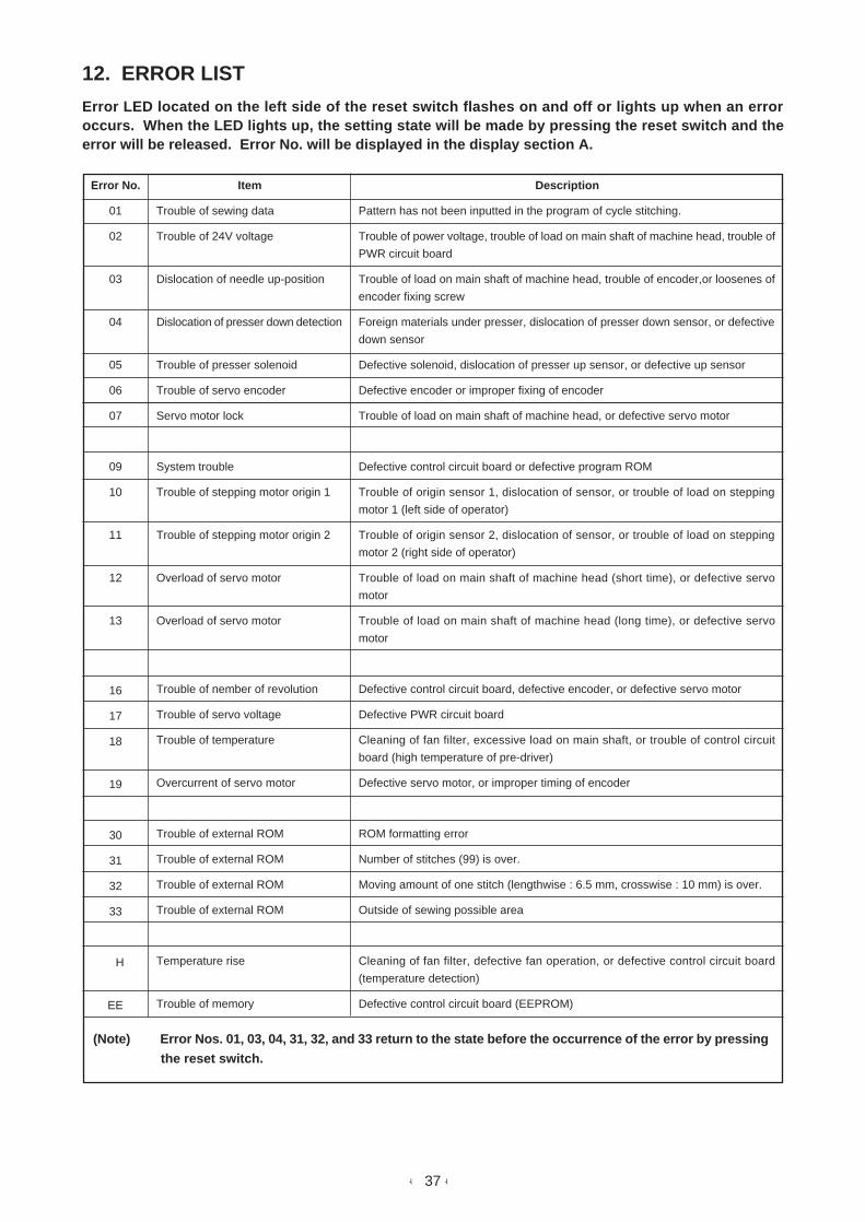
12. ERROR LIST
Error No.
01
02
03
04
05
06
07
09
10
11
12
13
16
17
18
19
30
31
32
33
H
EE
Item
Trouble of sewing data
Trouble of 24V voltage
Dislocation of needle up-position
Dislocation of presser down detection
Trouble of presser solenoid
Trouble of servo encoder
Servo motor lock
System trouble
Trouble of stepping motor origin 1
Trouble of stepping motor origin 2
Overload of servo motor
Overload of servo motor
Trouble of nember of revolution
Trouble of servo voltage
Trouble of temperature
Overcurrent of servo motor
Trouble of external ROM
Trouble of external ROM
Trouble of external ROM
Trouble of external ROM
Temperature rise
Trouble of memory
Description
Pattern has not been inputted in the program of cycle stitching.
Trouble of power voltage, trouble of load on main shaft of machine head, trouble of
PWR circuit board
Trouble of load on main shaft of machine head, trouble of encoder,or loosenes of
encoder fixing screw
Foreign materials under presser, dislocation of presser down sensor, or defective
down sensor
Defective solenoid, dislocation of presser up sensor, or defective up sensor
Defective encoder or improper fixing of encoder
Trouble of load on main shaft of machine head, or defective servo motor
Defective control circuit board or defective program ROM
Trouble of origin sensor 1, dislocation of sensor, or trouble of load on stepping
motor 1 (left side of operator)
Trouble of origin sensor 2, dislocation of sensor, or trouble of load on stepping
motor 2 (right side of operator)
Trouble of load on main shaft of machine head (short time), or defective servo
motor
Trouble of load on main shaft of machine head (long time), or defective servo
motor
Defective control circuit board, defective encoder, or defective servo motor
Defective PWR circuit board
Cleaning of fan filter, excessive load on main shaft, or trouble of control circuit
board (high temperature of pre-driver)
Defective servo motor, or improper timing of encoder
ROM formatting error
Number of stitches (99) is over.
Moving amount of one stitch (lengthwise : 6.5 mm, crosswise : 10 mm) is over.
Outside of sewing possible area
Cleaning of fan filter, defective fan operation, or defective control circuit board
(temperature detection)
Defective control circuit board (EEPROM)
Error LED located on the left side of the reset switch flashes on and off or lights up when an erroroccurs. When the LED lights up, the setting state will be made by pressing the reset switch and theerror will be released. Error No. will be displayed in the display section A.
(Note) Error Nos. 01, 03, 04, 31, 32, and 33 return to the state before the occurrence of the error by pressing
the reset switch.

- 38 -
13. CHANGE-OVER OF THE POWER SOURCE VOLTAGE
This sewing machine has been connected to the power source of 200V to 240V in the state of delivery from the
factory.
When using the machine with the power source of 100V to 120V, perform the work of change-over of voltage in
the order of the procedures below.
1) Remove the cover in the rear of the sewing machine and replace from 200V to 100V the connector of
connector No. CN32 (blue 2-pin) on the right side PWR circuit board as observed from the front side.
See the figure below.
2) Install the cover.
3) Connect the power plug to the receptacle.
4) Completion of the work.
(Caution)1. Perform the change-over after confirming the voltage of the place where the sewing machine
is set and the voltage in the sewing machine.
2. Do not connect the power plug to the receptacle.
CN32 connector section

- 39 -
14. CAUSE OF TROUBLES AND THE CORRECTIVE MEASURES(1) Thread trimming troubles and the corrective measures
Troubles Causes Corrective measures
Correct the position of the moving knife
at the time of completion of the stop
motion.
Refer to the item “5. (2) Adjusting the
position of the moving knife”.
2. Both the thread on the
needle and that on the
wrong side of a fabric are
trimmed.
The trimming timing of the moving
knife is bad.
1. Thread is not trimmed. The thread separating claw of the
moving knife fails to separate the
thread on a fabric from that on the
needle.
Adjust the position of the moving knife.
Refer to the item “5. (2) Adjusting the
position of the moving knife”.
The needle does not come down
into the correct point of a button
hole.
Make readjustment by the button
clamp holder.
The final stitch is skipped. Correct the position on the looper.
Refer to the item “4. (2) Positioning the
needle and the looper”.
The height of the thread separating
claw of the moving knife is not
correct.
Correct the height of the thread
separating claw of the moving knife.
Refer to the item “5. (3) Adjusting the
height of the thread separating claw
of the moving knife”.
Improper position of the moving
knife
3. The trimmed thread on the
wrong side of a fabric is too
long.
Improper height of the thread
separating claw of the moving
knife.
Correct the height of the thread
separating claw of the moving knife.
Refer to the item “5. (3) Adjusting the
height of the thread separating claw
of the moving knife”.
The lift of the button clamp is too
large.
Correct the position of the moving
knife.
Refer to the item “5. (2) Adjusting the
position of the moving knife”.
Readjust the lift to 10 mm.
Refer to the item “4. (5) Lift and
pressure of the button clamp”.
(Caution) Adjust the position of the moving knife within a range of 10 to 15 mm.
If the position of the moving knife is readjusted to less than 10 mm, the thread separating claw comes in
contact with the counter knife or the yoke slide insert, resulting in damaged thread separating claw of
the moving knife.
On the other hand, if it is readjusted to more than 15 mm, the thread separating claw may come in
contact with the positioning finger yoke slide while the machine is running, also causing breakage of
the thread separating claw.

- 40 -
Troubles Causes Corrective measures
(2) Cause of troubles and the corrective measures for MB-1800
1. The machine fails to sew atthe start of sewing.
Length of remaining thread is tooshort.
Adjust the thread adjusting threadguide.
Speed is fast. Use the soft-start function.
The needle is too thick for thediameter of the hole in the button.
Replace the needle with a thinner one.
The thread tension post No. 2 failsto release the thread at correcttiming.
Make the thread releasing timingslightly earlier.
The needle does not enter thecenter of the holes in the button.
Adjust the position of the button clampjaw lever holder.
2. Thread breakage
The needle does not enter thecenter of the holes in the button.
Adjust athe position of the buttonclamp jaw lever holder.
The thread tension post No. 2 failsto release the thread at correcttiming.
Make the thread releasing timingslightly earlier.
The thread tension post No. 2 doesnot give sufficient tension.
Increase the tension of the threadtension post No. 2.
3. Buttons are not sewn tightly.
The last stitch skips. Adjust the looper.
The moving knife does not separatethe thread on the fabric with itsthread separating claw.
Adjust the position of the moving knife.
The needle does not enter thecenter of the holes in the button.
Adjust the position of the button clampjaw lever holder.
4. Thread cannot be trimmed.
The moving knife does not separatethe thread on the fabric with itsthread separating claw.
Adjust the height of the threadseparating claw.
The moving knife does not separatethe thread on the fabric with itsthread separating claw.
Adjust the position of the moving knife.
The moving knife separation nail istoo high or too low.
Adjust the height of the threadseparating claw.
5. Needle thread is cut in twoplaces.
- 41 -
15. CIRCUIT BOARD DIAGRAM(1) MAIN circuit board

- 42 -
(2) PWR circuit board
(3) PANEL circuit board

- 43 -
16. BLOCK DIAGRAM 1/2
PA
NE
L pc
b as
m.
CN
41
26P
3
Fee
d 1
step
ping
mot
or
!2
!3
Fee
d 2
step
ping
mot
or
!4
Ser
vo-m
otor
!5 S
ervo
-enc
oder
2P
WR
pcb
asm
.
8!7
!6
6P
CN
17
15P
CN
19
4P 7P
CN
18
CN
24
6P
CN
26
6P
CN
16
26P
CN
25
Inte
rfac
e fo
r B
R
Ser
ial i
nter
face
6P
CN
11
2P
CN
29
6P
CN
33
2P
CN
35
Contr
ol bo
x pow
er co
rd as
m.
6P
CN
26P
ower
sw
itch
Pow
er c
ord
asm
.
2PC
N32
7In
put c
hang
e-ov
er c
ord
asm
.(C
hang
e-ov
er 1
00V
/200
V)
5T
empe
ratu
re
sens
or c
ord
asm
.
1
MA
IN p
cb A
asm
.
!1P
ress
er s
enso
r co
rd a
sm.
!0 Sta
rtin
g co
rd a
sm.
CN
27
6P
CN
28
9P
CN
23
3P
CN
22
3P
CN
15
2P
CN
14
2P
CN
12
2P
CN
13
2P
CN
20
3P
CN
21
3P
CN
30
6P
6 Thre
ad te
nsio
n re
lay
cord
asm
.
CN
58
2P2P
3P 3P 3P3P 3P
CN
51
CN
52
CN
53
CN
54
CN
55
9F
eed
orig
in c
ord
asm
.
@8P
edal
sw
itch
asm
.
@9P
edal
cor
d as
m.
3P
CN
56
3P
CN
57
Pre
sser
lift
er
sole
noid
asm
.
Kn
ot-
tyin
g
sole
noid
asm
.
Wip
er s
olen
oid
asm
.
Thre
ad te
nsio
n
sole
noid
asm
.
Fee
d 1
orig
in
sens
or
Fee
d 2
orig
in
sens
or
Star
ting
switc
h
Pre
sser
lifti
ng
sens
or
Pre
sser
low
erin
g se
nsor
Fan
asm
.
Pre
sser
sw
itch
Sta
rt s
witc
h
!8
!9
@0
@1
@2
@3
@4
@5
@6
@7
#0
#1

- 44 -
Block diagram 2/2
Sensor connection diagram
Solenoid circuit diagram
Power connection diagram
Power connection diagram
Sensor connection diagram
Sensor connection diagram
Sensor connection diagram
Motor circuit diagram
Motor circuit diagram
Motor circuit diagram
Encoder circuit diagram
Power connection diagram
Power connection diagram
Solenoid circuit diagram
Solenoid circuit diagram
Solenoid circuit diagram
Solenoid circuit diagram
Sensor connection diagram
Sensor connection diagram
Sensor connection diagram
Sensor connection diagram
Sensor connection diagram
Power connection diagram
Sensor connection diagram
Sensor connection diagram
Sensor connection diagram
Sensor connection diagram
MAIN circuit board A asm.
PWR circuit board asm.
PANEL circuit board asm.
Temperature sensor cord asm.
Thread tension relay cord asm.
Input change-over cord asm.
Control box power cord asm.
Feed origin cord asm.
Starting cord asm.
Presser sensor cord asm.
Feed 1 stepping motor
Feed 2 stepping motor
Servo-motor
Servo-encoder
Power switch
Power cord asm.
Presser lifter solenoid asm.
Knot-tying solenoid asm.
Wiper solenoid asm.
Thread tension solenoid asm.
Feed 1 origin sensor
Feed 2 origin sensor
Starting switch
Presser lifting sensor
Presser lowering sensor
Fan asm.
Pedal switch asm.
Pedal cord asm.
Presser switch
Start switch
1
2
3
4
5
6
7
8
9
10
11
12
13
14
15
16
17
18
19
20
21
22
23
24
25
26
27
28
29
30
31
32
33
34
35
36
37
38
39
40
M8601630AA0
M86046300A0
M86026300A0
M85026300A0
M85196300A0
M85236000A0
M85046300A0
M85056300A0
M85066300A0
M85076300A0
M8901630000
M8901630000
M8903630000
M8904630000
HA004250000
M90245800A0
M85086300A0
M85096300B0
M85176300A0
M85186300A0
HD00057000A
HD00057000A
HD00057000A
HD000570000
HD000570000
M85405900A0
M85205900A0
M90115900A0A
HD001930000
HD001930000
No. Part No. Name of part Circuit diagram

- 45 -
17. CONNECTION DIAGRAM AND CIRCUIT DIAGRAM
(1) Power connection diagram
PE
1 1
2 2C
N31
V W FGU
Pow
er c
ord
asm
.
Gre
en
Red
Whi
te
Bla
ck
Pow
er S
W
L1T
1
L2T
2
L3T
3Li
ght b
lue
Bro
wn
Gre
en/Y
ello
w
Con
trol
box
pow
er c
ord
asm
.
FG
1F
G2A
CIN
AC
IN
1 1
2 2
1 1
2 2
Whi
te
Whi
te
CN
32 (
100V
)
100V
RT
N
CN
32 (
200V
)
NC
NC
PW
R p
cb a
sm.
MA
IN p
cb A
asm
.
1 1
2 2
3 3
FA
N a
sm.
N.C
1 2 3 4 5 6
N.C
N.C
N.C
N.C
N.C
CN
34 +15V
1
+15V
1R
ET
+15V
2
+15V
2R
ET
+15V
3
+15V
3R
ET
1 1
2 2
3 3
4 4
5 5
6 6
1 1
2 2
3 3
4 4
5 5
6 6
+24V
+24V
+5V
PG
ND
PG
ND
GN
D
CN
11C
N33
+24V
+24V +5
V
PG
ND
PG
ND
GN
D
DC
pow
er c
ord
asm
.
Ora
nge
Ora
nge
Red
Whi
te
Whi
te
Whi
te
CN
23
+24V
GN
DN
.CB
lack
Red
- 46 -
(2) Sensor connection diagram
OP
TIO
NA
L
1 2 3 4 5 6 7 8 9
+5V
PR
ES
SE
R
GN
D
+5V
ST
AR
T
GN
D
+5V
N.C
GN
D
CN
28
BLU
E
BR
OW
N
BLA
CK
BLU
E
BR
OW
N
BLA
CK
1 2 3 4 5 6
+5V
FE
ED
1 O
RIG
IN
GN
D
1 2 3
CN
20
BLU
E
BR
OW
N
BLA
CK
+5V
FE
ED
2 O
RIG
IN
GN
D
1 2 3
CN
21
+5V
ST
AR
TIN
G
GN
D
1 2 3
CN
22
+5V
PR
ES
SE
R L
IFT
GN
D
CN
30
+5V
PR
ES
SE
R L
OW
ER
GN
D
BLU
E
BR
OW
N
BLA
CK
BLU
E
BR
OW
N
BLA
CK
1 2
CN
29
TE
MP
. DE
TE
CT
GN
D
WH
ITE
BLA
CK
RE
D
WH
ITE
BLA
CK
GR
EE
NY
ELL
OW
BR
OW
N
3 2 1
CN
52
3 2 1
CN
52
3 2 1
CN
53
3 2 1
CN
53
3 2 1
CN
54
3 2 1
CN
54
3 2 1
CN
55
3 2 1
CN
55
3 2 1
CN
56
3 2 1
CN
56
3 2 1
CN
57
3 2 1
CN
57
3 2 1
CN
51
3 2 1
CN
51
BLU
E
BR
OW
N
BLA
CK
BLU
E
BR
OW
N
BLA
CK
BLU
E
BR
OW
N
BLA
CK
BLU
E
BR
OW
N
BLA
CK
BLU
E
BR
OW
N
BLA
CK
BLA
CK
RE
D
WH
ITE
BR
OW
N
GR
EE
N
YE
LLO
W
1 2
1 2
CN
35C
N35
WH
ITE
BLA
CK
PW
R P
CB
FE
ED
1 O
RIG
IN S
EN
SO
R
FE
ED
2 O
RIG
IN S
EN
SO
R
ST
AR
TIN
G S
W
PR
ES
SE
R
LIF
TIN
G S
EN
SO
R
PR
ES
SE
R
LOW
ER
ING
SE
NS
OR
PR
ES
SE
R S
W
ST
AR
T S
W
TE
MP
ER
AT
UR
E S
EN
SO
R85
˚

- 47 -
(3) Motor circuit diagram
V
W
U
A
A
B
A
A
B
B B
L1-A
+24V
L1-A
L1-B
+24V
L1-B
1
5
3
2
6
4
CN16
YELLOW
ORANGE
BLUE
RED
WHITE
BLACK
L2-A
+24V
L2-A
L2-B
+24V
L2-B
1
5
3
2
6
4YELLOW
ORANGE
BLUE
RED
WHITE
BLACK
CN17
FEED 1 STEPPING
MOTOR
FEED 2 STEPPING
MOTOR
SERVO-MOTOR
U
W
V
PGND
1
3
2
4
CN18RED
WHITE
BLACK
N.C
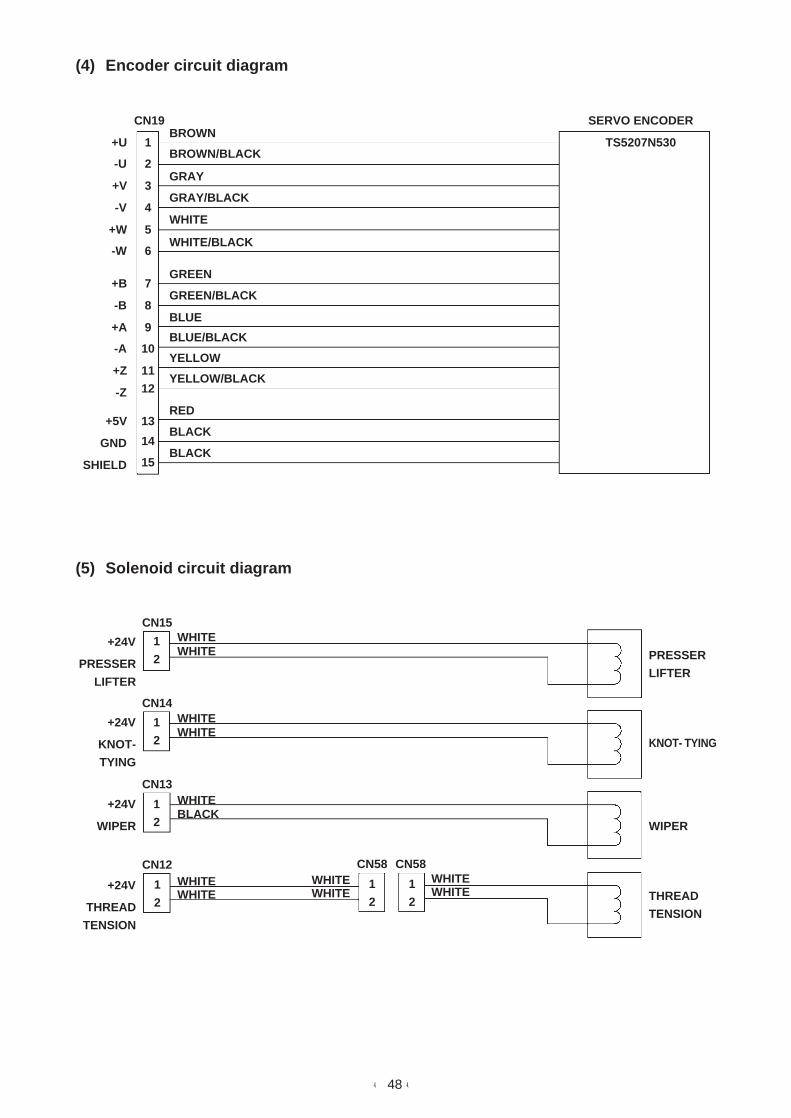
- 48 -
(4) Encoder circuit diagram
(5) Solenoid circuit diagram
+U
-U
+V
-V
+W
-W
+B
-B
+A
-A
+Z
-Z
+5V
GND
SHIELD
1
2
3
4
5
6
7
8
9
10
11
12
13
14
15BLACK
BROWN
BROWN/BLACK
GRAY
WHITE
WHITE/BLACK
GRAY/BLACK
GREEN
GREEN/BLACK
BLUE
BLUE/BLACK
YELLOW
YELLOW/BLACK
RED
BLACK
CN19 SERVO ENCODER
TS5207N530
+24V
PRESSER
LIFTER
+24V
KNOT-
TYING
+24V
WIPER
+24V
THREAD
TENSION
1
2
1
2
1
2
1
2
WHITEWHITE
WHITEWHITE
WHITEWHITE
WHITEBLACK
CN15
CN14
CN13
CN12
WHITEWHITE
WHITEWHITE1
2
1
2
CN58 CN58
THREAD
TENSION
PRESSER
LIFTER
KNOT- TYING
WIPER

- 49 -
18. DRAWING OF THE TABLE
R4
R4
(6)
R4 R4
R4
R4
R30
570
500
R30
R30
R30
120
525
980 81
0
220
390
360
105
115
35
190
112
2126
1050
160
2150
25
15
110
4663
160
78.5
2 dr
illed
hol
e, d
epth
10
(bot
tom
sur
face
)
Inst
allin
g po
sitio
n of
sto
pper
for
draw
er
30 d
rille
d ho
le
3-8
drill
ed h
ole
JUK
I log
otyp
e2
drill
ed h
ole,
dep
th 1
0 (b
otto
m s
urfa
ce)
Inst
allin
g po
sitio
n of
dra
wer
2-2
drill
ed h
ole,
dep
th 1
0 (b
otto
m s
urfa
ce)
Mai
n sw
itch
inst
allin
g po
sitio
n
40 d
rille
d ho
le
4-2
drill
ed h
ole,
dep
th 1
0 (b
otto
m s
urfa
ce)
Sta
nd in
stal
ling
hole
17 d
rille
d ho
le
R4
R4 40
3. Painting inside of cut portion is not necessary.
2. Do not peel the protection sheet from the surface of table.
(Note) 1. Tolerance of hole without indication is ± 0.7 and that of others ± 1.0.

Please do not hesitate to contact our distributors or agents in your area for further information when necessary.* The description covered in this engineer’s manual is subject to change for improvement of the
commodity without notice.
00 · 04 Printed in Japan (E)
R
INTERNATIONAL SALES DIVISION8-2-1. KOKURYO-CHO.CHOFU-SHI. TOKYO 182-8655. JAPANPHONE : (81)3-3430-4001 to 4005FAX : (81)3-3430-4909 • 4914 • 4984TELEX : J22967
Copyright C 2000 JUKI CORPORATION.
All rights reserved throughout the world.


![����-��Q�kTitle ����-��Q�k Author ï¿½ï¿½ï¿½Ý t�]�c Created Date �����-�](https://img.pdfslide.net/doc/110x75/60a3a35fc4ece70e851f9842/-qk-title-qk.jpg)


![nÃÛÖ] äËm†˙ å‚nÏ - Khalifatullah Mehdikhalifatullahmehdi.info/books/urdu/Majmua-Rasayel-BandagiMiyan-RZ.pdfï ï ï ï ï ï ï ï ï ï ï ï ï ï ï ï ï ï ï ï](https://img.pdfslide.net/doc/110x75/5e752ae12f0d2b679431cf1d/nf-ma-an-khalifatullah-meh-.jpg)