Embed Size (px)
Citation preview
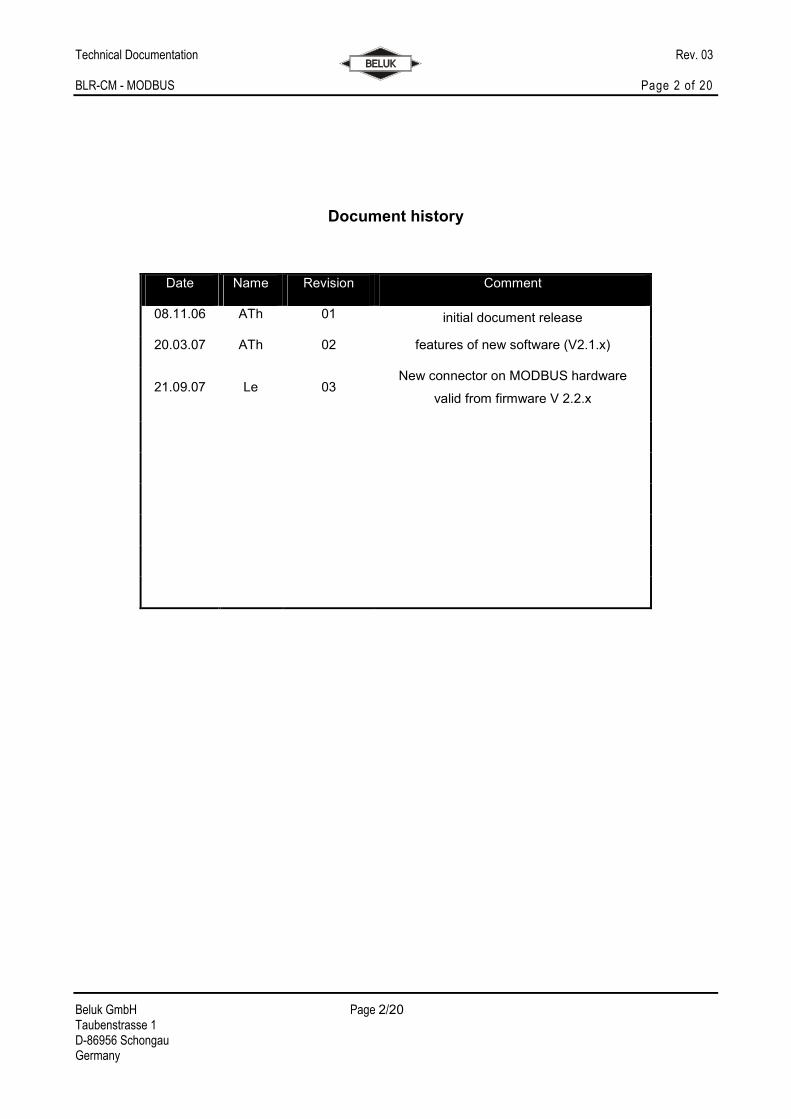
Technical Documentation Rev. 03 BLR-CM - MODBUS
Beluk GmbH Taubenstrasse 1 D-86956 Schongau Germany Tel.: +49/(0)8861/2332-0 Fax: +49/(0)8861/2332-22 e-mail: [email protected] http://www.beluk.de
Technical Documentation
BLR-CM MODBUS
Technical Documentation Rev. 03 BLR-CM - MODBUS Page 2 of 20
Beluk GmbH Page 2/20 Taubenstrasse 1 D-86956 Schongau Germany
Document history
Date Name Revision Comment
08.11.06 ATh 01 initial document release
20.03.07 ATh 02 features of new software (V2.1.x)
21.09.07 Le 03 New connector on MODBUS hardware
valid from firmware V 2.2.x
Technical Documentation Rev. 03 BLR-CM - MODBUS Page 3 of 20
Beluk GmbH Page 3/20 Taubenstrasse 1 D-86956 Schongau Germany
Content
1 OVERVIEW ................................................................................................................................................ 4
2 MODBUS / RS485...................................................................................................................................... 5
2.1 The physical layer - RS485 (defined in EIA485/ISO8482) ........................................................................ 5
2.1.1 Connection .................................................................................................................................................... 6
2.1.2 Line termination ............................................................................................................................................ 6
2.1.3 Line biasing ................................................................................................................................................... 7
2.1.4 Communication indicator............................................................................................................................. 7
2.2 The MODBUS protocol ..................................................................................................................................... 8
2.2.1 MODBUS - description ................................................................................................................................ 8
2.2.2 Serial data format and framing ................................................................................................................... 8
2.2.3 Serial transmission modes.......................................................................................................................... 9
2.2.4 Function codes ........................................................................................................................................... 10
2.2.5 Exception codes ......................................................................................................................................... 10
2.2.6 Master-Slave protocol................................................................................................................................ 10
2.2.7 BLR-CM - MODBUS setup ....................................................................................................................... 11
2.2.8 Address space ............................................................................................................................................ 11
2.2.9 Measurement values ................................................................................................................................. 12
2.2.10 Work counters............................................................................................................................................. 13
2.2.11 Parameter settings ..................................................................................................................................... 14
2.2.12 Step status .................................................................................................................................................. 15
2.2.13 Device status .............................................................................................................................................. 17
2.2.14 Storage settings.......................................................................................................................................... 19
3 TROUBLE SHOOTING............................................................................................................................ 20
Technical Documentation Rev. 03 BLR-CM - MODBUS Page 4 of 20
Beluk GmbH Page 4/20 Taubenstrasse 1 D-86956 Schongau Germany
Important information!
If the above sign appears besides a text passage in the manual the reader is strongly
advised to read the corresponding information, as it may be very important for usage of
the device.
It can contain safety advice or other information for the correct handling of the device.
If the information is disregarded, the device may be inoperable or even damaged!
Additional documentation for the MODBUS protocol can be found at www.modbus.org.
The MODBUS standards are also available from there.
1 Overview
The MODBUS Extension of the BLR-CM offers the possibility to read values from the device and modify the
settings of the device.
This document describes the transmission by use of the MODBUS-protocol. This protocol defines methods
for data transmission and access control, but doesn't restrict the user to one single physical transmission
system. In case of the BLR-CM, RS485 is used on the physical layer. As this is a bus-capable interface, it is
possible to connect more than one BLR-CM to a single pair of wires and access the units by use of an ID
number.
A lot of commercial devices and PLCs are able to use the MODBUS protocol, either as bus master or slave.
Various SCADA solutions are also available from different vendors. So, the integration of the BLR-CM in an
existing bus-system or setting up a new bus system is only a minor issue.
!
Technical Documentation Rev. 03 BLR-CM - MODBUS Page 5 of 20
Beluk GmbH Page 5/20 Taubenstrasse 1 D-86956 Schongau Germany
2 MODBUS / RS485
The implementation basically consists of two parts:
• The RS485 transmission is used for serial data transport. It is able to interconnect more than one
device in a bus-like configuration. The RS485 protocol offers its “services” to the higher-level
MODBUS protocol.
• The MODBUS protocol uses the underlying serial data transport layer (RS485 in this case) to
communicate with several bus devices. It defines commands, address structures and data structures
to access the slave device.
2.1 The physical layer - RS485 (defined in EIA485/ISO8482)
RS485 offers basic serial data transport to the higher-level MODBUS protocol layers. It is therefore called the
“physical layer” of the bus system. Higher layers use the lower physical layer as a basic “service“ for data
transport.
RS485 uses two data wires for serial transmission. Each of them is driven to 0V or 5V by the transmitting
device. The two data wires always have different voltage levels. One state (one wire 5V, other wire GND)
represents the logic “OFF” state. The two wires exchange their voltages for the logic “ON” state. This
differential transmission mode makes the RS485 bus very resistant against electro-magnetic distortions and
therefore allows long transmission distances of more than 1000 metres.
The data transmission rates of the BLR-CM can be selected between 1200, 2400, 9600, 19200 or 38400
baud. The parity can be selected between even, odd and no parity. All bus devices need to use the same
settings. Standard settings are: 9600 baud and even parity.
There exist two different types of RS485:
• 2-wire RS485: This type uses only two data wires, which form one data channel. This means, that,
after sending a request, the bus master has to deactivate its transmitter to make the data line free for
the answering device. (Half-duplex mode)
• 4-wire RS485: this types uses one data line (=two wires) for the master->slave direction and another
one (two more wires) for the slave ->master direction. The BLR-CM does not support 4wire
RS485!
Both types, 2wire and 4wire, need another line to be connected, although it is not mentioned explicitly: the
common ground GND. So, for the 2wire version you need a cable with 3 wires, for the 4wire version one with
Technical Documentation Rev. 03 BLR-CM - MODBUS Page 6 of 20
Beluk GmbH Page 6/20 Taubenstrasse 1 D-86956 Schongau Germany
5 wires! You should use a shielded cable, but never use the shield for GND connection. It should only be
connected to protective ground to reduce electromagnetic influences.
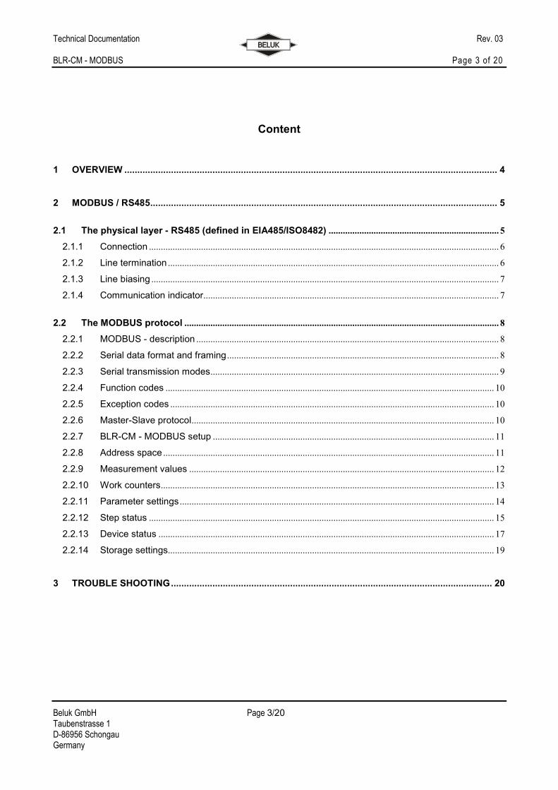
The RS485 bus interconnects more than one device (typically up to 32). To accomplish this, the several data
signals have to be interconnected for all bus devices. These are the two data lines and the common ground
GND. All devices are connected to the bus in parallel. Avoid using taps, as they tend to be the source of
transmission errors if they are too long. You should always prefer direct connection of the device to the main
bus wire.
One bus cable with all its devices is called a “bus segment”. Several segments can be interconnected by
using “repeaters”.
2.1.1 Connection
The MODBUS interface exists in two variants:
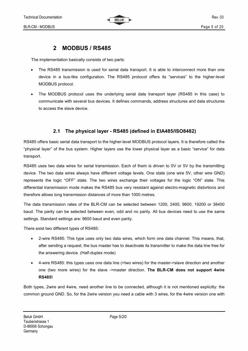
a) connection with 9-pin sub-d
PIN1 +5V (only for data line bias, do never supply any other external circuits from this voltage output!)
PIN2 GROUND for biasing and as common ground for all bus participants.
PIN5 D (B) - data signal B
PIN9 D (A) - data signal A
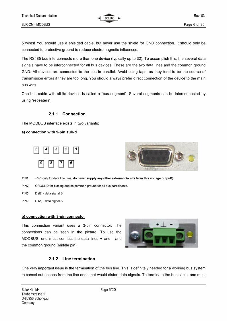
b) connection with 3-pin connector
This connection variant uses a 3-pin connector. The
connections can be seen in the picture. To use the
MODBUS, one must connect the data lines + and - and
the common ground (middle pin).
2.1.2 Line termination
One very important issue is the termination of the bus line. This is definitely needed for a working bus system
to cancel out echoes from the line ends that would distort data signals. To terminate the bus cable, one must
5 4 3 2 1
9 8 7 6
Technical Documentation Rev. 03 BLR-CM - MODBUS Page 7 of 20
Beluk GmbH Page 7/20 Taubenstrasse 1 D-86956 Schongau Germany
add a resistor at each end of the bus cable. The value of the resistor must match the cables impedance. At
most times, 120 Ω is a good value to start with. Connect the termination resistor between data wires D(+)
and D(-) at each end of the bus segment.
Some devices, especially bus converters have built-in resistors. Please check the manuals for all devices
used on the bus. If these internal resistors cannot be disabled, this has a very important influence on your
bus: you must place these devices at one of the ends of the bus! As the bus has only two ends, you can use
only two devices with fixed resistors per bus segment!
2.1.3 Line biasing
Another important issue is line biasing. If no device is actually transmitting, the data wires are left floating.
Because of the termination resistors, both will have the same voltage. This could result in spurious data
signals because of external influences. Line biasing is used to give the data wires a defined “off”-state in this
case.
Two resistors of approx. 500-600Ω have to be connected from D(+) line to +5 V and from D(-) to GND. The
two bias resistors are needed only once per bus, the position of the bias resistors is not important. They may
be placed anywhere on the bus, even in the “middle”. Please check in the manuals of all bus devices, if
resistors are internally provided!
When the device is equipped with connection variant a) (9-pin sub-d), the voltages 5V and GND are
available on the bus connector, so these two resistors can be soldered inside the connector case.
Unfortunately, this is not possible for connection variant b) (3pin). Attention at different producers the
description A = + and B = - is not correct. This has to be checked from case to case.
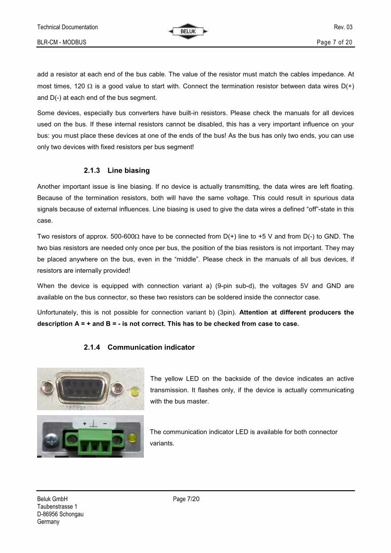
2.1.4 Communication indicator
The yellow LED on the backside of the device indicates an active
transmission. It flashes only, if the device is actually communicating
with the bus master.
The communication indicator LED is available for both connector
variants.
Technical Documentation Rev. 03 BLR-CM - MODBUS Page 8 of 20
Beluk GmbH Page 8/20 Taubenstrasse 1 D-86956 Schongau Germany
2.2 The MODBUS protocol
2.2.1 MODBUS - description
The MODBUS protocol uses the RS485 as an underlying physical layer and implements the data
transmission control mechanisms. It is therefore located on layer 2 ("link layer") of the OSI layer model for
data exchange systems.
2.2.2 Serial data format and framing
The data is transmitted in fixed frames. The frames are separated by the bus being inactive for at least 3,5
characters. All data is organized in "protocol data units" (PDUs), which are transmitted over the serial bus
system by the underlying physical protocol layer.
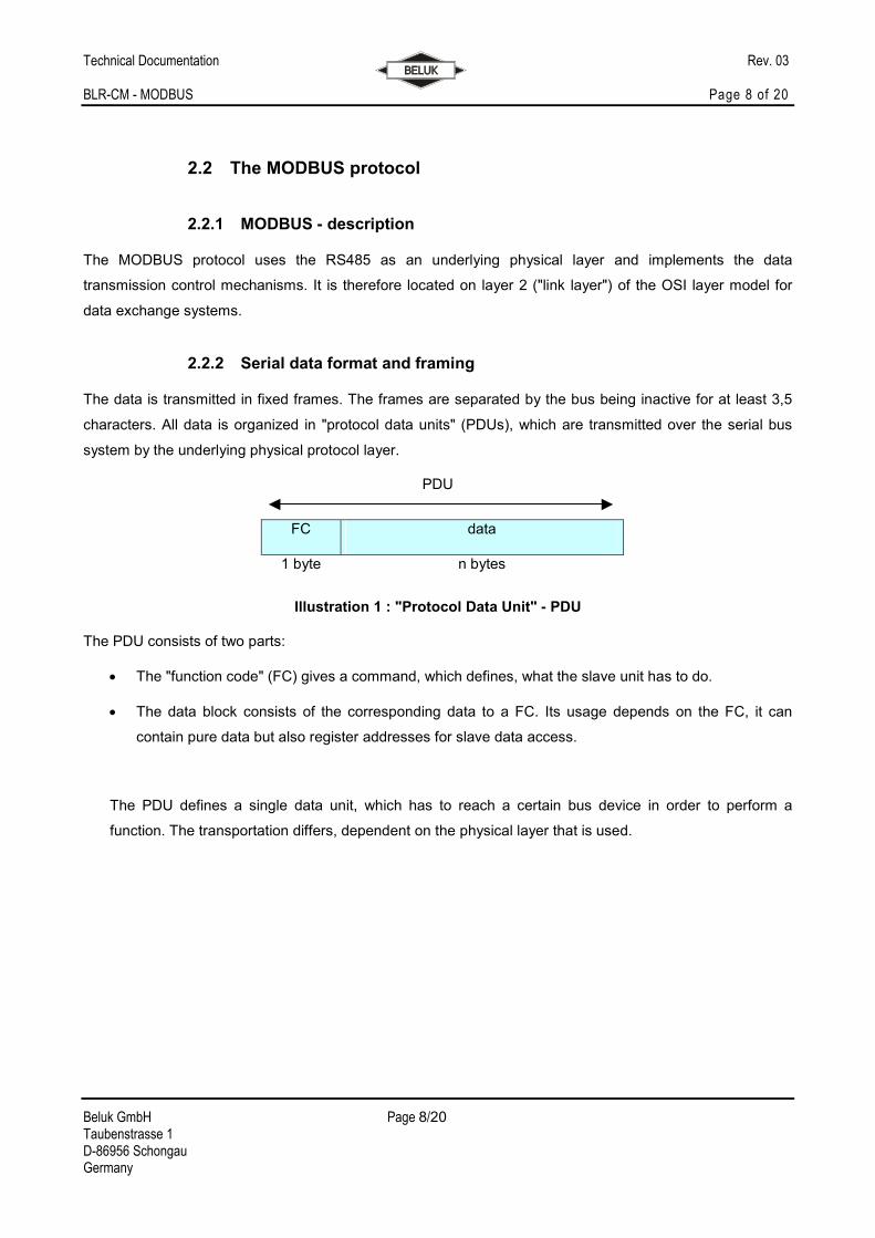
PDU
FC data
1 byte n bytes
Illustration 1 : "Protocol Data Unit" - PDU
The PDU consists of two parts:
• The "function code" (FC) gives a command, which defines, what the slave unit has to do.
• The data block consists of the corresponding data to a FC. Its usage depends on the FC, it can
contain pure data but also register addresses for slave data access.
The PDU defines a single data unit, which has to reach a certain bus device in order to perform a
function. The transportation differs, dependent on the physical layer that is used.
Technical Documentation Rev. 03 BLR-CM - MODBUS Page 9 of 20
Beluk GmbH Page 9/20 Taubenstrasse 1 D-86956 Schongau Germany
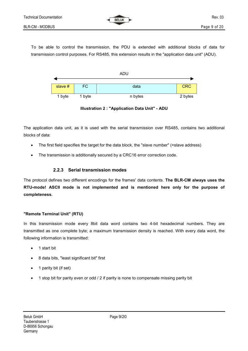
To be able to control the transmission, the PDU is extended with additional blocks of data for
transmission control purposes. For RS485, this extension results in the "application data unit" (ADU).
ADU
slave # FC data CRC
1 byte 1 byte n bytes 2 bytes
Illustration 2 : "Application Data Unit" - ADU
The application data unit, as it is used with the serial transmission over RS485, contains two additional
blocks of data:
• The first field specifies the target for the data block, the "slave number" (=slave address)
• The transmission is additionally secured by a CRC16 error correction code.
2.2.3 Serial transmission modes
The protocol defines two different encodings for the frames' data contents. The BLR-CM always uses the
RTU-mode! ASCII mode is not implemented and is mentioned here only for the purpose of
completeness.
"Remote Terminal Unit" (RTU)
In this transmission mode every 8bit data word contains two 4-bit hexadecimal numbers. They are
transmitted as one complete byte; a maximum transmission density is reached. With every data word, the
following information is transmitted:
• 1 start bit
• 8 data bits, "least significant bit" first
• 1 parity bit (if set)
• 1 stop bit for parity even or odd / 2 if parity is none to compensate missing parity bit
Technical Documentation Rev. 03 BLR-CM - MODBUS Page 10 of 20
Beluk GmbH Page 10/20 Taubenstrasse 1 D-86956 Schongau Germany
"American Standard Code for Information Interchange" (ASCII)
In ASCII-mode, the two 4-byte nibbles of an 8bit data word are transmitted separately in ASCII-code
representation. A data byte which contents 5Bhex will be divided into two parts and transmitted separately as
one byte each. The result is that TWO data bytes are transmitted with contents 35hex (=ASCII-Code "5") and
42hex (=ASCII-Code "B"). This data mode is intended for compatibility reasons and makes debugging on the
transmission line easier but it also decreases transmission speed significantly.
2.2.4 Function codes
As already mentioned, the data packet contains "function codes" which specify a command from the bus
master to the bus slave. The slave executes the command (if possible) and then answers with the same
function code in the reply to acknowledge the command. The valid range for function codes is specified from
1 to 127, but only a part of it is actually really used. Please refer to the MODBUS specifications for detailed
Information. If it is impossibly for a slave to execute a command, it replies with an exception (=an error code).
The function code of an exception packet is the function code of the received command, which caused the
error, but it was changed in a certain way: The most significant bit is set by the slave to signal the error
condition to the master. The contents of the data block specify the error in more detail.
The BLR-CM supports function codes 03hex (read holding register), 04 hex (read input register) and
06hex (write single register).
2.2.5 Exception codes
If a slave is not able to execute a command, which was sent by the master, it answers with exception codes.
A full list of codes can be found in the MODBUS specification. We do not include this list here, because the
master software will be able to handle most exceptions automatically. If one has to program the MODBUS
master stack by himself he will need the full specifications, and with that, he gets the full list of error codes.
2.2.6 Master-Slave protocol
For communication, a master-slave protocol is used. Only the bus master is permitted to initiate a transfer.
The "master" starts data exchange by sending a command to a slave by transmitting a data frame with the
corresponding function code (=command) to the slave, which will then execute it.
• The unicast-mode is normally used to communicate on a Modbus system. One single slave is
addressed by the slave number in the master’s data packet. The valid address range is between 1
and 247. The slave then executes the command and answers by sending a acknowledge data
packet back to the master.
Technical Documentation Rev. 03 BLR-CM - MODBUS Page 11 of 20
Beluk GmbH Page 11/20 Taubenstrasse 1 D-86956 Schongau Germany
• Not in any case the master can receive an answer to his query: in multicast-mode all slaves on the
bus are addressed in parallel. They all execute the same command, but none of them will respond.
The master initiates a multicast transfer by using "0" as slave number.
2.2.7 BLR-CM - MODBUS setup
If your device has MODBUS support, an additional entry is available in the “setup” - menu of the device.
After entering it, you will have the possibility to select the following items:
• ADDRESS: This is the devices slave address (slave ID). The valid range is 1-247.
• BAUD RATE: Select the baud rate here. The valid range is 1200 - 38400 baud.
• PARITY: Select the parity to be 8none2, 8even1 or 8odd1 (data bit/parity/stop bit).
The settings for baud rate and parity must be the same for all bus devices; the address must be unique for
each device.
2.2.8 Address space
The data in the BLR-CM is organized and accessed by means of addresses. Each address accesses one
data word. The data words are always 16bits wide.
The BLR-CM does not differentiate the addresses between the function codes. There is one big address
space available and to access each address’s data, any valid function code can be used. Nevertheless, the
data will only make sense when interpreted the correct way!
The data can be of the following types:
• REAL: this is a 32 bit floating-point number, as defined in IEEE Standard 754.
• UINT16: this is an unsigned 16 bit integer value.
• UINT32, SINT32: this is an unsigned/signed 32 bit integer value.
As the data is organized in 16 bit wide words, a set of sequential addresses has to be read for longer data
items. For these, the base address is given in the tables. To read a REAL with base address 12, one has to
read two 16bit words from addresses 12 and 13. These two values need to be concatenated to form the
desired result of 32 bits. Most SCADA software packages or PLCs can do this task for you.
Technical Documentation Rev. 03 BLR-CM - MODBUS Page 12 of 20
Beluk GmbH Page 12/20 Taubenstrasse 1 D-86956 Schongau Germany
There exist different types of addresses:
• The MODBUS address always starts with 0 and can go up to 65535. It can be used
with any function code.
• Certain PLCs lack correct handling of the 0 and therefore add 1 to the address. So their
addresses (MODBUS address +1) always start with 1.
• Some SCADA tools add an offset to determine the function code, which shall be used to
access the device at the given address. They also sometimes add 1 to the MOSBUS address.
As an example, address 40001 would be “read MODBUS address 0 with function code 03hex”,
30012 would be “read MODBUS address 11 with function code 04hex”.
Please refer to your software’s manual to find out the correct addresses.
The following tables always give the MODBUS addresses mentioned first in above list.
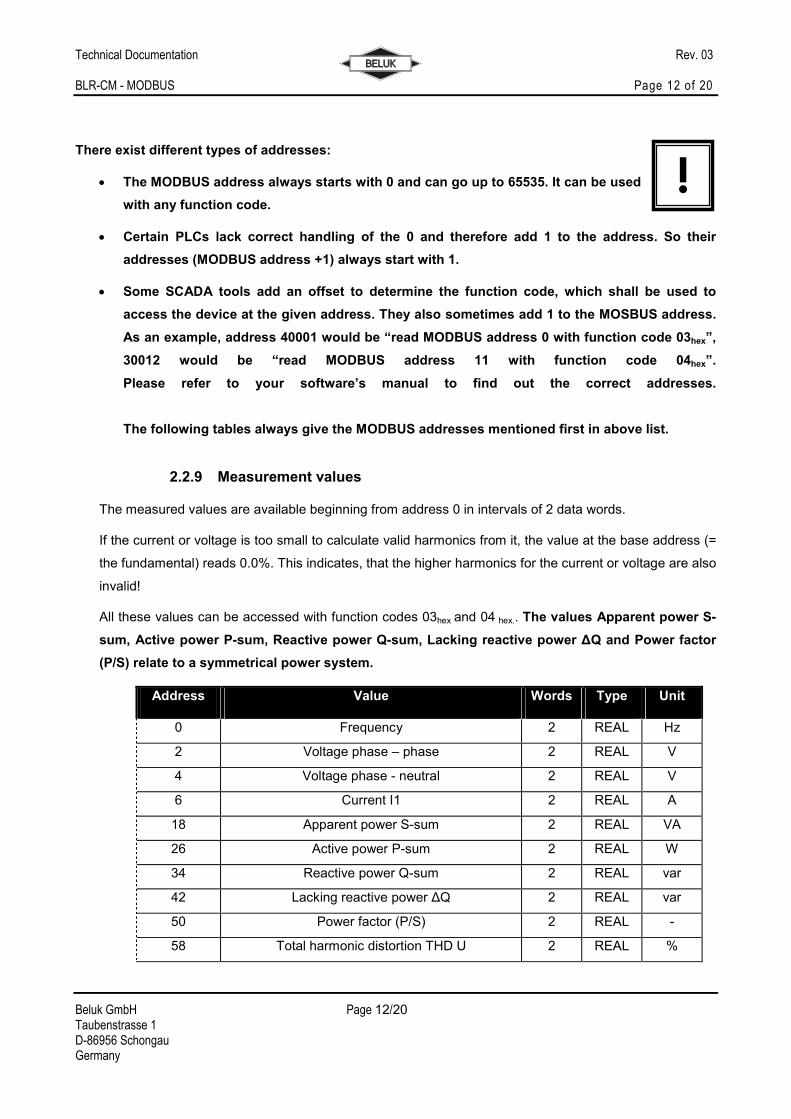
2.2.9 Measurement values
The measured values are available beginning from address 0 in intervals of 2 data words.
If the current or voltage is too small to calculate valid harmonics from it, the value at the base address (=
the fundamental) reads 0.0%. This indicates, that the higher harmonics for the current or voltage are also
invalid!
All these values can be accessed with function codes 03hex and 04 hex.. The values Apparent power S-
sum, Active power P-sum, Reactive power Q-sum, Lacking reactive power ∆Q and Power factor
(P/S) relate to a symmetrical power system.
Address Value Words Type Unit
0 Frequency 2 REAL Hz
2 Voltage phase – phase 2 REAL V
4 Voltage phase - neutral 2 REAL V
6 Current I1 2 REAL A
18 Apparent power S-sum 2 REAL VA
26 Active power P-sum 2 REAL W
34 Reactive power Q-sum 2 REAL var
42 Lacking reactive power ∆Q 2 REAL var
50 Power factor (P/S) 2 REAL -
58 Total harmonic distortion THD U 2 REAL %
!
Technical Documentation Rev. 03 BLR-CM - MODBUS Page 13 of 20
Beluk GmbH Page 13/20 Taubenstrasse 1 D-86956 Schongau Germany
60 Harmonics U 1. order = fundamental wave 2 REAL %
62 Harmonics U 2. order 2 REAL %
64 Harmonics U 3. order 2 REAL %
…
122 Harmonics U 32. order 2 REAL %
124 Total harmonic distortion THD I 2 REAL %
130 Harmonics I 1. order = fundamental wave 2 REAL %
132 Harmonics I 2. order 2 REAL %
134 Harmonics I 3. order 2 REAL %
…
192 Harmonics I 32. order 2 REAL %
322 Ambient temperature 2 REAL °C
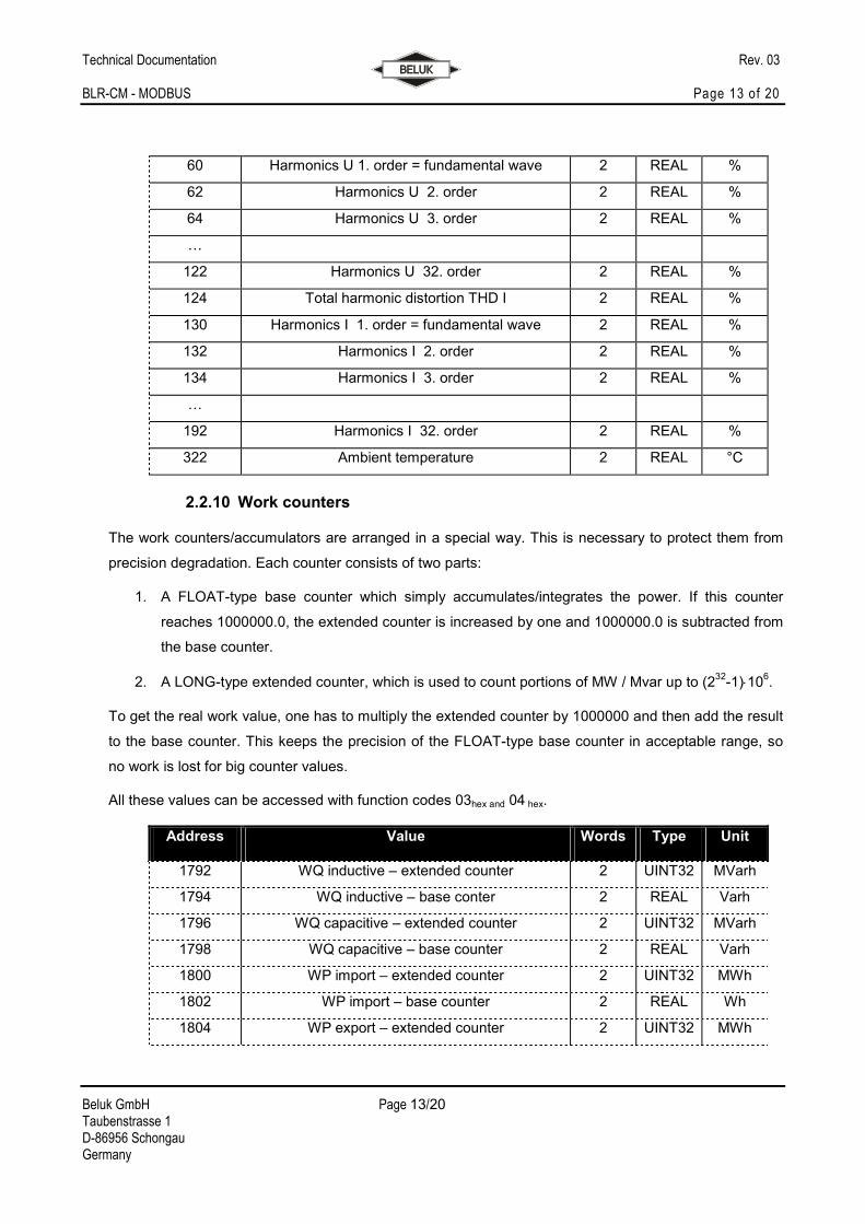
2.2.10 Work counters
The work counters/accumulators are arranged in a special way. This is necessary to protect them from
precision degradation. Each counter consists of two parts:
1. A FLOAT-type base counter which simply accumulates/integrates the power. If this counter
reaches 1000000.0, the extended counter is increased by one and 1000000.0 is subtracted from
the base counter.
2. A LONG-type extended counter, which is used to count portions of MW / Mvar up to (232-1)⋅10
6.
To get the real work value, one has to multiply the extended counter by 1000000 and then add the result
to the base counter. This keeps the precision of the FLOAT-type base counter in acceptable range, so
no work is lost for big counter values.
All these values can be accessed with function codes 03hex and 04 hex.
Address Value Words Type Unit
1792 WQ inductive – extended counter 2 UINT32 MVarh
1794 WQ inductive – base conter 2 REAL Varh
1796 WQ capacitive – extended counter 2 UINT32 MVarh
1798 WQ capacitive – base counter 2 REAL Varh
1800 WP import – extended counter 2 UINT32 MWh
1802 WP import – base counter 2 REAL Wh
1804 WP export – extended counter 2 UINT32 MWh
Technical Documentation Rev. 03 BLR-CM - MODBUS Page 14 of 20
Beluk GmbH Page 14/20 Taubenstrasse 1 D-86956 Schongau Germany
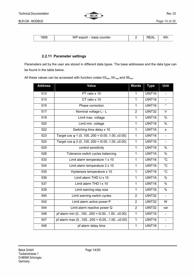
1806 WP export – base counter 2 REAL Wh
2.2.11 Parameter settings
Parameters set by the user are stored in different data types. The base addresses and the data type can
be found in the table below.
All these values can be accessed with function codes 03hex, 04 hex and 06hex.
Address Value Words Type Unit
512 PT ratio x 10 1 UINT16 -
513 CT ratio x 10 1 UINT16 -
515 Phase correction 1 UINT16 °
517 Nominal voltage L - L 2 UINT32 V
519 Limit max. voltage 1 UINT16 %
520 Limit min. voltage 1 UINT16 %
522 Switching time delay x 10 1 UINT16 s
523 Target cos φ 1 (0..100..200 = i0.00..1.00..c0.00) 1 UINT16 -
524 Target cos φ 2 (0..100..200 = i0.00..1.00..c0.00) 1 UINT16 -
525 control sensitivity 1 UINT16 %
526 Tolerance switch cycles balancing 1 UINT16 %
533 Limit alarm temperature 1 x 10 1 UINT16 °C
534 Limit alarm temperature 2 x 10 1 UINT16 °C
535 Hysteresis temperature x 10 1 UINT16 °C
536 Limit alarm THD U x 10 1 UINT16 %
537 Limit alarm THD I x 10 1 UINT16 %
539 Limit warning step size 1 UINT16 %
540 Limit warning switch cycles 2 UINT32 -
542 Limit alarm active power P 2 UINT32 W
544 Limit alarm reactive power Q 2 UINT32 var
546 pf alarm min (0...100...200 = i0.00...1.00...c0.00) 1 UINT16 -
547 pf alarm max (0...100...200 = i0.00...1.00...c0.00) 1 UINT16 -
548 pf alarm delay time 1 UINT16 -
Technical Documentation Rev. 03 BLR-CM - MODBUS Page 15 of 20
Beluk GmbH Page 15/20 Taubenstrasse 1 D-86956 Schongau Germany
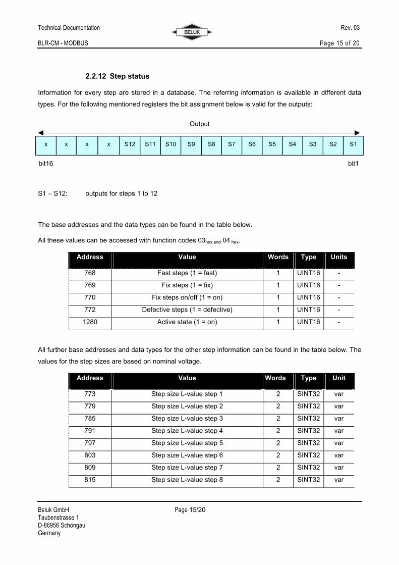
2.2.12 Step status
Information for every step are stored in a database. The referring information is available in different data
types. For the following mentioned registers the bit assignment below is valid for the outputs:
Output
x x x x S12 S11 S10 S9 S8 S7 S6 S5 S4 S3 S2 S1
bit16 bit1
S1 – S12: outputs for steps 1 to 12
The base addresses and the data types can be found in the table below.
All these values can be accessed with function codes 03hex and 04 hex.
Address Value Words Type Units
768 Fast steps (1 = fast) 1 UINT16 -
769 Fix steps (1 = fix) 1 UINT16 -
770 Fix steps on/off (1 = on) 1 UINT16 -
772 Defective steps (1 = defective) 1 UINT16 -
1280 Active state (1 = on) 1 UINT16 -
All further base addresses and data types for the other step information can be found in the table below. The
values for the step sizes are based on nominal voltage.
Address Value Words Type Unit
773 Step size L-value step 1 2 SINT32 var
779 Step size L-value step 2 2 SINT32 var
785 Step size L-value step 3 2 SINT32 var
791 Step size L-value step 4 2 SINT32 var
797 Step size L-value step 5 2 SINT32 var
803 Step size L-value step 6 2 SINT32 var
809 Step size L-value step 7 2 SINT32 var
815 Step size L-value step 8 2 SINT32 var
Technical Documentation Rev. 03 BLR-CM - MODBUS Page 16 of 20
Beluk GmbH Page 16/20 Taubenstrasse 1 D-86956 Schongau Germany
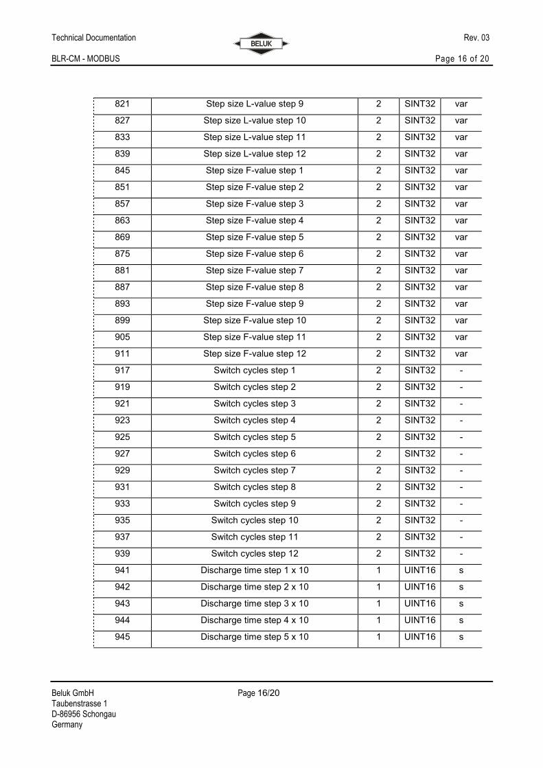
821 Step size L-value step 9 2 SINT32 var
827 Step size L-value step 10 2 SINT32 var
833 Step size L-value step 11 2 SINT32 var
839 Step size L-value step 12 2 SINT32 var
845 Step size F-value step 1 2 SINT32 var
851 Step size F-value step 2 2 SINT32 var
857 Step size F-value step 3 2 SINT32 var
863 Step size F-value step 4 2 SINT32 var
869 Step size F-value step 5 2 SINT32 var
875 Step size F-value step 6 2 SINT32 var
881 Step size F-value step 7 2 SINT32 var
887 Step size F-value step 8 2 SINT32 var
893 Step size F-value step 9 2 SINT32 var
899 Step size F-value step 10 2 SINT32 var
905 Step size F-value step 11 2 SINT32 var
911 Step size F-value step 12 2 SINT32 var
917 Switch cycles step 1 2 SINT32 -
919 Switch cycles step 2 2 SINT32 -
921 Switch cycles step 3 2 SINT32 -
923 Switch cycles step 4 2 SINT32 -
925 Switch cycles step 5 2 SINT32 -
927 Switch cycles step 6 2 SINT32 -
929 Switch cycles step 7 2 SINT32 -
931 Switch cycles step 8 2 SINT32 -
933 Switch cycles step 9 2 SINT32 -
935 Switch cycles step 10 2 SINT32 -
937 Switch cycles step 11 2 SINT32 -
939 Switch cycles step 12 2 SINT32 -
941 Discharge time step 1 x 10 1 UINT16 s
942 Discharge time step 2 x 10 1 UINT16 s
943 Discharge time step 3 x 10 1 UINT16 s
944 Discharge time step 4 x 10 1 UINT16 s
945 Discharge time step 5 x 10 1 UINT16 s
Technical Documentation Rev. 03 BLR-CM - MODBUS Page 17 of 20
Beluk GmbH Page 17/20 Taubenstrasse 1 D-86956 Schongau Germany
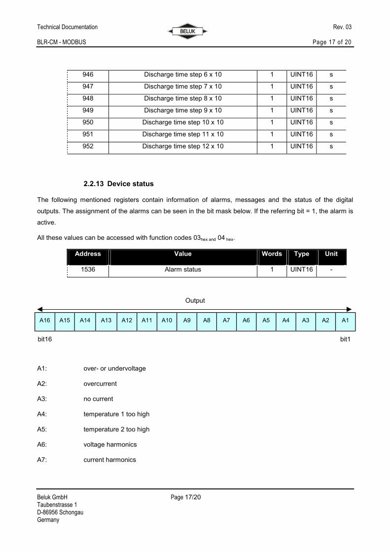
946 Discharge time step 6 x 10 1 UINT16 s
947 Discharge time step 7 x 10 1 UINT16 s
948 Discharge time step 8 x 10 1 UINT16 s
949 Discharge time step 9 x 10 1 UINT16 s
950 Discharge time step 10 x 10 1 UINT16 s
951 Discharge time step 11 x 10 1 UINT16 s
952 Discharge time step 12 x 10 1 UINT16 s
2.2.13 Device status
The following mentioned registers contain information of alarms, messages and the status of the digital
outputs. The assignment of the alarms can be seen in the bit mask below. If the referring bit = 1, the alarm is
active.
All these values can be accessed with function codes 03hex and 04 hex.
Address Value Words Type Unit
1536 Alarm status 1 UINT16 -
Output
A16 A15 A14 A13 A12 A11 A10 A9 A8 A7 A6 A5 A4 A3 A2 A1
bit16 bit1
A1: over- or undervoltage
A2: overcurrent
A3: no current
A4: temperature 1 too high
A5: temperature 2 too high
A6: voltage harmonics
A7: current harmonics
Technical Documentation Rev. 03 BLR-CM - MODBUS Page 18 of 20
Beluk GmbH Page 18/20 Taubenstrasse 1 D-86956 Schongau Germany
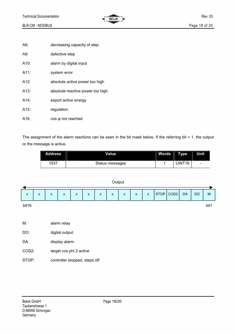
A8: decreasing capacity of step
A9: defective step
A10: alarm by digital input
A11: system error
A12: absolute active power too high
A13: absolute reactive power too high
A14: export active energy
A15: regulation
A16: cos φ not reached
The assignment of the alarm reactions can be seen in the bit mask below. If the referring bit = 1, the output
or the message is active.
Address Value Words Type Unit
1537 Status messages 1 UINT16 -
Output
x x x x x x x x x x x STOP COS2 DA DO M
bit16 bit1
M: alarm relay
DO: digital output
DA: display alarm
COS2: target cos phi 2 active
STOP: controller stopped, steps off
Technical Documentation Rev. 03 BLR-CM - MODBUS Page 19 of 20
Beluk GmbH Page 19/20 Taubenstrasse 1 D-86956 Schongau Germany
All settings send by MODBUS are used immediately, but remember that this information
is only stored in the working memory. After a power blackout these settings will be lost.
To store the settings durable, you have to store the data in the non-volatile memory.
2.2.14 Storage settings
For storing the settings durable in the non-volatile storage (EPROM) you have to use the table below.
All these values can be accessed with function codes 03hex, 04 hex and 06hex.
Address Value Words Type Unit
4096 Store parameter data in EPROM 1 UINT16 -
If you write “29864” to the above address the parameter data will be stored durable in the EPROM. After the
correct takeover this is confirmed by “1” in the same register.
This action should not be done permanently or too often, because the lifetime of the flash storage is limited!
There are other values present in the devices memory than the ones mentioned above.
They can contain important setup data for the device. Do never write to any address if
you’re not sure what data it contains!
!
!
Technical Documentation Rev. 03 BLR-CM - MODBUS Page 20 of 20
Beluk GmbH Page 20/20 Taubenstrasse 1 D-86956 Schongau Germany
3 Trouble shooting
If the bus connection isn’t working correctly, please check the following points:
1. If there is no communication at all, then the error must be looked for between the BLR-CM and the
PC!
Possible causes can be:
- Check adjustment of baud rate, parity and address at the BLR-CM, possibly make
changes in the configuration
- Possibly the bus lines A and B are interchanged, if necessary rectify
- Check adjustments of the converter RS485/RS232, possibly use the data sheet of the
converter
- Perhaps the port is already used by another application, if necessary stop this multiple
reservation
- Check termination and bias resistors, if necessary rectify
2. Does the cable of the bus connection have any damages? All plug connections are correct? If
necessary replace.
3. Is the pin assignment of the RS485 connection correct? If necessary rectify.
4. The shielding of the bus line must not be connected with the ground of the bus. But the shielding
should be connected to protective ground. If necessary rectify.
5. Is the communication possible, but there are problems with the software of the customer, then
please check the following points:
- Check adjustment of bus address, parity and baud rate in the software
- Check data format