Embed Size (px)
Citation preview
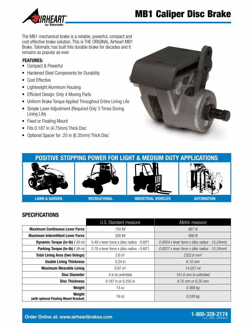
MB1 Caliper Disc Brake
Order Online at: www.airheartbrakes.com 1-800-328-2174U.S. AND CANADA
SPECIFICATIONSU.S. Standard measure Metric measure
Maximum Continuous Lever Force 150 lbf 667 N
Maximum Intermittent Lever Force 200 lbf 890 N
Dynamic Torque (in-lb) / (N-m) 5.40 x lever force x (disc radius - 0.60") 0.0054 x lever force x (disc radius - 15.24mm)
Parking Torque (in-lb) / (N-m) 2.70 x lever force x (disc radius - 0.60") 0.0027 x lever force x (disc radius - 15.24mm)
Total Lining Area (two linings) 3.6 in2 2322.6 mm2
Usable Lining Thickness 0.24 in 6.10 mm
Maximum Wearable Lining 0.87 in3 14.257 ml
Disc Diameter 4 in to unlimited 101.6 mm to unlimited
Disc Thickness 0.187 in or 0.250 in 4.75 mm or 6.35 mm
Weight 13 oz 0.369 kg
Weight (with optional Floating Mount Bracket) 19 oz 0.539 kg
POSITIVE STOPPING POWER FOR LIGHT & MEDIUM DUTY APPLICATIONS
LAWN & GARDEN RECREATIONAL INDUSTRIAL VEHICLES AUTOMATION
The MB1 mechanical brake is a reliable, powerful, compact and cost effective brake solution. This is THE ORIGINAL Airheart MB1 Brake. Tolomatic has built this durable brake for decades and it remains as popular as ever.
FEATURES:• Compact & Powerful
• Hardened Steel Components for Durability
• Cost Effective
• Lightweight Aluminum Housing
• Efficient Design: Only 4 Moving Parts
• Uniform Brake Torque Applied Throughout Entire Lining Life
• Simple Lever Adjustment (Required Only 3 Times During Lining Life)
• Fixed or Floating Mount
• Fits 0.187 in (4.75mm) Thick Disc
• Optional Spacer for .25 in (6.35mm) Thick Disc
MB1 Caliper Disc Brake
3800 County Road 116 • Hamel, MN 55340, U.S.A. Phone: (763) 478-8000 • Fax: (763) 478-8080 www.airheartbrakes.com • Email: [email protected]
All brand, product and corporate names are trademarks of their respective owners, and are used only for explana-tion and to the owner’s benefit, without intent to infringe.Information furnished in this catalog is believed to be accurate and reliable at the time of printing. However, Tolo-matic assumes no responsibility for its use or for any errors that may appear in this document. Tolomatic reserves the right to change the design or operation of the equipment described herein and any associated motion products without notice. Information in this document is subject to change without notice.
© 2014 Tolomatic 201404231101
Toll-Free:1-800-328-2174U.S. AND CANADA
LITERATURE NUMBER: 3999-4106_01
4.00 (101.6)
2.94 (74.7)3.50 (88.9)
2.31 (58.7)
2.00 (50.8)1.00
(25.4)
0.28 (7.1) DIA.THRU 2 HOLES
1.19(30.2)
1.81(46.0) 2.69
(68.3)
1.05(26.7)
2.00 (50.8)
1.00(25.4)
0.65(16.5)
0.14(3.6)
3.75 (95.3)
2.56 (65.0)
CL OF DISC& MOUNTINGHOLES
LEVER POSITIONS12 O’CLOCK
9 O’CLOCK
6 O’CLOCK
3 O’CLOCK
CCW PULL
CCW PULL
CW PULL
CW PULL
CW PULL
CW PULL
CCW PULL
CCW PULL
1.19 (30.2)TRAVEL
1.56 (39.6)TRAVEL
3.00 R (76.2) TYP.
3.00 R (76.2) TYP.
2.31 R (58.7) TYP.
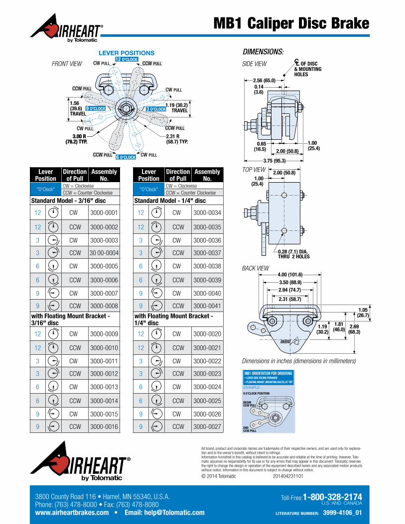
Lever Position
Direction of Pull
Assembly No.
"O'Clock"CW = ClockwiseCCW = Counter Clockwise
Standard Model - 3/16" disc
12 CW 3000-0001
12 CCW 3000-0002
3 CW 3000-0003
3 CCW 30 00-0004
6 CW 3000-0005
6 CCW 3000-0006
9 CW 3000-0007
9 CCW 3000-0008
with Floating Mount Bracket - 3/16" disc
12 CW 3000-0009
12 CCW 3000-0010
3 CW 3000-0011
3 CCW 3000-0012
6 CW 3000-0013
6 CCW 3000-0014
9 CW 3000-0015
9 CCW 3000-0016
Lever Position
Direction of Pull
Assembly No.
"O'Clock"CW = ClockwiseCCW = Counter Clockwise
Standard Model - 1/4" disc
12 CW 3000-0034
12 CCW 3000-0035
3 CW 3000-0036
3 CCW 3000-0037
6 CW 3000-0038
6 CCW 3000-0039
9 CW 3000-0040
9 CCW 3000-0041
with Floating Mount Bracket - 1/4" disc
12 CW 3000-0020
12 CCW 3000-0021
3 CW 3000-0022
3 CCW 3000-0023
6 CW 3000-0024
6 CCW 3000-0025
9 CW 3000-0026
9 CCW 3000-0027
MB1 ORIENTATION FOR ORDERING• LEVER SIDE FACING FORWARD• FLOATING MOUNT (MOUNTING BOLTS) AT TOP
EXAMPLE
9 O’CLOCK POSITION
BEGIN CCW PULL
END CCW PULL
4.00 (101.6)
2.94 (74.7)3.50 (88.9)
2.31 (58.7)
2.00 (50.8)1.00
(25.4)
0.28 (7.1) DIA.THRU 2 HOLES
1.19(30.2)
1.81(46.0) 2.69
(68.3)
1.05(26.7)
2.00 (50.8)
1.00(25.4)
0.65(16.5)
0.14(3.6)
3.75 (95.3)
2.56 (65.0)
CL OF DISC& MOUNTINGHOLES
LEVER POSITIONS12 O’CLOCK
9 O’CLOCK
6 O’CLOCK
3 O’CLOCK
CCW PULL
CCW PULL
CW PULL
CW PULL
CW PULL
CW PULL
CCW PULL
CCW PULL
1.19 (30.2)TRAVEL
1.56 (39.6)TRAVEL
3.00 R (76.2) TYP.
3.00 R (76.2) TYP.
2.31 R (58.7) TYP.
DIMENSIONS:
Dimensions in inches (dimensions in millimeters)
SIDE VIEWFRONT VIEW
TOP VIEW
BACK VIEW