Embed Size (px)
Citation preview
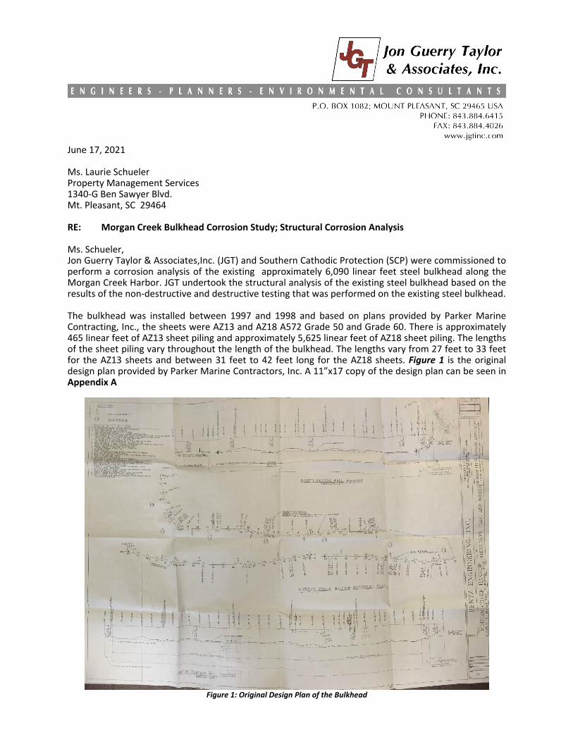
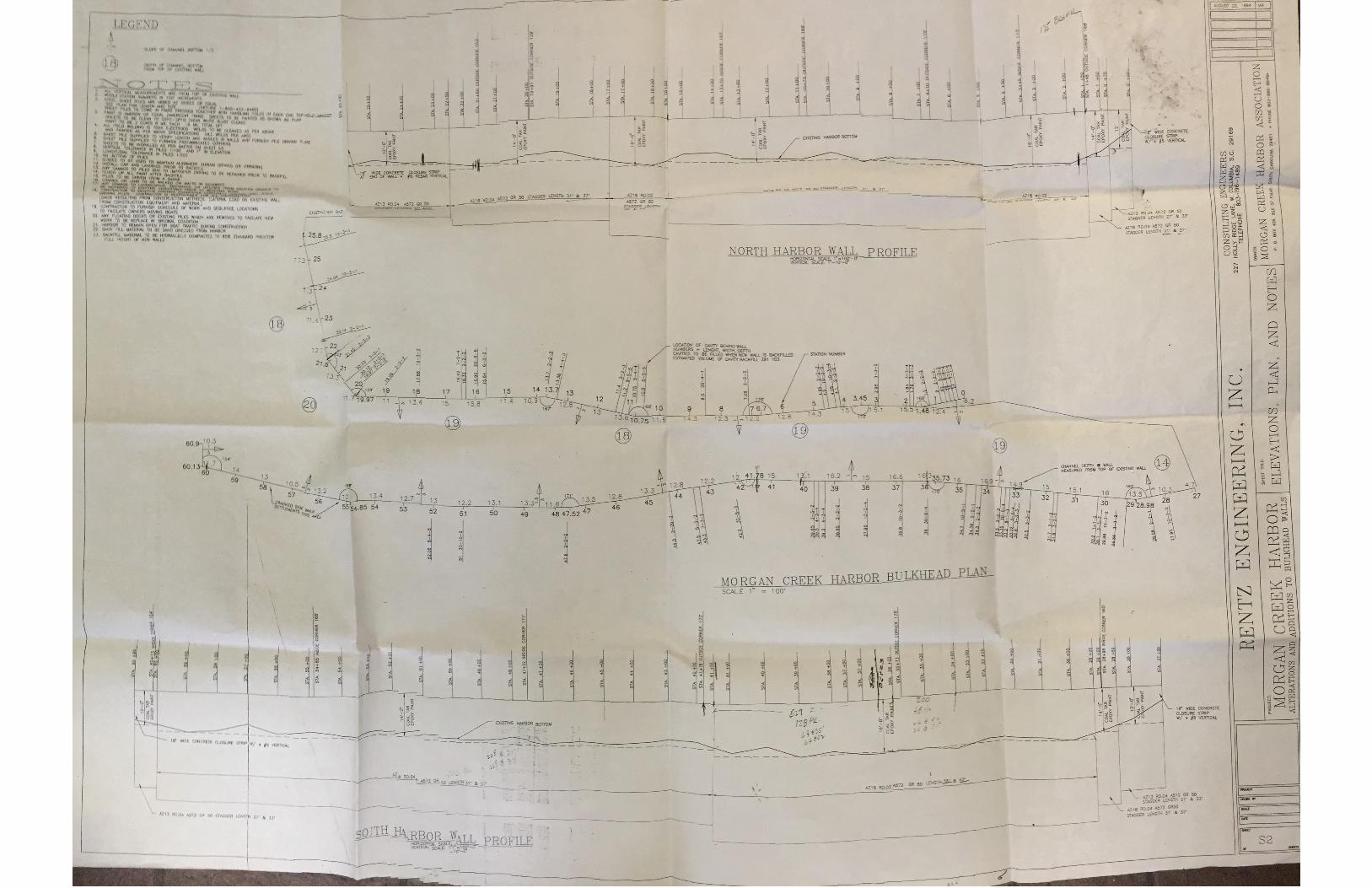
June 17, 2021 Ms. Laurie Schueler Property Management Services 1340‐G Ben Sawyer Blvd. Mt. Pleasant, SC 29464 RE: Morgan Creek Bulkhead Corrosion Study; Structural Corrosion Analysis Ms. Schueler, Jon Guerry Taylor & Associates,Inc. (JGT) and Southern Cathodic Protection (SCP) were commissioned to perform a corrosion analysis of the existing approximately 6,090 linear feet steel bulkhead along the Morgan Creek Harbor. JGT undertook the structural analysis of the existing steel bulkhead based on the results of the non‐destructive and destructive testing that was performed on the existing steel bulkhead. The bulkhead was installed between 1997 and 1998 and based on plans provided by Parker Marine Contracting, Inc., the sheets were AZ13 and AZ18 A572 Grade 50 and Grade 60. There is approximately 465 linear feet of AZ13 sheet piling and approximately 5,625 linear feet of AZ18 sheet piling. The lengths of the sheet piling vary throughout the length of the bulkhead. The lengths vary from 27 feet to 33 feet for the AZ13 sheets and between 31 feet to 42 feet long for the AZ18 sheets. Figure 1 is the original design plan provided by Parker Marine Contractors, Inc. A 11”x17 copy of the design plan can be seen in Appendix A
Figure 1: Original Design Plan of the Bulkhead

MC Corrosion Structural Report
The AZ18 and AZ13 sheet pile properties are as follows (Table A): Table A:
Section Width (in)
Height (in)
Flange thickness
(in)
Web Thickness
(in)
Section area
(in^2/ft)
Elastic Modulus (in^3/ft)
Moment of Inertia (in^4/ft)
AZ13 26.38 11.93 0.375 0.375 6.47 24.2 144.3
AZ18 24.80 14.96 0.375 0.375 7.11 33.5 250.4
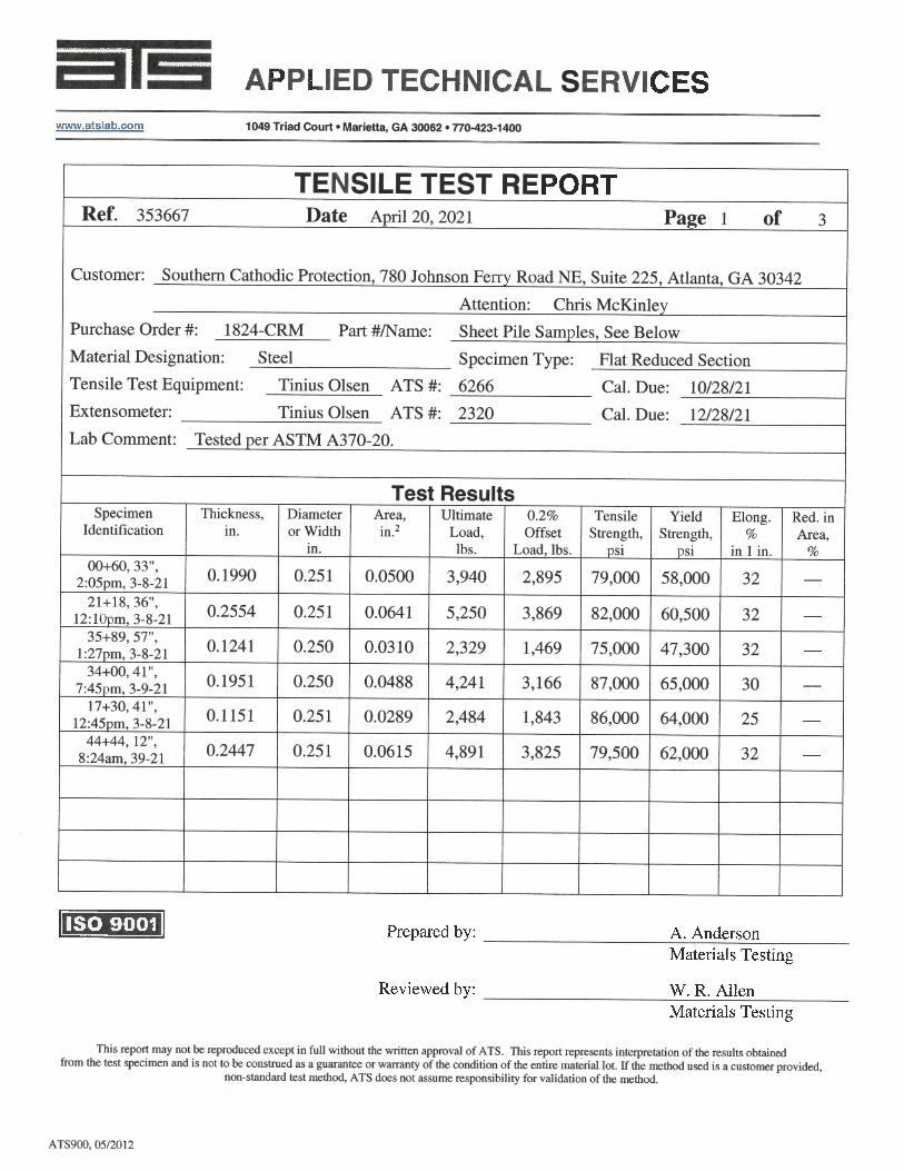
As shown on the plans, the AZ13 sheets were A572 Grade 50 KSI steel and the AZ18 sheets were A572 Grade 50 KSI and 60 KSI steel (KSI is Kips per square inch, 1 kip equals 1000 lbs; therefore, a grade or yield strength of 50 KSI equals 50,000 PSI steel). The destructive testing involved removing a 4‐inch diameter sample of the steel bulkhead sheet at six (6) locations proposed by SPC. These samples were removed and sent to a lab for testing. The locations were as follows (Table B): Table B:
Station along wall Sta 0+60 Sta 17+30 Sta 21+18 Sta 34+00 Sta 35+89 Sta 44+44
Sample location below the cap.
33 inches 41 inches 36 inches 41 inches 57 inches 12 inches
Sheet AZ13 AZ18 AZ18 AZ18 AZ18 AZ18
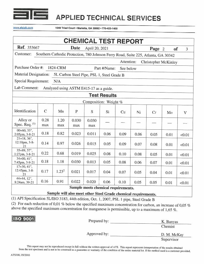
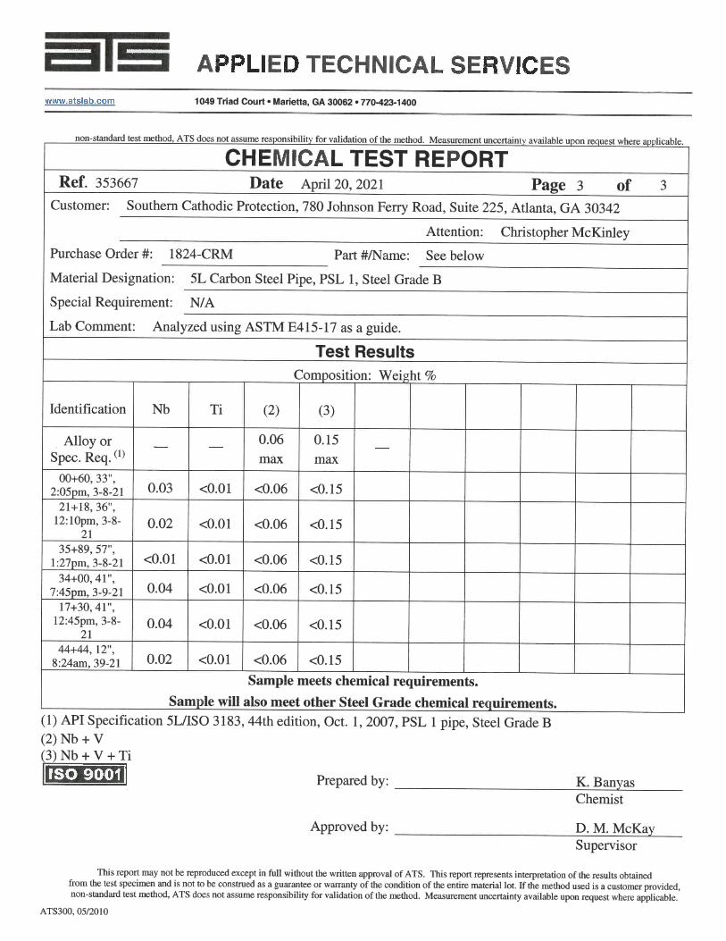
The destructive tested analyzed the structural (tensile) and chemical make‐up of the samples removed from the existing sheets. The test results can be found in Appendix B of this report. STRUCTUAL ANALYSIS JGT used the information from the tensile test report (found in Appendix B) to approximate the existing structural capacity of the bulkhead. JGT used the section profile of the AZ18 sheet as a basis for the analysis of the AZ18 sheets. A digital version of the AZ13 sheet section could not be found so an analysis of the AZ13 sheet was not completed. Outlined below is a summary of the Tensile Test Results of the steel coupons (Table C) Table C:
Location Thickness (in) Area (in^2) Ultimate Load
(lbs) Yield Strength (PSI)
Original 0.375 ‐ ‐ 50,000 or 60,000
0+60 0.1990 0.05 3,940 58,000
17+30 0.1151 0.0289 2,484 64,000
21+18 0.2554 0.0641 5,250 60,500
34+00 0.1951 0.0488 4,241 65,000
35+89 0.1241 0.031 2,329 47,300
44+44 0.2447 0.0615 4,891 62,000
The AZ18 section was used to determine the existing properties of the sheets based on the testing data and thickness determination of the coupons. Assumptions were made to complete the analysis. Based on the thickness as determined from the testing, it was assumed that the entire sheet section and
MC Corrosion Structural Report
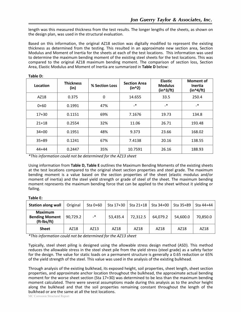
length was this measured thickness from the test results. The longer lengths of the sheets, as shown on the design plan, was used in the structural evaluation. Based on this information, the original AZ18 section was digitally modified to represent the existing thickness as determined from the testing. This resulted in an approximate new section area, Section Modulus and Moment of Inertia for the sheets at each of the test locations. This information was used to determine the maximum bending moment of the existing steel sheets for the test locations. This was compared to the original AZ18 maximum bending moment. The comparison of section loss, Section Area, Elastic Modulus and Moment of Inertia are summarized in Table D below: Table D:
Location Thickness
(in) % Section Loss
Section Area (in^2)
Elastic Modulus (in^3/ft)
Moment of Inertia (in^4/ft)
AZ18 0.375 0 14.655 33.5 250.4
0+60 0.1991 47% ‐* ‐* ‐*
17+30 0.1151 69% 7.1676 19.73 134.8
21+18 0.2554 32% 11.06 26.71 193.48
34+00 0.1951 48% 9.373 23.66 168.02
35+89 0.1241 67% 7.4138 20.16 138.55
44+44 0.2447 35% 10.7591 26.16 188.93
*This information could not be determined for the AZ13 sheet Using information from Table D, Table E outlines the Maximum Bending Moments of the existing sheets at the test locations compared to the original sheet section properties and steel grade. The maximum bending moment is a value based on the section properties of the sheet (elastic modulus and/or moment of inertia) and the steel yield strength or grade of steel of the sheet. The maximum bending moment represents the maximum bending force that can be applied to the sheet without it yielding or failing. Table E:
Station along wall Original Sta 0+60 Sta 17+30 Sta 21+18 Sta 34+00 Sta 35+89 Sta 44+44
Maximum Bending Moment
(ft‐lbs/ft) 90,729.2 ‐* 53,435.4 72,312.5 64,079.2 54,600.0 70,850.0
Sheet AZ18 AZ13 AZ18 AZ18 AZ18 AZ18 AZ18
*This information could not be determined for the AZ13 sheet Typically, steel sheet piling is designed using the allowable stress design method (ASD). This method reduces the allowable stress in the steel sheet pile from the yield stress (steel grade) as a safety factor for the design. The value for static loads on a permanent structure is generally a 0.65 reduction or 65% of the yield strength of the steel. This value was used in the analysis of the existing bulkhead. Through analysis of the existing bulkhead, its exposed height, soil properties, sheet length, sheet section properties, and approximate anchor location throughout the bulkhead, the approximate actual bending moment for the worse sheet section (Sta 17+30) was determined to be less than the maximum bending moment calculated. There were several assumptions made during this analysis as to the anchor height along the bulkhead and that the soil properties remaining constant throughout the length of the bulkhead or are the same at all the test locations.
MC Corrosion Structural Report
The shear strength of the steel at these test locations could not be determined accurately given some of the unknowns at the anchor locations and anchors not necessarily located at the test locations. The shear strength of the steel would represent the force needed to pull through the steel sheet. SUMMARY While the steel sheets have experienced significant section loss due to corrosion of the steel, the steel sheets remain structurally stable based on the assumptions made, the estimated steel section properties and the completed analysis. Much of this structural stability could be due to the grades of steel used for the steel piling. The higher (50KSI and 60KSI) grades of steel are stronger than lower grades of steel. However, these test samples only represent six locations along the bulkhead at the specific heights from the cap outlined. There may be other areas along the 6,090 linear feet of bulkhead where the steel is thinner and the section properties are less. Penetrations in the steel sheets of the bulkhead have been found in small localized locations. In these areas the steel thickness would be much less than determined in the test samples. The worse test area was at Sta 17+30 where the sample thickness was 0.1151 inches and represented a section loss in that area of approximately 69% compared to the original thickness. Further corrosion of the sheets will continue to lessen the structural strength of the steel sheets and the bulkhead in general. While the section loss does vary between 32% and 69%, there is no visible pattern to the amount of section loss that has occurred since the bulkhead was installed. In reviewing the recommendations from the corrosion analysis report by SCP, JGT would also recommend a cathodic protection system to eliminate any further corrosion of the steel sheets. By eliminating further corrosion, the structural stability of the steel sheets and the bulkhead would remain stable and would not continue to decrease due to continued corrosion of the steel. The other recommendation option consider would be the full replacement of the steel sheet pile bulkhead with a properly designed and properly coated (on both the front and back of the sheets) bulkhead. This option would be much more expensive that the installation of a cathodic protection system. Should you have any questions or comments concerning this report, please feel free to let us know. Sincerely, JON GUERRY TAYLOR & ASSOCIATES, INC.
Christopher W. Moore, PE President/Principle Engineer
MC Corrosion Structural Report
Appendix A

MC Corrosion Structural Report
Appendix B