Embed Size (px)
Citation preview
McIntosh Laboratory, Inc. 2 Chambers Street Binghamton, New York 13903-2699 Phone: 607-723-3512 www.mcintoshlabs.com
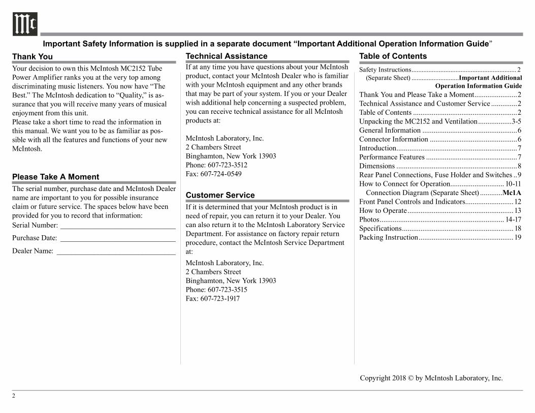
MC2152
Tube Power Amplifier
Owner’s Manual
2
Your decision to own this McIntosh MC2152 Tube Power Amplifier ranks you at the very top among discriminating music listeners. You now have “The Best.” The McIntosh dedication to “Quality,” is as-surance that you will receive many years of musical enjoyment from this unit.Please take a short time to read the information in this manual. We want you to be as familiar as pos-sible with all the features and functions of your new McIntosh.
Copyright 2018 © by McIntosh Laboratory, Inc.
Table of ContentsThank You
Please Take A Moment
Technical AssistanceIf at any time you have questions about your McIntosh product, contact your McIntosh Dealer who is familiar with your McIntosh equipment and any other brands that may be part of your system. If you or your Dealer wish additional help concerning a suspected problem, you can receive technical assistance for all McIntosh products at:
McIntosh Laboratory, Inc.2 Chambers StreetBinghamton, New York 13903Phone: 607-723-3512Fax: 607-724-0549
Customer ServiceIf it is determined that your McIntosh product is in need of repair, you can return it to your Dealer. You can also return it to the McIntosh Laboratory Service Department. For assistance on factory repair return procedure, contact the McIntosh Service Department at:McIntosh Laboratory, Inc.2 Chambers StreetBinghamton, New York 13903Phone: 607-723-3515Fax: 607-723-1917
The serial number, purchase date and McIntosh Dealer name are important to you for possible insurance claim or future service. The spaces below have been provided for you to record that information:Serial Number: _______________________________
Purchase Date: _______________________________
Dealer Name: ________________________________
Important Safety Information is supplied in a separate document “Important Additional Operation Information Guide”
Safety Instructions .............................................................. 2 (Separate Sheet) ............................Important Additional Operation Information GuideThank You and Please Take a Moment .......................2Technical Assistance and Customer Service ..............2Table of Contents ........................................................2Unpacking the MC2152 and Ventilation ..................3-5General Information ...................................................6Connector Information ...............................................6Introduction .................................................................7Performance Features .................................................7Dimensions .................................................................8Rear Panel Connections, Fuse Holder and Switches ..9How to Connect for Operation ............................. 10-11 Connection Diagram (Separate Sheet) ............Mc1AFront Panel Controls and Indicators..........................12How to Operate .........................................................13Photos ................................................................... 14-17Specifications ............................................................ 18Packing Instruction ................................................... 19
3
IMPORTANT!INSTRUCTIONS FOR REMOVAL
OF FOAM INSERT OVER THEVACUUM TUBES PRIOR TO
CONNECTING THE A.C. POWERSUPPLY CORD, START ON THE
NEXT PAGE.
4
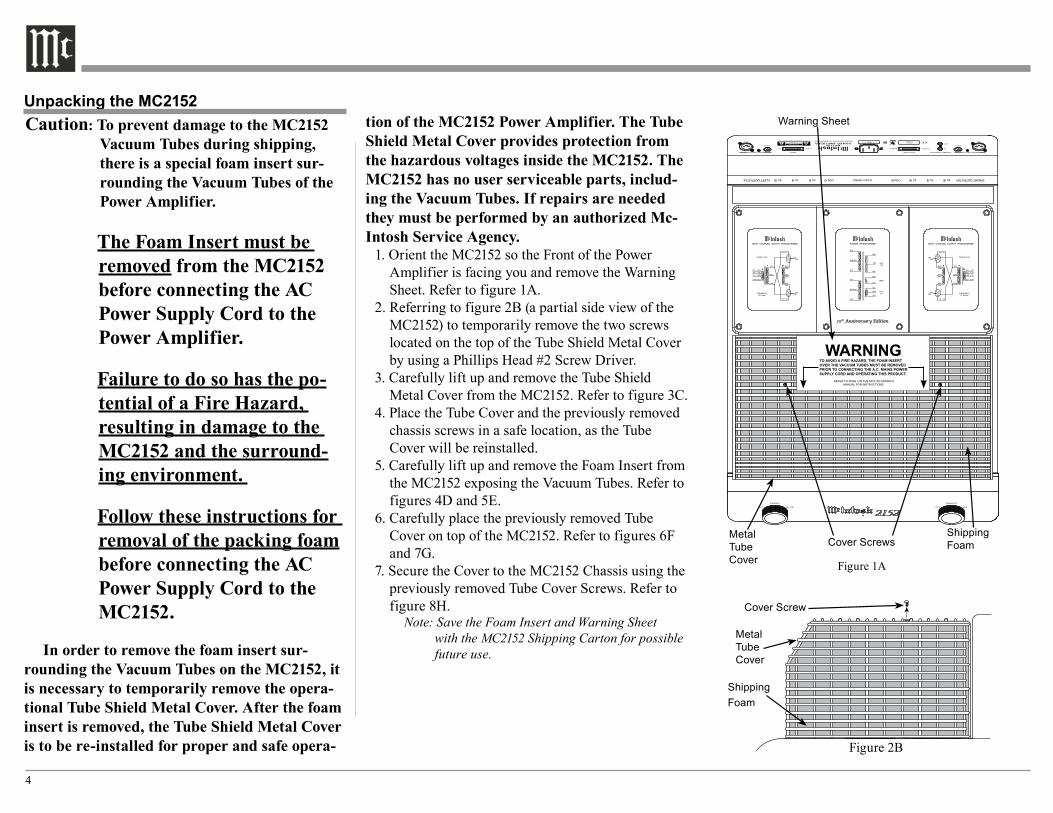
Unpacking the MC2152Caution: To prevent damage to the MC2152
Vacuum Tubes during shipping, there is a special foam insert sur-rounding the Vacuum Tubes of the Power Amplifier.
The Foam Insert must be removed from the MC2152 before connecting the AC Power Supply Cord to the Power Amplifier.
Failure to do so has the po-tential of a Fire Hazard, resulting in damage to the MC2152 and the surround-ing environment.
Follow these instructions for removal of the packing foam before connecting the AC Power Supply Cord to the MC2152.
In order to remove the foam insert sur-rounding the Vacuum Tubes on the MC2152, it is necessary to temporarily remove the opera-tional Tube Shield Metal Cover. After the foam insert is removed, the Tube Shield Metal Cover is to be re-installed for proper and safe opera-
tion of the MC2152 Power Amplifier. The Tube Shield Metal Cover provides protection from the hazardous voltages inside the MC2152. The MC2152 has no user serviceable parts, includ-ing the Vacuum Tubes. If repairs are needed they must be performed by an authorized Mc-Intosh Service Agency.
1. Orient the MC2152 so the Front of the Power Amplifier is facing you and remove the Warning Sheet. Refer to figure 1A.
2. Referring to figure 2B (a partial side view of the MC2152) to temporarily remove the two screws located on the top of the Tube Shield Metal Cover by using a Phillips Head #2 Screw Driver.
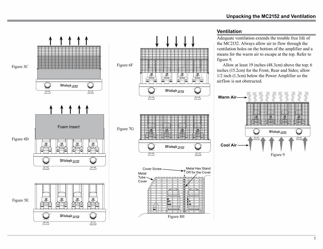
3. Carefully lift up and remove the Tube Shield Metal Cover from the MC2152. Refer to figure 3C.
4. Place the Tube Cover and the previously removed chassis screws in a safe location, as the Tube Cover will be reinstalled.
5. Carefully lift up and remove the Foam Insert from the MC2152 exposing the Vacuum Tubes. Refer to figures 4D and 5E.
6. Carefully place the previously removed Tube Cover on top of the MC2152. Refer to figures 6F and 7G.
7. Secure the Cover to the MC2152 Chassis using the previously removed Tube Cover Screws. Refer to figure 8H.
Note: Save the Foam Insert and Warning Sheet with the MC2152 Shipping Carton for possible future use.
Figure 1A
MetalTubeCover
Cover ScrewsShippingFoam
Warning Sheet
TO AVOID A FIRE HAZARD, THE FOAM INSERT OVER THE VACUUM TUBES MUST BE REMOVED PRIOR TO CONNECTING THE A.C. MAINS POWER SUPPLY CORD AND OPERATING THIS PRODUCT.
WARNINGREFER TO PAGE 3 IN THE MC2152 OWNER’S
MANUAL FOR INSTRUCTIONS.
Figure 2B
MetalTubeCover
Cover Screw
ShippingFoam
5
Adequate ventilation extends the trouble free life of the MC2152. Always allow air to flow through the ventilation holes on the bottom of the amplifier and a means for the warm air to escape at the top. Refer to figure 9.
Allow at least 19 inches (48.3cm) above the top; 6 inches (15.2cm) for the Front, Rear and Sides; allow 1/2 inch (1.3cm) below the Power Amplifier so the airflow is not obstructed.
Ventilation
Warm Air
Cool Air
Figure 9
Unpacking the MC2152 and Ventilation
Figure 5E
Figure 6F
Figure 7G
Figure 8H
Figure 4D
Figure 3C
Cover ScrewMetalTubeCover
Metal Hex Stand Off for the Cover
Foam Insert
6
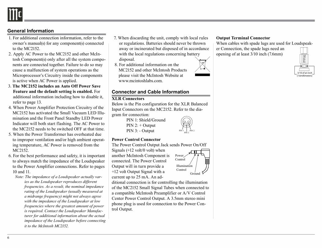
Output Terminal ConnectorWhen cables with spade lugs are used for Loudspeak-er Connection, the spade lugs need an opening of at least 3/10 inch (7.6mm)
XLR ConnectorsBelow is the Pin configuration for the XLR Balanced Input Connectors on the MC2152. Refer to the dia-gram for connection: PIN 1: Shield/Ground PIN 2: + Output PIN 3: - Output
Power Control ConnectorThe Power Control Output Jack sends Power On/Off Signals (+12 volt/0 volt) when another McIntosh Component is connected. The Power Control Output will in turn provide a +12 volt Output Signal with a current up to 25 mA. An ad-ditional connection is for controlling the illumination of the MC2152 Small Signal Tubes when connected to a compatible McIntosh Preamplifier or A/V Control Center Power Control Output. A 3.5mm stereo mini phone plug is used for connection to the Power Con-trol Output.
PowerControl
IlluminationControl
Ground
1. For additional connection information, refer to the owner’s manual(s) for any component(s) connected to the MC2152.
2. Apply AC Power to the MC2152 and other McIn-tosh Component(s) only after all the system compo-nents are connected together. Failure to do so may cause a malfunction of system operations as the Microprocessor’s Circuitry inside the components is active when AC Power is applied.
3. The MC2152 includes an Auto Off Power Save Feature and the default setting is enabled. For additional information including how to disable it, refer to page 13.
4. When Power Amplifier Protection Circuitry of the MC2152 has activated the Small Vacuum LED Illu-mination and the Front Panel Standby LED Power Indicator will both start flashing. The AC Power to the MC2152 needs to be switched OFF at that time.
5. When the Power Transformer has overheated due to improper ventilation and/or high ambient operat-ing temperature, AC Power is removed from the MC2152.
6. For the best performance and safety, it is important to always match the impedance of the Loudspeaker to the Power Amplifier connections. Refer to pages 10 and 11.
Note: The impedance of a Loudspeaker actually var-ies as the Loudspeaker reproduces different frequencies. As a result, the nominal impedance rating of the Loudspeaker (usually measured at a midrange frequency) might not always agree with the impedance of the Loudspeaker at low frequencies where the greatest amount of power is required. Contact the Loudspeaker Manufac-turer for additional information about the actual impedance of the Loudspeaker before connecting it to the McIntosh MC2152.
7. When discarding the unit, comply with local rules or regulations. Batteries should never be thrown away or incinerated but disposed of in accordance with the local regulations concerning battery disposal.
8. For additional information on the MC2152 and other McIntosh Products please visit the McIntosh Website at www.mcintoshlabs.com.
Connector and Cable Information
General Information
PIN 1 PIN 2PIN 3
3/10 of an inch(7.6millimeters)
7
General Information, Cable Information, Introduction and Performance Features
IntroductionNow you can take advantage of traditional McIntosh standards of excellence in the MC2152 Tube Power Amplifier. The 150 watt power output per channel will drive any high quality Loudspeaker System. The MC2152 reproduction is sonically transparent and ab-solutely accurate. The McIntosh Sound is “The Sound of the Music Itself.”
Performance Features• Power OutputThe MC2152 is a Tube Power Amplifier with a ca-pability of 150 watts per channel into 2, 4 or 8 ohm Loudspeakers with less than 0.5% distortion.
• Unity Coupled CircuitryThe MC2152 Power Amplifier uses the famous McIn-tosh Patented Unity Coupled Circuit which provides low distortion, extended frequency response and cool operating output tubes.
• Multifilar Wound Output TransformerThe MC2152 Output Transformer Windings are part of the Unity Coupled Circuitry. There are two bifilar wound primaries, one for the cathodes and one for the plates. The secondary winding is wound together with the primary windings. This provides very close primary to secondary coupling. The result is flat fre-quency response and wide power bandwidth.
• Balanced and Unbalanced InputBalanced connections guard against induced noise and allow long cable runs without compromising sound quality.
• Sentry Monitor Tube ProtectionMcIntosh Sentry Monitor Tube Protection Circuits ensure the MC2152 will have a long and trouble free operating life.
• Vacuum Tube SocketsSmall Signal Vacuum Tubes Sockets have Ceramic Base construction with gold plated contacts, providing protection from atmospheric contamination. Output Tube Sockets include Air-Pipe cooling at their bases for long term operation.
• Amplifier Gold Plated ConnectorsGold Plated Input Jacks and Output Binding Posts provide trouble free connections.
• Special Power SupplyA regulated Power Supply, a very large core Power Transformer and large capacitors ensure stable noise free operation even though the power line varies.
• LED Tube IlluminationTri-Color LEDs illuminate the small signal process-ing tubes of the MC2152. They indicate tube warm up, normal and sentry monitor modes of operation.
• Special ChassisThe Aluminum Extrusion Heavy Duty Chassis is a Highly Rugged Construction for the very large size of the MC2152 McIntosh Tube Power Amplifier. This type of design will retain the pristine beauty of the MC2152 for many years to come.
8
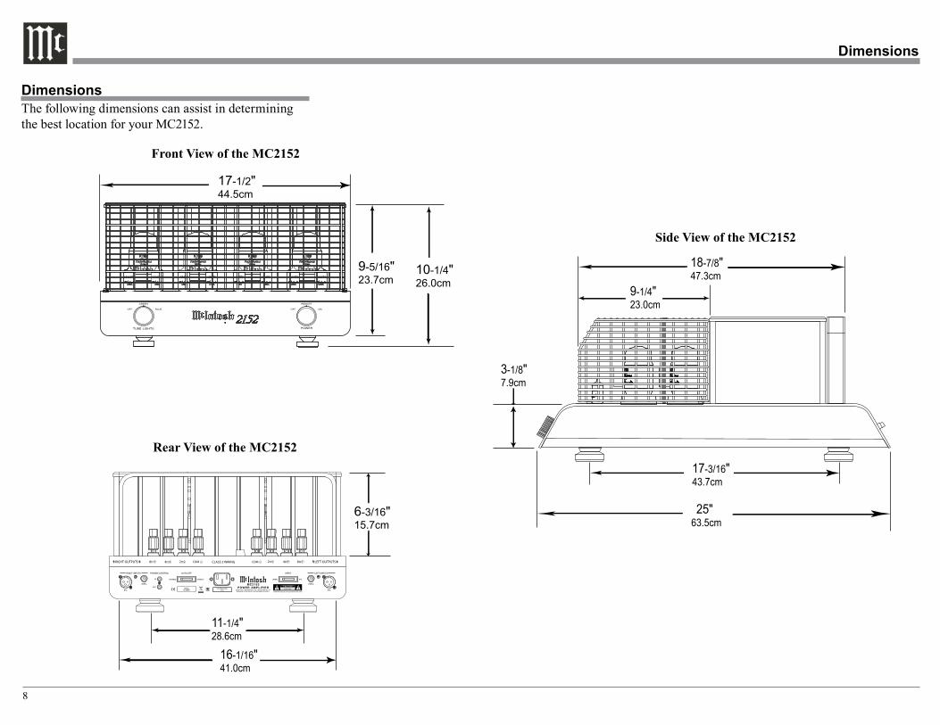
DimensionsThe following dimensions can assist in determining the best location for your MC2152.
Dimensions
RIGHT OUTPUTS 8Ω + 4Ω + 2Ω+ COM - LEFT OUTPUTSCOM - 2Ω+ 4Ω + 8Ω +CLASS 2 WIRING
Front View of the MC2152
Rear View of the MC2152
Side View of the MC2152
17-1/2" 44.5cm
10-1/4" 26.0cm
9-5/16" 23.7cm
11-1/4" 28.6cm
6-3/16" 15.7cm
17-3/16" 43.7cm
25" 63.5cm
3-1/8" 7.9cm
18-7/8" 47.3cm
9-1/4" 23.0cm
16-1/16" 41.0cm
9
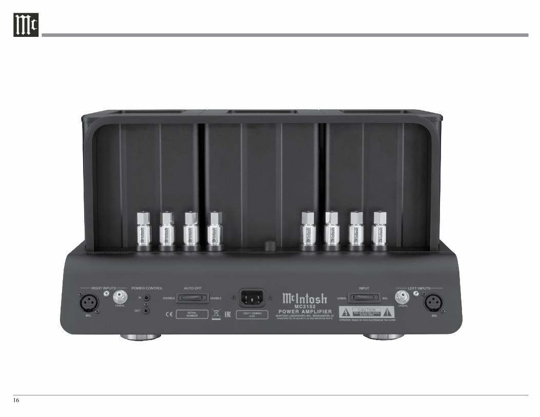
RIGHT OUTPUTS 8Ω + 4Ω + 2Ω+ COM - LEFT OUTPUTSCOM - 2Ω+ 4Ω + 8Ω +CLASS 2 WIRING
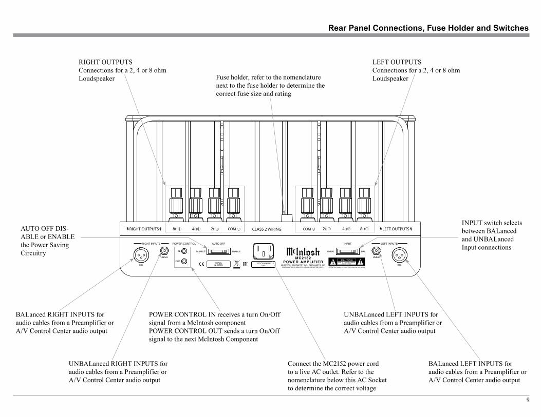
Rear Panel Connections, Fuse Holder and Switches
Connect the MC2152 power cord to a live AC outlet. Refer to the nomenclature below this AC Socket to determine the correct voltage
POWER CONTROL IN receives a turn On/Off signal from a McIntosh componentPOWER CONTROL OUT sends a turn On/Off signal to the next McIntosh Component
BALanced RIGHT INPUTS for audio cables from a Preamplifier or A/V Control Center audio output
LEFT OUTPUTSConnections for a 2, 4 or 8 ohm LoudspeakerFuse holder, refer to the nomenclature
next to the fuse holder to determine the correct fuse size and rating
AUTO OFF DIS-ABLE or ENABLE the Power Saving Circuitry
RIGHT OUTPUTSConnections for a 2, 4 or 8 ohm Loudspeaker
INPUT switch selects between BALanced and UNBALanced Input connections
UNBALanced RIGHT INPUTS for audio cables from a Preamplifier or A/V Control Center audio output
BALanced LEFT INPUTS for audio cables from a Preamplifier or A/V Control Center audio output
UNBALanced LEFT INPUTS for audio cables from a Preamplifier or A/V Control Center audio output
10
Caution: Do not connect the AC Power Cord to the MC2152 Rear Panel until after the Loudspeaker Connections are made. Failure to observe this could result in Electric Shock.
The connection instructions below, together with the MC2152 Connection Diagram located on the separate folded sheet “Mc1A”, is an example of a typical audio system. Your system may vary from this, however the actual components would be connected in a similar manner. For additional information refer to “Connec-tor and Cable Information” on page 6.
1. For Remote Power Control, connect a power control cable from the Audio Preamplifier Power Control Main Output Jack to the Power Amplifier POWER CONTROL IN Jack.
2. Connect XLR cables from the Balanced Main Output connector of the Audio Preamplifier to the Power Amplifier BALanced INPUTS. Place the INPUT Switch in the BALanced Position.
Note: An optional hookup is to use unbalanced cable and place the INPUT MODE Switch in the UNBALanced Position.
This McIntosh MC2152 Power Amplifier is designed for Loudspeakers with an impedance of 2 ohms, 4 ohms or 8 ohms. Connect a single Loudspeaker only to the Output Terminals.
When connecting Loudspeakers to the MC2152 it is very important to use cables of adequate size, so there is little to no power loss in the cables. The size is specified in Gauge Numbers or AWG (American Wire Gauge). The smaller the Gauge number, the larger the wire size:
Loudspeaker Cable Distance vs Wire Gauge Guide
LoudspeakerImpedance
25 feet(7.62 meters)
or less
50 feet(15.24 meters)
or less
100 feet(30.48 meters)
or less
2 Ohms 12AWG 10AWG 8AWG4 Ohms 14AWG 12AWG 10AWG8 Ohms 16AWG 14AWG 12AWG
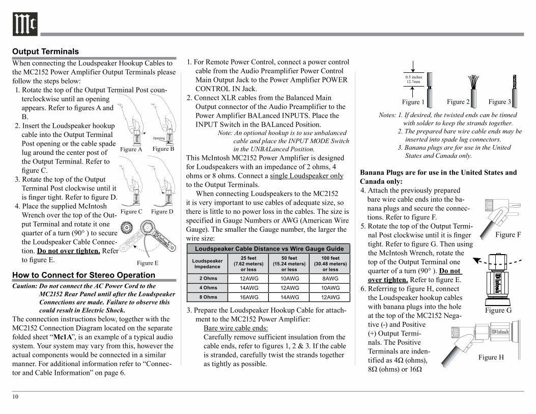
3. Prepare the Loudspeaker Hookup Cable for attach-ment to the MC2152 Power Amplifier:
Bare wire cable ends:Carefully remove sufficient insulation from the cable ends, refer to figures 1, 2 & 3. If the cable is stranded, carefully twist the strands together as tightly as possible.
Notes: 1. If desired, the twisted ends can be tinned with solder to keep the strands together.
2. The prepared bare wire cable ends may be inserted into spade lug connectors.
3. Banana plugs are for use in the United States and Canada only.
Banana Plugs are for use in the United States and Canada only:4. Attach the previously prepared
bare wire cable ends into the ba-nana plugs and secure the connec-tions. Refer to figure F.
5. Rotate the top of the Output Termi-nal Post clockwise until it is finger tight. Refer to figure G. Then using the McIntosh Wrench, rotate the top of the Output Terminal one quarter of a turn (90° ). Do not over tighten. Refer to figure E.
6. Referring to figure H, connect the Loudspeaker hookup cables with banana plugs into the hole at the top of the MC2152 Nega-tive (-) and Positive (+) Output Termi-nals. The Positive Terminals are inden-tified as 4Ω (ohms), 8Ω (ohms) or 16Ω
Figure 1 Figure 2 Figure 3
How to Connect for Stereo Operation
Output TerminalsWhen connecting the Loudspeaker Hookup Cables to the MC2152 Power Amplifier Output Terminals please follow the steps below:1. Rotate the top of the Output Terminal Post coun-
terclockwise until an opening appears. Refer to figures A and B.
2. Insert the Loudspeaker hookup cable into the Output Terminal Post opening or the cable spade lug around the center post of the Output Terminal. Refer to figure C.
3. Rotate the top of the Output Terminal Post clockwise until it is finger tight. Refer to figure D.
4. Place the supplied McIntosh Wrench over the top of the Out-put Terminal and rotate it one quarter of a turn (90° ) to secure the Loudspeaker Cable Connec-tion. Do not over tighten. Refer to figure E.
Figure A
Opening
Figure B
Figure C Figure D
Figure E
Figure F Figure H
Figure F Figure H
Figure G
11
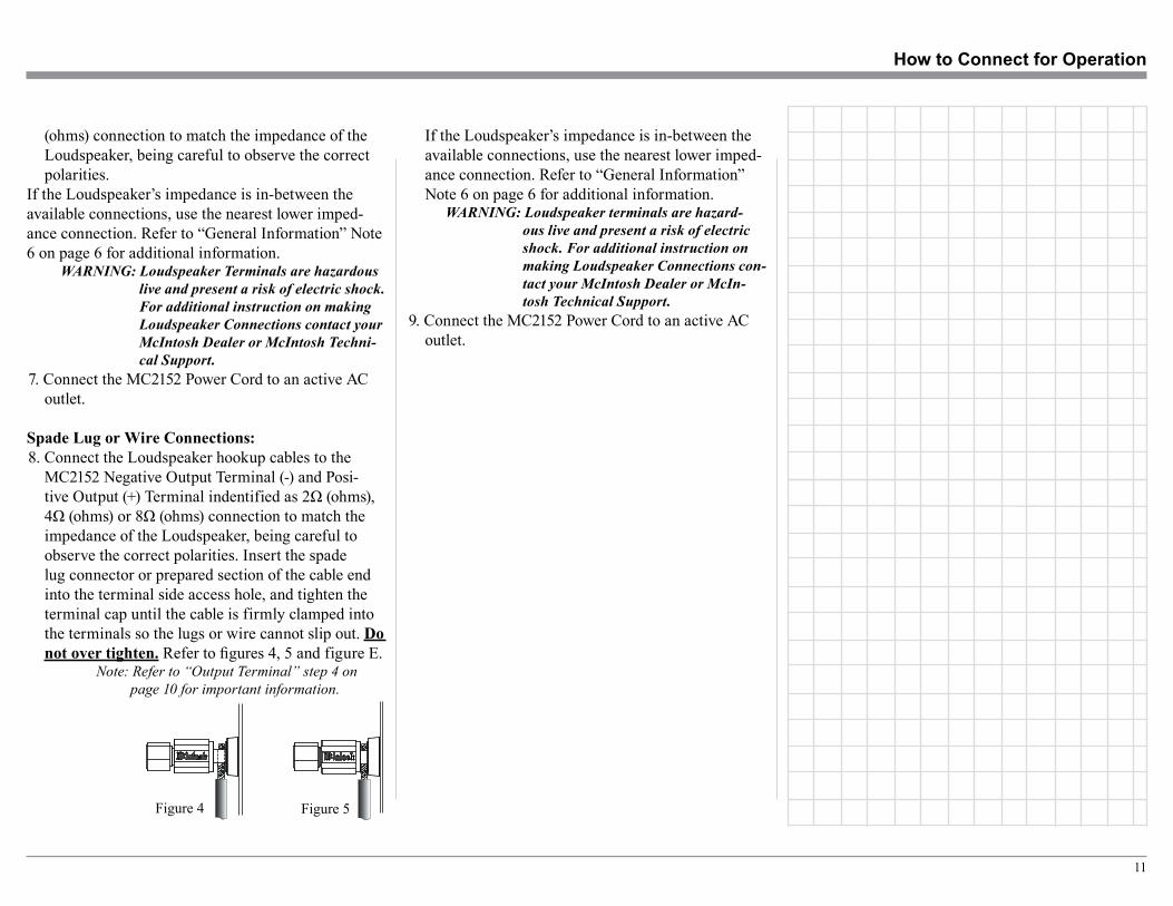
If the Loudspeaker’s impedance is in-between the available connections, use the nearest lower imped-ance connection. Refer to “General Information” Note 6 on page 6 for additional information.
WARNING: Loudspeaker terminals are hazard-ous live and present a risk of electric shock. For additional instruction on making Loudspeaker Connections con-tact your McIntosh Dealer or McIn-tosh Technical Support.
9. Connect the MC2152 Power Cord to an active AC outlet.
(ohms) connection to match the impedance of the Loudspeaker, being careful to observe the correct polarities.
If the Loudspeaker’s impedance is in-between the available connections, use the nearest lower imped-ance connection. Refer to “General Information” Note 6 on page 6 for additional information.
WARNING: Loudspeaker Terminals are hazardous live and present a risk of electric shock. For additional instruction on making Loudspeaker Connections contact your McIntosh Dealer or McIntosh Techni-cal Support.
7. Connect the MC2152 Power Cord to an active AC outlet.
Spade Lug or Wire Connections:8. Connect the Loudspeaker hookup cables to the
MC2152 Negative Output Terminal (-) and Posi-tive Output (+) Terminal indentified as 2Ω (ohms), 4Ω (ohms) or 8Ω (ohms) connection to match the impedance of the Loudspeaker, being careful to observe the correct polarities. Insert the spade lug connector or prepared section of the cable end into the terminal side access hole, and tighten the terminal cap until the cable is firmly clamped into the terminals so the lugs or wire cannot slip out. Do not over tighten. Refer to figures 4, 5 and figure E.
Note: Refer to “Output Terminal” step 4 on page 10 for important information.
How to Connect for Operation
Figure 4 Figure 5
12
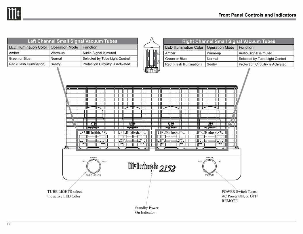
Standby Power On Indicator
POWER Switch Turns AC Power ON, or OFF/REMOTE
Front Panel Controls and Indicators
TUBE LIGHTS select the active LED Color
Left Channel Small Signal Vacuum TubesLED Illumination Color Operation Mode FunctionAmber Warm-up Audio Signal is mutedGreen or Blue Normal Selected by Tube Light ControlRed (Flash Illumination) Sentry Protection Circuitry is Activated
Right Channel Small Signal Vacuum TubesLED Illumination Color Operation Mode FunctionAmber Warm-up Audio Signal is mutedGreen or Blue Normal Selected by Tube Light ControlRed (Flash Illumination) Sentry Protection Circuitry is Activated
13
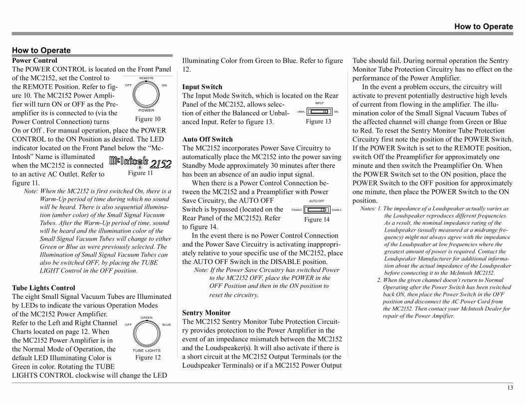
Illuminating Color from Green to Blue. Refer to figure 12.
Input SwitchThe Input Mode Switch, which is located on the Rear Panel of the MC2152, allows selec-tion of either the Balanced or Unbal-anced Input. Refer to figure 13.
Auto Off SwitchThe MC2152 incorporates Power Save Circuitry to automatically place the MC2152 into the power saving Standby Mode approximately 30 minutes after there has been an absence of an audio input signal.
When there is a Power Control Connection be-tween the MC2152 and a Preamplifier with Power Save Circuitry, the AUTO OFF Switch is bypassed (located on the Rear Panel of the MC2152). Refer to figure 14.
In the event there is no Power Control Connection and the Power Save Circuitry is activating inappropri-ately relative to your specific use of the MC2152, place the AUTO OFF Switch in the DISABLE position.
Note: If the Power Save Circuitry has switched Power to the MC2152 OFF, place the POWER in the OFF Position and then in the ON position to reset the circuitry.
Sentry MonitorThe MC2152 Sentry Monitor Tube Protection Circuit-ry provides protection to the Power Amplifier in the event of an impedance mismatch between the MC2152 and the Loudspeaker(s). It will also activate if there is a short circuit at the MC2152 Output Terminals (or the Loudspeaker Terminals) or if a MC2152 Power Output
How to Operate
How to Operate
Power ControlThe POWER CONTROL is located on the Front Panel of the MC2152, set the Control to the REMOTE Position. Refer to fig-ure 10. The MC2152 Power Ampli-fier will turn ON or OFF as the Pre-amplifier its is connected to (via the Power Control Connection) turns On or Off . For manual operation, place the POWER CONTROL to the ON Position as desired. The LED indicator located on the Front Panel below the “Mc-Intosh” Name is illuminated when the MC2152 is connected to an active AC Outlet. Refer to figure 11.
Note: When the MC2152 is first switched On, there is a Warm-Up period of time during which no sound will be heard. There is also sequential illumina-tion (amber color) of the Small Signal Vacuum Tubes. After the Warm-Up period of time, sound will be heard and the illumination color of the Small Signal Vacuum Tubes will change to either Green or Blue as were previously selected. The Illumination of Small Signal Vacuum Tubes can also be switched OFF, by placing the TUBE LIGHT Control in the OFF position.
Tube Lights ControlThe eight Small Signal Vacuum Tubes are Illuminated by LEDs to indicate the various Operation Modes of the MC2152 Power Amplifier. Refer to the Left and Right Channel Charts located on page 12. When the MC2152 Power Amplifier is in the Normal Mode of Operation, the default LED Illuminating Color is Green in color. Rotating the TUBE LIGHTS CONTROL clockwise will change the LED
Notes: 1. The impedance of a Loudspeaker actually varies as the Loudspeaker reproduces different frequencies. As a result, the nominal impedance rating of the Loudspeaker (usually measured at a midrange fre-quency) might not always agree with the impedance of the Loudspeaker at low frequencies where the greatest amount of power is required. Contact the Loudspeaker Manufacturer for additional informa-tion about the actual impedance of the Loudspeaker before connecting it to the McIntosh MC2152.
2. When the given channel doesn’t return to Normal Operating after the Power Switch has been switched back ON, then place the Power Switch in the OFF position and disconnect the AC Power Cord from the MC2152. Then contact your McIntosh Dealer for repair of the Power Ampifier.
Figure 10
Figure 11
Figure 12
Figure 13
RIGHT OUTPUTS 8Ω + 4Ω + 2Ω+ COM - LEFT OUTPUTSCOM - 2Ω+ 4Ω + 8Ω +CLASS 2 WIRING
RIGHT OUTPUTS 8Ω + 4Ω + 2Ω+ COM - LEFT OUTPUTSCOM - 2Ω+ 4Ω + 8Ω +CLASS 2 WIRING
Figure 14
Tube should fail. During normal operation the Sentry Monitor Tube Protection Circuitry has no effect on the performance of the Power Amplifier.
In the event a problem occurs, the circuitry will activate to prevent potentially destructive high levels of current from flowing in the amplifier. The illu-mination color of the Small Signal Vacuum Tubes of the affected channel will change from Green or Blue to Red. To reset the Sentry Monitor Tube Protection Circuitry first note the position of the POWER Switch. If the POWER Switch is set to the REMOTE position, switch Off the Preamplifier for approximately one minute and then switch the Preamplifier On. When the POWER Switch set to the ON position, place the POWER Switch to the OFF position for approximately one minute, then place the POWER Switch to the ON position.
14
15
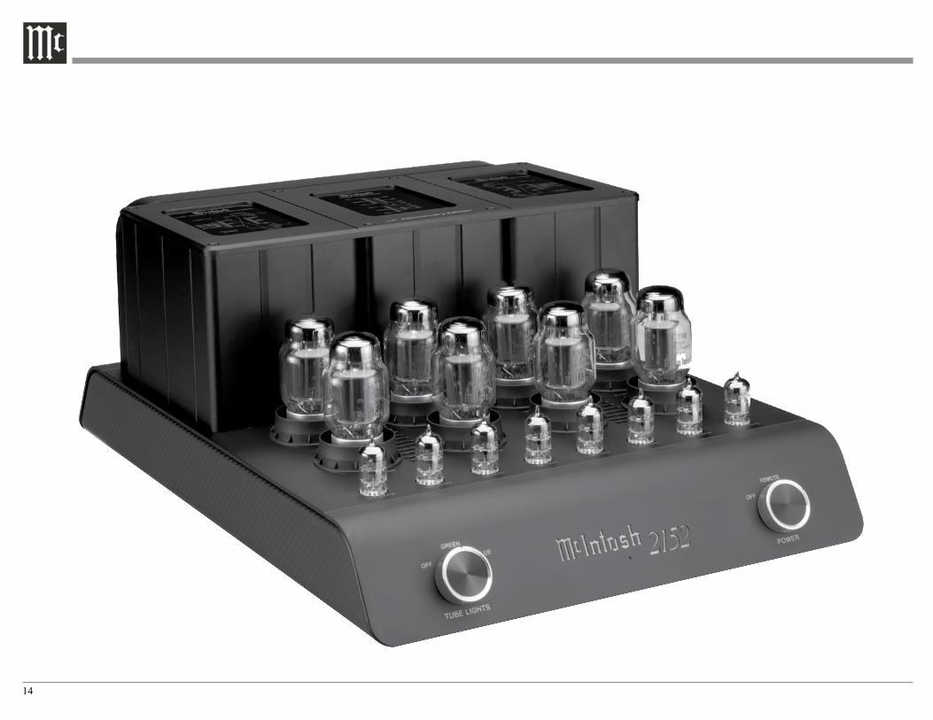
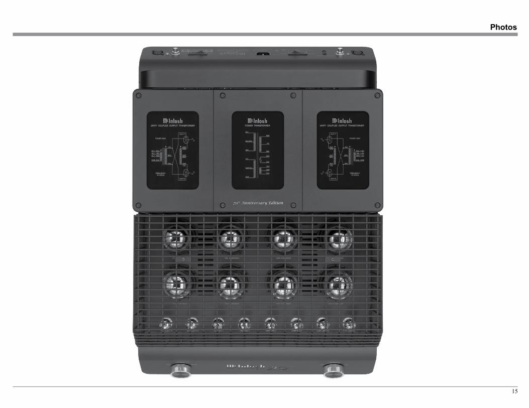
Photos
16
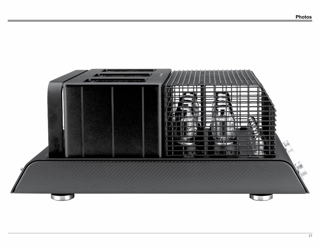
17
Photos
18
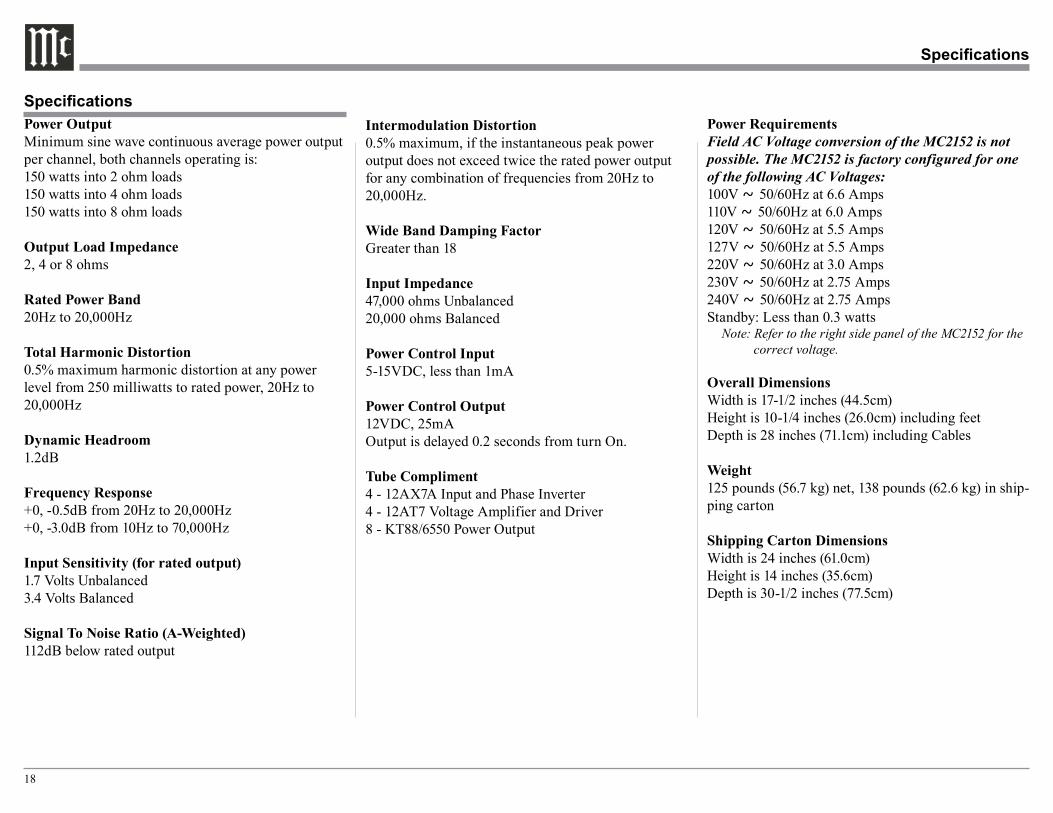
Power RequirementsField AC Voltage conversion of the MC2152 is not possible. The MC2152 is factory configured for one of the following AC Voltages:100V ~ 50/60Hz at 6.6 Amps110V ~ 50/60Hz at 6.0 Amps120V ~ 50/60Hz at 5.5 Amps127V ~ 50/60Hz at 5.5 Amps220V ~ 50/60Hz at 3.0 Amps230V ~ 50/60Hz at 2.75 Amps240V ~ 50/60Hz at 2.75 AmpsStandby: Less than 0.3 watts
Note: Refer to the right side panel of the MC2152 for the correct voltage.
Overall DimensionsWidth is 17-1/2 inches (44.5cm)Height is 10-1/4 inches (26.0cm) including feetDepth is 28 inches (71.1cm) including Cables
Weight125 pounds (56.7 kg) net, 138 pounds (62.6 kg) in ship-ping carton
Shipping Carton DimensionsWidth is 24 inches (61.0cm)Height is 14 inches (35.6cm)Depth is 30-1/2 inches (77.5cm)
Power OutputMinimum sine wave continuous average power output per channel, both channels operating is:150 watts into 2 ohm loads150 watts into 4 ohm loads150 watts into 8 ohm loads
Output Load Impedance2, 4 or 8 ohms
Rated Power Band20Hz to 20,000Hz
Total Harmonic Distortion0.5% maximum harmonic distortion at any power level from 250 milliwatts to rated power, 20Hz to 20,000Hz
Dynamic Headroom1.2dB
Frequency Response+0, -0.5dB from 20Hz to 20,000Hz+0, -3.0dB from 10Hz to 70,000Hz
Input Sensitivity (for rated output)1.7 Volts Unbalanced3.4 Volts Balanced
Signal To Noise Ratio (A-Weighted)112dB below rated output
Intermodulation Distortion0.5% maximum, if the instantaneous peak power output does not exceed twice the rated power output for any combination of frequencies from 20Hz to 20,000Hz.
Wide Band Damping FactorGreater than 18
Input Impedance47,000 ohms Unbalanced20,000 ohms Balanced
Power Control Input5-15VDC, less than 1mA
Power Control Output12VDC, 25mAOutput is delayed 0.2 seconds from turn On.
Tube Compliment4 - 12AX7A Input and Phase Inverter4 - 12AT7 Voltage Amplifier and Driver8 - KT88/6550 Power Output
Specifications
Specifications
19
Packing Instructions
Packing Instructions
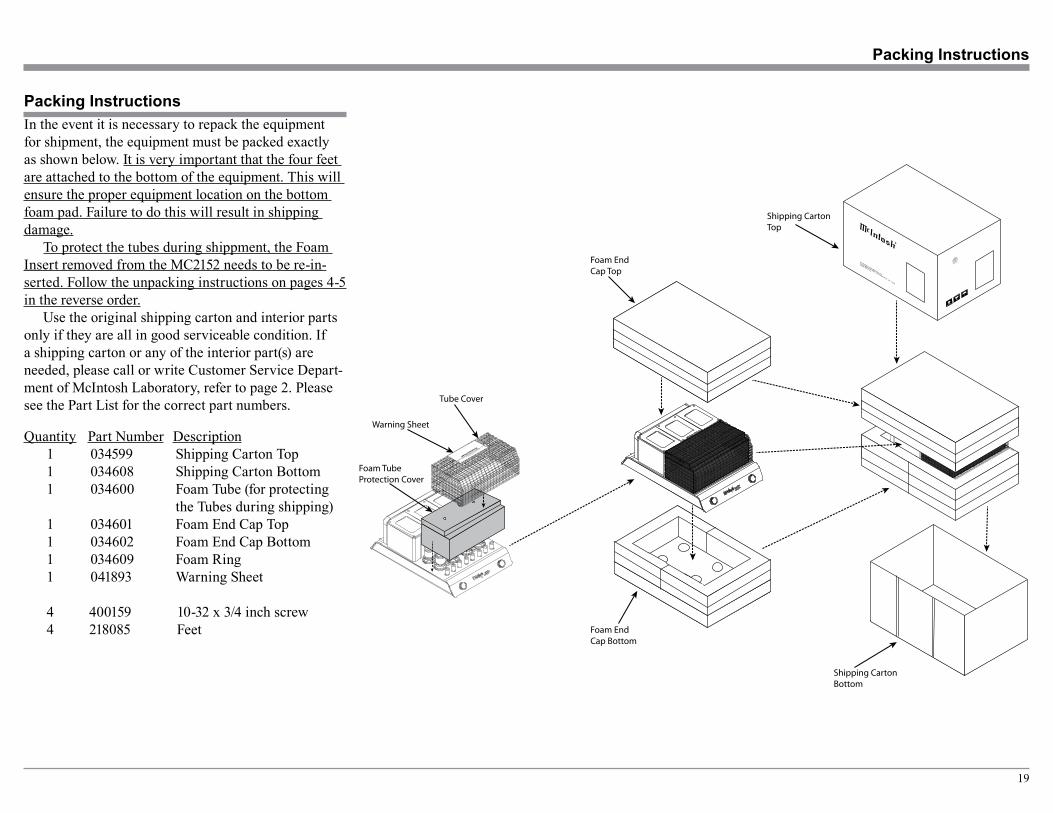
Quantity Part Number Description1 034599 Shipping Carton Top1 034608 Shipping Carton Bottom1 034600 Foam Tube (for protecting the Tubes during shipping)1 034601 Foam End Cap Top1 034602 Foam End Cap Bottom1 034609 Foam Ring1 041893 Warning Sheet
4 400159 10-32 x 3/4 inch screw4 218085 Feet
In the event it is necessary to repack the equipment for shipment, the equipment must be packed exactly as shown below. It is very important that the four feet are attached to the bottom of the equipment. This will ensure the proper equipment location on the bottom foam pad. Failure to do this will result in shipping damage.
To protect the tubes during shippment, the Foam Insert removed from the MC2152 needs to be re-in-serted. Follow the unpacking instructions on pages 4-5 in the reverse order.
Use the original shipping carton and interior parts only if they are all in good serviceable condition. If a shipping carton or any of the interior part(s) are needed, please call or write Customer Service Depart-ment of McIntosh Laboratory, refer to page 2. Please see the Part List for the correct part numbers. Tube Cover
Foam TubeProtection Cover
Foam EndCap Top
Foam EndCap Bottom
Shipping CartonTop
Shipping CartonBottom
Warning Sheet

The continuous improvement of its products is the policy of McIntosh Laboratory Incorporated who reserve the right to improve design without notice.Printed in the U.S.A.
McIntosh Laboratory, Inc.2 Chambers Street
Binghamton, NY 13903www.mcintoshlabs.com
McIntosh Part No. 04188800