Embed Size (px)
Citation preview

McAfee SMCReference Guide 5.7
Secur i ty Management Center

Legal InformationThe use of the products described in these materials is subject to the then current end-user license agreement, which can be found at the McAfee website:http://www.mcafee.com/us/about/legal/license-agreements.aspx
Revision: SGMRG_20140327
2

TABLE OF CONTENTS
INTRODUCTION
CHAPTER 1Using SMC Documentation. . . . . . . . . . . . . . . . 9
How to Use This Guide . . . . . . . . . . . . . . . . . . 10Typographical Conventions . . . . . . . . . . . . . . 10
Documentation Available . . . . . . . . . . . . . . . . . 11Product Documentation. . . . . . . . . . . . . . . . . 11Support Documentation . . . . . . . . . . . . . . . . 12System Requirements. . . . . . . . . . . . . . . . . . 12Supported Features . . . . . . . . . . . . . . . . . . . 12
Contact Information . . . . . . . . . . . . . . . . . . . . 12
CHAPTER 2Introduction to the Security Management Center . . . . . . . . . . . . . . . . . . . . . . . . . . . . . . . 13
McAfee NGFW Solution . . . . . . . . . . . . . . . . . . 14SMC Components. . . . . . . . . . . . . . . . . . . . . . 15
Management Clients. . . . . . . . . . . . . . . . . . . 16Management Server . . . . . . . . . . . . . . . . . . . 16Log Server . . . . . . . . . . . . . . . . . . . . . . . . . . 17Web Portal Server. . . . . . . . . . . . . . . . . . . . . 17Authentication Server . . . . . . . . . . . . . . . . . . 17
Main Benefits of the Security Management Center . . . . . . . . . . . . . . . . . . . . . . . . . . . . . . 18
Centralized Remote Management . . . . . . . . . 18Support for Large-Scale Installations . . . . . . . 18High Availability . . . . . . . . . . . . . . . . . . . . . . 18
Managing Licenses. . . . . . . . . . . . . . . . . . . . . 19
CHAPTER 3Security Management Center Deployment . . . . . 21
Overview of Security Management Center Deployment . . . . . . . . . . . . . . . . . . . . . . . . . . 22
Supported Platforms. . . . . . . . . . . . . . . . . . . 22General Deployment Guidelines . . . . . . . . . . . 22
Security Considerations . . . . . . . . . . . . . . . . . 23Positioning the Management Server . . . . . . . . . 23Positioning Log Servers. . . . . . . . . . . . . . . . . . 24Positioning Management Clients . . . . . . . . . . . 24Example Deployment Scenario. . . . . . . . . . . . . 25
CONFIGURATION TOOLS
CHAPTER 4Management Client Basics . . . . . . . . . . . . . . . . 29
Introduction . . . . . . . . . . . . . . . . . . . . . . . . . . 30System Monitoring Tools. . . . . . . . . . . . . . . . . 30
The Domain Overview. . . . . . . . . . . . . . . . . . 30The System Status View. . . . . . . . . . . . . . . . 30The Info Panel . . . . . . . . . . . . . . . . . . . . . . . 31Overviews . . . . . . . . . . . . . . . . . . . . . . . . . . 32The Logs View . . . . . . . . . . . . . . . . . . . . . . . 33Reports. . . . . . . . . . . . . . . . . . . . . . . . . . . . 35
Configuration Views . . . . . . . . . . . . . . . . . . . . 36The Policy Editing View . . . . . . . . . . . . . . . . . . 36
CHAPTER 5Introduction to Elements in the SMC . . . . . . . . 37
Introduction to Elements. . . . . . . . . . . . . . . . . 38Administration . . . . . . . . . . . . . . . . . . . . . . . . 38Security Engine Configuration . . . . . . . . . . . . . 40User Authentication Configuration . . . . . . . . . . 41Monitoring . . . . . . . . . . . . . . . . . . . . . . . . . . . 42Network Elements . . . . . . . . . . . . . . . . . . . . . 44Services . . . . . . . . . . . . . . . . . . . . . . . . . . . . 45Situations . . . . . . . . . . . . . . . . . . . . . . . . . . . 45VPN Configuration . . . . . . . . . . . . . . . . . . . . . 47
CHAPTER 6Expressions. . . . . . . . . . . . . . . . . . . . . . . . . . . 49
Introduction to Expressions. . . . . . . . . . . . . . . 50Operands . . . . . . . . . . . . . . . . . . . . . . . . . . . 50
Negation . . . . . . . . . . . . . . . . . . . . . . . . . . . 50Intersection . . . . . . . . . . . . . . . . . . . . . . . . . 51Union . . . . . . . . . . . . . . . . . . . . . . . . . . . . . 51
Expression Processing Order. . . . . . . . . . . . . . 52Grouping Operands Using Parentheses . . . . . . . . . . . . . . . . . . . . . . . . . 52Nesting Expressions. . . . . . . . . . . . . . . . . . . . 53
3Table of Contents

ADMINISTRATION TOOLS
CHAPTER 7Administrator Accounts . . . . . . . . . . . . . . . . . . 57
Overview of Administrator Accounts . . . . . . . . . 58Configuration of Administrator Accounts . . . . . . 58
Default Elements . . . . . . . . . . . . . . . . . . . . . 59Configuration Workflow . . . . . . . . . . . . . . . . . 60
Task 1: Create a New Administrator Role . . . . . . . . . . . . . . . . . . . . . . . . . . . . . 60Task 2: Create a New Access Control List . . . . . . . . . . . . . . . . . . . . . . . . . . . . . . 60Task 3: Create a New Administrator Element. . . . . . . . . . . . . . . . . . . . . . . . . . . 61
Using Administrator Accounts . . . . . . . . . . . . . 62Creating Web Portal User Accounts . . . . . . . . 62Using External Authentication for Administrators . . . . . . . . . . . . . . . . . . . . . . . 63Customizing Log Color Settings . . . . . . . . . . . 63Configuring the Administrator Password Policy. . . . . . . . . . . . . . . . . . . . . . . . . . . . . . 63
CHAPTER 8Domains . . . . . . . . . . . . . . . . . . . . . . . . . . . . . 65
Overview of Domains . . . . . . . . . . . . . . . . . . . 66Configuration of Domains . . . . . . . . . . . . . . . . 66
Default Elements . . . . . . . . . . . . . . . . . . . . . 66Configuration Workflow . . . . . . . . . . . . . . . . . 66
Task 1: Create Domains . . . . . . . . . . . . . . . 67Task 2: Associate Elements with Domains . . . . . . . . . . . . . . . . . . . . . . . . . . 67Task 3: Define the Administrator Permissions for the Domains . . . . . . . . . . . 68
Using Domains. . . . . . . . . . . . . . . . . . . . . . . . 68Default Categories for Domains . . . . . . . . . . . 68
Examples of Domains . . . . . . . . . . . . . . . . . . . 68Creating Separate Domains for Different Customers . . . . . . . . . . . . . . . . . . . . . . . . . . 68Creating Separate Domains for Different Sites . . . . . . . . . . . . . . . . . . . . . . . . . . . . . . 69
CHAPTER 9Categories . . . . . . . . . . . . . . . . . . . . . . . . . . . . 71
Overview of Categories . . . . . . . . . . . . . . . . . . 72Configuration of Categories . . . . . . . . . . . . . . . 72
Default Categories . . . . . . . . . . . . . . . . . . . . 72Configuration Workflow . . . . . . . . . . . . . . . . . 72
Task 1: Create Categories. . . . . . . . . . . . . . 72Task 2: Associate Elements with Categories . . . . . . . . . . . . . . . . . . . . . . . . . 72
Task 3: Select a Category to Filter the Displayed Elements . . . . . . . . . . . . . . . 72
Examples of Categories . . . . . . . . . . . . . . . . . 73Creating Separate Categories for a Firewall and an IPS Configuration . . . . . . . . . . . . . . . 73Combining Categories . . . . . . . . . . . . . . . . . 73
LOGS, ALERTS, AND REPORTS
CHAPTER 10Filters . . . . . . . . . . . . . . . . . . . . . . . . . . . . . . . 77
Overview of Filters . . . . . . . . . . . . . . . . . . . . . 78Configuration of Filters . . . . . . . . . . . . . . . . . . 78
Default Elements . . . . . . . . . . . . . . . . . . . . . 79Configuration Workflow. . . . . . . . . . . . . . . . . 79
Task 1: Create a New Filter . . . . . . . . . . . . 79Task 2: Add Fields . . . . . . . . . . . . . . . . . . . 80Task 3: Add Operations . . . . . . . . . . . . . . . 80Task 4: Add Values to the Fields . . . . . . . . . 81Task 5: Define Handling of Missing Values . . . . . . . . . . . . . . . . . . . . . . . . . . . 81Task 6: Organize the Filters . . . . . . . . . . . . 83
Examples of Filters . . . . . . . . . . . . . . . . . . . . 83Creating a Filter for Logs Concerning Authenticated Users. . . . . . . . . . . . . . . . . . . 83Creating a Filter for Pings in a Network Excluding a Host . . . . . . . . . . . . . . . . . . . . . 83
CHAPTER 11Log Management . . . . . . . . . . . . . . . . . . . . . . 85
Overview of Log Management . . . . . . . . . . . . . 86Log Entries . . . . . . . . . . . . . . . . . . . . . . . . . 86Alert Entries . . . . . . . . . . . . . . . . . . . . . . . . 86Audit Entries . . . . . . . . . . . . . . . . . . . . . . . . 86Domain Boundaries . . . . . . . . . . . . . . . . . . . 86
Configuration of Log Management . . . . . . . . . . 87Configuration Workflow. . . . . . . . . . . . . . . . . 88
Task 1: Define Logging Options. . . . . . . . . . 88Task 2: Define Log Tasks . . . . . . . . . . . . . . 88Task 3: Configure Log Pruning . . . . . . . . . . 89
Using Log Management Tools . . . . . . . . . . . . . 89About the Log Files . . . . . . . . . . . . . . . . . . . 89Archive Directories . . . . . . . . . . . . . . . . . . . . 89Forwarding Log Data to Syslog Servers . . . . . 90Forwarding Log Data to External Hosts. . . . . . 90Forwarding Audit Data to External Hosts . . . . 90
Examples of Log Management . . . . . . . . . . . . 91Archiving Old Logs . . . . . . . . . . . . . . . . . . . . 91Filtering Out Irrelevant Logs . . . . . . . . . . . . . 92
4 Table of Contents

CHAPTER 12Alert Escalation . . . . . . . . . . . . . . . . . . . . . . . . 93
Overview of Alert Escalation . . . . . . . . . . . . . . 94Configuration of Alert Escalation . . . . . . . . . . . 94
Default Elements . . . . . . . . . . . . . . . . . . . . . 95Configuration Workflow . . . . . . . . . . . . . . . . . 95
Task 1: Define Custom Alerts . . . . . . . . . . . 95Task 2: Define What Triggers an Alert . . . . . 96Task 3: Configure Alert Notifications . . . . . . 96Task 4: Define Alert Chains. . . . . . . . . . . . . 96Task 5: Define Alert Policies . . . . . . . . . . . . 97Task 6: Install Alert Policies on Domains . . . . . . . . . . . . . . . . . . . . . . . . . . 97
Using Alert Escalation . . . . . . . . . . . . . . . . . . . 98Acknowledging Alerts . . . . . . . . . . . . . . . . . . 98Information Included in Alert Notifications . . . 98Rule Order in Alert Policies and Alert Chains. . 99Using Custom Alert Scripts for Alert Escalation . . . . . . . . . . . . . . . . . . . . . . . . . . 99
Examples of Alert Escalation . . . . . . . . . . . . . . 100Disabling All Alert Escalation for a Specific Situation . . . . . . . . . . . . . . . . . . . . . . . . . . . 100Escalating Alerts Based on Responsibilities . . 100
CHAPTER 13Reports . . . . . . . . . . . . . . . . . . . . . . . . . . . . . . 103
Overview of Reports . . . . . . . . . . . . . . . . . . . . 104Configuration of Reports . . . . . . . . . . . . . . . . . 104
Configuration Workflow . . . . . . . . . . . . . . . . . 105Task 1: Create a New Report Design . . . . . . . 105Task 2: Customize Report Sections and Items. . . . . . . . . . . . . . . . . . . . . . . . . . . . . . 105Task 3: Generate a Report . . . . . . . . . . . . . . 107
Using Reporting Tools . . . . . . . . . . . . . . . . . . . 108Filtering Data in Reporting. . . . . . . . . . . . . . . 108Using Domains with Reports . . . . . . . . . . . . . 108Using the System Report . . . . . . . . . . . . . . . 108Exporting Reports. . . . . . . . . . . . . . . . . . . . . 109
Tab-Delimited Text Report Files . . . . . . . . . . 109Post-Processing Report Files . . . . . . . . . . . . 110
Example Report . . . . . . . . . . . . . . . . . . . . . . . 111Pinpointing a Disruptive Internal User. . . . . . . 111
CHAPTER 14Incident Cases . . . . . . . . . . . . . . . . . . . . . . . . . 113
Overview of Incident Cases . . . . . . . . . . . . . . . 114Configuration of Incident Cases . . . . . . . . . . . . 114
Configuration Workflow. . . . . . . . . . . . . . . . . 114Task 1: Create an Incident Case . . . . . . . . . 114Task 2: Set the Management Client to Incident Handling Mode . . . . . . . . . . . . . . . 115Task 3: Attach Data . . . . . . . . . . . . . . . . . . 115Task 4: Attach Players . . . . . . . . . . . . . . . . 115Task 5: Write Journal Entries . . . . . . . . . . . 115Task 6: Close the Incident Case . . . . . . . . . 115
Examples of Incident Cases . . . . . . . . . . . . . . 116Investigation by More Than One Administrator. . . . . . . . . . . . . . . . . . . . . . . . 116Investigation of a False Positive . . . . . . . . . . 116Investigation of Suspected Backdoor Traffic . . 116
APPENDICES
APPENDIX ADefault Communication Ports . . . . . . . . . . . . . 119
Security Management Center Ports . . . . . . . . . 120Security Engine Ports . . . . . . . . . . . . . . . . . . . 123
APPENDIX BCommand Line Tools . . . . . . . . . . . . . . . . . . . . 127
Security Management Center Commands. . . . . 128NGFW Engine Commands . . . . . . . . . . . . . . . . 139Server Pool Monitoring Agent Commands. . . . . 147
APPENDIX CPredefined Aliases . . . . . . . . . . . . . . . . . . . . . . 149
Predefined User Aliases . . . . . . . . . . . . . . . . . 150System Aliases . . . . . . . . . . . . . . . . . . . . . . . 150
APPENDIX DLog Fields . . . . . . . . . . . . . . . . . . . . . . . . . . . . 153
Log Entry Fields . . . . . . . . . . . . . . . . . . . . . . . 154Non-exportable Log Entry Fields . . . . . . . . . . 154Exportable Alert Log Entry Fields. . . . . . . . . . 159Exportable Alert Trace Log Entry Fields . . . . . 160Exportable Audit Log Entry Fields . . . . . . . . . 160Exportable Firewall and Layer 2 Firewall Log Entry Fields . . . . . . . . . . . . . . . . . . . . . . . . . 161Exportable IPS Log Entry Fields. . . . . . . . . . . 164Exportable IPS Recording Log Entry Fields . . . 175Exportable SSL VPN Log Entry Fields . . . . . . . 175
Facility Field Values . . . . . . . . . . . . . . . . . . . . 176Type Field Values . . . . . . . . . . . . . . . . . . . . . . 177Action Field Values. . . . . . . . . . . . . . . . . . . . . 178Event Field Values . . . . . . . . . . . . . . . . . . . . . 179
5Table of Contents

IPsec VPN Log Messages . . . . . . . . . . . . . . . . 184VPN Notifications . . . . . . . . . . . . . . . . . . . . . 184VPN Errors . . . . . . . . . . . . . . . . . . . . . . . . . . 186VPN Error Codes. . . . . . . . . . . . . . . . . . . . . . 189
Audit Entry Types . . . . . . . . . . . . . . . . . . . . . . 190Syslog Entries . . . . . . . . . . . . . . . . . . . . . . . . 196Log Fields Controlled by the Additional Payload Option . . . . . . . . . . . . . . . . . . . . . . . . . . . . . . 197Connection States . . . . . . . . . . . . . . . . . . . . . 198
APPENDIX ESchema Updates for External LDAP Servers . . . 201
Glossary . . . . . . . . . . . . . . . . . . . . . . . . . . . . . 203
Index. . . . . . . . . . . . . . . . . . . . . . . . . . . . . . . . 233
6 Table of Contents

7
INTRODUCTION
In this section:
Using SMC Documentation - 9
Introduction to the Security Management Center - 13
Security Management Center Deployment - 21

8

CHAPTER 1
USING SMC DOCUMENTATION
This chapter describes how to use this guide and related documentation. It also provides directions for obtaining technical support and giving feedback about the documentation.
The following sections are included:
How to Use This Guide (page 10)Documentation Available (page 11)Contact Information (page 12)
9
How to Use This Guide
The McAfee SMC Reference Guide provides information that helps administrators of McAfee® Security Management Center (SMC) installations to understand the system and its features. This guide provides high-level descriptions and examples of the configuration workflows.
The chapters in the first section provide a general introduction to the SMC. The sections that follow each include the chapters related to one feature area. The last section provides detailed reference information in tabular form.
For other available documentation, see Documentation Available (page 11).
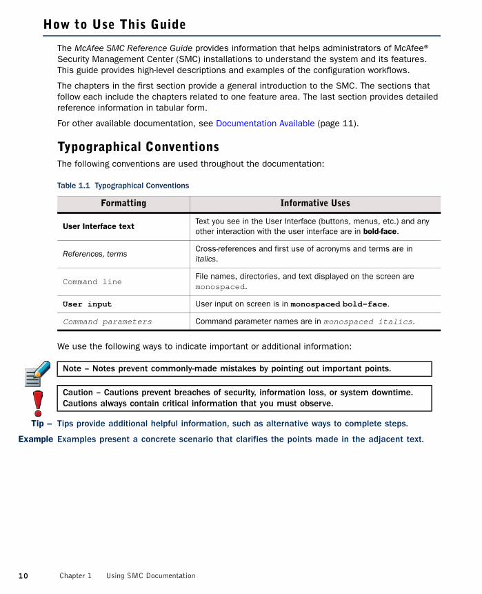
Typographical ConventionsThe following conventions are used throughout the documentation:
We use the following ways to indicate important or additional information:
Tip – Tips provide additional helpful information, such as alternative ways to complete steps.
Example Examples present a concrete scenario that clarifies the points made in the adjacent text.
Table 1.1 Typographical Conventions
Formatting Informative Uses
User Interface textText you see in the User Interface (buttons, menus, etc.) and any other interaction with the user interface are in bold-face.
References, termsCross-references and first use of acronyms and terms are in italics.
Command lineFile names, directories, and text displayed on the screen are monospaced.
User input User input on screen is in monospaced bold-face.
Command parameters Command parameter names are in monospaced italics.
Note – Notes prevent commonly-made mistakes by pointing out important points.
Caution – Cautions prevent breaches of security, information loss, or system downtime. Cautions always contain critical information that you must observe.
10 Chapter 1 Using SMC Documentation

Documentation Available
SMC documentation is divided into two main categories: Product Documentation and Support Documentation (page 12). Each SMC product has a separate set of manuals.
Product DocumentationThe table below lists the available product documentation.
PDF guides are available at https://www.stonesoft.com/en/customer_care/documentation/current/. The McAfee SMC Administrator’s Guide, and the Reference Guides and Installation Guides for McAfee Security Management Center, McAfee Firewall/VPN, McAfee IPS, and McAfee Layer 2 Firewall are also available as PDFs on the Security Management Center DVD.
Table 1.2 Product Documentation
Guide Description
Reference Guide
Explains the operation and features of the SMC comprehensively. Demonstrates the general workflow and provides example scenarios for each feature area. Available as separate guides for McAfee Security Management Center and McAfee Firewall/VPN, and as a combined guide for McAfee IPS and McAfee Layer 2 Firewall.
Installation Guide
Instructions for planning, installing, and upgrading the SMC. Available as separate guides for McAfee Security Management Center and McAfee Firewall/VPN, and as a combined guide for McAfee IPS and McAfee Layer 2 Firewall.
Online Help
Describes how to configure and manage the system step-by-step. Accessible through the Help menu and by using the Help button or the F1 key in any window or dialog. Available in the Management Client and the Web Portal. An HTML-based system is available in the SSL VPN Administrator through help links and icons.
Administrator’s Guide
Describes how to configure and manage the system step-by-step. Available as a combined guide for McAfee Firewall/VPN, McAfee IPS, and McAfee Layer 2 Firewall, and as separate guides for the SSL VPN and the IPsec VPN Client.
User’s GuideInstructions for end-users. Available for the IPsec VPN Client and the Web Portal.
Appliance Installation GuideInstructions for physically installing and maintaining McAfee®NGFW appliances (rack mounting, cabling, etc.). Available for all McAfee NGFW appliances.
11Documentation Available

Support DocumentationThe McAfee support documentation provides additional and late-breaking technical information. These technical documents support the SMC guide books, for example, by giving further examples on specific configuration scenarios.
The latest technical documentation is available at http://www.stonesoft.com/support/.
System RequirementsThe system requirements for running the McAfee Security Management Center can be found in the Security Management Center Release Notes available at http://www.stonesoft.com/en/customer_care/kb/.
Supported FeaturesNot all features are supported on all platforms. See the Appliance Software Support Table for more information.
Contact Information
For general information about SMC products, visit our web site at http://www.mcafee.com/.
12 Chapter 1 Using SMC Documentation

CHAPTER 2
INTRODUCTION TO THE SECURITY MANAGEMENT CENTER
This chapter describes the McAfee Security Management Center components and provides an overview of the main benefits of the centralized management system. This chapter also explains the basics of licensing the McAfee Security Management Center system components.
The following sections are included:
McAfee NGFW Solution (page 14)SMC Components (page 15)Main Benefits of the Security Management Center (page 18)Managing Licenses (page 19)
13

McAfee NGFW Solution
The McAfee Security Management Center (SMC) forms the core of the McAfee NGFW solution. The Security Management Center makes the McAfee NGFW solution especially well-suited to complex and distributed network environments. The Management Center configures and monitors all the components in the McAfee NGFW solution.
The centralized management system provides a single point of contact for a large number of geographically dispersed administrators. The unified management platform provides major benefits for organizations of all sizes:
• Interaction between the McAfee Firewall/VPN, McAfee IPS, McAfee Layer 2 Firewall, Master Engine, and Virtual Security Engine components in the same system creates security benefits by allowing automatic coordinated responses when a security threat is detected, providing instant blocking of unwanted traffic, and reducing the need for immediate human intervention.
• Multiple administrators can log in at the same time to efficiently configure and monitor all McAfee NGFW engines. The SMC provides a single user interface that allows unified configuration, monitoring, and reporting of the whole McAfee NGFW solution with the same tools and within the same user session.
• The reuse of configuration information across components in the system allows you to avoid the laborious and error-prone duplicate work of configuring the same details for all components individually or exporting and importing the configurations between multiple separate systems.
The SMC is designed to manage large installations and to be geographically distributed, so it is flexible and allows scaling up the existing components and adding new types of components to the system without sacrificing its ease-of-use.
14 Chapter 2 Introduction to the Security Management Center

SMC Components
The SMC components and their roles are illustrated below.
Illustration 2.1 SMC Components
One Security Management Center can manage a large number of Security Engines, Master Engines, and Virtual Security Engines. The distributed architecture allows deploying the system components effectively in different network environments. You can flexibly add, remove, and reposition SMC components according to your needs.
Table 2.1 SMC Components
Component Description
Management ClientsProvide a user interface for configuring, controlling, and monitoring the system. Connect to the Management Server.
Management ServersStore all configuration data, relay commands to the engines, and notify administrators of new alerts in the system.
Log ServersStore logs and correlate events detected by multiple security engines.
Web Portal ServersProvide restricted viewing of configuration information, reports, and logs.
Authentication ServersProvide user linking and user authentication services for end-user and administrator authentication.
NGFW Engines (Security Engines)
Management Server
Log Server
Web Portal Server
Authentication Server
Management Client
Web Portal
15SMC Components
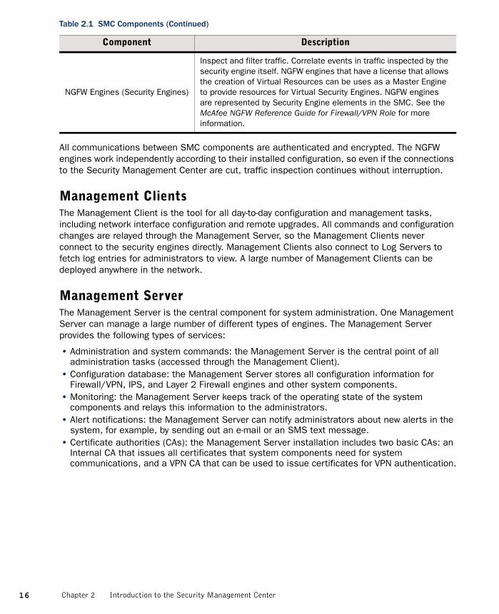
All communications between SMC components are authenticated and encrypted. The NGFW engines work independently according to their installed configuration, so even if the connections to the Security Management Center are cut, traffic inspection continues without interruption.
Management ClientsThe Management Client is the tool for all day-to-day configuration and management tasks, including network interface configuration and remote upgrades. All commands and configuration changes are relayed through the Management Server, so the Management Clients never connect to the security engines directly. Management Clients also connect to Log Servers to fetch log entries for administrators to view. A large number of Management Clients can be deployed anywhere in the network.
Management ServerThe Management Server is the central component for system administration. One Management Server can manage a large number of different types of engines. The Management Server provides the following types of services:
• Administration and system commands: the Management Server is the central point of all administration tasks (accessed through the Management Client).
• Configuration database: the Management Server stores all configuration information for Firewall/VPN, IPS, and Layer 2 Firewall engines and other system components.
• Monitoring: the Management Server keeps track of the operating state of the system components and relays this information to the administrators.
• Alert notifications: the Management Server can notify administrators about new alerts in the system, for example, by sending out an e-mail or an SMS text message.
• Certificate authorities (CAs): the Management Server installation includes two basic CAs: an Internal CA that issues all certificates that system components need for system communications, and a VPN CA that can be used to issue certificates for VPN authentication.
NGFW Engines (Security Engines)
Inspect and filter traffic. Correlate events in traffic inspected by the security engine itself. NGFW engines that have a license that allows the creation of Virtual Resources can be uses as a Master Engine to provide resources for Virtual Security Engines. NGFW engines are represented by Security Engine elements in the SMC. See the McAfee NGFW Reference Guide for Firewall/VPN Role for more information.
Table 2.1 SMC Components (Continued)
Component Description
16 Chapter 2 Introduction to the Security Management Center

Log ServerMultiple Log Servers can be deployed, which is particularly useful in geographically distributed systems. Log Servers provide the following types of services:
• Log data: Log Servers receive and store logs from other system components and make the data available for viewing and generating reports.
• Statistics and status data: Log Servers receive, relay, and store information about the operation of other system components and keep a record available for generating reports.
• Event correlation: Log Servers detect patterns of events in traffic inspected by multiple security engines.
Web Portal ServerThe Web Portal Server is a separately licensed optional component that can be used to provide restricted access to log data, reports, and policy snapshots. The Web Portal Server provides a web-based interface that users who have Web Portal user accounts can access with their web browsers.
Authentication ServerThe Authentication Server is a separately licensed optional component that can be used to provide user authentication services for end-user and administrator authentication. You must link users from an external directory server to the Authentication Server’s internal user database if you want to authenticate users with the authentication methods offered by the Authentication Server. The Authentication Server license defines the maximum number of named users for user linking in the Authentication Server’s user database. See the McAfee NGFW Reference Guide for Firewall/VPN Role for more information about directory services and user authentication.
The Authentication Server can be installed as a single Authentication Server or as an Authentication Server cluster. Only one Authentication Server or an Authentication Server cluster can be installed in each Security Management Center.
Additionally, the Authentication Server can provide user authentication services for the SSL VPN, and for third-party components. Each component that uses the authentication services provided by the Authentication Server must be defined as a RADIUS client in the Authentication Server properties. The Management Server and Firewalls with static IP addresses are automatically defined as RADIUS clients of the Authentication Server. The Authentication Server license defines the maximum number of RADIUS clients (excluding other SMC components).
17SMC Components

Main Benefits of the Security Management Center
Centralized Remote ManagementA centralized point for managing all system components simplifies the system administration significantly and allows combining information from different sources without having to integrate the components with an external system. The centralized management system is not an add-on; the system has been designed from the start to be centrally managed.
The main centralized management features in the Security Management Center include the following:
• Sharing configuration data in different configurations eliminates the need for duplicate work, which reduces the complexity of configurations and the amount of work required for making changes. For example, an IP address used in the configurations of several different security engines has to be changed only one time in one place because it is defined as a reusable element in the system.
• Remote upgrades can be downloaded and pushed automatically to several components. A single remote upgrade operation updates all necessary details on the security engines, including operating system patches and updates.
• Fail-safe policy installation with automatic rollback to prevent policies that prevent management connections from being installed.
• The integrated backup feature allows saving all system configurations stored on the Management Server in one manually or automatically run backup.
• Central access point for administrators with centralized access control. The Management Client requires no separate installation, because it can be made available centrally and be launched through a web browser. Several administrators can be logged in at the same time and simultaneously make changes to the system. Conflicting changes are automatically prevented. Administrator privileges can be easily adjusted in a highly granular way.
Support for Large-Scale InstallationsThe Security Management Center is scalable from managing a single security engine up to a system consisting of hundreds of components. Several Log Servers are usually required in larger systems, but a single Management Server can still effectively manage very large installations. The features that are specifically targeted at making large-scale installations easy to manage include the possibility to separate configurations into isolated Domains and to filter configuration definitions in and out of view based on user-defined categories.
High AvailabilityYou can optionally install one or more additional Management Servers. This requires a special Management Server license for multiple Management Servers. Additional Management Servers allow controlling the system without delays and without loss of configuration information if the active Management Server is damaged, loses power, or becomes otherwise unusable.
Log Servers can also be used as backups for each other to allow continued operation when a Log Server is lost. When a Log Server becomes unavailable, engines can automatically start sending new logs and monitoring data to another pre-selected Log Server. Log Servers do not automatically synchronize their data, but you can set up automatic tasks in the system for backing up important records.
18 Chapter 2 Introduction to the Security Management Center

Managing Licenses
The Management Server maintains the license files, which provide your system a proof of purchase. You receive your licenses as proof-of-license (POL) codes in a license delivery pack that is sent by e-mail. The proof-of-serial (POS) license code for McAfee NGFW appliances is printed on a label attached to the appliances. You can use your license code to log in to the License Center at https://my.stonesoft.com/managelicense.do to view and manage your licenses.
Generally, each SMC server and each Firewall/VPN engine, IPS engine, Layer 2 Firewall engine, and Master Engine must be separately licensed in your Security Management Center. Virtual Security Engines do not require their own licenses.
• The Security Management Center components must always be licensed by importing a license file that you create at the McAfee web site.
• Licenses for McAfee NGFW appliances may be generated automatically or you may also need to generate these licenses manually at the McAfee web site, depending on the appliance model and Management Server connectivity.
• License files for SSL VPN appliances can be imported and updated either through the appliances’ own local administration console or through the Management Client.
The use of some individual features is also limited by license.
All licenses indicate the latest version for which they are valid and are valid on all earlier software versions up to the version indicated. Licenses are by default automatically updated to the newest version possible for the component. If automatic license updates are not possible or disabled, you must generate new licenses manually before upgrading to a new major release.
License upgrades are included in maintenance contracts. If the maintenance contract of a component expires, it is not possible to upgrade the license to any newer version. Evaluation licenses are valid for 30 days. Purchased licenses do not expire unless otherwise noted.
19Managing Licenses

20 Chapter 2 Introduction to the Security Management Center

CHAPTER 3
SECURITY MANAGEMENT CENTER DEPLOYMENT
This chapter provides general guidelines for the McAfee Security Management Center deployment.
The following sections are included:
Overview of Security Management Center Deployment (page 22)Security Considerations (page 23)Positioning the Management Server (page 23)Positioning Log Servers (page 24)Positioning Management Clients (page 24)Example Deployment Scenario (page 25)
21

Overview of Security Management Center Deployment
Supported PlatformsThe McAfee Security Management Center (SMC) can be installed on standard Intel-compatible servers. The hardware requirements can be found in the supplementary technical documentation database at http://www.stonesoft.com/en/customer_care/kb/. Although the Web Start distribution of the Management Client is also officially certified to run only on the listed official platforms, it has been found to run satisfactorily on other platforms as well (including Mac OS X and additional Linux distributions), providing that the required version of JRE (Java Runtime Environment) is installed.
General Deployment GuidelinesThe basic Security Management Center installation consists of a Management Server, a Log Server, and Management Clients. It is possible to run the Management Server and the Log Server on the same machine in low-traffic environments. In larger environments, the components are run on dedicated servers. Several Log Servers may be needed in large or geographically distributed organizations. The Management Clients connect to the Management Server for configuring and monitoring the system and to Log Servers for browsing the log entries.
Table 3.1 General Guidelines for McAfee Security Management Center Deployment
SMC Component General Guidelines
Management ServerPosition on a central site where it is physically accessible to the administrators responsible for maintaining its operation.
Log ServersPlace the Log Servers centrally and/or locally on sites as needed based on log data volume, administrative responsibilities, etc.
Web Portal ServerThe Web Portal Server can be deployed in any location that has network access to the Management Server and the Log Servers.
Authentication ServerThe Authentication Server can be deployed in any location that has network access to the Management Server and the Log Servers. Nodes belonging to the same Authentication Server can be deployed in separate locations.
Management ClientsManagement Clients can be used from any location that has network access to the Management Server and the Log Servers.
22 Chapter 3 Security Management Center Deployment

Security Considerations
The information stored in the Security Management Center is highly valuable to anyone conducting or planning malicious activities in your network. Someone who gains administrator access to the Management Server can alter the configurations. The most likely way someone could achieve this is by exploiting weaknesses in the operating system or other services running on the same computer to gain administrator privileges in the operating system.
Consider at least the following points to secure the Management Server and Log Server:
• Prevent any unauthorized access to the servers. Restrict access to the minimum required both physically and with operating system user accounts.
• Take all necessary steps to keep the operating system secure and up to date.• We recommend that you do not run any third-party server software on the same computer with
the SMC servers.• We recommend placing the servers in a separate, secure network segment that does not
contain any third-party servers, and that you limit access to this network to specific authenticated users.
You can optionally use 256-bit encryption for the connection between Security Engines and the Management Server. This requires both the engines and the Management Server to be version 5.5 or higher. You must also use an Internal ECDSA Certificate Authority to sign certificates for SMC communication.
Positioning the Management Server
The Management Server is usually positioned on a central site at the corporate headquarters or data center, from where it can reach all other SMC components. The Management Server does not need to be located close to the administrators, as the Management Clients connect to the Management Server and Log Servers over the network using an encrypted connection.
We recommend using the same Security Management Center to manage all your NGFW engines. This unified approach simplifies managing physically distributed network environments and allows closer integration, for example, sending blacklist requests from IPS engines to Firewalls. The configuration information and log data can then be shared and used efficiently together. A single Management Server can manage a very large number of components efficiently. You can optionally install one or more additional Management Servers for a high availability setup. Only one Management Server is active at a time. The additional Management Servers function as standby Management Servers.
The Management Server also handles active alerts and alert escalation to inform the administrators of critical events. In an environment with multiple Management Servers, all active alerts are replicated between the Management Servers.
Caution – Secure the Management Server computer. Anyone who has administrator access to the operating system can potentially view and change any SMC configurations.
23Security Considerations

Positioning Log Servers
Log Servers store engine-generated logs and traffic captures. The transferred amounts of data can be substantial, so the primary concern for Log Server deployment is the number and throughput of the engine components that send data to the Log Server. Several Log Servers can be located both on a central site as well as at remote sites. A single shared Log Server can be sufficient for a number of remote sites with low traffic volumes, whereas a large office with very high volumes of network traffic may require even several Log Servers for efficient use.
Positioning Management Clients
The Management Client provides a graphical user interface for managing and monitoring the entire system. Management Clients can be used at any location from which there is access to the Management Server for system administration and the Log Servers for log and alert browsing. The Firewall/VPN and IPS engines are managed through the Management Server, so the Management Client never connects directly to the security engines.
The Management Clients can be installed locally or launched through Java Web Start. The main difference between the installations is that locally installed clients are also upgraded locally and individually, whereas the Web Start installation is updated centrally and the individual Management Client installations are then automatically upgraded without user intervention. Additionally, the local installation is possible only on officially supported Security Management Center platforms, whereas running the Web Start version is usually possible also on other platforms that have the required version of JRE (Java Runtime Environment) installed.
24 Chapter 3 Security Management Center Deployment

Example Deployment Scenario
In this example deployment, a company has operations in three different locations. There are some security engines and administrators who are responsible for managing the local equipment at each site.
Illustration 3.1 Example of a Distributed Security Management Center Deployment
Site A is the main site of the company. The active Management Server that manages all local and remote components is located at Site A, since the main administrators responsible for maintaining the server are stationed there. There are also two separate Log Servers at Site A, since there are a high number of security engines at this site, producing a high volume of logs. The Log Servers also work as backup servers for each other.
Site B is a large branch office that is also designated as the disaster recovery site for the main site, although just the most important services are duplicated. This site has a moderate number of security engines. A separate Log Server is installed at Site B to ensure swift log browsing for the local administrators.
Site C is a small branch office that has only a few security engines. There is a single local administrator who is an infrequent user of the SMC. There are no Security Management Center components at Site C; the local security engines send their data to the Log Servers at Site A.
Internet
Management Server
Combined local Log Server and additional Management Server
Management Clients
Management Clients
Management ClientLog Servers
Site A
Site B
Site C
25Example Deployment Scenario

26 Chapter 3 Security Management Center Deployment

27
CONFIGURATION TOOLS
In this section:
Management Client Basics - 29
Introduction to Elements in the SMC - 37
Expressions - 49

28
CHAPTER 4
MANAGEMENT CLIENT BASICS
The Management Client is the single graphical tool that is used for setting up, managing, and monitoring all features in the SMC.
The following sections are included:
Introduction (page 30)System Monitoring Tools (page 30)Configuration Views (page 36)The Policy Editing View (page 36)
29
Introduction
The Management Client is the tool for configuring, controlling, and monitoring the SMC. The Firewall/VPN engines, Layer 2 Firewall engines, IPS engines, Master Engines, and Virtual Security Engines are managed through the Management Client. You can also monitor, license, upgrade, and change the operating status of SSL VPN engines through the Management Client. Third-party devices can also be monitored through the Management Client.
This chapter gives an general overview to the different views in the Management Client, but does not contained detailed instructions for using the various tools. For detailed steps, see the Management Client Online Help or the McAfee SMC Administrator’s Guide.
System Monitoring Tools
The Domain OverviewIf the configurations are divided in different administrative Domains, the Domain Overview is displayed as the first view after login to administrators who have privileges for several domains. You can then select the Domain that you want to manage. See Domains (page 65) for more information.
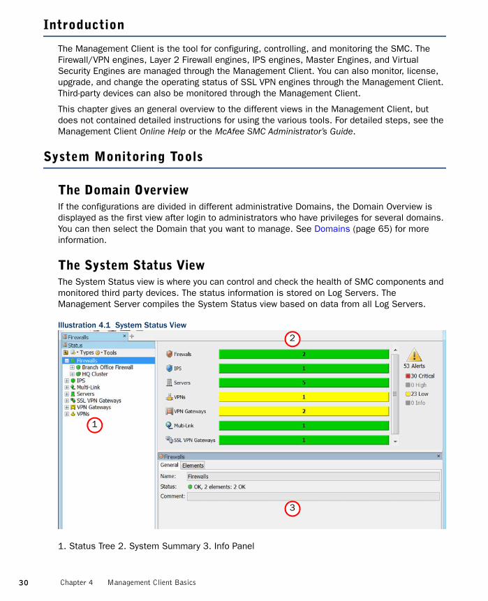
The System Status ViewThe System Status view is where you can control and check the health of SMC components and monitored third party devices. The status information is stored on Log Servers. The Management Server compiles the System Status view based on data from all Log Servers.
Illustration 4.1 System Status View
1. Status Tree 2. System Summary 3. Info Panel
1
2
3
30 Chapter 4 Management Client Basics

The System Summary shows the status of the entire system at a glance. You can view more details by clicking the displayed status information. The alert summary displayed here refers to Active alerts (alerts that have not been acknowledged).
The Status Tree displays all components in your system that can be monitored, and also those Diagrams and Groups that contain monitored elements. Selecting an element in the Status Tree switches the main view to graphical monitoring.
Illustration 4.2 Graphical Monitoring
The automatic graphical monitoring diagram shows the selected component’s status and the status of its connections with other SMC components.
When you select an individual engine node in the Status tree, the main view switches to hardware monitoring with details on the status of network ports.
In this view, more detailed information is shown in the Info panel for network interfaces and hardware (appliance) status.
The Info PanelThe Info panel is shown by default in most views. In addition to element details, the Info panel shows the most important status information for components.
Node status on clusters
Cluster status
Connectivity status with other SMC components
31System Monitoring Tools

OverviewsOverviews are customizable system monitoring views. In addition to status information, you can add various statistics related to the traffic and the operating state of components. You can display information in various ways, such as tables, maps, and different types of charts. Statistics can trigger an alert when the value of a monitored item reaches a limit you set.
Illustration 4.3 Example Overview
32 Chapter 4 Management Client Basics

The Logs ViewThe Logs view can show entries generated by any SMC components and third-party components that send data to the SMC. The logged data includes alert and audit entries (depending on administrator rights). You can filter the display by any combination of details that exist in the records. There are four different arrangements: Records, Statistics, Details, and Log Analysis.
The Records arrangement allows you to view selected details of many entries at a time. The columns in the table are fully customizable.
Illustration 4.4 Logs View in the Records Arrangement
The Statistics arrangement allows you to generate basic summaries of the log data currently displayed in the Logs view similar to the charts in overviews, with a possibility to drill in to the logs through individual chart items.
33System Monitoring Tools

Illustration 4.5 Statistics Arrangement
The Details arrangement gives an overview of an individual log entry.
Illustration 4.6 Details Arrangement
34 Chapter 4 Management Client Basics

The Log Analysis arrangement provides various tools with which to analyze and visualize log data. You can, for example, combine logs by service or situation, sort logs by column type, view the data as charts or diagrams. This makes it easier to notice patterns and anomalies in traffic.
Illustration 4.7 Log Analysis Arrangement
ReportsThe reporting feature allows you to create statistical summaries based on log data and stored statistical data. The Reports can be viewed in the Management Client or exported automatically or manually. See Reports (page 103) for more information.
35System Monitoring Tools
Configuration Views
Configuration views allow you to view, modify, and add configuration information in the system.
There are different Configuration views for different tasks. In all views, the main level of the tree contains the elements that need to be changed most often. Supporting and less frequently changed elements can be found under the Other Elements branch.
• The Security Engine Configuration view allows you to manage Security Engine elements and configure security engine policies.
• The User Authentication Configuration view allows you to configure user authentication and directory services, and manage user accounts.
• The VPN Configuration view allows you to configure Gateways, route-based VPN and VPN connections.
• The Administration Configuration view allows you to manage the system, including access rights, updates, licenses, administrator accounts, alert escalation, etc.
• The Monitoring Configuration view allows you to create statistical reports, diagrams, configure additional monitoring related features (such as third party device monitoring) etc.
See Introduction to Elements in the SMC (page 37) for more information.
The Policy Editing View
The instructions for traffic handling are stored as rules in Policy elements. You can open policies in two modes. Any number of administrators can simultaneously check the rules in the Preview mode. When you open the policy in the Edit mode, the policy is locked for you exclusively.
The Policy Editing View has tabs for the different types of rules in the policy and a side panel for selecting and creating elements that you use in the rules. The policy elements and the different types of rules are discussed in the McAfee NGFW Reference Guide for Firewall/VPN Role and the McAfee NGFW Reference Guide for IPS and Layer 2 Firewall Roles.
36 Chapter 4 Management Client Basics

CHAPTER 5
INTRODUCTION TO ELEMENTS IN THE SMC
The Security Management Center stores configurations as reusable elements. All configuration data you enter into the system is stored in elements of different types.
The following sections are included:
Introduction to Elements (page 38)Administration (page 38)Security Engine Configuration (page 40)User Authentication Configuration (page 41)Monitoring (page 42)Network Elements (page 44)Services (page 45)Situations (page 45)VPN Configuration (page 47)
37

Introduction to Elements
Apart from a few minor exceptions, all configurations are created in the Security Management Center, where information is stored as reusable elements. For example, the Security Engines, traffic inspection policies, IP addresses, log filters, backups, and the licenses for the system components are all displayed as elements.
Different element types are provided for different concepts. The elements in the system define information both for adjusting the traffic inspection policies and for managing the system. This chapter gives you a brief description of each type of element. You can open task-specific configuration views through the Management Client’s Configuration menu. Alternatively, the individual configuration views can be accessed through the Configuration icon in the main toolbar.
Administration
The table below lists the types of elements that are used for system administration.
Table 5.1 Types of Elements For System Administration
Element Type Explanation
Access Rights
Access Control Lists
Sets of elements that you can grant to one or more administrator accounts when assigning administrator privileges.
Administrator Roles
Sets of actions that administrators are allowed to carry out both globally and/or specifically on some set of elements.
Administrators SMC administrator accounts.
Web Portal Users User accounts for the Web Portal.
Alert Configurations
Alert Chains Lists of administrators and contact methods for escalating Alerts.
Alert PoliciesRules for choosing which Alerts are escalated using which Alert Chain.
Alert Senders System components that can send Alerts.
AlertsLabels for Alerts that help in separating different Alerts from each other in Alert escalation.
Policy SnapshotsSaved versions of the alert configuration. Created each time you install or refresh the Alert Policy on a Domain.
Bookmarks User-created shortcuts to views in the Management Client.
Licenses The components’ licenses (proof of purchase).
Tasks
Definition System maintenance Tasks and Task definitions.
HistoryHistory of running and executed Tasks both launched by users and generated by the system.
Tools Profiles User-configured additional commands/tools for components.
38 Chapter 5 Introduction to Elements in the SMC

Other Elements
BackupsManagement Server, Log Server, and Authentication Server backups.
CategoriesAllow filtering the view in the Management Client to a subset of elements.
DomainsCreate boundaries for managing elements and configurations based on administrator configurations.
Engine UpgradesPackages for remote upgrades that have been manually or automatically imported into the system.
GeolocationsUsed for illustrating the geographical location of IP addresses (for example, in logs and diagrams).
Internal Certificate Authorities
Management Server’s Internal Certificate Authority that issues all certificates that components need for system communications. A new Internal Certificate Authority is automatically generated before the old one expires.
Internal Certificates
Certificates that are used in communications between the system components.
LocationsUsed for defining contact addresses when NAT (IP address translation) is applied to communications between system components.
TrashStores elements that you have deleted. You can permanently delete elements that have been moved to the Trash.
UpdatesDynamic update packages that update McAfee-supplied definitions in your installation. Most of the content is Situations (used in deep packet inspection).
Web Portal Localizations
Used for translating the Web Portal between languages.
Table 5.1 Types of Elements For System Administration (Continued)
Element Type Explanation
39Administration
Security Engine Configuration
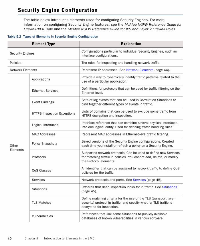
The table below introduces elements used for configuring Security Engines. For more information on configuring Security Engine features, see the McAfee NGFW Reference Guide for Firewall/VPN Role and the McAfee NGFW Reference Guide for IPS and Layer 2 Firewall Roles.
Table 5.2 Types of Elements in Security Engine Configuration
Element Type Explanation
Security EnginesConfigurations particular to individual Security Engines, such as interface configurations.
Policies The rules for inspecting and handling network traffic.
Network Elements Represent IP addresses. See Network Elements (page 44).
Other Elements
ApplicationsProvide a way to dynamically identify traffic patterns related to the use of a particular application.
Ethernet ServicesDefinitions for protocols that can be used for traffic filtering on the Ethernet level.
Event BindingsSets of log events that can be used in Correlation Situations to bind together different types of events in traffic.
HTTPS Inspection ExceptionsLists of domains that can be used to exclude some traffic from HTTPS decryption and inspection.
Logical InterfacesInterface reference that can combine several physical interfaces into one logical entity. Used for defining traffic handling rules.
MAC Addresses Represent MAC addresses in Ethernet-level traffic filtering.
Policy SnapshotsSaved versions of the Security Engine configurations. Created each time you install or refresh a policy on a Security Engine.
ProtocolsSupported network protocols. Can be used to define new Services for matching traffic in policies. You cannot add, delete, or modify the Protocol elements.
QoS ClassesAn identifier that can be assigned to network traffic to define QoS policies for the traffic.
Services Network protocols and ports. See Services (page 45).
SituationsPatterns that deep inspection looks for in traffic. See Situations (page 45).
TLS MatchesDefine matching criteria for the use of the TLS (transport layer security) protocol in traffic, and specify whether TLS traffic is decrypted for inspection.
VulnerabilitiesReferences that link some Situations to publicly available databases of known vulnerabilities in various software.
40 Chapter 5 Introduction to Elements in the SMC

User Authentication Configuration
The table below introduces elements used for configuring user authentication and directory services. For more information on configuring authentication features, see the McAfee NGFW Reference Guide for Firewall/VPN Role.
Other Elements(cont.)
Engine Properties
Anti-Spam Settings for identifying and blocking e-mail messages as spam.
Antispoofing Rules for preventing IP address spoofing.
HTML Pages Profiles
Define the look of the login page, challenge page, and status page shown to end-users who authenticate through a web browser.
Routing Rules for routing traffic.
SNMP AgentsConfiguration information for sending SNMP traps to external components about system events related to Security Engines.
User AgentsRepresent a software component installed on a Windows server to associate users with IP addresses.
User Responses
Settings for notifying end-users about different policy actions.
CertificatesClient Protection Certificate Authorities, Server Credentials, and Trusted Certificate Authorities used in HTTPS inspection.
Table 5.2 Types of Elements in Security Engine Configuration (Continued)
Element Type Explanation
Table 5.3 Types of Elements in User Authentication Configuration
Element Type Explanation
Authentication MethodsConfigured authentication methods for end-user and administrator authentication. Used in rules that require end-user authentication.
Servers
Active Directory Servers, Configured Authentication Servers, LDAP Servers, RADIUS Authentication Servers, and TACACS+ Authentication Servers for end-user and administrator authentication and directory services.
UsersEnd-users stored in the internal LDAP database, the Authentication Server’s LDAP database, and/or an external LDAP database. Used in rules that require end-user authentication.
Other Elements
Configuration Snapshots
Saved versions of Authentication Server configurations. Created each time you apply the configuration on the Authentication Server.
SMTP ServersSMTP servers that send e-mail or SMS messages about changes to user accounts to end-users. The same SMTP Servers can also be used to send Alerts to Administrators.
CertificatesTrusted Certificate Authorities that issue certificates presented by service providers, Pending Certificate Requests, and server credentials.
41User Authentication Configuration
Monitoring
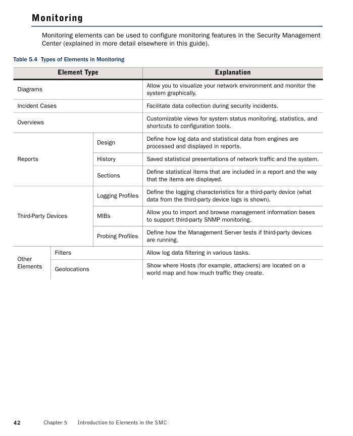
Monitoring elements can be used to configure monitoring features in the Security Management Center (explained in more detail elsewhere in this guide).
Table 5.4 Types of Elements in Monitoring
Element Type Explanation
DiagramsAllow you to visualize your network environment and monitor the system graphically.
Incident Cases Facilitate data collection during security incidents.
OverviewsCustomizable views for system status monitoring, statistics, and shortcuts to configuration tools.
Reports
DesignDefine how log data and statistical data from engines are processed and displayed in reports.
History Saved statistical presentations of network traffic and the system.
SectionsDefine statistical items that are included in a report and the way that the items are displayed.
Third-Party Devices
Logging ProfilesDefine the logging characteristics for a third-party device (what data from the third-party device logs is shown).
MIBsAllow you to import and browse management information bases to support third-party SNMP monitoring.
Probing ProfilesDefine how the Management Server tests if third-party devices are running.
Other Elements
Filters Allow log data filtering in various tasks.
GeolocationsShow where Hosts (for example, attackers) are located on a world map and how much traffic they create.
42 Chapter 5 Introduction to Elements in the SMC

Other Elements(cont.)
Monitoring Snapshots
BlacklistSaved version of blacklist entries for a Security Engine. Created when you save a Blacklist Snapshot in the Blacklist view.
ConnectionsSaved version of connection entries for a Security Engine. Created when you save a Connections Snapshot in the Connections view.
LogsSaved version of log, alert and audit entries for a Security Engine. Created when you save a Logs Snapshot in the Logs view.
RoutingSaved version of routing entries for a Security Engine. Created when you save a Routing Snapshot in the Routing view.
UsersSaved version of active users for a Security Engine. Created when you save a User Snapshot in the Users view.
VPN SAsSaved version of active VPN SAs for a Security Engine. Created when you save a VPN SA snapshot in the VPN SAs view.
Network Elements Represent IP addresses. See Network Elements (page 44).
Overview TemplatesTemplates that allow you to create a statistical overview with predefined information selected for the view.
Table 5.4 Types of Elements in Monitoring (Continued)
Element Type Explanation
43Monitoring

Network Elements
Network elements represent IP addresses in Security Engine configurations.
Table 5.5 Types of Network Elements
Element Type Explanation
Address RangesDefine a set of consecutive IP addresses between a start address and end address that you define.
Aliases
Context-dependent elements with no fixed value. The value is defined per engine and is determined when a policy containing the Alias is installed. See the McAfee NGFW Reference Guide for Firewall/VPN Role or the McAfee NGFW Reference Guide for IPS and Layer 2 Firewall Roles for more information.
Domain NamesThe name of an Internet domain that is automatically resolved by a Security Engine to all the IP addresses associated with the domain.
ExpressionsAllow defining IP addresses using logical operators, which simplifies the definition of complex sets of addresses. See Expressions (page 49).
GroupsAllow collecting together other Network Elements of any type. Represents all IP addresses defined in the included elements.
Hosts Represent a single IP address.
Networks Represent a complete (sub)network of addresses.
RoutersRepresent a next-hop router in configurations where specifically required. In policies, represent a single IPv4 and/or IPv6 address.
Security EnginesConfigurations particular to individual Security Engines, such as the interface configuration.
ServersRepresent an SMC server or an external server that provides a service to the system. In policies, represent a single IP address.
SSL VPN GatewaysInformation required to integrate an individual SSL VPN appliance with the SMC for monitoring and basic commands.
Traffic HandlersConfigure outbound and inbound traffic management features (load balancing and high availability).
Zones
Interface reference that can combine several network interfaces of Security Engines into one logical entity. Used for defining interface matching requirements in traffic handling rules in policies.
44 Chapter 5 Introduction to Elements in the SMC

Services
Service elements are used in Access rules to match traffic and to set parameters for handling the traffic. There are predefined system Service elements for official (IANA-reserved) and well-known protocols and services (such as DNS, FTP, HTTP, etc.). You can also create your own custom Service elements to specify a port that is not predefined or to define custom options for handling some types of traffic. See the McAfee NGFW Reference Guide for Firewall/VPN Role and the McAfee NGFW Reference Guide for IPS and Layer 2 Firewall Roles for more information.
Situations
Situation Elements are used in Inspection rules to define patterns that deep packet inspection looks for in traffic. This tree is constructed differently compared to most other trees.
The Situations tree contains several alternative groupings, so most Situations are shown in several places. The groupings allow you to easily find Situations that are specific to the task at hand. For example, Situations specific to the HTTP protocol (some of which are specific to particular web browsers) are stored in SituationsBy TypeTraffic IdentificationBrowsers.
Some branches are groupings that you can add to yourself. You can use most of these branches in Inspection rules. The Situation Type groupings are used as the basis for the tree-based Inspection rules configuration in Inspection Policy elements.
Table 5.6 Types of Services
Element Type Explanation
GroupGroups of services that contain the Service elements that together fulfill a certain role (for example, the services needed to allow IPsec VPN connections).
ICMP Identifies the message by the ICMP Type and Code fields.
IP-proto Identifies the protocol by the IP header Protocol field.
SUN-RPCIdentifies the Sun remote procedure call (RPC) service by the program identifier.
TCPIdentifies the service by the TCP header Source Port and/or Destination Port fields.
UDPIdentifies the service by the UDP header Source Port and/or Destination Port fields.
With ProtocolDefault Services that contain Protocols that have default parameters set to typically used values.
45Services

Situations and their groupings are updated in dynamic update packages. The table below lists the default branches at the time of writing this document. See the McAfee NGFW Reference Guide for Firewall/VPN Role and the McAfee NGFW Reference Guide for IPS and Layer 2 Firewall Roles for more information.
Table 5.7 Default Groupings of Situations at the Time of Publishing This Document
Tree Branch Explanation
All Situations All Situations in the system without any grouping.
By Context
Anti-Virus Events triggered in the virus scanning on the UTM.
Correlations Correlation Situations for detecting patterns in event data.
DoS Detection Situations for detecting DoS (denial-of-service) attacks.
FilesSituations based on identifying file types from traffic. Content identified on the basis of file type fingerprints is redirected to appropriate file streams.
Protocols Situations that identify protocols from traffic.
Scan Detection Situations for detecting network scans.
System System-internal events.
By Tag
By Hardware
Situations that detect something specific to a particular hardware platform (for example, an attempt to exploit a known vulnerability that only works on a particular platform), grouped by platform (for example, x86 (32-bit) or x86-64 (64-bit)).
By Operating System
Situations that detect something specific to a particular operating system, grouped by operating system (for example, Windows (for all Windows versions) or Windows 2000).
By Situation Tag
Free-form grouping for some special use cases. The Recent Updates branch is especially useful, as the branches dynamically list Situations that have been recently added to the system in the 1-5 most recent dynamic update packages (this helps in tuning your policies).
By SoftwareSituations that detect something specific to a particular software, grouped by brand or product name (for example, Adobe Acrobat or Microsoft Office).
By TypeThese Situations are shown as the main Rules tree in the Inspection rules.
By VulnerabilitySituations that detect attempts to exploit known vulnerabilities grouped by vulnerability name.
Custom SituationsCustom Situations that the administrators create. Custom Situations may also appear in the other branches.
46 Chapter 5 Introduction to Elements in the SMC

VPN Configuration
The table below introduces elements used for configuring VPNs. For more information on configuring VPNs, see the McAfee NGFW Reference Guide for Firewall/VPN Role.
Table 5.8 Types of Elements in the VPN Configuration
Element Type Explanation
GatewaysConfigurations particular to individual VPN Gateways, such as IP address information.
Route-Based VPNConfigurations particular to VPN tunnels between Firewall interfaces that are designated as tunnel end-points.
VPNsConfigurations particular to a particular VPN between two or more VPN gateways.
Other Elements
Certificates
Gateway Certificates
Information on certificates that Firewall/VPN engines use as identification in VPNs.
VPN Certificate Authorities
Certificate issuers whose signature is accepted as proof of identity on certificates in one or more VPNs.
Profiles
Gateway ProfilesInformation on the capabilities of particular types and versions of VPN gateway devices. Allow automatic configuration validation.
Gateway SettingsAdvanced global Firewall/VPN engine settings mainly related to VPN performance tuning.
VPN ProfilesThe main authentication, encryption, and integrity checking settings for VPNs.
47VPN Configuration

48 Chapter 5 Introduction to Elements in the SMC

CHAPTER 6
EXPRESSIONS
Expressions are elements that allow creating simple definitions for representing complex sets of IP addresses through the use of logical operands.
The following sections are included:
Introduction to Expressions (page 50)Operands (page 50)Expression Processing Order (page 52)Grouping Operands Using Parentheses (page 52)Nesting Expressions (page 53)
49

Introduction to Expressions
Expression is an element that combines other network elements (IP addresses) with logical operands. Expressions make it easier to define complex sets of network resources, even though you can arrive at the same definitions without expressions. For example, a single, simple expression can include a whole network except for a few individual IP addresses scattered throughout the address space. Otherwise, several Address Range elements could be needed to define the same set of IP addresses.
The expressions consist of the following parts:
• Parentheses group sets of elements and define the processing order in the same way as they do in mathematical equations. The parentheses in expressions are always the basic curved type “(” and “)”.
• Negation operands take a set and form a new set that includes every possible element except the ones in the original set. Negations are expressed with “~”.
• Intersection operands take two sets and forms a new set that includes only those IP addresses that are found in both sets. Intersections are expressed with “”.
• Union operands combine two sets and form a new set that includes every IP address in both sets. Unions are expressed with “”.
Next, we explain these concepts and their use in more detail, starting with operands.
Operands
Negation
Illustration 6.1 Graphical Representation of a Negation
The negation operand can be understood just based on common language use: it corresponds to the word “NOT”. For example, ~1.2.3.4 (negation of IP address 1.2.3.4) includes all other possible (IPv4) addresses except the IP address 1.2.3.4. As you see, negations are a good way to create a simple element that includes large IP address spaces with some exceptions. Usually, the negation will appear in constructions such as this: 192.168.10.0/24 ~192.168.10.200. This basically means “include all addresses in network 192.168.10.0/24, except do not include address 192.168.10.200”. This definition utilizes the intersection operand, which is explained next. We will return to this same example to explain the intersection part of the equation. Also, the section explaining the union operand will return to this example once more to explain why a union operand is not appropriate here.
Negation excludes a subset
Address space to which the negation applies
50 Chapter 6 Expressions

Intersection
Illustration 6.2 Graphical Representation of an Intersection
Intersection is perhaps the least intuitive of the operands used in expressions, but it is still quite simple in concept: it means “include only those IP addresses that are a part of both sets”. For example, we could intersect two address ranges, A (192.168.10.200 – 192.168.10.300) and B (192.168.10.250 – 192.168.10.350). The expression reads A B and it resolves to the following IP addresses: 192.168.10.250 – 192.168.10.300 (the IP addresses that appear in both ranges).
We now return to the previous example on the negation operand, where an intersection was also used: 192.168.10.0/24 ~192.168.10.200. On the left side, there is a specific network that we intersect with the right side that contains all possible IP addresses except one IP address. The intersection resolves to the IP addresses that the left side and the right side have in common. These include the IP addresses in network 192.168.10.0/24 except the one IP address that is specifically excluded on the right side of the equation. As shown here, intersections allow us to make expressions more specific. The next operand we present does the opposite.
Union
Illustration 6.3 Graphical Representation of a Union
The common language equivalent for the union operand is the word “AND”. The union operand’s role is to widen the scope of the expression. For example, the expression 1.2.3.0/24 2.3.4.0/24 simply includes all of the IP addresses in the two networks. As evident from this example, using unions is basically the same as if you simply include the elements in the same Group element. For this reason, unions are usually not the only operand in an expression, and perhaps a better example would be: ~192.168.1.1 ~192.168.1.255 (include all IP addresses except the two IP addresses mentioned), although this example is quite wide in scope and may perhaps need a further restriction to become practical (such as an intersection with the network 192.168.1.0/24 to include only addresses in that network).
Unions do have the potential to become too wide in scope if you are not careful. In the preceding text, we used the example expression: 192.168.10.0/24 ~192.168.10.200. If we replace the intersection (“”) with a union (“”) in that example, the expression then includes
Address space A Address space B
IP addresses that are in common = intersection
Union includes everything: all IP addresses in both sets combined
51Operands

all addresses from the left side (network 192.168.10.0/24) and all addresses from the right side (all IPv4 addresses except for one). The expression includes even the single IP address that is excluded on the right side, since it is part of the network on the left side. The result corresponds to the default “Any Network” element that matches all possible IP addresses. The processing order of the operands is also a factor in this result. This is explained next.
Expression Processing Order
The processing order of expressions is fixed. As in mathematical equations, items inside parentheses are always resolved before other comparisons. Next, the operands are processed by type: first the negations, then intersections, and last the unions.
For example, the expression A (B C) D is processed like this:
1. The formula between parentheses is solved first (the union of B and C). If we mark this result with X, the expression will then look like this: A X D.
2. Next, the negation is processed, inverting the value of X. We will mark this with Y like this: A Y D.
3. Next, the intersection between Y and D is resolved. We will mark that result with Z, and now the result looks like this: A Z.
4. Finally, the union of A and Z gives us the actual value that the expression represents (the full contents of both A and Z).
As shown here, the order in which the operand-value combinations appear in the expression have no significance to the order of processing. The only way to change the processing order is by using parentheses as explained next.
Grouping Operands Using Parentheses
Parentheses allow grouping the expression so that the operands you add are processed in a non-standard order. Operands inside parentheses are always processed before other operands. Parentheses can also be placed inside parentheses, in which case the operands are processed starting from the innermost parentheses.
For example, we can change the example from the previous section (Expression Processing Order) by adding a set of parentheses like this: (A (B C)) D. With the two sets of parentheses, the inner parentheses are processed first (B C as before), the negation is processed next (X as before), but then the outer parentheses are processed next instead of processing the intersection, changing the result. If (B C) results in Y (as before), then the expression will look like this: (A Y) D. The order of processing is then different than without the parentheses: instead of intersecting Y and D, the expression performs a union of A and Y and the intersection is then the last operand to be processed.
Complicated expressions with extensive use of parentheses can become difficult to read and edit. In these situations, nested expressions may sometimes be a better option.
52 Chapter 6 Expressions

Nesting Expressions
You can nest expressions by placing other expressions inside an expression. Nesting is a good way to simplify the creation of complex expressions. When you construct complex expressions from smaller incremental units, you can more easily find and fix problems. You can also reuse the smaller units in other expressions or policies as appropriate. Arguably, the expressions are also easier to read and edit when broken down into smaller units.
For example, if we want to create an expression that includes all IP addresses in three networks, except for one IP address in each, we end up with quite a long expression: (192.168.1.0/24 192.168.1.1) (192.168.2.0/24 192.168.2.1) (192.168.3.0/24 192.168.3.1). Instead of creating just one expression, it may make more sense to create several expressions: one for each set of parentheses above (for example, Expression A: 192.168.1.0/24 192.168.1.1) and then add either an expression that collects those three expressions together like this:Expression A Expression B Expression C or simply create a Group element that contains the three expressions. All three sub-expressions can be used individually or easily combined in other ways as needed, for example, Expression A Expression C. Naturally, when changes are made to an expression used inside some other expression, the definitions are updated in both places.
You can also create expressions that you use as templates for creating new expressions: when you insert an expression into another expression, you have the choice of extracting the contents from the expression instead of just inserting the expression. Extracting the contents allows you to make further changes and additions to the expression you insert. Extracting the contents also removes the link between the expressions, so changes are not propagated if the inserted expression is later changed.
53Nesting Expressions

54 Chapter 6 Expressions

55
ADMINISTRATION TOOLS
In this section:
Administrator Accounts - 57
Domains - 65
Categories - 71

56

CHAPTER 7
ADMINISTRATOR ACCOUNTS
Administrator accounts define administrator rights in the Security Management Center.
The following sections are included:
Overview of Administrator Accounts (page 58)Configuration of Administrator Accounts (page 58)Using Administrator Accounts (page 62)
57

Overview of Administrator Accounts
You can define administrator rights for each administrator. You can give each administrator different privileges globally, for specific administrative Domains, for specific groups of elements, and even for individual elements. Depending on the element, there are different levels of access that you can grant.
The Management Server keeps track of all the elements to make sure that administrator actions are limited by the rights defined in the administrator account. Administrators can modify an element only if they are allowed to modify all the configurations where the element is used. In addition to the defined privileges, the Management Server also prevents administrators from deleting elements that are still used in some other configuration, from editing the same Policy element simultaneously, and from making conflicting changes to the same element.
Configuration of Administrator Accounts
Two types of elements represent administrator accounts in the Security Management Center:
• Administrator elements define accounts for administrators who are allowed to manage elements through the Management Client and view information in the Web Portal.
• Web Portal User elements define accounts for users who are allowed to view information in the Web Portal. These are discussed in Creating Web Portal User Accounts (page 62). The Web Portal Server is a separately licensed component.
Illustration 7.1 shows the elements used with Administrator elements.
Illustration 7.1 Elements for Administrator Account Definitions
• Administrator Roles define sets of allowed actions.• Access Control Lists contain elements and allow you to more easily apply the Administrator
Roles to several engines and policies. There are some default Access Control Lists in the system that are automatically populated and can represent additional element types.
• If an administrator is allowed to view logs, you can use Filters to select which logs are displayed to the administrator.
• If you use administrative Domains, you can give administrators access to any number of Domains.
Administrator Roles
Administrator
Access Control Lists
FiltersDomains
Security Engines and Policies
Security Engines and Policies
58 Chapter 7 Administrator Accounts

Default ElementsThere are several predefined Administrator Roles and Access Control Lists that help you configure Administrator privileges. You cannot modify the predefined elements.
Table 7.1 describes the predefined Administrator Roles that you can optionally use instead of or in addition to customized Administrator Roles you create. All privileges listed here are always applied to a specific set of elements that you define.
All elements automatically belong to one or several predefined Access Control Lists in addition to the Access Control Lists you create yourself.
Table 7.1 Predefined Administrator Roles
Administrator Role Privileges Given
Viewer View the properties of elements.
OwnerView the properties, and edit and delete elements. When an administrator creates an element, the administrator is automatically set as an Owner of that element.
OperatorView the properties of elements, send commands to engines, refresh and upload policies, and browse logs and alerts (if applied to components that send logs).
Editor Operator privileges and additional privileges to create, edit, and delete elements.
Table 7.2 Predefined Access Control Lists
Access Control List Description
ALL Elements All elements that are defined in the system.
ALL DomainsAll Domain elements in the system. Can be used with Administrator elements only if Domain elements have been configured.
ALL Administrators
All elements of the type mentioned in the name of the Access Control List.
ALL Firewall Policies
ALL Firewalls
ALL Incident Cases
ALL Inspection Policies
ALL IPS Policies
ALL Layer 2 Firewall Policies
ALL Layer 2 Firewalls
ALL SSL VPN Gateways
ALL Third Party Devices
59Configuration of Administrator Accounts

The contents of the Access Control Lists are Domain-specific if Domain elements have been configured in the system. For example, in the Shared Domain, ALL IPS Policies refers to all the IPS Policies that belong to the Shared Domain.
Configuration WorkflowThe following sections provide an overview of the configuration tasks. Detailed step-by-step instructions can be found in the Management Client Online Help or the McAfee SMC Administrator’s Guide.
Task 1: Create a New Administrator RoleAdministrator Roles define a set of actions for which the administrator has permissions. Each administrator can have several different Administrator Roles applied to different sets of elements. There are some default Administrator Roles, but if you want to customize the privileges in any way, you must create custom Administrator Role elements.
The Administrator Role contains a fixed list of privileges that you can activate. Select only the minimum necessary permissions for each role. Administrators who are allowed to modify administrator accounts can freely give themselves any additional privileges.
Task 2: Create a New Access Control ListAccess Control Lists define granted elements. The Access Control Lists that you create can include engines and policies. Other elements are handled using the default Access Control Lists. You use the Access Control Lists to define the elements to which the privileges in each Administrator Role apply. For example, if an Administrator Role gives the rights to install policies and browse logs and alerts, you must apply the Administrator Role to security engines in the Administrator element to allow policy installations and log browsing in practice.
The predefined Access Control Lists allow you to give access to all elements of a certain type. When you create a new element, it is automatically added to the relevant default Access Control List(s). For example, a new Firewall element is automatically included both in the “ALL Elements” and “ALL Firewalls” Access Control Lists. You must create custom Access Control Lists if you want to give access to a limited number of elements within one type.
ALL Web Portal UsersAll elements of the type mentioned in the name of the Access Control List.
ALL Sensors and Analyzers All legacy elements of the type mentioned in the name of the Access Control List.ALL SOHO Firewalls
ALL Simple ElementsAll elements except elements that have a dedicated system Access Control List (as listed above).
Table 7.2 Predefined Access Control Lists (Continued)
Access Control List Description
60 Chapter 7 Administrator Accounts
Task 3: Create a New Administrator ElementWe highly recommend that you define a unique administrator account for each administrator. Using shared accounts makes auditing difficult and may make it difficult to discover security breaches.
Administrators can be authenticated internally using a password, or you can use an external server that can provide more advanced forms of RADIUS-based authentication.
You can choose between two basic permission levels for the administrators:
• Unrestricted Permissions give the administrators the right to manage all elements without restriction, and the right to run scripts that require the administrators to authenticate themselves.
• Restricted Permissions allow you to define the administrator’s rights in detail using the Administrator Roles in combination with individual elements and Access Control Lists.
If an administrator is allowed to view logs, you can select an administrator-specific Log Filter for selecting which logs are displayed to the administrator.
If administrative Domains are used, there are some additional considerations:
• Administrator accounts with Unrestricted Permissions must be created in the Shared Domain.• You must select Domain(s) for each Administrator Role.• Restricted accounts in the Shared Domain cannot access elements from any other Domains.• Restricted accounts in other Domains can be granted elements that belong to the Shared
Domain. However, the Granted Elements must belong to the Domain that is allowed for the Administrator Role selected for the account. For example, if an administrator account in a particular Domain has the Operator role in the Shared Domain, the Administrator can be granted a policy template from the Shared Domain. The administrator can then view the full contents of the policy.
See Domains (page 65) for more information.
Note – Administrator passwords must be carefully selected and changed frequently. We recommend that passwords be at least eight characters long and contain combinations of alphabetical, numerical, and special characters. Avoid using any words found in a dictionary, parts of your or your relatives’ names, birthdays, home addresses, or similar.
61Configuration of Administrator Accounts

Using Administrator Accounts
This section provides further information on configuring administrator accounts.
• Creating Web Portal User Accounts• Using External Authentication for Administrators (page 63)• Customizing Log Color Settings (page 63)• Configuring the Administrator Password Policy (page 63)
Creating Web Portal User AccountsThe accounts for the optional Web Portal are defined with Web Portal User elements. It is highly recommended to create a unique Web Portal User account for each Web Portal User. Illustration 7.2 shows the elements used with Web Portal User elements.
Illustration 7.2 Elements for Web Portal User Account Definition
• Engine elements define which logs, reports, and/or policy snapshots are displayed.• Policies, sub-policies, and template policies define which parts of the Policy Snapshots are
displayed.• Report Designs define which reports are displayed. The Web Portal user is allowed to view all
generated reports that are based on the granted Report Designs.• Filters define which logs are displayed. You can also add Filters that the Web Portal User can
choose to apply when browsing logs.
Web Portal Users can also use internal authentication or external RADIUS authentication.
If administrative Domains are used, there are some additional considerations:
• Each Web Portal User account is limited to a single Domain.• The Web Portal User is allowed to see all the information in the Policy Snapshots from the
granted engines. If a policy’s template is in the Shared Domain, the Web Portal User can also see the rules inherited from the template in the Policy Snapshot.
• The Web Portal Users may be allowed to view reports generated in the Shared Domain depending on their granted elements.
See Domains (page 65) for more information.
Filters
Web Portal User
Security Engines and Policies
Access Control Lists
Report Designs
Security Engines and Policies
62 Chapter 7 Administrator Accounts

Using External Authentication for AdministratorsYou can use an external server (for example, a Windows Server or RSA SecureID) that provides RADIUS-based authentication methods, or the optional Authentication Server component to authenticate Web Portal Users or administrators when they log in to the Management Client. The supported authentication protocols are PAP, CHAP, MSCHAP, MSCHAP2, and EAP-MD5.
RADIUS authentication methods are selected individually for each Administrator element and Web Portal User element. The Management Server’s internal user database does not allow external authentication servers to query the administrator account information. To use external RADIUS authentication, you must manually create an account both in the Security Management Center for defining the privileges and in the external directory for login authentication. The administrator’s user name for the Management Server and for the directory that the external authentication server uses must match exactly.
To use RADIUS authentication provided by the Authentication Server component, you must define the Management Server as a RADIUS client of the Authentication Server and link the administrator user accounts to the Authentication Server’s user database.
Customizing Log Color SettingsDifferent types of logs are displayed with a different background color when you browse log entries in the Management Client. The background colors for log entries are set with filters in the Administrator elements. Administrator-specific log colors make it easier to draw the administrator’s attention to particular logs.
Configuring the Administrator Password PolicyIf you authenticate administrators with internal authentication, you can enforce an administrator password policy. The password policy is configured in the <installation directory>/data/SGConfiguration.txt file on the Management Server. The currently configured settings are displayed when you enable/disable the password policy in the Management Client. See the Management Client Online Help or the McAfee SMC Administrator’s Guide for more information on the administrator password policy.
The settings in the administrator password policy are otherwise applied to all the administrator accounts. However, you can configure the passwords of individual accounts to never expire for the Administrator or Web Portal User elements.
63Using Administrator Accounts

64 Chapter 7 Administrator Accounts

CHAPTER 8
DOMAINS
Domains create administrative boundaries in the system, allowing you to create configurations that are kept separate, but managed through the same Management Client.
The following sections are included:
Overview of Domains (page 66)Configuration of Domains (page 66)Using Domains (page 68)Examples of Domains (page 68)
65

Overview of Domains
In a large system, there can be different geographical sites that are managed by different administrators. Typically, most of the administrators only manage SMC components at their own site. Only a few main administrators are responsible for the overall system health across all sites. Domain elements allow you to group together elements that belong to specific configurations (for example, elements that belong to a particular site or customer). The elements in different Domains are kept separate from each other.
The administrators’ rights within a Domain depend on the permissions defined in the administrator accounts. You can grant an administrator access to one or more Domains and define the permissions for each Domain in fine detail.
Domains are a separately-licensed feature.
Configuration of Domains
When Domains are used, each element automatically belongs to a Domain. An element can only belong to one Domain at a time. By default, all elements belong to the Domain in which they are created. The Shared Domain is meant for elements that are used in several Domains, for example, high-level policy templates. All the predefined system elements also automatically belong to the Shared Domain.
When administrators log in to a Domain, they can manage the elements in the Domain according to the permissions granted for that specific Domain. Administrators can also view most elements that belong to the Shared Domain even when they are not allowed to log in to the Shared Domain. However, the contents of the elements are only displayed to administrators who have permission to view those elements’ contents. Elements in the Shared Domain can only be edited from within the Shared Domain.
If there are already existing elements when you first start using Domains, all the existing elements belong to the Shared Domain. You can move the elements to other Domains as necessary. In an environment with more than one Management Server, you can also change the active Management Server that controls all the Domains.
Default ElementsThe ALL Domains Access Control List is a default Access Control List that you can use in administrator accounts to grant access to all the defined Domains.
Configuration WorkflowThe following sections provide an overview of the configuration tasks. Detailed step-by-step instructions can be found in the Management Client Online Help and in the McAfee SMC Administrator’s Guide.
66 Chapter 8 Domains

Task 1: Create DomainsOnly administrators with unrestricted permissions can create, modify, and delete Domains. To create or manage Domains, you must log in to the active Management Server. You can create as many Domains as you need.
A service break for the SMC is highly recommended when introducing Domains into the system, assigning the existing elements to the correct Domains, and modifying the administrator accounts.
Task 2: Associate Elements with DomainsEach element automatically belongs to either the Domain in which it was created or to the Shared Domain. When you create new elements, first log in to the correct Domain and then create the elements so that the elements belong to the right Domain.
You can freely decide to which Domain most elements belong. However, the following elementsalways belong to the Shared Domain:
• Domains• Management Servers• Log Pruning Filters• Administrator accounts with unrestricted permissions• Update packages• Licenses• The Management Server’s internal LDAP user database (the LDAP Domain element called
InternalDomain). Configure external LDAP servers in the Domains to create Domain-specific accounts for end-user authentication.
In addition, there are limitations for selecting the Domain for some elements that are closely associated with other elements:
• A Log Server that is selected as the Log Server for a Management Server must belong to the Shared Domain.
• If a Log Server has a backup Log Server, both Log Servers must belong to the same Domain.• A Log Server and the Security Engine(s) that send their event data to the Log Server must be
in the same Domain.• A Task and the target(s) of the Task (for example, an Export Log Task and the target Log
Servers) must be in the same Domain. Otherwise, the Task cannot be run.• By default, all the elements used in a VPN must belong to the same Domain. However, you
can also use some elements that belong to the Shared Domain (the IPsec Client gateway, Certificate Authorities, Gateway Certificates, Gateway Profiles, Gateway Settings, and VPN Profiles) when you configure a VPN in another Domain.
You can move existing elements from one Domain to another. Only administrators with unrestricted permissions can move elements between Domains. When you start moving elements from one Domain to another, the Management Server automatically checks for element references. You can then either remove the references between the elements or move the referred or referencing elements. In addition to individual elements, you can also move all elements associated with a Category. Using Categories can make moving elements easier if you need to move a large number of them. For more information, see Categories (page 71).
67Configuration of Domains

Task 3: Define the Administrator Permissions for the DomainsOnce you have defined the Domains and the elements that belong to them, you must also define which administrators are allowed to log in to the Domains and manage the elements.
Accounts with restricted privileges can be created within any Domain, but you cannot move administrator accounts from one Domain to another, so make sure that you are logged in to the right Domain before creating the accounts. Unrestricted accounts can only exist in the Shared Domain. To give an administrator account access to several Domains, you must define the Administrator element in the Shared Domain. Each Web Portal User account is always bound to a single Domain. For more information, see Administrator Accounts (page 57).
Using Domains
Default Categories for DomainsYou can set default Categories to filter the displayed elements for each Domain. For more information, see Categories (page 71).
Examples of Domains
The examples in this section illustrate a common use for Domains and general steps on how each scenario is configured.
Creating Separate Domains for Different CustomersCompany A is a Managed Security Service Provider (MSSP) with a large number of customers. It is important that the networks of different customers are kept separate and that the administrators who manage the customer networks are only allowed to see the networks for which they are responsible. Most of the administrators only manage a single customer’s network, but some of the administrators are responsible for several customers’ networks.
The administrator at Company A decides to use Domain elements to group together the elements belonging to each customer and to make it easier to manage the different customer networks. The administrator also decides to use Category elements to tag the existing elements that will be included in each Domain. As the user database information must not be available across Domains, the administrator decides to use an external LDAP server in each Domain for user authentication. Company A’s administrator:
1. Arranges a service break with the customers before introducing Domains into the system.
2. Logs in to the Shared Domain and creates the following elements:•A separate Domain element for each customer.•The Administrator elements (the administrator accounts) for the administrators who
manage several customers’ networks in several Domains.•A Category element for each customer’s elements.
3. Defines a default Category Filter that includes the customer-specific Category for each customer’s elements.
68 Chapter 8 Domains

4. Logs in to each customer’s Domain and creates the Administrator elements (the administrator accounts) for the administrators who manage only that particular customer’s network.
5. While logged in to each Domain, configures the elements for using an external LDAP server for authenticating the users in the Domain and for storing the Domain’s user database.
6. While logged in to the Shared Domain, moves all the customer-specific elements from the Shared Domain to the correct customer-specific Domain.•To make it easier to move the elements, the administrator first selects the customer-
specific Category and then all the elements that belong to the Category. 7. When all the customers’ Domains and their elements have been configured and the service
break is over, the administrators for each customer company log in to the Management Client.•The administrators who are responsible for a single customer’s networks automatically
log in to the Domain assigned to them when they log in to the Management Client. They only see the elements that belong to their own configuration as well as the elements in the Shared Domain.
•The administrators who have permissions in several Domains must select the Domain when they have logged in to the Management Client.
Creating Separate Domains for Different SitesCompany B is a large enterprise planning a new system. The system will include 12 different sites, each of which will contain 10 networks. The administrators at each site only need to be able to see the networks at their own sites. As all the sites belong to the same enterprise, the headquarters administrator decides to use the Management Server’s internal LDAP user database for user authentication in all the Domains even if this means that all the administrators in each Domain will be able to view the user database information.
The headquarters administrator:
1. Logs in to the Shared Domain and creates Domains to represent each of the 12 sites.
2. Configures the user database and user authentication using the SMC’s internal LDAP directory while logged in to the Shared Domain.
3. Logs in to each Domain that represents a site’s configuration and creates the elements for the Domain:•The Administrator elements (the administrator accounts) for the administrators of each
site.•All the other elements that belong to each Domain.
When the administrators at each site log in to the Management Client, they also automatically log in to the Domain assigned to them. They only see the elements that belong to their own site’s configuration and also the elements in the Shared Domain.
69Examples of Domains

70 Chapter 8 Domains

CHAPTER 9
CATEGORIES
A Category is a label for grouping together related elements for the purpose of filtering elements that are displayed in the Management Client.
The following sections are included:
Overview of Categories (page 72)Configuration of Categories (page 72)Examples of Categories (page 73)
71

Overview of Categories
In a large installation, there can be hundreds of elements, but you usually do not need to work with all of the elements at the same time. Category elements allow you to group together related elements according to any criteria you want. Using Categories, you can quickly filter your Management Client view. Elements that do not belong to the selected Category are filtered out so that only the relevant elements are visible. This allows you to manage a large number of elements more efficiently by making it easier to find the elements you need.
Configuration of Categories
You can create as many Category elements as you need. You can modify the contents of the Categories by adding or removing elements. Each element can belong to several Categories.
Default CategoriesThere are two predefined Categories:
• The System Elements Category is assigned to all the default elements in the SMC. You can use it to display all the predefined elements in the system.
• The Not Categorized Category contains all the elements that have not yet been assigned a Category.
Configuration WorkflowThe following sections provide an overview of the configuration tasks. Detailed step-by-step instructions can be found in the Management Client Online Help and the McAfee SMC Administrator’s Guide.
Task 1: Create CategoriesYou can create as many Categories as you need. You can base the Categories on any criteria. For example, you can create separate Categories for elements related to different geographic locations.
Task 2: Associate Elements with CategoriesYou can select any number of Categories for each element without restrictions. There are no automatic checks to consider; elements that reference each other do not need to be in the same Category.
Task 3: Select a Category to Filter the Displayed ElementsThe Category Filters are selected in the toolbar of the Management Client. You can create a custom Category Filter containing any combination of Categories. For example, you could apply a Category for a particular geographic location and a Category for critical servers to view only elements related to the critical servers at one location. The Category Filter is applied in all views.
72 Chapter 9 Categories

Examples of Categories
The examples in this section illustrate some a common uses for Categories and general steps on how each scenario is configured.
Creating Separate Categories for a Firewall and an IPS ConfigurationCompany A is a large enterprise planning a new system. The system will include several Firewall and IPS engines. Each Firewall and IPS engine has its own policy. The company’s administrators only need to manage the Firewall engines and their policies or the IPS engines and their policies at a time. To restrict which engines and policies are displayed, the following steps are taken:
1. The headquarters administrator creates two Categories: one for the elements that belong to the Firewall configuration and another for the elements that belong to the IPS configuration.
2. The headquarters administrator creates the elements that represent the Firewalls, Firewall policies, IPS engines, and IPS policies and selects the appropriate Category to each element while defining its properties.
3. The administrators select the appropriate Category as the Category Filter so that only the elements in the Firewall or IPS configuration are displayed.
Combining CategoriesCompany B has sites in New York, Toronto, and Mexico City. The company’s administrators have defined separate Categories for the elements that belong to each site as the administrators usually work with the elements of only one site at a time. Today, however, Administrator A needs to apply the same configuration changes to the New York and Toronto sites. Administrator A does not want to create a new Category for this temporary need. To be able to filter the elements belonging to both the New York and Toronto sites, Administrator A does the following:
1. Creates a custom Category Filter that contains the New York and Toronto Categories so that the elements at both the New York and Toronto sites are displayed, and elements in the Mexico City Category are filtered out.
2. Makes the configuration changes to the elements in the New York and Toronto sites.
3. Selects the Category Filter Not Used filter to display all elements again.
73Examples of Categories

74 Chapter 9 Categories

75
LOGS, ALERTS, AND
REPORTS
In this section:
Filters - 77
Log Management - 85
Alert Escalation - 93
Reports - 103
Incident Cases - 113

76

CHAPTER 10
FILTERS
Filters combine log fields and values with operations to allow you to sort data. Filters can be used, for example, to select which logs are displayed in the Logs view or which logs will be archived or exported.
The following sections are included:
Overview of Filters (page 78)Configuration of Filters (page 78)Examples of Filters (page 83)
77

Overview of Filters
Network traffic can generate a large amount of log data. You can use Filters to select data for many operations such as viewing log entries in the Logs view or generating statistical reports. Filters allow you to efficiently manage the large amounts of data that the system generates. Filters select entries by comparing values defined in the Filter to each data entry included in the filtering operation. The operation can use the filter to either include or exclude matching data.
You can use filters for selecting data in the following tasks:
• Browsing logs, alerts, audit data, blacklists, and currently open connections on a Firewall.• Browsing authenticated users, routes and VPN tunnels.• Pruning log data.• Archiving, exporting, and deleting log data and alerts.• Creating reports.• Selecting which logs administrators with restricted accounts or Web Portal User accounts are
allowed to view.• Defining how logs are highlighted in the Logs view.• Forwarding log data from a Log Server to an external host.• Forwarding audit data from a Management Server to an external host.• Creating Correlation Situations to analyze engine and Log Server events.
Configuration of Filters
You can create filters in various views in the Management Client. Permanent Filter elements can be used anywhere in the Management Client. In addition to permanent Filters, you can also define local filters that are specific to the element or view in which the local filters were created.
Filters are constructed from the following parts:
• The fields that you want to match in the data (for example, there are separate fields for source IP address and port in logs). You can filter data according to any field.
• The values in those fields that you want to match (for example, the exact port number or IP address you are interested in).
• Operations define the way in which the fields and values are matched to data entries (especially if there are several fields included as the filtering criteria).
Illustration 10.1 Matching Events with a filter
Illustration 10.1 shows a Filter with several fields and operations. This Filter matches if the destination IP address is in the 192.168.11.0/24 network AND the destination port is 80 or greater OR if the destination IP address is in the 192.168.12.0/24 network AND the destination port is 80 or greater.
78 Chapter 10 Filters

A data entry of a connection to host 192.168.11.10 on port 80 matches the first AND operation in the example filter. The same connection does not match the second AND operation in the Filter. Since the two AND operations are combined with OR, the Filter as a whole is considered a match and the data is selected for the task that is being carried out.
Default ElementsThere are many predefined Filter elements in the system that you can use for various tasks. You cannot modify the predefined Filters. You can, however, can duplicate predefined Filters to create copies that you can modify. Filter elements may be imported and updated when you activate new dynamic update packages, so the selection and names of predefined filters may change. The default Filter elements have the type System or Correlation (for filters used in Correlation Situations).
Configuration WorkflowThe following sections provide an overview of the configuration tasks. Detailed step-by-step instructions can be found in the Management Client Online Help and the McAfee SMC Administrator’s Guide.
Task 1: Create a New FilterYou can create filters in four basic ways:
• Based on criteria you define: you can create a new local filter or Filter element and define any combination of filtering criteria in the Filter properties, constructing the filter completely yourself.
• Based on other Filters: you can duplicate a Filter element or copy-and-paste parts of filter contents to other filters to create a variation of previously defined filtering criteria.
• Based on existing log entries: you can create local filters in views where you view logs and save them as permanent Filter elements.
Based on element configuration: some local filters are created automatically by your selections in specific views or elements.
When you need to construct a detailed, complex filter, it is usually more effective to start by creating a Filter element. Even in this case you can create the Filter element based on some filtering criteria and edit the filter, rather than start from a completely blank new Filter element.
79Configuration of Filters

Task 2: Add FieldsWhen log data is filtered, the fields and values in the log data are compared to the field(s)/field value(s) in the filter. The fields in the filter define the type of data that interests you.
A filter can have one or several fields. The more fields you have in a filter, the more specific the selection of log data becomes. For example, if you are interested in traffic from a certain source IP address, you can use the IP source field in the filter and get a selection of log data that matches the source IP address you specify. To limit the selection of log data even further, you could add a field for the destination port used.
Different types of data entries contain different types of information, so the fields you add usually also restrict the general type of data that your filter matches. It is possible to create a filter that can never match any data if the combination of fields is not found in any single entry. However, everything depends on the general structure of the filter, and it is quite possible to create filters that match related data in different types of entries using different fields as criteria.
Task 3: Add OperationsOperations define how field values in log data are compared to the field values defined in the filter. You can have as many operations in a filter as necessary, and you can also nest operations inside other operations. When you add two fields, you must always combine these with an operation.
There are two operation types:
• Logical operations combine the different filtering criteria. See Table 10.1 for details.• Comparison operations check values against other values. See Table 10.2 for details.
Table 10.1 Logical Operations
Operation Description
AND (Require all of) Matches when all included criteria are found to match.
OR (Require any of) Matches when any one of the included criteria is found to match.
NOT Matches always except when the included criteria is found to match.
Table 10.2 Comparison Operations
Operation Description
any valueMatches when the data entry has some value in the field.This overrides the Filter’s general setting for handling empty fields by translating the empty field to an explicit non-match.
betweenMatches when the value on the left of this operation is in the range of the value on the right.
containsMatches when the value on the left of this operation contains one of the values on the right.
greater thanMatches when the value on the left of this operation is larger than the value on the right.
80 Chapter 10 Filters

Task 4: Add Values to the FieldsDepending on the field, you can define one to several values that you want to look for in the data. There are some operations (for example, Defined) for which a field value is not needed.
Task 5: Define Handling of Missing ValuesYou can adjust what happens when the filter is matched to data that does not contain any value for a field that the filter defines. By default, log data matches the filter only if all the fields in the filter are also found in log data.
Since there are different types of data entries, some entries may not contain any value for some field that a filter contains. For example, an Alert entry warning you that the monitoring connection from a Firewall engine has been lost does not contain any source or destination IP address information, since the entry is not related to traffic processing. If you apply a filter that matches an IP address in the Logs view, the Alert is filtered out of the view. Missing values that cannot be verified as matching or non-matching are called undefined values in the configuration.
If you want to define in more detail how missing fields are handled, you have two options:
• The Undefined value policy setting defines whether log data matches the filter if there are missing fields.
• The Any Value Comparison operation allows you to define specific fields in the filter the log data must always have regardless of the undefined value policy (independently from any value that the field contains). Data entries that do not have these fields do not match the filter.
greater than or equal
Matches when the value on the left of this operation is larger or the same as the value on the right.
inMatches when the value on the left of this operation is equal to the single value on the right.
is false Matches when the value of a Boolean type of field is false.
is true Matches when the value of a Boolean type of field is true.
less thanMatches when the value on the left of this operation is smaller than the value on the right.
less than or equalMatches when the value on the left of this operation is smaller or the same as the value on the right.
like (case insensitive)
(String filters only) Matches when the value on the left of this operation is equal to that on the right without considering character capitalization.
like (case sensitive)(String filters only) Matches when the value on the left of this operation is equal to that on the right when considering character capitalization.
Table 10.2 Comparison Operations (Continued)
Operation Description
81Configuration of Filters

You can use one of the four Undefined value policy settings to define how missing values are handled. The setting works differently depending on the structure of the filter. The results of logical operations (AND, OR, NOT) in the filter depend on the Undefined value policy setting. A logical operation is usually either true or false. However, if a field in the filter does not exist in a data entry, the logical operation is left undefined.
These four different Undefined value policy settings are compared below with an example.
Illustration 10.2 Undefined Values When Matching an Event
A filter has the IP destination and Destination port fields. ICMP traffic, for example, does not have the Destination port field. If ICMP traffic is matched with the example filter, the filtering results vary according to the selected Undefined value policy:
• False by comparison: The AND operations are false. As a result, the OR operation is also false. The event does not match the filter.
• False by filter: The AND operations are undefined (neither true nor false). As a result, the OR operation is also undefined. The setting interprets the undefined result as false. The event does not match the filter.
Table 10.3 Undefined Value Policy Settings
Setting Description
False by comparison
A Comparison operation is false if log data does not have all the fields used in the filter. Depending on the structure of the filter, the log data does or does not match the Filter. For example, if the outermost operation in the filter is AND, the log data does not match the filter if any of the inner operation is false.
False by filterLog data does not match the filter (the filter is false) if the outermost operation in the filter is undefined because log data does not have all the fields used in the filter.
True by filterLog data matches the filter (the filter is true), if the outermost operation in the filter is undefined because log data does not have all the fields used in the filter.
Undefined
If the outermost operation is undefined because log data does not have all the fields used in the filter, the undefined result is passed to the component that uses the filter. The handling of the undefined result varies according to the component that uses the filter.In most cases, this setting works in the same way as “False by filter”. If the outermost operation is undefined because log data does not have all the fields in the filter, the data does not usually match the filter.
82 Chapter 10 Filters

• True by filter: The AND operations are undefined (neither true nor false). As a result, the OR operation is also undefined. The setting interprets the undefined result as true. The event matches the filter.
• Undefined: The AND operations are undefined (neither true nor false). As a result, the OR operation is also undefined. The Undefined setting passes the undefined value to the component that uses the log data. The handling of the data varies according to the component. Most components handle the data in the same way as False by filter, so that the event does not match this filter.
Task 6: Organize the FiltersYou can optionally create Filter Tag elements and add those to filters to organize them. All filters are listed according to Filter Type in the element trees. This makes it easier to find the correct filter.
Examples of Filters
The examples in this section illustrate some common uses for filters and general steps on how the scenarios are configured.
Creating a Filter for Logs Concerning Authenticated UsersCompany A wants a report of users who have authenticated themselves within a certain time frame. To create the report, the company’s administrator needs a filter to select the logs concerning the authenticated users. The administrator:
1. Creates a new filter.
2. Selects the Auth. User field to filter the user names of authenticated users.
3. Selects the “in” operation.
4. Adds the wildcard “*” as the value to the Auth. User field to match all authenticated users in log data.
Creating a Filter for Pings in a Network Excluding a HostCompany B’s administrator has noticed that the number of ping attempts (ICMP echo requests) in the internal network has increased. The administrator wants a report of all the pings that have been made lately in the local network to make sure that the servers in the internal network have not been taken over by an outsider. The administrator frequently pings from the HOST 2 workstation in the internal network. The administrator wants to create a report of the ping attempts and, knowing that pings coming from HOST 2 are legitimate, wants to exclude pings from HOST 2 from the report. The administrator needs a new filter for generating the report. The administrator:
1. Creates a new filter in which the source IP address field in log data is compared to the internal network’s addresses and the ICMP type is compared to Echo.
2. Adds a condition that the IP address in the log data may not belong to the HOST 2 workstation.
83Examples of Filters

84 Chapter 10 Filters

CHAPTER 11
LOG MANAGEMENT
Log management is the process of configuring when logs are produced, which of the produced logs are stored, and when stored logs can be deleted or archived.
The following sections are included:
Overview of Log Management (page 86)Configuration of Log Management (page 87)Using Log Management Tools (page 89)Examples of Log Management (page 91)
85
Overview of Log Management
Logs provide you with important information on what is going on in your network environment. However, not all the logs are equally important, and none of the logs need to be stored on the Log Server forever. Log management is needed to keep the amount of logs at a reasonable level and to prevent logs from filling the Log Servers. This is where various log management tools will help you.
The engines send their logs to their configured Log Server. The Log Server either stores the log entries or just relays them to be viewed immediately in the Current Events mode in the Logs view. Some logs may be discarded through pruning before these operations. When you view logs, the information is fetched directly from the Log Servers. Some other tasks, such as processing data for statistical reports, are also partially carried out by the Log Server.
There are three types of data entries that are covered by these log management tools. These are explained next.
Log EntriesLog entries are most often triggered by Access rules. Other types of rules can be set to create log entries as well, but in most recommended configurations, the volumes are usually much smaller than in Access rules. The system can also produce detailed Diagnostic logs and always produces some other internal log entries (such as policy installation related entries).
Alert EntriesAlert entries are notifications of important events that require the administrator’s attention. The practical difference between alerts and normal log entries is that alerts are highlighted in the Security Management Center and they can be escalated through various external notification channels. In addition to rule matches, alerts can be produced when an automatic test fails, a monitored element becomes unreachable, or if there is a system error.
SSL VPN alerts are classified as regular log entries in the SMC.
Setting up external notifications for alerts is discussed in Alert Escalation (page 93).
Audit EntriesAudit entries provide a record of administrator actions and some internal events in the SMC, such as creation, modification and deletion of elements, administrator logins, and the execution of scheduled tasks. This data is useful, for example, when troubleshooting the cause of malfunctions caused by undocumented configuration changes.
Only the Management Server and the Log Server send audit entries. The audit entries are stored on the Management Server or the Log Server that originally created them.
Domain BoundariesIf administrative Domains are configured, all log, alert, and audit entries are Domain-specific. When you log in to a Domain, only the entries related to that specific Domain can be viewed or managed. However, Audit entries from all Domains are displayed to administrators that are logged in to the Shared Domain.
86 Chapter 11 Log Management

Configuration of Log Management
Log entries are stored in log files. If these files are never removed, they will eventually fill up all the storage space on the Log Server. You can launch different types of tasks to manage the logs. Some older entries can simply be deleted, while more important entries can be backed up by archiving them in the proprietary format used in the Management Client, or by exporting them to some external format. It is a good idea to set up some log management tasks to run automatically at regular intervals using the internal tools.
Sometimes the system may generate some unnecessary log entries that can be awkward to remove, for example, if a single rule generates both useful and uninteresting log entries. In such a case, it is sometimes easiest to reduce the amount of logs by pruning log entries. You can discard irrelevant log entries by using log pruning filters. The following illustration demonstrates how log pruning filters are used in log management.
Illustration 11.1 Log Pruning
You can prune log entries in two phases using Immediate Discard filters and Discard Before Storing filters. Immediate Discard filters delete log entries as they arrive to the Log Server. The Discard Before Storing filters delete log entries before the log entries are stored on the Log Server.
Note – Alert entries and audit entries cannot be pruned.
Immediate Discard Filters
Discard Before Storing Filters
Current Events mode
Stored Logs
Log Server
Management Client
87Configuration of Log Management

Configuration WorkflowThe following sections provide an overview of the configuration tasks. Detailed step-by-step instructions can be found in the Management Client Online Help and the McAfee SMC Administrator’s Guide.
Task 1: Define Logging OptionsThe primary way to manage logging is to set up the system to create all necessary logs and alerts and a minimum of unnecessary log entries. The main generator of logs that you can configure are the rules in traffic handling policies. Another major point of configuration is the automatic tester, which you can set up to create alerts on various events. Logs and alerts are generated by some other features as well, but do not generally offer many tuning possibilities.
Task 2: Define Log TasksLog Tasks can export, archive, and delete logs. It is possible to schedule these tasks to run automatically. The greater the volume of log data, the more frequently cleanup operations must run. For example, if the number of stored log entries is constantly high, you may need to export and delete logs daily. The schedules are defined in the Management Client’s local time. This needs to be taken into account if the Log Server has a different time zone.
If administrative Domains are used, Log Tasks are always Domain-specific. You must define and run the Log Tasks in a specific Domain to apply them to the log data in that Domain.
Table 11.1 explains the different types of log data tasks you can run.
Table 11.1 Log Task Types
Log Task Explanation
Export Log Task
Export XML copies the selected log data to a separate file in XML/CSV format.
Export CSV copies the selected log data to a separate file in comma-separated (CSV) format.
Export IPS Recordings as PCAP/Snoop copies IPS traffic recordings to be viewed in an external application in PCAP or Snoop format.
Archive Log TaskCopies the selected log data to the current archive folder in proprietary log file format used in the Management Client. The archive task can be set up to additionally delete data.
Delete Log Task Deletes the selected data from the current log files on the Log Server.
88 Chapter 11 Log Management

Task 3: Configure Log PruningYou can manage the amount of log data by defining log pruning filters. Log pruning is needed, for example, when a rule generates both useful and unnecessary logs. Log pruning gives you the ability to discard newly generated irrelevant logs entries on the Log Server. Only logs can be pruned: alerts and audit entries are never pruned.
It is preferable to adjust log generation options instead of letting log entries be generated and then pruning them, as this wastes system resources in creating and transferring the unnecessary logs.
You can define two types of log pruning filters:
• Immediate Discard filters delete log entries immediately as they arrive to the Log Server. The deleted log entries are not displayed in the Management Client.
• Discard Before Storing filters deletes log entries before they are saved. Log entries are shown the Current Events mode in the Logs view before they are deleted (in effect, this option converts Essential or Stored type log entries into Transient log entries).
If Domain elements have been configured, log pruning filters can only be defined in the Shared Domain. The same log pruning filters are used in all Domains. Administrators who have the right to manage log pruning can view the log pruning filters when they are logged in to other Domains.
Using Log Management Tools
About the Log FilesLogs are stored as a files on the Log Server. A separate folder is created for the logged events each hour. The log files are stored by default in the <installation directory>/data/storage/ directory on the Log Server.
The log files have the following naming: YYYYMMDD_hh_C<ORIGINATOR>_MMDDhhmmsssss.arch.
• The date YYYYMMDD_hh refers to the date and hour of the logged events.• The rest of the file name starting with “_C” refers to the file creation date and the <ORIGINATOR> refers to the originator of the logged events.
The time and date in the file name always use the UTC time zone, which is the system’s internal time zone.
Archive DirectoriesLog files are archived by default in the Log Server’s default archive directory <installation directory>data/archive. You can change this directory and define up to 32 alternative or additional directories. For example, you could directly archive some or all of the logs on a network drive to free resources on the Log Server. See the Management Client Online Help and the McAfee SMC Administrator’s Guide for more information.
Caution – Be careful when defining the pruning filters. The matching log events are irreversibly deleted at the Log Server.
89Using Log Management Tools

Forwarding Log Data to Syslog ServersLog entries can be forwarded from a Log Server to external syslog servers. If log pruning is applied, any entries that pass “immediate discard” pruning can be sent to the syslog servers. Entries do not need to be stored on the Log Server to be sent to the syslog server. See the Management Client Online Help and the McAfee SMC Administrator’s Guide for more information.
Forwarding Log Data to External HostsLog entries can be forwarded from a Log Server to an external host. You can define which type of log data is forwarded and the format for sending the data. You can use local filters to specify the log data in more detail. If log pruning is applied, any entries that pass “immediate discard” pruning can be sent to the external host. Entries do not need to be stored on the Log Server to be forwarded to an external host. See the Management Client Online Help and the McAfee SMC Administrator’s Guide for more information.
Forwarding Audit Data to External HostsAudit data can be forwarded from a Management Server to an external host. Audit data can be forwarded in CSV or XML format. You can use local filters to specify the audit data in more detail. See the Management Client Online Help and the McAfee SMC Administrator’s Guide for more information.
90 Chapter 11 Log Management

Examples of Log Management
The examples in this section illustrate some common uses for log management and general steps on how each scenario is configured.
Archiving Old LogsLast month’s logs are taking up too much disk space on the Log Servers at Company A, but some of the logs are still needed for the company’s records. The administrators decide to archive the needed logs on another server and to delete last month’s log data from the Log Servers. Because not all the logs from last month need to be archived, they delete the unnecessary logs altogether. They want to repeat the same archiving operation once a month from now on. To do this the administrators:
1. Create a new Archive Log Task for archiving the data with the following settings:
2. Save the new Archive Log Task.
3. Create a new Scheduled Task for running the Archive Log Task and set it to be repeated monthly.
4. Save the Scheduled Task.
Table 11.2 Archive Log Task for Company A
Option Setting
Time Range Last Full Month
Filter for CopyingA custom filter which matches the important log data that the administrators want to archive.
Filter for Deletion Match All to delete all last month’s logs from the Log Server.
Archive Target Directory
A network drive.
91Examples of Log Management

Filtering Out Irrelevant Logs
Illustration 11.2 Company B’s Network
Server A provides services to users in network X, as well as to Server B. The administrators are interested in tracking how many of the users in network X actually use Server A. Server B also connects frequently to Server A, and generates a large amount of traffic.
Since Server B makes very frequent connections to Server A and the administrators are only interested in connections from other hosts in network X to Server A, the administrators decide to temporarily eliminate logs that are a result of Server B’s connections. All hosts in network X including Server B are currently logged according to a single rule. Creating a separate rule to handle just the Server B connections with logging set to “None” would create unnecessary clutter in the policy when the administrators only want to filter the logs from Server B temporarily. The administrators decide to set up log pruning to filter the logs so that only the relevant ones are stored on the Log Server. To do this the administrators:
1. Select one of the irrelevant log entries in the Logs view.
2. Create a temporary filter based on the log entry, and save the filter as a permanent filter.
3. Add the new filter to the Discard Before Storing list in the Log Data Pruning view.
Server AServer B
Host
Network X
Firewall
92 Chapter 11 Log Management

CHAPTER 12
ALERT ESCALATION
Alert Escalation means defining when and how the SMC notifies the administrators when an alert entry is created.
The following sections are included:
Overview of Alert Escalation (page 94)Configuration of Alert Escalation (page 94)Using Alert Escalation (page 98)Examples of Alert Escalation (page 100)
93

Overview of Alert Escalation
Alert entries inform the administrators when an event in the system requires their attention, for example, when there is a problem with the system, when a test or task fails, or when a rule of that is configured to trigger an alert matches. Alerts notify you in case something unexpected or suspicious happens. It is important that administrators respond to alerts in order to maintain the health of the system.
Active alerts are stored on the Management Server until the alerts are acknowledged. In an environment with multiple Management Servers, each active alert is stored on each Management Server. Alert entries are displayed in the Active Alerts view and in the Logs view with other types of log entries.
The Management Server can send out different types of notifications to administrators. Alert escalation stops when one of the administrators acknowledges the alert or when all configured alert notifications have been sent. When an alert entry is acknowledged, it is removed from the Active Alerts view and from the Management Server, and an audit entry is created.
Configuration of Alert Escalation
Illustration 12.1 Alert Escalation
1. An alert entry is triggered by an event on a system component.
2. The alert entry is sent to the Log Server, which stores it.
3. The Log Server forwards the alert entry to the Management Server, where it is handled as an active alert.
4. The Management Server matches the alert entry to the Alert Policy to select the correct Alert Chain.
5. The Alert Chain triggers a series of notifications that are sent to administrators.•For example, an Alert Chain can first notify one of the administrators by e-mail and wait for
acknowledgement for 10 minutes. If the alert is not acknowledged in time, the Management Server can send another notification as an SMS text message.
1
3
4
52
94 Chapter 12 Alert Escalation

Default ElementsBy default, the system includes the following alert-related elements:
• System Situations: System Situations contain definitions for events in the system that trigger a System Alert. There are no configurable parameters for System Situations and you cannot adjust when these Situations are triggered.
• System Alert: This Alert element is used for alerts triggered by critical events in the system’s internal operation (System Situations). System Alerts always require administrator action. Make sure that your Alert Policies escalate System Alerts.
• Default Alert: This Alert element defines the alert that is triggered if no other alert is specified. The Default Alert is used in the default Inspection Policy. You can also use it in your own custom configurations.
• Test Alert: This Alert element is used when you test alert handing.• Default Alert Chain: This Alert Chain escalates all alerts to all administrators through user
notification in the Management Client.• Default Alert Policy: This Alert Policy contains a rule that escalates all alerts using the Default
Alert Chain.
Configuration WorkflowThe following sections provide an overview of the configuration tasks. Detailed step-by-step instructions can be found in the Management Client Online Help and the McAfee SMC Administrator’s Guide.
Task 1: Define Custom AlertsYou can define your own custom Alert elements for more precise matching in the Alert Policy. Defining custom Alert elements allows you to configure different alert notifications for different types of events and write more specific alert messages. If you set up the Management Server to send SNMP traps when alerts are triggered, custom Alerts allow you to define the SNMP code for the associated alert entries.
The alerts you see in the Active Alerts view and the Logs view contain more information than you define for your custom Alert element. Alert entries are always triggered by some event, and information regarding the event is automatically included in the alert entry. How much information is included depends on the type of Alert Notification.
95Configuration of Alert Escalation

Task 2: Define What Triggers an AlertSystem Alerts and custom alerts are always triggered by an event in the system. The event can be a warning or error in the operation of the McAfee Security Management Center, a test failure, a rule match, or a match to a pattern defined in a Situation element. In addition to the System Alerts triggered by internal events in the SMC, you can configure the following events to trigger alerts:
• You can configure a rule in your Firewall, Layer 2 Firewall, or IPS Policy to trigger an alert.• You can activate Status Surveillance on engines to trigger an alert when the Management
Server does not receive status updates for a while.• You can configure the engine tester to issue an alert whenever a test fails (for example, when
a network link goes down). Some tests that run on the engine by default may already be configured to issue alerts.
• Server Pool Monitoring Agents can trigger alerts when they detect problems with the servers.• You can set thresholds for monitored items in Overviews to trigger alerts when the threshold
is reached.
Task 3: Configure Alert NotificationsAlert Channels are ways to send notifications to administrators. By default, alert notifications are only sent to administrators through user notification in the Management Client. If you want to send alerts by e-mail, as SMS text messages, through a custom script, or as SNMP traps, you must configure integration with external components, such as a GSM modem or an SMTP server. This is done in the properties of the Management Server element(s). In an environment with multiple Management Servers, you must define alert notifications for all Management Servers, even if a Management Server does not currently control any Domain(s).
The available alert notifications are:
• E-Mail: Alert notifications are sent as e-mail using an SMTP server.• SMS: Alert notifications are sent as an SMS text message by HTTP, using an SMTP server, or
with a script that forwards the message to a third-party tool (for example, gnokii). You can add multiple SMS Channel Types. If the first SMS channel fails, the subsequent SMS channels are used in the order in which they are listed.
• SNMP: The SNMP Trap Code specified in the custom alert is sent using an SNMP server.• Custom Alert Scripts: Alerts are sent for processing to a script you create.
Task 4: Define Alert ChainsAlert Chains are used in Alert Policies. Alert Chains define which notification channels are used to send alert notifications to administrators. Alert Chains contain rows that are read from top to bottom. You can also add delays between the notifications to give the administrators time to respond.
The Final Action row in an Alert Chain determines what happens when all Alert Channels in the Alert Chain have been tried, but none of the administrators have acknowledged the alert:
• The alert escalation can stop.• The alert can be automatically acknowledged.• The alert can be redirected to some other Alert Chain.• The alert processing can return to the Alert Policy for further matching.
96 Chapter 12 Alert Escalation

Task 5: Define Alert PoliciesAlert Policies determine the criteria for selecting which alerts generated by various senders are escalated to which Alert Chains. An Alert Policy contains rules for matching incoming alert entries. Alert entries that match an Alert Policy rule are escalated to the Alert Chain defined in the rule. Make sure that your Alert Policies also escalate System Alerts. If an alert entry does not match any rule in the Alert Policy, the alert entry is not escalated.
The fields in Alert Policy rules are explained in the table below.
Task 6: Install Alert Policies on DomainsChanges made to Alert Policies or the Alert Chains used by the Alert Policy take effect when you install the Alert Policy on a Domain. You can install the same Alert Policy on multiple Domains, but you must install the Alert Policy from the Shared Domain or from the Domain to which the Alert Policy belongs.
Table 12.1 Alert Policy Fields
Field Explanation
ID A unique identifier for the rule. This cannot be edited.
Sender
Allows you to limit the rule to match alerts entries generated by one or more particular components.Security Engines and SMC servers are possible senders for alerts. If Domain elements have been configured in your system, a Domain can also be selected as a Sender in an Alert Policy in the Shared Domain.
Alert and SituationAllows you to limit the rule to match alert entries that are based on one or more particular Alert elements or Situation elements.
TimeAllows you to limit the time of day and day of the week when the rule is active. For example, you can send different notifications for weekends or nights.
Severity
Allows you to limit the rule to match alert entries that have a Severity value within a certain range. For example, you can escalate only the most critical alerts using SMS notification, and escalate the other alerts using e-mail notification.
Chain Defines the Alert Chain that is used for escalating matching alert entries.
Comment An optional free-form comment for the rule.
Rule NameContains a rule tag that cannot be edited. You can optionally also add a name for the rule, which is displayed alongside the rule tag.
97Configuration of Alert Escalation
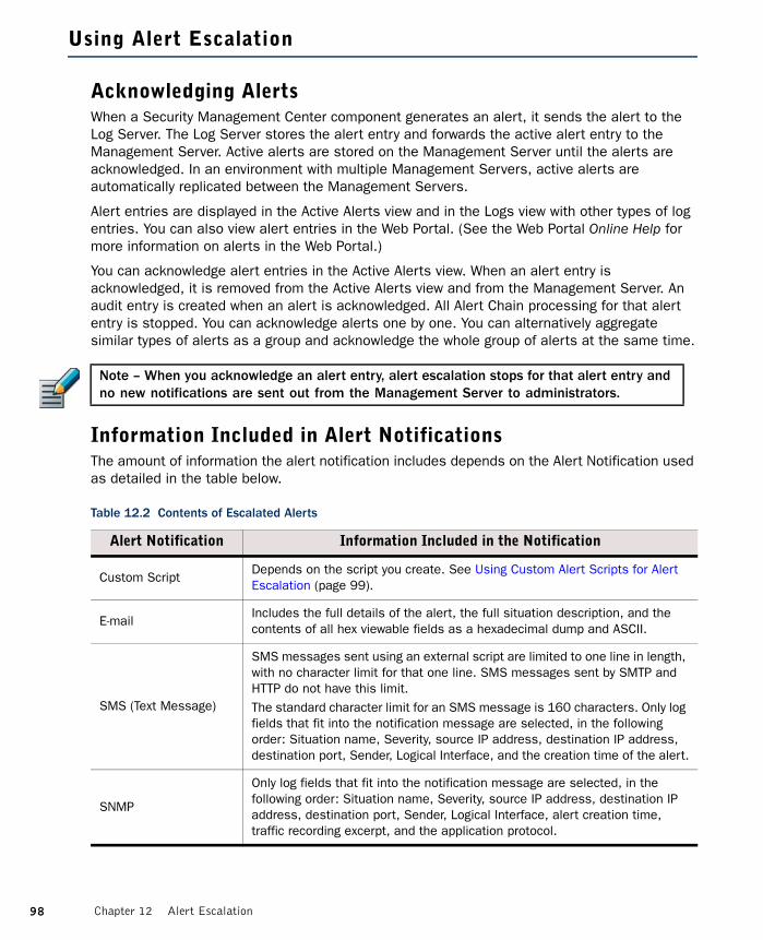
Using Alert Escalation
Acknowledging AlertsWhen a Security Management Center component generates an alert, it sends the alert to the Log Server. The Log Server stores the alert entry and forwards the active alert entry to the Management Server. Active alerts are stored on the Management Server until the alerts are acknowledged. In an environment with multiple Management Servers, active alerts are automatically replicated between the Management Servers.
Alert entries are displayed in the Active Alerts view and in the Logs view with other types of log entries. You can also view alert entries in the Web Portal. (See the Web Portal Online Help for more information on alerts in the Web Portal.)
You can acknowledge alert entries in the Active Alerts view. When an alert entry is acknowledged, it is removed from the Active Alerts view and from the Management Server. An audit entry is created when an alert is acknowledged. All Alert Chain processing for that alert entry is stopped. You can acknowledge alerts one by one. You can alternatively aggregate similar types of alerts as a group and acknowledge the whole group of alerts at the same time.
Information Included in Alert NotificationsThe amount of information the alert notification includes depends on the Alert Notification used as detailed in the table below.
Note – When you acknowledge an alert entry, alert escalation stops for that alert entry and no new notifications are sent out from the Management Server to administrators.
Table 12.2 Contents of Escalated Alerts
Alert Notification Information Included in the Notification
Custom ScriptDepends on the script you create. See Using Custom Alert Scripts for Alert Escalation (page 99).
E-mailIncludes the full details of the alert, the full situation description, and the contents of all hex viewable fields as a hexadecimal dump and ASCII.
SMS (Text Message)
SMS messages sent using an external script are limited to one line in length, with no character limit for that one line. SMS messages sent by SMTP and HTTP do not have this limit.The standard character limit for an SMS message is 160 characters. Only log fields that fit into the notification message are selected, in the following order: Situation name, Severity, source IP address, destination IP address, destination port, Sender, Logical Interface, and the creation time of the alert.
SNMP
Only log fields that fit into the notification message are selected, in the following order: Situation name, Severity, source IP address, destination IP address, destination port, Sender, Logical Interface, alert creation time, traffic recording excerpt, and the application protocol.
98 Chapter 12 Alert Escalation

Rule Order in Alert Policies and Alert ChainsThe system processes Alert Policies and Alert Chains from top down, so the order of the rules is important. In Alert Policies, rules must proceed from those with the most limited scope to those that are the most general. In Alert Chains, the order of the rules determines the order in which the alert notifications are sent.
Using Custom Alert Scripts for Alert EscalationTo send alert notifications using Custom Alert Scripts, you must define the Root Path on the Management Server where custom alert scripts are executed. The default location is <installation directory>/data/notification. All custom scripts must be stored in the same root path that is defined in the properties of the Management Server that controls the Shared Domain.
The example notification script notify.bat in Windows and notify.sh in Linux can be modified for your own use. In Linux, the sgadmin user needs read, write, and execute permissions in the script’s directory.
The alert information is given to the script as command arguments as described in the table below.
Table 12.3 Arguments Passed to the Custom Scripts
Argument Number Content Description
1 Alert ID The unique identifier for the alert.
2 Alert Name The name defined in the alert properties.
3 Alert Originator The IP address of the component that generated this alert.
4 Alert Date The date when the alert was originally generated.
5 Alert Message A short alert description.
6 Alert Severity
The Severity value of the alert from 1 to 10 where 1 is the least severe and 10 is the most severe. The numerical Severity value corresponds to the following Severity value in the generated alert:1= Info, 2-4=Low, 5-7=High, and 8-10=Critical.
7Alert Short Description
The contents of the Comment field in the alert properties.
8 Event ID IPS only: reference to the event ID that triggered the alert.
9Situation Description
Long description of the Situation that triggered the alert.
99Using Alert Escalation

Examples of Alert Escalation
The examples in this section illustrate some common uses for Alert Escalation and the general steps on how each scenario is configured.
Disabling All Alert Escalation for a Specific SituationThe administrators at company A notice that the system issues an alert every time someone mistypes their password when logging in using the Management Client. They decide that they do not want to receive alert notifications about failed logins because they have set up their IPS system to detect if there are several failed logins within a short period of time (which could indicate malicious activity).
The administrators:
1. Create a new Alert Chain and name it Auto-acknowledge.
2. Set the final action for the Auto-acknowledge Alert Chain to Acknowledge without adding any new rows.
3. Add the following new rule at the top of the Alert Policy:
4. Refresh the Alert Policy on the Shared Domain.
After this change, the alerts for failed logins are still generated and stored, but they do not trigger any alert notification and they are never shown in the Active Alerts view. For example, reports can still include information about failed login attempts to highlight excessive login failures.
Escalating Alerts Based on ResponsibilitiesCompany B has two sites, a branch office (BO) and a headquarters (HQ) site, which both have their own administrators. Both sites have a Firewall and a Log Server, and the shared Management Server is located at the HQ. Domains are not used, so all elements are in the Shared Domain.
For the most severe alert entries, the administrators decide to set up alert escalation as an SMS text message to the shared mobile phone each site has for the administrator on duty. If the administrator on duty at one site does not acknowledge the alert entry within 15 minutes, the alert notification is sent to the administrator on duty at the other site.
For less severe alert entries, the alerts are only escalated to the site where the alert entry is created. At first, the less severe notifications are sent only through a User Notification in the Management Client. After an hour, the alert notification is sent as an SMS text message to the shared mobile phone of the site where the alert entry is created.
Table 12.4 Alert Policy Rule Example
Sender Alert and Situation Chain
ANY“Management Server: Login Failed” Situation element
“Auto-acknowledge” Alert Chain
100 Chapter 12 Alert Escalation

The administrators:
1. Create new Alert Chains for high-severity and low-severity alert entries for both the HQ and the BO sites. There are four Alert Chains in total:•“HQ Important Alerts” contains the following rules:
•“HQ Minor Alerts” contains the following rules:
•The “BO Important Alerts” and “BO Minor Alerts” Alert Chains are the same as the HQ Alert Chains, but with the BO Administrators and a different phone number.
2. Create a new Alert Policy with the following rules:
3. Configure SMS Notification in the Management Server’s properties.
4. Install the new Alert Policy on the Shared Domain.
Table 12.5 “HQ Important Alerts” Alert Chain
Channel Destination Delay
SMS [Phone number for HQ shared mobile phone] 15 min
SMS [Phone number for BO shared mobile phone]
Table 12.6 “HQ Minor Alerts” Alert Chain
Channel Destination Delay
USER NOTIFICATIONHQ Administrator AHQ Administrator B[etc.]
60 min
SMS [Phone number for HQ shared mobile phone]
Table 12.7 Example Alert Policy
Sender Alert and Situation Severity Chain
HQ FirewallHQ Log ServerManagement Server
ANY High ... Critical HQ Important Alerts
HQ FirewallHQ Log ServerManagement Server
ANY Info ... Low HQ Minor Alerts
BO FirewallBO Log Server
ANY High ... Critical BO Important Alerts
BO FirewallBO Log Server
ANY Info ... Low BO Minor Alerts
101Examples of Alert Escalation

102 Chapter 12 Alert Escalation
CHAPTER 13
REPORTS
Reports are summaries of logs and statistics that allow you to combine large amounts of data into an easily viewable form.
The following sections are included:
Overview of Reports (page 104)Configuration of Reports (page 104)Using Reporting Tools (page 108)Example Report (page 111)
103
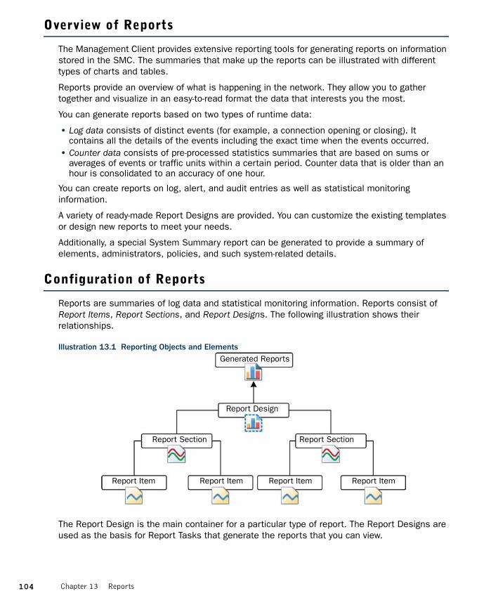
Overview of Reports
The Management Client provides extensive reporting tools for generating reports on information stored in the SMC. The summaries that make up the reports can be illustrated with different types of charts and tables.
Reports provide an overview of what is happening in the network. They allow you to gather together and visualize in an easy-to-read format the data that interests you the most.
You can generate reports based on two types of runtime data:
• Log data consists of distinct events (for example, a connection opening or closing). It contains all the details of the events including the exact time when the events occurred.
• Counter data consists of pre-processed statistics summaries that are based on sums or averages of events or traffic units within a certain period. Counter data that is older than an hour is consolidated to an accuracy of one hour.
You can create reports on log, alert, and audit entries as well as statistical monitoring information.
A variety of ready-made Report Designs are provided. You can customize the existing templates or design new reports to meet your needs.
Additionally, a special System Summary report can be generated to provide a summary of elements, administrators, policies, and such system-related details.
Configuration of Reports
Reports are summaries of log data and statistical monitoring information. Reports consist of Report Items, Report Sections, and Report Designs. The following illustration shows their relationships.
Illustration 13.1 Reporting Objects and Elements
The Report Design is the main container for a particular type of report. The Report Designs are used as the basis for Report Tasks that generate the reports that you can view.
Report Design
Report Item
Generated Reports
Report Section Report Section
Report Item Report Item Report Item
104 Chapter 13 Reports
The Report Design consists of one or more Report Sections. A Report Section defines parameters for all items within it. It mainly defines how the information is displayed, such as the type of chart and the number of top items shown. Each Report Section in the Report Design creates a separate chart and/or a table in the generated report.
Each Report Section contains one or more Report Items, which each represent a way to summarize the data. For example, a Report Item may summarize the total number of connections counted for the period between the start and end times defined for the task that generates the report. Each item adds specific information to the chart or table that the Report Section generates. For example, if the Report Section displays a curve chart and contains items for total traffic volume, sent traffic volume, and received traffic volume, the generated report shows the three items as three separate lines on the same chart.
Configuration WorkflowThe following sections provide an overview of the configuration tasks. Detailed step-by-step instructions can be found in the Management Client Online Help and the McAfee SMC Administrator’s Guide.
Task 1: Create a New Report DesignThere are several ways to create new Report Designs. Although you can start by defining a new empty Report Design, it is often easier to use one of the predefined Report Designs as a template. The comments in the properties of predefined Report Designs and Sections explain their general purpose.
The Report Design properties specify, for example, the time period for the report. You can define a period comparison for the Report Design. This allows you to compare values between two identical time periods. For example, if the time period is one week, you can compare the results for this week to the results from the previous week.
Task 2: Customize Report Sections and ItemsYou can add predefined Report Sections to your Report Design and then modify their contents and properties according to your needs.
A Report Section represents a collection of Report Items in reports. Each Report Section adds a separate summary (chart and/or table) to the report. Depending on the summary type, the summary can be presented in one or more of the following ways:
• bar chart • stacked bar chart• curve chart• stacked curve chart• pie chart• geolocation map• table.
105Configuration of Reports

The available types of Report Section summaries are explained in Table 13.1.
A Report Item represents a value that you want to count in log data or statistical monitoring information (for example, allowed traffic in bits or the number of allowed connections).
Table 13.1 Summary Types
Summary Type Description Visualization
Progress
Illustrates how events are spread out within the reporting period. This summary type is useful for finding trends in the data.Example: a line chart showing the volume of traffic during a 24-hour period.
A bar chart, stacked bar chart, curve chart, or stacked curve chart.
Top Rate
Illustrates events with the highest occurrences. This summary type is useful for highlighting the most common values in the data.Example: a bar chart showing the number of connections to the five IP addresses that have received the most connections yesterday.The first Report Item in a top rate summary section must have a sorting criteria “by X” (for example, allowed connections by source IP address), because the sorting criteria is applied to all the items of the section for ranking the top rates.
A bar chart, a pie chart or a geolocation map. A bar chart is more suitable for displaying a large number of top rates, whereas a pie chart is better at illustrating the relative proportions. A geolocation map shows the distribution of events according to physical location.
Drill-Down Top Rate
First, creates a top rate summary of events. Then, sections below use the data in the top rate summary to produce further charts and tables.Example: a drill-down section that shows the top ten IP addresses in terms of traffic volume, followed by a further progress summary that shows in detail how the combined traffic from those IP addresses is spread throughout the week.Drill-down sections must be at the end of the Report Design. All other sections that you place below a drill-down top rate summary section in the Report Design become part of the drill-down top rate summary, except other drill-down sections (and the sections they include).
A bar chart, a pie chart or a geolocation map.
Summary Table
A simple table for displaying the exact event counts. This summary type is useful for providing data for further processing, for example, in a spreadsheet application.
A table.
System Information
Summarizes current configuration information in the Management Server’s internal database.Example: a listing of all engines with the software versions, names of the currently installed policies, and the latest policy upload times.
A table.
106 Chapter 13 Reports

The data for the Report Items is generated in the following ways:
• A simple count of how many log entries have a certain value within the reporting period. For example, the Allowed Connections Report Item counts the log entries that have the value Allowed in the Action field. This is how the results for most Report Items are summed.
• A count of how many log entries have a certain value within the reporting period grouped by the additional “by X” criteria. For example, Allowed connections by source IP address presents a chart for an adjustable number of IP addresses that have the most allowed connections within the reporting period.
• Sums or averages of traffic volumes in log entries for Report Items of the “traffic” type (for example, Allowed traffic). The data for “traffic” items is generated by Access rules that have the accounting option enabled in the Firewall Policy. Interface statistics often provide more accurate total volumes, since accounting (and logging in general) is not usually active for all rules.
• Values stored in the Management Server’s database for System Information items. The statistical data is pre-summarized, so it is not as detailed as the monitoring statistics displayed in the System Status view, and cannot be filtered in detail like the log data (see Filtering Data in Reporting (page 108)).
Task 3: Generate a ReportWhen you start a Report Operation, the Management Server sends the task to all Log Servers that are not specifically excluded for processing. The task’s progress and possible errors are shown next to the task under the selected Report Design. Each Log Server processes the task and returns the summary data for each Report Section. The Management Server merges the data from the Log Servers into one report. If one of the selected Log Servers cannot be contacted for any reason, the execution of the task is delayed until the Log Server becomes available.
107Configuration of Reports

Using Reporting Tools
Filtering Data in ReportingThe Report Items define some general criteria for selecting data. For example, you can produce a report of connections by source IP address. This is a good way to get an overview, but in many cases, you want more specific information. Filters are the main tool for increasing the granularity of reports.
For example, a very general item such as the total number of logged connections can be made much more specific by applying a filter that matches a single pair of source and destination IP addresses (to count connections between just those two specific hosts).
Only log-based raw data is suitable for log filters. Counter Statistics Data items use pre-counted statistical data instead of logs, so most log data filters cannot be used with Counter Statistics Report Items. Filters that specify the sender (the component that generated the statistics) can be used with Counter Statistics items, and may be useful in Reports.
You can define a filter at one or more of the following levels:
1. Report Task: applies to the single report produced by a particular task, or to all reports produced by a task that is scheduled to run regularly.
2. Report Design: applies to all reports produced using the Report Design.
3. Report Section: applies to all items included in the section.
4. Report Item: applies to that specific item only.
If filters are applied at several of these levels, all filters are applied and the log entries are filtered top-down in the order listed. Each filtering stage completely excludes non-matching log entries for the stage in which the filter is applied and all further stages. For example, if you select a filter for TCP destination port 80 for a Report Section, all items in that section only process information in log entries that mention TCP destination port 80.
Using Domains with ReportsIf there are Domains configured, the reports are Domain-specific. While logged in to a Domain, you can only create reports concerning the components that belong to that Domain. If you are allowed to log in to the Shared Domain and have unrestricted permissions, you can create Reports concerning components in any Domains. The Reports created in the Shared Domain are visible to administrators in all other Domains. If the reports contain sensitive data that should not be displayed to all the administrators in all Domains, create the reports in a specific Domain. See Domains (page 65) for more information.
Using the System ReportWhile other reports are based on logs and statistics, the System Report is based on information collected from the Management Server’s configuration database and audit logs. It includes such details as administrator and Web Portal user activity, information on account settings, configuration of and changes to the Firewall and IPS engines, and the configuration of the Management Server. The System Report is intended to help you provide the required data for
108 Chapter 13 Reports

auditing in compliance with regulations, such as the Payment Card Industry (PCI) Data Security Standard. The System Report is generated, exported, and edited in the same way as other types of reports: the only difference is the content of the report.
Exporting ReportsYou can export generated reports as PDF or HTML files, or tab-delimited text files. PDF exports allow you to use your own background template.
Exporting PDF and HTML reports can be done manually for previously generated reports or automatically as part of a report generating operation. Exporting tab-delimited text files can only be done automatically as part of a Report Task.
Automatically exported files can be automatically sent out as e-mail and/or saved in the <installation directory>/data/reports/files/report_design/ directory on the Management Server. The report files are named according to the report’s time range as follows: startdate_starttime_enddate_endtime_N.pdf (or .txt), where N is a sequential number (starting from 1) that identifies files with the same time range. For example, 20100423_100000_20100424_180000_1.txt is the first text report generated for the time range from 23 Apr 2010 10:00:00 to 24 Apr 2010 18:00:00.
Tab-Delimited Text Report FilesTab-delimited text files are designed to be used for further processing. The tab-delimited text files contain the statistics in tabulated tables. The Tab characters and the operating environment-specific line endings delimit the text.
Table 13.2 Structure of a Tab-Delimited Text Report File
Line No. File Content Description
1<Report Title>, <Start Time> - <End Time>
Start and End Time define the reporting period in format YYYY/MM/DD hh:mm:ss.
2 <empty line>
3<Section Content for each section>
Each section of the report follows the format described below.
Line No. Section Content Description
1<Section Name>[; <Section Comment>]
Optional Section Comment with a leading semi-colon (;) may follow the Section Name.
2 <empty line>
3 <Section Data> | “No data”Section Data follows the format described below. If the section contains no data, the text “No data” is displayed instead.
Section’s last line
<empty line>
109Using Reporting Tools

Post-Processing Report FilesYou can customize reports by post-processing them as part of the Report Task. Post-processing runs the <installation directory>/data/reports/bin/sgPostProcessReport script on the Management Server, and passes command arguments to the script. Table 13.3 explains the possible command arguments.
The script needs to parse the values from the command arguments to use the values for post-processing. Only parameters that have a defined value are forwarded to the post-processing script.
Line No. Section Data Content Description
1 <Table Heading>Tab delimited column labels. Some columns may not have a label, and labels may be padded with trailing spaces.
2 <empty line>
3 <Table rows>Tab delimited values. Value in any given column can be empty. The column values are not padded.
Section data’s last line
<empty line>
Table 13.3 Command Arguments for Post-Processing Reports
Command Argument Explanation
-creation_time YYYY/MM/DD hh:mm:ss
The report creation time.
-filter_categ name The category assigned to the task filter.
-filter_name filter The name of the filter assigned to the task.
-html_file filename The filename of a report exported as HTML.
-pdf_file filename The filename of a report exported as PDF.
-period_begin YYYY/MM/DD hh:mm:ss
The begin time of the reporting period.
-period_end YYYY/MM/DD hh:mm:ss
The end time of the reporting period.
-report_categ name A category assigned to the report (and to the report file).
-report_file_title title The title of the report file.
-report_name name The name of the report.
-text_file filename The filename of a report exported as plain text.
Table 13.2 Structure of a Tab-Delimited Text Report File (Continued)
110 Chapter 13 Reports

When a parameter has multiple values, each of the values is forwarded as a separate command argument. For example, when the report has the two categories “Example Corporation” and “weekly report”, these values are forwarded to the script as “-report_categ Example Corporation” and “-report_categ weekly report”.
Example Report
The example in this section illustrates a common use for reports and general steps on how the scenario in question is configured.
Pinpointing a Disruptive Internal UserAdministrators at Company A notice that downloads have gone up dramatically over the past week. They suspect that there may be an individual user that is excessively downloading files from the Internet. To confirm their suspicions, the Administrators decide to run a report that shows them who has used most bandwidth in the network.
The administrators:
1. Activate Log Accounting Information for each rule that allows connections from internal hosts to the Internet (incoming connections to internal workstations are not allowed) and install the policy.
2. Wait for a full workday for the logs with accounting information to be generated.
3. Create a filter that matches the IP address space of regular workstations as the source address and any external IP addresses as the destination address.
4. Create a new Report Design based on the Firewall Daily summary and attach the filter created in the previous step to the Report Design.
5. Increase the “Top Limit” value for the section “Traffic by src. IP” to see more results.
6. Generate a report for the previous day to check the traffic volumes for the top hosts.
111Example Report

112 Chapter 13 Reports
CHAPTER 14
INCIDENT CASES
The Incident Case element is a tool that helps you record investigations of suspicious activity.
The following sections are included:
Overview of Incident Cases (page 114)Configuration of Incident Cases (page 114)Examples of Incident Cases (page 116)
113
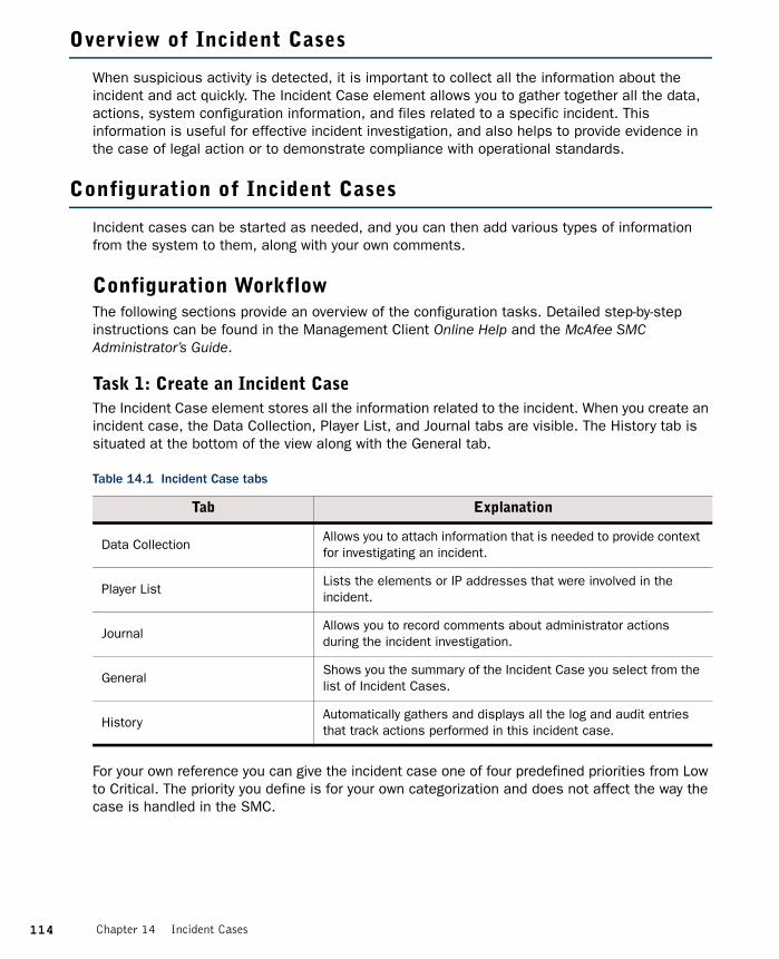
Overview of Incident Cases
When suspicious activity is detected, it is important to collect all the information about the incident and act quickly. The Incident Case element allows you to gather together all the data, actions, system configuration information, and files related to a specific incident. This information is useful for effective incident investigation, and also helps to provide evidence in the case of legal action or to demonstrate compliance with operational standards.
Configuration of Incident Cases
Incident cases can be started as needed, and you can then add various types of information from the system to them, along with your own comments.
Configuration WorkflowThe following sections provide an overview of the configuration tasks. Detailed step-by-step instructions can be found in the Management Client Online Help and the McAfee SMC Administrator’s Guide.
Task 1: Create an Incident CaseThe Incident Case element stores all the information related to the incident. When you create an incident case, the Data Collection, Player List, and Journal tabs are visible. The History tab is situated at the bottom of the view along with the General tab.
For your own reference you can give the incident case one of four predefined priorities from Low to Critical. The priority you define is for your own categorization and does not affect the way the case is handled in the SMC.
Table 14.1 Incident Case tabs
Tab Explanation
Data CollectionAllows you to attach information that is needed to provide context for investigating an incident.
Player ListLists the elements or IP addresses that were involved in the incident.
JournalAllows you to record comments about administrator actions during the incident investigation.
GeneralShows you the summary of the Incident Case you select from the list of Incident Cases.
HistoryAutomatically gathers and displays all the log and audit entries that track actions performed in this incident case.
114 Chapter 14 Incident Cases

Task 2: Set the Management Client to Incident Handling ModeYou can set your Management Client to work in the context of solving a particular Incident Case. When you do this, the Management Client attaches the selected Incident Case in the audit trail that the system generates of your actions. The audited actions can then be easily viewed through the history of the selected Incident Case.
Task 3: Attach DataThe following types of data can be attached to the Incident Case:
Task 4: Attach PlayersA player is any element or IP address that was involved in the incident. Attaching players to an incident case creates a reference to an element.
Task 5: Write Journal EntriesThe journal allows administrators to keep a record of what actions they have performed and why they have performed them while investigating the incident. It is especially useful when more than one administrator is investigating the same incident simultaneously.
Once a journal entry is saved, it cannot be edited. This provides an audit for incident management (for example, to be used as evidence in court).
Task 6: Close the Incident CaseWhen the investigation is finished, you can close the incident case. The incident case stays in the system, but its state is marked as closed. It is a good idea to keep resolved incident cases as a record of past incidents or for future reference in dealing with new incidents.
Table 14.2 Data Collection
Data Item Explanation
LogsLog, alert, and audit entries from Firewall or IPS engines and Log and Management Servers.
Policy SnapshotA record of record of a configuration stored in the upload history. Policy Snapshots help to establish which policies were in place at the time of the incident.
MemoA simple text file for attaching excerpts of text, for example, by copying and pasting from e-mail, IRC or instant messaging.
FileAny type of file. For example, saved reports, text files, saved e-mail messages, packet capture files, or screenshot images.
115Configuration of Incident Cases

Examples of Incident Cases
There are many ways an administrator can become aware of suspicious activity in the system. However, the most likely way is by noticing something unusual in the logs or audit entries, or being warned about a potential problem in an alert. Once a suspicious event is detected, the workflow generally follows one of these scenarios:
Investigation by More Than One Administrator1. An administrator creates a new incident case.
2. The administrator delegates work to other administrators.
3. Each administrator collects data and players, and attaches them to the incident case.
4. An administrator reacts to contain the incident, for example, by stopping an engine or changing a Firewall policy.
5. An administrator may try to eradicate the problem, for example, by installing software patches or updating anti-virus programs.•The administrator can write a new comment in the incident journal to inform the other
administrators about what has been done.6. When the problem is resolved, the administrator closes the incident case.
Investigation of a False Positive1. The administrator creates a new incident case.
2. While collecting data, the administrator discovers that the suspicious event was not a real problem.
3. The administrator marks the incident case as a false positive.
Investigation of Suspected Backdoor TrafficThe administrator receives an IPS alert that there is active two-way backdoor traffic between a server in the organization's internal network and an unknown host in the Internet. The administrator then:
1. Opens a new incident case to help manage this incident.
2. Searches for previous logs from the Firewall and IPS engines to identify the vulnerability that allowed the server to be compromised.
3. Attaches the relevant logs to the incident case.
4. Re-installs the server, and installs patches to prevent the same vulnerability from being exploited again.
5. Closes the incident case.
116 Chapter 14 Incident Cases

117
APPENDICES
In this section:
Default Communication Ports - 119
Command Line Tools - 127
Predefined Aliases - 149
Log Fields - 153
Schema Updates for External LDAP Servers - 201
Glossary - 203
Index - 233

118

APPENDIX A
DEFAULT COMMUNICATION PORTS
This chapter lists the default ports used in connections between SMC components and the default ports SMC components use with external components.
The following sections are included:
Security Management Center Ports (page 120)Security Engine Ports (page 123)
119

Security Management Center Ports
The illustrations below present an overview to the most important default ports used in communications between the Security Management Center (SMC) components and from the SMC to external services. See the table below for a complete list of default ports.
Illustration A.1 Destination Ports for Basic Communications Within SMC
Illustration A.2 Default Destination Ports for Optional SMC Components and Features
TCP:8914-8918
Log Server Management Server
TCP:8902-8913
3021 (Log Server Certificate Request)
3023
Management Client
Management Server
McAfee’s Update Service
External LDAP Server
External RADIUS Server
TCP:443
TCP:389
UDP:1812
Additional Management Server
Log Server
Web Portal Server
TCP:8902-8913,
8916, 8917, 3023+ 3021
(Certificate Request)
TCP:302089168917
TCP:89038907
TCP:8902-8913
Monitored Third-Party
Components
UDP:161
TCP, UDP:162/5162514/5514Win/Linux)
TCP: 8925 - 8929
Authentication Server
TCP:8907+ 3021 (Certificate Request)
TCP:3020
120 Appendix A Default Communication Ports
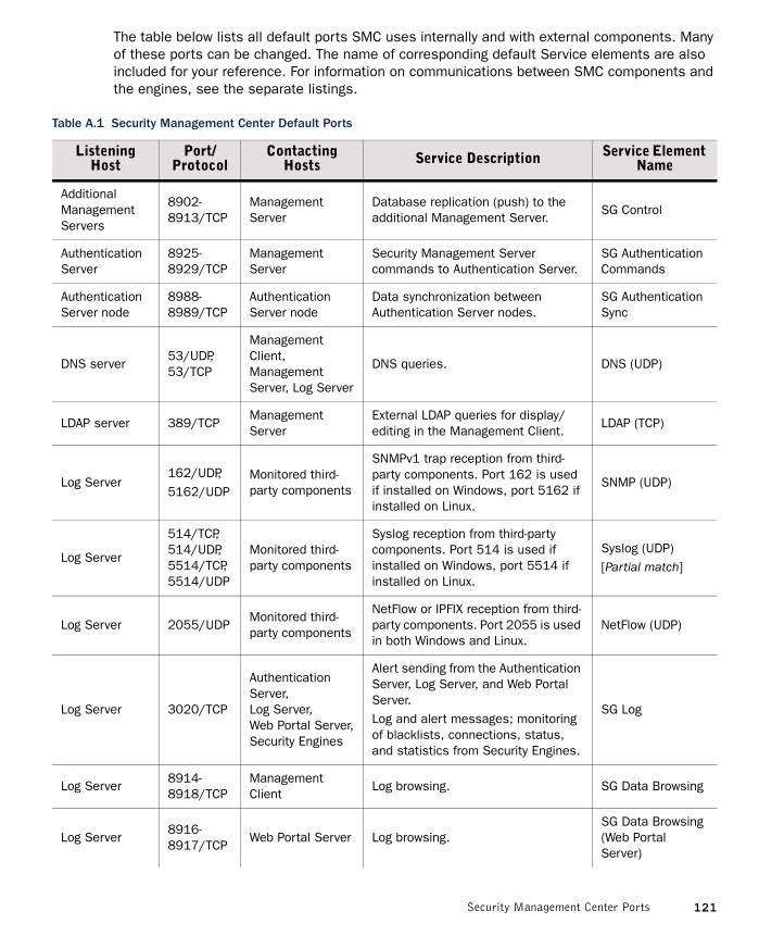
The table below lists all default ports SMC uses internally and with external components. Many of these ports can be changed. The name of corresponding default Service elements are also included for your reference. For information on communications between SMC components and the engines, see the separate listings.
Table A.1 Security Management Center Default Ports
Listening Host
Port/Protocol
Contacting Hosts Service Description Service Element
Name
Additional Management Servers
8902- 8913/TCP
Management Server
Database replication (push) to the additional Management Server.
SG Control
Authentication Server
8925-8929/TCP
Management Server
Security Management Server commands to Authentication Server.
SG Authentication Commands
Authentication Server node
8988-8989/TCP
Authentication Server node
Data synchronization between Authentication Server nodes.
SG Authentication Sync
DNS server53/UDP,53/TCP
Management Client, Management Server, Log Server
DNS queries. DNS (UDP)
LDAP server 389/TCPManagement Server
External LDAP queries for display/editing in the Management Client.
LDAP (TCP)
Log Server162/UDP,5162/UDP
Monitored third-party components
SNMPv1 trap reception from third-party components. Port 162 is used if installed on Windows, port 5162 if installed on Linux.
SNMP (UDP)
Log Server
514/TCP, 514/UDP, 5514/TCP, 5514/UDP
Monitored third-party components
Syslog reception from third-party components. Port 514 is used if installed on Windows, port 5514 if installed on Linux.
Syslog (UDP)[Partial match]
Log Server 2055/UDPMonitored third-party components
NetFlow or IPFIX reception from third-party components. Port 2055 is used in both Windows and Linux.
NetFlow (UDP)
Log Server 3020/TCP
Authentication Server, Log Server,Web Portal Server,Security Engines
Alert sending from the Authentication Server, Log Server, and Web Portal Server.Log and alert messages; monitoring of blacklists, connections, status, and statistics from Security Engines.
SG Log
Log Server8914-8918/TCP
Management Client
Log browsing. SG Data Browsing
Log Server8916-8917/TCP
Web Portal Server Log browsing.SG Data Browsing (Web Portal Server)
121Security Management Center Ports

Management Server
3021/TCPLog Server, Web Portal Server
System communications certificate request/renewal.
SG Log Initial Contact
Management Server
8902-8913/TCP
Management Client, Log Server, Web Portal Server
Monitoring and control connections. SG Control
Management Server
3023/TCP
Additional Management Servers, Log Server, Web Portal Server
Log Server and Web Portal Server status monitoring.Status information from an additional Management Server to the active Management Server.
SG Status Monitoring
Management Server
8903, 8907/TCP
Additional Management Servers
Database replication (pull) to the additional Management Server.
SG Control
Management Server
8907/TCPAuthentication Server
Status monitoring. SG Control
Monitored third-party components
161/UDP Log ServerSNMP status probing to external IP addresses.
SNMP (UDP)
RADIUS server 1812/UDPManagement Server
RADIUS authentication requests for administrator logins. The default ports can be modified in the properties of the RADIUS Server element.
RADIUS (Authentication)
SMC servers 443/TCPManagement Server
Update packages, engine upgrades, and licenses from update-pool.stonesoft.com and smc-pool.stonesoft.com.
HTTPS
Syslog server514/UDP, 5514/UDP
Log Server
Log data forwarding to syslog servers. The default ports can be modified in the LogServerConfiguration.txt file.
Syslog (UDP)[Partial match]
Third-party components
2055/UDP Log ServerNetFlow or IPFIX forwarding to third-party components. Port 2055 is used in both Windows and Linux.
NetFlow (UDP)
Table A.1 Security Management Center Default Ports (Continued)
Listening Host
Port/Protocol
Contacting Hosts Service Description Service Element
Name
122 Appendix A Default Communication Ports

Security Engine Ports
The illustrations below present an overview to the most important default ports used in communications between Security Engines and the SMC and between clustered Security Engine nodes. See the table below for a complete list of default ports for the engines.
Illustration A.3 Destination Ports for Basic Security Engine Communications
Illustration A.4 Default Destination Ports for Security Engine Service Communications
Note – Master Engines use the same default ports as clustered Security Engines. Virtual Security Engines do not communicate directly with other system components.
Other Node(s) in the ClusterLog Server Security Engine /
Master Engine
Management Server
TCP:
3020TCP:636
495049878888
Or none*TCP:30213023
8906*
*Single engines with “Node-initiated Contact to Management Server” selected.
TCP:300230033010
UDP:30003001
Multicast(Heartbeat interfaces)
Server Pool*
DNS Server
LDAP Server* RADIUS Server* TACACS+ Server*
DHCP Server* SNMP Server
RPCServer*
Security Engine /Master Engine
VPN Clients*
VPNGateways*UDP:
50027464500
UDP:68
UDP:161UDP:
67UDP:162
TCP, UDP:111
UDP:7777
TCP:389636
UDP:18121645
TCP, UDP:53
TCP:49
UDP:500
4500 UDP:500
27464500
User Agent*
TCP:16661
* Engines in the Firewall/VPN role.
123Security Engine Ports

The table below lists all default ports the Security Engines use internally and with external components. Many of these ports can be changed. The name of corresponding default Service elements are also included for your reference.
Table A.2 Security Engine and Master Engine Default Ports
Listening Host Port/Protocol Contacting
Hosts Service Description Service Element Name
Anti-virus signature server
80/TCP Firewall Anti-virus signature update service. HTTP
Authentication Server
8925-8929/TCP
Firewall, Master Engine
User directory and authentication services.
LDAP (TCP), RADIUS (Authentication)
BrightCloud Server
2316/TCPFirewall, Layer 2 Firewall, IPS, Master Engine
BrightCloud URL filtering update service.
BrightCloud update
DHCP server 67/UDP FirewallRelayed DHCP requests and requests from a firewall that uses dynamic IP address.
BOOTPS (UDP)
DNS server53/UDP, 53/TCP
Firewall, Master Engine
Dynamic DNS updates. DNS (TCP)
Firewall 67/UDP Any DHCP relay on firewall engine. BOOTPS (UDP)
Firewall 68/UDP DHCP server Replies to DHCP requests. BOOTPC (UDP)
Firewall, Master Engine
500/UDPVPN clients, VPN gateways
VPN negotiations, VPN traffic. ISAKMP (UDP)
Firewall, Master Engine
636/TCPManagement Server
Internal user database replication. LDAPS (TCP)
Firewall, Master Engine
2543/TCP AnyUser authentication (Telnet) for Access rules.
SG User Authentication
Firewall 2746/UDPMcAfee VPN gateways
UDP encapsulated VPN traffic (engine versions 5.1 and lower).
SG UDP Encapsulation
Firewall, Master Engine
4500/UDPVPN client, VPN gateways
VPN traffic using NAT-traversal. NAT-T
Firewall Cluster Node, Master Engine cluster node
3000-3001/UDP3002-3003, 3010/TCP
Firewall Cluster Node, Master Engine cluster node
Heartbeat and state synchronization between clustered Firewalls.
SG State Sync (Multicast), SG State Sync (Unicast), SG Data Sync
Firewall, Layer 2 Firewall, IPS, Master Engine
4950/TCPManagement Server
Remote upgrade.SG Remote Upgrade
124 Appendix A Default Communication Ports

Firewall, Layer 2 Firewall, IPS, Master Engine
4987/TCPManagement Server
Management Server commands and policy upload.
SG Commands
Firewall, Layer 2 Firewall, IPS
8888/TCPManagement Server
Connection monitoring for engine versions 5.1 and lower.
SG Legacy Monitoring
Firewall, Layer 2 Firewall, IPS, Master Engine
15000/TCPManagement Server, Log Server
Blacklist entries. SG Blacklisting
Firewall, Layer 2 Firewall, IPS, Master Engine
161/UDP SNMP server SNMP monitoring. SNMP (UDP)
IPS Cluster Node
3000-3001/UDP3002-3003, 3010/TCP
IPS Cluster Node
Heartbeat and state synchronization between clustered IPS engines.
SG State Sync (Multicast), SG State Sync (Unicast), SG Data Sync
LDAP server 389/TCPFirewall, Master Engine
External LDAP queries, including StartTLS connections.
LDAP (TCP)
Layer 2 Firewall Cluster Node
3000-3001/UDP3002-3003, 3010/TCP
Layer 2 Firewall Cluster Node
Heartbeat and state synchronization between clustered Layer 2 Firewalls.
SG State Sync (Multicast), SG State Sync (Unicast), SG Data Sync
Log Server 3020/TCPFirewall, Layer 2 Firewall, IPS, Master Engine
Log and alert messages; monitoring of blacklists, connections, status, and statistics.
SG Log
Management Server
3021/TCPFirewall, Layer 2 Firewall, IPS, Master Engine
System communications certificate request/renewal (initial contact).
SG Initial Contact
Management Server
3023/TCPFirewall, Layer 2 Firewall, IPS, Master Engine
Monitoring (status) connection.SG Status Monitoring
Management Server
8906/TCPFirewall, Layer 2 Firewall, IPS
Management connection for single engines with “Node-Initiated Contact to Management Server” selected.
SG Dynamic Control
RADIUS server1812, 1645/UDP
Firewall, Master Engine
RADIUS authentication requests.RADIUS (Authentication), RADIUS (Old)
Table A.2 Security Engine and Master Engine Default Ports (Continued)
Listening Host Port/Protocol Contacting
Hosts Service Description Service Element Name
125Security Engine Ports

RPC server111/UDP, 111/TCP
Firewall, Master Engine
RPC number resolve.SUNRPC (UDP), Sun RPC (TCP)
Server Pool Monitoring Agents
7777/UDPFirewall, Master Engine
Polls to the servers’ Server Pool Monitoring Agents for availability and load information.
SG Server Pool Monitoring
SNMP server 162/UDPFirewall, Layer 2 Firewall, IPS, Master Engine
SNMP traps from the engine. SNMP Trap (UDP)
TACACS+ server 49/TCPFirewall, Master Engine
TACACS+ authentication requests. TACACS (TCP)
User Agent 16661/TCPFirewall, Master Engine
Queries for matching Users and User Groups with IP addresses.
SG Engine to User Agent
VPN gateways
500/UDP, 2746/UDP (McAfee gateways only), or 4500 UDP.
Firewall, Master Engine
VPN traffic. Ports 2746 and 4500 may be used depending on encapsulation options.
ISAKMP (UDP)
Table A.2 Security Engine and Master Engine Default Ports (Continued)
Listening Host Port/Protocol Contacting
Hosts Service Description Service Element Name
126 Appendix A Default Communication Ports

APPENDIX B
COMMAND LINE TOOLS
This appendix describes the command line tools for McAfee Security Management Center and the NGFW engines.
The following sections are included:
Security Management Center Commands (page 128)NGFW Engine Commands (page 139)Server Pool Monitoring Agent Commands (page 147)
Note – Using the Management Client is the recommended configuration method, as most of the same tasks can be done through it.
127

Security Management Center Commands
Security Management Center commands include commands for the Management Server, Log Server, Web Portal Server, and Authentication Server. Most of the commands are found in the <installation directory>/bin/ directory. In Windows, the command line tools are *.bat script files. In Linux, the files are *.sh scripts.
Commands that require parameters must be run through the command line (cmd.exe in Windows). Commands that do not require parameters can alternatively be run through a graphical user interface, and may be added as shortcuts during installation.
Note – If you installed the Management Server in the C:\Program Files\McAfee\Security Management Center directory in Windows, some of the program data is stored in the C:\ProgramData\McAfee\Security Management Center directory. Command line tools may be found in the C:\Program Files\McAfee\Security Management Center\bin and/or the C:\ProgramData\McAfee\Security Management Center\bin directory.
Caution – login and password parameters are optional. Giving them as Command Line parameters may pose a security vulnerability. Do not enter login and password information unless explicitly prompted to do so by a Command Line tool.
Table B.1 Security Management Center Command Line Tools
Command Description
sgArchiveExport
[host=<Management Server Address[\Domain]>] [login=<login name>] [pass=<password>] [format=<exporter format: CSV or XML>] i=<input files and/or directories>[o=<output file name>] [f=<filter file name>] [e=<filter expression>] [-h | -help | -?] [-v]
Displays or exports logs from archive. This command is only available on the Log Server. The operation checks privileges for the supplied administrator account from the Management Server to prevent unauthorized access to the logs.Enclose details in double quotes if they contain spaces.
128 Appendix B Command Line Tools

sgArchiveExport
(continued)
Host specifies the address of the Management Server. If the parameter is not defined, the loopback address (localhost) is used.login defines the username for the account that is used for this operation. If this parameter is not defined, the username root is used.pass defines the password for the user account.format defines the file format for the output file. If this parameter is not defined, the XML format is used.i defines the source from which the logs will be exported. Can be a folder or a file. The processing recurses into subfolders.o defines the destination file where the logs will be exported. If this parameter is not defined, the output is displayed on screen.f defines a file that contains the filtering criteria you want to use for filtering the log data. You can export log filters individually in the Management Client through Tools→Save for Command Line Tools in the filter’s right-click menu.e allows you to type in a filter expression manually (using the same syntax as exported filter files).-h, -help, or -? displays information on using the script.-v displays verbose output on the command execution.Example (exports logs from one full day to a file using a filter):sgArchiveExport login=admin pass=abc123i=c:/mcafee/security_management_center/data/archive/firewall/year2011/month12/./sgB.day01/ f=c:/mcafee/security_management_center/export/MyExportedFilter.flp format=CSV o=MyExportedLogs.csv
sgBackupAuthSrv
[pwd=<password>][path=<destpath>][nodiskcheck][comment=<comment>][-h | --help]
Creates a backup of Authentication Server user information. The backup file is stored in the <installation directory>/backups/ directory. Backing up the Authentication only backs up Users, not the configuration of the Authentication Server. The Authentication Server configuration is included in the Management Server backup.pwd enables encryption.path defines the destination path.nodiskcheck ignores free disk check before creating the backup.comment allows you to enter a comment for the backup. The maximum length of a comment is 60 characters.-h or --help displays information on using the script.Also see sgRestoreAuthBackup.
Table B.1 Security Management Center Command Line Tools (Continued)
Command Description
129Security Management Center Commands

sgBackupLogSrv
[pwd=<password>][path=<destpath>][nodiskcheck][comment=<comment>][nofsstorage][-h | --help]
Creates a backup of Log Server configuration data. The backup file is stored in the <installation directory>/backups/ directory. Twice the size of log database is required on the destination drive. Otherwise, the operation fails.pwd entering a password enables encryption.path defines the destination path.nodiskcheck ignores free disk check before creating the backup.comment allows you to enter a comment for the backup. The maximum length of a comment is 60 characters.nofsstorage creates a backup only of the log server configuration without the log data.-h or --help displays information on using the script.Also see sgRestoreLogBackup.
sgBackupMgtSrv
[pwd=<password>][path=<destpath>][nodiskcheck][comment=<comment>][-h | --help]
Creates a complete backup of the Management Server (including both the local configuration and the stored information in the configuration database). The backup file is stored in the <installation directory>/backups/ directory. Twice the size of the Management Server database is required on the destination drive. Otherwise, the operation fails.pwd entering a password enables encryption.path defines the destination path.nodiskcheck ignores free disk check before creating the backup.comment allows you to enter a comment for the backup. The maximum length of a comment is 60 characters.-h or --help displays information on using the script.Also see sgRestoreMgtBackup and sgRecoverMgtDatabase.
sgCertifyAuthSrv
Contacts the Management Server and creates a new certificate for the Authentication Server to allow secure communications with other SMC components. Renewing an existing certificate does not require changing the configuration of any other SMC components.
Table B.1 Security Management Center Command Line Tools (Continued)
Command Description
130 Appendix B Command Line Tools

sgCertifyLogSrv[host=<Management Server Address[\Domain]>]
Contacts the Management Server and creates a new certificate for the Log Server to allow secure communications with other SMC components. Renewing an existing certificate does not require changing the configuration of any other SMC components.host specifies the address of the Management Server. If the parameter is not defined, the loopback address (localhost) is used.Domain specifies the administrative Domain the Log Server belongs to if the system is divided into administrative Domains. If the Domain is not specified, the Shared Domain is used.The Log Server needs to be shut down before running this command. Restart the server after running this command.
sgCertifyMgtSrv
Creates a new certificate for the Management Server to allow secure communications between the SMC components. Renewing an existing certificate does not require changes on any other SMC components.The Management Server needs to be shut down before running this command. Restart the server after running this command.
sgCertifyWebPortalSrv
[host=<Management Server Address[\Domain]>]
Contacts the Management Server and creates a new certificate for the Web Portal Server to allow secure communications with other SMC components. Renewing an existing certificate does not require changing the configuration of any other SMC components.host specifies the address of the Management Server. If the parameter is not defined, the loopback address (localhost) is used.Domain specifies the administrative Domain the Web Portal Server belongs to if the system is divided into administrative Domains. If the Domain is not specified, the Shared Domain is used.The Web Portal Server needs to be shut down before running this command. Restart the server after running this command.
sgChangeMgtIPOnAuthSrv <IP address>
Changes the Management Server’s IP address in the Authentication Server’s local configuration to the IP address you give as a parameter. Use this command if you change the Management Server’s IP address. Restart the Authentication Server after running this command.
sgChangeMgtIPOnLogSrv <IP address>
Changes the Management Server’s IP address in the Log Server’s local configuration to the IP address you give as a parameter. Use this command if you change the Management Server’s IP address.Restart the Log Server service after running this command.
Table B.1 Security Management Center Command Line Tools (Continued)
Command Description
131Security Management Center Commands

sgChangeMgtIPOnMgtSrv <IP address>
Changes the Management Server’s IP address in the local configuration to the IP address you give as a parameter. Use this command if you change the Management Server’s IP address.Restart the Management Server service after running this command.
sgClient Starts a locally installed Management Client.
sgCreateAdminCreates an unrestricted (superuser) administrator account.The Management Server needs to be stopped before running this command.
sgExport [host=<Management Server Address[\Domain]>] [login=<login name>][pass=<password>]file=<file path and name>[type=<all|nw|ips|sv|rb|al> [name= <element name 1, element name 2, ...>][recursion][-system][-h | -help | -?]
Exports elements stored on the Management Server to an XML file.Enclose details in double quotes if they contain spaces.host specifies the address of the Management Server. If the parameter is not defined, the loopback address (localhost) is used.Domain specifies the administrative Domain for this operation if the system is divided into administrative Domains. If the Domain is not specified, the Shared Domain is used.login defines the username for the account that is used for this operation. If this parameter is not defined, the username root is used.pass defines the password for the user account.file defines the name and location of the export ZIP file.type specifies which types of elements are included in the export file: all for all exportable elementsnw for network elementsips for IPS elementssv for servicesrb for security policiesal for alertsvpn for VPN elements.name allows you to specify by name the element(s) that you want to export.recursion includes referenced elements in the export, for example, the network elements used in a policy that you export.-system includes any system elements that are referenced by the other elements in the export.-h, -help, or -? displays information on using the script.
Table B.1 Security Management Center Command Line Tools (Continued)
Command Description
132 Appendix B Command Line Tools

sgHA [host=<Management Server Address[\Domain]>][login=<login name>][pass=<password>][master=<Management Server used as master server for the operation>][-set-active][-set-standby][-check][-retry][-force][-restart][-h|-help|-?]
Controls active and standby Management Servers. If you want to perform a full database synchronization, use the sgOnlineReplication command.host specifies the address of the Management Server. If the parameter is not defined, the loopback address (localhost) is used.Domain specifies the administrative Domain for this operation if the system is divided into administrative Domains. If the Domain is not specified, the Shared Domain is used.login defines the username for the account that is used for this operation. If this parameter is not defined, the username root is used.pass defines the password for the user account.master defines the Management Server used as a master Management Server for the operation.-set-active activates and locks all administrative Domains.-set-standby deactivates and unlocks all administrative Domains.-check checks that the Management Server’s database is in sync with the master Management Server.-retry retries replication if this has been stopped due to a recoverable error.-force enforces the operation even if all Management Servers are not in sync. Note that using this option may cause instability if used carelessly.-restart restarts the specified Management Server.-h, -help, or -? displays information on using the script.
sgImport [host=<Management Server Address[\Domain]>][login=<login name>][pass=<password>]file=<file path and name>[-replace_all][-h|-help|-?]
Imports Management Server database elements from an XML file. When importing, existing (non-default) elements are overwritten if both the name and type match.host specifies the address of the Management Server. If the parameter is not defined, the loopback address (localhost) is used.Domain specifies the administrative Domain for this operation if the system is divided into administrative Domains. If the Domain is not specified, the Shared Domain is used.login defines the username for the account that is used for this operation. If this parameter is not defined, the username root is used.pass defines the password for the user account.file defines the ZIP file whose contents you want to import.-replace_all ignores all conflicts by replacing all existing elements with new ones. -h, -help, or -? displays information on using the script.
Table B.1 Security Management Center Command Line Tools (Continued)
Command Description
133Security Management Center Commands

sgImportExportUser
[host=<Management Server Address[\Domain]>][login=<login name>][pass=<password>]action=<import|export>file=<file path and name>[-h|-help|-?]
Imports and exports a list of Users and User Groups in an LDIF file from/to a Management Server’s internal LDAP database. To import User Groups, all User Groups in the LDIF file must be directly under the stonegate top-level group (dc=stonegate).The user information in the export file is stored as plaintext. Handle the file securely.host specifies the address of the Management Server. If the parameter is not defined, the loopback address (localhost) is used.Domain specifies the administrative Domain for this operation if the system is divided into administrative Domains. If the Domain is not specified, the Shared Domain is used.login defines the username for the account that is used for this operation. If this parameter is not defined, the username root is used.pass defines the password for the user account.action defines whether users are imported or exported.file defines the file that is used for the operation.Example: sgImportExportUser login=admin pass=abc123 action=export file=c:\temp\exportedusers.ldif
-h, -help, or -? displays information on using the script.
sgInfo
SG_ROOT_DIRFILENAME[fast][-nolog][-client][-h|-help|-?]
Creates a ZIP file that contains copies of configuration files and the system trace files. The resulting ZIP file is stored in the logged in user’s home directory. The file location is displayed on the last line of screen output. Provide the generated file to support for troubleshooting purposes.SG_ROOT_DIR Security Management Center installation directory.FILENAME name of output file.-nolog extended log server information is NOT collected.-client collects traces only from the Management Client.-h, -help, or -? displays information on using the script.
Table B.1 Security Management Center Command Line Tools (Continued)
Command Description
134 Appendix B Command Line Tools
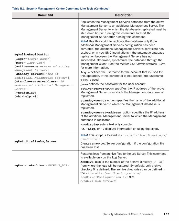
sgOnlineReplication
[login=<login name>][pass=<password>][active-server=<name of active Management Server>][standby-server=<name of additional Management Server>][standby-server-address=<IP address of additional Management Server>][-nodisplay][-h|-help|-?]
Replicates the Management Server’s database from the active Management Server to an additional Management Server. The Management Server to which the database is replicated must be shut down before running this command. Restart the Management Server after running this command.Note! Use this script to replicate the database only if the additional Management Server’s configuration has been corrupted, the additional Management Server’s certificate has expired, or in new SMC installations if the automatic database replication between the Management Servers has not succeeded. Otherwise, synchronize the database through the Management Client. See the McAfee SMC Administrator’s Guide for more information.login defines the username for the account that is used for this operation. If this parameter is not defined, the username root is used.pass defines the password for the user account.active-server option specifies the IP address of the active Management Server from which the Management database is replicated. standby-server option specifies the name of the additional Management Server to which the Management database is replicated.standby-server-address option specifies the IP address of the additional Management Server to which the Management database is replicated.-nodisplay sets a text only console.-h, -help, or -? displays information on using the script.
sgReinitializeLogServer
Note! This script is located in <installation directory>/bin/install.Creates a new Log Server configuration if the configuration file has been lost.
sgRestoreArchive <ARCHIVE_DIR>
Restores logs from archive files to the Log Server. This command is available only on the Log Server. ARCHIVE_DIR is the number of the archive directory (0 – 31) from where the logs will be restored. By default, only archive directory 0 is defined. The archive directories can be defined in the <installation directory>/data/LogServerConfiguration.txt file: ARCHIVE_DIR_xx=PATH.
Table B.1 Security Management Center Command Line Tools (Continued)
Command Description
135Security Management Center Commands

sgRestoreAuthBackup
[-pwd=<password>][-backup=<backup file name>][-nodiskcheck][-h|-help]
Restores the Authentication Server user information from a backup file in the <installation directory>/backups/ directory.Apply the Authentication Server’s configuration after this command.-pwd defines a password for encrypted backup.-backup defines a name for the backup file.-nodiskcheck ignores free disk check before backup restoration.-h or -help displays information on using the script.
sgRestoreLogBackup
[-pwd=<password>][-backup=<backup file name>][-nodiskcheck][-overwrite-syslog-template][-h|-help]
Restores the Log Server (logs and/or configuration files) from a backup file in the <installation directory>/backups/ directory.Apply the Authentication Server’s configuration after this command.-pwd defines a password for encrypted backup.-backup defines a name for the backup file.-nodiskcheck ignores free disk check before backup restoration.-overwrite-syslog-template overwrites a syslog template file if found in the backup.-h or -help displays information on using the script.
sgRestoreMgtBackup
[-pwd=<password>][-backup=<backup file name>][-nodiskcheck][-h|-help]
Restores the Management Server (database and/or configuration files) from a backup file in the <installation directory>/backups/ directory.-pwd defines a password for encrypted backup.-backup defines a name for the backup file.-nodiskcheck ignores free disk check before backup restoration.-h or -help displays information on using the script.
sgRevert
Note! This script is located in <installation directory>/bin/uninstall.Reverts to the previous installation saved during the upgrade process. The previous installation can be restored at any time, even after a successful upgrade.
sgShowFingerPrintDisplays the CA certificate’s fingerprint on the Management Server.
sgStartAuthSrv Starts the Authentication Server.
sgStartLogSrv Starts the Log Server and its database.
sgStartMgtDatabaseStarts the Management Server’s database. There is usually no need to use this script.
Table B.1 Security Management Center Command Line Tools (Continued)
Command Description
136 Appendix B Command Line Tools

sgStartMgtSrv Starts the Management Server and its database.
sgStartWebPortalSrv Starts the Web Portal Server.
sgStopLogSrv Stops the Log Server.
sgStopMgtSrv Stops the Management Server and its database.
sgStopMgtDatabaseStops the Management Server’s database. There is usually no need to use this script.
sgStopWebPortalSrv Stops the Web Portal Server.
sgStopRemoteMgtSrv
[host=<Management Server Host Name>] [login=<login name>][pass=<password>][-h|-help|-?]
Stops the Management Server service when run without arguments. To stop a remote Management Server service, provide the arguments to connect to the Management Server.host is the Management Server’s host name if not localhost.login is an SMC administrator account for the login.pass is the password for the administrator account.-h, -help, or -? displays information on using the script.
Table B.1 Security Management Center Command Line Tools (Continued)
Command Description
137Security Management Center Commands
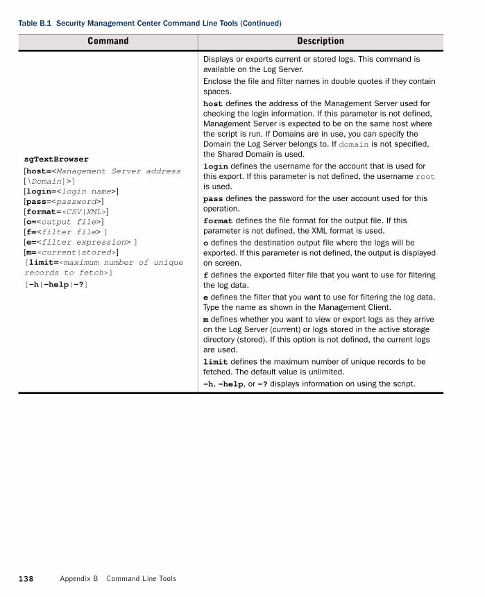
sgTextBrowser
[host=<Management Server address[\Domain]>][login=<login name>][pass=<password>][format=<CSV|XML>][o=<output file>][f=<filter file> ][e=<filter expression> ] [m=<current|stored>][limit=<maximum number of unique records to fetch>]
[-h|-help|-?]
Displays or exports current or stored logs. This command is available on the Log Server.Enclose the file and filter names in double quotes if they contain spaces.host defines the address of the Management Server used for checking the login information. If this parameter is not defined, Management Server is expected to be on the same host where the script is run. If Domains are in use, you can specify the Domain the Log Server belongs to. If domain is not specified, the Shared Domain is used.login defines the username for the account that is used for this export. If this parameter is not defined, the username root is used.pass defines the password for the user account used for this operation.format defines the file format for the output file. If this parameter is not defined, the XML format is used.o defines the destination output file where the logs will be exported. If this parameter is not defined, the output is displayed on screen.f defines the exported filter file that you want to use for filtering the log data.e defines the filter that you want to use for filtering the log data. Type the name as shown in the Management Client. m defines whether you want to view or export logs as they arrive on the Log Server (current) or logs stored in the active storage directory (stored). If this option is not defined, the current logs are used.limit defines the maximum number of unique records to be fetched. The default value is unlimited.-h, -help, or -? displays information on using the script.
Table B.1 Security Management Center Command Line Tools (Continued)
Command Description
138 Appendix B Command Line Tools

NGFW Engine Commands
The commands in the following two tables can be run on the command line on Firewall, Layer 2 Firewall, IPS engines and/or Master Engines.
Note – All command line tools that are available for single Security Engines are also available for Virtual Security Engines that have the same role. However, there is no direct access to the command line of Virtual Security Engines. Commands to Virtual Security Engines must be sent from the command line of the Master Engine using the se-virtual-engine command.
Table B.2 NGFW Engine Command Line Tools
Command Engine Role Description
avdbfetch
[--dbzip=<path to zip file>][--proxy=<proxy address>][--proxy-pass=<proxy password>][--proxy-user=<proxy user>][--url=<url path>]
Firewall
If the separately-licensed anti-virus feature is enabled on a Firewall, use this command to manually update the anti-virus database.--dbzip defines the location of the locally-stored database zip file. This option can be used when there is not an internet connection and you have manually copied the database to a folder on the engine. This parameter does not need to be defined if the zip file is stored in /var/tmp.--proxy defines the address of an HTTP proxy if one is required to connect to the database mirror.--proxy-pass defines the password (if required) for the HTTP proxy.--proxy-user defines the username (if required) for the HTTP proxy.--url defines the address of the database mirror. If not specified, the default address is http://update.nai.com/Products/CommonUpdater.
139NGFW Engine Commands

sg-blacklist show [-v] [-f FILENAME] |add [
[-i FILENAME] | [src IP_ADDRESS/MASK] [src6 IPv6_ADDRESS/PREFIX][dst IP_ADDRESS/MASK][dst6 IPv6_ADDRESS/PREFIX][proto {tcp|udp|icmp|NUM}] [srcport PORT{-PORT}][dstport PORT{-PORT}][duration NUM]] |del [
[-i FILENAME] | [src IP_ADDRESS/MASK] [src6 IPv6_ADDRESS/PREFIX][dst IP_ADDRESS/MASK][dst6 IPv6_ADDRESS/PREFIX][proto {tcp|udp|icmp|NUM}] [srcport PORT{-PORT}][dstport PORT{-PORT}][duration NUM]] |iddel NODE_ID ID |flush
Firewall, Layer 2 Firewall, IPS
Used to view, add, or delete active blacklist entries. The blacklist is applied as defined in Access Rules.Commands:show displays the current active blacklist entries in format: engine node ID | blacklist entry ID | (internal) | entry creation time | (internal) | address and port match | originally set duration | (internal) | (internal). Use the -f option to specify a storage file to view (/data/blacklist/db_<number>). The -v option adds operation’s details to the output.add creates a new blacklist entry. Enter the parameters (see below) or use the -i option to import parameters from a file.del deletes the first matching blacklist entry. Enter the parameters (see below) or use the -i option to import parameters from a file.iddel NODE_ID ID removes one specific blacklist entry on one specific engine. NODE_ID is the engine’s ID, ID is the blacklist entry’s ID (as shown by the show command).flush deletes all blacklist entries.
Table B.2 NGFW Engine Command Line Tools (Continued)
Command Engine Role Description
140 Appendix B Command Line Tools

sg-blacklist (continued)
Firewall, Layer 2 Firewall, IPS
Add/Del Parameters:Enter at least one parameter. The default value is used for the parameters that you omit. You can also save parameters in a text file; each line in the file is read as one blacklist entry.src IP_ADDRESS/MASK defines the source IP address and netmask to match. Matches any IP address by default.src6 IPv6_ADDRESS/PREFIX defines the source IPv6 and prefix length to match. Matches any IPv6 address by default.dst IP_ADDRESS/MASK defines the destination IP address and netmask to match. Matches any IP address by default.dst6 IPv6_ADDRESS/PREFIX defines the destination IPv6 address and prefix length to match. Matches any IPv6 address by default.proto {tcp|udp|icmp|NUM} defines the protocol to match by name or protocol number. Matches all IP traffic by default.srcport PORT[-PORT] defines the TCP/UDP source port or range to match. Matches any port by default.dstport PORT[-PORT] defines the TCP/UDP destination port or range to match. Matches any port by default.duration NUM defines in seconds how long the entry is kept. Default is 0, which cuts current connections, but is not kept.Examples:sg-blacklist add src 192.168.0.2/32 proto tcp dstport 80 duration 60 sg-blacklist add -i myblacklist.txt sg-blacklist del dst 192.168.1.0/24 proto 47
sg-bootconfig
[--primary-console=tty0|ttyS PORT,SPEED][--secondary-console= [tty0|ttyS PORT,SPEED]][--flavor=up|smp][--initrd=yes|no][--crashdump=yes|no|Y@X][--append=kernel options][--help]apply
Firewall, Layer 2 Firewall, IPS
Used to edit boot command parameters for future bootups.--primary-console=tty0|ttyS PORT,SPEED parameter defines the terminal settings for the primary console.--secondary-console= [tty0|ttyS PORT,SPEED] parameter defines the terminal settings for the secondary console.--flavor=up|smp [-kdb] parameter defines whether the kernel is uniprocessor or multiprocessor.--initrd=yes|no parameter defines whether Ramdisk is enabled or disabled.--crashdump=yes|no|Y@X parameter defines whether kernel crashdump is enabled or disabled, and how much memory is allocated to the crash dump kernel (Y). The default is 24M. X must always be 16M.--append=kernel options parameter defines any other boot options to add to the configuration.--help parameter displays usage information.apply command applies the specified configuration options.
Table B.2 NGFW Engine Command Line Tools (Continued)
Command Engine Role Description
141NGFW Engine Commands

sg-clear-all
Firewall, Layer 2 Firewall, IPS
Note! Use this only if you want to clear all configuration information from the engine.This command resets all configuration information from the engine. It does not remove the engine software. After using this command, you must reconfigure the engine using the sg-reconfigure command.
sg-cluster
[-v <virtual engine ID>]
[status [-c SECONDS]]
[versions]
[online]
[lock-online]
[offline]
[lock-offline]
[standby]
[safe-offline]
[force-offline]
Firewall, Layer 2 Firewall, IPS
Used to display or change the status of the node.-v <virtual engine ID> (Master Engine only) option specifies the ID of the Virtual Security Engine on which to execute the command.status [-c SECONDS] command displays cluster status. When -c SECONDS is used, status is shown continuously with the specified number of seconds between updates.version command displays the engine software versions of the nodes in the cluster.online command sends the node online.lock-online command sends the node online and keeps it online even if another process tries to change its state.offline command sends the node offline.lock-offline command sends the node offline and keeps it offline even if another process tries to change its state.standby command sets an active node to standby.safe-offline command sets the node to offline only if there is another online node.force-offline command sets the node online regardless of state or any limitations. Also sets all other nodes offline.
sg-contact-mgmt
Firewall, Layer 2 Firewall, IPS
Used for establishing a trust relationship with the Management Server as part of engine installation or reconfiguration (see sg-reconfigure below). The engine contacts the Management Server using the one-time password created when the engine’s initial configuration is saved.
Table B.2 NGFW Engine Command Line Tools (Continued)
Command Engine Role Description
142 Appendix B Command Line Tools

sg-dynamic-routing [start][stop][restart][force-reload][backup <file>][restore <file>][sample-config][route-table][info]
Firewall
start starts the Quagga routing suite.stop stops the Quagga routing suite and flushes all routes made by zebra.restart restarts the Quagga routing suite.force-reload forces reload of the saved configuration.backup <file> backs up the current configuration to a compressed file.restore <file> restores the configuration from the specified file.sample-config creates a basic configuration for Quagga.route-table prints the current routing table.info displays the help information for the sg-dynamic-routing command, and detailed information about Quagga suite configuration with vtysh.
sg-ipsec -d
[-u <username[@domain]> |-si <session id> |-ck <ike cookie> |-tri <transform id>-ri <remote ip> |-ci <connection id>]
Firewall
Deletes VPN-related information (use vpninfo command to view the information). Option -d (for delete) is mandatory.-u deletes the VPN session of the named VPN client user. You can enter the user account in the form <username@domain> if there are several user storage locations (LDAP domains).-si deletes the VPN session of a VPN client user based on session identifier.-ck deletes the IKE SA (Phase one security association) based on IKE cookie.-tri deletes the IPSEC SAs (Phase two security associations) for both communication directions based on transform identifier.-ri deletes all SAs related to a remote IP address in gateway-to-gateway VPNs.-ci deletes all SAs related to a connection identifier in gateway-to-gateway VPNs.
sg-logger
-f FACILITY_NUMBER -t TYPE_NUMBER
[-e EVENT_NUMBER] [-i "INFO_STRING"][-s] [-h]
Firewall, Layer 2 Firewall, IPS
Used in scripts to create log messages with the specified properties.-f FACILITY_NUMBER parameter defines the facility for the log message.-t TYPE_NUMBER parameter defines the type for the log message.-e EVENT_NUMBER parameter defines the log event for the log message. The default is 0 (H2A_LOG_EVENT_UNDEFINED).-i "INFO_STRING" parameter defines the information string for the log message.-s parameter dumps information on option numbers to stdout-h parameter displays usage information.
Table B.2 NGFW Engine Command Line Tools (Continued)
Command Engine Role Description
143NGFW Engine Commands

sg-raid
[-status] [-add] [-re-add] [-force] [-help]
Firewall, Layer 2 Firewall, IPS
Configures a new hard drive. This command is only for McAfee NGFW appliances that support RAID (Redundant Array of Independent Disks) and have two hard drives.-status option displays the status of the hard drive.-add options adds a new empty hard drive. Use -add -force if you want to add a hard drive that already contains data and you want to overwrite it.-re-add adds a hard drive that is already partitioned. This command prompts for the drive and partition for each degraded array. Use -re-add -force if you want to check all the arrays.-help option option displays usage information.
sg-reconfigure
[--boot][--maybe-contact][--no-shutdown]
Firewall, Layer 2 Firewall, IPS
Used for reconfiguring the node manually.--boot option applies bootup behavior. Do not use this option unless you have a specific need to do so.--maybe-contact option contacts the Management Server if requested. This option is only available on firewall engines.--no-shutdown option allows you to make limited configuration changes on the node without shutting it down. Some changes may not be applied until the node is rebooted.
sg-selftest [-d] [-h] FirewallRuns cryptography tests on the engine.-d option runs the tests in debug mode.-h option displays usage information.
sg-status [-l] [-h]
Firewall, Layer 2 Firewall, IPS
Displays information on the engine’s status.-l option displays all available information on engine status.-h option displays usage information.
Table B.2 NGFW Engine Command Line Tools (Continued)
Command Engine Role Description
144 Appendix B Command Line Tools

sg-toggle-activeSHA1 SIZE |--force [--debug]
Firewall, Layer 2 Firewall, IPS
Switches the engine between the active and the inactive partition. This change takes effect when you reboot the engine.You can use this command, for example, if you have upgraded an engine and want to switch back to the earlier engine version. When you upgrade the engine, the active partition is switched. The earlier configuration remains on the inactive partition. To see the currently active (and inactive) partition, see the directory listing of /var/run/stonegate (ls -l /var/run/stonegate).The SHA1 SIZE option is used to verify the signature of the inactive partition before changing it to active. If you downgrade the engine, check the checksum and the size of the earlier upgrade package by extracting the signature and size files from the sg_engine_[version.build]_i386.zip file.--debug option reboots the engine with the debug kernel.--force option switches the active configuration without first verifying the signature of the inactive partition.
sg-upgrade FirewallUpgrades the node by rebooting from the installation DVD. Alternatively, the node can be upgraded remotely using the Management Client.
sg-version
Firewall, Layer 2 Firewall, IPS
Displays the software version and build number for the node.
se-virtual-engine
-l | --list
-v <virtual engine ID>
-e | --enter
-E “<command [options]>”
-h | --help
Firewall (Master Engine only)
Used to send commands to Virtual Firewalls from the command line of the Master Engine. All commands that can be used for the Firewall role can also be used for Virtual Firewalls.-l or --list list the active Virtual Security Engines.- v <virtual engine ID> specifies the ID of the Virtual Security Engine on which to execute the command.-e or --enter enters the command shell for the Virtual Security Engine specified with the -v option. To exit the command shell, type exit.-E “<command [options]>” executes the specified command on the Virtual Security Engine specified with the -v option.-h or --help shows the help message for the se-virtual-engine command.
Table B.2 NGFW Engine Command Line Tools (Continued)
Command Engine Role Description
145NGFW Engine Commands

The table below lists some general Linux operating system commands that may be useful in running your engines. Some commands can be stopped by pressing Ctrl+c.
sginfo
[-f] [-d] [-s] [-p] [--] [--help]
Firewall, Layer 2 Firewall, IPS
Gathers system information you can send to McAfee support if you are having problems. Use this command only when instructed to do so by McAfee support.-f option forces sgInfo even if the configuration is encrypted.-d option includes core dumps in the sgInfo file.-s option includes slapcat output in the sgInfo file.-p option includes passwords in the sgInfo file (by default passwords are erased from the output).-- option creates the sgInfo file without displaying the progress--help option displays usage information.
Table B.2 NGFW Engine Command Line Tools (Continued)
Command Engine Role Description
Table B.3 General Command Line Tools on Engines
Command Description
dmesg Shows system logs and other information. Use the -h option to see usage.
halt Shuts down the system.
ipDisplays IP address information. Type the command without options to see usage. Example: type ip addr for basic information on all interfaces.
ping Tests connectivity with ICMP echo requests. Type the command without options to see usage.
ps Reports the status of running processes.
reboot Reboots the system.
scp Secure copy. Type the command without options to see usage.
sftp Secure FTP. Type the command without options to see usage.
sshSSH client (for opening a terminal connection to other hosts). Type the command without options to see usage.
tcpdumpGives information on network traffic. Use the -h option to see usage. You can also analyze network traffic by creating tcpdump files from the Management Client with the Traffic Capture feature. See the McAfee SMC Administrator’s Guide for more information.
top Displays the top CPU processes taking most processor time. Use the -h option to see usage.
tracerouteTraces the route packets take to the specified destination. Type the command without options to see usage.
vpninfoDisplays VPN information and allows you to issue some basic commands. Type the command without options to see usage.
146 Appendix B Command Line Tools

Server Pool Monitoring Agent Commands
You can test and monitor the Server Pool Monitoring Agents on the command line with the commands described in the table below.
Table B.4 Server Pool Monitoring Agent Commands
Command Description
agent[-v level]
[-c path]
[test [files]][syntax [files]]
(Windows only) Allows you to test different configurations before activating them.-v level Set the verbosity level. The default level is 5. Levels 6-8 are for debugging where available.-c path Use the specified path as the first search directory for the configuration.test [files]Run in the test mode - status queries do not receive a response. If you specify the files, they are used for reading the configuration instead of the default files. The output is directed to syslog or eventlog instead of the console where the command was run unless you use the -d option.syntax [files]
Check the syntax in the configuration file. If no files are specified, the default configuration files are checked.
sgagentd [-d] [-v level]
[-c path]
[test [files]][syntax [files]]
(Linux only) Allows you to test different configurations before activating them.-d Don’t Fork as a daemon. All log messages are printed to stdout or stderr only.-v level Set the verbosity level. The default level is 5. Levels 6-8 are for debugging where available.-c path Use the specified path as the first search directory for the configuration.test [files]Run in the test mode - status queries do not receive a response. If you specify the files, they are used for reading the configuration instead of the default files. The output is directed to syslog or eventlog instead of the console where the command was run unless you use the -d option.syntax [files]
Check the syntax in the configuration file. If no files are specified, the default configuration files are checked. The output is directed to syslog or eventlog instead of the console where the command was run unless you use the -d option.
147Server Pool Monitoring Agent Commands

sgmon [status|info|proto][-p port] [-t timeout]
[-a id]host
Sends a UDP query to the specified host and waits for a response until received, or until the timeout limit is reached.The request type can be defined as a parameter. If no parameter is given, status is requested. The commands are:status - query the status.info - query the agent version.proto - query the highest supported protocol version.-p port Connect to the specified port instead of the default port.-t timeout Set the timeout (in seconds) to wait for a response.-a id Acknowledge the received log messages up to the specified id. Each response message has an id, and you may acknowledge more than one message at a given time by using the id parameter. Note that messages acknowledged by sgmon will no longer appear in the firewall logs.host The IP address of the host to connect to. To get the status locally, you may give localhost as the host argument. This parameter is mandatory.
Table B.4 Server Pool Monitoring Agent Commands (Continued)
Command Description
148 Appendix B Command Line Tools

APPENDIX C
PREDEFINED ALIASES
This appendix lists the predefined Aliases in the SMC. The predefined Aliases are used in the default policies. Some of them may be useful when you create your own rules.
The following sections are included:
Predefined User Aliases (page 150)System Aliases (page 150)
149

Predefined User Aliases
User Aliases are usually created by administrators, but there are also some predefined user aliases in the SMC. User Aliases are preceded with one $ character. The table below lists all the editable automatically created user Aliases. These Aliases are used in the firewalls’ default DHCP Relay Sub-Policy.
System Aliases
System Aliases are automatically created non-editable Aliases. The System Aliases are preceded with two $$ characters. The table below lists the definitions of all the System Aliases. These Aliases are used in the Firewall’s default policies.
Table C.1 System-defined User Aliases
Predefined User Alias Description
$ DHCP address pools Addresses that can be allocated by DHCP server(s).
$ DHCP address pools for IPsec VPN Clients
Address pools for assigning virtual IP addresses to VPN clients.
$ DHCP servers All DHCP servers defined for the Firewall.
$ DHCP servers for IPsec VPN Clients
The DHCP servers defined for assigning virtual IP addresses to VPN clients.
Table C.2 System Aliases
System Alias Description
$$ DHCP Enabled Interface AddressesIP addresses (of CVIs on clusters) which have DHCP relay enabled.
$$ DHCP Enabled interface addresses for IPsec VPN clients
IP addresses (of NDIs on clusters) which have DHCP relay enabled for VPN Clients.
$$ DHCP Interface X.dnsIP address of the DHCP-assigned DNS server for interface number X.
$$ DHCP Interface X.gatewaysIP address of the DHCP-assigned default router for interface number X.
$$ DHCP Interface X.ip DHCP-assigned IP address for interface number X.
$$ DHCP Interface X.net Network behind the dynamic IP interface number X.
$$ Interface ID X.ip First IP address (CVI) of Physical Interface ID X.
$$ Interface ID X.netDirectly connected networks behind Physical Interface ID X.
$$ Local Cluster All addresses of the cluster.
$$ Local Cluster (CVI addresses only) All CVI addresses of the cluster.
150 Appendix C Predefined Aliases

$$ Local Cluster (DHCP Interface Addresses) All DHCP-assigned IP addresses of the engine.
$$ Local Cluster (NDI addresses only) All NDI addresses of all nodes in the cluster.
$$ Local Cluster (NDI for heartbeat addresses only)
Heartbeat NDI addresses of all nodes in the cluster.
$$ Local Cluster (NDI for management addresses only)
Management NDI address(es) of all nodes in the cluster.
$$ Log Servers IP addresses of all Log Servers.
$$ Management Servers IP addresses of all Management Server.
$$ Valid DHCP Address Pools for IPsec VPN clients
Address pools defined for assigning virtual IP addresses to VPN clients.
$$ Valid DHCP Servers All DHCP servers defined for the Firewall.
$$ Valid DHCP Servers for IPsec VPN clientsThe DHCP servers defined for assigning virtual IP addresses to VPN clients.
Table C.2 System Aliases (Continued)
System Alias Description
151System Aliases

152 Appendix C Predefined Aliases

APPENDIX D
LOG FIELDS
The following sections are included:
Log Entry Fields (page 154)Facility Field Values (page 176)Type Field Values (page 177)Action Field Values (page 178)Event Field Values (page 179)IPsec VPN Log Messages (page 184)Audit Entry Types (page 190)Syslog Entries (page 196)Log Fields Controlled by the Additional Payload Option (page 197)Connection States (page 198)
153

Log Entry Fields
The following tables list the fields of the log entry table and the corresponding XML fields exported to syslog for exportable log entry fields. The rights of the administrator who views the logs and the log type(s) that the administrator has selected for viewing determine which fields are displayed.
• Non-exportable Log Entry Fields.• Exportable Alert Log Entry Fields (page 159).• Exportable Alert Trace Log Entry Fields (page 160).• Exportable Audit Log Entry Fields (page 160).• Exportable Firewall and Layer 2 Firewall Log Entry Fields (page 161).• Exportable IPS Log Entry Fields (page 164).• Exportable IPS Recording Log Entry Fields (page 175).• Exportable SSL VPN Log Entry Fields (page 175).
Non-exportable Log Entry FieldsThe following log entry fields can be displayed in the log table, but cannot be exported to syslog.
Table D.1 Non-exportable Log Entry Fields
Field Description
Additional SituationIdentifier of an additional situation that was detected simultaneously with the situation that triggered the log event.
APN The access point name (APN) of the mobile service in GTP traffic.
Blacklist response.Blacklist duration
Duration of blacklisting in seconds.
Blacklist response.Blacklist executor
Firewall or sensor that blacklisted the traffic that triggered the log event.
Blacklist response.Endpoint1 addr
Blacklisted IP addresses for Endpoint1.
Blacklist response.Endpoint1 mask
Netmask for blacklisted Endpoint1 IP address (32 = host address).
Blacklist response.Endpoint1 port
Blacklisted Endpoint1 port (empty = all ports).
Blacklist response.Endpoint1 port range
Blacklisted Endpoint1 port range.
Blacklist response.Endpoint2 addr
Blacklisted IP addresses for Endpoint2.
Blacklist response.Endpoint2 mask
Netmask for blacklisted Endpoint2 IP address (32 = host address).
154 Appendix D Log Fields

Blacklist response.Endpoint2 port
Blacklisted Endpoint2 port (empty = all ports).
Blacklist response.Endpoint2 port range
Blacklisted Endpoint2 port range.
Blacklist response.Firewall IDID number of firewall node for which the blacklist request is assigned (this must match the Firewall ID given to the blacklist Analyzer module).
Blacklist response.IP Protocol IP protocol of the blacklist response.
Blacklist response.Value missing in
Blacklist Response field for which value resolving failed.
Certificate verify error TLS/SSL Certificate verify error code related to this event.
Correlation base component IDThe policy used to decide a response after successful correlation. Usually the value of this field is the same as “Component ID”, and the field is omitted.
Data type Data type of the log.
Element Domain Administrative Domain of the element associated with the event.
EndpointThe VPN Endpoint through which the traffic that triggered the log event was sent or received.
Ethernet main type Ethernet frame main type (Ethernet 2, IPX, LLC, SNAP).
Event type Description of the event triggered the log creation.
GRE protocol Protocol number of the GRE payload packet.
GRE version Version of the GRE header.
HTTP XFF ClientThe originating IP address of the client that connects to the destination server through one or several HTTP proxy servers.
HTTP XFF ProxiesThe IP addresses of the HTTP proxy servers between the originating client IP address and the destination server.
IMSIThe international mobile subscriber identity of mobile subscriber connecting to the network in GTP traffic.
IP frag conflict range.IP frag different bytes
Total number of conflicting bytes.
IP frag conflict range.IP frag different bytes first
First conflicting byte in the IP fragment.
IP frag conflict range.IP frag different bytes last
Last conflicting byte in the IP fragment.
Table D.1 Non-exportable Log Entry Fields (Continued)
Field Description
155Log Entry Fields

IP frag conflict range.IP frag different new first
Value of the first conflicting byte in the latest fragment.
IP frag conflict range.IP frag different new last
Value of the last conflicting byte in the latest fragment.
IP frag conflict range.IP frag different old first
Value of the first conflicting byte in an earlier fragment.
IP frag conflict range.IP frag different old last
Value of the last conflicting byte in an earlier fragment.
IPv6 extension header typeIPv6 extension header type as indicated by the next header value of the preceding header.
IPv6 extension header’s lengthIPv6 extension header length as indicated by the value of the hdr_ext_len field in the extension header.
IPv6 hop limit Hop limit field in the IPv6 header.
IPv6 option data length IPv6 option data length.
IPv6 option offset IPv6 option offset from the beginning of the IPv6 extension header.
IPv6 option type IPv6 option type.
IPv6 routing final destination Final destination address in the IPv6 routing header.
IPv6 routing header type IPv6 routing header type.
IPv6 routing segments left Segments left value in the IPv6 routing header.
LLC DSAP Logical Link Control Destination Service Access Point.
LLC SSAP Logical Link Control Source Service Access Point.
Log Data TagsThe number of different Log Data Tags associated with the log event. You can see a detailed listing of the Log Data Tags in the Fields panel or the Details view.
Login DomainThe administrative Domain in which the action that triggered the log event was taken.
Message ID The Message Type Value of the GTP message.
MSISDNThe mobile subscriber integrated services digital network-number (MSISDN) of the GTP message.
Normalized URI normalization was used to find the match.
Overview Observed overview.
Overview Name Name of the observed overview.
Overview Section Summary of the observed section definition.
Table D.1 Non-exportable Log Entry Fields (Continued)
Field Description
156 Appendix D Log Fields

Peer VPN GatewayThe peer of the VPN Gateway through which the log event was sent or received.
Reference event ID.Ref Comp Id Sender identifier of the referred event.
Reference event ID.Ref Creation Time
Creation time of the referred event.
Reference event ID.Ref Event ID Identifier of the referred event.
Roles Roles of the Administrator who triggered the event.
Sender Domain Administrative Domain from which the log entry was sent.
Sender module version.Sender build
Build number of the engine that generated the event.
Sender module version.Sender module major
Major version of the engine module that generated the event.
Sender module version.Sender module minor
Minor version of the engine module that generated the event.
Sender module version.Sender module pl
Patch version of the engine module that generated the event.
Sequence Number The sequence number of the GTP message.
SNAP Organization Code Subnetwork Access Protocol Organization Code.
SSL/TLS Domain Domain name field in SSL/TLS certificate related to the event.
State Connection state in connection monitoring.
Subexpression Count The number of concurrent independent subexpressions.
TEID The tunnel end-point identifier (TEID) of the GTP message.
TCP urgent pointer Urgent pointer value in the TCP header.
TCP window size TCP receive window size.
TCP window shrinkage The amount by which the TCP window shrunk.
Threshold Check Time Threshold measurement end time.
Threshold Description Description of threshold limitation.
Threshold Measured Value Value exceeding the threshold.
TLS Alert Description TLS/SSL alert message description.
TLS Alert Level TLS/SSL alert message alert level.
TLS cipher suite TLS/SSL cipher suite.
Table D.1 Non-exportable Log Entry Fields (Continued)
Field Description
157Log Entry Fields

TLS compression method TLS/SSL compression method.
TLS Protocol Version TLS/SSL protocol version.
Tunneled destination The destination IP address of tunneled GTP traffic.
Tunneled source The source IP address of tunneled GTP traffic.
Tunneling levelNumber of tunneling protocol layers encapsulating this protocol layer.
User and Group Information User and Group Information related to the event.
Version The GTP version of the GTP message.
Virus Identifier Virus Identifier.
VPNThe VPN through which the traffic that triggered the log event was sent or received.
VPN Gateway The VPN Gateway through which the log event was sent or received.
Table D.1 Non-exportable Log Entry Fields (Continued)
Field Description
158 Appendix D Log Fields

Exportable Alert Log Entry Fields
Table D.2 Alert Log Entry Fields
Field Syslog Export Field Description
Acknowledged ACK Acknowledged alert.
Alert Type ALERT Type of alert.
Component ID COMP_ID The identifier of the creator of the log entry.
Creation Time TIMESTAMP Log entry creation time.
Data Identifier LOG_ID Data Identifier of the log entry.
Dst Addr DST Packet destination IP address.
Event ID EVENT_ID Event identifier, unique within one sender.
Information message
INFO_MSG A description of the log event that further explains the entry.
Protocol PROTOCOL Connection IP protocol.
Reception time RECEPTION_TIME Time when the entry was received by the Log Server.
Reference event ID
REF_EVENT Reference to a related event.
Rule Tag RULE_ID Rule tag of the rule that triggered the log event.
Sender NODE_ID IP address of the engine or server that sent the log entry.
Sender type SENDER_TYPE The type of engine or server that sent the log entry.
Severity ALERT_SEVERITY Severity of the situation related to the alert event.
Situation SITUATION The identifier of the situation that triggered the log event.
Situation Type SIT_CATEGORY The type of the situation that triggered the log event.
159Log Entry Fields

Exportable Alert Trace Log Entry Fields
Exportable Audit Log Entry Fields
Table D.3 Alert Trace Log Entry Fields
Field Syslog Export Field Description
Address EVENT_ADDRESS Destination for the alert notification.
Alert Event EVENT_TYPE Type of alert event.
Alert Identifier EVENT_LOG_ID Data Identifier of the alert.
Alert Time EVENT_TIME Timestamp of the alert.
Component ID COMP_ID The identifier of the creator of the log entry.
Creation Time TIMESTAMP Log entry creation time.
Data Identifier LOG_ID Data Identifier of the log entry.
Event description EVENT_INFO Description of the alert event.
Storage Server STORAGE_SERVER_ID Server where the alert is stored.
User EVENT_USER User who executed the action that produced the alert.
Table D.4 Audit Log Entry Fields
Field Syslog Export Field Description
Administrator USER_ORIGINATOR Administrator who triggered the audit event.
Client IP address CLIENT_IP_ADDRESS Address of the client that triggered the audit event.
Component ID COMP_ID The identifier of the creator of the log entry.
Creation Time TIMESTAMP Log entry creation time.
Elements OBJECT_NAME Elements being manipulated in the audit event.
Event ID EVENT_ID Event identifier, unique within one sender.
Incident case INCIDENT_CASEThe Incident case to which the logs and/or audit events are related.
Information message
INFO_MSG A description of the log event that further explains the entry.
Operation type TYPE_DESCRIPTION Type of action that triggered the audit entry.
Origin name ORIGIN_NAME Name of the component that triggered the audit event.
Result RESULT Result state after the audited event.
Sender NODE_ID IP address of the engine or server that sent the log entry.
160 Appendix D Log Fields

Exportable Firewall and Layer 2 Firewall Log Entry Fields
Sender type SENDER_TYPE The type of engine or server that sent the log entry.
Table D.4 Audit Log Entry Fields (Continued)
Field Syslog Export Field Description
Table D.5 Firewall Log Entry Fields
Field Syslog Export Field Description
Acknowledged ACK Acknowledged alert.
Action ACTION
Action of the rule that triggered the log event. The action values are Allow, Discard, Refuse, Terminate, Wait for further actions, and Wait for authentication. For more information on action values, see the table Table D.12.
Alert Type ALERT Type of alert.
Auth. Rule Tag AUTH_RULE_ID Rule number of the rule that triggered the log event.
Auth. User AUTH_NAME Username of the authorized user related to this event.
Bytes Rcvd ACC_RX_BYTES Number of bytes received during the connection.
Bytes Sent ACC_TX_BYTESNumber of bytes sent during the connection. The number of bytes sent is counted when accounting entries are created.
Component ID COMP_ID The identifier of the creator of the log entry.
Creation Time TIMESTAMP Log entry creation time.
Data Identifier LOG_ID Data Identifier of the log entry.
DSCP Mark DSCP_MARKThe DSCP Mark associated with the traffic that triggered the log event.
Dst Addr DST Packet destination IP address.
Dst Port DPORT TCP or UDP destination port in the packet header.
Dst VPN VPN_ID The destination VPN of the connection.
Elapsed Time ACC_ELAPSEDElapsed time of the connection in seconds. The elapsed time is recorded when accounting entries are created at the time of connection closing.
Event EVENTThe event that triggered the log creation, for example, New connection, Connection closed, Connection discarded. For more information on event values, see the table Table D.12.
Event ID EVENT_ID Event identifier, unique within one sender.
Facility FACILITYFirewall subsystem that generated the log event. For more information on facility values, see the table Table D.9.
161Log Entry Fields

FP situation FP_SITUATION Situation identifier of a matching fingerprint.
ICMP code ICMP_CODEICMP code field. ICMP code provides further information about message type (for example, network unreachable). For more information, refer to RFC 792 and RFC 950.
ICMP ID ICMP_ID
The ICMP identifier recorded by the engine when ICMP packets pass through the firewall. The ICMP identifier may be used by the echo sender to aid in matching the replies with the echo requests. For example, the identifier might be used like a port in TCP or UDP to identify a session. For more information on ICMP ID and the ICMP protocol, refer to RFC 792 and RFC 950.
IKE Cookie IKE_COOKIE IKE Cookie used in the VPN negotiation.
Information message
INFO_MSG A description of the log event that further explains the entry.
IPsec SPI IPSEC_SPIThe IPsec Security Parameter Index (SPI) is the connection identifier of the IPsec connection. The IPsec SPI value is displayed as a hexadecimal number.
NAT Dst NAT_DST Translated packet destination IP address.
NAT Dst Port NAT_DPORT Translated packet destination protocol port.
Nat Rule Tag NAT_RULE_ID The rule number of the NAT rule that triggered the log event.
NAT Src NAT_SRC Translated packet source IP address.
NAT Src Port NAT_SPORT Translated packet source protocol port.
Packets Rcvd ACC_RX_PACKETSThe number of packets that are received during the connection.
Packets Sent ACC_TX_PACKETS The number of packets that are sent during the connection.
Priority QOS_PRIORITYThe priority assigned to the traffic according to the QoS policy.
Protocol PROTOCOL Connection IP protocol.
Protocol Agent SRVHELPER_ID Protocol Agent numerical ID code.
QoS Class QOS_CLASSThe Quality of Service class assigned to the traffic according to the QoS policy.
Reception time RECEPTION_TIME Time when the entry was received by the Log Server.
Reference event ID REF_EVENT Reference to a related event.
Round trip RTTRound trip time for outbound Multi-Link link testing. Time indicated is from sending queries to the first reply. The unit is 0.01 seconds.
Table D.5 Firewall Log Entry Fields (Continued)
Field Syslog Export Field Description
162 Appendix D Log Fields

Rule Tag RULE_ID Rule tag of the rule that triggered the log event.
Sender NODE_ID IP address of the engine or server that sent the log entry.
Sender type SENDER_TYPE The type of engine or server that sent the log entry.
Service SERVICESpecial field for filtering logs using the defined services. Does not appear in the log entry table.
Severity ALERT_SEVERITY Severity of the situation related to the log event.
Situation SITUATION The identifier of the situation that triggered the log event.
Situation Type SIT_CATEGORY The type of the situation that triggered the log event.
SNMP Return Src IF SNMP_RET_SRC_IF The SNMP index of the return source interface.
SNMP Src IF SNMP_SRC_IF The SNMP index of the source interface.
Src Addr SRC Packet source IP address.
Src IF Srcif Defined source interface number for the firewall cluster.
Src Port SPORT TCP or UDP source port in the packet header.
Src VLAN SRC_VLAN The source VLAN ID number (up to 4095).
Src VPN VPN_SRC_ID The source VPN of the connection.
Syslog SYSLOG_TYPE
Syslog is a system service used in some operating systems, for example, UNIX- and software packages. For more information on syslog and syslog types, refer to RFC 3164.
Type TYPELog entry severity type. For more information on type values, see the table Table D.10.
Table D.5 Firewall Log Entry Fields (Continued)
Field Syslog Export Field Description
163Log Entry Fields

Exportable IPS Log Entry Fields
Table D.6 IPS Log Entry Fields
Field Syslog Export Field Description
Agent mem usage AGENT_MEMUSAGE Memory usage of each IPS agent.
Alert Type ALERT Type of alert.
Attacker IP IP_ATTACKER IPv4 address of the attacking host.
Blacklist executor FIREWALL_IDFirewall that blacklisted the traffic that triggered the log event.
Blacklist response BLACKLIST_RESPONSE Firewall blacklist response that triggered the log event.
Cluster ID CLUSTER_IDThe identifier of the cluster to which the node that created the log entry belongs.
Component ID COMP_ID The identifier of the creator of the log entry.
Connection analysis end
CONNECTION_ANALYSIS_END The application could not continue analyzing the traffic stream after this event.
Connection dropped DROP_CONNECTIONThe connection was dropped by a Drop Response in the rule.
Content type of message body
SIP_CONTENT_TYPE Content type of the SIP message body.
Correlation base component ID
CORRELATION_COMP_IDThe policy that decides the response after successful correlation.
Correlation begin time
TIME_FRAME_BEGINNTP stamp of the beginning of the time frame for a match to a correlation situation.
Correlation end time
TIME_FRAME_ENDNTP stamp of the end of the time frame for a match to a correlation situation.
Creation Time TIMESTAMP Log entry creation time.
Data Identifier LOG_ID Data Identifier of the log entry.
Datagram dropped DROP_DATAGRAMThe datagram was dropped by a Drop Response in the rule.
Destination port PORT_DESTTCP or UDP destination port in the packet header. Included only for backwards compatibility with legacy IPS engines. For other cases, use Dst Port.
DNS class DNS_CLASS DNS resource record class.
DNS hdr ancount DNS_HDR_ANCOUNT DNS answers count.
DNS hdr arcount DNS_HDR_ARCOUNT DNS additional section count.
DNS hdr flag tc DNS_HDR_FLAG_TC DNS header flag TC.
164 Appendix D Log Fields

DNS hdr id DNS_HDR_ID DNS message ID.
DNS hdr is request DNS_HDR_IS_REQUEST DNS message is a request.
DNS hdr nscount DNS_HDR_NSCOUNT DNS authority section count.
DNS hdr opcode DNS_HDR_OPCODE DNS operation code.
DNS hdr qdcount DNS_HDR_QDCOUNT DNS questions count.
DNS hdr rcode DNS_HDR_RCODE DNS return code.
DNS name length DNS_NAME_LENGTH Length of DNS name in a message.
DNS offset DNS_OFFSET DNS message offset where the situation occurs.
DNS pointer DNS_POINTER Name pointer in a DNS message.
DNS qclass DNS_QCLASS Query resource record class in a DNS message.
DNS qname DNS_QNAME First queried name in a DNS message.
DNS qtype DNS_QTYPE Query type in a DNS message.
DNS section DNS_SECTION Section name in a DNS message.
DNS type DNS_TYPE DNS resource record type.
DNS UDP payload DNS_UDP_PAYLOAD UDP payload size of a DNS message.
DNS UDP payload by opt
DNS_UDP_PAYLOAD_BY_OPT UDP payload advertised in a DNS OPT record.
Dst Addr DST Packet destination IP address.
Dst Port DPORT TCP or UDP destination port in the packet header.
Elapsed Time ACC_ELAPSEDElapsed time of the connection in seconds. The elapsed time is recorded when accounting entries are created at the time of connection closing.
Error id ERROR_ID Identifier of the error that triggered the log event.
Eth frame length ETH_FRAME_LENGTH Length of the Ethernet frame.
Eth min frame length
ETH_MIN_FRAME_LENGTH Minimum length for Ethernet frame.
Ethernet type ETH_TYPE Type field in Ethernet frame.
Event count EVENT_COUNT Event count in the defined time frame.
Event ID EVENT_ID Event identifier, unique within one sender.
Event update EVENT_UPDATE Event ID for which this event is an update.
Table D.6 IPS Log Entry Fields (Continued)
Field Syslog Export Field Description
165Log Entry Fields

Excerpt data EXCERPTShort recording of the application level data stream of the attack.
Excerpt position EXCERPT_POS Position in the attached short recording.
Failed response cnt FAILED_RESP_CNT Number of failed response attempts.
Fields updatable FIELDS_UPDATABLE Map of updatable log fields.
FP situation FP_SITUATION Situation identifier of a matching fingerprint.
Frame dropped DROP_FRAME The frame was dropped by a Drop Response in the rule.
From address SIP_FROM SIP From address.
FTP account len FTP_ACCOUNT_LEN Length of the FTP account string.
FTP adat argument len
FTP_ADAT_ARG_LEN Length of ADAT command argument.
FTP allocate size FTP_ALLOCATE_SIZE Size of FTP allocate.
FTP arg len FTP_ARG_LEN Length of the FTP command argument.
FTP auth arg len FTP_AUTH_ARG_LEN Length of the AUTH argument.
FTP client state name
FTP_CLIENT_STATE_NAME The detected FTP client state.
FTP clnt arg len FTP_CLNT_ARG_LEN Length of the FTP CLNT argument.
FTP command FTP_COMMAND Name of the FTP command.
FTP conf arg len FTP_CONF_ARG_LEN Length of the CONF command argument.
FTP enc arg len FTP_ENC_ARG_LEN Length of the ENC command argument.
FTP eprt arg len FTP_EPRT_ARG_LEN Length of the EPRT command argument.
FTP estp arg len FTP_ESTP_ARG_LEN Length of the ESTP command argument.
FTP help arg len FTP_HELP_ARG_LEN Length of the HELP command argument.
FTP lang arg len FTP_LANG_ARG_LEN Length of the LANG command argument.
FTP lprt arg len FTP_LPRT_ARG_LEN Length of the LPRT command argument.
FTP marker len FTP_MARKER_LEN Length of the REST command argument.
FTP mic arg len FTP_MIC_ARG_LEN Length of the MIC command argument.
FTP opts arg len FTP_OPTS_ARG_LEN Length of the OPTS command argument.
FTP password len FTP_PASSWORD_LEN Length of the detected FTP password.
FTP pathname len FTP_PATHNAME_LEN Length of the detected FTP pathname.
Table D.6 IPS Log Entry Fields (Continued)
Field Syslog Export Field Description
166 Appendix D Log Fields

FTP protection buffer size
FTP_PROTECTION_BUFFER_ SIZE
Size of the detected PBSZ protection buffer.
FTP reply FTP_REPLY The detected FTP server reply.
FTP reply code FTP_REPLY_CODE The detected FTP server reply code.
FTP reply len FTP_REPLY_LEN Length of an FTP server reply that is too long.
FTP reply line len FTP_REPLY_LINE_LEN Length of an FTP server reply line that is too long.
FTP server action FTP_SERVER_ACTION FTP server action after a suspicious client command.
FTP server banner FTP_SERVER_BANNER The detected FTP server banner.
FTP server state name
FTP_SERVER_STATE_NAME The detected FTP server state.
FTP site arg len FTP_SITE_ARG_LEN Length of the SITE command argument.
FTP state name FTP_STATE_NAME The detected FTP session state.
FTP username len FTP_USERNAME_LEN Length of the detected FTP username.
HTTP content length HTTP_CONTENT_LENGTH HTTP content length.
HTTP content type HTTP_CONTENT_TYPE HTTP content type.
HTTP header HTTP_HEADER The detected HTTP header field.
HTTP header name HTTP_HEADER_NAME The detected HTTP header field name.
HTTP no request HTTP_NO_REQUESTThe detected HTTP response could not be associated to any request.
HTTP request host HTTP_REQUEST_HOST HTTP request host.
HTTP request line HTTP_REQUEST_LINE The detected HTTP request line.
HTTP request message field name length
HTTP_REQUEST_MESSAGE_ FIELD_NAME_LENGTH
Length of the HTTP request header field name.
HTTP request message field value length
HTTP_REQUEST_MESSAGE_ FIELD_VALUE_LENGTH
Length of the HTTP request header field value.
HTTP request method
HTTP_REQUEST_METHOD The detected HTTP request method.
HTTP request URI HTTP_REQUEST_URI The detected HTTP request URI.
HTTP request version
HTTP_REQUEST_VERSION The detected HTTP request version.
Table D.6 IPS Log Entry Fields (Continued)
Field Syslog Export Field Description
167Log Entry Fields

HTTP requests not stored
HTTP_REQUESTS_NOT_ STORED
Number of requests not stored due to HTTP pipeline overflow.
HTTP response code
HTTP_RESPONSE_CODE The detected HTTP response code.
HTTP response message field name length
HTTP_RESPONSE_MESSAGE_FIELD_NAME_LENGTH
Length of the HTTP response header field name.
HTTP response message field value length
HTTP_RESPONSE_MESSAGE_FIELD_VALUE_LENGTH
Length of the HTTP response header field value.
HTTP URI length HTTP_URI_LENGTH Length of HTTP request URI
ICMP code ICMP_CODEICMP code field. ICMP code provides further information about message type (for example, network unreachable). For more information, refer to RFC 792 and RFC 950.
ICMP expected message length
ICMP_EXPECTED_MESSAGE_LENGTH
Expected length of the ICMP message.
ICMP field addr entry size
ICMP_FIELD_ADDR_ENTRY_SIZE
Value of the detected ICMP address entry size field.
ICMP field address mask
ICMP_FIELD_ADDRESS_ MASK
Value of detected ICMP address mask field.
ICMP field domain name
ICMP_FIELD_DOMAIN_NAME Value of the detected ICMP domain name field.
ICMP field gateway IP addr
ICMP_FIELD_GATEWAY_IP_ ADDR
Value of the detected ICMP gateway address field.
ICMP field lifetime ICMP_FIELD_LIFETIME Value of the ICMP lifetime field.
ICMP field num addrs
ICMP_FIELD_NUM_ADDRS Value of the ICMP number of addresses field.
ICMP field originate timestamp
ICMP_FIELD_ORIGINATE_ TIMESTAMP
Value of the ICMP originate timestamp field.
ICMP field outbound hop count
ICMP_FIELD_OUTBOUND_ HOP_COUNT
Value of the ICMP outbound hop count field.
ICMP field output link mtu
ICMP_FIELD_OUTPUT_LINK_MTU
Value of the ICMP output link MTU field.
ICMP field output link speed
ICMP_FIELD_OUTPUT_LINK_ SPEED
Value of the ICMP output link speed field.
ICMP field pointer ICMP_FIELD_POINTERThe offset in the related datagram where the situation occurred.
Table D.6 IPS Log Entry Fields (Continued)
Field Syslog Export Field Description
168 Appendix D Log Fields

ICMP field preference level
ICMP_FIELD_PREFERENCE_ LEVEL
Value of the ICMP preference level field.
ICMP field receive timestamp
ICMP_FIELD_RECEIVE_ TIMESTAMP
Value of the ICMP receive timestamp field.
ICMP field return hop count
ICMP_FIELD_RETURN_HOP_ COUNT
Value of the ICMP return hop count field.
ICMP field router addr
ICMP_FIELD_ROUTER_ ADDRESS
Value of the ICMP router address field.
ICMP field sequence num
ICMP_FIELD_SEQUENCE_ NUMBER
Value of the ICMP sequence number field.
ICMP field traceroute id
ICMP_FIELD_TRACEROUTE_ID Value of the ICMP traceroute ID field.
ICMP field transmit timestamp
ICMP_FIELD_TRANSMIT_ TIMESTAMP
Value of the ICMP transmit timestamp field.
ICMP ID ICMP_ID
The ICMP identifier recorded by the engine when ICMP packets pass through the firewall. The ICMP identifier may be used by the echo sender to aid in matching the replies with the echo requests. For example, the identifier might be used like a port in TCP or UDP to identify a session. For more information on ICMP ID and the ICMP protocol, refer to RFC 792 and RFC 950.
ICMP message length
ICMP_MESSAGE_LENGTH Length of the ICMP message.
ICMP referenced destination IP addr
ICMP_REFERENCED_ DESTINATION_IP_ADDR
Destination IP address of the datagram related to the ICMP message.
ICMP referenced destination port
ICMP_REFERENCED_ DESTINATION_PORT
Destination port of the datagram related to the ICMP message.
ICMP referenced IP proto
ICMP_REFERENCED_IP_ PROTO
IP Protocol field of the datagram related to the ICMP message.
ICMP referenced source IP addr
ICMP_REFERENCED_SOURCE_IP_ADDR
Source IP address of the datagram related to the ICMP message.
ICMP referenced source port
ICMP_REFERENCED_SOURCE_PORT
Source port of IP datagram related to the ICMP message.
Table D.6 IPS Log Entry Fields (Continued)
Field Syslog Export Field Description
169Log Entry Fields

ICMP Type ICMP_TYPE
The Internet Control Message Protocol is an extension to the Internet Protocol (IP) that supports packets containing error, control and informational messages. ICMP messages are sent using the basic IP header. The first octet of the data portion of the datagram is an ICMP type field. For more information, refer to RFC 792 and RFC 950.
Imf encoded word IMF_ENCODED_WORD Encoded word token related to this event.
Imf header field IMF_HEADER_FIELDContents (possibly partial) of the mail header field related to this event.
Imf header field name
IMF_HEADER_FIELD_NAME Name of the mail header field related to this event.
Imf header field position
IMF_HEADER_FIELD_ POSITION
Number of characters processed in this header field when this event was generated.
Imf token IMF_TOKEN Syntactical token in the mail body related to this event.
Imf token length IMF_TOKEN_LENGTHLength of the syntactical token in the mail body related to this event.
Information message
INFO_MSGA description of the log event that further explains the entry.
Inspection check parameter
MODPAR_VA List of agent parameters and the defined values.
IP checksum IP_CHECKSUM Value of the IP header checksum.
IP datagram length IP_DATAGRAM_LENGTH Length of the IP datagram.
IP datagram new length
IP_DATAGRAM_NEW_LENGTH The new suggested length for the IP datagram.
IP destination IP_DESTDestination IP address in the packet header. Included only for backwards compatibility for legacy IPS. For other cases, use Dst Addr.
IP frag conflict range
IP_FRAG_CONFLICT_RANGE AGMENT_OFFSET
Conflicting byte range in a fragment.
IP fragment offset IP_FRAGMENT_OFFSET Fragment offset in the IP header.
IP header length IP_HEADER_LENGTH Length of the IP header.
IP identification IP_IDENTIFICATION Identification field in the IP header.
IP offset IP_OFFSET Start IP offset from the beginning of the Ethernet frame.
IP option length IP_OPTION_LENGTH Length of the IP option that triggered the response.
IP option number IP_OPTION_NUMBER IP option number that triggered the response.
Table D.6 IPS Log Entry Fields (Continued)
Field Syslog Export Field Description
170 Appendix D Log Fields
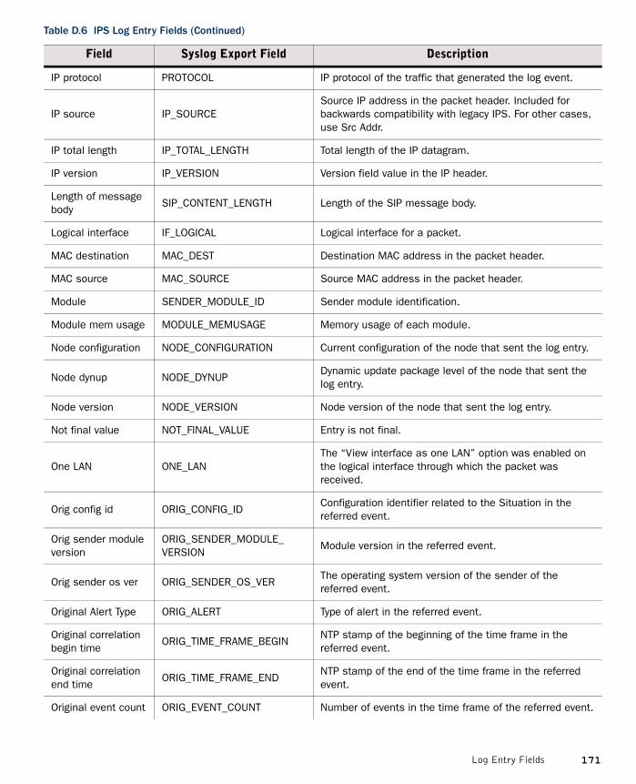
IP protocol PROTOCOL IP protocol of the traffic that generated the log event.
IP source IP_SOURCESource IP address in the packet header. Included for backwards compatibility with legacy IPS. For other cases, use Src Addr.
IP total length IP_TOTAL_LENGTH Total length of the IP datagram.
IP version IP_VERSION Version field value in the IP header.
Length of message body
SIP_CONTENT_LENGTH Length of the SIP message body.
Logical interface IF_LOGICAL Logical interface for a packet.
MAC destination MAC_DEST Destination MAC address in the packet header.
MAC source MAC_SOURCE Source MAC address in the packet header.
Module SENDER_MODULE_ID Sender module identification.
Module mem usage MODULE_MEMUSAGE Memory usage of each module.
Node configuration NODE_CONFIGURATION Current configuration of the node that sent the log entry.
Node dynup NODE_DYNUPDynamic update package level of the node that sent the log entry.
Node version NODE_VERSION Node version of the node that sent the log entry.
Not final value NOT_FINAL_VALUE Entry is not final.
One LAN ONE_LANThe “View interface as one LAN” option was enabled on the logical interface through which the packet was received.
Orig config id ORIG_CONFIG_IDConfiguration identifier related to the Situation in the referred event.
Orig sender module version
ORIG_SENDER_MODULE_ VERSION
Module version in the referred event.
Orig sender os ver ORIG_SENDER_OS_VERThe operating system version of the sender of the referred event.
Original Alert Type ORIG_ALERT Type of alert in the referred event.
Original correlation begin time
ORIG_TIME_FRAME_BEGINNTP stamp of the beginning of the time frame in the referred event.
Original correlation end time
ORIG_TIME_FRAME_ENDNTP stamp of the end of the time frame in the referred event.
Original event count ORIG_EVENT_COUNT Number of events in the time frame of the referred event.
Table D.6 IPS Log Entry Fields (Continued)
Field Syslog Export Field Description
171Log Entry Fields
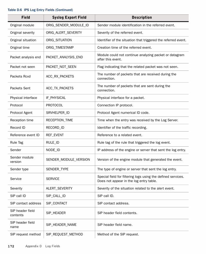
Original module ORIG_SENDER_MODULE_ID Sender module identification in the referred event.
Original severity ORIG_ALERT_SEVERITY Severity of the referred event.
Original situation ORIG_SITUATION Identifier of the situation that triggered the referred event.
Original time ORIG_TIMESTAMP Creation time of the referred event.
Packet analysis end PACKET_ANALYSIS_ENDModule could not continue analyzing packet or datagram after this event.
Packet not seen PACKET_NOT_SEEN Flag indicating that the related packet was not seen.
Packets Rcvd ACC_RX_PACKETSThe number of packets that are received during the connection.
Packets Sent ACC_TX_PACKETSThe number of packets that are sent during the connection.
Physical interface IF_PHYSICAL Physical interface for a packet.
Protocol PROTOCOL Connection IP protocol.
Protocol Agent SRVHELPER_ID Protocol Agent numerical ID code.
Reception time RECEPTION_TIME Time when the entry was received by the Log Server.
Record ID RECORD_ID Identifier of the traffic recording.
Reference event ID REF_EVENT Reference to a related event.
Rule Tag RULE_ID Rule tag of the rule that triggered the log event.
Sender NODE_ID IP address of the engine or server that sent the log entry.
Sender module version
SENDER_MODULE_VERSION Version of the engine module that generated the event.
Sender type SENDER_TYPE The type of engine or server that sent the log entry.
Service SERVICESpecial field for filtering logs using the defined services. Does not appear in the log entry table.
Severity ALERT_SEVERITY Severity of the situation related to the alert event.
SIP call ID SIP_CALL_ID SIP call ID.
SIP contact address SIP_CONTACT SIP contact address.
SIP header field contents
SIP_HEADER SIP header field contents.
SIP header field name
SIP_HEADER_NAME SIP header field name.
SIP request method SIP_REQUEST_METHOD Method of the SIP request.
Table D.6 IPS Log Entry Fields (Continued)
Field Syslog Export Field Description
172 Appendix D Log Fields

SIP request URI SIP_REQUEST_URI URI of the SIP request.
SIP request version SIP_REQUEST_VERSION Version of the SIP request.
SIP response reason-phrase
SIP_RESPONSE_REASON_ PHRASE
SIP response reason-phrase.
SIP response status code
SIP_RESPONSE_STATUS_ CODE
Status code of the SIP response.
SIP VIA address SIP_VIA SIP VIA address.
Situation SITUATION The identifier of the situation that triggered the log event.
Situation Type SIT_CATEGORY The type of the situation that triggered the log event.
SMTP command SMTP_COMMAND Suspicious SMTP command sent by the client.
SMTP mail stats SMTP_MAIL_STATS Statistics on e-mail messages.
SMTP misplaced command
SMTP_MISPLACED_ COMMAND
Command given in the wrong place in the command sequence.
SMTP recipient SMTP_RECIPIENT Recipient forward path in RCPT command parameter.
SMTP reply SMTP_REPLY Suspicious SMTP reply message sent by the server.
SMTP reverse path SMTP_REVERSE_PATH SMTP reverse path in MAIL FROM command parameter.
SMTP server action SMTP_SERVER_ACTIONSuspicious server action after a suspicious client command.
SMTP server banner SMTP_SERVER_BANNERBanner sent by the SMTP server at the beginning of the connection.
SMTP transaction state
SMTP_TRANSACTION_STATE Session state of the SMTP transaction.
SNMP Return Src IF SNMP_RET_SRC_IF The SNMP index of the return source interface.
SNMP Src IF SNMP_SRC_IF The SNMP index of the source interface.
Source file SOURCE_FILE Name of the source file.
Source file line SOURCE_FILE_LINE) Line number in the source file.
Source port PORT_SOURCETCP or UDP source port in the packet header. Included for backwards compatibility with legacy IPS. For other cases, see Src Port.
Src Addr SRC Packet source IP address.
Src Port SPOR TCP or UDP source port in the packet header.
SSH calc client crypto bit ratio
SSH_CALC_CLIENT_CRYPTO_BIT_RATIO
Calculated SSH client crypto bit ratio.
Table D.6 IPS Log Entry Fields (Continued)
Field Syslog Export Field Description
173Log Entry Fields

SSH calc server crypto bit ratio
SSH_CALC_SERVER_CRYPTO_BIT_RATIO
Calculated SSH server crypto bit ratio.
SSH1 host key bits SSH1_HOST_KEY_BITS Bit length of the SSHv1 host key.
SSH1 server key bits
SSH1_SERVER_KEY_BITS Bit length of the SSHv1 server key.
Syslog SYSLOG_TYPE
Syslog is a system service used in some operating systems, for example, UNIX- and software packages. For more information on syslog and syslog types, refer to RFC 3164.
Target IP IP_TARGET IPv4 address of the target host in a detected attack.
TCP connection start time
TCP_CONNECTION_START_ TIME
Start time of the TCP connection.
TCP handshake seen
TCP_HANDSHAKE_SEEN Initial handshake of the TCP connection detected.
TCP option kind TCP_OPTION_KIND Type of the TCP option.
TCP option length TCP_OPTION_LENGTH Length of the TCP option that caused the response.
To address SIP_TO SIP To address.
UDP datagram size UDP_DATAGRAM_SIZE Size of the UDP datagram.
Vulnerability References
VULNERABILITY_ REFERENCES
References to known vulnerabilities in a vulnerability database. Generated from situation and original situation.
Whole session seen WHOLE_SESSION_SEENTrue if no data of this session has been missed up to this point.
Table D.6 IPS Log Entry Fields (Continued)
Field Syslog Export Field Description
174 Appendix D Log Fields

Exportable IPS Recording Log Entry FieldsThe following log entry fields are included in log data when you export IPS traffic recordings.
Exportable SSL VPN Log Entry Fields
Table D.7 IPS Recording Log Entry Fields
Field Syslog Export Field Description
Component ID COMP_ID The identifier of the creator of the log entry.
Creation Time TIMESTAMP Log entry creation time.
Packet data PACKET_DATA Recorded packet data.
Record frame cached
RECORD_FRAME_CACHEDMarker showing that this frame was received before the recording was started. The frame included in the recording was taken from a memory cache.
Record IDRECORD_ID (IPS and IPS recording only)
Identifier of the traffic recording.
Sender NODE_ID IP address of the engine or server that sent the log entry.
Table D.8 SSL VPN Log Entry Fields
Field Syslog Export Field Description
Application APPLICATION The SSL VPN service that generated the log.
Application Detail APPLICATION_DETAILThe type of log sent by the SSL VPN. Possible values: SYSTEM, AUDIT, HTTP, DEBUG, BILLING, RADIUS, EVENT.
Creation Time TIMESTAMP Log entry creation time.
Information message
INFO_MSG A description of the log event that further explains the entry.
Reception time RECEPTION_TIME Time when the entry was received by the Log Server.
Sender NODE_ID IP address of the engine or server that sent the log entry.
Username USERNAME Username of the user to which this log event is related.
Message Id MESSAGE_ID SSL VPN-internal identifier of the log entry.
Session Id SESSION_ID ID of the User Session.
Log Severity LOG_SEVERITYThe severity assigned to the log entry by the SSL VPN-internal logging system. Possible values: Debug, Fatal, Info, Unknown, Warning.
175Log Entry Fields

Facility Field Values
The following table lists the possible values for the Facility field in the log table.
Table D.9 Facility Field Values
Value
Accounting
Authentication
Blacklisting
Cluster Daemon
Cluster Protocol
Connection Tracking
Data Synchronization
DHCP Client
DHCP Relay
Invalid
IPsec
License
Load-Balancing Filter
Log Server
Logging System
Management
Monitoring
NetLink Incoming HA
Network Address Translation
Packet Filter
Protocol Agent
Server Pool
SNMP Monitoring
State Synchronization
Syslog
System
176 Appendix D Log Fields

Type Field Values
The following table lists the possible values for the Type field in the log table.
Tester
Undefined
User Defined
Table D.9 Facility Field Values (Continued)
Value
Table D.10 Type Field Values
Value
Critical Error
Debug high
Debug low
Debug mid
Diagnostic
Emergency - System Unusable
Error
Informational
Internal max
Max
Notification
System Alert
Undefined
Warning
177Type Field Values

Action Field Values
The following table shows the most common log occurrences for the Action field.
Table D.11 Action Field Values
Action Description
Allow
A connection was allowed through the engine. This can be a new connection, a related connection (for example, an FTP data connection), a related packet (for example ICMP error messages related to an earlier TCP connection), or a new connection through an existing VPN tunnel.
Discard A connection or packet was discarded by the engine.
PermitA connection was allowed through according to the Inspection Rules on the engine.
Refuse A connection was refused by the engine.
Terminate A connection was terminated by the engine.
Terminate (failed) An attempt to terminate a connection failed.
Terminate (passive)A connection matched a rule with the passive Terminate action, and a log entry indicating that the connection would have been terminated was produced.
Terminate (reset)A connection was terminated by the engine and TCP resets were sent to both communicating hosts.
Wait for Authentication
A connection was waiting for successful user authentication before it could continue.
Wait for Further Actions
A connection was waiting for some other action before it could continue.
Wait for RPC Reply A connection was waiting for an RPC reply before it could continue.
178 Appendix D Log Fields
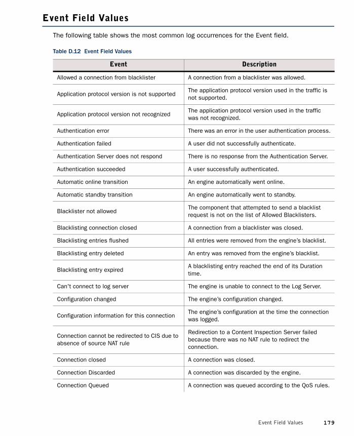
Event Field Values
The following table shows the most common log occurrences for the Event field.
Table D.12 Event Field Values
Event Description
Allowed a connection from blacklister A connection from a blacklister was allowed.
Application protocol version is not supportedThe application protocol version used in the traffic is not supported.
Application protocol version not recognizedThe application protocol version used in the traffic was not recognized.
Authentication error There was an error in the user authentication process.
Authentication failed A user did not successfully authenticate.
Authentication Server does not respond There is no response from the Authentication Server.
Authentication succeeded A user successfully authenticated.
Automatic online transition An engine automatically went online.
Automatic standby transition An engine automatically went to standby.
Blacklister not allowedThe component that attempted to send a blacklist request is not on the list of Allowed Blacklisters.
Blacklisting connection closed A connection from a blacklister was closed.
Blacklisting entries flushed All entries were removed from the engine’s blacklist.
Blacklisting entry deleted An entry was removed from the engine’s blacklist.
Blacklisting entry expiredA blacklisting entry reached the end of its Duration time.
Can't connect to log server The engine is unable to connect to the Log Server.
Configuration changed The engine’s configuration changed.
Configuration information for this connectionThe engine’s configuration at the time the connection was logged.
Connection cannot be redirected to CIS due to absence of source NAT rule
Redirection to a Content Inspection Server failed because there was no NAT rule to redirect the connection.
Connection closed A connection was closed.
Connection Discarded A connection was discarded by the engine.
Connection Queued A connection was queued according to the QoS rules.
179Event Field Values

Connection redirected to Content Inspection Server
A connection was redirected to an external Content Inspection Server.
Connection Refused A connection was refused by the engine.
Connection Terminated A connection was terminated by the engine.
Data connection cannot be redirected to CIS due to absence of source NAT rule
Redirection to a Content Inspection Server failed because there was no NAT rule to redirect the data connection.
Data connection redirected to content inspection server
A data connection was redirected to an external Content Inspection Server.
DHCP message received A DHCP message was received.
DHCP Relay address not configured, reply discarded
A DHCP reply was discarded because no DCHP address is configured for the engine.
DHCP Relay address spoofed, request discarded
A DHCP request was discarded because the DHCP relay address was considered spoofed.
DHCP reply received A DHCP reply was received.
DHCP reply sent A DHCP reply was sent.
DHCP request forwarded A DHCP request was forwarded.
DHCP request received A DHCP request was received.
DHCP request sent A DHCP request was sent.
Dropped AH packet An IPsec AH packet was dropped.
Dropped ESP packet An IPsec ESP packet was dropped.
Error in receiving a new configurationThere was an error when trying to transfer a new configuration to the engine.
Error with Content Inspection ServerThere was an error when attempting to redirect a connection to an external Content Inspection Server.
Failed to allow a related connection to openThe engine failed to open a related connection for a connection that had already been allowed.
Force offline by test failureThe engine was forced offline as the result of an automated test failing.
Going locked offline by commandAn administrator commanded the engine to go to the locked offline state.
Going locked online by commandAn administrator commanded the engine to go to the locked online state.
Going offline by command An administrator commanded the engine to go offline.
Table D.12 Event Field Values (Continued)
Event Description
180 Appendix D Log Fields

Going offline by test failureThe engine went offline as the result of an automated test failing.
Going online by command An administrator commanded the engine to go online.
Going standby by commandAn administrator commanded the engine to go to standby.
Hybrid authentication done Hybrid authentication successfully completed.
Hybrid authentication failed Hybrid authentication failed.
Incomplete connection closedA connection for which the TCP handshake did not complete was closed.
Internal engine error An internal error occurred on the engine.
Internal error An internal error occurred.
Invalid license The engine has an invalid license.
Invalid properties of custom Protocol AgentInvalid options have been configured for a custom Protocol Agent.
IPsec authentication error An error occurred in IPsec authentication.
IPsec client cfg download doneThe configuration for an IPsec VPN Client has finished downloading.
IPsec client cfg download failedAn attempt to download the configuration for an IPsec VPN Client failed.
IPsec client cfg download fromThe configuration for an IPsec VPN Client was downloaded by the client at the source address.
IPsec IKE errorThere was an error in the IKE negotiation for an IPsec VPN.
LDAP Server does not respond An LDAP Server is not responding.
License exceeded A throughput based license was exceeded.
Log spool corruptedThe data in the engine’s log spool partition has become corrupted.
Log spool is becoming full The engine’s log spool partition is becoming full.
New blacklisting entry A new entry was added to the engine’s blacklist.
New configuration successfully installed A new configuration was installed on the engine.
New connection A new connection was allowed through the engine.
New VPN connectionA new connection through an existing VPN tunnel was allowed.
Table D.12 Event Field Values (Continued)
Event Description
181Event Field Values

No space left on device The engine’s hard drive is full.
No suitable NAT rule found No NAT rule matched a connection.
No suitable NAT rule found for related connection
No NAT rule matched a related connection.
Node booted An engine node booted up.
Node down An engine node is down.
Node up An engine node is up.
Oversized DHCP message discarded An excessively large DHCP message was discarded.
Packet Discarded A packet was discarded by the engine.
Packet too long A packet was too long.
Packet too short A packet was too short.
Receive ICMP echo An ICMP echo (ping) was received.
Related ConnectionA related connection was allowed through the engine. For example, an FTP data connection.
Related PacketA related packet was allowed through the engine. For example, ICMP error messages related to an earlier TCP connection.
Requested NAT cannot be done There was an error when applying NAT to the traffic.
Security Policy reload New security policy is loaded on the engine.
Send ICMP echo An ICMP echo (ping) was sent.
Sending DHCP reply failed The engine failed to send a DHCP reply.
Sending DHCP request failed The engine failed to send a DHCP request.
Sending sync messages The engine is sending synchronization messages.
Server pool member went offline A Server Pool member went offline.
Server pool member went online A Server Pool member went online.
SSL Handshake failed An SSL handshake failed.
Starting hybrid authentication Hybrid authentication started.
Starting IKE initiator negotiation IKE initiator negotiation started.
Starting IKE responder negotiation IKE responder negotiation started.
State sync communication failureState synchronization communication between cluster nodes failed.
Table D.12 Event Field Values (Continued)
Event Description
182 Appendix D Log Fields

A successful engine login causes an event that is displayed in the Logs view with the following type of message in the Info Message field: date time login[id]:USERNAME LOGIN on ‘device’. A failed login causes an info message of the following type: date time login[id]:FAILED LOGIN (#) on ‘device’ FOR ‘UNKNOWN’.
State sync configuration changedThe configuration of the synchronization communication between cluster nodes changed.
Unknown DCHP Relay error An unknown error occurred in DHCP relay.
Unrecognized protocol A protocol in the logged traffic was not recognized.
Went locked offline The engine went to the locked offline state.
Went locked online The engine went to the locked online state.
Went offline The engine went offline.
Went online The engine went online.
Went standby The engine went to standby.
Table D.12 Event Field Values (Continued)
Event Description
183Event Field Values

IPsec VPN Log Messages
The tables in this section list the most common IPsec VPN log messages (Facility=IPsec). Some messages can only be seen when the VPN diagnostics are enabled during the VPN negotiations. The messages listed appear in the Information Message fields of logs as information or error messages. The Situation field in some of the logs contains similar messages.
• VPN Notifications• VPN Errors (page 186)• VPN Error Codes (page 189)
VPN NotificationsThe table below lists messages that are seen in the logs as part of normal IPsec VPN operation.
Table D.13 Common IPsec VPN Messages in Normal Operation
Information Message Description
SA traffic selectors local: [...]This message is visible only when IPsec diagnostics are enabled.The first message generated when new VPN negotiations are triggered. Negotiation of a new VPN tunnel follows.
IKE SA proposal [...]This message is visible only when IPsec diagnostics are enabled.Shows the proposal that the initiator in the negotiations sent to the responder (displayed in both roles).
Starting IKE main mode initiator negotiationStarting IKE main mode responder negotiation
The beginning of IKE negotiations (in main mode).Which message is displayed depends on whether the gateway is the initiator or the responder in the negotiation.Repeated negotiations for the same connection are normal in a Multi-Link environment.
IKE Phase-1 initiator done [...]IKE Phase-1 responder done [...]
IKE Phase-1 negotiations were successfully completed, Phase-2 negotiations will begin.Which message is displayed depends on whether the gateway is the initiator or the responder in the negotiation.
IKE Phase-2 initiator done [...]IKE Phase-2 responder done [...]
IKE Phase-2 negotiations were successfully completed. The VPN tunnel is now established and ESP or AH message(s) should appear shortly.Which message is displayed depends on whether the gateway is the initiator or the responder in the negotiation.
Starting Hybrid Authentication Hybrid authentication is started for an IPsec VPN client user.
Hybrid Authentication Done Hybrid authentication succeeded for an IPsec VPN client user.
IKE SA import succeededIPsec SA import succeeded
This message is visible only when IPsec diagnostics are enabled.Synchronization of Phase 1 (IKE) and Phase 2 (IPsec) information between clustered firewall engines was successful.
184 Appendix D Log Fields

ESP [...]AH [...]
Encrypted traffic going through the VPN tunnel. When you enable IPsec diagnostics you may see more of these messages.
Unknown IKE cookie
This message is visible only when IPsec diagnostics are enabled.The other gateway identified an SA that does not exist on this node. If this is a cluster, this message is normal when the SA has been negotiated with a different node and the correct SA is then queried from the other nodes, allowing the connection to continue.This message can also appear if the SA has been deleted, for example, because of a timeout or dead peer detection (DPD).
Sending delete notification [...]Delete notification received [...]
This message is visible only when IPsec diagnostics are enabled.Messages between the gateways forming the tunnel informing the other party that the gateway has removed the settings indicated in the message. As a result, the other gateway also clears the settings, allowing for renegotiations if the tunnel is still needed.
Sending IKE SA delete syncReceiving IKE SA expire/delete sync
This message is visible only when IPsec diagnostics are enabled.Synchronization of SA deletion information between clustered firewall engines.
Initial contact notification received
The gateway at the other end of the tunnel has sent an Initial-Contact message (indicating that it has no knowledge of previous negotiations). If there are old SAs with the gateway, they are deleted at this point (recently negotiated SAs are not, as may be indicated by a further log message). If SAs exist, the notification may indicate that the other end has been cleared, for example, in a reboot.
Table D.13 Common IPsec VPN Messages in Normal Operation (Continued)
Information Message Description
185IPsec VPN Log Messages

VPN ErrorsThe table below lists common errors that indicate problems in an IPsec VPN tunnel. The log messages inform you about the stage of negotiations and then give the actual error message, for example, “IKE Phase-2 error: No proposal chosen”. The table lists only the actual message part without additional variable details such as IP addresses or identifiers.
Table D.14 Common IPsec VPN Errors
Error Message Description
Access group mismatch The connecting VPN client is not authorized.
Authentication failed
One of the parties rejected the authentication credentials or something went wrong during the authentication process. If the problem is not apparent in the available logs, activate diagnostics to generate more verbose logs that give you more information about the next negotiations.
Authentication method mismatch
The authentication method used by the other gateway is not allowed in the configuration of this gateway. Check the settings in the VPN Profile that is selected for this VPN.
Can not get policy [...] No matching connection
May indicate that the gateway has no valid VPN certificate.
Can not get QM policy [...]
Indicates that there is a mismatch in granularity settings between the negotiating gateways.In the McAfee Firewall/VPN, granularity is controlled with the Security Association Granularity setting on the IPsec Settings tab of the VPN Profile.
Could not allocate inbound SPI
Indications that the gateway has run out of memory. The reasons for this may include inappropriate configuration settings (such as using the “SA per host” setting with a very large number of hosts) in addition to other considerations (such as hardware specifications).
Could not create outbound IPsec rule
Could not register outbound SPI
Old outbound SPI entry not found
Out of memory
SA install failed
Session attaching failed
Transform creation failed
Dead peer detection failedIKE peer was found dead [...]
Dead peer detection checks the other gateway periodically when the VPN is established. If no response is received, the VPN tunnel is closed. Indicates that the other gateway is down, unreachable, or considers the VPN tunnel already closed.
186 Appendix D Log Fields

Encapsulation mode mismatchEncapsulation modes (AH and/or ESP) did not match between gateways.
IKE error notify received: [...]This message is visible only when IPsec diagnostics are enabled.The other gateway has sent the error notification that is shown in this message.
IKE negotiation rate-limit reached, discard connection
This message is visible only when IPsec diagnostics are enabled.There is an excessive number of new VPN connection attempts within a short period of time. This mechanism is meant to protect the firewall from certain types of denial-of-service attacks.
Invalid argument Generic error. Check the other log messages for more useful information. If the problem is not apparent in the available logs, activate diagnostics to generate more verbose logs that give you more information about the next negotiations.
Invalid syntax
IPsec SA proposal not accepted
This message is visible only when IPsec diagnostics are enabled.The VPN gateway at the other end of the tunnel sent a proposal that the McAfee Firewall/VPN gateway could not accept. This message includes information about the rejected proposal and a further log message should contain information on the McAfee Firewall/VPN’s local proposal.
NAT-T is not allowed for this peer
This message is visible only when IPsec diagnostics are enabled.NAT-T was requested by the other gateway but it is not allowed in the configuration of the gateway that sends this message.
No proposal chosenIKE negotiations failed. If the problem is not apparent in the available logs, activate diagnostics to generate more verbose logs that give you more information about the next negotiations.
Payload malformed [...]Most likely due to a mismatch in preshared keys between the initiator and the responder. May also be due to corruption of packets in transit.
Peer IP address mismatchThe IP address of the other gateway uses is not configured as a VPN gateway end-point on this gateway.
Proposal did not match policyThere is a mismatch in the configurations of the two negotiating parties.
Remote address not allowed
A VPN client is trying to use an IP address that is out of the allowed address range. Make sure all valid IP addresses are actually included in the range of allowed addresses in the Internal VPN Gateway properties and check the DHCP server configuration.
Table D.14 Common IPsec VPN Errors (Continued)
Error Message Description
187IPsec VPN Log Messages

Remote ID mismatch The IKE Phase 1 ID defined for the external VPN gateway in the SMC is different from the ID with which the gateway actually identified itself. The ID and its type are set for each tunnel End-Point in the properties of the external Gateway. Note that if an IP address is used as identity, the IP address used as the identity may be different from the IP address used for communications.
Remote identity [...] used in IKE negotiation doesn’t match to policy [...]
SA unusableUsually means that an SA is being deleted when some new traffic arrives to use the tunnel.
Sending error notify: [...]This message is visible only when IPsec diagnostics are enabled.Negotiations have failed and the McAfee Firewall/VPN is sending the error notification that is shown in this message to the other gateway.
SPD doesn’t allow connection [...]
Most likely indicates that the Site definitions do not match the IP addresses used. Check the addresses included under the Sites for both Gateways, and also that the translated addresses are included under the Site, if NAT is used for communications inside the VPN.
Timed outIndicates connection problems or that the other end has deleted the SA that the McAfee Firewall/VPN is using in the negotiation. Check the logs at the other end to see if the connection makes it through.
Traffic selector mismatchThere is a mismatch in the configurations of the two negotiating parties. You must define a matching pair for all settings; double-check all settings at both ends.
Tunnel policy mismatch [...]This message is visible only when IPsec diagnostics are enabled.Usually indicates IKE negotiations failed because of a mismatch in the configurations of the two negotiating parties.
Tunnel selection failed
An Access rule matched this connection, but the traffic could not be sent across the VPN. Most likely, this is due to the (possibly NATed) source or destination IP address not being included in the local or remote gateway’s Site as required. This message also appears if a connection that is not intended for the VPN matches the VPN rule (note that inbound cleartext traffic can be allowed from the same addresses as tunneled traffic with the Apply action in the VPN rule).
Tunnel type mismatch [...]
This message is visible only when IPsec diagnostics are enabled.Only gateway-to-gateway VPN or client-to-gateway VPN is configured, but the connecting device is of the other type. For example, a VPN client tried to connect, but VPN client access is not configured (correctly) on the gateway.
Table D.14 Common IPsec VPN Errors (Continued)
Error Message Description
188 Appendix D Log Fields

VPN Error CodesUnder some conditions, multiple IPsec VPN errors may be detected simultaneously and combined in a single log message. The most significant error is shown as text, and the other detected errors are indicated using a combined (with bitwise OR) hexadecimal error code.
Example IKE Phase-1 Initiator error: Proposal did not match policy (100002).Here, the hexadecimal codes00100000 for “Proposal did not match policy” and00000002 for “Peer IP address mismatch”) produces the code00100002 = 100002.
The table below lists codes that are valid for engine software versions 5.0 and above.
Table D.15 Hexadecimal Error Codes in VPN Log Messages
Hex Code Error Message
00000020 Access group mismatch
00008000 Authentication method mismatch
00020000 Encapsulation mode mismatch
00000002 Peer IP address mismatch
00100000 Proposal did not match policy
00400000 Remote address not allowed
00000040 Traffic selector mismatch (local)
00000080 Traffic selector mismatch (remote)
00200000 Tunnel type mismatch
00000200 Remote ID mismatch
000001000000000400000001
Internal configuration-related problems. See the other messages to troubleshoot.
189IPsec VPN Log Messages

Audit Entry Types
The following table explains the audit entry types.
Table D.16 Audit Entry Types
Type Definition
audit.start The Audit Service started.
audit.stop The Audit Service stopped.
stonegate.admin.attachLog.authserverA Log Server was associated with an Authentication Server.
stonegate.admin.attachLog.mgtserverA Log Server was associated with a Management Server.
stonegate.admin.attachLog.webportalserver A Log Server was associated with a Web Portal Server.
stonegate.admin.authenticationkey.changeThe authentication key of an API Client element was changed.
stonegate.admin.changeIp.mgtserver The Management Server IP address changed.
stonegate.admin.changeMgtIp.authserver The Authentication Server IP address changed.
stonegate.admin.changeMgtIp.logserver The Log Server IP address changed.
stonegate.admin.changeMgtIp.webportalserver
The Web Portal Server IP address changed.
stonegate.admin.create A superuser administrator was created.
stonegate.admin.defaultfiltercolors.changeThe default filter colors for an administrator were changed.
stonegate.admin.delete An administrator was deleted.
stonegate.admin.disabled An administrator was disabled.
stonegate.admin.enabled An administrator was enabled.
stonegate.admin.login An administrator logged in to the Management Server.
stonegate.admin.logoutAn administrator logged out from the Management Server.
stonegate.admin.password.change An administrator’s password changed.
stonegate.admin.pdfpagesetup.change Changes were made to the setup of PDF pages
stonegate.admin.permission.change Permissions for an administrator changed.
stonegate.admin.sendmessage.disabled The sending of messages was disabled.
stonegate.admin.sendmessage.enabled The sending of messages was enabled.
190 Appendix D Log Fields

stonegate.alert.ack.policyAn acknowledgement about an alert related to a policy was sent.
stonegate.alert.ack.userAn acknowledgement about an alert related to a user was sent.
stonegate.alert.policy.uploadA policy was uploaded to the Alert Server (successfully or not).
stonegate.alert.test A test alert was sent.
stonegate.archive.export An administrator ran a script to export an archive.
stonegate.audit.archive.create An audit data archive was created.
stonegate.audit.archive.delete An audit data archive was deleted.
stonegate.audit.archive.restore An audit data archive was restored.
stonegate.authentication.apply.endAn Apply Configuration on an SMC Authentication Server completed (successfully or not).
stonegate.authentication.apply.startAn Apply Configuration on an SMC Authentication Server started.
stonegate.authentication.service.startThe Authentication Service started on the Authentication Server.
stonegate.authentication.service.stopThe Authentication Service stopped on the Authentication Server.
stonegate.authentication.user.add A user on the Authentication Server was added.
stonegate.authentication.user.delete A user on the Authentication Server was deleted.
stonegate.authentication.user.update A user on the Authentication Server was updated.
stonegate.backup.createA backup was created on the server where the audit entry was created.
stonegate.backup.deleteA backup was deleted from the server where the audit entry was created.
stonegate.backup.restoreA backup was restored io the server where the audit entry was created.
stonegate.ca.certificate.downloadAn Internal Certificate Authority was uploaded to an engine.
stonegate.ca.certificate.stoptrustingAn engine was commanded to stop trusting an Internal Certificate Authority.
stonegate.database.migrateThe database of the server where the audit entry was created was migrated.
Table D.16 Audit Entry Types (Continued)
Type Definition
191Audit Entry Types

stonegate.database.password.changeThe database password of the server where the audit entry was created was changed.
stonegate.diff.start Comparison of two snapshots started.
stonegate.diff.stop Comparison of two snapshots ended.
stonegate.directarchive.start The direct archive option was set to ON.
stonegate.directarchive.stop The direct archive option was set to OFF.
stonegate.engine.initial.contactAn engine performed initial contact to the Management Server.
stonegate.engine.initial.generate The initial configuration was generated for an engine.
stonegate.engine.time.adjust The engine time was adjusted.
stonegate.engine.upgrade.end An engine upgrade ended.
stonegate.engine.upgrade.start An engine upgrade started.
stonegate.export.start An export operation started.
stonegate.export.stop An export operation ended.
stonegate.firewall.connections.terminate A connection was terminated.
stonegate.firewall.diagnostic Diagnostic mode was selected for a Firewall.
stonegate.firewall.disable.userdatabase The user database was disabled.
stonegate.firewall.enable.userdatabase The user database was enabled.
stonegate.firewall.policy.uploadA policy was uploaded to a Firewall (successfully or not).
stonegate.firewall.reset.database The user database was reset.
stonegate.ha.syncA Management Server retrieved a full database backup in a high-availability environment.
stonegate.https.certificate.request An HTTPS certificate was requested from a Firewall.
stonegate.import.start An import operation started.
stonegate.import.stop An import operation ended.
stonegate.incident.attachment.add An attachment was added to an Incident Case.
stonegate.incident.attachment.remove An attachment was removed from an Incident Case.
stonegate.incident.attachment.update An attachment for an Incident Case was updated.
stonegate.incident.player.add A player was added to an Incident Case.
Table D.16 Audit Entry Types (Continued)
Type Definition
192 Appendix D Log Fields

stonegate.incident.player.remove A player was removed from an Incident Case.
stonegate.incident.player.update A player attached to an Incident Case was updated.
stonegate.installserver.logAn initial configuration for an engine was uploaded to the Installation Server or an engine sent logs to the Installation Server in plug-and-play configuration.
stonegate.installserver.traceAn engine sent traces to the Installation Server in plug-and-play configuration.
stonegate.ips.diagnostic Diagnostic mode was selected for an IPS engine.
stonegate.ips.policy.uploadA policy was uploaded to an IPS engine (successfully or not).
stonegate.ips.time.adjust The IPS engine time was adjusted.
stonegate.ips.upgrade.end An IPS engine node upgrade ended.
stonegate.ips.upgrade.start An IP engine node upgrade was started.
stonegate.license.activate A license file or a license component was activated.
stonegate.license.delete A license component was deleted.
stonegate.license.install A license was installed.
stonegate.log.browse An administrator performed a query in the Logs view.
stonegate.logdatamanager.abort A scheduled task was aborted in the Log Server.
stonegate.logdatamanager.complete A scheduled task was completed in the Log Server.
stonegate.logdatamanager.create A scheduled task was created in the Log Server.
stonegate.logdatamanager.delete A scheduled task was deleted in the Log Server.
stonegate.logdatamanager.modify A scheduled task was modified in the Log Server.
stonegate.logdatamanager.start A user manually started a task.
stonegate.logpruningfilter.apply A pruning filter was applied to the Log Server.
stonegate.logpruningfilter.delete A pruning filter was deleted from the Log Server.
stonegate.logpruningfilter.refreshFollowing a Log Server re-logging to the Management Server, all the pruning filters were retrieved on the Management Server and re-applied.
stonegate.logreception.start The log reception process started.
stonegate.logreception.stop The log reception process ended.
stonegate.logserver.certify The Log Server was certified.
Table D.16 Audit Entry Types (Continued)
Type Definition
193Audit Entry Types
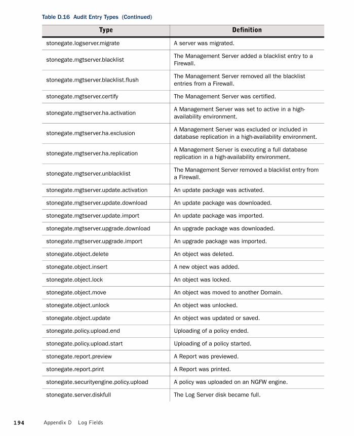
stonegate.logserver.migrate A server was migrated.
stonegate.mgtserver.blacklistThe Management Server added a blacklist entry to a Firewall.
stonegate.mgtserver.blacklist.flushThe Management Server removed all the blacklist entries from a Firewall.
stonegate.mgtserver.certify The Management Server was certified.
stonegate.mgtserver.ha.activationA Management Server was set to active in a high-availability environment.
stonegate.mgtserver.ha.exclusionA Management Server was excluded or included in database replication in a high-availability environment.
stonegate.mgtserver.ha.replicationA Management Server is executing a full database replication in a high-availability environment.
stonegate.mgtserver.unblacklistThe Management Server removed a blacklist entry from a Firewall.
stonegate.mgtserver.update.activation An update package was activated.
stonegate.mgtserver.update.download An update package was downloaded.
stonegate.mgtserver.update.import An update package was imported.
stonegate.mgtserver.upgrade.download An upgrade package was downloaded.
stonegate.mgtserver.upgrade.import An upgrade package was imported.
stonegate.object.delete An object was deleted.
stonegate.object.insert A new object was added.
stonegate.object.lock An object was locked.
stonegate.object.move An object was moved to another Domain.
stonegate.object.unlock An object was unlocked.
stonegate.object.update An object was updated or saved.
stonegate.policy.upload.end Uploading of a policy ended.
stonegate.policy.upload.start Uploading of a policy started.
stonegate.report.preview A Report was previewed.
stonegate.report.print A Report was printed.
stonegate.securityengine.policy.upload A policy was uploaded on an NGFW engine.
stonegate.server.diskfull The Log Server disk became full.
Table D.16 Audit Entry Types (Continued)
Type Definition
194 Appendix D Log Fields

stonegate.server.migrate A server was migrated.
stonegate.server.sginfo An sgInfo package was created.
stonegate.server.start The Log Server was started.
stonegate.server.stop The Log Server was stopped.
stonegate.sslvpn.policy.upload A policy was uploaded on an SSL VPN gateway.
stonegate.vpn.certificate.download A client downloaded a VPN certificate.
stonegate.vpn.certificate.request A VPN certificate was requested.
stonegate.vpn.certificate.sign A VPN certificate was signed.
stonegate.vpn.configuration.export A policy was uploaded on an SSL VPN gateway.
stonegate.vpn.gateway.remove A VPN gateway was removed.
stonegate.vpn.psk.create A pre-shared key was added in a VPN tunnel.
stonegate.vpn.psk.delete A pre-shared key was removed from a VPN tunnel.
stonegate.vpn.psk.modify A pre-shared key was modified in a VPN tunnel.
stonegate.vpn.site.remove A VPN site was removed.
stonegate.webportal.log.browseThe filtering or the data type in the Web Portal Log Browser was changed.
stonegate.webportal.log.pdfThe Log Details were viewed as a PDF from the Web Portal Log Browser.
stonegate.webportal.report.pdf A Report was viewed as a PDF from the Web Portal.
stonegate.webportal.report.preview A Report was previewed as HTML from the Web Portal.
Table D.16 Audit Entry Types (Continued)
Type Definition
195Audit Entry Types

Syslog Entries
The following table presents the categories for messages that appear in log entries sent to an external syslog server.
Table D.17 Syslog Entries
Value
Clock daemon for BSD systems
Clock daemon for System V systems
File transfer protocol
Kernel messages
Line printer subsystem
Mail system
Messages generated internally by syslogd
Network news subsystem
Network time protocol
Random user-level messages
Security/authorization messages
Security/authorization messages (private)
System daemons
UUCP subsystem
196 Appendix D Log Fields

Log Fields Controlled by the Additional Payload Option
The following table presents the log fields that may be logged when the Additional Payload option is selected in an Inspection rule’s Logging options.
Table D.18 Additional Payload Log Fields
Value
DNS qname
FTP command
FTP reply
FTP server banner
HTTP header
HTTP header name
HTTP request URI
HTTP request method
HTTP request version
ICMP field datagram reference
Imf encoded word
Imf header field
Imf token
SMTP command
SMTP misplaced command
SMTP recipient
SMTP reply
SMTP reverse path
SMTP server banner
197Log Fields Controlled by the Additional Payload Option

Connection States
The following states are used both in the State column in the Connections view and (in part) in the Logs view in conjunction with info messages or logs on the closing of connections. They reflect the standard states regarding the initiation and termination of TCP connections as seen by the firewall in the transmissions. The table below lists the possible states.
Table D.19 Connection States
State Description
CP established NGFW cluster protocol packet is recognized.
ICMP echo Ping reply is expected.
ICMP reply wait Other ICMP request or reply types.
Invalid The communication has violated the protocol.
IPsec established IPsec tunnel packet is recognized.
New New connection is being opened.
Related New connection related to an existing one is expected soon.
Remove Connection cannot be physically removed yet.
Remove soonExpecting to still see some packets (multiple reset packet), so delaying the removal for a few seconds. Eliminates unnecessary packet filtering and possible logging of dropped packets.
TCP close wait One end of the connection waits for the FIN packet (passive close).
TCP close wait ackWaiting for ACK for the FIN before going to close wait status (passive close).
TCP closing Closing packet (FIN) sent by one end of the connection (simultaneous).
TCP closing ack Waiting for ACK for the FIN before going to closing status (active close).
TCP established Normal status of TCP connections for data transfer.
TCP fin wait 1One end of the connection waits for sending the FIN packet (active close).
TCP fin wait 2 One end of the connection waits for receiving ACK packet.
TCP last ack One end of the connection sent a FIN packet (passive close).
TCP last ack wait Waiting for the FIN packet to be acknowledged.
TCP syn ack seenSecond phase of the TCP three-way handshake, the server has replied to client sent SYN with SYN+ACK, next status will be established.
TCP syn fin seen T/TCP (Transactional TCP) connection, RFC 1644.
TCP syn return Received simultaneous SYN from the other end (simultaneous open).
198 Appendix D Log Fields

TCP syn seen Very first packet sent by one end of the connection.
TCP time wait One end of the connection acknowledged closing packet (FIN).
TCP time wait ackWaiting for ACK for the FIN status before going to time wait status (active close).
UDP established UDP connection is recognized.
Unknown established Connection from other transport level protocol.
Table D.19 Connection States (Continued)
State Description
199Connection States

200 Appendix D Log Fields

APPENDIX E
SCHEMA UPDATES FOR EXTERNAL LDAP SERVERS
This section lists the SMC-specific LDAP classes and attributes that you add to the schema of external LDAP servers.
The SMC-specific attribute and class names start with “sg”. The classes are listed in the table below.
The SMC-specific attributes are listed in the table below.
Table E.1 SMC-Specific LDAP Classes
Class Description
sggroup SMC user group
sguser SMC user account
Table E.2 SMC-Specific LDAP Attributes
Attribute Related Classes Description
sgactivation sguser Activation date for the user account.
sgauth sggroup, sguser Authentication service for the user or group.
sgdelay sggroup, sguserNumber of days the user account is valid after the activation.
sgexpiration sguserLast day when the user account is valid and the user can log in.
sggrouptype sggroupIndicates the type of the group: a subtree or discrete group.
sgmember sggroupThe Distinguished Name (DN) for the user member of this group.
201

In addition to updating the directory schema, there may be some server-specific requirements. For Netscape and OpenLDAP version 1.2.11 servers, you must configure the following lines to the LDAP server’s slapd.conf configuration file after stopping the LDAP service:
For OpenLDAP server versions 2.0 and later, you must configure the following lines to the LDAP server’s slapd.conf configuration file after stopping the LDAP service:
sgpassword sguser MD5 message digest hash of the user password.
sgpresharedkey sguser IPsec PreSharedKey for the user account.
sgsubjectaltnames sguserIPsec certificate SubjectAltNames for the user account.
sgvirtualip sggroup, sguser Virtual IP allocation allowed for the user.
Illustration E.1 Additional Configuration for OpenLDAP v1.2.11 and Netscape Server
include /etc/openldap/slapd.at.confinclude /etc/openldap/slapd.oc.confinclude /etc/openldap/sg-schema.confschemacheck on
Illustration E.2 Additional Configuration for OpenLDAP version 2.0 or later
include /etc/openldap/schema/core.schemainclude /etc/openldap/schema/cosine.schemainclude /etc/openldap/schema/inetorgperson.schemainclude /etc/openldap/schema/sg-v3.schema
Table E.2 SMC-Specific LDAP Attributes (Continued)
Attribute Related Classes Description
202 Appendix E Schema Updates for External LDAP Servers
GLOSSARY
AAccess Control List
A list of Elements that can be used to define the Elements that an Administrators with restricted permissions can access. See also Administrator Role and Granted Element.
Action
What the engine should do with a packet that matches the criteria for a particular rule in the Security Policy.
Action Option
Additional action-specific selections that affect how the traffic is handled set in the Action cell in rules.
Active Management Server
The Management Server that currently has control of all Domains in an environment that has at least one Additional Management Server.
Additional Log Server
A Log Server defined as a backup channel for components that primarily send their logs to some other Log Server.
Additional Management Server
A redundant Management Server that replicates the configuration data from the Active Management Server under normal conditions so that the services offered by the Management Server can be used without interruption if components fail or are otherwise unavailable.
Address Range
A Network Element that defines a range of IP addresses. Use to avoid having to repeatedly type in the same IP addresses when defining address ranges that do not correspond to whole networks.
Address Resolution Protocol (ARP)
An Internet standard (RFC 826) protocol used to associate IP addresses with the media hardware address of a network interface card on a local area network (LAN).
Administrator
An Element that defines the details of a single person that is allowed to log on to the SMC using the Management Client. If used as a general term, Web Portal Users are also considered as administrators.
203
Administrator Role
An Element that defines which actions an Administrator with restricted permissions is allowed to take. See also Granted Element and Permission Level.
Aggressive Mode
The authentication of two IPsec end-points with only three messages, as opposed to Main Mode’s six. Aggressive mode also does not provide PFS support, and SA negotiation is limited. See Main Mode (page 219). See also Security Association (SA) (page 225).
AH (Authentication Header)
See Authentication Header (AH) (page 206).
Alert Chain
A list of rules defining which Alert Channels are used, and in which order, when an alert entry is directed to the Alert Chain from an Alert Policy to be escalated out from the SMC. See also Alert Escalation.
Alert Channel
A method of sending alerts out from the Log Server. You can send alerts via SMTP (e-mail), SNMP, SMS text messages, or some other action you define in a custom script. Alert Channels are defined in the Log Server’s properties, after which they can be used in Alert Chains.
Alert Element
An Element that gives the name and description to an Alert Event. The Alert element can be used as a matching criteria in the rules of an Alert Policy.
Alert Entry
A log message with an alert status that has been raised based on some Situation (which you can see in the Logs View). Alert entries trigger Alert Escalation.
Alert Escalation
Sending alerts out from the SMC to administrators through Alert Channels (such as e-mail) according to a predefined Alert Chain until the original Alert Entry is acknowledged by some administrator in the Logs View.
Alert Event
A pattern in traffic or a problem in the system’s operation that matches some Situation used in a policy or internally in the system, and triggers an Alert Entry.
Alert Policy
A list of rules defining if an Alert Entry is escalated and which Alert Chain is used for escalating which type of alert entries. See also Alert Escalation.
Alias
An Element that can be used to represent other network elements in configurations. It differs from a group element in that it does not represent all the elements at once: the value it takes in a configuration can be different on each engine where it is used.
204 Glossary

Allow Action
An Action parameter that allows a connection matching that rule to pass through the Firewall to its destination.
Analyzer
1) A legacy IPS device that analyzes the log information from Sensors according to its policy to find patterns, so that separate log entries can be combined together. See also Log Server, Security Engine.
2) The legacy Element that represents an Analyzer device in the SMC.
Antispoofing
Technique used to protect against malicious packages whose IP header information has been altered. See also IP Spoofing (page 216).
Application
A category of Tags for Situations. Meant for grouping Situations that detect known vulnerabilities in a particular software application.
Application Layer Gateway; Application Level Firewall
A firewall system, or gateway, in which packets are examined based on the application protocol being used (e.g., telnet, FTP, SMTP). Proxies for each application-level service are installed on the gateway, and are often configured to relay a conversation between two systems. That is, a packet’s destination is the gateway, which then establishes a separate connection to the other system to complete the connection.
Apply VPN Action
An Action in the Firewall Policy that directs traffic from protected local networks into the Virtual Private Network (VPN) tunnel and allows traffic that arrives through a VPN, but does not match non-VPN traffic from outside networks into the protected networks. See also Enforce VPN Action (page 212).
ARP (Address Resolution Protocol)
See Address Resolution Protocol (ARP) (page 203).
Asymmetric Encryption
A cryptographic technology that uses a pair of keys. The message is encrypted with the public half of a pair and can then be decrypted only with the matching private half of the key pair. Public key technology can be used to create digital signatures and deal with key management issues. Also referred to as public key encryption. See also Symmetric Encryption (page 228) and Public-key Cryptography (page 223).
Auditing
An SMC feature that logs administrators’ actions and allows administrators with unrestricted permissions to view and manage these logs to keep track of system changes.
Authentication
The process of proving that someone or something is who or what they claim to be. For example, typing a simple username-password combination is a form of authentication.
205Glossary

Authentication Header (AH)
A security protocol supported by the IPsec protocol to enhance traffic security. It enables the authentication and integrity of data against packet corruption or tampering. AH protocol can use SHA-1 or MD5 to generate a hash signature based on a secret component from the SA, the packet payload and some parts of the packet header. See also Security Association (SA) (page 225).
Authentication Server
A component of the Security Management Center (SMC) that provides authentication services for end-user and Administrator logins.
Authentication Token/Authenticator
A portable device for authenticating a user. Authentication tokens typically operate by challenge/response, time-based code sequences, or other techniques. One of the most commonly used tokens is the RSA SecurID card.
Authorization
The process of giving someone or something permission to do or have something. Usually related to authentication; once a user has authenticated (proved who they are), they are authorized (given permission) to perform certain actions.
BBalancing Mode
A Security Engine cluster mode that attempts to divide the traffic as equally as possible between the online engines participating in the cluster. Confer to Standby Mode (page 228).
Bandwidth Management
The process of determining and enforcing bandwidth limits and guarantees for different types of traffic either together with Traffic Prioritization or on its own. Also see QoS Class (page 223) and QoS Policy (page 223).
Blacklisting
1) The process of blocking unwanted network traffic either manually or automatically.
2) Persistently blocking access to certain URLs manually.
Bookmark
A stored link to a view or layout in the Management Client.
Bookmark Folder
A folder in the toolbar of the Management Client for storing and sharing Bookmarks.
Border Routing
Routing of connections between different autonomous systems.
BrightCloud
A URL Filtering categorization service that provides categories for malicious sites as well as several categories for different types of non-malicious content that may be considered objectionable.
206 Glossary

Buffer Overflow
When a program’s data in the memory of a computer exceeds the space reserved for it (the buffer), data may in some circumstances be written on other parts of the memory area. Attackers may use buffer overflows to execute harmful program code on a remote system.
Bugtraq
A mailing list for discussing network security related issues, such as vulnerabilities.
Bulk Encryption Algorithm
Describes symmetric encryption algorithms which operate on fixed-size blocks of plaintext and generates a block of ciphertext for each.
CCA
See Certificate Authority (CA) (page 207).
CAN
A candidate for a CVE entry.
Capture Interface
An IPS Engine or Layer 2 Firewall interface that can listen to traffic passing in the network, but which is not used for routing traffic through the engine. See also Inline Interface.
Category
A way of organizing elements and policies to display a specific subset at a time when configuring a large SMC environment in the Management Client to make it easier to find the relevant elements. For example, a Managed Service Provider (MSP) who manages networks of several different customers can add a customer-specific category to each element and policy to be able to view one customer’s elements and policies at a time.
Certificate
Electronic identification of a user or device. Certificates prove the user or device is who or what they claim to be. This is done through using public/private key pairs and digital signatures. Certificates are used in the SMC for authenticating communications between the SMC components and for Virtual Private Network (VPN) authentication. Digital certificates are granted and verified by a Certificate Authority (CA), such as the internal CA included in the Management Server.
Certificate Authority (CA)
A trusted third-party organization or company that issues digital certificates, used to create digital signatures and public-private key pairs. The role of the CA in this process is to guarantee that the individual granted the unique certificate is, in fact, who he or she claims to be.
Challenge/Response
An authentication technique whereby a server sends an unpredictable challenge to the user, who computes a response using some form of authentication token, which can be an authenticator, or pre-shared keys used to encrypt random data.
207Glossary

Checksum
A one-way function applied to a file to produce a unique “fingerprint” of the file for later reference. File tampering can then be discovered by verifying the checksum value in the future.
CIS
See Content Inspection Server (CIS) (page 209).
Client
In a client-server architecture, a client is usually an application running on a computer or a workstation that uses services provided by a Server.
Client Protection Certificate Authority
Contains the credentials that the engine uses to sign replacement server-side certificates the engine creates and presents to clients when inspecting the clients’ HTTPS connections with external servers. Also see Server Credentials (page 226).
Client-to-Gateway VPN
A Virtual Private Network (VPN) between a software client and a VPN Gateway. Allows connecting mobile and home office workers safely to corporate resources using a secure (authenticated and encrypted) connection through insecure networks.
Cluster
A group of devices, or nodes, that share a given work load. In the SMC, you can cluster Firewalls, IPS engines, and Layer 2 Firewalls to share the load and provide redundancy, allowing, for example, scheduled maintenance that takes one node out of service without interrupting services to the users.
Cluster Mode
Determines if all members of a cluster participate to traffic processing at all times (Balancing Mode) or if other members remain inactive until a traffic-processing member stops processing traffic (Standby Mode).
Cluster Virtual IP Address (CVI)
An IP and MAC address shared by all nodes in a cluster, which are used by every node in a cluster for communication. These interfaces give the cluster a single identity on the network, reducing the complexity of routing and network design. CVIs handle the traffic directed to the Firewall for inspection in Firewall Clusters.
Combined Sensor-Analyzer
1) A legacy IPS device that has both Sensor and Analyzer engines running simultaneously on the same hardware.
2) The legacy Element that represents a Combined Sensor-Analyzer device in the SMC.
See also IPS Engine.
Connection Tracking
The set of data maintained for a connection. Used for relating incoming packets to existing connections. Connection tracking information also includes information necessary for NAT (Network Address Translation), Load Balanced Routing, and Protocol Agents. May also contain accounting information.
208 Glossary
Contact Address
The IP address that is needed to contact a device performing a function in the SMC when there is NAT (Network Address Translation) being performed in between the two devices and thus the actual IP address assigned to the network interface cannot be used directly.
Content Inspection Server (CIS)
A server that performs detailed examination of a connection’s data and assists in the determination to allow or discard packets. Common examples include virus scanning or filtering of web URLs. Also known as content screening.
Continue Action
A policy parameter that sets default values to those used in the rule. The defaults are used in all subsequent rules except where specifically overridden until some other rule with the Continue action changes the values or the policy ends.
Context
An Element that is added to a Situation to define what the Situation should match. Provides a framework for defining parameters, which are most entered as a regular expression, or through a set of fields and options that the administrators adjust.
Correlation Situation
A Situation that defines the patterns that the Log Server and/or the Security Engines look for when it examines event data produced by engines.
CRL Server
A server that maintains a Certificate Revocation List (CRL), which can be used in Authentication to check if the certificate has been cancelled.
Custom Alert
An Alert Element that is defined by an SMC administrator, as opposed to a ready-made Default Element created by the SMC.
CVE
A dictionary that provides common names for publicly known information security vulnerabilities and exposures and thus a standardized description for each vulnerability that links the vulnerability information of different tools and databases.
CVI
See Cluster Virtual IP Address (CVI) (page 208).
209Glossary

DDefault Element
An Element that is present in the SMC at installation, or is added to the SMC during an upgrade or from a Dynamic Update (Package). Default elements cannot be modified or deleted by administrators, but they may be modified or deleted by dynamic update packages or upgrades.
Defragmentation
The process by which a large block of data is broken up into smaller pieces (datagrams), so that it can be packaged and transmitted by the underlying network technology (Fragmentation). Once the smaller pieces arrive at their destination, the datagrams are reassembled into the larger block of data (defragmentation).
DHCP (Dynamic Host Configuration Protocol)
A protocol for dynamically assigning IP addresses and other network information to an interface, based on BOOTP. A device on a network with no network information can broadcast a request for an IP address, subnet mask, default gateway and other information from a DHCP server on that same network. DHCP is defined in RFC 2131.
Diagram
An Element that contains one or more network diagrams created using the Diagram Editor.
Digital Certificate
See Certificate (page 207).
Discard Action
An Action parameter that stops all connections matching to the rule without sending any notification to the connecting host. Confer to Refuse Action (page 224).
Dispatch Clustering
See Packet Dispatch (page 221).
DMZ Network
A DMZ (DeMilitarized Zone Network) is a network separate from both internal and external networks, and connected through a gateway. Often used for isolating bastion hosts or publicly available machines, e.g., mail and HTTP servers are typically located on a DMZ network. Sometimes also referred to as a screened subnetwork.
DNS Spoofing
An attack method whereby the DNS name of a system is assumed by a malicious system, either by corrupting the name service cache of a victim, or by compromising a domain name server for a valid domain. The victim system is then directed to the malicious system instead of the original server.
Domain
Domains are administrative boundaries that allow you to separate the configuration details and other information in the SMC for the purpose of limiting administrator access.
210 Glossary

DoS Attack (Denial of Service)
An attack with the objective of causing enough disruption in a computer system that its usability to legitimate users suffers. For example, and attacker may target a website so that it becomes overloaded, and slows down so much that it becomes unusable for people wishing to view it.
DSCP (DiffServ Code Point)
The Differentiated Services (DiffServ) Type of Service (ToS Flag) field added to packets in the network.
DSCP Mark
A field in QoS Policy rules that writes a particular DSCP (DiffServ Code Point) marker to the packets, if the QoS Policy is applied on the interface the packets use to exit the Firewall.
DSCP Match
A field in QoS Policy rules that assigns the QoS Class specified in the rule to incoming packets that have a specific DSCP (DiffServ Code Point) marker set, if the QoS Policy is applied on the interface the packets use to enter of the Firewall.
Dynamic IP address
An IP address that is assigned by using the DHCP (Dynamic Host Configuration Protocol).
Dynamic NAT
A way to translate network addresses, where for each original address, a translated address and possibly a port are selected dynamically from a predefined pool.
Dynamic Update (Package)
A file supplied by McAfee that provides updates to Default Elements and policies, most importantly to the Situation and Vulnerability information that is used for traffic inspection in Inspection Rules.
EElement
An SMC object that represents the equipment in your physical networks or some area or concept of configuration. Elements may, for example, represent a single device such as a server, a range of IP addresses, or some configuration aid in the SMC, such as a Category. See also Network Element (page 220).
Encryption
Used for data security, encryption translates any data into a secret code. Public-key encryption and symmetric encryption are the main types of encryption. Decrypting ciphertext (encrypted data) into plaintext requires access to a secret key.
Encryption Domain
Networks that are defined to be behind a certain VPN gateway in a Virtual Private Network (VPN) configuration.
211Glossary

Encryption Key
The data that is used to convert plaintext to ciphertext. In symmetric algorithms, the same key is the decryption key as well. In public key algorithms, a different, but related key is used to convert the ciphertext back into plaintext.
Encryption Policy
Settings that define which encryption and authentication methods are used to establish a Virtual Private Network (VPN).
Enforce VPN Action
A Firewall Action parameter that directs traffic from protected local networks into the Virtual Private Network (VPN) tunnel and allows traffic that arrives through a VPN, and drops any non-VPN traffic from external networks to the local network that matches the rule. See also Apply VPN Action (page 205).
Ethernet Rules
A set of rules in the IPS Policy that define which Ethernet traffic is allowed or discarded by a Sensor in Transparent Access Control Mode.
Expression
An Element that can be used to accurately define a whole complex set of elements by including and excluding elements using logical expressions.
External Gateway
Any VPN Gateway that is managed by a different Management Server than the one on which the Virtual Private Network (VPN) is being configured.
FFilter
A description of log fields and their values combined together using operators for the purpose of sorting in or out log, alert, and audit entries. Used, for example, to filter out logs from the display in the Logs View so that those entries that are interesting at the moment can be found more easily.
Firewall
1) An Element that represents the firewall device in the SMC. Either a Single Firewall or a Firewall Cluster.
2) The device running the Next Generation Firewall (NGFW) engine software in the Firewall/VPN role.
Firewall Cluster
A Group of two or more Firewall Engines that work together as if they were a single unit.
Firewall Engine
The device that runs the Next Generation Firewall (NGFW) engine software in the Firewall/VPN role. This can be a standard server, an engine installed on a virtualization platform, or a McAfee NGFW appliance. Represented by a Firewall Node in the Management Client.
212 Glossary

Firewall Node
An individual Firewall Engine in the Management Client, representing a device that runs the Next Generation Firewall (NGFW) engine software in the Firewall/VPN role as part of a Firewall Cluster or a Single Firewall.
Forward Action
A Firewall Action parameter that directs traffic from protected local networks or from a Virtual Private Network (VPN) tunnel into another VPN tunnel.
Fragmentation
The process by which a large block of data is broken up into smaller pieces (datagrams), so that it can be packaged and transmitted by the underlying network technology (fragmentation). Once the smaller pieces arrive at their destination, the datagrams are reassembled into the larger block of data (Defragmentation).
GGateway
A device that provides VPN access for other devices.
Gateway Certificate
A Certificate used for authenticating a Gateway to other Gateways and VPN Clients in a VPN.
Gateway Profile
An element that defines a set of VPN-related capabilities that a VPN Gateway supports.
Gateway Settings
An element that contains general settings for McAfee Firewall/VPN engines related to VPN performance.
Gateway-to-Gateway VPN
In the SMC, a Virtual Private Network (VPN) element that is set up so that the VPN is established between two gateway devices providing connectivity to networks behind the gateways.
Geolocation
Elements that define a geographical location of an IP address. Used for illustrating networks and network traffic on a map and other informative purposes in the Management Client.
Granted Element
An Element or Security Policy that an administrator has been given permission to edit and install when their Administrator Role would otherwise prevent them from doing so.
Group
A Network Element that includes other elements and represents them all at once in policies and other parts of the configuration. For example, you can define a Group of several WWW-servers, and then use the Group element in policies when you need to make a rule that concerns all of the WWW-servers.
213Glossary

HHardware
A category of Tags for Situations. Meant for grouping Situations that detect known vulnerabilities in applications that run on a particular hardware platform.
Hash Signature
A cryptography-related concept that refers to a digital fingerprint associated with a given message and computed with one-way algorithms. Hash signatures are used to secure the integrity of encrypted data, ensuring that no tampering has taken place during transmission. See also Client-to-Gateway VPN (page 208), and SHA-1 (page 226).
Heartbeat
A protocol that the nodes of a Firewall Cluster or Sensor Cluster use to monitor each other and for other tasks that are needed for collaboration between each Node.
High Availability
The implementation of clustering technology, hot standby technology, or general redundancy in a system to increase the availability of an application, service, or network beyond what a single system is capable of providing. Increased availability is achieved by eliminating all single points of failure, with clustering technology providing the highest level of availability.
Host
1) A Network Element that represents any single device that has an IP address.
2) Any device connected to a TCP/IP network, including the Internet, with one or more IP addresses. Hosts are distinguishable from gateways or routers, in that they do not forward, or route, packets to other networks.
Hot Standby
A solution where one node handles the work load with the support of a back-up node, which takes over connections in case of failure in the first node.
Hybrid Authentication
A system using both Asymmetric Encryption and Symmetric Encryption. Asymmetric techniques are used for key management and digital signatures. The symmetric algorithms are used to encrypt the bulk of data with reduced strain on resources.
IIKE Proposal
The suggested encryption algorithms, authentication methods, hash algorithms, and Diffie-Hellman information in the Security Association (SA) component of an IPsec VPN. The initiator of an IPsec tunnel can make multiple proposals, but the responder only sends one proposal in return. See also Internet Key Exchange (IKE) (page 215) and Security Association (SA) (page 225).
Incident Case
An Element that administrators can use to gather together all the data, actions, system configuration information, and files related to a specific incident of suspicious activity.
214 Glossary

Incident History
A collection of all the logs and audit entries that track actions performed in a particular Incident Case window.
Info Panel
A tab in Management Client windows that shows information on the selected element or other object. The Info view shows, for example, the nodes belonging to a selected cluster.
Inherited Rule
A rule either hidden or shown on a grey background in a Security Policy or Template Policy which has been added in a template higher up in the policy hierarchy so that it has been passed down to the security policy or template policy. Inherited rules are enforced just as any other rules, but they can be edited only in the template where the rule was originally added.
Inline Interface
An IPS Engine or Layer 2 Firewall interface that combines together two physical interfaces, enabling the traffic to be routed through as if the engine were an extension of the network cable, but allowing the engine to actively monitor packets and connections and stop them according to its Actions and Inspection Rules.
Insert Point
The place in a Security Policy or Template Policy where new rules can be inserted when no rules have been inserted in that place yet (shown as a green row) or the place in a template policy where rules can be inserted in inheriting policies and template policies (shown as an orange row).
Inspection Rule
The definitions in an Inspection Policy that define options for deeper inspection and reactions to traffic accepted in Actions. The matching in Inspection rules is done based on matching information provided by Situation elements. See also Action (page 203).
Internal Gateway
A McAfee Firewall/VPN engine that is managed by the same Management Server on which the Virtual Private Network (VPN) is being configured.
Internal Network
The networks and network resources that the SMC is protecting.
Internet Key Exchange (IKE)
A protocol defined by the IPsec (IP Security) standard for securely exchanging key-related information between connecting hosts when establishing a Virtual Private Network (VPN).
Internet Service Provider (ISP)
A company that provides Internet connectivity to subscribers.
Intrusion Detection System (IDS)
A system that monitors network traffic for determining, and making administrators aware of data security exploits or attempts by providing logs or other network information. Confer to Intrusion Prevention System (IPS).
215Glossary

Intrusion Prevention System (IPS)
A system that monitors network traffic (like an Intrusion Detection System (IDS)) and has the capability of actively stopping traffic if it is deemed malicious or otherwise unwanted.
IP Address Bound License
A License file that includes the information on the IP address of the component it licenses.
IPComp (IP Payload Compression Protocol)
A protocol used to reduce the size of IP datagrams. Increases the overall communication performance between a pair of communicating gateways by compressing the datagrams, provided the nodes have sufficient computation power, and the communication is over slow or congested links. IPComp is defined in RFC 2393.
IP Splicing (or Hijacking)
An attack performed by intercepting and using an active, established session. Often occurs after the authentication phase of the connection is complete, giving the attacker the permissions of the original, authenticated user. Encryption at the session or network layer is typically the best defense from such an attack.
IP Spoofing
A technique used to obtain unauthorized access to computers by sending connection requests with tampered headers, simulating a trusted source.
IPsec (IP Security)
A set of protocols supporting secure exchange of packets. Used for the implementation of Virtual Private Network (VPN) solutions when high performance and/or support for a wide variety of protocols are needed. IPsec provides transport and tunnel encryption modes. IPsec is defined in RFC 2401.
IPsec Proposal
Suggested encryption algorithms, hash algorithms, authentication methods, etc. to be used for an IPsec (IP Security) tunnel. See also IKE Proposal (page 214).
IPS Cluster
Group of two or more IPS engine nodes that work together as if they were a single IPS.
IPS Engine
1) An IPS component that captures all the traffic from a physical network link, inspects it according to its policy, and if installed inline, selects which connections are allowed to continue.
2) The device that runs the Next Generation Firewall (NGFW) engine software in the IPS role. This can be a standard server, an engine installed on a virtualization platform, or a McAfee NGFW appliance.
IPS Policy
The Security Policy for IPS Engines that contains the Action and Rule definitions that determine how traffic is inspected and how the engine reacts when a match is found.
216 Glossary

IPv4 Access Rule
A row in a Firewall or IPS policy that defines how one type of IPv4 connection is handled by providing matching criteria based on the source, destination, and protocol information. Confer to IPv6 Access Rule (page 217).
IPv6 Access Rule
A row in an IPS policy that defines how one type of IPv6 connection is handled by providing matching criteria based on the source, destination, and protocol information. Confer to Action (page 203).
ISAKMP (Internet Security Association Key Management Protocol)
An open-ended encoding protocol necessary for IKE negotiation when establishing Security Associations. See also Security Association (SA) (page 225).
ISP (Internet Service Provider)
See Internet Service Provider (ISP) (page 215).
JJournal
A tool in the Incident Case window that allows administrators to create a permanent record of their actions while investigating an incident.
Jump Action
A Security Policy parameter that directs the inspection to a Sub-Policy, against which connections matching the rule with the Jump action are checked. Can be used to speed up traffic processing, as connections that do not match the Jump rules are not checked against rules in the sub-policies.
LLayer 2 Firewall
1) A Layer 2 Firewall component that captures all the traffic from a physical network link, handles it according to its policy, and if installed inline, selects which connections are allowed to continue.
2) The device that runs the Next Generation Firewall (NGFW) engine software in the Layer 2 Firewall role. This can be a standard server, an engine installed on a virtualization platform, or a McAfee NGFW appliance.
License
Files you install in the SMC to tell the Management Server that the components you have installed have been legally purchased. You generate the licenses at the License Center web page and install them on the Management Server using the Management Client.
Lifetime
The interval at which the IPsec participants should begin to negotiate a replacement Security Association (SA) (soft lifetime) or the interval at which the current SA for an IPsec tunnel is no longer valid (hard lifetime) in a Virtual Private Network (VPN).
217Glossary

Load Balancing
A process for distributing work evenly across multiple, available devices to avoid overwhelming any single system.
Load-Balancing Filter
A software component that determines which network connections should be handled by a particular node in a cluster, based on address information, current load, performance of individual machines, and other factors.
Load Balanced Routing
A method for choosing routes to destinations based on determining the fastest response time through multiple gateways. The application of Multi-Link technology to determine which network link provides the best round trip time.
Load Sharing
The distribution of work between multiple devices. Similar to Load Balancing, but not as effective, since the techniques used do not ensure an equal distribution of the work load. Load sharing is typically a static method of distributing a load, whereas load balancing is often a dynamic method.
Location
An Element that groups together SMC components that are on the same side of a device doing NAT (Network Address Translation). Used to define Contact Addresses for components that communicate within the SMC.
Logging Options
A selection available in all rules in policies that determines if and how a record is created when the rule matches.
Logging Profile
Defines how the Log Server converts Syslog data received from a particular type of third-party component into SMC log entries.
Log Server
A component of the Security Management Center (SMC) responsible for storing and managing log (and alert) data, and analyzing and correlating events detected by multiple Security Engines.
Log Spool
A temporary storage area in an engine node for log data before it is sent to a Log Server.
Logical Interface
An IPS Element used in the IPS policies to represent one or more physical network interfaces as defined in the Sensor properties.
Logs View
A tool that allows browsing logs, alerts, audit data, and connections each in an adapted version of the same user interface.
218 Glossary

Loopback IP address
An optional type of IP address that allows you to assign IP addresses that do not belong to any directly-connected networks to a Single Firewall, Firewall Cluster, or Virtual Firewall. Loopback IP addresses are not connected to any physical interface and they do not create connectivity to any network.
MMain Mode
An IKE negotiation mode, which exchanges six messages between the end-points of an IPsec tunnel to complete the negotiation of authentication and keys for a Virtual Private Network (VPN). Optionally, Perfect Forward Secrecy (PFS) can be applied to protect further negotiations. See also Aggressive Mode (page 204) and Perfect Forward Secrecy (PFS) (page 222).
Malware
Malicious software designed to infiltrate or damage a computer system.
Management Bound License
A License file for McAfee NGFW engines that is based on information on the Management Server’s Proof of License (POL) code.
Management Client
A graphical user interface component that provides the tools for configuring, managing, and monitoring the engines, and other components in the SMC. The Management Client connects to the Management Server to provide these services based on the Administrator information that you use when launching the Management Client software.
Management Network
The network used for communication between firewalls, Management Servers, Log Servers and the Management Client.
Management Server
An SMC component that stores all information about the configurations of all engines, and other components in the SMC, monitors their state, and provides access for Management Clients when administrators want to change the configurations or command the engines. The most important component in the SMC.
Master Engine
A physical engine device that provides resources for Virtual Security Engines.
Maximum Transmission Unit (MTU)
The largest physical size of a datagram that can be transmitted over a network without fragmentation. Often expressed in bytes, it can apply to frames, packets, cells or other media, depending on the underlying topology.
Modem Interface
A Firewall interface that defines the settings of a 3G modem that provides a wireless outbound link for a Single Firewall.
219Glossary

Monitored Element
An SMC server or engine component that is actively polled by the Management Server, so that administrators can keep track of whether it is working or not. All SMC components are monitored by default.
Monitoring Agent
A software component that can be installed on servers in a Server Pool to monitor the server’s operation for the purposes of Traffic Management.
Multicast
A technique by which a set of packets are sent to a group of machines sharing a common address. Unlike broadcast, it does not include all machines, and unlike unicast, it usually has more than one member of the group.
Multi-Layer Inspection
A hybrid firewall technology that incorporates the best elements of application level and network level firewalls, with additional technology to enable the secure handling of many connection types.
Multi-Link
Patented technology to connect one site to another, or to the Internet, using more than one network link. Applications of Multi-Link technology include inbound and outbound traffic management for unencrypted as well as VPN traffic. See also Outbound Multi-link (page 221).
NNAT (Network Address Translation)
A mechanism for assigning local networks a set of IP addresses for internal traffic and another for external traffic. It increases security by hiding internal IP addresses and enables hosts with “invalid” (non-routable) addresses to communicate on the Internet.
NDI
See Node Dedicated IP Address (NDI) (page 221).
NetLink
An Element used for implementing routing of Multi-Link features. NetLinks can represent any IP-based network links (such as ISP routers, xDSL, leased lines, dial-up modems). NetLinks are combined together into an Outbound Multi-link.
Network Element
1) All Elements that represent one or more components that have an IP address, that is, a general category (‘Network Elements’) for those elements that represent physical devices and networks in the SMC.
2) The Network Element called ‘Network’ that represents a (sub)network of computers. Used for rules and configurations that are common for all hosts in a specific (sub)network.
Network Scan
A stage of an attack in which the attacker scans the target to enumerate or map the directly-connected network(s).
220 Glossary

Next Generation Firewall (NGFW)
The device that runs NGFW software in Firewall, IPS Engine, or Layer 2 Firewall mode. Can be a standard server, an engine installed on a virtualization platform, or a McAfee NGFW appliance. Represented in the SMC by Security Engine elements.
Node
The representation of an individual Security Engine in the SMC.
Node Dedicated IP Address (NDI)
A unique IP address for each machine. The only interface type for Single Firewalls. Not used for operative traffic in Firewall Clusters, IPS engines, and Layer 2 Firewalls. Firewall Clusters use a second type of interface, Cluster Virtual IP Address (CVI), for operative traffic. IPS engines and Layer 2 Firewalls have two types of interfaces for traffic inspection: the Capture Interface and the Inline Interface.
OOperating System
A category of Tags for Situations. Meant for grouping Situations that detect known vulnerabilities in a particular operating system or applications that run on that operating system.
Outbound Multi-link
An Element used for combining NetLinks for load-balancing outbound traffic. The NetLinks included in a Outbound Multi-link element are frequently tested to determine which is the fastest NetLink for new outbound connections.
PPacket
A segment of data sent across a network that includes a header with information necessary for the transmission, such as the source and destination IP addresses.
Packet Dispatch
A Cluster Virtual IP Address (CVI) mode in which only one node in the cluster receives packets. This dispatcher node then forwards the packets to the correct node according to Load Balancing, as well as handles traffic as a normal node. The recommended cluster mode for new installations.
Packet Filtering
A method of controlling access to a network, or set of networks, by examining packets for source and destination address information, and permitting those packets to pass, or halting them based on defined rules.
Packet Sniffer
See Sniffer (page 227).
221Glossary

Perfect Forward Secrecy (PFS)
A property of IKE transactions that enhances the secrecy of keys, but requires additional processing overhead. PFS ensures that the distribution of key-related information remains independent from previously existing key material. See also Internet Key Exchange (IKE) (page 215).
Permission Level
The general level of rights that an Administrator has. Permissions are customized with Administrator Roles and Granted Elements.
Permit Action
An Inspection Rule action that stops the inspection of all traffic that matches to the rule that uses the Permit action and lets the traffic continue to its destination.
Phishing
A Social Engineering attack in which a malicious e-mail or web page attempts to solicit sensitive information such as usernames, passwords, and credit card details by masquerading as coming from a trustworthy entity.
Player
Any element or IP address that was involved in an incident that is being investigated using the Incident Case element.
Policy
A container for the Access rules, Inspection rules, and NAT rules.
Policy Routing
User-defined routing based on information that is not normally used in routing, such as the source IP address, port information, or service type.
Policy Snapshot
A record of policy configuration that shows the configuration in the form that it was installed or refreshed, including the rules of the policy, the elements included and their properties, as well as the time when the policy was uploaded, and which administrator performed the upload. Helps in keeping track of configuration changes.
Port Address Translation (PAT)
A process, similar to NAT (Network Address Translation), where the source or destination port is changed to a different port. PAT is often used to disguise, or masquerade a service in place of another. See also NAT (Network Address Translation) (page 220).
Pre-shared Key
A string of characters that is stored on two (or more) systems and that is used for authenticating or encrypting communications between the systems.
Probing Profile
Settings that define how a Log Server monitors third-party components.
222 Glossary
Proof of License (POL)
A code used for verifying the legitimate purchase of SMC and NGFW software products. Used for generating License files.
Proof of Serial Number (POS)
Identification code attached to McAfee NGFW appliances.
Protocol
An element that is used inside Service elements to specific a Protocol Agent for the Firewall Actions and the protocol of the traffic for the Inspection Rules.
Protocol Agent
A process on the engines that assists the engine in handling a particular Protocol. Protocol Agents ensure that related connections for a service are properly grouped and evaluated by the engine, as well as assisting the engine with content filtering or network address translation tasks. See also Connection Tracking (page 208).
Protocol Tag
A type for Protocol elements that are only used to define the protocol of traffic for inspection against the inspection rules. Confer to Protocol Agent.
Proxy ARP
Proxy ARP option on a device that does routing means that the device relays broadcast messages between two hosts that are in separate physical networks, but still have IP addresses from the same network. This proxy is needed for the ARP requests, as broadcast messages are not normally relayed from one network to another. See also Address Resolution Protocol (ARP) (page 203).
Pruning
Deleting log entries according to Filters either as the logs arrive on the Log Server or before they are stored (after displaying them in the current view in the Logs view).
Public-key Cryptography
A cryptographic system that uses a pair of keys: a public key, used to encrypt a message, and a private (secret) key that can decrypt the message. This is also called asymmetric encryption.
QQoS Class
An Element that works as a link between a rule in a QoS Policy and one or more Firewall Actions. The traffic allowed in the access rule is assigned the QoS Class defined for the rule, and the QoS class is used as the matching criteria for applying QoS Policy rules.
QoS Policy
A set of rules for Bandwidth Management and Traffic Prioritization for traffic that has a particular QoS Class, or rules for assigning QoS Classes based on a DSCP Match found in the traffic.
223Glossary

RRefragmentation
A technique to fragment outbound packets from the engine in the same manner in which they were fragmented when the engine received them. See also Virtual Defragmentation (page 231).
Refuse Action
An Action parameter that blocks the packet that matches the rule and sends an error message to the originator of the packet. Confer to Discard Action (page 210).
Regular Expression
A string that describes a set of strings. Used in many text editors and utilities to search for text patterns and, for example, replace them with some other string. In the SMC, regular expressions are used, for example, for defining patterns in traffic that you want a certain Situation to match when you give the Situation a Context that calls for a Regular Expression.
Related Connection
A connection that has a relationship to another connection defined by a Service. For example, the FTP protocol defines a relationship between a control connection, and one or more data connections at the application level. The engine may be required to allow a connection that would otherwise be discarded if it is related to an already allowed connection.
Request for Comments (RFC)
A document that outlines a proposed standard for a protocol. RFCs define how the protocol should function, and are developed by working groups of the Internet Engineering Task Force (IETF), and reviewed and approved by the Internet Engineering Steering Group (IESG). See http://www.rfc-editor.org/.
Retained License
A Management Bound License that has been used to install a policy on an engine and has then been unbound without relicensing or deleting the engine the license was bound to. Retained licenses cannot be bound to any engine before the engine the license was previously bound to is deleted or has a new policy refresh with a valid license.
RFC
See Request for Comments (RFC).
Rootkit
A set of tools that intruders to computer systems use for hiding their presence and the traces of their actions.
Route
The set of routers or gateways a packet travels through in order to reach its destination. In TCP/IP networks, individual packets for a connection may travel through different routes to reach the destination host.
Router
A Network Element representing a physical router in your network. Most often used to indicate next-hop routers in the Routing view and in Network Diagrams.
224 Glossary
Routing Table
A database maintained on every router and gateway with information on paths to different networks. In the SMC, the routing table is represented graphically in the Routing view.
Rule
An expression used to define the eventual outcome of packets arriving at the engine, which match certain conditions (e.g., source and destination address, protocol, user).
Rules Tree
The main configuration tool for adjusting Inspection Rule definitions.
SSA (Security Association)
See Security Association (SA) (page 225).
Scan
See Network Scan (page 220).
Secondary IP address
An IP address used for identifying an element with multiple addresses as a source or destination of traffic, defined in addition to a primary IP address.
Secret Key Cryptography
See Symmetric Encryption (page 228).
Security Association (SA)
A unidirectional, logical connection established for securing Virtual Private Network (VPN) communications between two sites. A security association records the information required by one site to support one direction of the IPsec connection whether inbound or outbound. It uses transport mode for communications between two hosts and tunnel mode for communication between VPN gateways. See also Authentication Header (AH) (page 206).
Security Engine
A type of Element that represents an Next Generation Firewall (NGFW) engine device in the SMC. See also Firewall, IPS Engine, and Layer 2 Firewall.
Security Management Center (SMC)
The system consisting of a Management Server, one or more Log Servers and none to several Web Portal Servers that is used to manage the Security Engines, and to store and manage traffic and system-related data.
Security Parameter Index (SPI)
A value used by AH and ESP protocols to help the Firewall Cluster select the security association that will process an incoming packet. See also Authentication Header (AH) (page 206).
225Glossary

Security Policy
The set of templates, policies, and sub-policies together or individually that define what traffic is acceptable and what traffic is unwanted. Policies are defined using the Management Client, stored on the Management Server and installed on Security Engines, which then use their installed version of the policies to determine the appropriate action to take regarding packets in the network.
Sensor
A legacy IPS component that captures all the traffic from a physical network link, inspects it according to its policy, and if installed inline, selects which connections are allowed to continue. Provides data for the Analyzer (see Analyzer (page 205)).
Sensor Cluster
Group of two or more legacy IPS Sensor nodes that work together as if they were a single Sensor.
Server
1) A Network Element representing a physical server in your network. Generally, server elements are only defined to configure a specific server for use with the Security Management Center (SMC) (such as a RADIUS server used for authenticating administrators), but generic Servers can be used in Network Diagrams instead of Host elements to better illustrate the network layout.
2) In a client-server architecture, a computer that is dedicated for running services used by Client computers. The services may include, for example, file storage, e-mail, or web pages.
Server Pool
A Network Element representing a group of Servers. Used for inbound traffic management.
Server Credentials
An element that stores the private key and certificate of an internal server. In TLS inspection, the private key and certificate allow the engine to decrypt TLS traffic for which the internal server is the destination. The certificate can also be used to secure a Web Portal Server’s connections using HTTPS or to authenticate an Authentication Server to the client in CHAPv2 RADIUS authentication. See Client Protection Certificate Authority (page 208).
Service
An Element that is used for matching traffic to an application level protocol, for example, FTP, HTTP or SMTP. The TCP and UDP Services also determine the port number. Service elements are used in policies to make the rule match only a particular protocol, to enable Protocol Agents, and select traffic to be matched against Inspection Rules.
Session Stealing
See IP Splicing (or Hijacking) (page 216).
SHA-1
A cryptographic algorithm used for hash functions. It generates a 160-bit signature from an input of any length. See also Hash Signature (page 214).
Single Firewall
A firewall that has only one Firewall Engine.
226 Glossary
Single Point of Failure
The point at which the failure of a single device or component of a system will lead to either the failure of the entire system, or the inability to use services normally provided by that system. Redundant systems, using high availability technologies, eliminate single points of failure.
Site
A set of resources protected by the SMC.
Situation
1) An Element that identifies and describes detected events in the traffic or in the operation of the system. Situations contain the Context information, i.e., a pattern that the system is to look for in the inspected traffic.
2) An Inspection Rule cell where Situation elements are inserted.
Situation Type
A category of Tags for Situations. Meant for indicating what kind of events the associated Situations detect (for example, Attacks, Suspicious Traffic).
Sniffer
A device or program that captures data traveling over a network. Sniffers are often used for troubleshooting network problems, as they can show the packet flow taking place. They can also be used maliciously to steal data off a network.
SNMP Agent
A software component that sends SNMP traps when specific events are encountered.
Social Engineering
An attack involving trickery or deception for the purpose of manipulating people into performing actions or divulging confidential information.
SPI (Security Parameter Index)
See Security Parameter Index (SPI) (page 225).
SSH (Secure Shell)
A program to log into another computer over a network, to execute commands in a remote machine, and to move files from one machine to another. It provides strong authentication and secure communications over insecure channels. Often used as a replacement for insecure programs such as telnet or rsh. In the SMC, SSH can be used for remotely accessing the engine command line.
SSL VPN
A VPN technology that utilizes SSL encryption to secure users’ remote access to specific applications. Allow authenticated users to establish secure connections to a limited number of specific internal services through a standard web browser (“clientless” access) or through a client application that allows a wider range of services.
227Glossary

Standby Mode
An operating state of a Security Engine cluster that keeps one node online and the rest in standby, so that State Synchronization is done, but node does not process the traffic. If the online node is taken offline or fails, one of the standby nodes takes over the existing connections.
State Synchronization
The communication of connection tracking information between several Firewall nodes in a cluster. Can be either a full synchronization, where all connection tracking information is transferred to the other nodes of a cluster, or an incremental synchronization, where only the information on connections changed after the last synchronization are transferred. See also Connection Tracking (page 208).
Static IP address
IP address that is typed in by a user or an administrator, and which does not change without their action.
Static NAT
NAT (Network Address Translation) where for each original address, there is a single, predefined translated address.
Static Routing
A form of routing that has permanent routes between networks programmed into every Routing Table.
Sub-Policy
A set of rules that are separated from the main policy, based on some common category, such as the service or the destination IP address. In this way, related rules can be grouped together to make the entire policy easier to understand. Because subrules are only processed if the general rule in the main policy matches, the overall processing time is improved.
Subtunnel
The actual tunnels that are combined logically within a multi-route VPN tunnel in a Multi-Link environment in the SMC. They represent all possible routes that connect the end-points of the VPN gateways between which a Virtual Private Network (VPN) is formed. The individual subtunnels may connect the two gateways through different network links.
Symmetric Encryption
An Encryption mechanism that uses the same shared secret key for encrypting and decrypting messages. It is often referred to as symmetric bulk encryption since it processes large amounts of data rather quickly. Also known as conventional or secret key cryptography. There are two main types of symmetric encryption algorithms, bulk and stream encryption (also known as block ciphers and stream ciphers). Common symmetric algorithms are DES and 3DES. See also Asymmetric Encryption (page 205).
Syslog
A standard protocol for exchanging logs between network components. Defined in RFC 5424.
228 Glossary

System Summary
A panel in the System Status view that provides a general summary view of the current status of the monitored elements according to the component type.
TTag
An Element for organizing Situations. Tags can also be used in Inspection Rules, in the Situation cell, to represent all Situations marked with that Tag.
Takeover Period
The time interval during which the active nodes in a Security Engine cluster collaborate to redistribute the work load of a failed node.
Task
An Element that allows you to schedule commands to run automatically at a convenient time.
Template Policy
A combination of rules and Insert Points, which is used as a basis when creating policies or other template policies. Policies and template policies created from a particular template policy then inherit all the rules from that template policy and any of the template policies higher up in the inheritance hierarchy. The Inherited Rules cannot be edited within the inheriting policy. Used, for example, by high-privilege Administrators to restrict changes administrators with a lower Administrator Role can make to rules.
Temporary Filter
A log filter that is created from details of entries in the Logs View or the Connections view, and which is only available until the view is closed.
Terminate Action
An Inspection Rule parameter that stops or attempts to stop the connection matching to the rule according to the Action Option selected and the whether the Security Engine where the rule matching occurs is capable of stopping the connection.
Tester
A tool that can automatically run tests on Next Generation Firewall (NGFW) engines to check system or network operation and take action based on the results of those tests.
Timeline
A tool in the Logs View that allows you to select and change the time range for the logs that are displayed.
ToS Flag
A data field in IP packet headers that provides a number representing the type of the service the packet is a part of. The ToS flag is used for Traffic Prioritization and is also know as DSCP (DiffServ Code Point).
Traffic Handler
The set of Network Elements used for inbound and outbound traffic management. Includes NetLinks, Outbound Multi-links, and Server Pools.
229Glossary

Traffic Management
The control, definition, and management of how packets or connections should flow through firewalls, routers, network links, VPNs or other gateway objects, based on load balancing, clusters, availability of links and more.
Traffic Prioritization
The process of assigning traffic a priority value, which is used to determine the order in which queued packets are sent forward, overriding the standard first-come-first-served operation of network devices. Used for assuring Quality of Service (QoS) for time-critical connections. Can be used together with Bandwidth Management or on its own. See also DSCP (DiffServ Code Point) (page 211), QoS Class (page 223) and QoS Policy (page 223).
Transparent Access Control Mode
A Security Engine configuration in which the IPS Engine or Layer 2 Firewall examines Ethernet traffic according to the Ethernet Rules.
Transparent Proxy
A technique whereby a connection is routed to a proxy server, which then establishes a second connection to the original destination host, but the entire transaction takes place without notifying the user, or requiring the user to perform any additional actions.
Transport Protocol
Any protocol that communicates and functions on the transport layer of the TCP/IP protocol stack. These protocols function above the network layer, and are usually responsible for error correction, quality of service, and other characteristics not handled by the network layer. TCP, UDP, and IPsec are common examples of transport protocols.
Tunneling
A technology that enables one network to send its data through another, perhaps dissimilar, network. Tunneling works by encapsulating, or packaging, a network protocol within packets carried by the second network.
UUse IPsec VPN Action
A Firewall Action parameter that directs traffic matching to the rule to a VPN. Can be either an Apply VPN Action or an Enforce VPN Action.
UDP Tracking
Information maintained by the Firewall engines to group together UDP requests and replies, handling them as a single virtual connection. See also Virtual Connection Tracking (page 231).
URL Filtering
A feature that compares the URLs that users attempt to open to a list of URLs to prevent users from intentionally or accidentally accessing most websites that are objectionable or potentially harmful.
User
An Element that defines an end-user in your network. Used for defining Authentication with or without Client-to-Gateway VPN access. Confer to Administrator (page 203).
230 Glossary

User Response
Defines additional notification actions for rule matches, such as redirecting access to a forbidden URL to a page on an internal web server instead.
UTM (Unified Threat Management)
A device that combines different types of traffic filtering in one physical appliance. The features offered in a UTM device vary greatly from vendor to vendor. The UTM solution comprises a Firewall, deep packet inspection (IDS), and anti-virus.
VVirtual Adapter
A component of the Stonesoft IPsec VPN Client, or a third-party VPN client, that allows using a second, Virtual IP address for Virtual Private Network (VPN) traffic. Shown as a network adapter in the operating system.
Virtual Connection Tracking
A superset of UDP tracking, ICMP tracking, etc. A technology that is used by the Firewall engines for connectionless network protocols like UDP and ICMP. The Firewall engines keep track of virtual connections by grouping together packets that are related, based on information in the packet headers. See also Related Connection (page 224).
Virtual Defragmentation
A procedure in which incoming packet fragments are collected. The packet is defragmented for processing by the engine, and refragmented before it is transmitted again. See also Fragmentation (page 213).
Virtual Firewall
A Virtual Security Engine in the Firewall role.
Virtual IP address
A second IP address that is given to a VPN Client that has a Virtual Adapter enabled, and that is connecting to a VPN gateway using Client-to-Gateway VPN. A virtual IP address enables the use of certain services that require the client to have an IP address belonging to a specific address range, while enabling it to retain its primary IP address for maintaining other connections. The Virtual IP address for Stonesoft IPsec VPN Clients is always assigned by DHCP (Dynamic Host Configuration Protocol).
Virtual IPS
A Virtual Security Engine in the IPS role.
Virtual Layer 2 Firewall
A Virtual Security Engine in the Layer 2 Firewall role.
Virtual Local Area Network (VLAN)
A local area network which is defined through software in a switch or other networking device, rather than by the more traditional hardware division.
231Glossary

Virtual Private Network (VPN)
Refers to a confidential connection that is established through unsecured networks by the means of authentication, encryption, and integrity checking. The two major VPN technologies are IPsec (IP Security), which is better suited when a wide variety of network services and large traffic volumes are involved, and SSL VPN, which is used to provide access to a limited number of services to individual users without client-side device configuration.
Virtual Resource
An element that defines the set of resources on the Master Engine that are allocated to each Virtual Security Engine.
Virtual Security Engine
Logically-separate engines that run as virtual engine instances on a Master Engine. See also Virtual Firewall, Virtual IPS, and Virtual Layer 2 Firewall.
VPN Client
Software that can be used to establish a Virtual Private Network (VPN) with a VPN gateway device to securely access remote resources over insecure networks.
VPN Gateway
A device, typically a firewall, that performs encryption or decryption on Virtual Private Network (VPN) packets sent between Sites through untrusted networks.
VPN Profile
An element that defines the IPsec (IP Security)-related settings for one or more VPNs.
Vulnerability
An IPS element that contains information on a publicly known flaw that affects the security of some system. Vulnerabilities are attached to Situations to provide you more information on what has happened when the Situation matches.
WWeb Portal
Browser-based service that allows users to view logs, Policy Snapshots, and reports.
Whitelisting
The process of exempting specific traffic from being blocked by Blacklisting or URL Filtering.
232 Glossary
INDEX
Aaccess control lists, 58
custom, 60predefined, 60
acknowledging alerts, 98action fields, 178–179additional management servers, 18address range elements, 44administration configuration view, 38administrator roles, 59–60
editor, 59operator, 59owner, 59predefined, 59viewer, 59
administrators, 57–63access control lists, 58–60authenticating, 61in domains, 61, 66log colors for, 63password policy for, 63RADIUS authentication of, 63using, 62–63
alert entries, 86, 94acknowledging, 98
alert entry fields, 159alert escalation, 93–101
active alerts in, 94, 98alert chains for, 94, 96alert channels for, 96, 98alert policies in, 94, 97, 99custom alerts for, 95custom scripts for, 99default alert chain for, 95default alert in, 95default alert policy for, 95domains in, 97policy installation for, 97system alert in, 95system situations in, 95test alert in, 95
alert notifications, 94alert trace entry fields, 160aliases, 149
elements, 44system aliases, 150user aliases, system-defined, 150
audit data, forwarding, 90audit entries, 86audit entry fields, 160audit entry types, 190authentication
of administrators, 61
of web portal users, 62authentication servers, 17
Bbenefits of security management center, 18
Ccategory elements, 71–73
combining, 73filtering with, 72
centralized management, 18certificate authorities, internal, 16command line tools, 127commands
for engines, 139for log servers, 128for management servers, 128
components of the security management center, 22configuration views, 36connection states, 198contact information, 12custom alerts, 95custom services, 45
Ddata for reports, 108default alert chain, 95default alert policy, 95default alerts, 95default services, 45defined operation in filters, 81deleting elements, see trashdetails arrangement, of logs view, 34disaster recovery, 18discard before storing filters, 87–89documentation
product documentation, 11support documentation, 12
domain name elements, 44domains, 65–69
administrator permissions in, 66associating elements with, 67boundaries, 86creating, 67default categories for, 68domain overview, 30in alert escalation, 97moving elements to, 67shared domain, 66user authentication in, 67
233Index

Eevent fields, 178–179exporting reports, 109–111expressions, 44, 49–53
grouping, 52intersections in, 51negations in, 50nesting, 53operands, 50parentheses in, 52processing order, 52
external hostsforwarding audit data to, 90forwarding log data to, 90
external LDAPschema files, 201
Ffacility field, 176fields in filters, 80filters, 77–83
creating filters, 79fields, 80operations, 80undefined values, 81
fingerprint of certificates, 136firewall log fields, 161firewalls
commands for, 139forwarding
audit data, 90log data
to external hosts, 90to syslog servers, 90
Ggroup elements, 44grouping parts of expressions, 52
Hhardware requirements, 12high availability, 18host elements, 44
Iimmediate discard filters, 87–89incident cases, 113–116
attaching data to, 115journal entries, 115players in, 115
internal certificate authorities, 16intersections in expressions, 51IP address expressions, 50IPS engines
commands for, 139IPS log fields, 164IPS recording logs fields, 175
Llayer 2 firewalls
commands for, 139LDAP
schema updates, 201licenses, 19log data
forwarding to external hosts, 90forwarding to syslog servers, 90
log files, 87, 89log servers, 17logging options, 88logs
action field values, 178–179additional payload, 197alert entry fields, 159alert trace entry fields, 160audit entry fields, 160connection states, 198defining log tasks, 88entries, 86event field values, 178–179firewall log fields, 161IPS log fields, 164IPS recording log fields, 175log field values, 154management of, 85–92non-exportable log fields, 154pruning, 87–89SSL VPN log fields, 175syslog entries, 196VPN log messages, 184
logs view, 33
Mmanagement clients, 16, 30management servers, 16
additional, 18master engines
commands for, 139monitoring
elements, 42statistics, 104system, 30
Nnegations in expressions, 50nesting expressions, 53network diagrams in monitoring, 31network elements, 44
234 Index

address ranges, 44aliases, 44domain names, 44expressions, 44, 50groups, 44hosts, 44networks, 44routers, 44security engines, 44servers, 44SSL VPN gateways, 44traffic handlers, 44zones, 44
non-exportable log fields, 154
Oobsolete elements, 39operands in expressions, 50operations in filters, 80overviews, 32
Pparentheses in expressions, 52passwords, administrator password policy for, 63PCI reporting, 108policy editing view, 36ports, 119post-processing reports, 110predefined aliases, 150predefined services, 45processing order of expressions, 52product documentation, 11
RRADIUS authentication, 63release notes, 12remote management, 18reports, 103–111
bar charts in, 105curve charts in, 105domain-specific, 108drill-down top rate summaries in, 106exporting, 109–111filters in, 108generated by counter data, 104generated by log data, 104geolocation maps in, 105monitoring statistics in, 104period comparisons in, 105pie charts in, 105post-processing, 110progress summaries in, 106report designs, 104–108report files, 109–111
report items, 104–108report sections, 104–108report tasks, 109stacked bar charts in, 105stacked curve charts in, 105summary tables in, 106summary types in, 106system information summaries, 106tab-delimited text files in, 109–111tables in, 105top rate summaries in, 106using system reports, 108
requirementsfor hardware, 12for system, 12
router elements, 44
Ssecurity engine elements, 44security management center (SMC)
benefits of, 18components of, 15, 18, 22deployment, 21–25elements in, 38–47overview of, 15
server elements, 44services
custom services, 45elements, 45predefined, 45standard services, 45
shared domain, 66situation elements, 45situations
system situations, 95SSL VPN gateway elements, 44SSL VPNs
log fields, 175state overview, see system status viewstatistics arrangement, 33statistics monitoring, 33support documentation, 12syslog, 196syslog servers, 90system alerts, 95system aliases, 150system information summaries, 106system monitoring, 30–35system reports, 108system requirements, 12system services, 45system status view, 30
info panel in, 31system-defined user aliases, 150
235Index

Ttab-delimited text report files, 109–111test alerts, 95traffic handler elements, 44type field, 177typographical conventions, 10
Uundefined value policy, in filters, 81unions in expressions, 51user aliases, system-defined, 150user authentication, in domains, 67user-defined service elements, 45
Vvirtual security engines
commands for, 139VPNs
error codes, 189error messages, 186log messages for, 184notification messages, 184user aliases, 150
VPNs (virtual private networks)configuration view, 47elements used in configuring, 47
Wweb portal servers, 17web portal users
authenticating, 62elements, 58in domains, 62passwords for, 62
Zzones, 44
236 Index

Copyright © 2014 McAfee, Inc. Do not copy without permission.
McAfee and the McAfee logo are trademarks or registered trademarks of McAfee, Inc. or its subsidiaries in the United States and other countries. Other names and brands may be claimed as the property of others.