Embed Size (px)
Citation preview
McGraw-Hill ©The McGraw-Hill Companies, Inc., 2004
Chapter 15
WirelessLANs
McGraw-Hill ©The McGraw-Hill Companies, Inc., 2004
15.1 IEEE 802.1115.1 IEEE 802.11
Architecture
Physical Layer
MAC Layer
Addressing Mechanism
McGraw-Hill ©The McGraw-Hill Companies, Inc., 2004
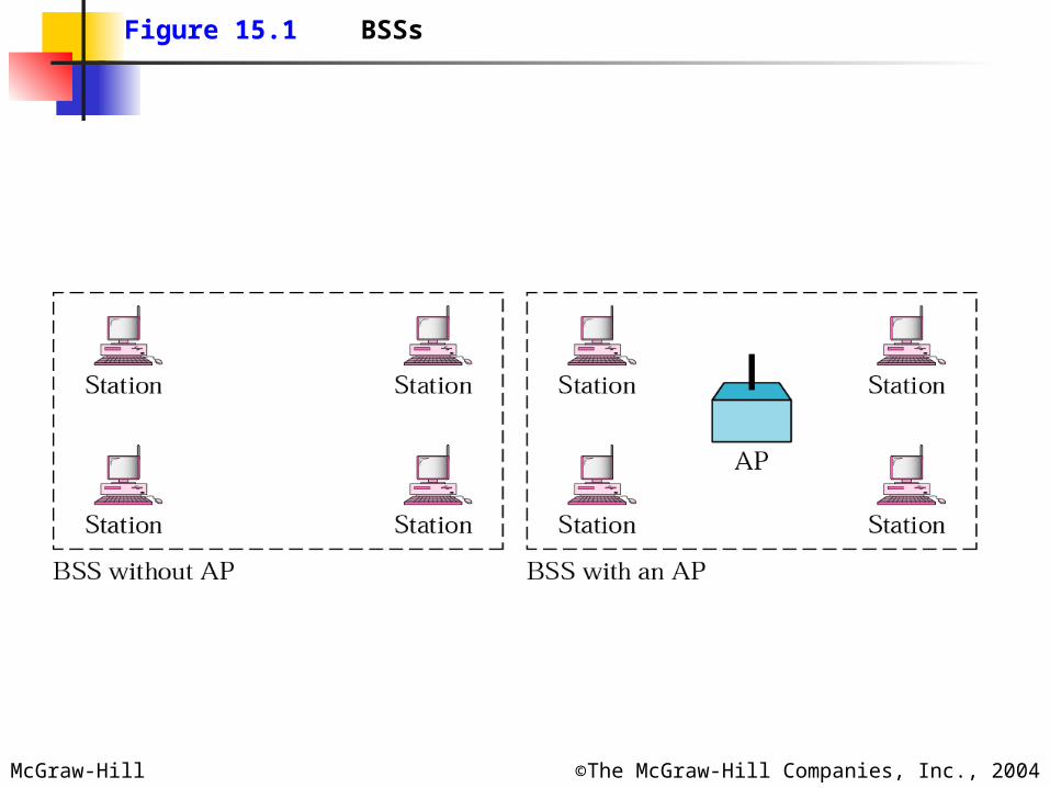
Figure 15.1 BSSs
McGraw-Hill ©The McGraw-Hill Companies, Inc., 2004
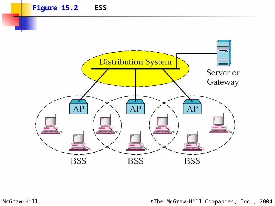
Figure 15.2 ESS
McGraw-Hill ©The McGraw-Hill Companies, Inc., 2004
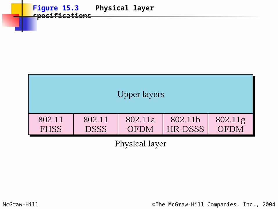
Figure 15.3 Physical layer specifications
McGraw-Hill ©The McGraw-Hill Companies, Inc., 2004
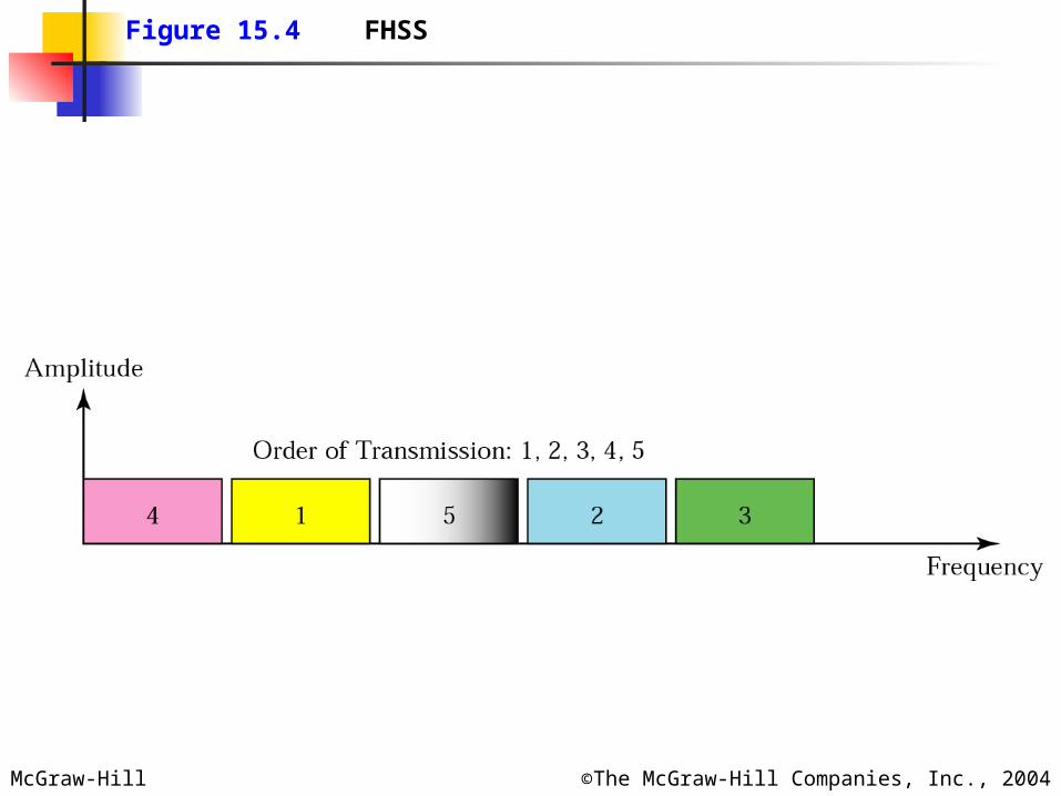
Figure 15.4 FHSS

McGraw-Hill ©The McGraw-Hill Companies, Inc., 2004
Frequency Hopping Spread Spectrum Dwell Time: 400 mseg Banda de 2.4 Ghz (ISM)
79 sub-bandas de 1 MHz FSK: 1 ó 2 bits por baud
McGraw-Hill ©The McGraw-Hill Companies, Inc., 2004
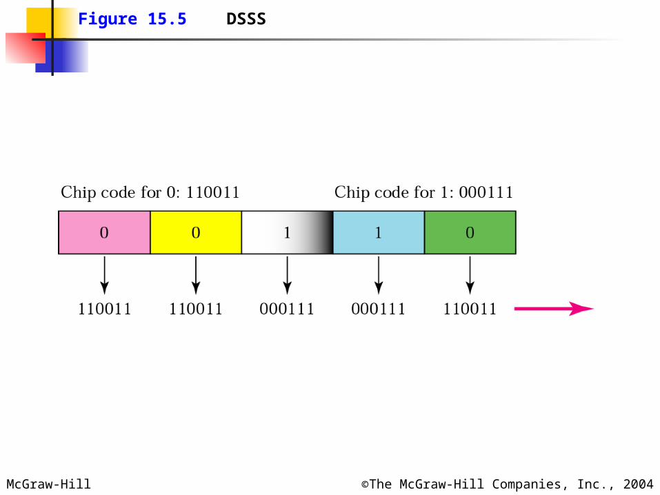
Figure 15.5 DSSS

McGraw-Hill ©The McGraw-Hill Companies, Inc., 2004
Canales DSSS
McGraw-Hill ©The McGraw-Hill Companies, Inc., 2004
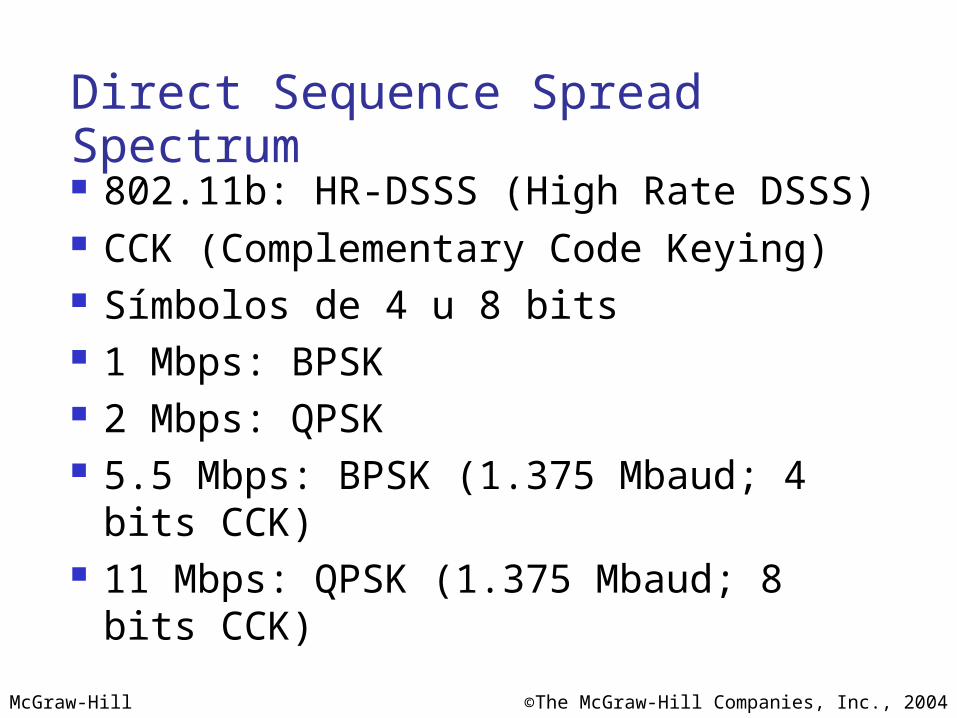
Direct Sequence Spread Spectrum 802.11b: HR-DSSS (High Rate DSSS) CCK (Complementary Code Keying) Símbolos de 4 u 8 bits 1 Mbps: BPSK 2 Mbps: QPSK 5.5 Mbps: BPSK (1.375 Mbaud; 4
bits CCK) 11 Mbps: QPSK (1.375 Mbaud; 8 bits
CCK)
McGraw-Hill ©The McGraw-Hill Companies, Inc., 2004
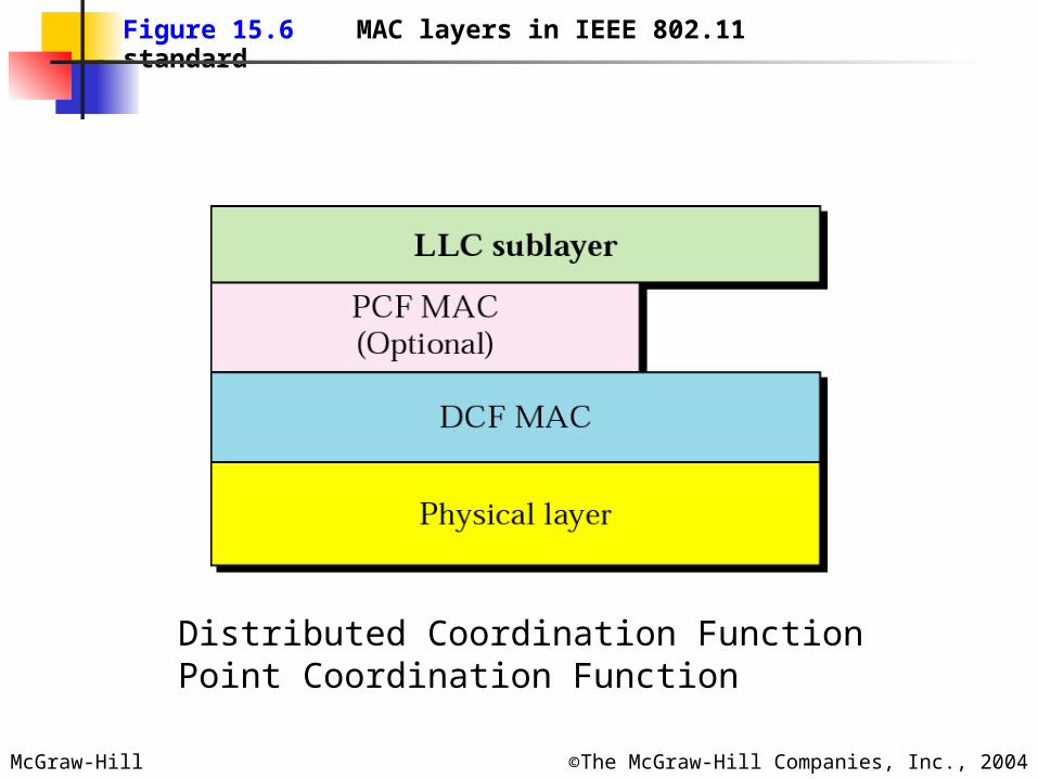
Figure 15.6 MAC layers in IEEE 802.11 standard
Distributed Coordination FunctionPoint Coordination Function
McGraw-Hill ©The McGraw-Hill Companies, Inc., 2004
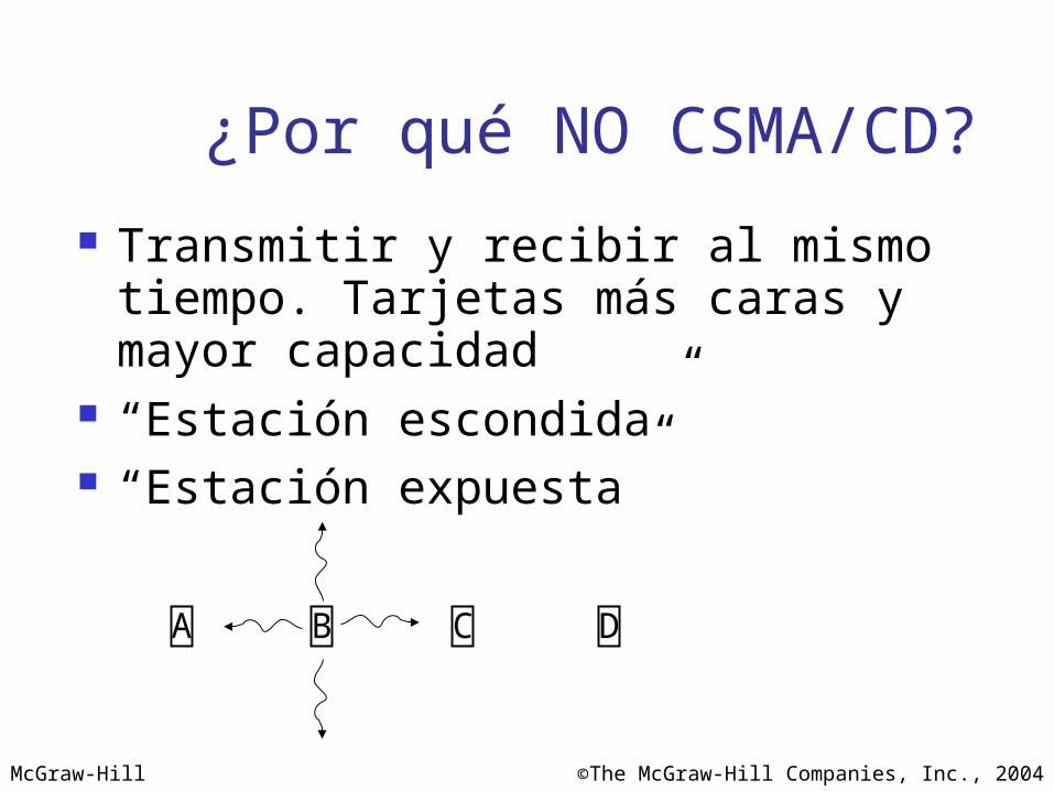
¿Por qué NO CSMA/CD?
Transmitir y recibir al mismo tiempo. Tarjetas más caras y mayor capacidad
“Estación escondida” “Estación expuesta”
A B C D

McGraw-Hill ©The McGraw-Hill Companies, Inc., 2004
Figure 15.7 CSMA/CA flowchart

McGraw-Hill ©The McGraw-Hill Companies, Inc., 2004
Figure 15.8 CSMA/CA and NAV
McGraw-Hill ©The McGraw-Hill Companies, Inc., 2004
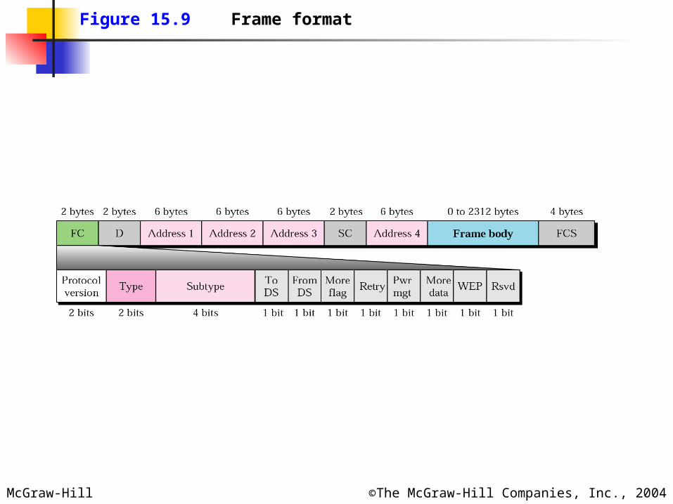
Figure 15.9 Frame format
McGraw-Hill ©The McGraw-Hill Companies, Inc., 2004
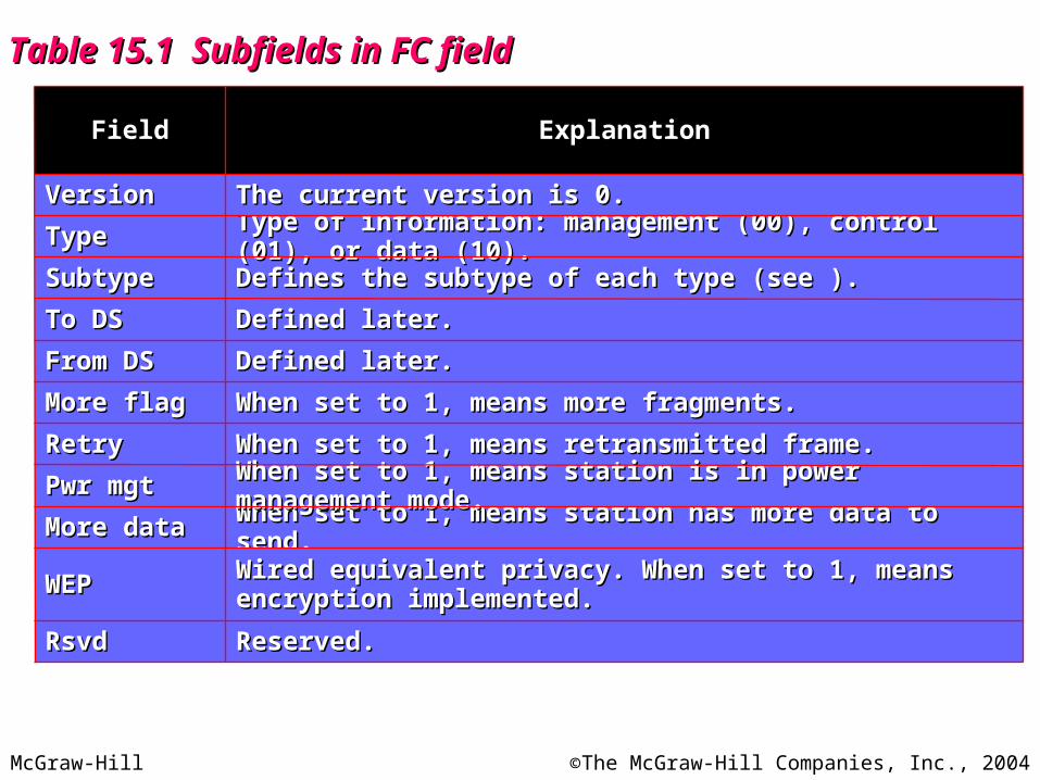
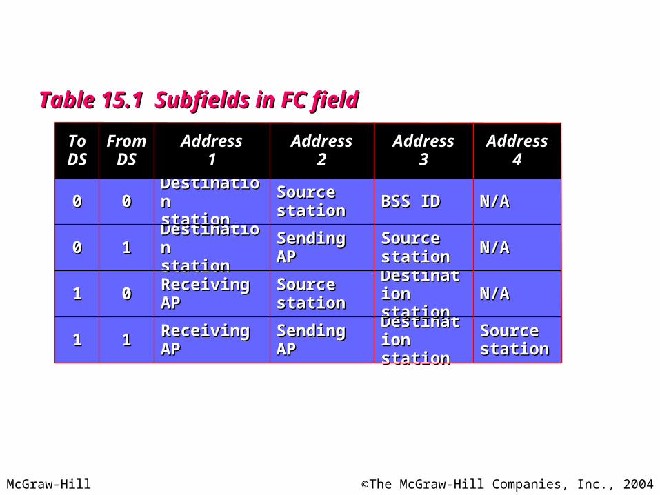
Table 15.1 Subfields in FC fieldTable 15.1 Subfields in FC field
When set to 1, means station has more data to send.When set to 1, means station has more data to send.More dataMore data
Wired equivalent privacy. When set to 1, means encryption Wired equivalent privacy. When set to 1, means encryption implemented. implemented. WEPWEP
Reserved.Reserved.RsvdRsvd
Defined later.Defined later.From DSFrom DS
When set to 1, means more fragments.When set to 1, means more fragments.More flagMore flag
When set to 1, means retransmitted frame.When set to 1, means retransmitted frame.RetryRetry
When set to 1, means station is in power management mode.When set to 1, means station is in power management mode.Pwr mgtPwr mgt
Defined later.Defined later.To DSTo DS
Defines the subtype of each type (see ).Defines the subtype of each type (see ).SubtypeSubtype
Type of information: management (00), control (01), or data (10).Type of information: management (00), control (01), or data (10).TypeType
The current version is 0.The current version is 0.
Explanation
VersionVersion
Field
McGraw-Hill ©The McGraw-Hill Companies, Inc., 2004
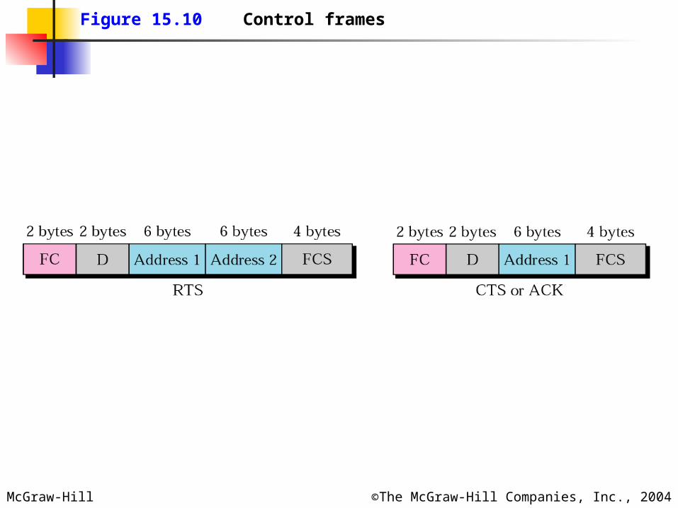
Figure 15.10 Control frames
McGraw-Hill ©The McGraw-Hill Companies, Inc., 2004
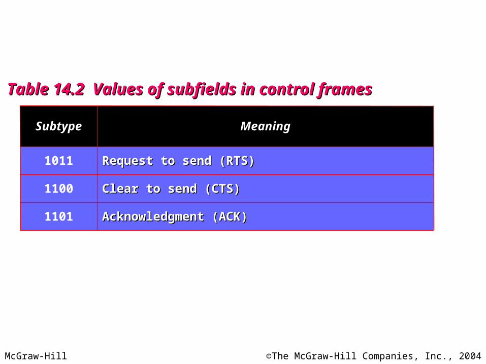
Table 14.2 Values of subfields in control framesTable 14.2 Values of subfields in control frames
Acknowledgment (ACK)Acknowledgment (ACK)1101
Clear to send (CTS)Clear to send (CTS)1100
Request to send (RTS)Request to send (RTS)
Meaning
1011
Subtype
McGraw-Hill ©The McGraw-Hill Companies, Inc., 2004
Table 15.1 Subfields in FC fieldTable 15.1 Subfields in FC field
SendingSendingAPAP
SourceSourcestationstation
SendingSendingAPAP
SourceSourcestationstation
AddressAddress22
DestinationDestinationstationstation
DestinationDestinationstationstation
SourceSourcestationstation
BSS IDBSS ID
AddressAddress33
SourceSourcestationstation
N/AN/A
N/AN/A
N/AN/A
AddressAddress44
ReceivingReceivingAPAP
ReceivingReceivingAPAP
DestinationDestinationstationstation
DestinationDestinationstationstation
AddressAddress11
11
00
11
00
FromFromDSDS
11
11
00
00
ToToDSDS
McGraw-Hill ©The McGraw-Hill Companies, Inc., 2004
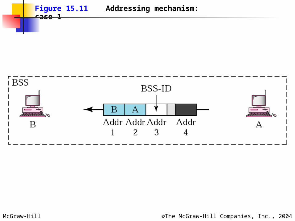
Figure 15.11 Addressing mechanism: case 1

McGraw-Hill ©The McGraw-Hill Companies, Inc., 2004
Figure 15.12 Addressing mechanism: case 2
McGraw-Hill ©The McGraw-Hill Companies, Inc., 2004
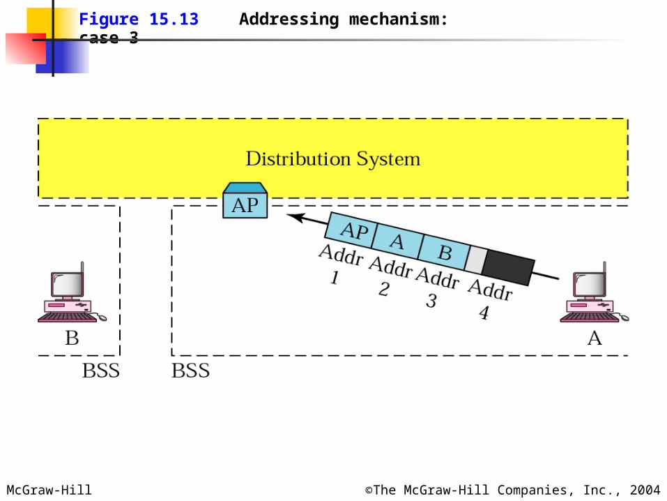
Figure 15.13 Addressing mechanism: case 3
McGraw-Hill ©The McGraw-Hill Companies, Inc., 2004
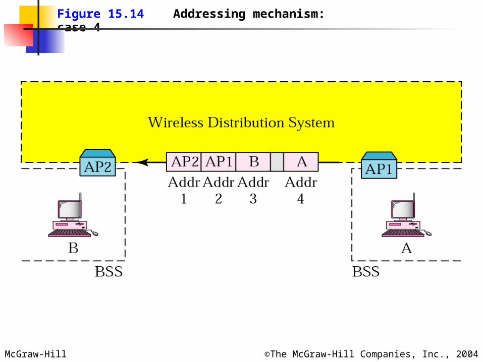
Figure 15.14 Addressing mechanism: case 4
McGraw-Hill ©The McGraw-Hill Companies, Inc., 2004
15.2 Bluetooth15.2 Bluetooth
Architecture
Radio Layer
Baseband Layer
Other Upper Layers
L2CAP Layer

McGraw-Hill ©The McGraw-Hill Companies, Inc., 2004
Figure 15.15 Piconet
McGraw-Hill ©The McGraw-Hill Companies, Inc., 2004
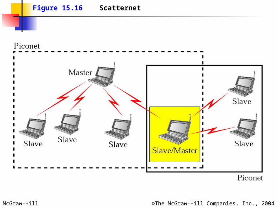
Figure 15.16 Scatternet
McGraw-Hill ©The McGraw-Hill Companies, Inc., 2004
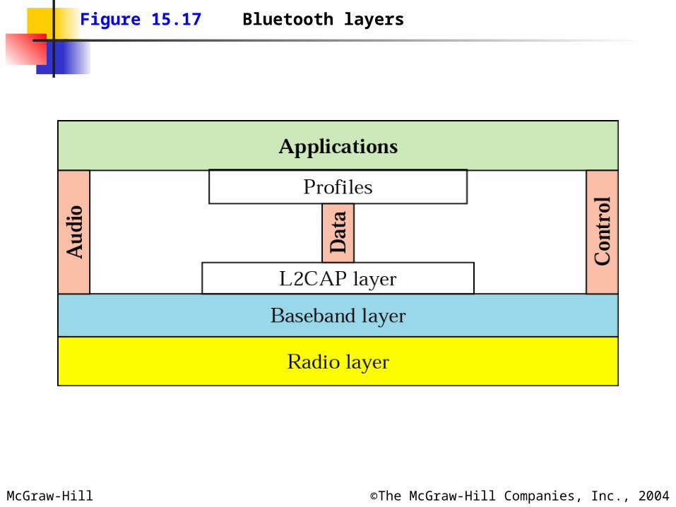
Figure 15.17 Bluetooth layers
McGraw-Hill ©The McGraw-Hill Companies, Inc., 2004
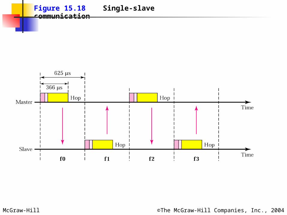
Figure 15.18 Single-slave communication
McGraw-Hill ©The McGraw-Hill Companies, Inc., 2004
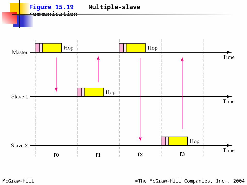
Figure 15.19 Multiple-slave communication

McGraw-Hill ©The McGraw-Hill Companies, Inc., 2004
Figure 15.20 Frame format types
McGraw-Hill ©The McGraw-Hill Companies, Inc., 2004
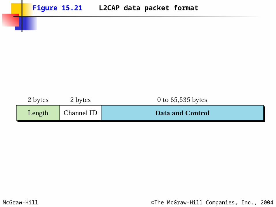
Figure 15.21 L2CAP data packet format