Embed Size (px)
Citation preview

© 2012 Microchip Technology Inc. DS52057A
MCP2210Evaluation Kit
User’s Guide

Note the following details of the code protection feature on Microchip devices:• Microchip products meet the specification contained in their particular Microchip Data Sheet.
• Microchip believes that its family of products is one of the most secure families of its kind on the market today, when used in the intended manner and under normal conditions.
• There are dishonest and possibly illegal methods used to breach the code protection feature. All of these methods, to our knowledge, require using the Microchip products in a manner outside the operating specifications contained in Microchip’s Data Sheets. Most likely, the person doing so is engaged in theft of intellectual property.
• Microchip is willing to work with the customer who is concerned about the integrity of their code.
• Neither Microchip nor any other semiconductor manufacturer can guarantee the security of their code. Code protection does not mean that we are guaranteeing the product as “unbreakable.”
Code protection is constantly evolving. We at Microchip are committed to continuously improving the code protection features of ourproducts. Attempts to break Microchip’s code protection feature may be a violation of the Digital Millennium Copyright Act. If such actsallow unauthorized access to your software or other copyrighted work, you may have a right to sue for relief under that Act.
Information contained in this publication regarding deviceapplications and the like is provided only for your convenienceand may be superseded by updates. It is your responsibility toensure that your application meets with your specifications.MICROCHIP MAKES NO REPRESENTATIONS ORWARRANTIES OF ANY KIND WHETHER EXPRESS ORIMPLIED, WRITTEN OR ORAL, STATUTORY OROTHERWISE, RELATED TO THE INFORMATION,INCLUDING BUT NOT LIMITED TO ITS CONDITION,QUALITY, PERFORMANCE, MERCHANTABILITY ORFITNESS FOR PURPOSE. Microchip disclaims all liabilityarising from this information and its use. Use of Microchipdevices in life support and/or safety applications is entirely atthe buyer’s risk, and the buyer agrees to defend, indemnify andhold harmless Microchip from any and all damages, claims,suits, or expenses resulting from such use. No licenses areconveyed, implicitly or otherwise, under any Microchipintellectual property rights.
DS52057A-page 2
QUALITY MANAGEMENT SYSTEM CERTIFIED BY DNV
== ISO/TS 16949 ==
Trademarks
The Microchip name and logo, the Microchip logo, dsPIC, KEELOQ, KEELOQ logo, MPLAB, PIC, PICmicro, PICSTART, PIC32 logo, rfPIC and UNI/O are registered trademarks of Microchip Technology Incorporated in the U.S.A. and other countries.
FilterLab, Hampshire, HI-TECH C, Linear Active Thermistor, MXDEV, MXLAB, SEEVAL and The Embedded Control Solutions Company are registered trademarks of Microchip Technology Incorporated in the U.S.A.
Analog-for-the-Digital Age, Application Maestro, chipKIT, chipKIT logo, CodeGuard, dsPICDEM, dsPICDEM.net, dsPICworks, dsSPEAK, ECAN, ECONOMONITOR, FanSense, HI-TIDE, In-Circuit Serial Programming, ICSP, Mindi, MiWi, MPASM, MPLAB Certified logo, MPLIB, MPLINK, mTouch, Omniscient Code Generation, PICC, PICC-18, PICDEM, PICDEM.net, PICkit, PICtail, REAL ICE, rfLAB, Select Mode, Total Endurance, TSHARC, UniWinDriver, WiperLock and ZENA are trademarks of Microchip Technology Incorporated in the U.S.A. and other countries.
SQTP is a service mark of Microchip Technology Incorporated in the U.S.A.
All other trademarks mentioned herein are property of their respective companies.
© 2012, Microchip Technology Incorporated, Printed in the U.S.A., All Rights Reserved.
Printed on recycled paper.
ISBN: 978-1-62076-118-2
© 2012 Microchip Technology Inc.
Microchip received ISO/TS-16949:2009 certification for its worldwide headquarters, design and wafer fabrication facilities in Chandler and Tempe, Arizona; Gresham, Oregon and design centers in California and India. The Company’s quality system processes and procedures are for its PIC® MCUs and dsPIC® DSCs, KEELOQ® code hopping devices, Serial EEPROMs, microperipherals, nonvolatile memory and analog products. In addition, Microchip’s quality system for the design and manufacture of development systems is ISO 9001:2000 certified.

MCP2210 EVALUATION KITUSER’S GUIDE
Table of Contents
Preface ........................................................................................................................... 5Introduction............................................................................................................ 5Document Layout .................................................................................................. 5Conventions Used in this Guide ............................................................................ 6Recommended Reading........................................................................................ 7The Microchip Web Site ........................................................................................ 7Customer Support ................................................................................................. 7Document Revision History ................................................................................... 7
Chapter 1. Product Overview1.1 Introduction ..................................................................................................... 91.2 MCP2210 Evaluation Kit General Description ................................................ 91.3 What The MCP2210 Evaluation Kit Includes ................................................. 9
Chapter 2. Installation and Operation2.1 Introduction ................................................................................................... 112.2 Kit Setup ....................................................................................................... 112.3 Board Operation ........................................................................................... 122.4 MCP2210 Typical Usage Scenarios ............................................................. 17
Appendix A. Schematic and LayoutsA.1 Introduction .................................................................................................. 19A.2 MCP2210 Breakout Board Schematic and Layouts ..................................... 20A.3 MCP2210 SPI Slave Motherboard Schematic and Layouts ........................ 27
Appendix B. Bill of MaterialsWorldwide Sales and Service .................................................................................... 36
© 2012 Microchip Technology Inc. DS52057A-page 3

MCP2210 Evaluation Kit User’s Guide
NOTES:
DS52057A-page 4 © 2012 Microchip Technology Inc.

MCP2210 EVALUATION KITUSER’S GUIDE
Preface
INTRODUCTIONThis chapter contains general information that will be useful to know before using the MCP2210 Evaluation Kit. Items discussed in this chapter include:• Document Layout• Conventions Used in this Guide• Recommended Reading• The Microchip Web Site• Customer Support• Document Revision History
DOCUMENT LAYOUTThis document describes how to use the MCP2210 Evaluation Kit as a development tool. The manual layout is as follows:• Chapter 1. “Product Overview” – Important information about the MCP2210
Evaluation Kit• Chapter 2. “Installation and Operation” – Covers the initial set-up of this board
and Graphical User Interface (GUI)• Appendix A. “Schematic and Layouts” – Shows the schematic and board
layouts for the MCP2210 Evaluation Kit User’s Guide• Appendix B. “Bill of Materials” – Lists the parts used to populate the MCP2210
Evaluation Kit
NOTICE TO CUSTOMERS
All documentation becomes dated, and this manual is no exception. Microchip tools and documentation are constantly evolving to meet customer needs, so some actual dialogs and/or tool descriptions may differ from those in this document. Please refer to our web site (www.microchip.com) to obtain the latest documentation available.
Documents are identified with a “DS” number. This number is located on the bottom of each page, in front of the page number. The numbering convention for the DS number is “DSXXXXXA”, where “XXXXX” is the document number and “A” is the revision level of the document.
For the most up-to-date information on development tools, see the MPLAB® IDE online help. Select the Help menu, and then Topics to open a list of available online help files.
© 2012 Microchip Technology Inc. DS52057A-page 5

MCP2210 Evaluation Kit User’s Guide
CONVENTIONS USED IN THIS GUIDEThis manual uses the following documentation conventions:
DOCUMENTATION CONVENTIONSDescription Represents Examples
Arial font:Italic characters Referenced books MPLAB® IDE User’s Guide
Emphasized text ...is the only compiler...Initial caps A window the Output window
A dialog the Settings dialogA menu selection select Enable Programmer
Quotes A field name in a window or dialog
“Save project before build”
Underlined, italic text with right angle bracket
A menu path File>Save
Bold characters A dialog button Click OKA tab Click the Power tab
N‘Rnnnn A number in verilog format, where N is the total number of digits, R is the radix and n is a digit.
4‘b0010, 2‘hF1
Text in angle brackets < > A key on the keyboard Press <Enter>, <F1>Courier New font:Plain Courier New Sample source code #define START
Filenames autoexec.bat
File paths c:\mcc18\hKeywords _asm, _endasm, staticCommand-line options -Opa+, -Opa-
Bit values 0, 1Constants 0xFF, ‘A’
Italic Courier New A variable argument file.o, where file can be any valid filename
Square brackets [ ] Optional arguments mcc18 [options] file [options]
Curly brackets and pipe character: { | }
Choice of mutually exclusive arguments; an OR selection
errorlevel {0|1}
Ellipses... Replaces repeated text var_name [, var_name...]
Represents code supplied by user
void main (void){ ...}
DS52057A-page 6 © 2012 Microchip Technology Inc.

Preface
RECOMMENDED READINGThis user's guide describes how to use MCP2210 Evaluation Kit. Other useful documents are listed below. The following Microchip documents are available and recommended as supplemental reference resources.• MCP2210 Data Sheet - “USB-to-SPI Protocol Converter with GPIO (Master
Mode)” (DS22288)
THE MICROCHIP WEB SITEMicrochip provides online support via our web site at www.microchip.com. This web site is used as a means to make files and information easily available to customers. Accessible by using your favorite Internet browser, the web site contains the following information:• Product Support – Data sheets and errata, application notes and sample
programs, design resources, user’s guides and hardware support documents, latest software releases and archived software
• General Technical Support – Frequently Asked Questions (FAQs), technical support requests, online discussion groups, Microchip consultant program member listing
• Business of Microchip – Product selector and ordering guides, latest Microchip press releases, listing of seminars and events, listings of Microchip sales offices, distributors and factory representatives
CUSTOMER SUPPORTUsers of Microchip products can receive assistance through several channels:• Distributor or Representative• Local Sales Office• Field Application Engineer (FAE)• Technical SupportCustomers should contact their distributor, representative or field application engineer (FAE) for support. Local sales offices are also available to help customers. A listing of sales offices and locations is included in the back of this document.Technical support is available through the web site at: .http://www.microchip.com/support.
DOCUMENT REVISION HISTORY
Revision A (March 2012)• Initial Release of this Document.
© 2012 Microchip Technology Inc. DS52057A-page 7

MCP2210 Evaluation Kit User’s Guide
NOTES:
DS52057A-page 8 © 2012 Microchip Technology Inc.

MCP2210 EVALUATION KITUSER’S GUIDE
Chapter 1. Product Overview
1.1 INTRODUCTIONThis chapter provides an overview of the MCP2210 Evaluation Kit and covers the following topics:• MCP2210 Evaluation Kit General Description• What The MCP2210 Evaluation Kit Includes
1.2 MCP2210 EVALUATION KIT GENERAL DESCRIPTIONThe MCP2210 Evaluation Kit (ADM00421) is a development and evaluation platform for the MCP2210 device. The kit is comprised of two connected boards:• MCP2210 Breakout Board (ADM00419)• MCP2210 SPI Slave Motherboard (ADM00420)The MCP2210 SPI Slave Motherboard is designed to work together with the MCP2210 Breakout Board (ADM00419). The motherboard provides the test-points required for measurements. It also contains the following SPI slave devices:• MCP23S08 – 8-bit I/O expander• MCP3204 – 4 channel, 12-bit ADC• 25LC02 – 2 kbit EEPROM• TC77 – Temperature sensorAll devices are SPI slaves, controlled by the MCP2210.Windows®-based PC software is used to evaluate/demonstrate the MCP2210 as a USB-to-SPI (Master) device. It allows I/O control and custom device configuration. The software is downloadable from the board web page on www.microchip.com.A DLL package is also available for development of custom PC applications using the MCP2210. The DLL package is downloadable from the board’s web page.
1.3 WHAT THE MCP2210 EVALUATION KIT INCLUDESThe MCP2210 Evaluation Kit includes (ADM00421):• MCP2210 Breakout Board (ADM00419)• MCP2210 SPI Slave Motherboard (ADM00420)• Mini-USB cable• Important Information Sheet
© 2012 Microchip Technology Inc. DS52057A-page 9
MCP2210 Evaluation Kit User’s Guide
NOTES:
DS52057A-page 10 © 2012 Microchip Technology Inc.

MCP2210 EVALUATION KITUSER’S GUIDE
Chapter 2. Installation and Operation
2.1 INTRODUCTIONThe MCP2210 Evaluation Kit is designed to demonstrate the device as a USB-to-SPI (Master) bridge solution.The Evaluation Kit is comprised of two boards that have the following features:• MCP2210 Breakout Board:
- Small plug-in board with DIP form factor (0.6 inches overall row spacing between pins)
- Mini-USB connector- Access to the SPI bus and all GP signals- PICkit™ Serial Analyzer compatible header- 3.3 or 5V jumper selectable VDD; the Breakout Board can be used to supply
up to 500 mA to the rest of the system • MCP2210 SPI Slave Motherboard:
- Socket for plugging in the MCP2210 Breakout Board- Test-points for the SPI bus and GP signals- PICkit™ Serial Analyzer header (it can be used to access only one of the SPI
slave chips present on this board – MCP23S08)- 8-bit I/O expander (MCP23S08) with eight LEDs- Four channel, 12-bit ADC (MCP3204) – a potentiometer is used to vary the
voltage on the Channel 1 ADC input- 2 kbit EEPROM – 25LC02- Temperature sensor – TC77
2.2 KIT SETUPFollow these steps to set up the MCP2210 Evaluation Kit:1. Download the support material (PC applications and DLL libraries) that can be
found on the board’s page (www.microchip.com/mcp2210evaluationkit).2. Plug the MCP2210 Breakout Board into the MCP2210 SPI Slave Motherboard.3. Connect the MCP2210 Breakout Board to a PC via a USB port. 4. The system will automatically install the driver for this board. When the
installation is complete, the board is ready for operation.5. Install the downloaded PC software.6. Start the demo application and exercise the SPI slave chip’s features.
© 2012 Microchip Technology Inc. DS52057A-page 11

MCP2210 Evaluation Kit User’s Guide
2.3 BOARD OPERATIONThe MCP2210 device is detected by a Windows®-based PC host as a Human Interface Device (HID). The accompanying software can be used to exercise the Evaluation Kit’s features. It also provides a reference point for users that want to create custom applications based on the MCP2210.
2.3.1 MCP2210 Breakout Board OperationThe MCP2210 Breakout Board can be used with either the provided motherboard, or as a stand-alone USB-to-SPI (Master) bridge module. The breakout board provides all the required signals in order to assist the user in building customized boards using the MCP2210.The breakout board has the following features:• SPI bus signals (MOSI, MISO, SCK)• 9 GP signals configurable for:
- GPIO functionality (digital input or output pins)- Chip Select functionality (working with the SPI bus signals)- Dedicated function pins
• Jumper selectable power supply: 3.3 or 5V (up to 500 mA). The board has a default connection trace between VDD and 3.3V rail, making the voltage header mounting unnecessary when powering the board with 3.3V. For 5V operation, a 3-pin header must be mounted on the board.
• PICkit™ Serial Analyzer header using GP4 as the Chip Select signal
• Dip form-factor (0.6 inches overall row spacing between pins)By using the provided software and libraries, the user can create personalized PC applications using the breakout board as a USB-to-SPI (Master) bridge adapter.
2.3.2 MCP2210 Breakout Board OperationThe MCP2210 Utility software was created for custom device setting requirements. A few of the settings that this utility can alter include VID, PID, power requirements, and string descriptors. A download link for this software can be found on the board web page. For instructions on the use of this software, refer to the software’s supporting documentation included within the application install package.
2.3.3 SPI Terminal UtilityThe SPI Terminal Utility is a tool that allows low-level data exchange at the SPI bus level. This application is useful for low-level communication and troubleshooting between the MCP2210 and various SPI slave modules.The utility window has different sections for GP designation, SPI transfer parameters and user data area.
Note: This function is available only on SPI operations, it does not work on I2C or UART signals.
DS52057A-page 12 © 2012 Microchip Technology Inc.

Installation and Operation
FIGURE 2-1: SPI TERMINAL UTILITY WINDOW
After the application is started, the state of the connection with the MCP2210 is shown in the Status Messages bar (in the lower left corner of the screen).The user can establish the GP configuration. The GPs can be used as chip select pins. Each GP Active and Idle value can be established by selecting the appropriate check-boxes, or by directly supplying the correct value in the GP Direct Settings section. The same behavior applies to the GP designation (the GP designation can be established by clicking the appropriate radio-button, or by directly supplying the GP designation value in the GP settings Direct Values section).The SPI settings pertaining to the needed SPI transfer can be established in the SPI Parameters section.The data to be sent out is filled in the Tx Data field. To send the data to the SPI slave device, press the SPI Transfer Data button on the lower right area of the screen. The data received from the SPI slave device is displayed in the Rx Data field.The user data can be supplied in either HEX or Decimal mode. This can be accomplished by selecting the HEX mode checkbox. The data in the Tx and Rx Data fields will be displayed in HEX or Decimal.
GP Settings Section
Transfer Data buttonStatus messages
SPI Transfer Parameters Section
HEX/Decimaluser data mode
SPI user data section
GP DirectSettings section
© 2012 Microchip Technology Inc. DS52057A-page 13

MCP2210 Evaluation Kit User’s Guide
A simple test using the SPI Terminal utility shows how the MCP23S08 (an 8-bit I/O expander) uses the GP4 pin of the MCP2210 device as a chip select line. This line should be active low. The GP4 must be set as in the Figure 2-1, with the IDLE option checked (IDLE value is logic ‘1’) and the ACTIVE option unchecked (ACTIVE value is logic ‘0’).The SPI parameters are set as follows:• Bit rate - 500000 bps• SPI Mode – 0• Number of bytes to transfer – 3• All the SPI related delays are set to 0The TX Data should contain the following HEX values: 40, 00, 00. Click on the SPI Transfer Data button to complete the procedure and set the MCP23S08’s port as an output. After setting this port, a value can be sent out to the port to light the LEDs on the board. To make this happen, insert the following three HEX values: 40, 0A, FF. By clicking the SPI Transfer Data button again, the inserted values are sent out to the MCP23S08 device. This command will light all the LEDs on the board. If any other LED light pattern is desired, the third value (FF) can be changed to any other 8-bit value.To verify the value written to the MCP23S08’s port, another set of data must be written into the TX Data area: 41, 0A and any other 8-bit value (a “Don’t care” value for the third position is admissible, because the read value from the MCP23S08 is received on the third byte).In the RX Data field, the third value should be the identical to the one sent out previ-ously (in the given example, FF).
2.3.4 MCP2210 Evaluation Kit demo applicationThe provided demo application is designed to work with the MCP2210 SPI Slave Motherboard using the MCP2210 Breakout Board as a USB-to-SPI bridge.The application’s source code is provided to facilitate the development of custom PC applications using the MCP2210 and the accompanying DLL package. This application was written in Visual Basic.
DS52057A-page 14 © 2012 Microchip Technology Inc.

Installation and Operation
FIGURE 2-2: VISUAL BASIC APPLICATION WINDOW
The PC GUI shows typical sections for each of the SPI slave devices present on the MCP2210 SPI Slave Motherboard.
2.3.5 MCP23S08 GPIO Expander controlsThe GUI provides specific controls in order to assist the user in exploring the I/O expander features. The control for this chip shows eight color-coded buttons, each representing an I/O option.
FIGURE 2-3: MCP23S08 GPIO EXPANDER SECTION
By double-clicking on any of the buttons, the assigned I/O pin will toggle from being a digital input to digital output and back.For the I/Os designated as digital inputs, any change on the pins will be shown on the GUI in yellow (for a logic high value) or in blue (for a logic low value).For the I/Os designated as digital outputs, a single click on any of the I/O circles will toggle their output value from logic low (in red) to logic high (in green). When a digital output is set to logic high, the corresponding LED will be lit.
2.3.6 EEPROM 25LC02 ControlsThe EEPROM GUI section presents a data-grid control and three buttons (see Figure 2-4). The data-grid is organized in eight columns and sixty-four rows. The EEPROM addresses are read from left to right, top to bottom, starting at location 0 (in
I/O Expander Section
Temperature Sensor Section
ADC Section
I/O Expander Section
Selected EEPROM Address
I/O buttons Color coded reference tablefor I/O option
© 2012 Microchip Technology Inc. DS52057A-page 15

MCP2210 Evaluation Kit User’s Guide
the first line, first column on the left). When, a particular cell in the data grid control is highlighted, the corresponding EEPROM address is displayed in the bottom left corner of the application window.
FIGURE 2-4: EEPROM 25LC02 SECTION
The EEPROM section also shows three buttons:• Read EEPROM – Press this button to read the entire EEPROM memory. The
content will show in the data-grid control.• Write EEPROM – The user can modify the data and add other hex-represented
byte values in the cells. When all the modifications are done, press this button to write the modified data-grid content on the EEPROM.
• Clear Mem – To verify the EEPROM content, press this button. This action clears only the data-grid control, not the EEPROM contents. Later, when the Read EEPROM button is pressed again, the actual EEPROM content will display in the data-grid control.
2.3.7 TC77 Temp Sensor SectionThe temperature sensor displays the temperature of the sensor device present on the motherboard in either Fahrenheit or Celsius scales.
FIGURE 2-5: TC77 TEMPERATURE SENSOR SECTION
Data-grid controls
Control buttons
Temperature unit selection TC77
temperature
DS52057A-page 16 © 2012 Microchip Technology Inc.

Installation and Operation
2.3.8 MCP3204 ADC Display SectionThe MCP3201 12-bit ADC section displays the board’s measured VDD voltage and a voltage between 0 and VDD/2, corresponding to the voltage value set by the motherboard potentiometer.
FIGURE 2-6: MCP3204 ADC VALUES DISPLAY
The remaining channels (channels 2 and 3) can also display custom user measurements of voltages between 0V – 2.5V (maximum).
2.4 MCP2210 TYPICAL USAGE SCENARIOSThe MCP2210 can be used in systems where an SPI bus is available. The MCP2210 device can be either the single master on the bus, or one of the masters sharing the bus, if a proper master-access arbitration scheme is in place.In cases where the MCP2210 is the only master on the SPI bus, a typical usage scenario is shown in Figure 2-7. The SPI bus links the SPI slave chips to the system, while a few GPs (configured for chip select function) can be used as chip select lines.If SPI slave interrupt monitoring is required, the GP6 needs to be configured for its dedicated function, in order to monitor the interrupts coming from the SPI slave chips.The PC application will handle all the details necessary for data transfer between the MCP2210 and the SPI slave devices.
VDD voltage value display
Custom voltage value display
Motherboard potentiometersettings display (between 0 and and VDD/2)
© 2012 Microchip Technology Inc. DS52057A-page 17

MCP2210 Evaluation Kit User’s Guide
FIGURE 2-7: MCP2210 TYPICAL USAGE DIAGRAM
When a system requires more than one SPI master sharing the same bus, an arbitration scheme needs to be developed, to prevent multiple SPI masters trying to access the bus at the same time. MCP2210 has support for such a mechanism, using GP7 and GP8 (configured for dedicated pin functionality) for this purpose.When GP8 is configured for its dedicated functionality, the pin can be used as a bus release request for MCP2210 coming from another master. GP7 (configured for its ded-icated functionality) is used as an SPI bus release acknowledge signal towards the requesting master. When an external SPI master requests that the MCP2210 release the bus, the MCP2210 completes the current SPI transfer (or it can be cancelled by the PC application by sending the proper USB command). Then it releases the bus, and signals this event on the acknowledge pin (GP7). The second master now has owner-ship of the bus and can keep it as long as the SPI bus request pin (GP8) is kept asserted.In conclusion, when the dedicated functionality of the GP7 and GP8 are used, MCP2210 can be used in a multiple SPI master system.
MCP2210
SPI bus
Chip-Select lines
MOSI, MISO, SCK
CS0-CS8
USBUSB-to-SPI
bridge
SPI slave chip #1 SPI slave chip #n
External Interrupt(GP6)
Interrupt Interrupt
...
DS52057A-page 18 © 2012 Microchip Technology Inc.

Installation and Operation
FIGURE 2-8: MCP2210 TYPICAL USAGE DIAGRAM
MCP2210
SPI bus
Chip-Select lines
MOSI, MISO, SCKUSBUSB-toSPI
bridge
SPI slave chip #1 SPI slave chip #n
External Interrupt(GP6)
Interrupt Interrupt
...
SPI Master #2
SPI Bus Release Request
SPI Bus Release Acknowledge
External Interrupt
GP8GP7
© 2012 Microchip Technology Inc. DS52057A-page 19

MCP2210 Evaluation Kit User’s Guide
NOTES:
DS52057A-page 20 © 2012 Microchip Technology Inc.

MCP2210 EVALUATION KITUSER’S GUIDE
Appendix A. Schematic and Layouts
A.1 INTRODUCTIONThis appendix contains the following schematics and layouts for the MCP2210 Evaluation Kit:• MCP2210 Breakout Board Schematic and Layouts
- Board – Schematic- Board – Top Silk and Pads- Board – Top Silk, Pads and Copper- Board – Top Pads and Copper- Board – Bottom Silk and Pads- Board – Bottom Silk, Pads and Copper- Board – Bottom Pads and Copper
• MCP2210 SPI Slave Motherboard Schematic and Layouts- Board – Schematic- Board – Top Silk- Board – Top Silk and Copper- Board – Top Copper- Board – Bottom Silk- Board – Bottom Silk and Copper
© 2012 Microchip Technology Inc. DS52057A-page 19

MCP2210 Evaluation Kit User’s Guide
A.2 MCP2210 BREAKOUT BOARD SCHEMATIC AND LAYOUTS
A.2.1 Board – Schematic
USB
_D-
USB
_D+
12M
Hz
2
31
X1
5%39
006
03
R1
GN
D D
VDD
VDD
Via_
1.2x
0.7
TP1
GN
D D
GN
D D
GN
D D
5V
USB
_D-
USB
_D+
VUSB
GP0
GP1
GP2
GP3
MO
SI
GP8
GP7
GP6
MIS
O
SCK
RST
OSC
2O
SC1
VDD
1
OSC
12
OSC
23
RST
4
GP0
5
GP1
6
GP2
7
GP3
8
MO
SI9
GP4
10SC
K11
GP5
12M
ISO
13G
P614
GP7
15G
P816
VUSB
17D
-18
D+
19VS
S20
VDD
OSC
1O
SC2
RST
GP0
GP1
GP2
GP3
MO
SIG
P4SC
KG
P5M
ISO
GP6
GP7
GP8
VUSBD
-D
+VS
S
MCP2210
U1
GP5
GP4
0.1u
F06
03C2
GN
D D
1uF
0603
C6
ID4
VBU
S1
GN
D5
D-
2
D+
3
IDVBU
S
GN
D
D-
D+
USB
-B-M
ini
SMD
J5
GP4
VDD
GN
D D
MISOSCK
MOSI
PICk
it™ S
eria
l A
naly
zer
Hea
der
HD
R M
1x7
VER
T
J1
GP0
GP1
GP2
GP3
GP4
MO
SI
HD
R M
J2
GP8
GP7
GP6
MIS
O
VDD
GN
D D
SCK
GP5
Left
Sid
e H
eade
rRi
ght
Side
Hea
der
12
34
56
HD
R M
1x6
VER
TJ3
1 x
7 V
ER
T
7654321
7654321
5V
GN
D D
0.1u
F06
03
C50.
1uF
0603
C4
GN
D D
GN
D D
GN
D D
12
3
HD
R M
J4
VDD
5V
VUSB
3.3V
GN
D D
VOU
T3
VIN
1
GND 2
VOU
TVI
N
GND
MCP1825S-3.3V
U2
4.7u
F06
03C3
NT1
22uF
1206
C1
1 x 3
VER
T
Def
ault
conn
ectio
nbe
twee
n 1
- 2. U
ser t
ocu
t the
trac
e if
5V V
DD
is
nee
ded.
DS52057A-page 20 © 2012 Microchip Technology Inc.

Schematic and Layouts
A.2.2 Board – Top Silk and Pads
© 2012 Microchip Technology Inc. DS52057A-page 21

MCP2210 Evaluation Kit User’s Guide
A.2.3 Board – Top Silk, Pads and Copper
DS52057A-page 22 © 2012 Microchip Technology Inc.

Schematic and Layouts
A.2.4 Board – Top Pads and Copper
© 2012 Microchip Technology Inc. DS52057A-page 23

MCP2210 Evaluation Kit User’s Guide
A.2.5 Board – Bottom Silk and Pads
DS52057A-page 24 © 2012 Microchip Technology Inc.
Schematic and Layouts
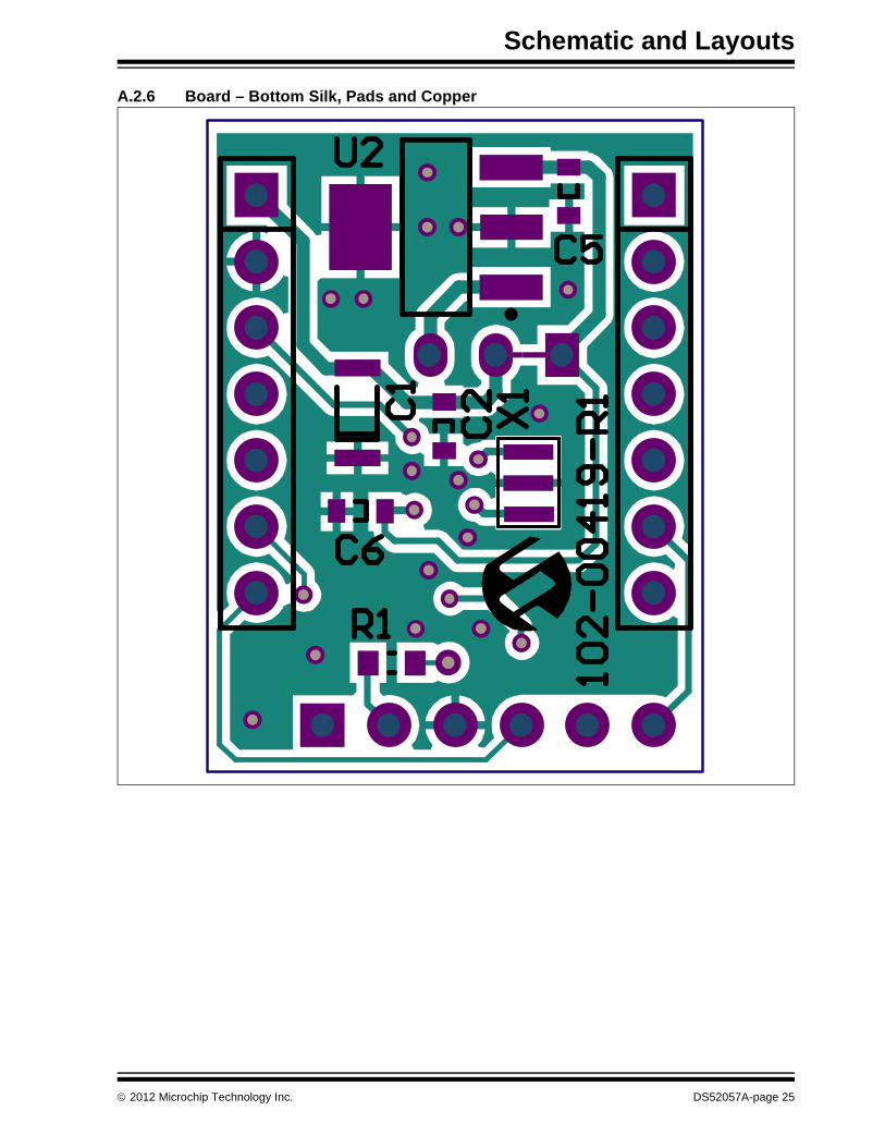
A.2.6 Board – Bottom Silk, Pads and Copper
© 2012 Microchip Technology Inc. DS52057A-page 25

MCP2210 Evaluation Kit User’s Guide
A.2.7 Board – Bottom Pads and Copper
DS52057A-page 26 © 2012 Microchip Technology Inc.

Schematic and Layouts
A.3 MCP2210 SPI SLAVE MOTHERBOARD SCHEMATIC AND LAYOUTS
A.3.1 Board – Schematic
HD
R M
1x6
RA
J10
GP4
VDD
MIS
OSC
KM
OSI
HD
R M
1x7
VER
T
J11
GP0
GP1
GP2
GP3
GP4
MO
SI
HD
R M
1x7
VER
TJ13
GP8
GP7
GP6
MIS
O
VDD
GN
D
SCK
GP5
Left
Sid
e H
eade
rRi
ght
Side
Hea
der
GP2
GP3
GP8
GP6
GP5
VDD
GN
D
1J6GP2
1J2GP3
1J9GP8
1J3GP5
1J8GP6
1J14
VDD
1J15
GN
DGN
D
VIN
1VO
UT
2
VSS
3
MCP1525
U5
GN
D
VDD
VREF
0.1u
F
0603
C6G
ND
1J1
9VR
EF
4.7u
F06
03
C5G
ND
GN
D
SCK
MO
SIM
ISO
0.1u
F06
03
C1
VDD
GP0
EEPR
OM
1J5GP0
CS1
SO2
WP
3
VSS
4SI
5SC
K6
HO
LD7
VCC
8CS SO
WP
VSS
SISCSK
HO
LD
VCC
25LC
020
U2
SCK
1
SI2
SO3
A1
4G
P515
GP6
16G
P717
VDD
18SC
KSI SO A
1G
P5G
P6G
P7VD
D
A0
5
RESE
T6
CS7
INT
8
VSS
9
GP4
14
GP3
13
GP2
12
GP1
11
GP0
10
MCP23S08
U1
VDD
GN
D
0.1u
F
0603
C2
GN
D
10k
5%0603
R7
1k 1% 0603
R21k 1% 06
03
R31k 1% 06
03
R41k 1% 06
03
R51k 1% 06
03
R61k 1% 06
03
R81k 1% 06
03
R91k 1% 06
03
R10
1 2
LD1
1 2
LD2
1 2
LD3
1 2
LD4
1 2
LD5
1 2
LD6
1 2
LD7
1 2
LD8
GN
DG
ND
GN
DG
ND
GN
DG
ND
GN
DG
ND
VDD
GN
D
SCK
MO
SIM
ISO
GP4
1 J7 GP4
I/O E
XPA
ND
ER
HD
R M
2x8
VER
T12
3456
78910
11121314
1516J1
2
GP6
1k 1% 0603
R1
SI/O
1
SCK
2
NC
3
VSS
4N
C5
NC
6CS
7VD
D8
SI/O
SCK
NC
VSS
NC
NCCS
VDD
TC77
SPI
5V
U4
VDD
GN
D
SCK
MO
SI
MIS
OG
ND
GP7
TEM
P
1 J4 GP7
1 J17
SCK
1 J16
MO
SI
1J20
MIS
O
33k
5%0603
R11
0.1u
F
0603
C4
VDD
GN
D
SCK
MIS
O
GN
D
1k1%06
03R1
5
VDD
GP
1
AD
C
132
10k
R17
0.1u
F06
03C3
10k
1%06
03
R16
1 J1 GP1
1J23
CH0
1 J22
CH1
CH0
1
CH1
2
CH2
3
CH3
4
NC
5
NC
6
DG
ND
7CS
/SH
DN
8D
in9
Dou
t10
CLK
11A
GN
D12
Vref
13Vd
d14
CH0
CH1
CH2
CH3
NC
NC
DG
ND
CS/S
HD
NDin
Dou
tCL
KA
GN
DVr
efVd
d
MCP3204
U3
1
J18
CH2
1
J21
CH3
VREF
MO
SI
GN
D
4.7u
F06
03
C7
1k1%06
03R1
4
1k 1% 0603
R12
1k 1% 0603
R13
Ferr
ite B
ead
0603
L1
AG
ND
AG
ND
AG
ND
PICk
it™ S
eria
l Ana
lyze
r Hea
der
6 5 4 3 2 1
7 6 5 4 3 2 1
7 6 5 4 3 2 1
© 2012 Microchip Technology Inc. DS52057A-page 27

MCP2210 Evaluation Kit User’s Guide
A.3.2 Board – Top Silk
DS52057A-page 28 © 2012 Microchip Technology Inc.

Schematic and Layouts
A.3.3 Board – Top Silk and Copper
© 2012 Microchip Technology Inc. DS52057A-page 29

MCP2210 Evaluation Kit User’s Guide
A.3.4 Board – Top Copper
DS52057A-page 30 © 2012 Microchip Technology Inc.

Schematic and Layouts
A.3.5 Board – Bottom Silk
© 2012 Microchip Technology Inc. DS52057A-page 31

MCP2210 Evaluation Kit User’s Guide
A.3.6 Board – Bottom Silk and Copper
DS52057A-page 32 © 2012 Microchip Technology Inc.

MCP2210 EVALUATION KITUSER’S GUIDE
Appendix B. Bill of Materials
TABLE B-1: BILL OF MATERIALS - MCP2210 BREAKOUT BOARDQty Reference Description_ Manufacturer Part Number
1 C1 Cap. Cer. 22 uF 10V 20% Y5V 1206 TDK®Corporation C3216Y5V1A226Z3 C2, C4, C5 Cap. Cer. 1 uF 10% 16V X7R 0603 AVX Corporation 0603YC104KAT2A1 C3 Cap. Cer. 4.7 uF 6.3V 10% X5R 0603 TDK Corporation C1608X5R0J475K1 C6 Cap. Cer. 1 uF 16V 10% X7R 0603 TDK Corporation C1608X7R1C105K2 J1, J2 DO NOT POPULATE
Conn. Hdr. Male .100 1x7 POS Vert. TE Connectivity Ltd. HDR M 1x7 Vertical
1 J3 DO NOT POPULATEConn. Hdr. Male .100 1x6 POS Vert.
TE Connectivity Ltd. HDR M 1x6 Vertical
1 J4 DO NOT POPULATEConn. Hdr. Male .100 1x3 POS Vert.
TE Connectivity Ltd. HDR M 1x3 Vertical
1 J5 Conn. Rcpt. USB Mini B R/A SMD Hirose Electric Co. Ltd. UX60SC-MB-5ST(80)1 PCB RoHS compliant bare PCB, MCP2210
Breakout Board — 104-00419
1 R1 Res. 390 Ohm 1/10W 5% 0603 SMD Panasonic® - ECG ERJ-3GEYJ391V1 U1 IC USB-TO-SPI SSOP-20 Microchip Technology
Inc.MCP2210-I/SS
1 U2 IC LDO Reg. 500 mA 3.3V SOT-223-3 Microchip Technology Inc.
MCP1825S-3302E/DB
1 X1 Cer. Resonator 12.0 MHz SMD Murata Electronics® CSTCE12M0G55-R0Note 1: The components listed in this Bill of Materials are representative of the PCB assembly. The released BOM
used in manufacturing uses all RoHS-compliant components.
TABLE B-2: BILL OF MATERIALS - MCP2210 SPI SLAVE MOTHERBOARDQty Reference Description_ Manufacturer Part Number
5 C1, C2, C3, C4, C6
Cap. Cer. 0.1 uF 50V X7R 10% 0603 TDK Corporation C1608X7R1H104K
2 C5, C7 Cap. Cer. 4.7 uF 6.3V 10% X5R 0603 TDK Corporation C1608X5R0J475K19 J1, J2, J3, J4,
J5, J6, J7, J8, J9, J14, J15, J16, J17, J18, J19, J20, J21, J22, J23
PC test point Tin SMD Harwin Plc. S1751-46R
1 J10 Conn. Hdr. Male .100 1x6 Pos. RA TE Connectivity Ltd. HDR M 1x6 RA2 J11, J13 Conn. Hdr. Male .100 1x7 Pos. Vert. TE Connectivity Ltd. HDR M 1x7 Vertical1 J12 Conn. Hdr. Male .100 2x8 Pos. Vert. TE Connectivity Ltd. HDR M 2x8 Vertical1 L1 Ferrite Chip 47 Ohms 500 mA 0603 Laird Technologies® LI0603E470R-10
Note 1: The components listed in this Bill of Materials are representative of the PCB assembly. The released BOM used in manufacturing uses all RoHS-compliant components.
© 2012 Microchip Technology Inc. DS52057A-page 33

MCP2210 Evaluation Kit User’s Guide
8 LD1, LD2, LD3, LD4, LD5, LD6, LD7, LD8
LED Smartled Red 630 nm 0603 OSRAM Opto Semiconductors GmbH.
LS L29K-G1J2-1-0-2-R18-Z
1 PCB RoHS compliant bare PCB, MCP2210 SPI Slave Motherboard
— 104-00420
13 R1, R2, R3, R4, R5, R6, R8, R9, R10, R12, R13, R14, R15
Res. 1k Ohm 1/10W 1% 0603 SMD Panasonic - ECG ERJ-3EKF1001V
1 R7 Res. 10k Ohm 1/10W 5% 0603 SMD Panasonic - ECG ERJ-3GEYJ103V1 R11 Res. 33k Ohm 1/10W 5% 0603 SMD Panasonic - ECG ERJ-3GEYJ333V1 R16 Res. 10k Ohm 1/10W 1% 0603 SMD Panasonic - ECG ERJ-3EKF1002V1 R17 Trimmer 10K OHM 0.5W TH Bourns®, Inc. 3386F-1-103TLF1 U1 IC I/O Expander SPI 8B SOIC-18 Microchip Technology
Inc.MCP23S08-E/SO
1 U2 IC EEPROM 2k Bit 10 MHz SOIC-8 Microchip Technology Inc.
25LC020A-I/SN
1 U3 IC ADC 12 BIT 2.7V 4 Ch. SPI SOIC-14 Microchip Technology Inc.
MCP3204T-CI/SL
1 U4 IC Sensor Thermal SPI 5V SOIC-8 Microchip Technology Inc.
TC77-5.0MOA
1 U5 IC Volt. Ref. 2.5V SOT-23-3 Microchip Technology Inc.
MCP1525T-I/TT
TABLE B-2: BILL OF MATERIALS - MCP2210 SPI SLAVE MOTHERBOARD (CONTINUED)Qty Reference Description_ Manufacturer Part Number
Note 1: The components listed in this Bill of Materials are representative of the PCB assembly. The released BOM used in manufacturing uses all RoHS-compliant components.
DS52057A-page 34 © 2012 Microchip Technology Inc.

Bill of Materials
NOTES:
© 2012 Microchip Technology Inc. DS52057A-page 35

DS52057A-page 36 © 2012 Microchip Technology Inc.
AMERICASCorporate Office2355 West Chandler Blvd.Chandler, AZ 85224-6199Tel: 480-792-7200 Fax: 480-792-7277Technical Support: http://www.microchip.com/supportWeb Address: www.microchip.comAtlantaDuluth, GA Tel: 678-957-9614 Fax: 678-957-1455BostonWestborough, MA Tel: 774-760-0087 Fax: 774-760-0088ChicagoItasca, IL Tel: 630-285-0071 Fax: 630-285-0075ClevelandIndependence, OH Tel: 216-447-0464 Fax: 216-447-0643DallasAddison, TX Tel: 972-818-7423 Fax: 972-818-2924DetroitFarmington Hills, MI Tel: 248-538-2250Fax: 248-538-2260IndianapolisNoblesville, IN Tel: 317-773-8323Fax: 317-773-5453Los AngelesMission Viejo, CA Tel: 949-462-9523 Fax: 949-462-9608Santa ClaraSanta Clara, CA Tel: 408-961-6444Fax: 408-961-6445TorontoMississauga, Ontario, CanadaTel: 905-673-0699 Fax: 905-673-6509
ASIA/PACIFICAsia Pacific OfficeSuites 3707-14, 37th FloorTower 6, The GatewayHarbour City, KowloonHong KongTel: 852-2401-1200Fax: 852-2401-3431Australia - SydneyTel: 61-2-9868-6733Fax: 61-2-9868-6755China - BeijingTel: 86-10-8569-7000 Fax: 86-10-8528-2104China - ChengduTel: 86-28-8665-5511Fax: 86-28-8665-7889China - ChongqingTel: 86-23-8980-9588Fax: 86-23-8980-9500China - HangzhouTel: 86-571-2819-3187 Fax: 86-571-2819-3189China - Hong Kong SARTel: 852-2401-1200 Fax: 852-2401-3431China - NanjingTel: 86-25-8473-2460Fax: 86-25-8473-2470China - QingdaoTel: 86-532-8502-7355Fax: 86-532-8502-7205China - ShanghaiTel: 86-21-5407-5533 Fax: 86-21-5407-5066China - ShenyangTel: 86-24-2334-2829Fax: 86-24-2334-2393China - ShenzhenTel: 86-755-8203-2660 Fax: 86-755-8203-1760China - WuhanTel: 86-27-5980-5300Fax: 86-27-5980-5118China - XianTel: 86-29-8833-7252Fax: 86-29-8833-7256China - XiamenTel: 86-592-2388138 Fax: 86-592-2388130China - ZhuhaiTel: 86-756-3210040 Fax: 86-756-3210049
ASIA/PACIFICIndia - BangaloreTel: 91-80-3090-4444 Fax: 91-80-3090-4123India - New DelhiTel: 91-11-4160-8631Fax: 91-11-4160-8632India - PuneTel: 91-20-2566-1512Fax: 91-20-2566-1513Japan - OsakaTel: 81-66-152-7160 Fax: 81-66-152-9310Japan - YokohamaTel: 81-45-471- 6166 Fax: 81-45-471-6122Korea - DaeguTel: 82-53-744-4301Fax: 82-53-744-4302Korea - SeoulTel: 82-2-554-7200Fax: 82-2-558-5932 or 82-2-558-5934Malaysia - Kuala LumpurTel: 60-3-6201-9857Fax: 60-3-6201-9859Malaysia - PenangTel: 60-4-227-8870Fax: 60-4-227-4068Philippines - ManilaTel: 63-2-634-9065Fax: 63-2-634-9069SingaporeTel: 65-6334-8870Fax: 65-6334-8850Taiwan - Hsin ChuTel: 886-3-5778-366Fax: 886-3-5770-955Taiwan - KaohsiungTel: 886-7-536-4818Fax: 886-7-330-9305Taiwan - TaipeiTel: 886-2-2500-6610 Fax: 886-2-2508-0102Thailand - BangkokTel: 66-2-694-1351Fax: 66-2-694-1350
EUROPEAustria - WelsTel: 43-7242-2244-39Fax: 43-7242-2244-393Denmark - CopenhagenTel: 45-4450-2828 Fax: 45-4485-2829France - ParisTel: 33-1-69-53-63-20 Fax: 33-1-69-30-90-79Germany - MunichTel: 49-89-627-144-0 Fax: 49-89-627-144-44Italy - Milan Tel: 39-0331-742611 Fax: 39-0331-466781Netherlands - DrunenTel: 31-416-690399 Fax: 31-416-690340Spain - MadridTel: 34-91-708-08-90Fax: 34-91-708-08-91UK - WokinghamTel: 44-118-921-5869Fax: 44-118-921-5820
Worldwide Sales and Service
11/29/11