Embed Size (px)
Citation preview
© 2006 Microchip Technology Inc. DS51267B
MCP7382XEvaluation Kit
User’s Guide
Note the following details of the code protection feature on Microchip devices:• Microchip products meet the specification contained in their particular Microchip Data Sheet.
• Microchip believes that its family of products is one of the most secure families of its kind on the market today, when used in the intended manner and under normal conditions.
• There are dishonest and possibly illegal methods used to breach the code protection feature. All of these methods, to our knowledge, require using the Microchip products in a manner outside the operating specifications contained in Microchip’s Data Sheets. Most likely, the person doing so is engaged in theft of intellectual property.
• Microchip is willing to work with the customer who is concerned about the integrity of their code.
• Neither Microchip nor any other semiconductor manufacturer can guarantee the security of their code. Code protection does not mean that we are guaranteeing the product as “unbreakable.”
Code protection is constantly evolving. We at Microchip are committed to continuously improving the code protection features of ourproducts. Attempts to break Microchip’s code protection feature may be a violation of the Digital Millennium Copyright Act. If such actsallow unauthorized access to your software or other copyrighted work, you may have a right to sue for relief under that Act.
Information contained in this publication regarding deviceapplications and the like is provided only for your convenienceand may be superseded by updates. It is your responsibility toensure that your application meets with your specifications.MICROCHIP MAKES NO REPRESENTATIONS ORWARRANTIES OF ANY KIND WHETHER EXPRESS ORIMPLIED, WRITTEN OR ORAL, STATUTORY OROTHERWISE, RELATED TO THE INFORMATION,INCLUDING BUT NOT LIMITED TO ITS CONDITION,QUALITY, PERFORMANCE, MERCHANTABILITY ORFITNESS FOR PURPOSE. Microchip disclaims all liabilityarising from this information and its use. Use of Microchipdevices in life support and/or safety applications is entirely atthe buyer’s risk, and the buyer agrees to defend, indemnify andhold harmless Microchip from any and all damages, claims,suits, or expenses resulting from such use. No licenses areconveyed, implicitly or otherwise, under any Microchipintellectual property rights.
DS51267B-page ii
Trademarks
The Microchip name and logo, the Microchip logo, Accuron, dsPIC, KEELOQ, microID, MPLAB, PIC, PICmicro, PICSTART, PRO MATE, PowerSmart, rfPIC and SmartShunt are registered trademarks of Microchip Technology Incorporated in the U.S.A. and other countries.
AmpLab, FilterLab, Migratable Memory, MXDEV, MXLAB, SEEVAL, SmartSensor and The Embedded Control Solutions Company are registered trademarks of Microchip Technology Incorporated in the U.S.A.
Analog-for-the-Digital Age, Application Maestro, CodeGuard, dsPICDEM, dsPICDEM.net, dsPICworks, ECAN, ECONOMONITOR, FanSense, FlexROM, fuzzyLAB, In-Circuit Serial Programming, ICSP, ICEPIC, Linear Active Thermistor, Mindi, MiWi, MPASM, MPLIB, MPLINK, PICkit, PICDEM, PICDEM.net, PICLAB, PICtail, PowerCal, PowerInfo, PowerMate, PowerTool, REAL ICE, rfLAB, rfPICDEM, Select Mode, Smart Serial, SmartTel, Total Endurance, UNI/O, WiperLock and ZENA are trademarks of Microchip Technology Incorporated in the U.S.A. and other countries.
SQTP is a service mark of Microchip Technology Incorporated in the U.S.A.
All other trademarks mentioned herein are property of their respective companies.
© 2006, Microchip Technology Incorporated, Printed in the U.S.A., All Rights Reserved.
Printed on recycled paper.
© 2006 Microchip Technology Inc.
Microchip received ISO/TS-16949:2002 certification for its worldwide headquarters, design and wafer fabrication facilities in Chandler and Tempe, Arizona, Gresham, Oregon and Mountain View, California. The Company’s quality system processes and procedures are for its PICmicro® 8-bit MCUs, KEELOQ® code hopping devices, Serial EEPROMs, microperipherals, nonvolatile memory and analog products. In addition, Microchip’s quality system for the design and manufacture of development systems is ISO 9001:2000 certified.
MCP7382X EVALUATION KITUSER’S GUIDE
Table of Contents
Preface ........................................................................................................................... 1Chapter 1. Product Overview ....................................................................................... 5
1.1 Introduction ..................................................................................................... 51.2 What the MCP7382X Evaluation Kit Is ........................................................... 51.3 MCP7382X Evaluation Kit Components ......................................................... 5
Chapter 2. Installation and Operation ......................................................................... 72.1 Description ..................................................................................................... 72.2 Features ......................................................................................................... 72.3 Getting Started ............................................................................................... 82.4 Detailed Description ....................................................................................... 9
Appendix A. Schematic and Board Layouts.............................................................. 11A.1 Introduction .................................................................................................. 11A.2 Highlights ..................................................................................................... 11A.3 Board Schematic ........................................................................................ 12A.4 Board Layout - Top Assembly .................................................................... 13A.5 Board Layout - Top Layer .......................................................................... 14A.6 Board Layout - Bottom Layer ..................................................................... 15
Appendix B. Bill Of Materials (BOM) .......................................................................... 17Worldwide Sales and Service .................................................................................... 18
© 2006 Microchip Technology Inc. DS51267B-page iii
MCP7382X Evaluation Kit User’s Guide
NOTES:
DS51267B-page iv © 2006 Microchip Technology Inc.
MCP7382X EVALUATION KITUSER’S GUIDE
Preface
INTRODUCTIONThis chapter contains general information that will be useful to know before using the MCP7382X Evaluation Kit. Items discussed in this chapter include:• Document Layout• Conventions Used in this Guide• Recommended Reading• The Microchip Web Site• Customer Support• Document Revision History
DOCUMENT LAYOUTThis document describes how to use the MCP7382X Evaluation Kit as a development tool. The manual layout is as follows:• Chapter 1. “Product Overview” – Important information on how to use the
MCP7382X Evaluation Board.• Chapter 2. “Installation and Operation” – For users evaluating the MCP73826,
MCP73827, or MCP73828 devices, this chapter describes how to use the various features of the hardware.
• Appendix A. “Schematic and Board Layouts” – shows the schematic and lay-out diagrams for the MCP7382X Evaluation Kit.
• Appendix B. “Bill Of Materials (BOM)” – lists the parts used to build the MCP7382X Evaluation Kit.
NOTICE TO CUSTOMERS
All documentation becomes dated, and this manual is no exception. Microchip tools and documentation are constantly evolving to meet customer needs, so some actual dialogs and/or tool descriptions may differ from those in this document. Please refer to our web site (www.microchip.com) to obtain the latest documentation available.
Documents are identified with a “DS” number. This number is located on the bottom of each page, in front of the page number. The numbering convention for the DS number is “DSXXXXXA”, where “XXXXX” is the document number and “A” is the revision level of the document.
© 2006 Microchip Technology Inc. DS51267B-page 1
MCP7382X Evaluation Kit User’s Guide
CONVENTIONS USED IN THIS GUIDEThis manual uses the following documentation conventions:
RECOMMENDED READINGThis user's guide describes how to use MCP7382X Evaluation Kit. For more information regarding the MCP7382X devices, the following are recommended reading.
MCP7382X Data SheetsThese data sheets provide detailed information regarding the MCP7382X Single Cell Lithium-Ion Charge Management Controllers:
• MCP73826 Data Sheet (DS21705)• MCP73827 Data Sheet (DS21704)• MCP73828 Data Sheet (DS21706)
DOCUMENTATION CONVENTIONSDescription Represents Examples
Arial font:Italic characters Referenced books MPLAB® IDE User’s Guide
Emphasized text ...is the only compiler...Initial caps A window the Output window
A dialog the Settings dialogA menu selection select Enable Programmer
Quotes A field name in a window or dialog
“Save project before build”
Underlined, italic text with right angle bracket
A menu path File>Save
Bold characters A dialog button Click OKA tab Click the Power tab
N‘Rnnnn A number in verilog format, where N is the total number of digits, R is the radix and n is a digit.
4‘b0010, 2‘hF1
Text in angle brackets < > A key on the keyboard Press <Enter>, <F1>Courier New font:Plain Courier New Sample source code #define START
Filenames autoexec.batFile paths c:\mcc18\h
Keywords _asm, _endasm, static
Command-line options -Opa+, -Opa-Bit values 0, 1
Constants 0xFF, ‘A’
Italic Courier New A variable argument file.o, where file can be any valid filename
Square brackets [ ] Optional arguments mcc18 [options] file [options]
Curly brackets and pipe character: { | }
Choice of mutually exclusive arguments; an OR selection
errorlevel {0|1}
DS51267B-page 2 © 2006 Microchip Technology Inc.
Preface
THE MICROCHIP WEB SITEMicrochip provides online support via our web site at www.microchip.com. This web site is used as a means to make files and information easily available to customers. Accessible by using your favorite Internet browser, the web site contains the following information:• Product Support – Data sheets and errata, application notes and sample
programs, design resources, user’s guides and hardware support documents, latest software releases and archived software
• General Technical Support – Frequently Asked Questions (FAQs), technical support requests, online discussion groups, Microchip consultant program member listing
• Business of Microchip – Product selector and ordering guides, latest Microchip press releases, listing of seminars and events, listings of Microchip sales offices, distributors and factory representatives
CUSTOMER SUPPORTUsers of Microchip products can receive assistance through several channels:• Distributor or Representative• Local Sales Office• Field Application Engineer (FAE)• Technical Support• Development Systems Information LineCustomers should contact their distributor, representative or field application engineer for support. Local sales offices are also available to help customers. A listing of sales offices and locations is included in the back of this document.Technical support is available through the web site at: http://support.microchip.com
DOCUMENT REVISION HISTORY
Revision B (July 2006)• Add disclaimer to Bill of Materials regarding RoHS-Compliant part numbers.
Revision A (January 2002)• Initial Release of this Document.
© 2006 Microchip Technology Inc. DS51267B-page 3

MCP7382X Evaluation Kit User’s Guide
NOTES:
DS51267B-page 4 © 2006 Microchip Technology Inc.
MCP7382X EVALUATION KITUSER’S GUIDE
Chapter 1. Product Overview
1.1 INTRODUCTIONThis chapter provides an overview of the MCP7382X Evaluation Kit, and instructions on how to connect the system components.This chapter covers the following topics:• What the MCP7382X Evaluation Kit Is• MCP7382X Evaluation Kit Components
1.2 WHAT THE MCP7382X EVALUATION KIT ISThe MCP7382X Evaluation Kit is an evaluation and demonstration tool for Microchip Technology’s MCP7382X Single Cell Lithium-Ion Charge Management Controllers. The design provides for dynamic versatility while being able to handle accurate measurements.When connected, this evaluation board allows for the evaluation of the MCP7382X devices in a variety of applications.
1.3 MCP7382X EVALUATION KIT COMPONENTSThe MCP7382X Evaluation Kit contains:• MCP7382X Evaluation Board (102-00017)• MCP73826-4.2VCH, MCP73827-4.2VUA, and MCP73828-4.2VUA Devices
installed• Analog and Interface Products Demonstration Boards CD-ROM (DS21912)
- MCP7382X Evaluation Kit User’s Guide
© 2006 Microchip Technology Inc. DS51267B-page 5

MCP7382X Evaluation Kit User’s Guide
NOTES:
DS51267B-page 6 © 2006 Microchip Technology Inc.
MCP7382X EVALUATION KITUSER’S GUIDE
Chapter 2. Installation and Operation
2.1 DESCRIPTIONThe MCP7382X Evaluation Kit is an evaluation kit designed to support Microchip’s MCP73826, MCP73827, and MCP73828 single-cell Li-Ion charge management devices. The evaluation kit is fully assembled and tested. The kit is useful for evaluating simple stand-alone operation or for evaluating applications interfaced with a microcontroller.
2.2 FEATURESThe MCP7382X Evaluation Board has the following features:• Evaluation of MCP73827/28 in 8-pin MSOP packages• Evaluation of MCP73826 in 6-pin SOT-23 package• Simple Stand-Alone Operation or Microcontroller Compatible• Powered from external bench supply or voltage regulated wall cube• Surface-Mount Design• Fully Assembled and Tested
© 2006 Microchip Technology Inc. DS51267B-page 7
MCP7382X Evaluation Kit User’s Guide
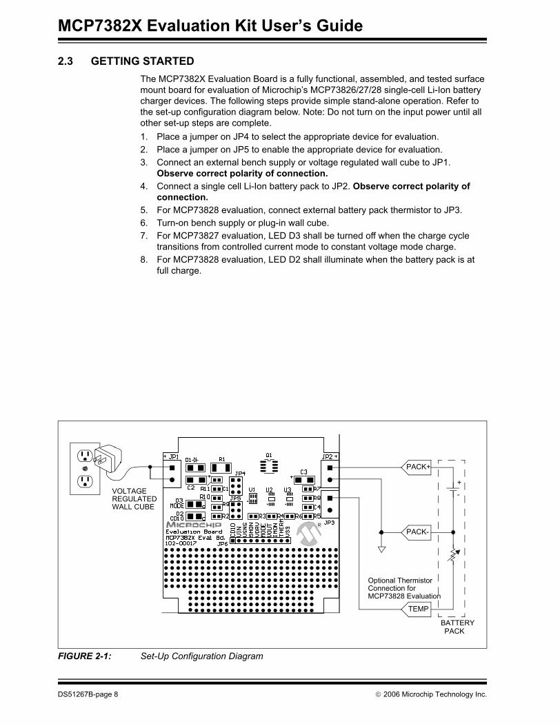
2.3 GETTING STARTEDThe MCP7382X Evaluation Board is a fully functional, assembled, and tested surface mount board for evaluation of Microchip’s MCP73826/27/28 single-cell Li-Ion battery charger devices. The following steps provide simple stand-alone operation. Refer to the set-up configuration diagram below. Note: Do not turn on the input power until all other set-up steps are complete.1. Place a jumper on JP4 to select the appropriate device for evaluation.2. Place a jumper on JP5 to enable the appropriate device for evaluation.3. Connect an external bench supply or voltage regulated wall cube to JP1.
Observe correct polarity of connection.4. Connect a single cell Li-Ion battery pack to JP2. Observe correct polarity of
connection.5. For MCP73828 evaluation, connect external battery pack thermistor to JP3.6. Turn-on bench supply or plug-in wall cube.7. For MCP73827 evaluation, LED D3 shall be turned off when the charge cycle
transitions from controlled current mode to constant voltage mode charge.8. For MCP73828 evaluation, LED D2 shall illuminate when the battery pack is at
full charge.
FIGURE 2-1: Set-Up Configuration Diagram
TEMP
PACK+
PACK-
+-
BATTERYPACK
Optional Thermistor Connection for MCP73828 Evaluation
VOLTAGE REGULATED WALL CUBE
DS51267B-page 8 © 2006 Microchip Technology Inc.
Installation and Operation
2.4 DETAILED DESCRIPTIONThe MCP7382X Evaluation Board is set-up to evaluate simple, stand-alone, linear charging of single cell Li-Ion battery packs. Each of the three Li-Ion battery chargers can be evaluated independently. The chargers provide controlled current charging fol-lowed by constant voltage charging. The MCP73826, U1, is provided in a 6-pin SOT23 package and is equipped with shutdown control. The MCP73827, U2, is provided in an 8-pin MSOP package. In addition to shutdown control, the MCP73827 signals when the charge cycle transitions from controlled current mode to constant voltage mode. An LED, D3, is illuminated during the controlled current mode. A voltage representation of the charge current, IMON, is provided for a host microcontroller to monitor the charge profile. The MCP73828, U3, is also provided in an 8-pin MSOP package. In addition to shutdown control, the MCP73828 signals when the charge current has diminished below ten percent of the peak charge current. An LED, D2, is illuminated indicating full charge. A thermistor input is provided to inhibit charging when the cell temperature is outside a pre-defined window. Refer to the appropriate data sheets for details on the individual device features.
2.4.1 Input SourceThe MCP7382X Evaluation Board is designed to provide an output current of 1A, typi-cal. A 5V ±10%, 6W input source should be utilized to power the evaluation kit. JP1 terminal 1 is the positive input source connection. JP1 terminal 2 is the negative input source connection.Higher or lower output currents can be obtained by adjusting the value of the sense resistor, R1. A corresponding higher or lower power input source may need to be uti-lized. Care should be taken not to over stress the pass transistor, Q1, with excessive power dissipation when higher output currents are desired.
2.4.2 Reverse Blocking ProtectionThe MCP7382X Evaluation Board is designed to provide reverse blocking protection in the event a reversed polarity input source is connected to JP1. The reverse blocking protection diode, D1, also ensures that a faulted or shorted input source will not adversely effect the battery pack.
2.4.3 Battery HeadersTwo headers, JP2 and JP3 are used to connect to an external Li-Ion battery pack and optional protection thermistor. JP2 terminal 1 is the battery pack positive connection, JP2 terminal 2 is the negative battery pack connection. JP3 terminal 1 is for connection to a 10 k ohm NTC thermistor situated in the battery pack for temperature sensing. JP3 terminal 2 is the negative reference for the thermistor.
Note: Improper connection of the battery may result in damage to the battery and the possibility of personal injury. It is also important to avoid shorting the battery terminals together.
© 2006 Microchip Technology Inc. DS51267B-page 9
MCP7382X Evaluation Kit User’s Guide
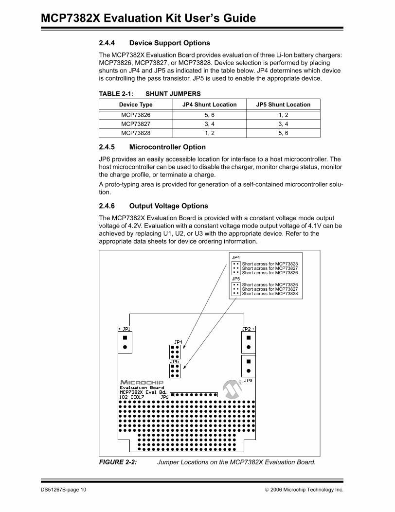
2.4.4 Device Support OptionsThe MCP7382X Evaluation Board provides evaluation of three Li-Ion battery chargers: MCP73826, MCP73827, or MCP73828. Device selection is performed by placing shunts on JP4 and JP5 as indicated in the table below. JP4 determines which device is controlling the pass transistor. JP5 is used to enable the appropriate device.
TABLE 2-1: SHUNT JUMPERS
2.4.5 Microcontroller OptionJP6 provides an easily accessible location for interface to a host microcontroller. The host microcontroller can be used to disable the charger, monitor charge status, monitor the charge profile, or terminate a charge.A proto-typing area is provided for generation of a self-contained microcontroller solu-tion.
2.4.6 Output Voltage OptionsThe MCP7382X Evaluation Board is provided with a constant voltage mode output voltage of 4.2V. Evaluation with a constant voltage mode output voltage of 4.1V can be achieved by replacing U1, U2, or U3 with the appropriate device. Refer to the appropriate data sheets for device ordering information.
FIGURE 2-2: Jumper Locations on the MCP7382X Evaluation Board.
Device Type JP4 Shunt Location JP5 Shunt Location
MCP73826 5, 6 1, 2MCP73827 3, 4 3, 4MCP73828 1, 2 5, 6
JP4Short across for MCP73828Short across for MCP73827Short across for MCP73826
JP5Short across for MCP73826Short across for MCP73827Short across for MCP73828
DS51267B-page 10 © 2006 Microchip Technology Inc.
MCP7382X EVALUATION KITUSER’S GUIDE
Appendix A. Schematic and Board Layouts
A.1 INTRODUCTIONThis appendix contains the schematic and board layouts for the MCP7382X Evaluation Kit.
A.2 HIGHLIGHTSDiagrams included in this appendix:• Board Schematic• Board Layout - Top Assembly• Board Layout - Top Layer• Board Layout - Bottom Layer
© 2006 Microchip Technology Inc. DS51267B-page 11
MCP7382X Evaluation Kit User’s Guide
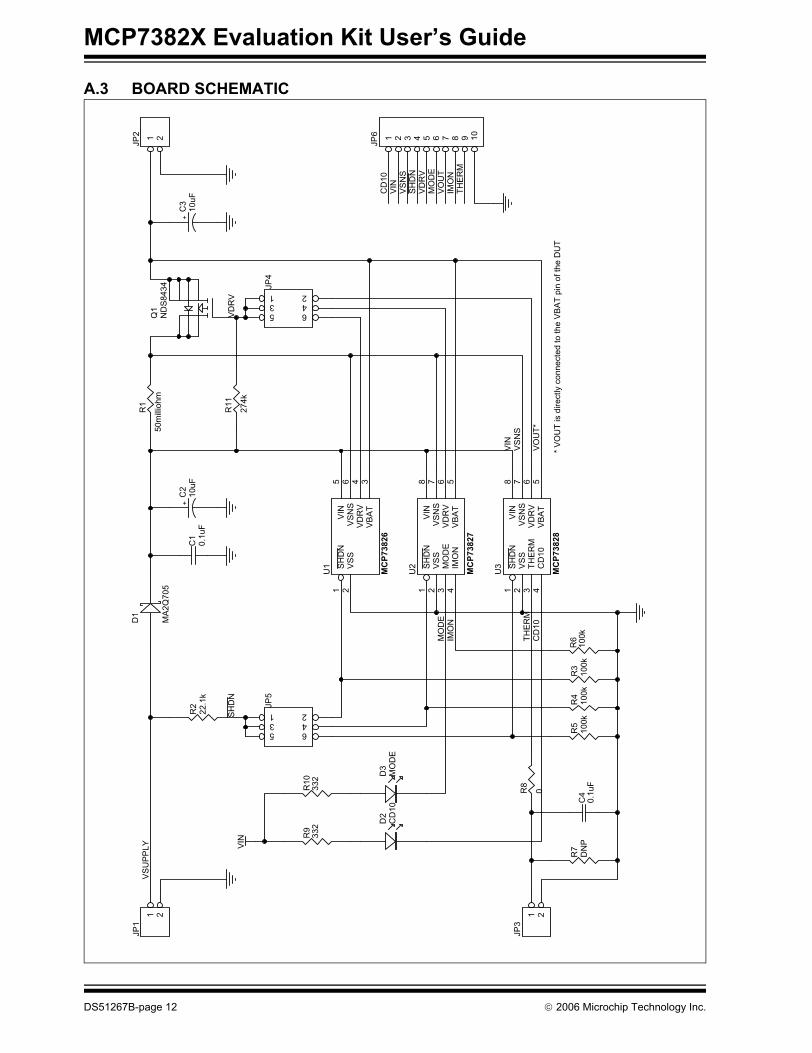
A.3 BOARD SCHEMATIC
C1
0.1
uF
+C
21
0u
F+
C3
10
uF
1 2
JP
1
1 2
JP
2
1 2
JP
3
R1
50m
illio
hm
Q1
ND
S8
43
4
D1
MA
2Q
705
1 23 45 6
JP
4
1 23 45 6
JP
5
R2
22.1
k
R3
100k
R4
100k
R5
100k
R7
DN
P
R8
0
VD
RV
4
VB
AT
3
SH
DN
1
VS
S2
VS
NS
6V
IN5
U1
MCP73826
VD
RV
6
VB
AT
5
SH
DN
1
IMO
N4
VS
S2
MO
DE
3V
SN
S7
VIN
8U
2
MCP73827
VD
RV
6
VB
AT
5
SH
DN
1
CD
10
4
VS
S2
TH
ER
M3
VS
NS
7V
IN8
U3
MCP73828
C4
0.1
uF
R6
100k
R9
33
2R
10
33
2
VIN
VS
NS
VO
UT
*
SH
DN
MO
DE
TH
ER
MC
D1
0
VD
RV
1 2 3 4 5 6 7 8 9 10
JP
6
IMO
N
VIN
VS
NS
VD
RV
VO
UT
SH
DN
MO
DE
IMO
NT
HE
RM
CD
10
VS
UP
PLY
D2
CD
10
D3
MO
DE
R1
1
274k
VIN
* V
OU
T is d
irectly c
onnecte
d to the V
BA
T p
in o
f th
e D
UT
DS51267B-page 12 © 2006 Microchip Technology Inc.
Schematic and Board Layouts
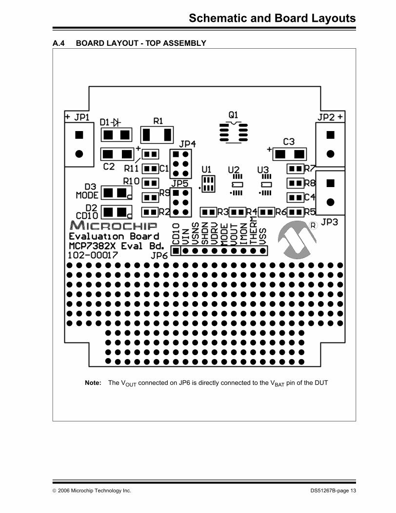
A.4 BOARD LAYOUT - TOP ASSEMBLY
Note: The VOUT connected on JP6 is directly connected to the VBAT pin of the DUT
© 2006 Microchip Technology Inc. DS51267B-page 13
MCP7382X Evaluation Kit User’s Guide
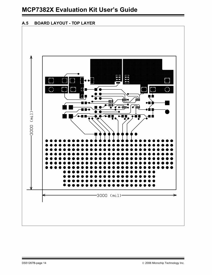
A.5 BOARD LAYOUT - TOP LAYER
DS51267B-page 14 © 2006 Microchip Technology Inc.
Schematic and Board Layouts
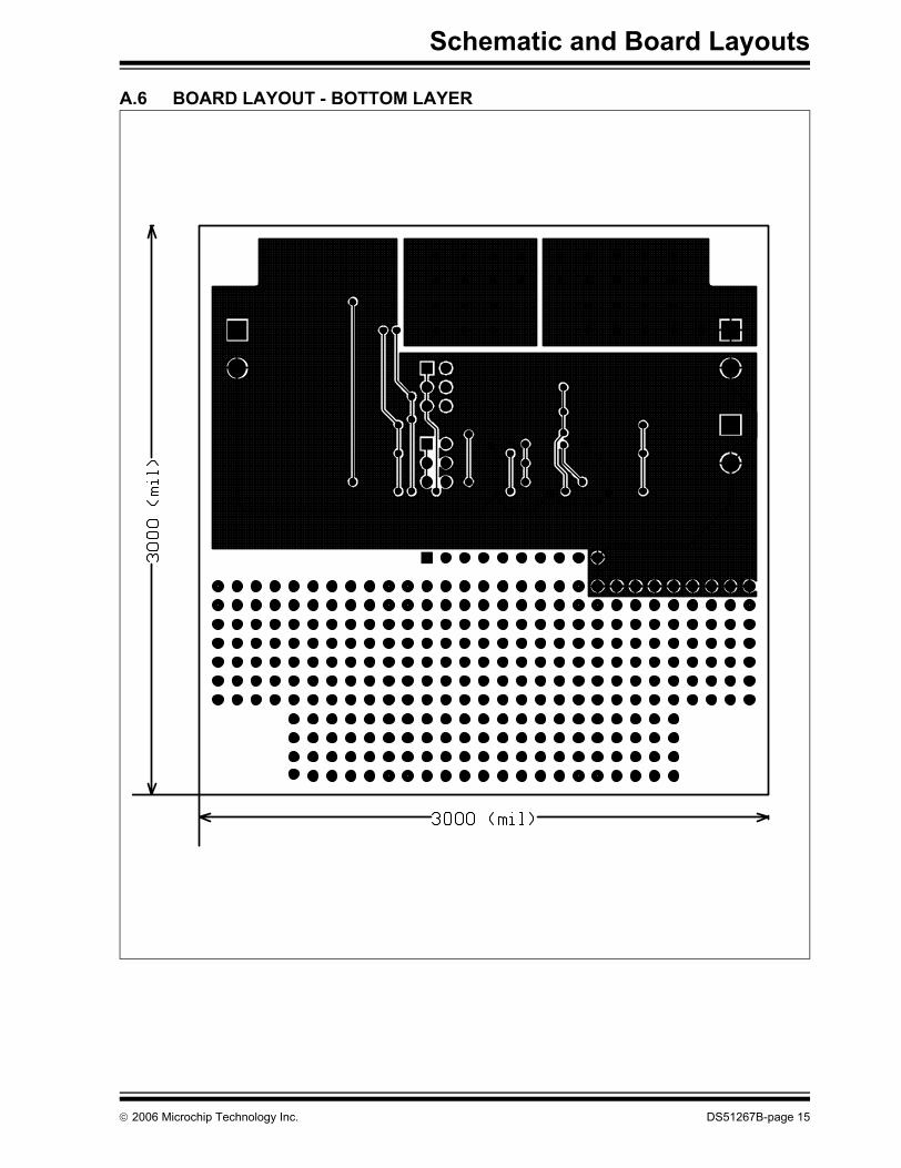
A.6 BOARD LAYOUT - BOTTOM LAYER
© 2006 Microchip Technology Inc. DS51267B-page 15

MCP7382X Evaluation Kit User’s Guide
NOTES:
DS51267B-page 16 © 2006 Microchip Technology Inc.
MCP7382X EVALUATION KITUSER’S GUIDE
Appendix B. Bill Of Materials (BOM)
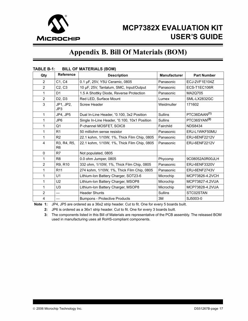
TABLE B-1: BILL OF MATERIALS (BOM)Qty Reference Description Manufacturer Part Number
2 C1, C4 0.1 µF, 25V, Y5U Ceramic, 0805 Panasonic ECJ-2VF1E104Z2 C2, C3 10 µF, 25V, Tantalum, SMC, Input/Output Panasonic ECS-T1EC106R1 D1 1.5 A Shottky Diode, Reverse Protection Panasonic MA2Q7052 D2, D3 Red LED, Surface Mount Lumex SML-LX2832GC3 JP1, JP2,
JP3Screw Header Weidmuller 171602
1 JP4, JP5 Dual In-Line Header, “0.100, 3x2 Position Sullins PTC36DAAN(1)
1 JP6 Single In-Line Header, “0.100, 10x1 Position Sullins PTC36SYAN(2)
1 Q1 P-channel MOSFET, SOIC8 Fairchild NDS84341 R1 50 milliohm sense resistor Panasonic ERJ-L1WKF50MU1 R2 22.1 kohm, 1/10W, 1%, Thick Film Chip, 0805 Panasonic ERJ-6ENF2212V4 R3, R4, R5,
R622.1 kohm, 1/10W, 1%, Thick Film Chip, 0805 Panasonic ERJ-6ENF2212V
0 R7 Not populated, 08051 R8 0.0 ohm Jumper, 0805 Phycomp 9C08052A0R00JLH2 R9, R10 332 ohm, 1/10W, 1%, Thick Film Chip, 0805 Panasonic ERJ-6ENF3320V1 R11 274 kohm, 1/10W, 1%, Thick Film Chip, 0805 Panasonic ERJ-6ENF2743V1 U1 Lithium-Ion Battery Charger, SOT23-6 Microchip MCP73826-4.2VCH1 U2 Lithium-Ion Battery Charger, MSOP8 Microchip MCP73827-4.2VUA1 U3 Lithium-Ion Battery Charger, MSOP8 Microchip MCP73828-4.2VUA2 — Header Shunts Sullins STC02STAN4 — Bumpons - Protective Products 3M SJ5003-0
Note 1: JP4, JP5 are ordered as a 36x2 strip header. Cut to fit. One for every 5 boards built.2: JP6 is ordered as a 36x1 strip header. Cut to fit. One for every 3 boards built.3: The components listed in this Bill of Materials are representative of the PCB assembly. The released BOM
used in manufacturing uses all RoHS-compliant components.
© 2006 Microchip Technology Inc. DS51267B-page 17
DS51267B-page 18 © 2006 Microchip Technology Inc.
AMERICASCorporate Office2355 West Chandler Blvd.Chandler, AZ 85224-6199Tel: 480-792-7200 Fax: 480-792-7277Technical Support: http://support.microchip.comWeb Address: www.microchip.comAtlantaAlpharetta, GA Tel: 770-640-0034 Fax: 770-640-0307BostonWestborough, MA Tel: 774-760-0087 Fax: 774-760-0088ChicagoItasca, IL Tel: 630-285-0071 Fax: 630-285-0075DallasAddison, TX Tel: 972-818-7423 Fax: 972-818-2924DetroitFarmington Hills, MI Tel: 248-538-2250Fax: 248-538-2260KokomoKokomo, IN Tel: 765-864-8360Fax: 765-864-8387Los AngelesMission Viejo, CA Tel: 949-462-9523 Fax: 949-462-9608Santa ClaraSanta Clara, CA Tel: 408-961-6444Fax: 408-961-6445TorontoMississauga, Ontario, CanadaTel: 905-673-0699 Fax: 905-673-6509
ASIA/PACIFICAsia Pacific OfficeSuites 3707-14, 37th FloorTower 6, The GatewayHabour City, KowloonHong KongTel: 852-2401-1200Fax: 852-2401-3431Australia - SydneyTel: 61-2-9868-6733Fax: 61-2-9868-6755China - BeijingTel: 86-10-8528-2100 Fax: 86-10-8528-2104China - ChengduTel: 86-28-8676-6200 Fax: 86-28-8676-6599China - FuzhouTel: 86-591-8750-3506 Fax: 86-591-8750-3521China - Hong Kong SARTel: 852-2401-1200 Fax: 852-2401-3431China - QingdaoTel: 86-532-8502-7355Fax: 86-532-8502-7205China - ShanghaiTel: 86-21-5407-5533 Fax: 86-21-5407-5066China - ShenyangTel: 86-24-2334-2829Fax: 86-24-2334-2393China - ShenzhenTel: 86-755-8203-2660 Fax: 86-755-8203-1760China - ShundeTel: 86-757-2839-5507 Fax: 86-757-2839-5571China - WuhanTel: 86-27-5980-5300Fax: 86-27-5980-5118China - XianTel: 86-29-8833-7250Fax: 86-29-8833-7256
ASIA/PACIFICIndia - BangaloreTel: 91-80-4182-8400 Fax: 91-80-4182-8422India - New DelhiTel: 91-11-4160-8631Fax: 91-11-4160-8632India - PuneTel: 91-20-2566-1512Fax: 91-20-2566-1513Japan - YokohamaTel: 81-45-471- 6166 Fax: 81-45-471-6122Korea - GumiTel: 82-54-473-4301Fax: 82-54-473-4302Korea - SeoulTel: 82-2-554-7200Fax: 82-2-558-5932 or 82-2-558-5934Malaysia - PenangTel: 60-4-646-8870Fax: 60-4-646-5086Philippines - ManilaTel: 63-2-634-9065Fax: 63-2-634-9069SingaporeTel: 65-6334-8870Fax: 65-6334-8850Taiwan - Hsin ChuTel: 886-3-572-9526Fax: 886-3-572-6459Taiwan - KaohsiungTel: 886-7-536-4818Fax: 886-7-536-4803Taiwan - TaipeiTel: 886-2-2500-6610 Fax: 886-2-2508-0102Thailand - BangkokTel: 66-2-694-1351Fax: 66-2-694-1350
EUROPEAustria - WelsTel: 43-7242-2244-3910Fax: 43-7242-2244-393Denmark - CopenhagenTel: 45-4450-2828 Fax: 45-4485-2829France - ParisTel: 33-1-69-53-63-20 Fax: 33-1-69-30-90-79Germany - MunichTel: 49-89-627-144-0 Fax: 49-89-627-144-44Italy - Milan Tel: 39-0331-742611 Fax: 39-0331-466781Netherlands - DrunenTel: 31-416-690399 Fax: 31-416-690340Spain - MadridTel: 34-91-708-08-90Fax: 34-91-708-08-91UK - WokinghamTel: 44-118-921-5869Fax: 44-118-921-5820
WORLDWIDE SALES AND SERVICE
07/21/06