Embed Size (px)
Citation preview
McQuay® Water Heating & High Capacity Booster Coils
Types HI-F5 & E-F5
Catalog 412-6

HI-F5 & E-F5 water heating and high capacity booster coils
SelectTOOLSTM for Contractor CoilsMcQuay offers a wide variety of standard fin spacings, rowand circuiting combinations. For optimum coil selection,McQuay's SelectTOOLSTM for Contractor Coils selection pro-gram makes it easy to select the most economical standardor special application coil to meet your job requirements.
Contact your local McQuay representative for a coil selectionthat meets the most exacting specification.
ContentsSelectTOOLSTM..................................................................3ARI certification..................................................................3Nomenclature ....................................................................4Standard availability chart ..................................................5Circuiting arrangements.....................................................6Design features..................................................................7General specifications — 5W & 5B coils............................8Application recommendations............................................9Cleanable coils ..................................................................9Sample coil selection .......................................................10
ARI certificationMcQuay® water heating andbooster coils are certified inaccordance with the forced circu-lation air cooling and air heatingcoil certification program, whichis based on ARI Standard 410.
Note: Special application coils may be outside the scope ofARI Standard 410.
Conversion of air volume to standard air .........................11General formulas..............................................................12Heat transfer values Mt ..............................................13, 14Hl-F5 selection data heat transfer values, Rf .............15, 16E-F5 selection data heat transfer values, Rf .................... 17Air pressure drop.............................................................. 18Water pressure drop .............................................. 19,20,21Dimensional data, HI-F5 & E-F5 coils ............ 22, 23, 24, 25Dimensional data, booster coils, 5B...................... 26,27,28Engineering guide specifications..................................... 29
“McQuay" and "HI-F" are registered trademarks of McQuay International, Minneapolis, MN.
The McQuay HI-F fin surface is covered by U.S. Patent No. 3,645,330.
Copyright ©2006 McQuay International. All rights reserved throughout the world.
Bulletin illustrations cover the general appearance of McQuay International products at time of publicationand we reserve the right to make changes in design and construction at any time without notice.
McQuay Catalog 412-6 3
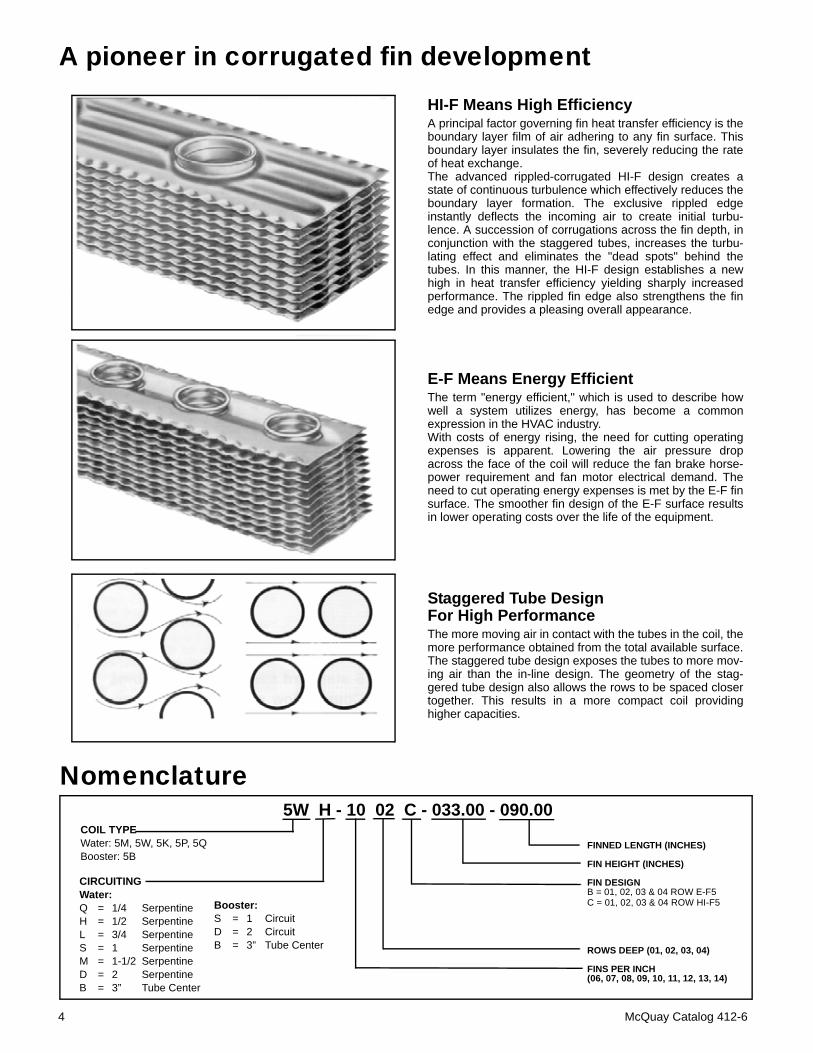
A pioneer in corrugated fin developmentHI-F Means High EfficiencyA principal factor governing fin heat transfer efficiency is theboundary layer film of air adhering to any fin surface. Thisboundary layer insulates the fin, severely reducing the rateof heat exchange.The advanced rippled-corrugated HI-F design creates astate of continuous turbulence which effectively reduces theboundary layer formation. The exclusive rippled edgeinstantly deflects the incoming air to create initial turbu-lence. A succession of corrugations across the fin depth, inconjunction with the staggered tubes, increases the turbu-lating effect and eliminates the "dead spots" behind thetubes. In this manner, the HI-F design establishes a newhigh in heat transfer efficiency yielding sharply increasedperformance. The rippled fin edge also strengthens the finedge and provides a pleasing overall appearance.
E-F Means Energy EfficientThe term "energy efficient," which is used to describe howwell a system utilizes energy, has become a commonexpression in the HVAC industry.With costs of energy rising, the need for cutting operatingexpenses is apparent. Lowering the air pressure dropacross the face of the coil will reduce the fan brake horse-power requirement and fan motor electrical demand. Theneed to cut operating energy expenses is met by the E-F finsurface. The smoother fin design of the E-F surface resultsin lower operating costs over the life of the equipment.
Staggered Tube Design For High Performance The more moving air in contact with the tubes in the coil, themore performance obtained from the total available surface.The staggered tube design exposes the tubes to more mov-ing air than the in-line design. The geometry of the stag-gered tube design also allows the rows to be spaced closertogether. This results in a more compact coil providinghigher capacities.
Nomenclature5W H - 10 02 C - 033.00 - 090.00
COIL TYPEWater: 5M, 5W, 5K, 5P, 5QBooster: 5B
CIRCUITINGWater:Q = 1/4 SerpentineH = 1/2 SerpentineL = 3/4 SerpentineS = 1 SerpentineM = 1-1/2 SerpentineD = 2 SerpentineB = 3” Tube Center
Booster:S = 1 CircuitD = 2 CircuitB = 3” Tube Center
FINNED LENGTH (INCHES)
FIN HEIGHT (INCHES)
FIN DESIGNB = 01, 02, 03 & 04 ROW E-F5C = 01, 02, 03 & 04 ROW HI-F5
ROWS DEEP (01, 02, 03, 04)
FINS PER INCH(06, 07, 08, 09, 10, 11, 12, 13, 14)
4 McQuay Catalog 412-6
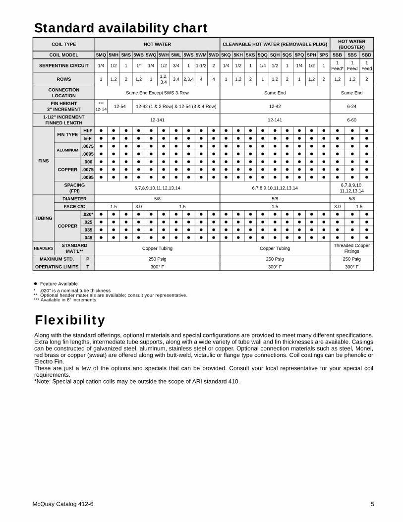
Standard availability chart
Feature Available
COIL TYPE HOT WATER CLEANABLE HOT WATER (REMOVABLE PLUG) HOT WATER(BOOSTER)
COIL MODEL 5MQ 5MH 5MS 5WB 5WQ 5WH 5WL 5WS 5WM 5WD 5KQ 5KH 5KS 5QQ 5QH 5QS 5PQ 5PH 5PS 5BB 5BS 5BD
SERPENTINE CIRCUIT 1/4 1/2 1 1* 1/4 1/2 3/4 1 1-1/2 2 1/4 1/2 1 1/4 1/2 1 1/4 1/2 1 1 Feed*
1 Feed
1 Feed
ROWS 1 1,2 2 1,2 1 1,2,3,4 3,4 2,3,4 4 4 1 1,2 2 1 1,2 2 1 1,2 2 1,2 1,2 2
CONNECTIONLOCATION Same End Except 5WS 3-Row Same End Same End
FIN HEIGHT3" INCREMENT
*** 12- 54
12-54 12-42 (1 & 2 Row) & 12-54 (3 & 4 Row) 12-42 6-24
1-1/2" INCREMENTFINNED LENGTH 12-141 12-141 6-60
FINS
FIN TYPEHI-FE-F
ALUMINUM.0075.0095
COPPER.006.0075.0095
SPACING(FPI) 6,7,8,9,10,11,12,13,14 6,7,8,9,10,11,12,13,14 6,7,8,9,10,
11,12,13,14
TUBING
DIAMETER 5/8 5/8 5/8
FACE C/C 1.5 3.0 1.5 1.5 3.0 1.5
COPPER
.020*.025.035.049
HEADERS STANDARD MAT'L** Copper Tubing Copper Tubing Threaded Copper
Fittings
MAXIMUM STD. P 250 Psig 250 Psig 250 Psig
OPERATING LIMITS T 300° F 300° F 300° F
Flexibility
* .020” is a nominal tube thickness** Optional header materials are available; consult your representative.*** Available in 6” increments.
Along with the standard offerings, optional materials and special configurations are provided to meet many different specifications.Extra long fin lengths, intermediate tube supports, along with a wide variety of tube wall and fin thicknesses are available. Casingscan be constructed of galvanized steel, aluminum, stainless steel or copper. Optional connection materials such as steel, Monel,red brass or copper (sweat) are offered along with butt-weld, victaulic or flange type connections. Coil coatings can be phenolic orElectro Fin.These are just a few of the options and specials that can be provided. Consult your local representative for your special coilrequirements.*Note: Special application coils may be outside the scope of ARI standard 410.
McQuay Catalog 412-6 5
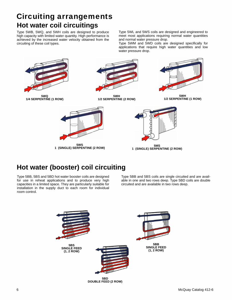
Hot water (booster) coil circuitingType 5BB, 5BS and 5BD hot water booster coils are designedfor use in reheat applications and to produce very highcapacities in a limited space. They are particularly suitable forinstallation in the supply duct to each room for individualroom control.
Type 5BB and 5BS coils are single circuited and are avail-able in one and two rows deep. Type 5BD coils are doublecircuited and are available in two rows deep.
5BDDOUBLE FEED (2 ROW)
Hot water coil circuitingsType 5WB, 5WQ, and 5WH coils are designed to producehigh capacity with limited water quantity. High performance isachieved by the increased water velocity obtained from thecircuiting of these coil types.
Circuiting arrangements
Type 5WL and 5WS coils are designed and engineered tomeet most applications requiring normal water quantitiesand normal water pressure drop.Type 5WM and 5WD coils are designed specifically forapplications that require high water quantities and lowwater pressure drop.
5WQ1/4 SERPENTINE (1 ROW)
5WH1/2 SERPENTINE (2 ROW)
5WH1/2 SERPENTINE (1 ROW)
5WS1 (SINGLE) SERPENTINE (2 ROW)
5MS1 (SINGLE) SERPENTINE (2 ROW)
5BBSINGLE FEED
(1, 2 ROW)5BS
SINGLE FEED (1, 2 ROW)
6 McQuay Catalog 412-6
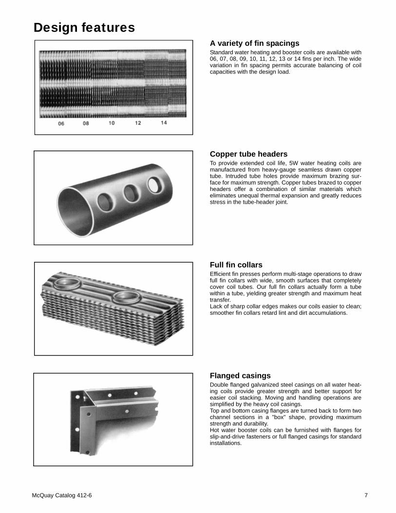
Design featuresA variety of fin spacingsStandard water heating and booster coils are available with06, 07, 08, 09, 10, 11, 12, 13 or 14 fins per inch. The widevariation in fin spacing permits accurate balancing of coilcapacities with the design load.
Copper tube headersTo provide extended coil life, 5W water heating coils aremanufactured from heavy-gauge seamless drawn coppertube. Intruded tube holes provide maximum brazing sur-face for maximum strength. Copper tubes brazed to copperheaders offer a combination of similar materials whicheliminates unequal thermal expansion and greatly reducesstress in the tube-header joint.
Full fin collarsEfficient fin presses perform multi-stage operations to drawfull fin collars with wide, smooth surfaces that completelycover coil tubes. Our full fin collars actually form a tubewithin a tube, yielding greater strength and maximum heattransfer.Lack of sharp collar edges makes our coils easier to clean;smoother fin collars retard lint and dirt accumulations.
Flanged casingsDouble flanged galvanized steel casings on all water heat-ing coils provide greater strength and better support foreasier coil stacking. Moving and handling operations aresimplified by the heavy coil casings.Top and bottom casing flanges are turned back to form twochannel sections in a "box" shape, providing maximumstrength and durability.Hot water booster coils can be furnished with flanges forslip-and-drive fasteners or full flanged casings for standardinstallations.
McQuay Catalog 412-6 7
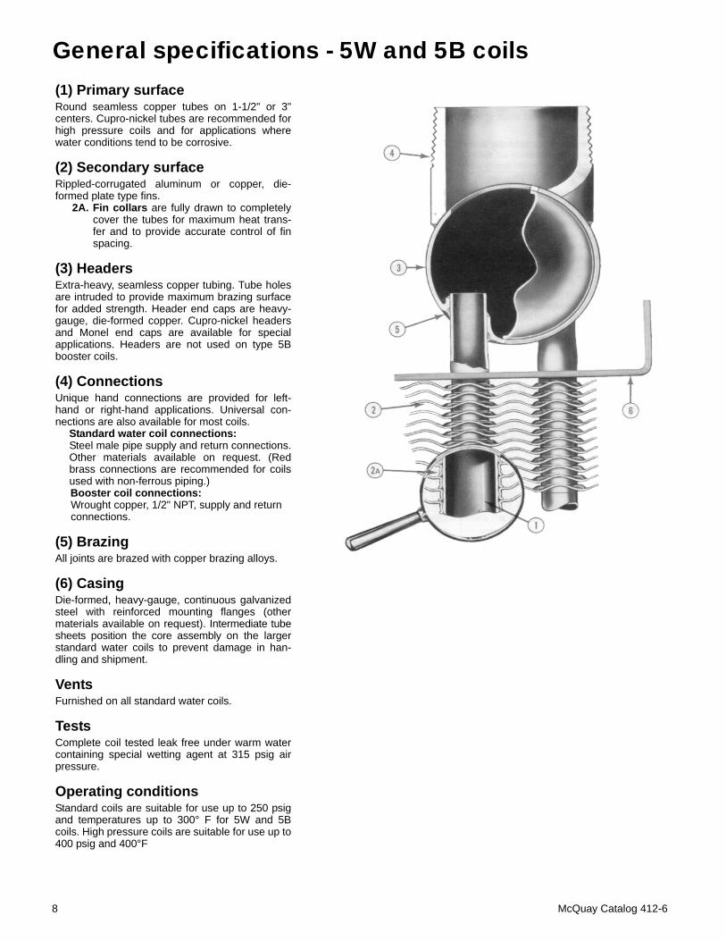
General specifications - 5W and 5B coils(1) Primary surfaceRound seamless copper tubes on 1-1/2" or 3"centers. Cupro-nickel tubes are recommended forhigh pressure coils and for applications wherewater conditions tend to be corrosive.
(2) Secondary surfaceRippled-corrugated aluminum or copper, die-formed plate type fins.
2A. Fin collars are fully drawn to completelycover the tubes for maximum heat trans-fer and to provide accurate control of finspacing.
(3) HeadersExtra-heavy, seamless copper tubing. Tube holesare intruded to provide maximum brazing surfacefor added strength. Header end caps are heavy-gauge, die-formed copper. Cupro-nickel headersand Monel end caps are available for specialapplications. Headers are not used on type 5Bbooster coils.
(4) ConnectionsUnique hand connections are provided for left-hand or right-hand applications. Universal con-nections are also available for most coils.
Standard water coil connections: Steel male pipe supply and return connections.Other materials available on request. (Redbrass connections are recommended for coilsused with non-ferrous piping.)Booster coil connections: Wrought copper, 1/2" NPT, supply and return connections.
(5) BrazingAll joints are brazed with copper brazing alloys.
(6) CasingDie-formed, heavy-gauge, continuous galvanizedsteel with reinforced mounting flanges (othermaterials available on request). Intermediate tubesheets position the core assembly on the largerstandard water coils to prevent damage in han-dling and shipment.
VentsFurnished on all standard water coils.
TestsComplete coil tested leak free under warm watercontaining special wetting agent at 315 psig airpressure.
Operating conditionsStandard coils are suitable for use up to 250 psigand temperatures up to 300° F for 5W and 5Bcoils. High pressure coils are suitable for use up to400 psig and 400°F
8 McQuay Catalog 412-6
Application recommendations1. Piping should be in accordance with accepted indus-
try standards.
2. When drainable coils are desired, tubes should beinstalled in a horizontal position. Use a spirit level. Ifthe tubes cannot be installed level, special drainheaders are available on request.
3. Connect the water supply to the leaving air side andthe water return to the entering air side of the coil.Connecting the supply and/or return in any othermanner will result in a reduced performance.
4. Hot water coils are not normally recommended foruse with entering air temperatures below 40° F;however, special high pressure water coils havebeen used very successfully on high temperaturehot water jobs with low entering air temperatureswhen correctly controlled. No control system can bedepended on to be 100% safe against freeze-upwith water coils. Glycol solutions or brines are theonly freeze-safe media for operation of water coilsfor low entering air conditions.
5. When fresh and return air are to be heated by a hotwater coil, care should be used in the design of theductwork to provide thorough mixing before the airenters the coil.The return air should always enter the bottom of theduct. Fresh air should enter the top of the duct. Thegreater the distance between the point of mixing andentrance to the coil, the better the application.
Temperature control elements should be locatedto sense the lowest temperature air that will enterthe coil.Always install gasketed fresh air dampers whichare automatically controlled to close whenever thewater leaving the coil is too cool, or the fan stops.Care should be used in designing fresh air intakesto prevent stack effect (or wind) from forcing coldair through the coils when the fan is shut down.Two sets of dampers are frequently required. Con-tinuous water circulation through the coils at alltimes is recommended when fresh air mixtures areused.Face and bypass dampers are recommended inpreference to valves for controlling leaving air tem-perature from hot water coils used to heat fresh airmixtures.
6. Two-position or modulating valves can be used tocontrol hot water coils on booster applications.Follow standard recommendations of the controlmanufacturer regarding sizing of valves and loca-tion of temperature controllers for these applica-tions.
7. Pipe sizes for the system must be selected on thebasis of the head (pressure) available from the cir-culating pump. It is recommended that the velocityshould not generally exceed 8 feet per second andthat the pressure drop should be approximately 3feet of water per 100 feet of pipe.
Hl-F5 vs. E-F5 coilsTwo different coil fin surfaces are offered. This results in a more economical coil selection for a given application.
Type. Tube Dia. Fin Type Application
Hl-F5 5/8” HI-F Hi-Efficiency
Gives highest heat transfer rate for a given amount of surface.
E-F5 5/8” E-F Energy
Efficiency
Smoother fin corrugation than the Hl-F5 results in a lower air pressure drop and lower fan bhp requirements. The cost of additional surface can be amortized by the kw savings.
Cleanable coils5W type water coils are also offered in a cleanable tube con-figuration. The cleanable coils are identical to 5W coils withthe addition of removable plugs in the header(s) to facilitatetube cleaning. Type 5PQ, 5PH and 5PS coils have removableplugs on the coil connection end only.
Type 5QQ, 5QH and 5QS coils have removable plugs onthe opposite connection end only. 5K, 5P and 5Q 1-rowand 2-row cleanable water heating coils may be outside thescope of ARI standard 410.
McQuay Catalog 412-6 9
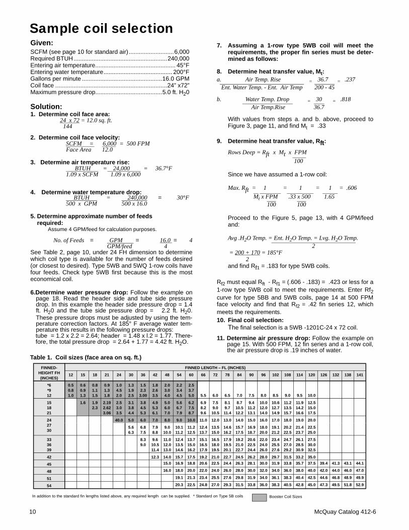
Sample coil selectionGiven:SCFM (see page 10 for standard air) ...........................6,000Required BTUH........................................................240,000Entering air temperature................................................ 45°FEntering water temperature......................................... 200°FGallons per minute ................................................16.0 GPMCoil face ...................................................................24” x72”Maximum pressure drop........................................5.0 ft. H20
Solution:1. Determine coil face area:
24 x 72 = 12.0 sq. ft. 144
2. Determine coil face velocity:SCFM = 6,000 = 500 FPMFace Area 12.0
3. Determine air temperature rise: BTUH = 24,000 = 36.7°F1.09 x SCFM 1.09 x 6,000
4. Determine water temperature drop: BTUH = 240,000 = 30°F500 x GPM 500 x 16.0
5. Determine approximate number of feeds required:
Assume 4 GPM/feed for calculation purposes.
No. of Feeds = GPM = 16.0 = 4 GPM/feed 4 See Table 2, page 10, under 24 FH dimension to determinewhich coil type is available for the number of feeds desired(or closest to desired). Type 5WB and 5WQ 1-row coils havefour feeds. Check type 5WB first because this is the mosteconomical coil.
6.Determine water pressure drop: Follow the example onpage 18. Read the header side and tube side pressuredrop. In this example the header side pressure drop = 1.4ft. H20 and the tube side pressure drop = 2.2 ft. H20.These pressure drops must be adjusted by using the tem-perature correction factors. At 185° F average water tem-perature this results in the following pressure drops:tube = 1.2 x 2.2 = 2.64; header = 1.48 x l.2 = 1.77. There-fore, the total pressure drop = 2.64 + 1.77 = 4.42 ft. H2O.
7. Assuming a 1-row type 5WB coil will meet therequirements, the proper fin series must be deter-mined as follows:
8. Determine heat transfer value, Mt:a. Air Temp. Rise = 36.7 = .237 Ent. Water Temp. - Ent. Air Temp 200 - 45
b. Water Temp. Drop = 30 = .818 Air Temp.Rise 36.7
With values from steps a. and b. above, proceed toFigure 3, page 11, and find Mt = .33
9. Determine heat transfer value, Rft: Rows Deep = Rft x Mt x FPM 100
Since we have assumed a 1-row coil:
Max. Rft = 1 = 1 = 1 = .606 Mt x FPM .33 x 500 1.65 100 100
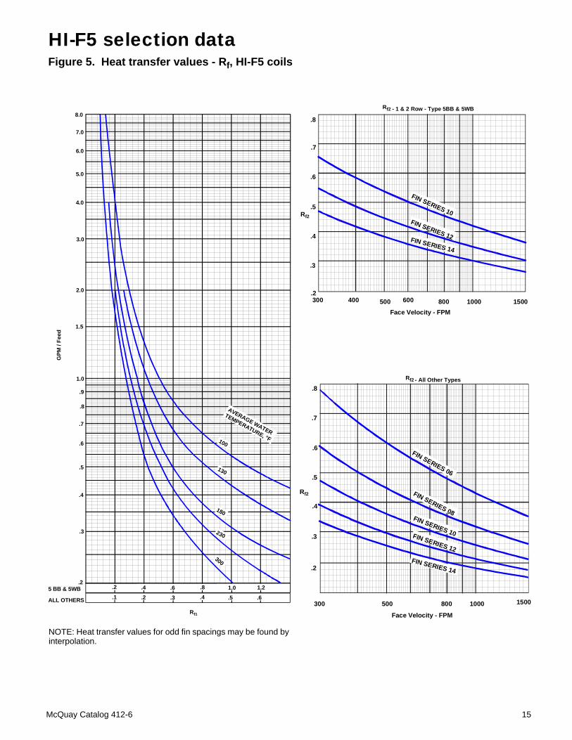
Proceed to the Figure 5, page 13, with 4 GPM/feedand:
Avg .H2O Temp. = Ent. H2O Temp. = Lvg. H2O Temp. 2 = 200 + 170 = 185°F 2and find Rf1 = .183 for type 5WB coils.
Rf2 must equal Rft - Rf1 = (.606 - .183) = .423 or less for a1-row type 5WB coil to meet the requirements. Enter Rf2curve for type 5BB and 5WB coils, page 14 at 500 FPMface velocity and find that Rf2 = .42 fin series 12, whichmeets the requirements.10. Final coil selection:
The final selection is a 5WB -1201C-24 x 72 coil.
11. Determine air pressure drop: Follow the example onpage 15. With 500 FPM, 12 fin series and a 1-row coil,the air pressure drop is .19 inches of water.
Table 1. Coil sizes (face area on sq. ft.)FINNED-
HEIGHT FH (INCHES)
FINNED LENGTH – FL (INCHES)
12 15 18 21 24 30 36 42 48 54 60 66 72 78 84 90 96 102 108 114 120 126 132 138 141
*6*912
0.5 0.8 1.0
0.60.91.3
0.81.11.5
0.91.31.8
1.04.52.0
1.31.92.5
1.52.33.00
1.82.63.5
2.03.04.0
2.23.44.5
2.53.75.0 5.5 6.0 6.5 7.0 7.5 8.0 8.5 9.0 9.5 10.0
151821
1.6 1.92.3
2.192.623.06
2.53.03.5
3.13.84.4
3.84.55.3
4.95.36.1
5.06.07.0
5.66.77.9
6.27.58.7
6.98.29.6
7.59.0
10.5
8.19.711.4
8.710.512.2
9.411.213.1
10.012.014.0
10.612.714.9
11.213.515.7
11.914.216.6
12.515.017.5
242730
40.0 5.0 6.0 7.0 8.0 9.0 10.0 11.0 12.0 13.0 14.0 15.0 16.0 17.0 18.0 19.0 20.0
5.66.3
6.87.5
7.98.8
9.010.0
10.111.2
11.212.5
12.413.7
13.515.0
14.616.2
15.717.5
16.918.7
18.020.0
19.121.2
20.222.5
21.423.7
22.525.0
333639
8.39.0
9.610.511.4
11.012.013.0
12.413.514.6
13.715.016.2
15.116.517.9
16.518.019.5
17.919.520.1
19.221.022.7
20.622.524.4
22.024.026.0
23.425.527.6
24.727.029.2
26.128.530.9
27.530.032.5
42 12.3 14.0 15.7 17.5 19.2 21.0 22.7 24.5 26.2 28.0 29.7 31.5 33.2 35.0
45 15.0 16.9 18.8 20.6 22.5 24.4 26.3 28.1 30.0 31.9 33.8 35.7 37.5 39.4 41.3 43.1 44.1
48 16.0 18.0 20.0 22.0 24.0 26.0 28.0 30.0 32.0 34.0 36.0 38.0 40.0 42.0 44.0 46.0 47.0
51 19.1 21.3 23.4 25.5 27.6 29.8 31.9 34.0 36.1 38.3 40.4 42.5 44.6 46.8 48.9 49.9
54 20.3 22.5 24.8 27.0 29.3 31.5 33.8 36.0 38.3 40.5 42.8 45.0 47.3 49.5 51.8 52.9
In addition to the standard fin lengths listed above, any required length can be supplied. * Standard on Type 5B coils Booster Coil Sizes
10 McQuay Catalog 412-6
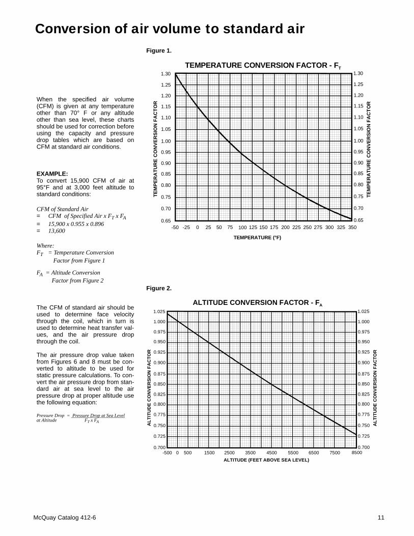
Conversion of air volume to standard air
When the specified air volume(CFM) is given at any temperatureother than 70° F or any altitudeother than sea level, these chartsshould be used for correction beforeusing the capacity and pressuredrop tables which are based onCFM at standard air conditions.
EXAMPLE:To convert 15,900 CFM of air at95°F and at 3,000 feet altitude tostandard conditions:
CFM of Standard Air= CFM of Specified Air x FT x FA= 15,900 x 0.955 x 0.896= 13,600
Where:FT = Temperature Conversion Factor from Figure 1
FA = Altitude Conversion Factor from Figure 2
The CFM of standard air should beused to determine face velocitythrough the coil, which in turn isused to determine heat transfer val-ues, and the air pressure dropthrough the coil.
The air pressure drop value takenfrom Figures 6 and 8 must be con-verted to altitude to be used forstatic pressure calculations. To con-vert the air pressure drop from stan-dard air at sea level to the airpressure drop at proper altitude usethe following equation:
Pressure Drop = Pressure Drop at Sea Levelat Altitude FT x FA
1.30
1.25
1.20
1.15
1.10
1.05
1.00
0.95
0.90
0.85
0.80
0.75
0.70
0.65
1.30
1.25
1.20
1.15
1.10
1.05
1.00
0.95
0.90
0.85
0.80
0.75
0.70
0.65-50 -25 0 25 50 75 100 125 150 175 200 225 250 275 300 325 350
TEMPERATURE (°F)
TEM
PER
ATU
RE
CO
NVE
RSI
ON
FA
CTO
R
TEM
PER
ATU
RE
CO
NVE
RSI
ON
FA
CTO
R
TEMPERATURE CONVERSION FACTOR - FT
1.025
1.000
0.975
0.950
0.925
0.900
0.875
0.850
0.825
0.800
0.775
0.750
0.725
0.700
ALT
ITU
DE
CO
NVE
RSI
ON
FA
CTO
R
ALTITUDE (FEET ABOVE SEA LEVEL)
ALTITUDE CONVERSION FACTOR - FA1.025
1.000
0.975
0.950
0.925
0.900
0.875
0.850
0.825
0.800
0.775
0.750
0.725
0.700
ALT
ITU
DE
CO
NVE
RSI
ON
FA
CTO
R
-500 0 500 1500 2500 3500 4500 5500 6500 7500 8500
Figure 1.
Figure 2.
McQuay Catalog 412-6 11
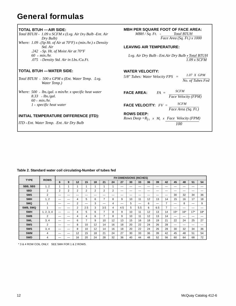
General formulasMBH PER SQUARE FOOT OF FACE AREA:
MBH / Sq. Ft. = Total BTUHFace Area (Sq. Ft.) x 1000
LEAVING AIR TEMPERATURE:
Lvg. Air Dry Bulb = Ent.Air Dry Bulb + Total BTUH1.09 x SCFM
WATER VELOCITY:5/8" Tubes: Water Velocity FPS = 1.07 X GPM
No. of Tubes Fed
FACE AREA: FA = SCFM
Face Velocity (FPM)
FACE VELOCITY: FV = SCFM
Face Area (Sq. Ft.)ROWS DEEP:Rows Deep =Rf t x Mt x Face Velocity (FPM) 100
TOTAL BTUH — AIR SIDE:Total BTUH = 1.09 x SCFM x (Lvg. Air Dry Bulb -Ent. Air
Dry Bulb)Where: 1.09 = (Sp Ht. of Air at 70°F) x (min./hr.) x Density
Std. Air.242 = Sp. Ht. of Moist Air at 70°F60 = min./hr..075 = Density Std. Air in Lbs./Cu.Ft.
TOTAL BTUH — WATER SIDE:
Total BTUH = 500 x GPM x (Ent. Water Temp. - Lvg.Water Temp.)
Where: 500 = lbs./gal. x min/hr. x specific heat water8.33 = lbs./gal.60 = min./hr.1 = specific heat water
INITIAL TEMPERATURE DIFFERENCE (ITD):
ITD = Ent. Water Temp. - Ent. Air Dry Bulb
Table 2. Standard water coil circulating-Number of tubes fed
* 3 & 4 ROW COIL ONLY. SEE 5MH FOR 1 & 2 ROWS.
TYPE ROWSFH DIMENSIONS (INCHES)
6 9 12 15 18 21 24 27 30 33 36 39 42 45 48 51 545BB, 5BS 1, 2 1 1 1 1 1 1 1 — — — — — — — — — —
5BD 2 2 2 2 2 2 2 2 — — — — — — — — — —5MS 2 — — — — — — — — — — — — — 30 32 34 365MH 1, 2 — — 4 5 6 7 8 9 10 11 12 13 14 15 16 17 185MQ 1 — — 2 — 3 — 4 — 5 — 6 — 7 — 8 — 9
5WB, 5WQ 1 — — 2 2.5 3 3.5 4 4.5 5 5.5 6 6.5 7 — — — —5WH 1, 2, 3, 4 — — 4 5 6 7 8 9 10 11 12 13 14 15* 16* 17* 18*5WB 2 — — 4 4 6 7 8 9 10 11 12 13 14 — — — —5WL 3, 4 — — 6 7 9 10 12 13 15 16 18 19 21 22 24 25 275WS 2 — — 8 10 12 14 16 18 20 22 24 26 28 — — — —5WS 3, 4 — — 8 10 12 14 16 18 20 22 24 26 28 30 32 34 365WM 4 — — 12 15 18 21 24 27 30 33 36 39 42 45 48 51 545WD 4 — — 16 20 24 28 32 36 40 44 48 52 56 60 64 68 72
12 McQuay Catalog 412-6
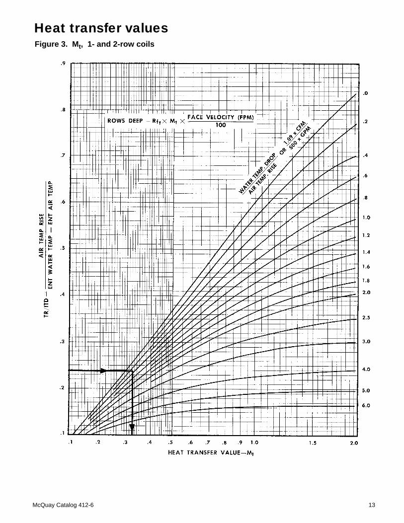
Heat transfer valuesFigure 3. Mt, 1- and 2-row coils
McQuay Catalog 412-6 13
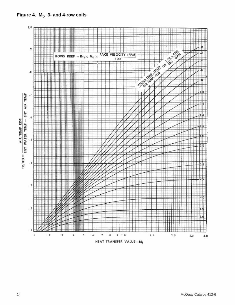
Figure 4. Mt, 3- and 4-row coils
14 McQuay Catalog 412-6
.2 .4 .6 .8 1.0 1.2
.1 .2 .3 .4 .5 .65BB & 5NB
ALL OTHERS
Rf1
.2
.3
.4
.5
.6
.7
.8
.9
1.0
1.5
2.0
3.0
4.0
5.0
6.0
7.0
8.0
GPM
/ Fe
ed
AVERAGE WATER
TEMPERATURE, °F100
130
180
230
300
HI-F5 selection dataFigure 5. Heat transfer values - Rf, HI-F5 coils
NOTE: Heat transfer values for odd fin spacings may be found byinterpolation.
300
.8
15001000500 800
Rf2 - 1 & 2 Row - Type 5BB & 5WB
.7
.6
.5
.4
.3
.2
Face Velocity - FPM
Rf2
FIN SERIES 10FIN SERIES 12FIN SERIES 14
400 600
- All Other Types.8
.7
.6
.5
.4
.3
.2
300 15001000500 800
Face Velocity - FPM
Rf2
FIN SERIES 06
FIN SERIES 08FIN SERIES 10FIN SERIES 12
FIN SERIES 14
Rf2
5 BB & 5WB
ALL OTHERS
McQuay Catalog 412-6 15
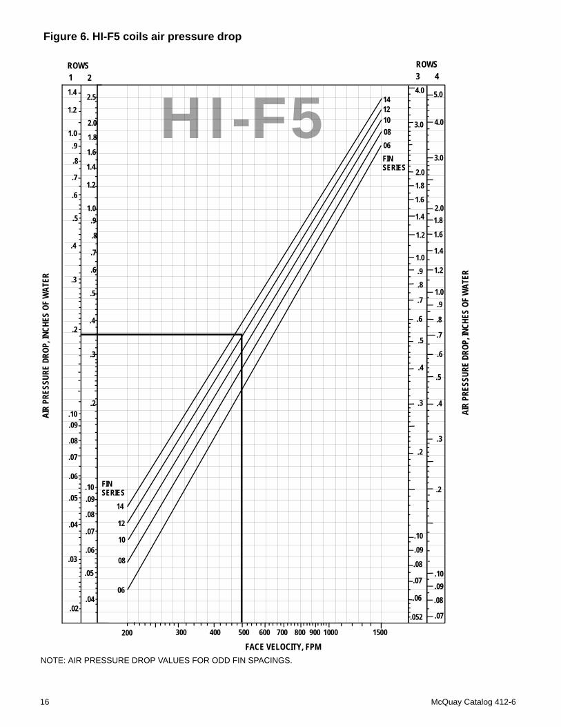
Figure 6. HI-F5 coils air pressure drop
NOTE: AIR PRESSURE DROP VALUES FOR ODD FIN SPACINGS.
HI-F5ROWS
2ROWS3 4
AIR
PRES
SURE
DRO
P, IN
CHES
OF
WAT
ER
AIR
PRES
SURE
DRO
P, IN
CHES
OF
WAT
ER
FACE VELOCITY, FPM200 300 400 500 600 700 800 900 1000 1500
.052
.06
.07
.08
.09
.10
.2
.3
.4
.5
.6
.7
.8
.91.0
1.2
1.4
1.6
1.82.0
3.0
4.0
.2
.3
.4
.5
.6
.7
.8
.91.0
1.4
1.6
1.82.0
3.0
4.0
5.0
1.2
.07
.08
.09
.10
.2
1.4
1.6
1.8
2.0
1.2
.04
.06
.07
.08
.09.10
.05
.3
.4
.5
2.5
1.0
.6
.7
.8
.9
1
14
12
10
08
06
FIN SERIES
1412100806FIN SERIES
1.4
1.2
.3
.4
.5
1.0
.6
.7
.8
.9
.2
.04
.06
.07
.08
.09
.10
.05
.03
.02
16 McQuay Catalog 412-6
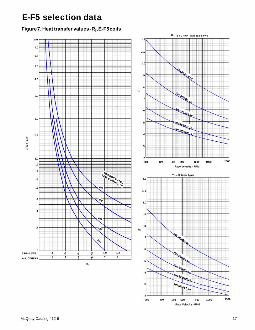
Figure 7. Heat transfer values - Rf, E-F5 coils
.2 .4 .6 .8 1.0 1.2
.1 .2 .3 .4 .5 .65BB & 5NB
ALL OTHERS
Rf1
.2
.3
.4
.5
.6
.7
.8
.9
1.0
1.5
2.0
3.0
4.0
5.0
6.0
7.0
8.0
GPM
/ Fe
ed
AVERAGE WATER
TEMPERATURE, °F100
130
180
230
300
E-F5 selection data
5 BB & 5WB
ALL OTHERS
300
.8
15001000500 800
Rf 2 - 1 & 2 Row - Type 5BB & 5WB
.7
.6
.5
.4
.3
.2
Face Velocity - FPM
1.0
.9
1.1
1.2
Rf2
600400
FIN SERIES 06
FIN SERIES 08
FIN SERIES 10
FIN SERIES 12FIN SERIES 14
300
.8
15001000500 800
2 - All Other Types
.7
.6
.5
.4
.3
.2
Face Velocity - FPM
1.0
.9
1.1
1.2
Rf2
600400
FIN SERIES 06
FIN SERIES 08FIN SERIES 10FIN SERIES 12FIN SERIES 14
Rf
McQuay Catalog 412-6 17
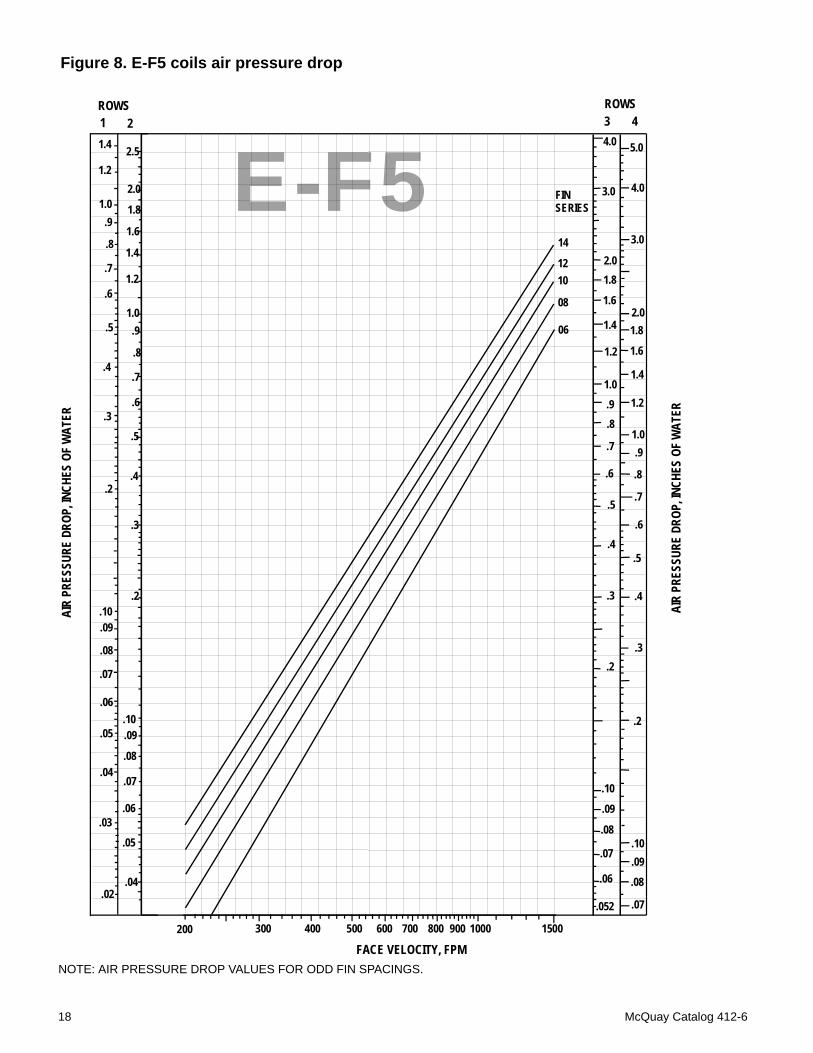
Figure 8. E-F5 coils air pressure drop
NOTE: AIR PRESSURE DROP VALUES FOR ODD FIN SPACINGS.
E-F5ROWS
2ROWS3 4
AIR
PRES
SURE
DRO
P, IN
CHES
OF
WAT
ER
AIR
PRES
SURE
DRO
P, IN
CHES
OF
WAT
ER
FACE VELOCITY, FPM200 300 400 500 600 700 800 900 1000 1500
.052
.06
.07
.08
.09
.10
.2
.3
.4
.5
.6
.7
.8
.91.0
1.2
1.4
1.6
1.82.0
3.0
4.0
.2
.3
.4
.5
.6
.7
.8
.91.0
1.4
1.6
1.82.0
3.0
4.0
5.0
1.2
.07
.08
.09
.10
.2
1.4
1.6
1.8
2.0
1.2
.04
.06
.07
.08
.09.10
.05
.3
.4
.5
2.5
1.0
.6
.7
.8
.9
1
14
1210
08
06
FIN SERIES
1.4
1.2
.3
.4
.5
1.0
.6
.7
.8
.9
.2
.04
.06
.07
.08
.09
.10
.05
.03
.02
18 McQuay Catalog 412-6
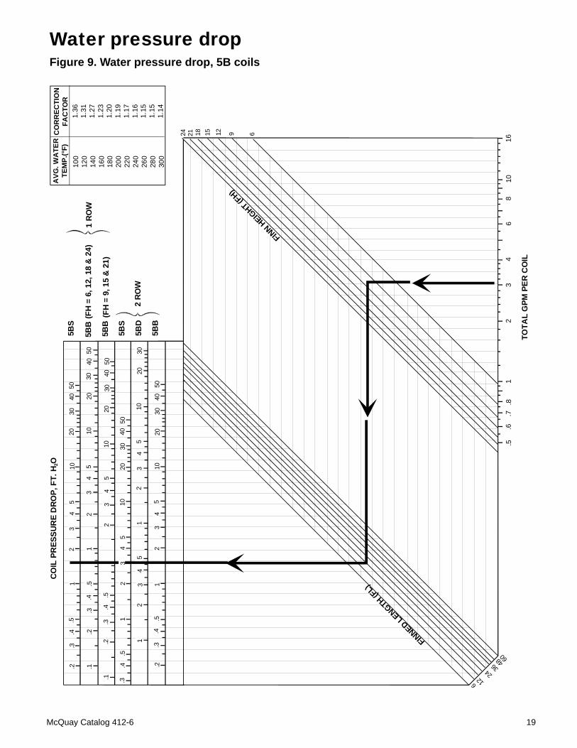
Figure 9. Water pressure drop, 5B coils
Water pressure drop
.5.6
.7.8
12
34
68
1016
.2.3
.4.5
.1.2
.3.4
.5
.1.2
.3.4
.5
.3.4
.5
.2.3
.4.5
12
34
5
12
12
34
5
34
12
3
5
23
45
1
12
2
3
3
4
4
5
51020
3040
50
5040
3020
10
1020
3040
50
5040
3020
105
420
30
5040
3020
10
10
5BB
5BB
5BS
5BS
5BD
5BB
2 R
OW
1 R
OW
(FH
= 6
, 12,
18
& 2
4)
(FH
= 9
, 15
& 2
1)
CO
IL P
RES
SUR
E D
RO
P, F
T. H
2O
24 21 18 15 12 9 6
6 1224
3648 60
TOTA
L G
PM P
ER C
OIL
FINNED LENGTH (F
L)
FINN H
EIGHT (F
H)
100
120
140
160
180
200
220
240
260
280
300
1.36
1.31
1.27
1.23
1.20
1.19
1.17
1.16
1.15
1.15
1.14
AVG
. WA
TER
TEM
P.(°
F)C
OR
REC
TIO
NFA
CTO
R
McQuay Catalog 412-6 19
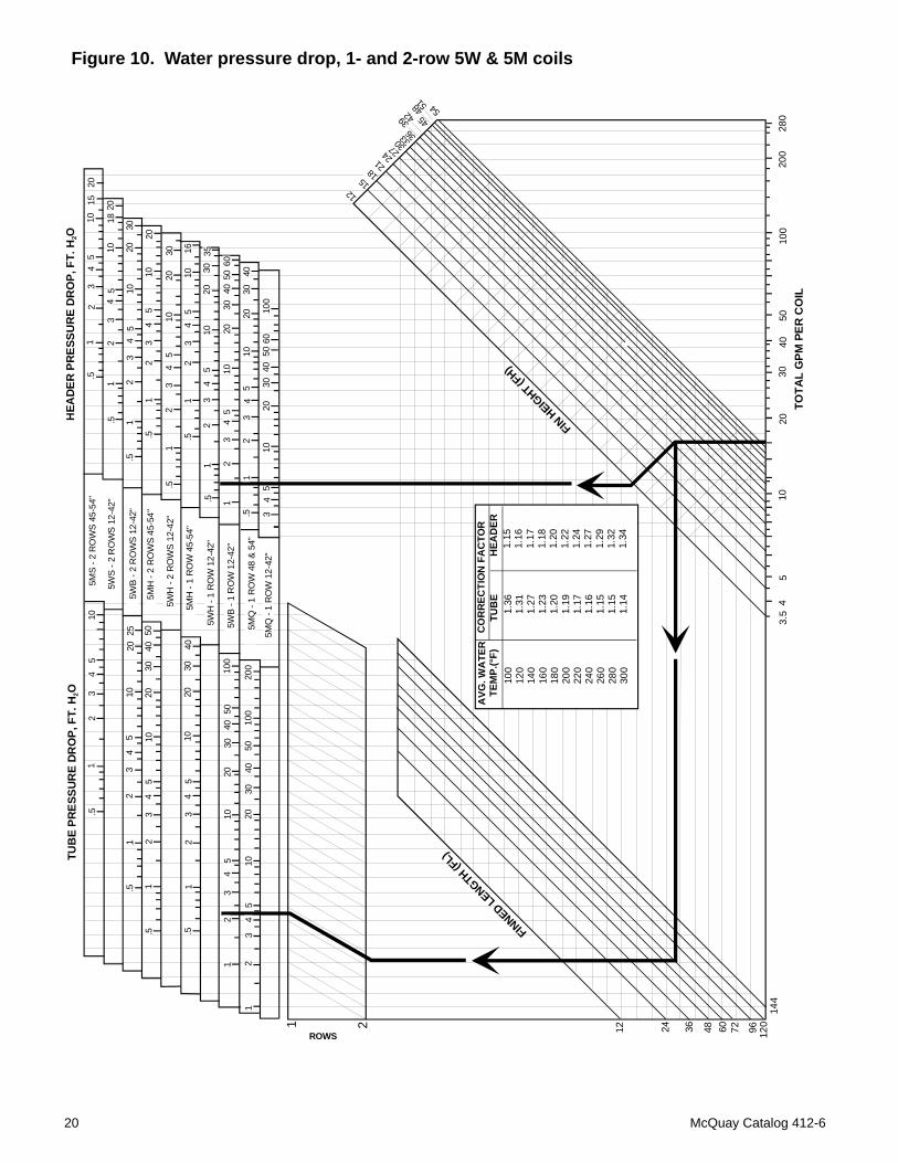
Figure 10. Water pressure drop, 1- and 2-row 5W & 5M coils
5
FINNED LE
NGTH (F
L)
FIN H
EIGHT (F
H)
TOTA
L G
PM P
ER C
OIL
TUB
E PR
ESSU
RE
DR
OP,
FT.
H2O
HEA
DER
PR
ESSU
RE
DR
OP,
FT.
H2O
.5
.5
.5 .5
1
1
1
1 1
12
34
510
2520
10
1020
3040
50
54
32
1
54
32
4030
2010
54
32
5040
3020
1010
0
100
200
5040
3020
54
32
1 23
45
10
.51
23
45
1015
20
2018
10 2030
54
32
1.5
.51
23
45
10
2010
54
32
1.5
.51
23
45
1020
30 1610
54
32
1.5
.51
1
.51
23
45
1020
3035
2040
5060
30
3040
20
10
10
5
5
4
4
3
3
2
2
34
10
2030
4050
6010
0
5MS
- 2 R
OW
S 4
5-54
"
5WS
- 2 R
OW
S 1
2-42
"
5WH
- 2
RO
WS
12-4
2"
5WB
- 2 R
OW
S 1
2-42
"
5MH
- 2
RO
WS
45-5
4"
5MH
- 1
RO
W 4
5-54
"
5WH
- 1
RO
W 1
2-42
"
5WB
- 1 R
OW
12-
42"
5MQ
- 1
RO
W 1
2-42
"
5MQ
- 48
& 5
4"5M
Q -
1 R
OW
48
& 54
"
ROWS
1 2
3.5
45
1020
3040
5010
020
028
0
12 24 36 48 60 72 96 120
144
1215
2124 27
30 33 3639 42 45
48 5154
100
120
140
160
180
200
220
240
260
280
300
1.36
1.31
1.27
1.23
1.20
1.19
1.17
1.16
1.15
1.15
1.14
AVG
. WA
TER
TEM
P.(°
F)C
OR
REC
TIO
N F
AC
TOR
TUB
EH
EAD
ER1.
15
1.16
1.17
1.18
1.20
1.22
1.24
1.27
1.29
1.32
1.34
18
20 McQuay Catalog 412-6
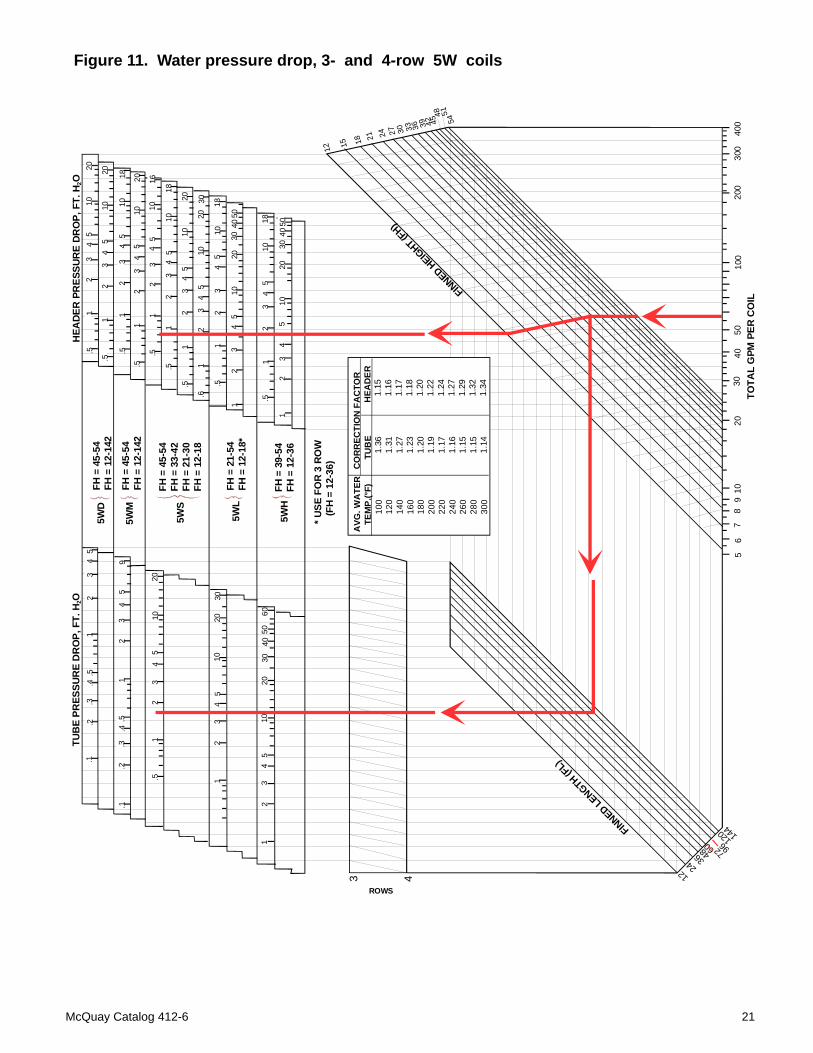
Figure 11. Water pressure drop, 3- and 4-row 5W coilsTU
BE
PRES
SUR
E D
RO
P, F
T. H
2OH
EADE
R P
RES
SUR
E DR
OP,
FT.
H2O
.1.2
.3.4
.51
23
45
95
43
21
.4.5
.3.2
.1
.51
23
45
1020
202
34
510
1
23
45
101
2030
4050
60
30
.51
23
45
1020 20
103
45
21
.5
.51
23
45
1018 20
105
34
21
.5
.51
23
54
1016
1810
54
32
1.5
.51
23
45
1020 30
2010
34
52
1.6
.51
23
45
1018
5040
3020
105
43
21
.51
23
45
1018 50
4030
2010
54
32
1
ROWS
3 4
100
120
140
160
180
200
220
240
260
280
300
1.36
1.31
1.27
1.23
1.20
1.19
1.17
1.16
1.15
1.15
1.14
AVG
. WA
TER
TEM
P.(°
F)C
OR
REC
TIO
N F
AC
TOR
TUB
EH
EAD
ER
1.15
1.
161.
171.
181.
201.
221.
241.
271.
291.
321.
34
12 15
21 24 27 30 33 36 39 42 4548 51
54
18
FINNED LENGTH (F
L)
FINNED HEIGHT (F
H)
1224
36 48 60 72 9612
0 144
56
78
910
2030
4050
100
200
300
400
TOTA
L G
PM P
ER C
OIL
5WS
5WL
5WH
FH =
39-
54FH
= 1
2-36
FH =
21-
54FH
= 1
2-18
*
FH =
45-
54FH
= 3
3-42
FH =
21-
30FH
= 1
2-18
FH =
45-
54FH
= 1
2-14
2
FH =
45-
54FH
= 1
2-14
2
* USE
FO
R 3
RO
W
(FH
= 1
2-36
)
5WD
5WM
McQuay Catalog 412-6 21
E
W
1.50
1.50
SUPPLY
RETURN 0.75
AIRFLOW RH
FINNED LENGTH (FL)
(FROM CL OF FL) 0.75
.375 DIA. @ 6.00 CC
A MAX A MAX
0.375 DIA. HOLESIN CORNERS
TYPICAL ALL FLANGES
1.50
1.50
1.50
3.002.50
2.50
5.00
B
VENT
E
W
1.50
1.50
SUPPLY
RETURN 0.75
AIRFLOW RH
FINNED LENGTH (FL)
(FROM CL OF FL) 0.75
.375 DIA. @ 6.00 CC
A MAX A MAX
0.375 DIA. HOLESIN CORNERS
TYPICAL ALL FLANGES
1.50
1.50
1.50
3.002.50
2.50
5.00
B
VENT
2-1/2
5
CONN.END
OPP.CONN.
END
2-1/2
5
CONN.END
OPP.CONN.
END
SPLIT HEADER ONONE-ROW COILS ONLY.SLUG DIVIDING HEADERON TWO-ROW COILSEXCEPT 5WB TWO-ROW.
SPLIT HEADER(S) ONONE-ROW COILS ONLY.SLUG(S) DIVIDING HEADERON TWO-ROW COILS.
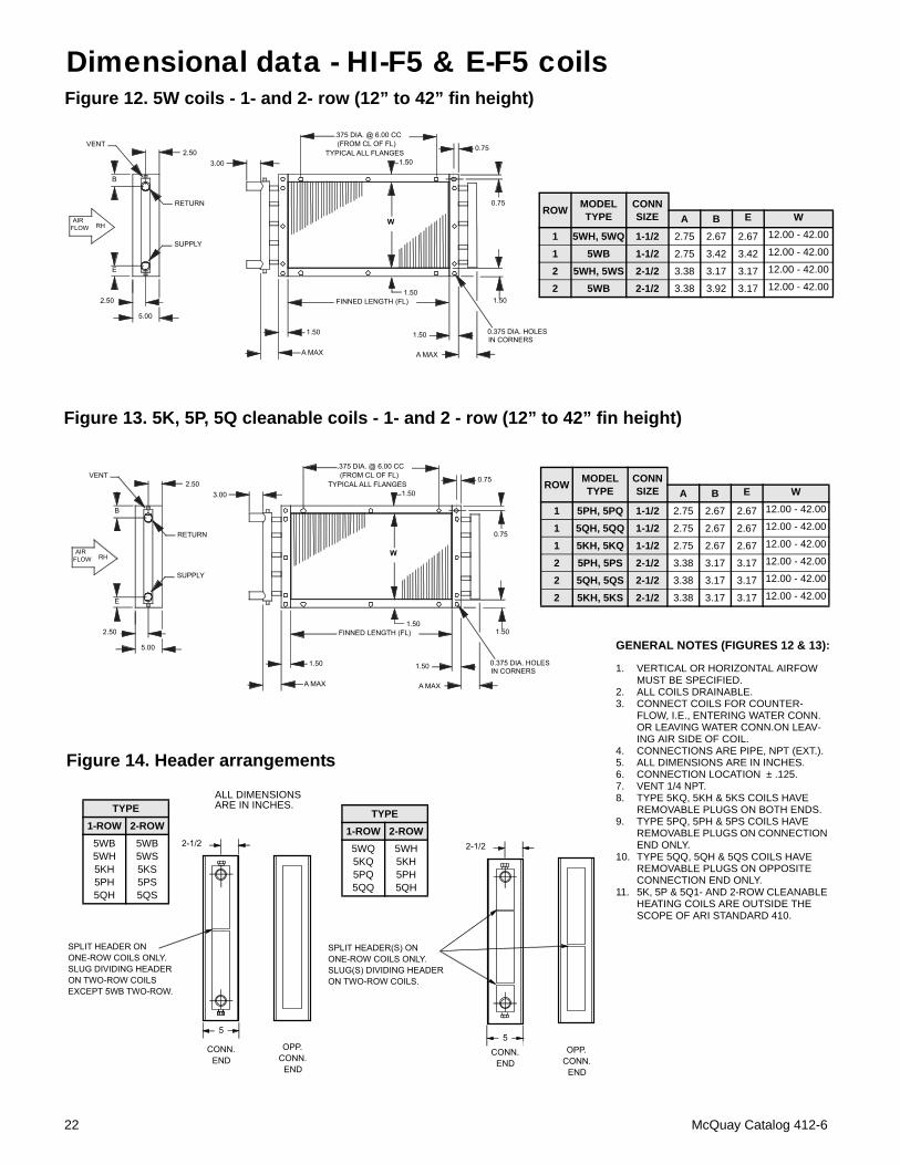
Figure 12. 5W coils - 1- and 2- row (12” to 42” fin height)
Figure 13. 5K, 5P, 5Q cleanable coils - 1- and 2 - row (12” to 42” fin height)
Figure 14. Header arrangements
ROW MODEL TYPE
CONN SIZE A B E W
1 5PH, 5PQ 1-1/2 2.75 2.67 2.67 12.00 - 42.00
1 5QH, 5QQ 1-1/2 2.75 2.67 2.67 12.00 - 42.00
1 5KH, 5KQ 1-1/2 2.75 2.67 2.67 12.00 - 42.00
2 5PH, 5PS 2-1/2 3.38 3.17 3.17 12.00 - 42.00
2 5QH, 5QS 2-1/2 3.38 3.17 3.17 12.00 - 42.00
2 5KH, 5KS 2-1/2 3.38 3.17 3.17 12.00 - 42.00
GENERAL NOTES (FIGURES 12 & 13):
1. VERTICAL OR HORIZONTAL AIRFOW MUST BE SPECIFIED.
2. ALL COILS DRAINABLE.3. CONNECT COILS FOR COUNTER-
FLOW, I.E., ENTERING WATER CONN. OR LEAVING WATER CONN.ON LEAV-ING AIR SIDE OF COIL.
4. CONNECTIONS ARE PIPE, NPT (EXT.).5. ALL DIMENSIONS ARE IN INCHES.6. CONNECTION LOCATION ± .125.7. VENT 1/4 NPT.8. TYPE 5KQ, 5KH & 5KS COILS HAVE
REMOVABLE PLUGS ON BOTH ENDS.9. TYPE 5PQ, 5PH & 5PS COILS HAVE
REMOVABLE PLUGS ON CONNECTION END ONLY.
10. TYPE 5QQ, 5QH & 5QS COILS HAVE REMOVABLE PLUGS ON OPPOSITE CONNECTION END ONLY.
11. 5K, 5P & 5Q1- AND 2-ROW CLEANABLE HEATING COILS ARE OUTSIDE THE SCOPE OF ARI STANDARD 410.
ROW MODEL TYPE
CONN SIZE A B E W
1 5WH, 5WQ 1-1/2 2.75 2.67 2.67 12.00 - 42.00
1 5WB 1-1/2 2.75 3.42 3.42 12.00 - 42.00
2 5WH, 5WS 2-1/2 3.38 3.17 3.17 12.00 - 42.00
2 5WB 2-1/2 3.38 3.92 3.17 12.00 - 42.00
Dimensional data - HI-F5 & E-F5 coils
ALL DIMENSIONS ARE IN INCHES.
TYPE1-ROW 2-ROW5WQ5KQ5PQ5QQ
5WH5KH5PH5QH
TYPE1-ROW 2-ROW
5WB5WH5KH5PH5QH
5WB5WS5KS5PS5QS
22 McQuay Catalog 412-6
.375 DIA. @ 6.00 CC(FROM CL OF FL)
TYPICAL ALL FLANGES
0.75
W + 3.00
1.50
1.501.50
A MAX 1.25 MAX OVERRETURN BENDS
W
FINNED LENGTH (FL)
LHAIR FLOW
AIR FLOW RH
DEPTHDEPTH
H
M
L
G
B
L
E
LEFT HAND AIR FLOW COIL RIGHT HAND
AIR FLOW COIL
DRAIN
SUPPLYSUPPLY
DRAIN
RETURN
RETURN
VENTVENT
.375 DIA. HOLESIN CORNERS
RETURNA MAX
0.75
R. H. RETURN
3.00EXT. TYP.
M
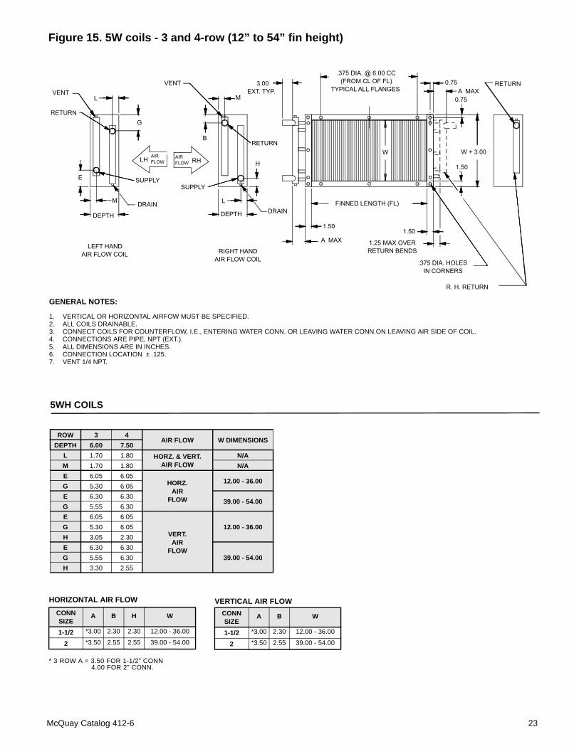
Figure 15. 5W coils - 3 and 4-row (12” to 54” fin height)
GENERAL NOTES:
1. VERTICAL OR HORIZONTAL AIRFOW MUST BE SPECIFIED.2. ALL COILS DRAINABLE.3. CONNECT COILS FOR COUNTERFLOW, I.E., ENTERING WATER CONN. OR LEAVING WATER CONN.ON LEAVING AIR SIDE OF COIL.4. CONNECTIONS ARE PIPE, NPT (EXT.).5. ALL DIMENSIONS ARE IN INCHES.6. CONNECTION LOCATION ± .125.7. VENT 1/4 NPT.
ROW 3 4AIR FLOW W DIMENSIONS
DEPTH 6.00 7.50L 1.70 1.80 HORZ. & VERT.
AIR FLOWN/A
M 1.70 1.80 N/AE 6.05 6.05
HORZ. AIR
FLOW
12.00 - 36.00G 5.30 6.05E 6.30 6.30
39.00 - 54.00G 5.55 6.30E 6.05 6.05
VERT. AIR
FLOW
12.00 - 36.00G 5.30 6.05H 3.05 2.30E 6.30 6.30
39.00 - 54.00G 5.55 6.30H 3.30 2.55
5WH COILS
HORIZONTAL AIR FLOW
* 3 ROW A = 3.50 FOR 1-1/2” CONN4.00 FOR 2” CONN.
CONN SIZE
A B H W
1-1/2 *3.00 2.30 2.30 12.00 - 36.00
2 *3.50 2.55 2.55 39.00 - 54.00
VERTICAL AIR FLOWCONN SIZE
A B W
1-1/2 *3.00 2.30 12.00 - 36.00
2 *3.50 2.55 39.00 - 54.00
McQuay Catalog 412-6 23
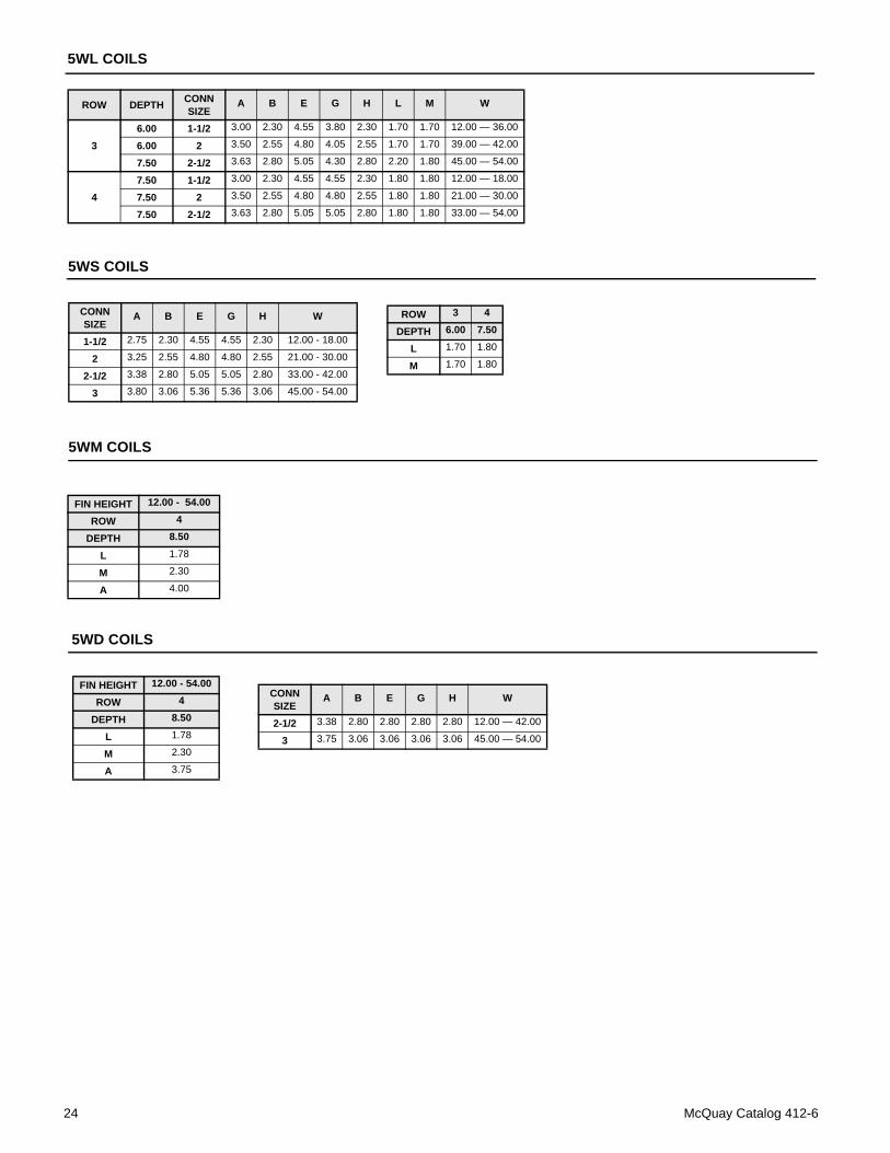
5WM COILS
FIN HEIGHT 12.00 - 54.00
ROW 4
DEPTH 8.50
L 1.78
M 2.30
A 4.00
5WD COILS
CONN SIZE
A B E G H W
2-1/2 3.38 2.80 2.80 2.80 2.80 12.00 — 42.00
3 3.75 3.06 3.06 3.06 3.06 45.00 — 54.00
FIN HEIGHT 12.00 - 54.00
ROW 4
DEPTH 8.50
L 1.78
M 2.30
A 3.75
5WS COILS
CONN SIZE
A B E G H W
1-1/2 2.75 2.30 4.55 4.55 2.30 12.00 - 18.00
2 3.25 2.55 4.80 4.80 2.55 21.00 - 30.00
2-1/2 3.38 2.80 5.05 5.05 2.80 33.00 - 42.00
3 3.80 3.06 5.36 5.36 3.06 45.00 - 54.00
ROW 3 4
DEPTH 6.00 7.50
L 1.70 1.80
M 1.70 1.80
ROW DEPTH CONN SIZE
A B E G H L M W
36.00 1-1/2 3.00 2.30 4.55 3.80 2.30 1.70 1.70 12.00 — 36.00
6.00 2 3.50 2.55 4.80 4.05 2.55 1.70 1.70 39.00 — 42.00
7.50 2-1/2 3.63 2.80 5.05 4.30 2.80 2.20 1.80 45.00 — 54.00
47.50 1-1/2 3.00 2.30 4.55 4.55 2.30 1.80 1.80 12.00 — 18.00
7.50 2 3.50 2.55 4.80 4.80 2.55 1.80 1.80 21.00 — 30.00
7.50 2-1/2 3.63 2.80 5.05 5.05 2.80 1.80 1.80 33.00 — 54.00
5WL COILS
24 McQuay Catalog 412-6
.375 DIA. @ 6.00 CC(FROM CL OF FL)
TYPICAL ALL FLANGES
0.75
W + 3.00
1.50
1.501.50
A MAX .625 MAX OVERRETURN BENDS
W
FINNED LENGTH (FL)
ONE ROW COIL WITH SPLAYED HEADERS
.375 DIA. HOLESIN CORNERS
0.753.00
CD0983632BB-01
LHAIR FLOW
AIR FLOW RH
6.00
H
1.50
B
1.50
RH RETURNLH SUPPLY
1/4 NPTVENT
RH SUPPLYLH RETURN
1/4 NPTDRAIN
DRAIN
VENT
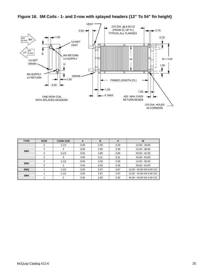
Figure 16. 5M Coils - 1- and 2-row with splayed headers (12” To 54” fin height)
TYPE ROW CONN SIZE A B H W
5MS
2 1-1/2 3.00 2.30 2.30 12.00 - 18.00
2 2 3.50 2.55 2.55 21.00 - 30.00
2 2-1/2 3.63 2.80 2.80 33.00 - 42.00
2 3 4.00 3.11 3.11 45.00 - 54.00
5MH2 1-1/2 3.00 2.30 2.30 12.00 - 36.00
2 2 3.50 2.55 2.55 39.00 - 54.00
5MQ 1 1-1/2 3.00 2.67 2.67 12.00 - 54.00 ON 6.00 C/C
5MH1 1-1/2 3.00 2.67 2.67 12.00 - 42.00 ON 3.00 C/C
1 2 3.50 2.92 2.92 45.00 - 54.00 ON 3.00 C/C
McQuay Catalog 412-6 25
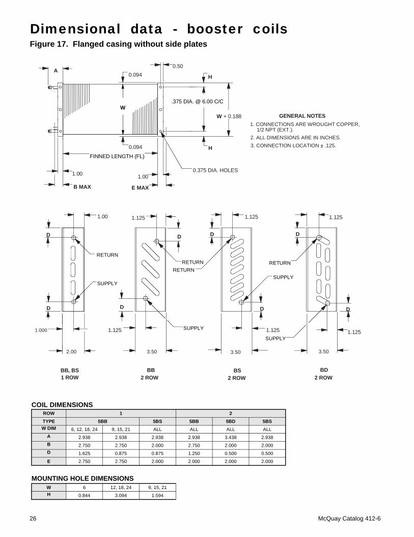
Figure 17. Flanged casing without side plates
COIL DIMENSIONSROW 1 2TYPE 5BB 5BS 5BB 5BD 5BSW DIM 6, 12, 18, 24 9, 15, 21 ALL ALL ALL ALL
A 2.938 2.938 2.938 2.938 3.438 2.938B 2.750 2.750 2.000 2.750 2.000 2.000D 1.625 0.875 0.875 1.250 0.500 0.500
E 2.750 2.750 2.000 2.000 2.000 2.000
MOUNTING HOLE DIMENSIONSW 6 12, 18, 24 9, 15, 21H 0.844 3.094 1.594
Dimensional data - booster coils
RETURN
SUPPLY
D
RETURNRETURN
SUPPLY
RETURN
D
1.125
D
SUPPLY
D
3.50
SUPPLY
3.50
1.125
D
2.00
1.000
D
1.1251.00
1.125 1.125
1.125
3.50
D
D
BB, BS1 ROW
BB2 ROW 2 ROW 2 ROW
BS BD
GENERAL NOTES1. CONNECTIONS ARE WROUGHT COPPER,
2. ALL DIMENSIONS ARE IN INCHES.3. CONNECTION LOCATION ± .125.
1/2 NPT (EXT.).
W.375 DIA. @ 6.00 C/C
HFINNED LENGTH (FL)
1.00
B MAX E MAX
0.375 DIA. HOLES
0.500.094
1.00
W + 0.188
HA
0.094
26 McQuay Catalog 412-6
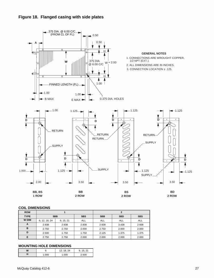
Figure 18. Flanged casing with side plates
COIL DIMENSIONSROW 1 2TYPE 5BB 5BS 5BB 5BD 5BSW DIM 6, 12, 18, 24 9, 15, 21 ALL ALL ALL ALL
A 2.938 2.938 2.938 2.938 3.438 2.938B 2.750 2.750 2.000 2.750 2.000 2.000D 2.500 1.750 1.750 2.125 1.375 1.375
E 2.750 2.750 2.000 2.000 2.000 2.000
MOUNTING HOLE DIMENSIONSW 6 12, 18, 24 9, 15, 21H 1.000 1.000 2.500
RETURN
SUPPLY
(FROM CL OF FL).375 DIA. @ 6.00 C/C
0.50
1.001.00
E MAX
FINNED LENGTH (FL)
W
D
RETURNRETURN
SUPPLY
RETURN
D
1.125
D
SUPPLY
D
3.50
SUPPLY
3.50
1.125
D
0.375 DIA. HOLES
2.00
1.000
D
1.1251.00
1.125 1.125
1.125
3.50
D
D
BB, BS1 ROW
BB2 ROW 2 ROW 2 ROW
BS BD
B MAX
1.00
0.50
W + 2.00
A
GENERAL NOTES1. CONNECTIONS ARE WROUGHT COPPER,
2. ALL DIMENSIONS ARE IN INCHES.3. CONNECTION LOCATION ± .125.
1/2 NPT (EXT.)..375 DIA@ 6.00 C/C
H
H
McQuay Catalog 412-6 27
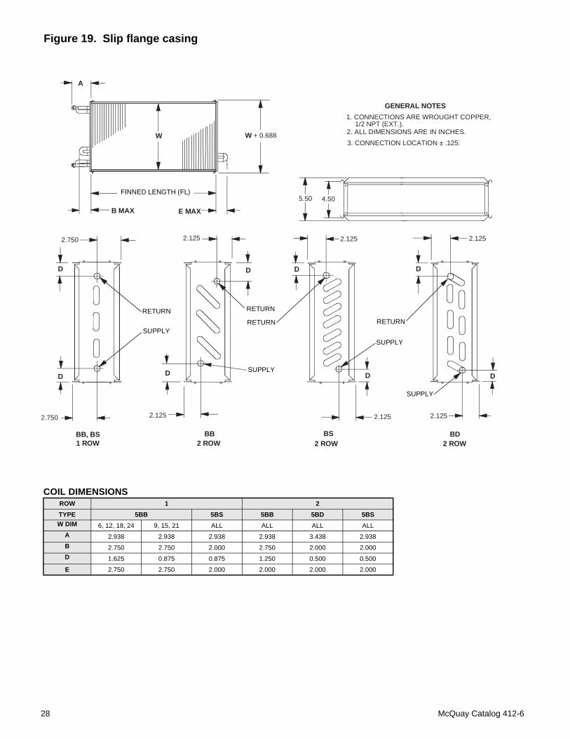
Figure 19. Slip flange casing
COIL DIMENSIONSROW 1 2TYPE 5BB 5BS 5BB 5BD 5BSW DIM 6, 12, 18, 24 9, 15, 21 ALL ALL ALL ALL
A 2.938 2.938 2.938 2.938 3.438 2.938B 2.750 2.750 2.000 2.750 2.000 2.000D 1.625 0.875 0.875 1.250 0.500 0.500
E 2.750 2.750 2.000 2.000 2.000 2.000
W
FINNED LENGTH (FL)
E MAX
RETURN
SUPPLY
RETURN
RETURN
D
D
SUPPLY
D
2.125
SUPPLY
SUPPLY
2.125
D
BS2 ROW
2.125
D
RETURN
2.750
2.1252.750
2.125 2.125
DD
D
BB, BS1 ROW
BB2 ROW 2 ROW
BD
B MAX
W + 0.688
A
GENERAL NOTES1. CONNECTIONS ARE WROUGHT COPPER,
2. ALL DIMENSIONS ARE IN INCHES.3. CONNECTION LOCATION ± .125.
1/2 NPT (EXT.).
5.50 4.50
28 McQuay Catalog 412-6
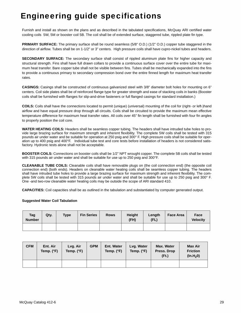
Engineering guide specificationsFurnish and install as shown on the plans and as described in the tabulated specifications, McQuay ARI certified watercooling coils 5W, 5M or booster coil 5B. The coil shall be of extended surface, staggered tube, rippled plate fin type.
PRIMARY SURFACE: The primary surface shall be round seamless (5/8” O.D.) (1/2” O.D.) copper tube staggered in thedirection of airflow. Tubes shall be on 1-1/2” or 3” centers. High pressure coils shall have cupro-nickel tubes and headers.
SECONDARY SURFACE: The secondary surface shall consist of rippled aluminum plate fins for higher capacity andstructural strength. Fins shall have full drawn collars to provide a continuous surface cover over the entire tube for maxi-mum heat transfer. Bare copper tube shall not be visible between fins. Tubes shall be mechanically expanded into the finsto provide a continuous primary to secondary compression bond over the entire finned length for maximum heat transferrates.
CASINGS: Casings shall be constructed of continuous galvanized steel with 3/8” diameter bolt holes for mounting on 6”centers. Coil side plates shall be of reinforced flange type for greater strength and ease of stacking coils in banks (Boostercoils shall be furnished with flanges for slip-and-drive fasteners or full flanged casings for standard installation.)
COILS: Coils shall have the connections located to permit (unique) (universal) mounting of the coil for (right- or left-)handairflow and have equal pressure drop through all circuits. Coils shall be circuited to provide the maximum mean effectivetemperature difference for maximum heat transfer rates. All coils over 45” fin length shall be furnished with four fin anglesto properly position the coil core.
WATER HEATING COILS: Headers shall be seamless copper tubing. The headers shall have intruded tube holes to pro-vide large brazing surface for maximum strength and inherent flexibility. The complete 5W coils shall be tested with 315pounds air under water and be suitable for operation at 250 psig and 300° F. High pressure coils shall be suitable for oper-ation up to 400 psig and 400°F. Individual tube test and core tests before installation of headers is not considered satis-factory. Hydronic tests alone shall not be acceptable.
BOOSTER COILS: Connections on booster coils shall be 1/2” NPT wrought copper. The complete 5B coils shall be testedwith 315 pounds air under water and shall be suitable for use up to 250 psig and 300°F.
CLEANABLE TUBE COILS: Cleanable coils shall have removable plugs on (the coil connection end) (the opposite coilconnection end) (both ends). Headers on cleanable water heating coils shall be seamless copper tubing. The headersshall have intruded tube holes to provide a large brazing surface for maximum strength and inherent flexibility. The com-plete 5W coils shall be tested with 315 pounds air under water and shall be suitable for use up to 250 psig and 300° F.One -and two-row cleanable water heating coils may be outside the scope of ARI standard 410.
CAPACITIES: Coil capacities shall be as outlined in the tabulation and substantiated by computer generated output.
Suggested Water Coil Tabulation
Tag Number
Qty. Type Fin Series Rows Height (FH)
Length (FL)
Face Area Face Velocity
CFM Ent. Air Temp. (°F)
Lvg. Air Temp. (°F)
GPM Ent. Water Temp. (°F)
Lvg. Water Temp. (°F)
Max. Water Press. Drop
(Ft.)
Max Air Friction (In.H20)
McQuay Catalog 412-6 29

Notes
30 McQuay Catalog 412-6


© 2006 McQuay International • www.mcquay.com • 800-432-1342 Catalog 412-6 (06/06)
McQuay Training and Development
Now that you have made an investment in modern, efficient McQuay equipment, its care should be a high priority. For training information on all McQuay HVAC products, please visit us at www.mcquay.com and click on training, or call 540-248-9646 and ask for the Training Department.
WarrantyAll McQuay equipment is sold pursuant to its standard terms and conditions of sale, including Limited Product Warranty. Consult your local McQuay Representative for warranty details. Refer to Form 933-43285Y. To find your local McQuay Representative, go to www.mcquay.com.
This document contains the most current product information as of this printing. For the most up-to-date product information, please go to www.mcquay.com.