Embed Size (px)
Citation preview

MCS Series • Microprocessor based soft-start / soft-stop controller • Ratings from 25A to 90A @ 48-530 VAC • Low-voltage, current, or potentiometer control • Output status indicator • Adjustable ramp rates
PRODUCT SELECTION
Line Voltage 25 A 50 A 90 A120 Vrms MCST1225 MCST1250 MCST1290240 Vrms MCST2425 MCST2450 MCST2490480 Vrms MCST4825 MCST4850 MCST4890
AVAILABLE OPTIONS
OUTPUT SPECIFICATIONS (voltage)
Description 120 VAC 240 VAC 480 VACOperating Voltage (47-63Hz) [Vrms] 48-140 180-280 300-530Transient Overvoltage [Vpk] 400 600 1200Maximum Off-State Leakage Current @ Rated Voltage [mArms] 5 7 12Minimum Off-State dv/dt @ Maximum Rated Voltage [V/µsec] 200 200 200
OUTPUT SPECIFICATIONS (current)
Description 25 A 50 A 90 AMaximum Load Current [Arms] 25 50 90Minimum Load Current [mArms] 150 150 150Maximum Surge Current (16.6ms) [Apk] 250 625 1200Maximum On-State Voltage Drop @ Rated Current [Vpk] 1.6 1.6 1.6Thermal Resistance Junction to Case (Rjc) [°C/W] 1.02 0.63 0.28Maximum I²t for Fusing (8.3 msec) [A²sec] 260 1620 6000

INPUT SPECIFICATIONS (1)
Description DC ControlControl Voltage Range (VDC) 8-32Input Current Range [mA] [P1] 28-30Nominal Input Impedance [Ohms] [P3] 30KControl Must Operate Voltage "On"[VDC][P3] 5-32Control Must Release Voltage "Off" [VDC][P3] 0-4Input Current [mA][P3] 0-2.6Analog Range Option A [VDC][P4] 0.5-5Analog Range Option B [VDC][P4] 1.25-7Analog Range Option C [VDC][P4] 2-10Analog Range Option D [VDC][P4] 4-20Nominal Input Impedance Option A,B,C[ohms][P4] 20KNominal Input Impedance Option D [ohms][P4] 220
GENERAL SPECIFICATIONS
Description ParametersMinimum Power Factor (with Maximum Load) 0.5Dielectric Strength, Input/Output/Base (50/60Hz) 4000 VrmsMinimum Insulation Resistance (@ 500 V DC) 109 OhmMaximum Capacitance, Input/Output 10 pFAmbient Operating Temperature Range -20 to 80°CAmbient Storage Temperature Range -40 to 125 °CWeight (typical) 3.0 oz (86.5g)Encapsulation Thermally conductive EpoxyTerminals-Power Screws and Saddle Clamps Furnished, UnmountedTerminals-Control Barrier Strip Screw TerminalsRecommended Terminal Screw Torque Range: 8-32 Screws -20 in. lbs.(Screws dry without grase)
Input Connections via Screw Type Barrier Strip
GENERAL NOTES1) Voltages are reference to GND (Ground = 0 VDC) P2
OUTPUT STATUS FUNCTIONS
Conditions LED StatusInitial Logic Supply On Flash OnceLoad Voltage Missing / Load Open (w/control P3 disabled) Flash Once IntermittenlyLoad Voltage Missing / Load Open (w/control P3 enabled)) OffRamp Time (Soft Start upon P3 Enabled) Off to BrightRamp Time (Soft Start upon P3 Disabled) Bright to OffOutput ON (Normally Steady Operation) On
THERMAL DERATE INFORMATION

MECHANICAL SPECIFICATIONS
RAMP TIME IN SECONDS
AGENCY APPROVALSUL E116949
Rev. 082710

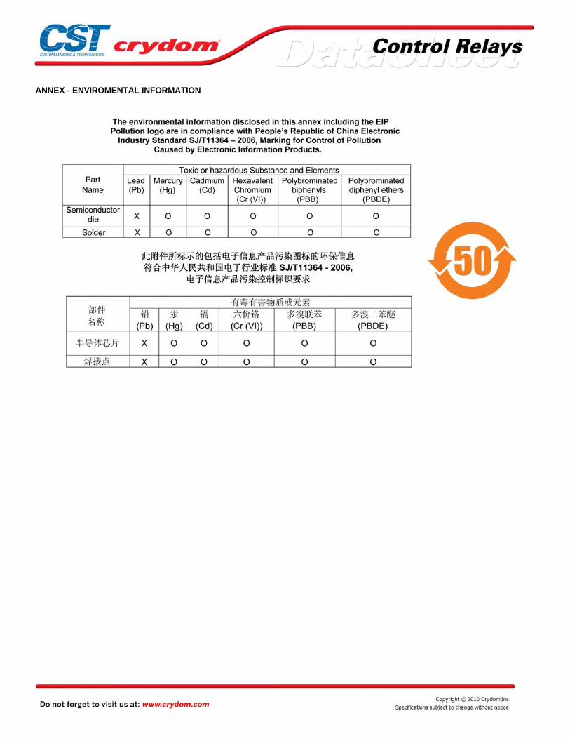
ANNEX - ENVIROMENTAL INFORMATION