Embed Size (px)
Citation preview
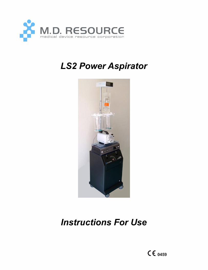
LS2 Power Aspirator
Instructions For Use
Effective 09-Apr-2012 Version 3.0
Table of Contents
Introduction ............................................................................................................................................. 2
Disclaimer ................................................................................................................................................. 2
Unpacking and Inspection ...................................................................................................................... 3
Understanding Your Aspirator ............................................................................................................... 3
Technical Specifications ........................................................................................................................ 3
System Components ............................................................................................................................... 6
Important Features ................................................................................................................................ 9
Warnings and Cautions ........................................................................................................................... 9
Initial Set-Up .......................................................................................................................................... 12
Recommendations .................................................................................................................................. 14
Operating the Aspirator ........................................................................................................................ 14
Periodic Maintenance Schedule ........................................................................................................... 15
User Servicing ........................................................................................................................................ 15
Warranty Provisions .............................................................................................................................. 17
Troubleshooting ..................................................................................................................................... 18
Requesting Service ................................................................................................................................. 22
Contact Information .............................................................................................................................. 22
Immunity test ......................................................................................................................................... 24
2
IntroductionThank you for purchasing the LS2 Power Aspirator. This unit has been engineered and manufactured by M.D. Resource to provide many years of trouble-free use.
Please read this document thoroughly before setting up and operating your new power aspirator.
DisclaimerM.D. Resource has exercised reasonable care in the manufacture of this device. M.D. Resource excludes all warranties, whether express or implied by operation of law or otherwise, including, but not limited to, any implied warranties of MERCHANTABILITY or FITNESS, since handling, storage, and cleaning of this device as well as factors relating to the patient, his diagnosis, treatment, surgical procedures, and other matters beyond M.D. Resource’s control directly affect this device and the results obtained from its use. M.D. Resource shall not be liable for any INCIDENTAL OR CONSEQUENTIAL LOSS, DAMAGE, and OR EXPENSE directly or indirectly arising from the use of this device. M.D. Resource neither assumes, nor authorizes any other person to assume for it, any other or ADDITIONAL LIABILITY OR RESPONSIBILITY in connection with this device.
Caution: Federal law (U.S.A.) restricts this device to sale by or on the order of a physician.
Because of continuing product improvements, prices, specifications, and model availability are subject to change without notice.
Unpacking and InspectionCarefully unpack the large box of all of its contents before trying to remove the LS. Most often, all of the components and everything to do the first procedure is included the same box, including tubing, canisters, filter.
Due to the LS2’s weight, it may be best to minimize the amount of lifting involved by cutting the cardboard box open so the unit can be rolled out.
Each system is carefully packed before shipment. If any part of the system appears to have been damaged during shipment, please contact Customer Service for further guidance.
Understanding Your Aspirator
Technical SpecificationsPlease note that the following technical specifications are subject to change without notice.
Display: 20-segment, 3-color LED bar graph; two-digit LED numeric vacuum readout.
Motors: 2 maintenance-free, non-polluting, oilless rotary vane pumps; serial staging; 0.25hp each.
Vacuum: Adjustable from 0 to 29in Hg (-76mm Hg) at sea level.
Cooling: 2 high-speed low noise AC fans
Power: 100-120 or 200-240 VAC 50-60 Hz; not user selectable; specified with order.
Power Consumption: 1440 watts (maximum) with pumps at maximum speed
Sound Level: <50dBa.
3
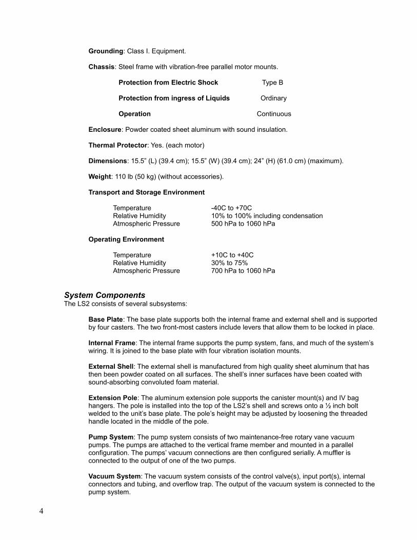
Grounding: Class I. Equipment.
Chassis: Steel frame with vibration-free parallel motor mounts.
Protection from Electric Shock Type B
Protection from ingress of Liquids Ordinary
Operation Continuous Enclosure: Powder coated sheet aluminum with sound insulation.
Thermal Protector: Yes. (each motor)
Dimensions: 15.5” (L) (39.4 cm); 15.5” (W) (39.4 cm); 24” (H) (61.0 cm) (maximum).
Weight: 110 lb (50 kg) (without accessories).
Transport and Storage Environment
Temperature -40C to +70CRelative Humidity 10% to 100% including condensationAtmospheric Pressure 500 hPa to 1060 hPa
Operating Environment
Temperature +10C to +40CRelative Humidity 30% to 75%Atmospheric Pressure 700 hPa to 1060 hPa
System ComponentsThe LS2 consists of several subsystems:
Base Plate: The base plate supports both the internal frame and external shell and is supported by four casters. The two front-most casters include levers that allow them to be locked in place.
Internal Frame: The internal frame supports the pump system, fans, and much of the system’s wiring. It is joined to the base plate with four vibration isolation mounts.
External Shell: The external shell is manufactured from high quality sheet aluminum that has then been powder coated on all surfaces. The shell’s inner surfaces have been coated with sound-absorbing convoluted foam material.
Extension Pole: The aluminum extension pole supports the canister mount(s) and IV bag hangers. The pole is installed into the top of the LS2’s shell and screws onto a ½ inch bolt welded to the unit’s base plate. The pole’s height may be adjusted by loosening the threaded handle located in the middle of the pole.
Pump System: The pump system consists of two maintenance-free rotary vane vacuum pumps. The pumps are attached to the vertical frame member and mounted in a parallel configuration. The pumps’ vacuum connections are then configured serially. A muffler is connected to the output of one of the two pumps.
Vacuum System: The vacuum system consists of the control valve(s), input port(s), internal connectors and tubing, and overflow trap. The output of the vacuum system is connected to the pump system.
4
Cooling System: The cooling system consists of two AC fans that operate continuously when the LS2 is switched on.
Electrical System: The electrical system consists of a terminal block, wiring, power switch, pneumatic switch, transformer, in-line fuse, circuit breaker, and universal power plug.
Electronic Display: The electronic display consists of a single circuit board containing all of the aspirator’s microelectronics. The brightness of the display has been set during production and does not need to be adjusted by the operator.
5
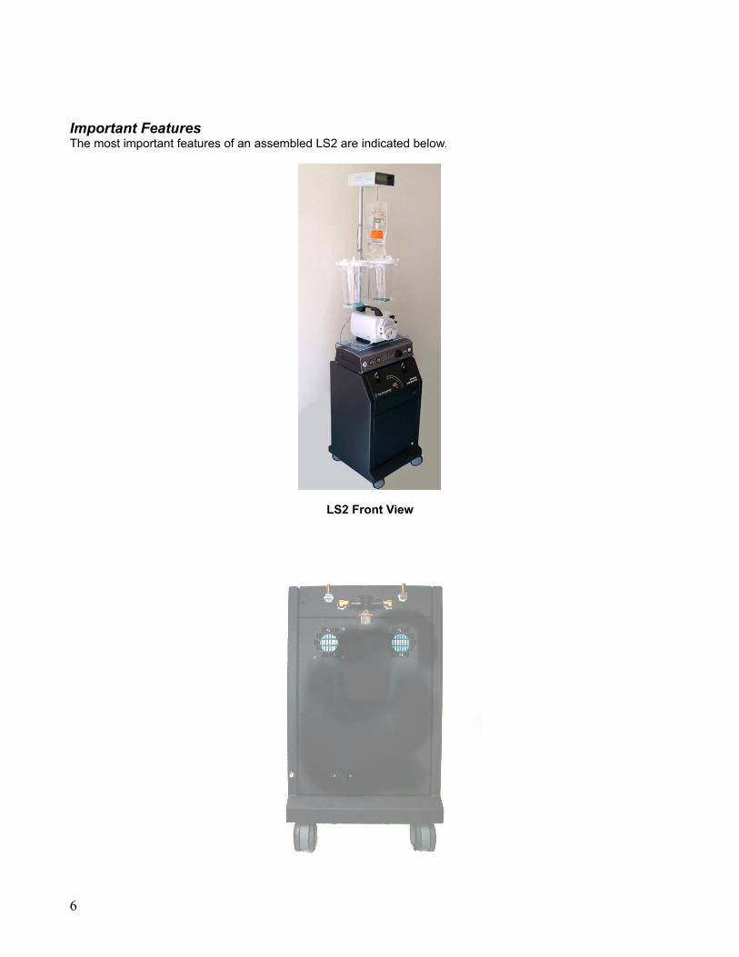
Important FeaturesThe most important features of an assembled LS2 are indicated below.
LS2 Front View
6
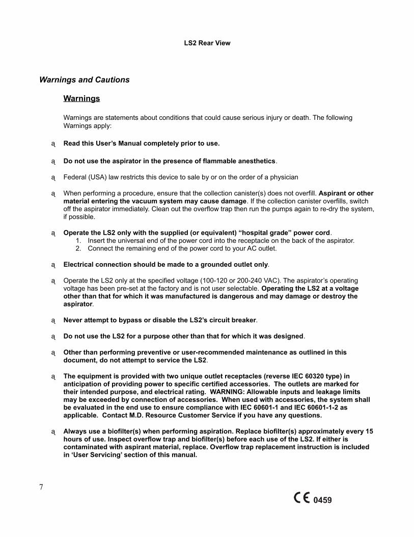
LS2 Rear View
Warnings and Cautions
Warnings
Warnings are statements about conditions that could cause serious injury or death. The following Warnings apply:
Read this User’s Manual completely prior to use.
Do not use the aspirator in the presence of flammable anesthetics.
Federal (USA) law restricts this device to sale by or on the order of a physician
When performing a procedure, ensure that the collection canister(s) does not overfill. Aspirant or other material entering the vacuum system may cause damage. If the collection canister overfills, switch off the aspirator immediately. Clean out the overflow trap then run the pumps again to re-dry the system, if possible.
Operate the LS2 only with the supplied (or equivalent) “hospital grade” power cord.1. Insert the universal end of the power cord into the receptacle on the back of the aspirator.2. Connect the remaining end of the power cord to your AC outlet.
Electrical connection should be made to a grounded outlet only.
Operate the LS2 only at the specified voltage (100-120 or 200-240 VAC). The aspirator’s operating voltage has been pre-set at the factory and is not user selectable. Operating the LS2 at a voltage other than that for which it was manufactured is dangerous and may damage or destroy the aspirator.
Never attempt to bypass or disable the LS2’s circuit breaker.
Do not use the LS2 for a purpose other than that for which it was designed.
Other than performing preventive or user-recommended maintenance as outlined in this document, do not attempt to service the LS2.
The equipment is provided with two unique outlet receptacles (reverse IEC 60320 type) in anticipation of providing power to specific certified accessories. The outlets are marked for their intended purpose, and electrical rating. WARNING: Allowable inputs and leakage limits may be exceeded by connection of accessories. When used with accessories, the system shall be evaluated in the end use to ensure compliance with IEC 60601-1 and IEC 60601-1-2 as applicable. Contact M.D. Resource Customer Service if you have any questions.
Always use a biofilter(s) when performing aspiration. Replace biofilter(s) approximately every 15 hours of use. Inspect overflow trap and biofilter(s) before each use of the LS2. If either is contaminated with aspirant material, replace. Overflow trap replacement instruction is included in ‘User Servicing’ section of this manual.
7
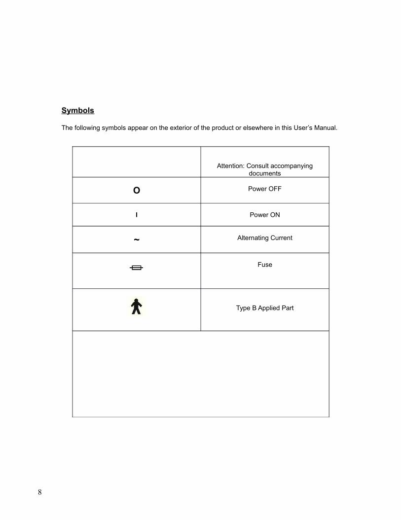
Symbols
The following symbols appear on the exterior of the product or elsewhere in this User’s Manual.
Attention: Consult accompanying documents
O Power OFF
I Power ON
~ Alternating Current
Fuse
Type B Applied Part
8
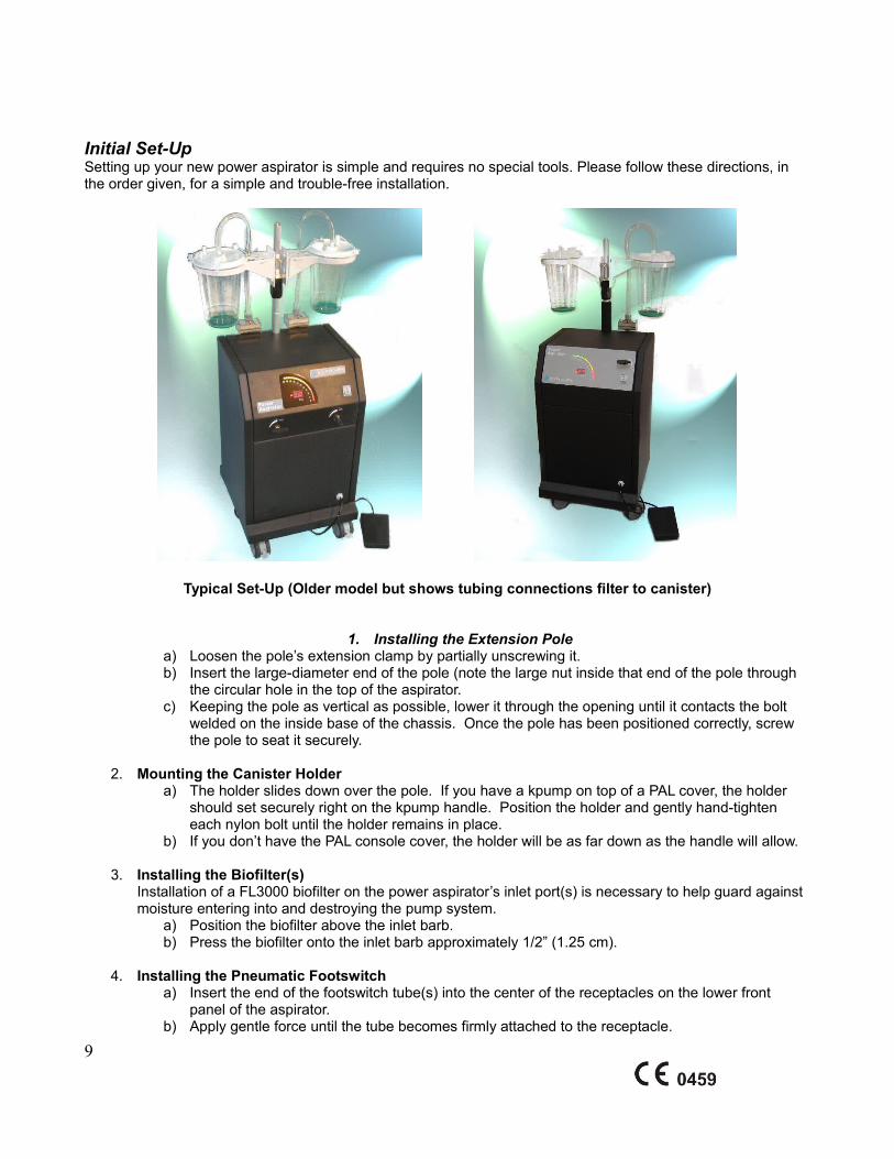
Initial Set-UpSetting up your new power aspirator is simple and requires no special tools. Please follow these directions, in the order given, for a simple and trouble-free installation.
Typical Set-Up (Older model but shows tubing connections filter to canister)
1. Installing the Extension Polea) Loosen the pole’s extension clamp by partially unscrewing it.b) Insert the large-diameter end of the pole (note the large nut inside that end of the pole through
the circular hole in the top of the aspirator.c) Keeping the pole as vertical as possible, lower it through the opening until it contacts the bolt
welded on the inside base of the chassis. Once the pole has been positioned correctly, screw the pole to seat it securely.
2. Mounting the Canister Holdera) The holder slides down over the pole. If you have a kpump on top of a PAL cover, the holder
should set securely right on the kpump handle. Position the holder and gently hand-tighten each nylon bolt until the holder remains in place.
b) If you don’t have the PAL console cover, the holder will be as far down as the handle will allow.
3. Installing the Biofilter(s)Installation of a FL3000 biofilter on the power aspirator’s inlet port(s) is necessary to help guard against moisture entering into and destroying the pump system.
a) Position the biofilter above the inlet barb.b) Press the biofilter onto the inlet barb approximately 1/2” (1.25 cm).
4. Installing the Pneumatic Footswitcha) Insert the end of the footswitch tube(s) into the center of the receptacles on the lower front
panel of the aspirator.b) Apply gentle force until the tube becomes firmly attached to the receptacle.
9
5. Connecting the Power CordYour aspirator uses a “hospital grade” power cord with a universal connector.
a) Insert the universal end of the power cord into the receptacle on the back of the aspirator.b) Connect the remaining end of the power cord to your AC outlet.c) You have an auxiliary outlet for your PAL console and/or infiltration pump.
Recommendations
The biofilter(s) is designed to prevent moisture from entering the pump system. Replace the biofilter(s) after approximately 15 hours of use. Doing so is necessary preventative maintenance.
The overflow trap is located on the back of the LS2 and functions as a filter of “last resort” to help prevent aspirant from entering the pump system. This trap has been designed to allow for easy visual inspection. Inspect the trap regularly to ensure that it is free of obstructions or foreign matter. If it appears to be clogged or darkened, order a replacement and refer to the section titled User Servicing.
We recommend replace or empty the collection canister at no more than 90% full. This helps prevent a sudden surge of aspirant from overflowing the collection canister and causing damage to the aspirator.
Run the aspirator a few minutes without canisters attached at the conclusion of each surgery to help “dry” it out. Using the pneumatic footswitch, activate the pump system and allow it to run at “max” (one knob at a time set to “max” for the Dual Port model) for a period of 3-5 minutes with all accessories detached from the input port(s). This helps air dry the pumps so that moisture does not accumulate in the system.
Operating the AspiratorThe following procedure is suggested for operating your LS2 aspirator:
1. Roll the system into place then lock the lockable casters.2. Connect the aspirator accessories as described above.3. Switch on the aspirator using the front panel power switch (I/O).4. Activate/deactivate the vacuum system as required using the pneumatic footswitch.5. Adjust the amount of suction using the front-panel vacuum control knob(s).
Note: For the DP (Dual Port) model, ensure that both vacuum control knobs are not set to their maximum settings. To generate proper vacuum on an input port, the other control knob should be turned to its minimum setting.
As a safety precaution, it is suggested that the operator deactivate the vacuum system with the pneumatic footswitch before switching off the aspirator. This runs the fans, which cools the pumps after their use.
Periodic Maintenance ScheduleTo help ensure years of trouble-free operation, the LS2 requires simple periodic maintenance.
Before each use: Visually inspect the filter and overflow trap to ensure aspirant has not entered the LS2’s vacuum system and both are clean and dry.
After each surgery: Using the pneumatic footswitch, activate the pump system and allow it to run with the vacuum control knob set to “max” (one knob at a time set to “max” for the Dual Port model) for a period of 3 minutes with all accessories detached from the vacuum input port(s). This will help ensure that moisture does not accumulate in the pump system.
10
For every 15 hours of use: After the aspirator and filter has been used for approximately 15 hours, remove the FL3000 bio-filter on the input port and install a new one. For every 200 hours of use: After the aspirator has been used for approximately 100 hours, unscrew the clear overflow trap bowl and remove the white overflow trap barrier. Install a new overflow trap barrier.
As required: Wipe the outside of the LS2 with a moist rag to remove any dust or foreign matter. Do not use chemicals or abrasives; doing so may destroy the decals and/or the powder coat finish.
User ServicingThe LS2 contains two user-serviceable parts: the overflow trap located on the back of the unit and the FL3000 biofilter need to changed as previously stated.
The function of the overflow trap is to act as a filter of “last resort” to help prevent aspirant from entering the pump system.
If aspirant has overflowed the collection canister and stopped at the disposable biofilter, remove the bio-filter and the connected tubing. Run the system for several minutes to insure it is run clean and dry. Verify that the overflow trap contains no aspirant or moisture. If the system appears to be dry and aspirant-free, the aspirator should function normally once the biofilter and tubing have been replaced.
If aspirant has overflowed the collection canister, passed through the disposable biofilter, and entered the overflow trap:
FIRST, DISCONNECT ALL FILTERS, OVERFLOW TRAP, AND TUBING. RUN SYSTEM CLEAN AND DRY IMMEDIATELY FOR 30 MINUTES TO ATTEMPT TO PURGE AND DRY THE PUMPS. THIS MAY SEEM CONTERINTUITIVE, BUT WE ARE TRYING TO DRY THE PUMPS BEFORE SALINE AND EXUDATE CAN SETTLE IN AND CORRODE THE INSIDES OF THE PUMPS.
1. Remove the biofilter and associated tubing from the input port.2. Unscrew the clear plastic bowl from the overflow trap body. Remove the clear plastic bowl, rubber
washer, and white overflow trap barrier. Discard the overflow trap barrier and order a new one.3. If it appears little or no fat went through the filter, run the pumps for approximately 20 minutes with
no connections and no filters to attempt to dry the internal pumps out and expel any moisture that may have passed through.
4. Rinse and dry the clear plastic bowl and rubber washer until they are clean. Allow them to dry completely.
5. As long as the internal pumps are dry, the system may be okay. 6. If you have a biomed or clinical engineering team who want to advance the cleaning procedure, follow
the steps below. Otherwise, if the system is compromised and an internal pump is damaged, it is recommended to call us to arrange for the system to be picked up and brought in for repair.
7. For the SP (Single input Port) model, turn the vacuum control valve to its maximum setting. For the DP (Dual input Port) model, turn one vacuum control valve to its maximum setting and the other to its minimum setting.
8. High-pressure air can be used to push all moisture out of the valve and hose system while the overflow trap is off. Gauze or other absorbent barrier should be used to collect any residue.
9. For the DP (Dual input Port) model, turn the vacuum control valve now set at “max” to its minimum setting and turn the other valve from the minimum setting to “max”. Repeat steps 10 and 11.
10. Ideally, the system should be completely dry at all times. Reinstall the extension pole and accessories.11. Install a new Biofilter, tubing and overflow filter on the input port(s).
Warranty Provisions
11
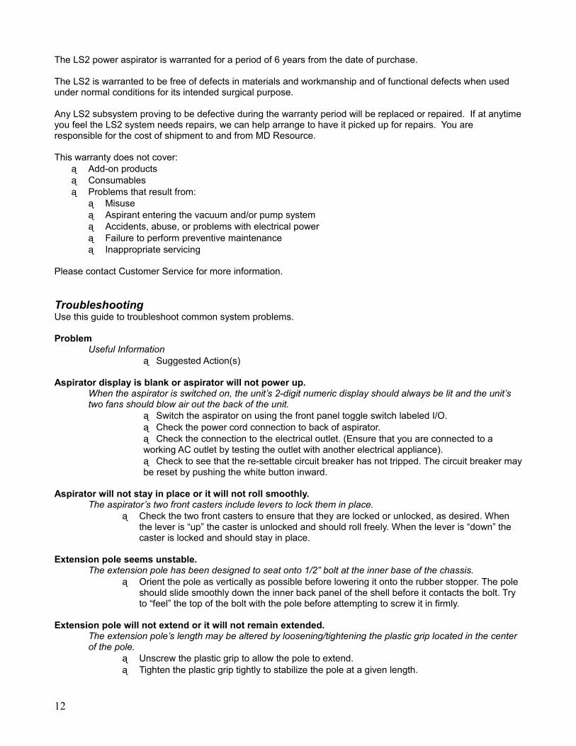
The LS2 power aspirator is warranted for a period of 6 years from the date of purchase.
The LS2 is warranted to be free of defects in materials and workmanship and of functional defects when used under normal conditions for its intended surgical purpose.
Any LS2 subsystem proving to be defective during the warranty period will be replaced or repaired. If at anytime you feel the LS2 system needs repairs, we can help arrange to have it picked up for repairs. You are responsible for the cost of shipment to and from MD Resource.
This warranty does not cover: Add-on products Consumables Problems that result from:
Misuse Aspirant entering the vacuum and/or pump system Accidents, abuse, or problems with electrical power Failure to perform preventive maintenance Inappropriate servicing
Please contact Customer Service for more information.
TroubleshootingUse this guide to troubleshoot common system problems.
ProblemUseful Information
Suggested Action(s)
Aspirator display is blank or aspirator will not power up.When the aspirator is switched on, the unit’s 2-digit numeric display should always be lit and the unit’s two fans should blow air out the back of the unit.
Switch the aspirator on using the front panel toggle switch labeled I/O. Check the power cord connection to back of aspirator. Check the connection to the electrical outlet. (Ensure that you are connected to a working AC outlet by testing the outlet with another electrical appliance). Check to see that the re-settable circuit breaker has not tripped. The circuit breaker may be reset by pushing the white button inward.
Aspirator will not stay in place or it will not roll smoothly.The aspirator’s two front casters include levers to lock them in place.
Check the two front casters to ensure that they are locked or unlocked, as desired. When the lever is “up” the caster is unlocked and should roll freely. When the lever is “down” the caster is locked and should stay in place.
Extension pole seems unstable.The extension pole has been designed to seat onto 1/2” bolt at the inner base of the chassis.
Orient the pole as vertically as possible before lowering it onto the rubber stopper. The pole should slide smoothly down the inner back panel of the shell before it contacts the bolt. Try to “feel” the top of the bolt with the pole before attempting to screw it in firmly.
Extension pole will not extend or it will not remain extended.The extension pole’s length may be altered by loosening/tightening the plastic grip located in the center of the pole.
Unscrew the plastic grip to allow the pole to extend. Tighten the plastic grip tightly to stabilize the pole at a given length.
12
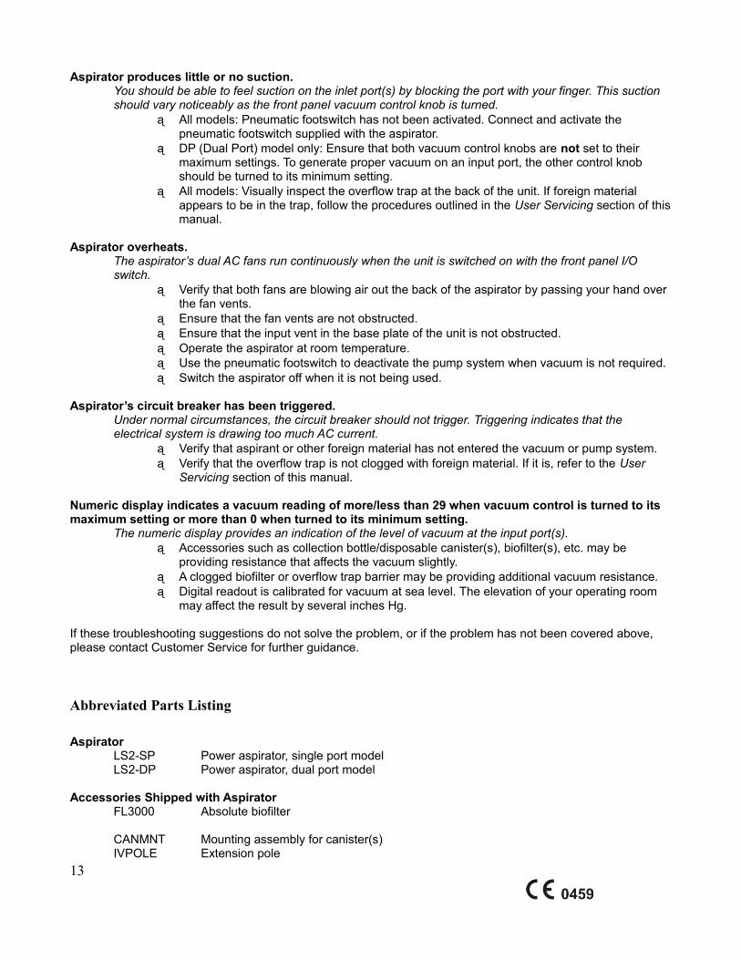
Aspirator produces little or no suction.You should be able to feel suction on the inlet port(s) by blocking the port with your finger. This suction should vary noticeably as the front panel vacuum control knob is turned.
All models: Pneumatic footswitch has not been activated. Connect and activate the pneumatic footswitch supplied with the aspirator.
DP (Dual Port) model only: Ensure that both vacuum control knobs are not set to their maximum settings. To generate proper vacuum on an input port, the other control knob should be turned to its minimum setting.
All models: Visually inspect the overflow trap at the back of the unit. If foreign material appears to be in the trap, follow the procedures outlined in the User Servicing section of this manual.
Aspirator overheats.The aspirator’s dual AC fans run continuously when the unit is switched on with the front panel I/O switch.
Verify that both fans are blowing air out the back of the aspirator by passing your hand over the fan vents.
Ensure that the fan vents are not obstructed. Ensure that the input vent in the base plate of the unit is not obstructed. Operate the aspirator at room temperature. Use the pneumatic footswitch to deactivate the pump system when vacuum is not required. Switch the aspirator off when it is not being used.
Aspirator’s circuit breaker has been triggered. Under normal circumstances, the circuit breaker should not trigger. Triggering indicates that the electrical system is drawing too much AC current.
Verify that aspirant or other foreign material has not entered the vacuum or pump system. Verify that the overflow trap is not clogged with foreign material. If it is, refer to the User
Servicing section of this manual.
Numeric display indicates a vacuum reading of more/less than 29 when vacuum control is turned to its maximum setting or more than 0 when turned to its minimum setting.
The numeric display provides an indication of the level of vacuum at the input port(s). Accessories such as collection bottle/disposable canister(s), biofilter(s), etc. may be
providing resistance that affects the vacuum slightly. A clogged biofilter or overflow trap barrier may be providing additional vacuum resistance. Digital readout is calibrated for vacuum at sea level. The elevation of your operating room
may affect the result by several inches Hg.
If these troubleshooting suggestions do not solve the problem, or if the problem has not been covered above, please contact Customer Service for further guidance.
Abbreviated Parts Listing
AspiratorLS2-SP Power aspirator, single port modelLS2-DP Power aspirator, dual port model
Accessories Shipped with AspiratorFL3000 Absolute biofilter
CANMNT Mounting assembly for canister(s)IVPOLE Extension pole
13
AS4500-P Pneumatic footswitch109-059 “Hospital grade” power cord165-027 LS2 user/service manual
Related AccessoriesLS7020 2000cc disposable implosion-proof canister (box of 10)LS7010 8’ length, sterile PVC tubingLS7012 10’ length, sterile PVC tubingCall Cannulae, various sizes and stylesCall Post-surgical garments, various sizes and styles
Replacement Parts164-007 Control valve165-023 Overflow trap assemblyAS1704 Overflow trap barrier
Requesting ServiceIf you would like to request service for your LS2, please contact Customer Service (see below).
M.D. Resource will assign an RMA (Return Material Authorization) number for the repair/return. Items returned without a valid RMA number will be refused.
Once you have received an RMA number, follow this procedure:1. Pack each item securely. M.D. Resource is not responsible for damage caused during a product’s
return.2. Write the RMA number on the outside of the package or on the accompanying paperwork.3. Return the item(s) to M.D. Resource’s corporate address using a reputable carrier, prepaid. Collect
shipments, etc. will be refused. You may wish to insure your shipment. It is strongly suggested that you use a carrier that provides proof of delivery.
Contact Information
Corporate AddressM.D. Resource Corporation5981 Graham CourtLivermore, CA 94550
Customer Service, Technical Support, and General Inquiries Telephone1-800-633-8423, or(510) 732-9950
Fax(510) 785-8182
14
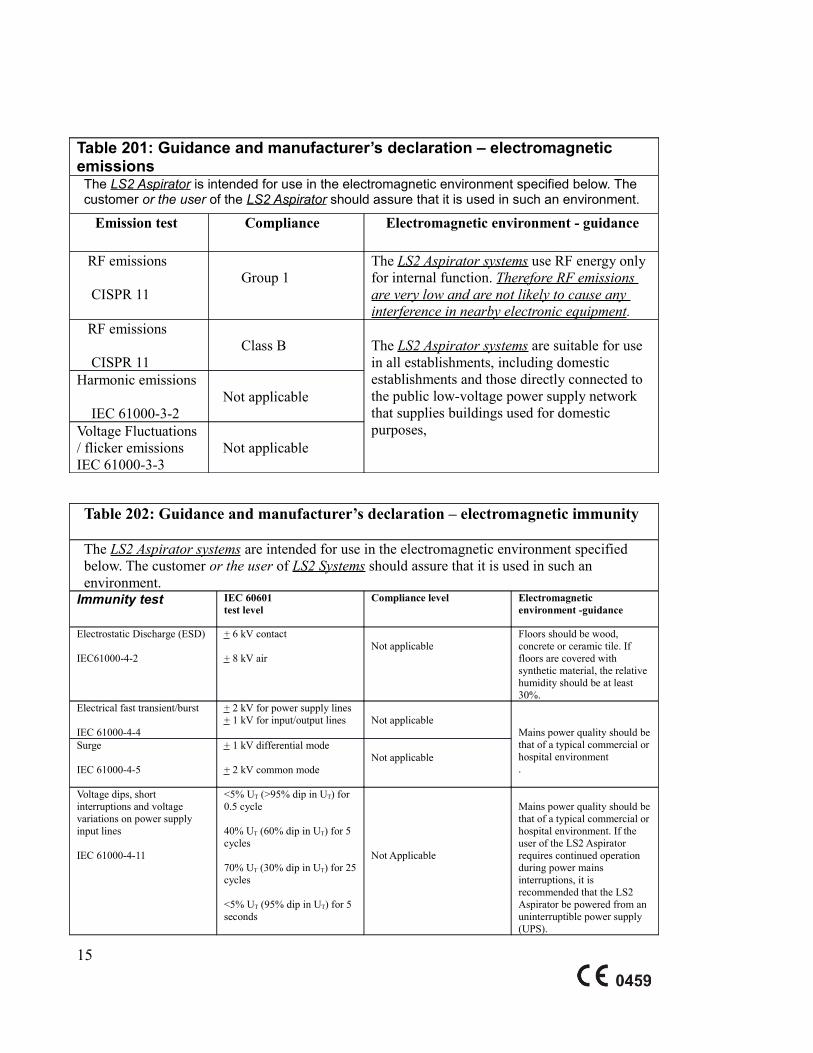
Table 201: Guidance and manufacturer’s declaration – electromagnetic emissionsThe LS2 Aspirator is intended for use in the electromagnetic environment specified below. The customer or the user of the LS2 Aspirator should assure that it is used in such an environment.
Emission test Compliance Electromagnetic environment - guidance
RF emissions
CISPR 11
Group 1
The LS2 Aspirator systems use RF energy only for internal function. Therefore RF emissions are very low and are not likely to cause any interference in nearby electronic equipment.
RF emissions
CISPR 11
Class B The LS2 Aspirator systems are suitable for use
in all establishments, including domestic establishments and those directly connected to the public low-voltage power supply network that supplies buildings used for domestic purposes,
Harmonic emissions
IEC 61000-3-2 Not applicable
Voltage Fluctuations/ flicker emissionsIEC 61000-3-3
Not applicable
Table 202: Guidance and manufacturer’s declaration – electromagnetic immunity
The LS2 Aspirator systems are intended for use in the electromagnetic environment specified below. The customer or the user of LS2 Systems should assure that it is used in such an environment.
Immunity test IEC 60601test level
Compliance level Electromagnetic environment -guidance
Electrostatic Discharge (ESD)
IEC61000-4-2
+ 6 kV contact
+ 8 kV airNot applicable
Floors should be wood, concrete or ceramic tile. If floors are covered with synthetic material, the relative humidity should be at least 30%.
Electrical fast transient/burst
IEC 61000-4-4
+ 2 kV for power supply lines+ 1 kV for input/output lines Not applicable
Mains power quality should be that of a typical commercial or hospital environment.
Surge
IEC 61000-4-5
+ 1 kV differential mode
+ 2 kV common modeNot applicable
Voltage dips, short interruptions and voltage variations on power supply input lines
IEC 61000-4-11
<5% UT (>95% dip in UT) for 0.5 cycle
40% UT (60% dip in UT) for 5 cycles
70% UT (30% dip in UT) for 25 cycles
<5% UT (95% dip in UT) for 5 seconds
Not Applicable
Mains power quality should be that of a typical commercial or hospital environment. If the user of the LS2 Aspirator requires continued operation during power mains interruptions, it is recommended that the LS2 Aspirator be powered from an uninterruptible power supply (UPS).
15
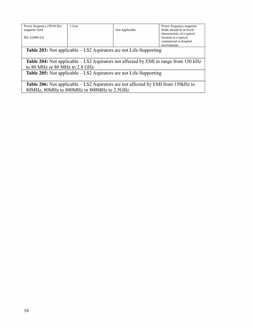
Power frequency (50/60 Hz) magnetic field
IEC 61000-4-8
3 A/mNot Applicable
Power frequency magnetic fields should be at levels characteristic of a typical location in a typical commercial or hospital environment.
Table 203: Not applicable – LS2 Aspirators are not Life-Supporting
Table 204: Not applicable – LS2 Aspirators not affected by EMI in range from 150 kHz to 80 MHz or 80 MHz to 2.8 GHzTable 205: Not applicable – LS2 Aspirators are not Life-Supporting
Table 206: Not applicable – LS2 Aspirators are not affected by EMI from 150kHz to 80MHz, 80MHz to 800MHz or 800MHz to 2.5GHz
16