Embed Size (px)
Citation preview
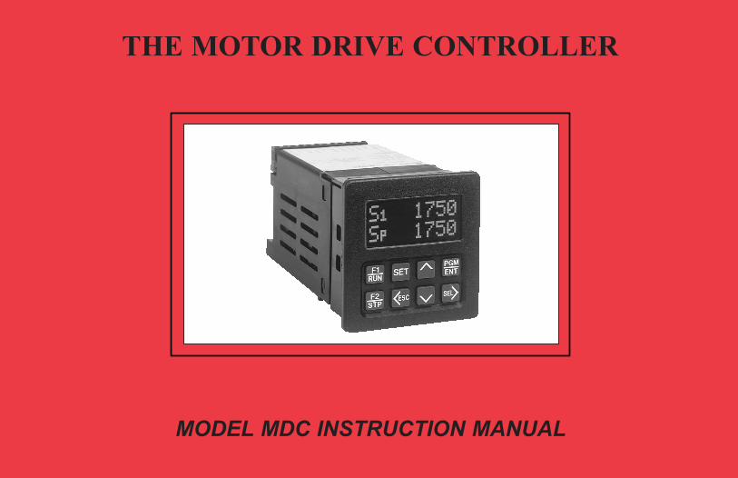
THE MOTOR DRIVE CONTROLLER
MODEL MDC INSTRUCTION MANUAL
MDC-COV.QXD 10/21/04 10:51 AM Page 1
INTRODUCTION
The Motor Drive Controller (MDC) is another unit in our multi-purpose series
of industrial control products that is field-programmable for solving various
applications. This series of products is built around the concept that the end user
has the capability to program different indication and control requirements.
The Motor Drive Controller which you have purchased, has the same high
quality workmanship and advanced technological capabilities that have made
Red Lion Controls the leader in today’s industrial market.
Red Lion Controls has a complete line of industrial indication and control
equipment, and we look forward to serving you now and in the future.
CAUTION: Read complete instructions prior
to installation and operation of the unit.
CAUTION: Risk of electric shock.
MDC-COV.QXD 10/21/04 10:51 AM Page 2
-1-
TABLE OF CONTENTS
I. GENERAL DESCRIPTION . . . . . . . . . . . . . . . . . . . . . . . . . . . . . . . . . . . . . . . . . . . . . . . . . . . . . . . . . . . . . . . . . . . . . . . . . . . . . . . . . . . . . . . . . . . 4-11A) Safety Summary . . . . . . . . . . . . . . . . . . . . . . . . . . . . . . . . . . . . . . . . . . . . . . . . . . . . . . . . . . . . . . . . . . . . . . . . . . . . . . . . . . . . . . . . . . . . . . . . . . . . . . . 4B) Quick Start - Setting Up The MDC . . . . . . . . . . . . . . . . . . . . . . . . . . . . . . . . . . . . . . . . . . . . . . . . . . . . . . . . . . . . . . . . . . . . . . . . . . . . . . . . . . . . . . . 5C) Block Diagram . . . . . . . . . . . . . . . . . . . . . . . . . . . . . . . . . . . . . . . . . . . . . . . . . . . . . . . . . . . . . . . . . . . . . . . . . . . . . . . . . . . . . . . . . . . . . . . . . . . . . . . . 6D) Theory of Operation . . . . . . . . . . . . . . . . . . . . . . . . . . . . . . . . . . . . . . . . . . . . . . . . . . . . . . . . . . . . . . . . . . . . . . . . . . . . . . . . . . . . . . . . . . . . . . . . . . . 7E) Normal Operating Mode . . . . . . . . . . . . . . . . . . . . . . . . . . . . . . . . . . . . . . . . . . . . . . . . . . . . . . . . . . . . . . . . . . . . . . . . . . . . . . . . . . . . . . . . . . . . . . . . 8F) Keypad Description . . . . . . . . . . . . . . . . . . . . . . . . . . . . . . . . . . . . . . . . . . . . . . . . . . . . . . . . . . . . . . . . . . . . . . . . . . . . . . . . . . . . . . . . . . . . . . . . . . . . 9
1. Keypad Functions . . . . . . . . . . . . . . . . . . . . . . . . . . . . . . . . . . . . . . . . . . . . . . . . . . . . . . . . . . . . . . . . . . . . . . . . . . . . . . . . . . . . . . . . . . . . . . . . . . . 9G) Dedicated Control Inputs . . . . . . . . . . . . . . . . . . . . . . . . . . . . . . . . . . . . . . . . . . . . . . . . . . . . . . . . . . . . . . . . . . . . . . . . . . . . . . . . . . . . . . . . . . . . . . . 10H) Front Panel Accessible Programming . . . . . . . . . . . . . . . . . . . . . . . . . . . . . . . . . . . . . . . . . . . . . . . . . . . . . . . . . . . . . . . . . . . . . . . . . . . . . . . . . . . . 10I) Overflow . . . . . . . . . . . . . . . . . . . . . . . . . . . . . . . . . . . . . . . . . . . . . . . . . . . . . . . . . . . . . . . . . . . . . . . . . . . . . . . . . . . . . . . . . . . . . . . . . . . . . . . . . . . . . 11
II. PROGRAMMING GENERAL DESCRIPTION . . . . . . . . . . . . . . . . . . . . . . . . . . . . . . . . . . . . . . . . . . . . . . . . . . . . . . . . . . . . . . . . . . . . . . . . . . 12III. USER SETPOINTS MODULE . . . . . . . . . . . . . . . . . . . . . . . . . . . . . . . . . . . . . . . . . . . . . . . . . . . . . . . . . . . . . . . . . . . . . . . . . . . . . . . . . . . . . . . . 13-15
A) User Setpoints In Master Mode . . . . . . . . . . . . . . . . . . . . . . . . . . . . . . . . . . . . . . . . . . . . . . . . . . . . . . . . . . . . . . . . . . . . . . . . . . . . . . . . . . . . . . . . . . 141. Speed Setpoint 1 . . . . . . . . . . . . . . . . . . . . . . . . . . . . . . . . . . . . . . . . . . . . . . . . . . . . . . . . . . . . . . . . . . . . . . . . . . . . . . . . . . . . . . . . . . . . . . . . . . . . 142. Speed Setpoint 2 . . . . . . . . . . . . . . . . . . . . . . . . . . . . . . . . . . . . . . . . . . . . . . . . . . . . . . . . . . . . . . . . . . . . . . . . . . . . . . . . . . . . . . . . . . . . . . . . . . . . 143. Ramp Rate 1 . . . . . . . . . . . . . . . . . . . . . . . . . . . . . . . . . . . . . . . . . . . . . . . . . . . . . . . . . . . . . . . . . . . . . . . . . . . . . . . . . . . . . . . . . . . . . . . . . . . . . . . 144. Ramp Rate 2 . . . . . . . . . . . . . . . . . . . . . . . . . . . . . . . . . . . . . . . . . . . . . . . . . . . . . . . . . . . . . . . . . . . . . . . . . . . . . . . . . . . . . . . . . . . . . . . . . . . . . . . 145. Jog Speed Setpoint . . . . . . . . . . . . . . . . . . . . . . . . . . . . . . . . . . . . . . . . . . . . . . . . . . . . . . . . . . . . . . . . . . . . . . . . . . . . . . . . . . . . . . . . . . . . . . . . . . 146. Jog Ramp Rate . . . . . . . . . . . . . . . . . . . . . . . . . . . . . . . . . . . . . . . . . . . . . . . . . . . . . . . . . . . . . . . . . . . . . . . . . . . . . . . . . . . . . . . . . . . . . . . . . . . . . 147. Alarm 1 Setpoint . . . . . . . . . . . . . . . . . . . . . . . . . . . . . . . . . . . . . . . . . . . . . . . . . . . . . . . . . . . . . . . . . . . . . . . . . . . . . . . . . . . . . . . . . . . . . . . . . . . 148. Alarm 2 Setpoint . . . . . . . . . . . . . . . . . . . . . . . . . . . . . . . . . . . . . . . . . . . . . . . . . . . . . . . . . . . . . . . . . . . . . . . . . . . . . . . . . . . . . . . . . . . . . . . . . . . 149. Error Gain Setpoint . . . . . . . . . . . . . . . . . . . . . . . . . . . . . . . . . . . . . . . . . . . . . . . . . . . . . . . . . . . . . . . . . . . . . . . . . . . . . . . . . . . . . . . . . . . . . . . . . 15
B) User Setpoints in Follower Mode. . . . . . . . . . . . . . . . . . . . . . . . . . . . . . . . . . . . . . . . . . . . . . . . . . . . . . . . . . . . . . . . . . . . . . . . . . . . . . . . . . . . . . . . . 151. Ratio Setpoint 1 . . . . . . . . . . . . . . . . . . . . . . . . . . . . . . . . . . . . . . . . . . . . . . . . . . . . . . . . . . . . . . . . . . . . . . . . . . . . . . . . . . . . . . . . . . . . . . . . . . . . 152. Ratio Setpoint 2 . . . . . . . . . . . . . . . . . . . . . . . . . . . . . . . . . . . . . . . . . . . . . . . . . . . . . . . . . . . . . . . . . . . . . . . . . . . . . . . . . . . . . . . . . . . . . . . . . . . . 153. Ramp Rate 1 . . . . . . . . . . . . . . . . . . . . . . . . . . . . . . . . . . . . . . . . . . . . . . . . . . . . . . . . . . . . . . . . . . . . . . . . . . . . . . . . . . . . . . . . . . . . . . . . . . . . . . . 154. Ramp Rate 2 . . . . . . . . . . . . . . . . . . . . . . . . . . . . . . . . . . . . . . . . . . . . . . . . . . . . . . . . . . . . . . . . . . . . . . . . . . . . . . . . . . . . . . . . . . . . . . . . . . . . . . . 15
IV PROGRAMMING MODULE . . . . . . . . . . . . . . . . . . . . . . . . . . . . . . . . . . . . . . . . . . . . . . . . . . . . . . . . . . . . . . . . . . . . . . . . . . . . . . . . . . . . . . . . . 16-30A) Operating Mode Selection Menu . . . . . . . . . . . . . . . . . . . . . . . . . . . . . . . . . . . . . . . . . . . . . . . . . . . . . . . . . . . . . . . . . . . . . . . . . . . . . . . . . . . . . . . . 16B) Program Scaling Menu . . . . . . . . . . . . . . . . . . . . . . . . . . . . . . . . . . . . . . . . . . . . . . . . . . . . . . . . . . . . . . . . . . . . . . . . . . . . . . . . . . . . . . . . . . . . . . . 17-18
1. Pulses per Revolution- Feedback . . . . . . . . . . . . . . . . . . . . . . . . . . . . . . . . . . . . . . . . . . . . . . . . . . . . . . . . . . . . . . . . . . . . . . . . . . . . . . . . . . . . . . 172. Maximum RPM- Feedback . . . . . . . . . . . . . . . . . . . . . . . . . . . . . . . . . . . . . . . . . . . . . . . . . . . . . . . . . . . . . . . . . . . . . . . . . . . . . . . . . . . . . . . . . . . 173. Display Decimal Point . . . . . . . . . . . . . . . . . . . . . . . . . . . . . . . . . . . . . . . . . . . . . . . . . . . . . . . . . . . . . . . . . . . . . . . . . . . . . . . . . . . . . . . . . . . . . . . 174. Display Units . . . . . . . . . . . . . . . . . . . . . . . . . . . . . . . . . . . . . . . . . . . . . . . . . . . . . . . . . . . . . . . . . . . . . . . . . . . . . . . . . . . . . . . . . . . . . . . . . . . . . . 175. Pulses per Revolution- Lead . . . . . . . . . . . . . . . . . . . . . . . . . . . . . . . . . . . . . . . . . . . . . . . . . . . . . . . . . . . . . . . . . . . . . . . . . . . . . . . . . . . . . . . . . . 186. Maximum RPM- Lead . . . . . . . . . . . . . . . . . . . . . . . . . . . . . . . . . . . . . . . . . . . . . . . . . . . . . . . . . . . . . . . . . . . . . . . . . . . . . . . . . . . . . . . . . . . . . . . 18

-2-
TABLE OF CONTENTS (Cont’d)
IV. PROGRAMMING MODULE (Cont’d) . . . . . . . . . . . . . . . . . . . . . . . . . . . . . . . . . . . . . . . . . . . . . . . . . . . . . . . . . . . . . . . . . . . . . . . . . . . . . . . . . 16-30C) Program User Menu . . . . . . . . . . . . . . . . . . . . . . . . . . . . . . . . . . . . . . . . . . . . . . . . . . . . . . . . . . . . . . . . . . . . . . . . . . . . . . . . . . . . . . . . . . . . . . . . . . 19-21
1. No Mode . . . . . . . . . . . . . . . . . . . . . . . . . . . . . . . . . . . . . . . . . . . . . . . . . . . . . . . . . . . . . . . . . . . . . . . . . . . . . . . . . . . . . . . . . . . . . . . . . . . . . . . . . . 202. View Display . . . . . . . . . . . . . . . . . . . . . . . . . . . . . . . . . . . . . . . . . . . . . . . . . . . . . . . . . . . . . . . . . . . . . . . . . . . . . . . . . . . . . . . . . . . . . . . . . . . . . . . 203. Change Display . . . . . . . . . . . . . . . . . . . . . . . . . . . . . . . . . . . . . . . . . . . . . . . . . . . . . . . . . . . . . . . . . . . . . . . . . . . . . . . . . . . . . . . . . . . . . . . . . . . . . 204. Reset Alarms . . . . . . . . . . . . . . . . . . . . . . . . . . . . . . . . . . . . . . . . . . . . . . . . . . . . . . . . . . . . . . . . . . . . . . . . . . . . . . . . . . . . . . . . . . . . . . . . . . . . . . . 205. Setpoint Select/Toggle . . . . . . . . . . . . . . . . . . . . . . . . . . . . . . . . . . . . . . . . . . . . . . . . . . . . . . . . . . . . . . . . . . . . . . . . . . . . . . . . . . . . . . . . . . . . . . . 206. Ramp Select/Toggle . . . . . . . . . . . . . . . . . . . . . . . . . . . . . . . . . . . . . . . . . . . . . . . . . . . . . . . . . . . . . . . . . . . . . . . . . . . . . . . . . . . . . . . . . . . . . . . . . 207. Ramp Override . . . . . . . . . . . . . . . . . . . . . . . . . . . . . . . . . . . . . . . . . . . . . . . . . . . . . . . . . . . . . . . . . . . . . . . . . . . . . . . . . . . . . . . . . . . . . . . . . . . . . 208. Setpoint Increment . . . . . . . . . . . . . . . . . . . . . . . . . . . . . . . . . . . . . . . . . . . . . . . . . . . . . . . . . . . . . . . . . . . . . . . . . . . . . . . . . . . . . . . . . . . . . . . . . . 219. Setpoint Decrement . . . . . . . . . . . . . . . . . . . . . . . . . . . . . . . . . . . . . . . . . . . . . . . . . . . . . . . . . . . . . . . . . . . . . . . . . . . . . . . . . . . . . . . . . . . . . . . . . . 21
10. Program Disable . . . . . . . . . . . . . . . . . . . . . . . . . . . . . . . . . . . . . . . . . . . . . . . . . . . . . . . . . . . . . . . . . . . . . . . . . . . . . . . . . . . . . . . . . . . . . . . . . . . . 2111. Run . . . . . . . . . . . . . . . . . . . . . . . . . . . . . . . . . . . . . . . . . . . . . . . . . . . . . . . . . . . . . . . . . . . . . . . . . . . . . . . . . . . . . . . . . . . . . . . . . . . . . . . . . . . . . . . 2112. Ramp Stop . . . . . . . . . . . . . . . . . . . . . . . . . . . . . . . . . . . . . . . . . . . . . . . . . . . . . . . . . . . . . . . . . . . . . . . . . . . . . . . . . . . . . . . . . . . . . . . . . . . . . . . . . 2113. Fast Stop. . . . . . . . . . . . . . . . . . . . . . . . . . . . . . . . . . . . . . . . . . . . . . . . . . . . . . . . . . . . . . . . . . . . . . . . . . . . . . . . . . . . . . . . . . . . . . . . . . . . . . . . . . . 2114. Jog . . . . . . . . . . . . . . . . . . . . . . . . . . . . . . . . . . . . . . . . . . . . . . . . . . . . . . . . . . . . . . . . . . . . . . . . . . . . . . . . . . . . . . . . . . . . . . . . . . . . . . . . . . . . . . . . 21
D) Program Alarms Menu . . . . . . . . . . . . . . . . . . . . . . . . . . . . . . . . . . . . . . . . . . . . . . . . . . . . . . . . . . . . . . . . . . . . . . . . . . . . . . . . . . . . . . . . . . . . . . . . 22-231. Alarm Types . . . . . . . . . . . . . . . . . . . . . . . . . . . . . . . . . . . . . . . . . . . . . . . . . . . . . . . . . . . . . . . . . . . . . . . . . . . . . . . . . . . . . . . . . . . . . . . . . . . . . . . 22
a. High . . . . . . . . . . . . . . . . . . . . . . . . . . . . . . . . . . . . . . . . . . . . . . . . . . . . . . . . . . . . . . . . . . . . . . . . . . . . . . . . . . . . . . . . . . . . . . . . . . . . . . . . . . . . 22b. Low. . . . . . . . . . . . . . . . . . . . . . . . . . . . . . . . . . . . . . . . . . . . . . . . . . . . . . . . . . . . . . . . . . . . . . . . . . . . . . . . . . . . . . . . . . . . . . . . . . . . . . . . . . . . . 22c. Deviation . . . . . . . . . . . . . . . . . . . . . . . . . . . . . . . . . . . . . . . . . . . . . . . . . . . . . . . . . . . . . . . . . . . . . . . . . . . . . . . . . . . . . . . . . . . . . . . . . . . . . . . . 22d. Zero Speed. . . . . . . . . . . . . . . . . . . . . . . . . . . . . . . . . . . . . . . . . . . . . . . . . . . . . . . . . . . . . . . . . . . . . . . . . . . . . . . . . . . . . . . . . . . . . . . . . . . . . . . 22e. Disabled . . . . . . . . . . . . . . . . . . . . . . . . . . . . . . . . . . . . . . . . . . . . . . . . . . . . . . . . . . . . . . . . . . . . . . . . . . . . . . . . . . . . . . . . . . . . . . . . . . . . . . . . . 22
2. Phase (+ or -) . . . . . . . . . . . . . . . . . . . . . . . . . . . . . . . . . . . . . . . . . . . . . . . . . . . . . . . . . . . . . . . . . . . . . . . . . . . . . . . . . . . . . . . . . . . . . . . . . . . . . . . 233. Boundary or Latched. . . . . . . . . . . . . . . . . . . . . . . . . . . . . . . . . . . . . . . . . . . . . . . . . . . . . . . . . . . . . . . . . . . . . . . . . . . . . . . . . . . . . . . . . . . . . . . . . 234. Normal or Fast Update Time . . . . . . . . . . . . . . . . . . . . . . . . . . . . . . . . . . . . . . . . . . . . . . . . . . . . . . . . . . . . . . . . . . . . . . . . . . . . . . . . . . . . . . . . . . 235. Stop Enabled or Disabled . . . . . . . . . . . . . . . . . . . . . . . . . . . . . . . . . . . . . . . . . . . . . . . . . . . . . . . . . . . . . . . . . . . . . . . . . . . . . . . . . . . . . . . . . . . . . 23
E) Program Displays Menu . . . . . . . . . . . . . . . . . . . . . . . . . . . . . . . . . . . . . . . . . . . . . . . . . . . . . . . . . . . . . . . . . . . . . . . . . . . . . . . . . . . . . . . . . . . . . . . 24-251. Displays 1 to 4 . . . . . . . . . . . . . . . . . . . . . . . . . . . . . . . . . . . . . . . . . . . . . . . . . . . . . . . . . . . . . . . . . . . . . . . . . . . . . . . . . . . . . . . . . . . . . . . . . . . . . . 242. Scroll Speed . . . . . . . . . . . . . . . . . . . . . . . . . . . . . . . . . . . . . . . . . . . . . . . . . . . . . . . . . . . . . . . . . . . . . . . . . . . . . . . . . . . . . . . . . . . . . . . . . . . . . . . . 24
F) Program Options Menu . . . . . . . . . . . . . . . . . . . . . . . . . . . . . . . . . . . . . . . . . . . . . . . . . . . . . . . . . . . . . . . . . . . . . . . . . . . . . . . . . . . . . . . . . . . . . . . . 26-281. Operator Access . . . . . . . . . . . . . . . . . . . . . . . . . . . . . . . . . . . . . . . . . . . . . . . . . . . . . . . . . . . . . . . . . . . . . . . . . . . . . . . . . . . . . . . . . . . . . . . . . . . . 262. Feedback Loss Detection . . . . . . . . . . . . . . . . . . . . . . . . . . . . . . . . . . . . . . . . . . . . . . . . . . . . . . . . . . . . . . . . . . . . . . . . . . . . . . . . . . . . . . . . . . . . . 263. User Settings . . . . . . . . . . . . . . . . . . . . . . . . . . . . . . . . . . . . . . . . . . . . . . . . . . . . . . . . . . . . . . . . . . . . . . . . . . . . . . . . . . . . . . . . . . . . . . . . . . . . . . . 274. MDC Factory Settings . . . . . . . . . . . . . . . . . . . . . . . . . . . . . . . . . . . . . . . . . . . . . . . . . . . . . . . . . . . . . . . . . . . . . . . . . . . . . . . . . . . . . . . . . . . . . . . 275. MDC User Setting Chart . . . . . . . . . . . . . . . . . . . . . . . . . . . . . . . . . . . . . . . . . . . . . . . . . . . . . . . . . . . . . . . . . . . . . . . . . . . . . . . . . . . . . . . . . . . . . 28
-3-
TABLE OF CONTENTS (Cont’d)
IV. PROGRAMMING MODULE (Cont’d) . . . . . . . . . . . . . . . . . . . . . . . . . . . . . . . . . . . . . . . . . . . . . . . . . . . . . . . . . . . . . . . . . . . . . . . . . . . . . . . . . 16-30G) Program Diagnostics Menu . . . . . . . . . . . . . . . . . . . . . . . . . . . . . . . . . . . . . . . . . . . . . . . . . . . . . . . . . . . . . . . . . . . . . . . . . . . . . . . . . . . . . . . . . . . . 29-30
1. Test Inputs . . . . . . . . . . . . . . . . . . . . . . . . . . . . . . . . . . . . . . . . . . . . . . . . . . . . . . . . . . . . . . . . . . . . . . . . . . . . . . . . . . . . . . . . . . . . . . . . . . . . . . . . . 292. Test Alarms . . . . . . . . . . . . . . . . . . . . . . . . . . . . . . . . . . . . . . . . . . . . . . . . . . . . . . . . . . . . . . . . . . . . . . . . . . . . . . . . . . . . . . . . . . . . . . . . . . . . . . . . 303. Test Drive Output . . . . . . . . . . . . . . . . . . . . . . . . . . . . . . . . . . . . . . . . . . . . . . . . . . . . . . . . . . . . . . . . . . . . . . . . . . . . . . . . . . . . . . . . . . . . . . . . . . . 30
H) Program Security Menu . . . . . . . . . . . . . . . . . . . . . . . . . . . . . . . . . . . . . . . . . . . . . . . . . . . . . . . . . . . . . . . . . . . . . . . . . . . . . . . . . . . . . . . . . . . . . . . . 301. Select Security Code . . . . . . . . . . . . . . . . . . . . . . . . . . . . . . . . . . . . . . . . . . . . . . . . . . . . . . . . . . . . . . . . . . . . . . . . . . . . . . . . . . . . . . . . . . . . . . . . . 30
VII. INSTALLATION & CONNECTIONS . . . . . . . . . . . . . . . . . . . . . . . . . . . . . . . . . . . . . . . . . . . . . . . . . . . . . . . . . . . . . . . . . . . . . . . . . . . . . . . . . 31-38A) Installation Environment. . . . . . . . . . . . . . . . . . . . . . . . . . . . . . . . . . . . . . . . . . . . . . . . . . . . . . . . . . . . . . . . . . . . . . . . . . . . . . . . . . . . . . . . . . . . . . . . 32B) Terminal Connection Drawing . . . . . . . . . . . . . . . . . . . . . . . . . . . . . . . . . . . . . . . . . . . . . . . . . . . . . . . . . . . . . . . . . . . . . . . . . . . . . . . . . . . . . . . . . . . 33C) Wiring Connections . . . . . . . . . . . . . . . . . . . . . . . . . . . . . . . . . . . . . . . . . . . . . . . . . . . . . . . . . . . . . . . . . . . . . . . . . . . . . . . . . . . . . . . . . . . . . . . . . . . . 33
1. AC Power Wiring . . . . . . . . . . . . . . . . . . . . . . . . . . . . . . . . . . . . . . . . . . . . . . . . . . . . . . . . . . . . . . . . . . . . . . . . . . . . . . . . . . . . . . . . . . . . . . . . . . . 332. DC Output Power Wiring . . . . . . . . . . . . . . . . . . . . . . . . . . . . . . . . . . . . . . . . . . . . . . . . . . . . . . . . . . . . . . . . . . . . . . . . . . . . . . . . . . . . . . . . . . . . . 34
D) Signal Wiring . . . . . . . . . . . . . . . . . . . . . . . . . . . . . . . . . . . . . . . . . . . . . . . . . . . . . . . . . . . . . . . . . . . . . . . . . . . . . . . . . . . . . . . . . . . . . . . . . . . . . . . 34-361. Lead & Feedback Frequency Inputs . . . . . . . . . . . . . . . . . . . . . . . . . . . . . . . . . . . . . . . . . . . . . . . . . . . . . . . . . . . . . . . . . . . . . . . . . . . . . . . . . . . . 342. Dedicated Function and User Inputs . . . . . . . . . . . . . . . . . . . . . . . . . . . . . . . . . . . . . . . . . . . . . . . . . . . . . . . . . . . . . . . . . . . . . . . . . . . . . . . . . . . . 353. Alarm Outputs 1 and 2 . . . . . . . . . . . . . . . . . . . . . . . . . . . . . . . . . . . . . . . . . . . . . . . . . . . . . . . . . . . . . . . . . . . . . . . . . . . . . . . . . . . . . . . . . . . . . . . 354. Drive Enable Output . . . . . . . . . . . . . . . . . . . . . . . . . . . . . . . . . . . . . . . . . . . . . . . . . . . . . . . . . . . . . . . . . . . . . . . . . . . . . . . . . . . . . . . . . . . . . . . . . 355. Isolated Drive Output . . . . . . . . . . . . . . . . . . . . . . . . . . . . . . . . . . . . . . . . . . . . . . . . . . . . . . . . . . . . . . . . . . . . . . . . . . . . . . . . . . . . . . . . . . . . . . . . 36
E) DIP Switch Set-up . . . . . . . . . . . . . . . . . . . . . . . . . . . . . . . . . . . . . . . . . . . . . . . . . . . . . . . . . . . . . . . . . . . . . . . . . . . . . . . . . . . . . . . . . . . . . . . . . . . . . 36VIII. ISOLATED DRIVE OUTPUT CALIBRATION . . . . . . . . . . . . . . . . . . . . . . . . . . . . . . . . . . . . . . . . . . . . . . . . . . . . . . . . . . . . . . . . . . . . . . . . . . 39
A) Drive Output Span Calibration. . . . . . . . . . . . . . . . . . . . . . . . . . . . . . . . . . . . . . . . . . . . . . . . . . . . . . . . . . . . . . . . . . . . . . . . . . . . . . . . . . . . . . . . . . . 39B) Motor Drive Setup . . . . . . . . . . . . . . . . . . . . . . . . . . . . . . . . . . . . . . . . . . . . . . . . . . . . . . . . . . . . . . . . . . . . . . . . . . . . . . . . . . . . . . . . . . . . . . . . . . . . . 39C) Verify System Operation . . . . . . . . . . . . . . . . . . . . . . . . . . . . . . . . . . . . . . . . . . . . . . . . . . . . . . . . . . . . . . . . . . . . . . . . . . . . . . . . . . . . . . . . . . . . . . . 39D) Trim . . . . . . . . . . . . . . . . . . . . . . . . . . . . . . . . . . . . . . . . . . . . . . . . . . . . . . . . . . . . . . . . . . . . . . . . . . . . . . . . . . . . . . . . . . . . . . . . . . . . . . . . . . . . . . . . 39
IX. SPECIFICATIONS & DIMENSIONS . . . . . . . . . . . . . . . . . . . . . . . . . . . . . . . . . . . . . . . . . . . . . . . . . . . . . . . . . . . . . . . . . . . . . . . . . . . . . . . . . 40-41X. TROUBLESHOOTING. . . . . . . . . . . . . . . . . . . . . . . . . . . . . . . . . . . . . . . . . . . . . . . . . . . . . . . . . . . . . . . . . . . . . . . . . . . . . . . . . . . . . . . . . . . . . . . 42-44XI. APPENDIX “A” - APPLICATIONS . . . . . . . . . . . . . . . . . . . . . . . . . . . . . . . . . . . . . . . . . . . . . . . . . . . . . . . . . . . . . . . . . . . . . . . . . . . . . . . . . . . 45-46
A) MASTER MODE APPLICATION . . . . . . . . . . . . . . . . . . . . . . . . . . . . . . . . . . . . . . . . . . . . . . . . . . . . . . . . . . . . . . . . . . . . . . . . . . . . . . . . . . . . . . . 45B) FOLLOWER MODE APPLICATION. . . . . . . . . . . . . . . . . . . . . . . . . . . . . . . . . . . . . . . . . . . . . . . . . . . . . . . . . . . . . . . . . . . . . . . . . . . . . . . . . . . . . 46
XII. APPENDIX “B” - ORDERING INFORMATION . . . . . . . . . . . . . . . . . . . . . . . . . . . . . . . . . . . . . . . . . . . . . . . . . . . . . . . . . . . . . . . . . . . . . . . . . 47XIII. APPENDIX “C” - FLOWCHART FOLD-OUT (Insert). . . . . . . . . . . . . . . . . . . . . . . . . . . . . . . . . . . . . . . . . . . . . . . . . . . . . . . . . . . . . . . . . . . . �
GENERAL DESCRIPTIONThe Motor Drive Controller (MDC) accurately regulates motor speed by
varying an isolated DC control signal to a motor drive system. There are twomodes of operation, Master and Follower.
Master Mode provides control of a motor directly via programmed speedsetpoints in the MDC. Regulation is maintained by means of a feedbackfrequency to the MDC taken from the motor shaft or a downstream shaft pulseencoder. Follower Mode controls a motor’s speed as a ratio to a secondmotor’s speed or outside frequency source. The MDC is a “speed” follower. Itdoes not track the lead motor’s position. Ratio setpoints are programmed intothe unit causing the motor to “follow” the lead motor’s speed at a fixed ratio.
The MDC has two programmable speed setpoints and two ramp setpointsin master mode. Follower Mode has two ratio setpoints and two rampsetpoints. Both modes share a jog speed setpoint and a jog ramp setpoint. Allsetpoints are retained in non-volatile memory when the unit is powered down.
There are five dedicated control inputs on the MDC:
RUN
RAMP STOP
FAST STOP
JOG
OPEN LOOP
There are six programmable control inputs: two front panel function keysand four remote User Inputs. The F1 and F2 keys are factory programmed forRUN and R-STOP respectively. This eliminates the need for externalswitches in some applications.
There are three solid state outputs, two are programmable and one is adedicated DRIVE ENABLE output. Programmable functions include:
HIGH ALARM
LOW ALARM
DEVIATION ALARM
ZERO SPEED
DISABLED
Outputs may be programmed for boundary or latching operation, and highor low acting. There are also two programmable alarm update rates, Normaland Fast.
Application flexibility is provided through the two-line by eight-characteralphanumeric display. The display features English language menus for easyviewing and simplified programming. The four scroll-through IndicationDisplays can be programmed to show various parameters and toautomatically scroll, if desired. A program disable DIP switch used with anexternal User Input can be utilized to protect the settings and guarantee thatno unwanted changes occur during operation.
Changing speed setpoints and programming information is easilyaccomplished by scrolling through menus and selecting the correctparameter. There are three main Modules:
INDICATION DISPLAY MODULE
USER SETPOINTS MODULE
PROGRAMMING MODULE
Scaling is accomplished by entering the number of feedback pulses perrevolution (PPR), the maximum RPM, and the maximum display units. TheMDC is factory configured for an isolated 0 to 10 VDC drive output signal.The drive output signal can be adjusted to span from 0 to a maximum of 5through 15 VDC via an accessible potentiometer. The drive output is jumperselectable for an external reference voltage. To use the external reference, theMDC is connected to the drive in place of an external speed potentiometer.
The construction of the MDC unit is a lightweight, high impact plastic casewith a clear viewing window. The sealed front panel with the silicone rubberkeypad meets NEMA 4X/IP65 specifications for wash-down and/or dustyenvironments, when properly installed. Plug-in style terminal blockssimplify installation and wiring change-outs.
SAFETY SUMMARYAll safety related regulations, local codes and instructions that appear in
the manual or on equipment must be observed to ensure personal safety and toprevent damage to either the instrument or equipment connected to it. Ifequipment is used in a manner not specified by the manufacturer, theprotection provided by the equipment may be impaired.
Do not use this unit to directly command motors, valves, or other actuatorsnot equipped with safeguards. To do so, can be potentially harmful to personsor equipment in the event of a fault to the unit.
-4-
QUICK START - SETTING UP THE MDCWhile it is generally recommended that you read this instruction manual
thoroughly before attempting to set up and operate the model MDC MotorDrive Controller, the following quick set-up procedure provides the basicsteps to get the MDC up and running.
1. Read “General Description” and “Block Diagram” to familiarize yourselfwith the Basic Connections. (A/C, Inputs, Outputs, etc).
2. Wire or set the Control Inputs to their proper states:
- RUN may be left open for front panel control, or wired to commonthrough a momentary, normally OPEN switch for remoteoperation.
- R-STOP may be tied to common for front panel control, or wired tocommon through a momentary, normally CLOSED switch forremote operation.
- F-STOP must be tied to common or wired to common through amomentary, normally CLOSED switch.
- JOG must be left open or wired to a momentary, normally OPEN switchrequiring a sustained closure for Jog mode.
- OPEN LOOP must be left open for normal closed loop control, or wiredto a switch which can be maintained in the open or closed position,depending on User preference.
Refer to “Dedicated Control Function and User Inputs” in the “Installationand Connections” section for more information.
3. Set the AC power selection switch and connect AC to the MDC as noted in“AC Power Wiring” in the “Installation and Connections” section.
4. Review “Programming General Description” and “Keypad Description” tofamiliarize yourself with the Front Panel Programming procedure.
5. To set up the MDC for Master Mode - Program the scaling variables forPPR FB, MAX RPM FB, DSP DP, and DSP UNIT. Refer to the “ProgramScaling Menu”.
6. To set up the MDC for Follower Mode - Select Follower Mode in theOperating Mode Selection Menu. Program the scaling variables for PPRFB, MAX RPM FB, DSP DP, and DSP UNIT. Refer to “Program ScalingMenu”. Pay particular attention to “Additional Scale Factors in FollowerMode”. This will explain the two additional required variables PPR LD and
RPM LD, which are part of setting the Unity Ratio. Understanding theUnity Ratio is crucial to scaling in Follower Mode.
7. Refer to “Isolated Drive Output Calibration” section to determine if theMDC Drive Output span needs to be calibrated. Most applications requirecalibration of the drive only. Calibrate the drive as noted in “Motor DriveSetup”.
8. Disconnect AC power. Wire the MDC to the motor drive. Refer to “Wiringfrom MDC to Motor Drive” in the “Installation and Connections” section.
9. Wire the FEEDBACK and LEAD (follower mode only) frequency inputs.Set the DIP Switches as required. Refer to the “Installation andConnections” section.
10. Apply power to the MDC and Drive.
11. To run the motor, connect the RUN Input to common momentarily orpress the F1\RUN key, located on the Front Panel. The MDC will run themotor to the selected setpoint using the currently selected ramp rate. If thesetpoint is changed during Run Mode using the Front Panel Keypad or aremote input, the MDC will either accelerate or decelerate the motor to thenew setpoint using the current ramp rate.
12. To stop the motor, momentarily disconnect the R-Stop Input fromcommon or press the “F2/STP” key, located on the Front Panel. The MDCwill decelerate the motor using the currently selected ramp rate.
13. Disconnecting F-Stop momentarily from common will cause the MDC totake the Drive Output voltage immediately to zero volts. This will causethe motor to execute a Fast Stop uncontrolled by the ramp rate. If theF-Stop Input remains open from common, the Run and Jog inputs aredisabled and the Drive Output voltage is fixed at zero volts. A maintainedswitch should be used on the F-Stop input if this type of lock out is desired.
-5-
-6-
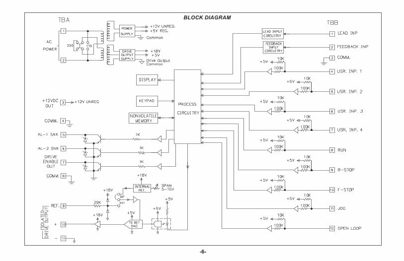
BLOCK DIAGRAM
THEORY OF OPERATIONIn Master Mode, the MDC uses actual motor speed (Feedback Input) and an
analog control voltage (Drive Output) to precisely control the motor’s speed.The MDC operates on a 10 msec control cycle. Actual motor speed is read anddrive output is corrected every 10 msec. The Drive Output voltage isgenerated by a 12 bit DAC (digital to analog converter). Motor speed iscontrolled by adjusting the Output Value (in bits) to the DAC.
The Output Value (0 to 4095 bits) is made up of two parts, the Open Loopterm, and the correction term or Trim Value. The Open Loop term is the ratioof the Reference Speed to Maximum Speed multiplied by 4095. This is theuncorrected “Feed Forward” part of the Output Value. The Reference Speedis the current Speed setpoint taking into account any acceleration ordeceleration which may be in progress. The Maximum Speed is Max RPMFeedback which is set when scaling the unit. (See the Program Scaling sectionof the manual for more information.)
The correction term or Trim Value is derived from actual motor speed(Feedback Input) and the Reference Speed. The Trim Value is added to theOpen Loop term when the MDC is running Closed Loop to provide precisecontrol. The Error Gain determines the rate at which the Trim Value changesin response to a motor loading or a sudden speed change. The Trim Value isupdated every 10 msec. It may be viewed as one of the programmable displayoptions (see Program Displays Menu).
The Drive Output voltage is then the ratio of Output Value (in bits) to 4095multiplied by the Full Scale Reference voltage. The internal Full ScaleReference is factory calibrated to 10 VDC but may be adjusted to any valuewithin a 5 to 15 VDC range. An external reference option also exists. (SeeIsolated Drive Output section of manual for more information.)
In Follower Mode, the basic operation is the same except that theReference Speed is generated as a ratio to the Lead Input speed. Also, theMDC operates on a 20 msec control cycle in order to process both Lead andFeedback input frequencies.
-7-
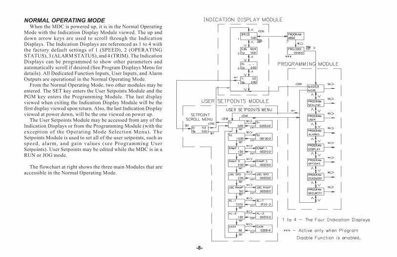
NORMAL OPERATING MODEWhen the MDC is powered up, it is in the Normal Operating
Mode with the Indication Display Module viewed. The up anddown arrow keys are used to scroll through the IndicationDisplays. The Indication Displays are referenced as 1 to 4 withthe factory default settings of 1 (SPEED), 2 (OPERATINGSTATUS), 3 (ALARM STATUS), and 4 (TRIM). The IndicationDisplays can be programmed to show other parameters andautomatically scroll if desired (See Program Displays Menu fordetails). All Dedicated Function Inputs, User Inputs, and AlarmOutputs are operational in the Normal Operating Mode.
From the Normal Operating Mode, two other modules may beentered. The SET key enters the User Setpoints Module and thePGM key enters the Programming Module. The last displayviewed when exiting the Indication Display Module will be thefirst display viewed upon return. Also, the last Indication Displayviewed at power down, will be the one viewed on power up.
The User Setpoints Module may be accessed from any of theIndication Displays or from the Programming Module (with theexception of the Operating Mode Selection Menu). TheSetpoints Module is used to set all of the user setpoints, such asspeed, alarm, and gain values (see Programming UserSetpoints). User Setpoints may be edited while the MDC is in aRUN or JOG mode.
The flowchart at right shows the three main Modules that areaccessible in the Normal Operating Mode.
-8-
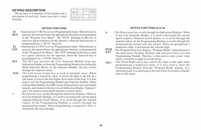
KEYPAD DESCRIPTIONShown here is a diagram of the keypad and a
description of each key. Some keys have a dualfunction.
KEYPAD FUNCTIONS KEYPAD FUNCTIONS (Cont’d)
-9-
v
PGM
ENT
SEL>
- The Down arrow key scrolls through the Indication Displays. Whenin the User Setpoints Module, it is used to decrement the currentspeed setpoint (Setpoint Scroll Menu), or to scroll through thesetpoint values. In the Programming Module, it scrolls through theprogramming menus and sub menus. When programming anumerical value, it decrements the selected digit.
- The Program/Enter key displays “Program Mode” when pressed inthe Indication Display Module and initiates entry into theProgramming Module. This key is also used to store a new valuewhen a selection is made in an edit menu.
- The Select/Right arrow key selects the digit to the right whenprogramming a numerical value. It is also used to enter theProgramming Module from the “Program Mode” display. In asub-menu loop, it is used to go to the next lower level and eventuallyinto an edit menu.
F1
RUN
F2
STP
SET
<ESC
�
- Function key F1/RUN is a User Programmable Input. When the key ispressed, the unit performs the appropriate function as programmedin the “Program User Menu”. The “RUN” printing on this key isused as a quick reference for the operator, when the function key isprogrammed for a “RUN” function.
- Function key F2/STP is a User Programmable Input. When the key ispressed, the unit performs the appropriate function, as programmedin the “Program User Menu”. The “STP” printing on this key is usedas a quick reference for the operator, when the function key isprogrammed for a “STOP” function.
- The SET key accesses the User Setpoints Module from anyIndication Display or from the Programming Module (excluding theMode Selection Menu). In the Setpoints Module, this key scrollsthrough the setpoint values.
- The Left arrow/escape key is used in multiple ways. Whenprogramming a numerical value, it selects the digit to the left. In asub-menu, it exits to the next higher level menu in the loop. It is alsoused to exit the Programming Module and Setpoints Module. Whenexiting either Module, the MDC stores all parameters into nonvolatilememory and returns to the last viewed Indication Display. Setpoint 1and 2 are stored in nonvolatile memory at power down.
- The Up arrow key scrolls through the Indication Displays. When inthe User Setpoints Module, it is used to increment the current speedsetpoint (Setpoint Scroll Menu), or to scroll through the setpointvalues. In the Programming Module, it scrolls through theprogramming menus. When programming a numerical value, itincrements the selected digit.
DEDICATED CONTROL INPUT FUNCTIONSThe Motor Drive has inputs dedicated to certain primary operations. These
functions are as follows:
RUNA momentary closure to common on the RUN input causes the MDC to
accelerate the motor from STOP mode to the current speed setpoint using thecurrent ramp rate.
R-STOPA momentary open from common on the R-STOP input causes the MDC to
decelerate the motor from its current speed to STOP mode using the currentramp rate.
F-STOPA momentary open from common on the F-STOP input causes the MDC to
execute a fast stop, taking the analog Drive Output signal immediately to zerovolts. Motor deceleration is limited only by the motor drive system. This is anemergency stop function. The Drive Enable Output goes immediately to itsinactive state and may be used to engage braking or remove power from themotor via an external relay.
JOGThe jog function only operates from the STOP mode. A sustained closure
from the JOG input to common causes the MDC to accelerate the motor to thejog speed setpoint using the jog ramp rate. The motor remains at the jog speeduntil the closure is removed, at which point the MDC executes an F-STOP.
OPEN LOOPA maintained closure to common on this input causes the MDC to run open
loop. The error correction value, Trim, is set to zero and speed is notregulated. A momentary closure on this input can be used as a Trim reset, tomomentarily reset the Trim value to zero.
Note: Feedback Loss Detection is automatically disabled in Open Loop Mode.
FRONT PANEL ACCESSIBLE PROGRAMMINGThe MDC has several ways to limit the programming of parameters in the
User Setpoints Module and the Programming Module. The Operator AccessMenu, in the Programming Module, can be used with the Program Disable(PGM. DIS) DIP switch or an external User Input to limit programming ofparameters in the User Setpoints Module.
To enter the Programming Module, a program code number may need to beentered, depending on the Program Disable Function setting. Only externalUser Inputs can be selected for program disable. The default value for theprogram code number is “00”, but should be programmed differently (SeeProgram Security Menu). This helps prevent inadvertent entry into the unit’sprogramming modules. When PROGRAM MODE is displayed and then theSEL key is pressed, the PRO.CODE prompt will be viewed. At this time, theCode number must be entered using the arrow keys. After selecting the propercode number and pressing the Enter key, the operator advances into theProgramming Module. If the wrong code number is entered, the operator willnot be able to enter the Programming Module and the unit returns to thePROGRAM MODE display. The following list describes the possibleprogram disabling functions.
PGM.DISSWITCH
USER INPUTTERMINAL
PROGRAMCODE
NUMBERACTION
OFF INACTIVE or Not
Programmed for
PGM.DIS
N/A Complete programming enabled.
OFF ACTIVE 0 to 98 Operator Accessible Functions,Programming Loop Accessible viaCode number.
OFF ACTIVE 99 Operator Accessible Functions,Programming Loop Disabled.
ON INACTIVE or Not
Programmed for
PGM.DIS
0 to 98 Operator Accessible Functions,Programming Loop Accessible viaCode number.
ON INACTIVE or Not
Programmed for
PGM.DIS
99 Operator Accessible Functions,Programming Loop Disabled.
ON ACTIVE N/A No Accessible Functions,Programming Disabled.
-10-

OVERFLOW INDICATIONAn input frequency overflow occurs in the normal operating mode when
the input frequency specifications are exceeded. The MDC continuouslydisplays “FB FREQ OVERFLOW”, or “LD FREQ OVERFLOW” when therespective input frequency exceeds specifications.
A second type of overflow is an Indication Display overflow. The MDCflashes the word “OVERFLOW” in the appropriate display when theoverflow condition occurs. A display overflow occurs if the capacity of thedisplay is exceeded. This can occur when DSP UNIT (Maximum DisplayUnits) is scaled near the limit and the motor speed exceeds the scale valueMAX RPM FB (Maximum Feedback RPM). For example, if DSP UNIT isset to 99999 and MAX RPM FB is set to 1750, the SPEED display overflowsif the motor exceeds 1750 RPM.
A third type of overflow occurs in the Program Scaling Menu. If a PPR(Pulses per Revolution) or MAX RPM value is entered which causes theMaximum Equivalent Frequency (FB or LD) to exceed 20971 Hz, a Scalingoverflow occurs. The display flashes “OVFLW” in place of the numericvalue and a new value is required. The equivalent frequency can bedetermined by:
Maximum Equivalent Frequency = PPR x MAX RPM60
-11-
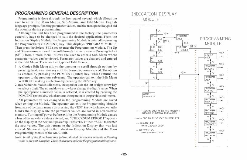
PROGRAMMING GENERAL DESCRIPTIONProgramming is done through the front panel keypad, which allows the
user to enter into Main Menus, Sub-Menus, and Edit Menus. Englishlanguage prompts, flashing parameter values, and the front panel keypad aidthe operator during programming.
Although the unit has been programmed at the factory, the parametersgenerally have to be changed to suit the desired application. From theIndication Display Module, the Programming Module is entered by pressingthe Program/Enter (PGM/ENT) key. This displays “PROGRAM MODE”.Then press the Select (SEL) key to enter the Programming Module. The Upand Down arrows are used to scroll through the main menus. Pressing Select(SEL) from a main menu, allows the user to enter a Sub-Menu whereparameter values can be viewed. Parameter values are changed and enteredin the Edit Menu. There are two types of Edit Menus:
1. A Choice Edit Menu allows the operator to scroll through options bypressing the down arrow key until the desired option is viewed. The optionis entered by pressing the PGM/ENT (enter) key, which returns theoperator to the previous sub-menu. The operator can exit the Edit MenuWITHOUT making a selection by pressing the <ESC key.
2. In a Numerical Value Edit Menu, the operator uses the left or right arrow keyto select a digit. The up and down arrow keys change the digit’s value. Whenthe appropriate numerical value is selected, it is entered by pressing thePGM/ENT (enter) key, which returns the operator to the previous sub-menu.
All parameter values changed in the Programming Module are savedwhen exiting the Module. The operator can exit the Programming Modulefrom any of the main menus by pressing the <ESC key, which momentarilyblanks the display while the parameter values are saved in non-volatilememory. Turning off power before exiting the Programming Module causesa loss of the new data values entered, and “CHECKSUM ERROR 1” appearson the display at the next unit power up. Press “ENT” then “SEL” to reenterthe new values. The unit returns to the Indication Display that was lastviewed. Shown at right is the Indication Display Module and the MainProgramming Menus of the MDC unit.
Note: In all of the flowcharts that follow, slanted characters indicate a flashingvalue in the unit’s display. These characters indicate the programmable options.
-12-

USER SETPOINTS MODULEThe User Setpoints Module is accessed
from any of the Indication Displays, orfrom any of the main menus in theProgramming Module (except OperatingMode Menu), by pressing the SET key.
Pressing “SET” once enters theSetpoint Scroll Menu. In this menu, thecurrent speed or ratio setpoint may beincremented or decremented using the Upand Down arrow keys. The top line of thedisplay shows the current setpoint valueand the bottom line shows actual speed indisplay units.
Pressing “SET” a second time enters theUser Setpoints Menu. The top line showsthe Setpoint description and the bottomline shows the Setpoint value. The up anddown arrow keys may be used to scrollthrough the loop. Pressing the SEL keyallows the value to be changed in a ValueEdit Menu. Press ESC to exit the UserSetpoints Module.
The following flowchart shows only theUser Setpoints portion:
-13-
� Note: These maximums are
additionally limited by unit
scaling. See individual
descriptions for details.
USER SETPOINTS IN MASTER MODESpeed Setpoint 1 (S1)
Speed Setpoint 1 is one of two user selectable speeds used in “RUN” mode.The speed value is entered in display units (user units) as defined in theProgram Scaling Menu. The value ranges from 0 to 99999, provided theDisplay Unit Maximum set in Program Scaling is 99999. Otherwise, the speedvalue is limited to the Display Unit Maximum. If a value greater than or equal tothe Display Unit Maximum is entered, the message “MAX RPM LIMIT”flashes on the display and the maximum speed is automatically entered.
Speed Setpoint 2 (S2)Speed Setpoint 2 is the second user selectable speed used in “RUN” mode.
A User Input must be configured to allow selection of Setpoint 1 or 2 for useas the current speed setpoint. If no User Input is configured for setpointselection (SPT SEL), the factory default setting is Speed Setpoint 1 (seeProgram User Menu for details).
Ramp Rate 1 (RAMP 1)Ramp Rate 1 is used for acceleration and deceleration between “RUN” and
“STOP” modes or between speed setpoints. The ramp rate value is entered indisplay units/second. For example, if the Display Units are RPM, then theramp rate is RPM/SEC. The value ranges from 1 to 99999, provided that it isnot greater than or equal to the internal limit of 20,000 feedback pulses persecond. If this occurs, the message “MAX RAMP RATE” flashes on thedisplay and the maximum ramp rate is automatically entered. A “0” valuemay be entered, which automatically selects the maximum ramp rate.
Ramp Rate 2 (RAMP 2)Ramp Rate 2 is the second user selectable ramp rate. A User Input must be
configured to allow selection of RAMP 1 or 2 for use as the current ramp rate.If no User Input is configured for ramp selection (RAMP SEL), the factorydefault setting is RAMP 1 (see Program User Menu for details).
Jog Speed (JOG SPD)The Jog Speed setpoint is used in JOG mode (See JOG under Dedicated
Control Input Functions for details). The value entered is in display units withthe same range and limitations as Speed Setpoint 1.
Jog Ramp Rate (JOG RAMP)The Jog Ramp Rate applies when entering JOG mode and accelerating to
the Jog Speed. The value entered is in display units/sec. with the same rangeand limitations as Ramp Rate 1.
Alarm 1 (AL-1)The Alarm 1 value is entered in display units. This value affects the Alarm
1 output. The alarm type is programmable and may be: High Speed, LowSpeed, Deviation, or Zero Speed. A Zero Speed alarm has no Value EditMenu. The value range for an alarm setpoint may be 0 to 99999, provided thatit is not greater than the internal equivalent of 20971 feedback pulses persecond. If this occurs, the message “SCALING LIMIT” is flashed on thedisplay and the maximum value is automatically entered.
Alarm 2 (AL-2)The Alarm 2 value affects the Alarm 2 output. It is programmable and has
the same range and limitations as Alarm 1.
Error Gain (GAIN)The Error Gain affects the closed loop response to a deviation from the
speed setpoint. It has a value range of 0 to 99. A “0” entry eliminatescorrection for speed error. A “99” entry provides maximum correction forspeed error and is the factory default setting. If instability or oscillation inmotor speed occurs, this value should be reduced.
-14-

USER SETPOINTS IN FOLLOWER MODEThe setpoints listed below are independent FOLLOWER mode setpoints.
They are retained separately from the MASTER mode setpoints innon-volatile memory. Jog, Alarm, and Gain values are shared parametersused by both MASTER and FOLLOWER modes.
Ratio Setpoint 1 (S1)Ratio Setpoint 1 is one of two user selectable ratio setpoints used in “RUN”
mode. The ratio value entered sets the follower motor’s speed as a ratio to thelead signal input. The range is 0.0000 to 1.9999.
Follower Speed (RPM) = Ratio Setpoint x Unity Ratio x Lead Speed (RPM)
A ratio setpoint of 1.0000 implies that the follower motor will run at thesame speed as the lead motor if the Unity Ratio is 1.0. The unity ratio isdetermined by the values entered for MAX RPM FB and MAX RPM LD in theProgram Scaling Menu.
Ratio Setpoint 2 (S2)Ratio Setpoint 2 is the second user selectable Ratio setpoint. A User Input
must be configured to allow selection of Setpoint 1 or 2 for use as the currentRatio setpoint. If no User Input is configured for setpoint selection (SPTSEL), the factory default setting is Setpoint 1. (See Program User Menu).
Ramp Rate 1 (RAMP 1)Ramp Rate 1 is one of two user selectable ramp rates used for acceleration
and deceleration between “RUN” and “STOP” modes or between ratiosetpoints. The ramp rate value is entered in ratio units/second. The valueranges from 0.0001 to 1.9999 ratio units/sec. A value of 0.0000 may beentered to select the maximum ramp rate of 1.9999. This causes the message“MAX RAMP RATE” to be flashed on the display and the maximum ramprate of 1.9999 to be automatically entered.
Ramp Rate 2 (RAMP 2)Ramp Rate 2 is the second user selectable ramp rate. A User Input must be
configured to allow selection of RAMP 1 or 2 for use as the current ramp rate.If no User Input is configured for ramp selection (RAMP SEL), the factorydefault setting is RAMP 1 (see Program User Menu).
-15-
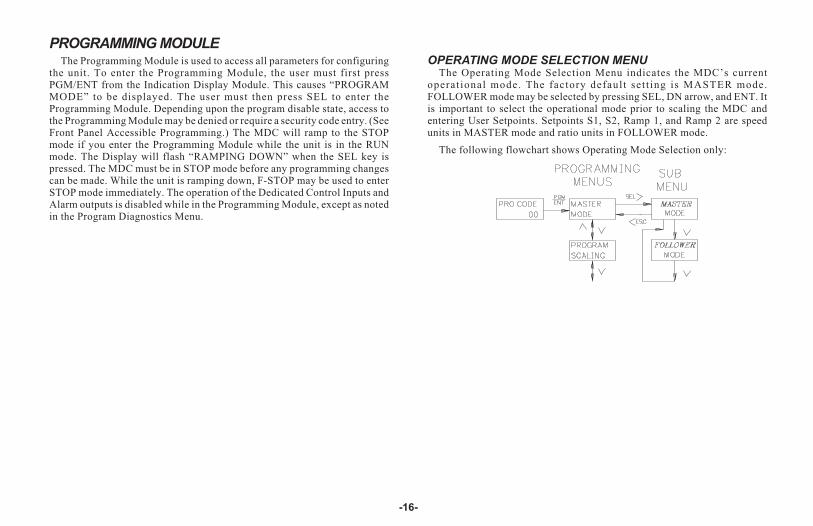
PROGRAMMING MODULEThe Programming Module is used to access all parameters for configuring
the unit. To enter the Programming Module, the user must first pressPGM/ENT from the Indication Display Module. This causes “PROGRAMMODE” to be displayed. The user must then press SEL to enter theProgramming Module. Depending upon the program disable state, access tothe Programming Module may be denied or require a security code entry. (SeeFront Panel Accessible Programming.) The MDC will ramp to the STOPmode if you enter the Programming Module while the unit is in the RUNmode. The Display will flash “RAMPING DOWN” when the SEL key ispressed. The MDC must be in STOP mode before any programming changescan be made. While the unit is ramping down, F-STOP may be used to enterSTOP mode immediately. The operation of the Dedicated Control Inputs andAlarm outputs is disabled while in the Programming Module, except as notedin the Program Diagnostics Menu.
OPERATING MODE SELECTION MENUThe Operating Mode Selection Menu indicates the MDC’s current
operat ional mode. The factory default set t ing is MASTER mode.FOLLOWER mode may be selected by pressing SEL, DN arrow, and ENT. Itis important to select the operational mode prior to scaling the MDC andentering User Setpoints. Setpoints S1, S2, Ramp 1, and Ramp 2 are speedunits in MASTER mode and ratio units in FOLLOWER mode.
The following flowchart shows Operating Mode Selection only:
-16-

PROGRAM SCALING MENUThe Program Scaling Menu is used to scale the MDC to the specific motor
(or shaft) feedback transducer output. This Menu also scales the speed inRPM to the Display units which are seen on the display and used for speedsetpoint entry.
The following flowchart shows only the Scaling portion:
PPR FB (Pulses Per Revolution- Feedback)Enter the number of pulses per revolution generated by the feedback
transducer. The value for PPR FB ranges from 1 to 59999.
MAX RPM FB (Maximum RPM- Feedback)Enter the maximum RPM for the feedback input transducer. This is the
maximum normal operating speed (in RPM) of the motor (or shaft) which isgenerating the feedback signal. The value ranges from 1 to 59999.
Note: If the Maximum Equivalent Frequency exceeds 20971 Hz, “OVFLW”flashes over the numeric value and a new entry is required.
Maximum Equivalent Frequency = PPR x MAX RPM60
DSP DP (Display Decimal Point)Select the display decimal point position. Press SEL and use the DN arrow
key to select the decimal point position. The decimal point position is a placeholder only and does not affect scaling. The available options are:
00.00.000.0000.00000.00000
DSP UNIT (Maximum Display Units)Enter the value to be displayed when the motor (or shaft) is running at the
speed entered for MAX RPM FB. This value is also the maximum allowablespeed setpoint. The value ranges from 1 to 99999.
-17-
PROGRAM SCALING MENU (Cont’d)
ADDITIONAL SCALE FACTORS IN FOLLOWER MODE
PPR LD (Pulses Per Revolution- Lead)Enter the number of pulses per revolution generated by the lead transducer.
If an artificial frequency source is used, set PPR LD to 60. This SETS 1 RPM= 1 Hz. Max RPM Lead can then be entered in Hz. The value for PPR LDranges from 1 to 59999.
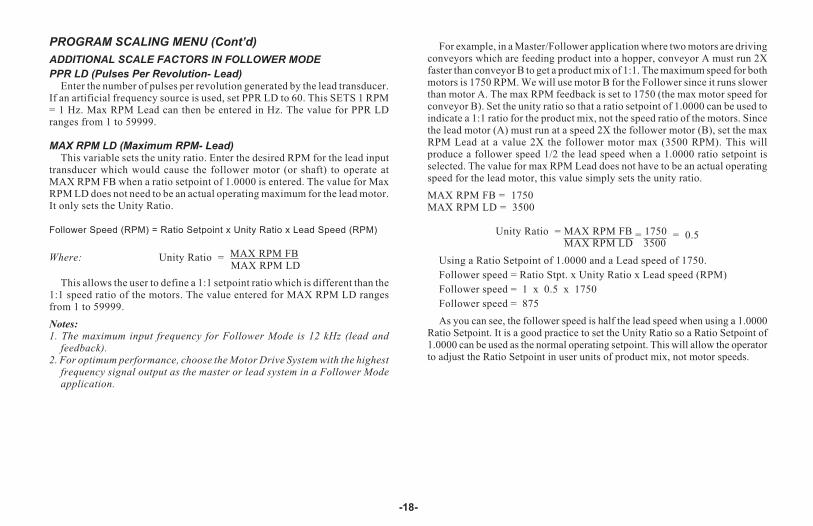
MAX RPM LD (Maximum RPM- Lead)This variable sets the unity ratio. Enter the desired RPM for the lead input
transducer which would cause the follower motor (or shaft) to operate atMAX RPM FB when a ratio setpoint of 1.0000 is entered. The value for MaxRPM LD does not need to be an actual operating maximum for the lead motor.It only sets the Unity Ratio.
Follower Speed (RPM) = Ratio Setpoint x Unity Ratio x Lead Speed (RPM)
Where: Unity Ratio = MAX RPM FBMAX RPM LD
This allows the user to define a 1:1 setpoint ratio which is different than the1:1 speed ratio of the motors. The value entered for MAX RPM LD rangesfrom 1 to 59999.
Notes:
1. The maximum input frequency for Follower Mode is 12 kHz (lead andfeedback).
2. For optimum performance, choose the Motor Drive System with the highestfrequency signal output as the master or lead system in a Follower Modeapplication.
For example, in a Master/Follower application where two motors are drivingconveyors which are feeding product into a hopper, conveyor A must run 2Xfaster than conveyor B to get a product mix of 1:1. The maximum speed for bothmotors is 1750 RPM. We will use motor B for the Follower since it runs slowerthan motor A. The max RPM feedback is set to 1750 (the max motor speed forconveyor B). Set the unity ratio so that a ratio setpoint of 1.0000 can be used toindicate a 1:1 ratio for the product mix, not the speed ratio of the motors. Sincethe lead motor (A) must run at a speed 2X the follower motor (B), set the maxRPM Lead at a value 2X the follower motor max (3500 RPM). This willproduce a follower speed 1/2 the lead speed when a 1.0000 ratio setpoint isselected. The value for max RPM Lead does not have to be an actual operatingspeed for the lead motor, this value simply sets the unity ratio.
MAX RPM FB = 1750MAX RPM LD = 3500
Unity Ratio = MAX RPM FB = 1750 = 0.5MAX RPM LD 3500
Using a Ratio Setpoint of 1.0000 and a Lead speed of 1750.
Follower speed = Ratio Stpt. x Unity Ratio x Lead speed (RPM)
Follower speed = 1 x 0.5 x 1750
Follower speed = 875
As you can see, the follower speed is half the lead speed when using a 1.0000Ratio Setpoint. It is a good practice to set the Unity Ratio so a Ratio Setpoint of1.0000 can be used as the normal operating setpoint. This will allow the operatorto adjust the Ratio Setpoint in user units of product mix, not motor speeds.
-18-
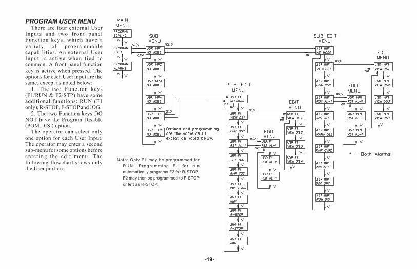
PROGRAM USER MENUThere are four external User
Inputs and two front panelFunction keys, which have avariety of programmablecapabilities. An external UserInput is act ive when tied tocommon. A front panel functionkey is active when pressed. Theoptions for each User input are thesame, except as noted below:
1. The two Function keys(F1/RUN & F2/STP) have someadditional functions: RUN (F1only), R-STOP, F-STOP and JOG.
2. The two Function keys DONOT have the Program Disable(PGM.DIS.) option.
The operator can select onlyone option for each User Input.The operator may enter a secondsub-menu for some options beforeentering the edit menu. Thefollowing flowchart shows onlythe User portion:
-19-
Note: Only F1 may be programmed for
RUN. Programming F1 fo r run
automatically programs F2 for R-STOP.
F2 may then be programmed to F-STOP
or left as R-STOP.

PROGRAM USER MENU (Cont’d)NO MODE
If a User Input terminal or a Function key is activated, it will be ignored.
VIEW DISPLAY (VIEW DSn)In the Indication Display Module, the unit advances to the Indication
Display selected, when the User Input is activated. In the User SetpointsModule or Programming Module, the unit advances to the selected displayupon exiting that Module. DS1 selects display 1, DS2 display 2, DS3 display3, and DS4 display 4. If an input is momentary the display is selected, but canbe changed by use of the up or down arrow keys, or another User Input. If aninput is maintained the display cannot be advanced using the UP and DNarrow keys on the keypad. If more than one User Input is used for this option,the priority order from highest to lowest is F2, F1, USR INP4, USR INP3,USR INP2, and USR INP1. The items viewed on the display are determinedby what is selected in the Program Displays Menu.
CHANGE DISPLAY (CHG DSP)In the Indication Display Module, when a User Input is activated, the
Indication Display advances to the next Indication Display, this is a momentaryaction. If the operator is in the User Setpoint Module or the ProgrammingModule, the unit advances to the next display upon exiting that Module.
RESET ALARM 1 OUTPUT (RST AL-1)The operator can select to have Alarm Output 1, 2, or � (both) reset. If the
output is active, it resets to its inactive state when the User Input or functionkey is activated. This may be a momentary or maintained action. Amomentary action resets the alarm but it becomes active again within 10 msecif the alarm trigger condition still exists. A maintained action keeps the alarmreset regardless of the trigger condition.
Note: The Inactive state of an output can be ON or OFF depending on what isprogrammed in the Program Alarms Menu.
SETPOINT SELECT/TOGGLE (SPT SEL/TOG)ONLY ONE USER INPUT SHOULD BE PROGRAMMED FOR SPT
SEL/TOG. If more than one is programmed, the highest priority input isrecognized and all of the others are ignored. The priority order from highest tolowest is USR INP4, USR INP3, USR INP2, USR INP1, F1/F2.
SelectThe MDC uses S1 (setpoint 1) for its factory default speed or ratio setpoint.
If the User Input is made active, the MDC ramps to S2 at the current ramp rate.Making the input inactive causes the unit to ramp to S1. This is a maintainedsetpoint select for User Inputs 1 through 4.
ToggleFor F1 or F2, this is a momentary action causing a setpoint toggle between
S1 and S2.
RAMP SELECT/TOGGLE (RAMP SEL/TOG)ONLY ONE USER INPUT SHOULD BE PROGRAMMED FOR RAMP
SEL/TOG. If more than one is programmed, the highest priority input isrecognized and all of the others are ignored. The priority order from highest tolowest is USR INP4, USR INP3, USR INP2, USR INP1, F1/F2.
SelectThe MDC uses R1 (ramp 1) for its factory default ramp rate for both
acceleration and deceleration. If the User Input is made active, the MDC usesR2. Making the input inactive causes the unit to use R1. This is a maintainedramp select for User inputs 1 through 4.
ToggleFor F1 or F2, this is a momentary action causing a ramp toggle between R1
and R2.
RAMP OVERRIDE (RAMP OVRD)Making this input active overrides the acceleration/deceleration ramp
routine causing the unit to jump to the ramp endpoint. This may be a setpointchange or STOP condition. A momentary action overrides the current ramp inprocess. A maintained action overrides the current ramp in process and allfuture ramps.
Caution: Significant overshoot of the speed setpoint can occur with this feature.
-20-

SETPOINT INCREMENT (INC SPT)Only an external User Input can be used for this option. The currently
active speed or ratio setpoint is incremented when the User Input is madeactive. If the input remains active for more than 5 display unit increments, thescroll rate will progressively increase.
SETPOINT DECREMENT (DEC SPT)Only an external User Input can be used for this option. The currently
active speed or ratio setpoint is decremented when the User Input is madeactive. If the input remains active for more than 5 display unit increments, thescroll rate will progressively increase.
PROGRAM DISABLE (PGM.DIS.)Only an external User Input can be used for this option. When used with the
Program Disable DIP switch, this option can limit operator access toprogrammable parameters (see Front Panel Accessible Programming WithProgram Disable section). The program disable is maintained.
Additional Options Available For F1 & F2 Keys
RUNActivation of a function key selected for RUN causes the MDC to
accelerate the motor from STOP mode to the current speed setpoint using thecurrent ramp rate.
RAMP STOPActivation of a function key selected for R-STOP causes the MDC to
decelerate the motor from its current speed to STOP mode using the currentramp rate.
FAST STOPActivation of a function key selected for F-STOP causes the MDC to
execute a fast stop, taking the analog Drive Output signal immediately to zerovolts. Motor deceleration is limited only by the motor drive system. This is anemergency stop function. The Drive Enable Output goes immediately to itsinactive state and may be used to engage braking or remove power from themotor via an external relay.
JOGThe jog function only operates from the STOP mode. Pressing and holding a
function key selected for JOG causes the MDC to accelerate the motor to thejog speed setpoint using the jog ramp rate. The motor remains at the jog speeduntil the function key is released, at which point the MDC executes an F-STOP.
-21-
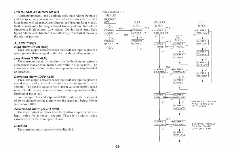
PROGRAM ALARMS MENUAlarm parameters 1 and 2 activate solid state Alarm Outputs 1
and 2 respectively. A manual reset, which requires the use of aUser Input, will reset an Alarm Output (see Program User Menu).Both alarms may be programmed for any of the five alarmfunctions: High Alarm, Low Alarm, Deviation Alarm, ZeroSpeed Alarm, and Disabled. The following flowchart shows onlythe Alarms portion:
ALARM TYPESHigh Alarm (HIGH ALM)
The alarm output activates when the feedback input registers aspeed greater than or equal to the alarm value in display units.
Low Alarm (LOW ALM)The alarm output activates when the feedback input registers
a speed less than or equal to the alarm value in display units. Thealarm may be active or inactive in stop mode (see Stop Enabledor Disabled).
Deviation Alarm (DEV ALM)The alarm output activates when the feedback input registers a
speed outside of a � band around the current speed or ratiosetpoint. The band is equal to the � alarm value in display speedunits. The alarm may be active or inactive in stop mode (see StopEnabled or Disabled).
For Example: A speed setpoint of 1000, with an alarm setpointof 10 would activate the alarm when the speed fell below 990 orwent above 1010.
Zero Speed Alarm (ZERO SPD)The alarm output activates when the feedback input receives no
input pulse for at least 1 second. There is no alarm valueassociated with the Zero Speed Alarm.
DisabledThe alarm output is inactive when disabled.
-22-
PhaseThe positive (+) phase of an output indicates that when the alarm becomes
active, the output turns on. When the output is reset it is turned off.The negative (-) phase of an output indicates that when the alarm becomes
active, the output turns off. The reset condition of the output is the on state.
Boundary or LatchedAn alarm programmed for Boundary Output becomes active as determined
by the alarm type (High, Low, Deviation, or Zero Speed). The output staysactive as long as this alarm trigger condition exists, after which the outputreturns to its inactive state. A maintained reset on a User Input programmedfor Reset Alarm causes the alarm to stay in its inactive state at all times (seeProgram User Menu).
An alarm programmed for Latched Output becomes active as determinedby the alarm type (High, Low, Deviation, or Zero Speed). The output staysactive until it is manually reset by a User Input selected for that function. Amomentary reset causes the output to return to its inactive state provided thatthe condition causing the alarm no longer exists. A maintained reset on a UserInput programmed for Reset Alarm causes the alarm to stay in its inactivestate at all times (see Program User Menu).
Normal or Fast UpdateThe Normal update for the alarm outputs is once each second. This is the
same as the Speed or Ratio display update. The calculation to check for thealarm condition is made from an average value of feedback measurementstaken over a 1 second period.
The Fast alarm update occurs at an interval less than or equal to 40 msec.The calculation to check for the alarm condition is made from a singlefeedback and/or lead frequency measurement. Since no average is made,peaks caused by pulse encoder non-linearity (such as differences in thespacing of teeth on a gear or an unbalanced shaft) can cause the alarm totrigger early. THE FAST UPDATE SHOULD ONLY BE USED WHENFAST RESPONSE IS NECESSARY.
Stop Enabled or DisabledThis is an option that pertains only to the Low alarm and Deviation alarm. It
refers to the alarm function when the MDC is in STOP mode or ramping to orfrom STOP mode. When the alarm is Stop Enabled, the alarm functionsnormally in stop mode. A low alarm would always be on since zero speed isalways less than or equal to the speed setpoint.
When the alarm is programmed to be Stop Disabled, the alarm is alwaysinactive in stop mode and when ramping to or from stop mode. The alarm canonly become active after the speed setpoint value has been attained in MasterMode, or when the ramp up to the setpoint ratio is complete in Follower Mode.
-23-
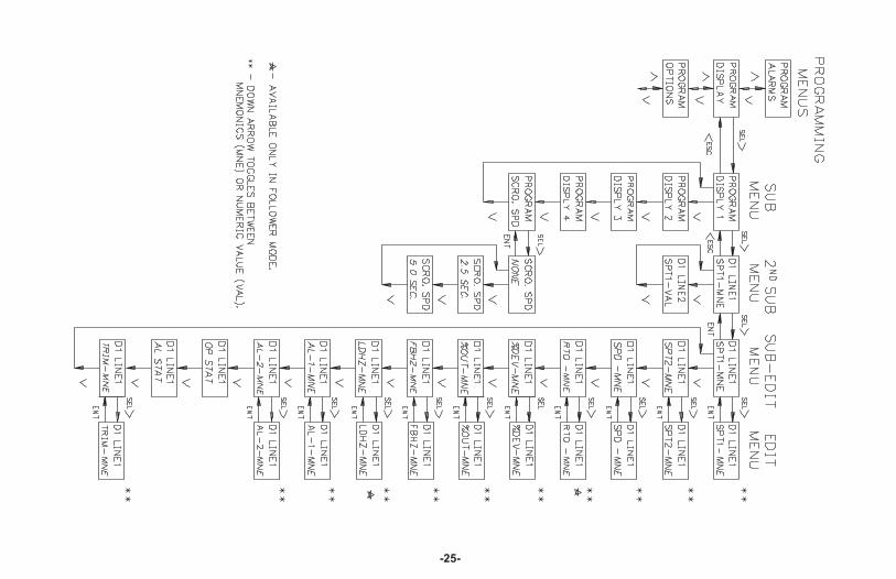
PROGRAM DISPLAYS MENUEach line of each Indication Display can be programmed individually to
show mnemonics or a numeric value for: Speed/Ratio Setpoint 1 or 2, Speed,Ratio, % Deviation, % Output, Feedback Frequency, Lead Frequency, Alarm1 or 2 setpoint and Trim. Or, each line may be programmed to one of the twostatus displays: Operating Status or Alarm Output status. If an IndicationDisplay is to show two different numeric values, one for each line, there willbe a single or dual character mnemonic to the left of the numeric value. Thiswill also be true if one line is programmed for operating status or alarm outputstatus. The flowchart on the following page shows only the Display portion:
DISPLAYS 1 TO 4Each line of each display has the same programmable options. MNE is the
abbreviation for Mnemonics and VAL is for Value. The following list showsthe single or dual character mnemonics that will be displayed when VAL isselected and the full mnemonic when MNE is selected:
VAL MNE DESCRIPTION
S1 99999 SETPT. 1 Speed or ratio setpoint 1
S2 99999 SETPT. 2 Speed or ratio setpoint 2
Sp 99999 SPEED Actual speed in user display units (feedback)
R 1.999 RATIO Actual feedback to lead input speed ratio(follower mode)
%D 100.0 % DEV. % deviation of actual speed from target speed
%O 100.0 % OUTPUT Analog drive output- % of full scale voltage
FB 20971 FB. FREQ Feedback frequency in pulses/sec (Hz.)
LD 12000 LD. FREQ Lead frequency in pulses/sec (Hz.)
A1 99999 ALARM 1 Alarm 1 setpoint
A2 99999 ALARM 2 Alarm 2 setpoint
Tr 4095 TRIM Error correction in bits (-4095 to +4095)(See Isolated Drive Output Calibration section)
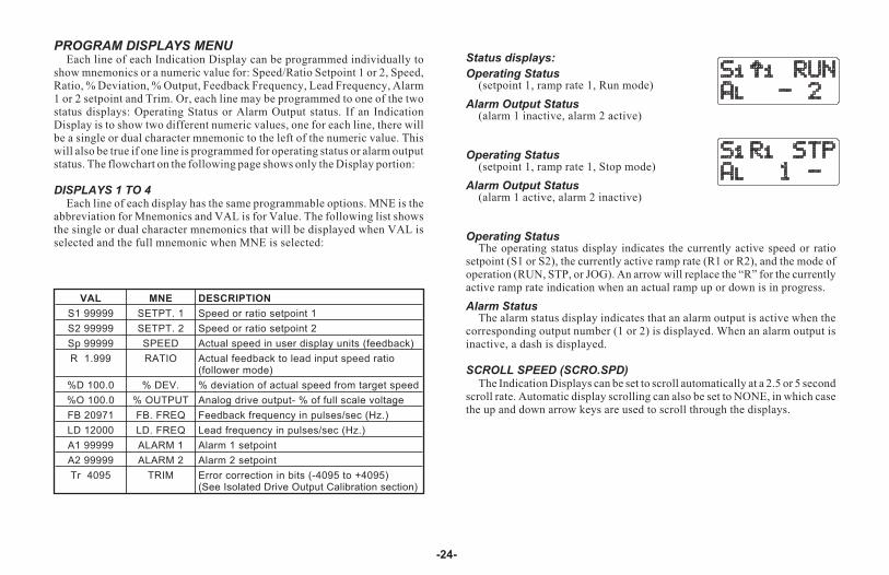
Status displays:
Operating Status(setpoint 1, ramp rate 1, Run mode)
Alarm Output Status(alarm 1 inactive, alarm 2 active)
Operating Status(setpoint 1, ramp rate 1, Stop mode)
Alarm Output Status(alarm 1 active, alarm 2 inactive)
Operating StatusThe operating status display indicates the currently active speed or ratio
setpoint (S1 or S2), the currently active ramp rate (R1 or R2), and the mode ofoperation (RUN, STP, or JOG). An arrow will replace the “R” for the currentlyactive ramp rate indication when an actual ramp up or down is in progress.
Alarm StatusThe alarm status display indicates that an alarm output is active when the
corresponding output number (1 or 2) is displayed. When an alarm output isinactive, a dash is displayed.
SCROLL SPEED (SCRO.SPD)The Indication Displays can be set to scroll automatically at a 2.5 or 5 second
scroll rate. Automatic display scrolling can also be set to NONE, in which casethe up and down arrow keys are used to scroll through the displays.
-24-
-25-
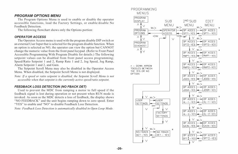
PROGRAM OPTIONS MENUThe Program Options Menu is used to enable or disable the operator
accessible functions, load the Factory Settings, or enable/disable NoFeedback Detection.
The following flowchart shows only the Options portion:
OPERATOR ACCESSThe Operator Access menu is used with the program disable DIP switch or
an external User Input that is selected for the program disable function. Whenan option is selected as NO, the operator can view the option but CANNOTchange the numeric value from the front panel keypad. (Refer to Front PanelAccessible Programming With Program Disable for details.) The followingsetpoint values can be disabled from front panel access programming;Speed/Ratio Setpoint 1 and 2, Ramp Rate 1 and 2, Jog Speed, Jog Ramp,Alarm Setpoint 1 and 2, and Gain.
The Setpoint Scroll Menu may also be disabled in the Operator AccessMenu. When disabled, the Setpoint Scroll Menu is not displayed.
Note: If a speed or ratio setpoint is disabled, the Setpoint Scroll Menu is notaccessible when that setpoint is the currently active speed/ratio setpoint.
FEEDBACK LOSS DETECTION (NO FBACK DET)Used to prevent the MDC from ramping a motor to full speed if the
feedback signal is lost during operation or not present when RUN mode isinvoked. As soon as the MDC detects a loss of feedback, the display shows“NO FEEDBACK” and the unit begins ramping down to zero speed. Enter“YES” to enable and “NO” to disable Feedback Loss Detection.
Note: Feedback Loss Detection is automatically disabled in Open Loop Mode.
-26-
FACTORY SETTINGS
MASTER MODE: FOLLOWER MODE:USER SETPOINTS: USER SETPOINTS:
S1 500 S1 1.0000
S2 1000 S2 0.5000
R1 100 R1 0.1000
R2 200 R2 0.2000
DISPLAY 1 DISPLAY 1LINE 1 SPD-MNE LINE 1 SPD-MNELINE 2 SPD-VAL LINE 2 SPD-VAL
DISPLAY 2 DISPLAY 2LINE 1 OP STAT LINE 1 OP-STATLINE 2 SPD- VAL LINE 2 SPD-VAL
DISPLAY 3 DISPLAY 3LINE 1 AL STAT LINE 1 LDHZ-VALLINE 2 SPD -VAL LINE 2 FBHZ-VAL
DISPLAY 4 DISPLAY 4LINE 1 TRIM-VAL LINE 1 TRIM-VALLINE 2 SPD -VAL LINE 2 SPD-VAL
SCALING:PPR LD 60MAX RPM LD 1750
-27-
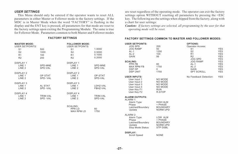
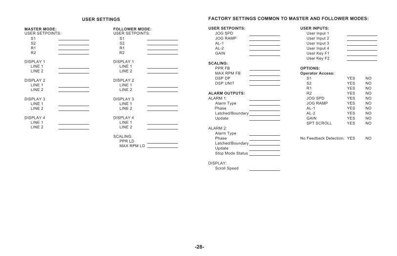
USER SETTINGSThis Menu should only be entered if the operator wants to reset ALL
parameters in either Master or Follower mode to the factory settings. If theMDC is in Master Mode when the word “FACTORY” is flashing in thedisplay and the ENT key is pressed, all parameters for that mode are reset tothe factory settings upon exiting the Programming Module. The same is truefor Follower Mode. Parameters common to both Master and Follower modes
are reset regardless of the operating mode. The operator can exit the factorysettings option WITHOUT resetting all parameters by pressing the <ESCkey. The following are the settings when shipped from the factory, along witha chart for user settings:Caution: If factory settings are selected, all programming by the user for that
operating mode will be reset.
FACTORY SETTINGS COMMON TO MASTER AND FOLLOWER MODES:
USER SETPOINTS: OPTIONS:JOG SPD 200 Operator Access:JOG RAMP 50 S1 YESAL-1 1200 S2 YESAL-2 100 R1 YESGAIN 99 R2 YES
JOG SPD YESSCALING: JOG RAMP YES
PPR FB 60 AL-1 YESMAX RPM FB 1750 AL-2 YESDSP DP 0 GAIN YESDSP UNIT 1750 SPT SCROLL YES
USER INPUTS: No Feedback Detection: YESUser Input 1 NO MODEUser Input 2 NO MODEUser Input 3 NO MODEUser Input 4 NO MODEUser Key F1 RUNUser Key F2 R-STOP
ALARM OUTPUTS:ALARM 1:
Alarm Type HIGH ALMPhase + PHASELatched/Boundary BOUNDARYUpdate NORM UPD
ALARM 2:Alarm Type LOW ALMPhase + PHASELatched/Boundary BOUNDARYUpdate NORM UPDStop Mode Status STP DSBL
DISPLAY:Scroll Speed NONE
-28-
USER SETTINGS
MASTER MODE: FOLLOWER MODE:USER SETPOINTS: USER SETPOINTS:
S1 S1
S2 S2
R1 R1
R2 R2
DISPLAY 1 DISPLAY 1
LINE 1 LINE 1
LINE 2 LINE 2
DISPLAY 2 DISPLAY 2
LINE 1 LINE 1
LINE 2 LINE 2
DISPLAY 3 DISPLAY 3
LINE 1 LINE 1
LINE 2 LINE 2
DISPLAY 4 DISPLAY 4
LINE 1 LINE 1
LINE 2 LINE 2
SCALING:
PPR LD
MAX RPM LD
FACTORY SETTINGS COMMON TO MASTER AND FOLLOWER MODES:
USER SETPOINTS: USER INPUTS:
JOG SPD User Input 1
JOG RAMP User Input 2
AL-1 User Input 3
AL-2 User Input 4
GAIN User Key F1
User Key F2
SCALING:
PPR FB OPTIONS:
MAX RPM FB Operator Access:
DSP DP S1 YES NO
DSP UNIT S2 YES NO
R1 YES NO
ALARM OUTPUTS: R2 YES NO
ALARM 1: JOG SPD YES NO
Alarm Type JOG RAMP YES NO
Phase AL-1 YES NO
Latched/Boundary AL-2 YES NO
Update GAIN YES NO
SPT SCROLL YES NO
ALARM 2:
Alarm Type
Phase No Feedback Detection: YES NO
Latched/Boundary
Update
Stop Mode Status
DISPLAY:
Scroll Speed

PROGRAM DIAGNOSTICS MENUThis Menu allows testing of the various MDC inputs and outputs. It is
especially useful after unit installation to independently test the operation ofexternal switches, relays, the feedback transducer, and the motor drive system.
The following flowchart shows only the Diagnostics portion:
TEST INPUTSThe MDC displays an alphanumeric character to indicate a Dedicated
Function Input or a User Input is active. This allows the user to check switchoperation and wiring connections to the Inputs. It is made up of two sections.READ INP (read inputs) shows the state of the dedicated control inputs.READ USR (read user) shows the state of the programmable User Inputs. A“--” displayed on line 2 indicates that the input is inactive and analphanumeric character indicates that the input is active. All of the inputsexcept F-STOP and R-STOP are active when pulled to common. F-STOP andR-STOP are active when left floating.
R=RUN, S=RAMP STOP, F=FSTOP, J=JOG, O=OPEN LOOP
READ INP READ INP
- - - - - RSFJO
(all inactive) (all active)
READ USR READ USR
- - - - 1234
(all inactive) (all active)
The User Input is indicated by the number shown.
-29-
PROGRAM DIAGNOSTICS MENU (Cont’d)TEST ALARMS
The up and down arrow keys are used to select an alarm output and set it tothe active or inactive state. This allows the user to check the operation ofdevices wired to the alarm outputs and the wiring connections. Please notethat the active state is defined by the PHASE programming in the ProgramAlarms Menu.
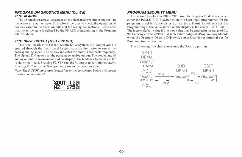
TEST DRIVE OUTPUT (TEST DRV OUT)This function allows the user to test the Drive System. A % Output value is
entered through the front panel keypad causing the motor to run at thecorresponding speed. The display indicates the motor’s feedback frequency.The Up and DN arrows set the percentage analog output. The percentage ofanalog output is shown on line 1 of the display. The feedback frequency in Hzis shown on line 2. Pressing F2/STP sets the % output to zero immediately.Pressing ESC zeros the % output and exits to the previous menu.
Note: The F-STOP input must be held low or tied to common before a % outputvalue can be entered.
PROGRAM SECURITY MENUThis is used to select the PRO.CODE used for Program Mode access when
either the PGM.DIS. DIP switch is on or a User Input programmed for theprogram disable funct ion is act ive (see Front Panel AccessibleProgramming). The value shown on the display is the current PRO. CODE.The factory default value is 0. A new value may be entered in the range of 0 to98. Entering a value of 99 will disable future entry into Programming Modulewhen the Program Disable DIP switch or a User Input terminal set forProgram Disable is active.
The following flowchart shows only the Security portion:
-30-
-31-
INSTALLATION & CONNECTIONSInstallation Environment
Before installing the MDC into the panel, the user should first becomefamiliar with the unit. Also, it may be desirable to program the unit and set theappropriate DIP switches for the application. When programming iscomplete, all parameters are saved in non-volatile memory. The ProgramDisable DIP switch used with an external User Input, set for the programdisable function, provides various levels of security to prevent accidental or
unauthorized programming changes. The MDC should be installed in alocation that does NOT exceed the maximum operating temperature andprovides good air circulation. Placing the unit near devices that generateexcessive heat should be avoided.
The bezel should be cleaned only with a soft cloth and neutral soapproduct. Do NOT use solvents. Continuous exposure to direct sunlight mayaccelerate the aging process of the bezel.
Do not use tools of any kind (screwdrivers, pens, pencils, etc.) to operatethe keypad of the unit.
InstallationThe unit meets NEMA 4X/IP65 requirements for indoor use
when properly installed. The units are intended to be mounted intoan enclosed panel with a gasket to provide a watertight seal. Twomounting clips and screws are provided for easy installation.Consideration should be given to the thickness of the panel. Apanel that is too thin may distort and not provide a watertight seal.(Recommended minimum panel thickness is 1/8� [3.2 mm]). Therecommended clearance behind the panel for mounting clipinstallation is 3.0� (6.45 cm) H x 4.0� (10.16 cm) W.
After the panel cut-out is completed and deburred, carefullyapply the gasket to the panel.
DO NOT APPLY THE ADHESIVE SIDE OF THE
GASKET TO THE BEZEL.
Insert the unit into the panel as depicted in the drawing.Thread the screws into the clips until the pointed end justprotrudes through the other side. Install each mounting clip byinserting the case tabs of the clip into the holes located on eitherside of the bezel.
Then snap the rear end of the clip into the case and slide theclip towards the rear of the unit, locking it in place. Tighten thescrews evenly to apply uniform compression, thus providing awatertight seal.
Caution: Only minimum pressure is required to seal thepanel. Do NOT overtighten mounting screws.
EMC INSTALLATION GUIDELINESAlthough this unit is designed with a high degree of immunity to
ElectroMagnetic Interference (EMI), proper installation and wiring methodsmust be followed to ensure compatibility in each application. The type of theelectrical noise, source or coupling method into the unit may be different forvarious installations. It should be noted that the methods listed below may notbe necessary for every unit installation. In extremely high EMI environments,additional measures may be needed. The unit becomes more immune to EMIwith fewer I/O connections. Cable length, routing and shield termination arevery important and can mean the difference between a successful or atroublesome installation. Listed below are some EMC guidelines forsuccessful installation in an industrial environment.
1. Use shielded (screened) cables for all Signal and Control inputs andoutputs. The shield (screen) pigtail connection should be made as short aspossible. The connection point for the shield depends somewhat upon theapplication. Listed below are the recommended methods of connectingthe shield, in order of their effectiveness.
a. Connect the shield only at the panel where the unit is mounted to earthground (protective earth).
b. Connect the shield to earth ground at both ends of the cable, usuallywhen the noise source frequency is above 1 MHz.
c. Connect the shield to common of the unit and leave the other end of theshield unconnected and insulated from earth ground.
2. Never run Signal or Control cables in the same conduit or raceway withAC power lines, conductors feeding motors, solenoids, SCR controls, andheaters, etc. The cables should be run in metal conduit that is properlygrounded. This is especially useful in applications where cable runs arelong and portable two-way radios are used in close proximity or if theinstallation is near a commercial radio transmitter.
3. Signal or Control cables within an enclosure should be routed as far awayas possible from contactors, control relays, transformers, and other noisycomponents.
4. In extremely high EMI environments, the use of external EMI suppressiondevices, such as ferrite suppression cores, is effective. Install them onSignal and Control cables as close to the unit as possible. Loop the cablethrough the core several times or use multiple cores on each cable foradditional protection. Install line filters on the power input cable to theunit to suppress power line interference. Install them near the power entry
point of the enclosure. The following EMI suppression devices (orequivalent) are recommended:Ferrite Suppression Cores for signal and control cables:
Fair-Rite#0443167251 (RLC#FCOR0000)TDK # ZCAT3035-1330ASteward #28B2029-0A0
Line Filters for input power cables:Schaffner#FN610-1/07 (RLC#LFIL0000)Schaffner # FN670-1.8/07Corcom #1VB3Corcom #1VR3
Note: Reference manufacturers instructions when installing a line
filter.
5. Long cable runs are more susceptible to EMI pickup than short cable runs.Therefore, keep cable runs as short as possible.
6. Switching of inductive loads produces high EMI. Use of snubbers acrossinductive loads suppresses EMI.Snubbers:
RLC #SNUB0000
-32-
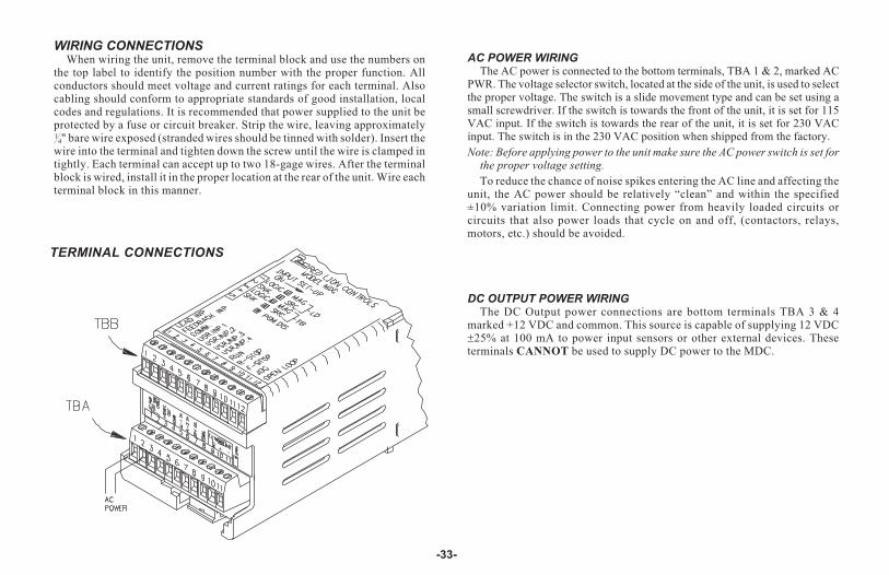
WIRING CONNECTIONSWhen wiring the unit, remove the terminal block and use the numbers on
the top label to identify the position number with the proper function. Allconductors should meet voltage and current ratings for each terminal. Alsocabling should conform to appropriate standards of good installation, localcodes and regulations. It is recommended that power supplied to the unit beprotected by a fuse or circuit breaker. Strip the wire, leaving approximately1
4" bare wire exposed (stranded wires should be tinned with solder). Insert thewire into the terminal and tighten down the screw until the wire is clamped intightly. Each terminal can accept up to two 18-gage wires. After the terminalblock is wired, install it in the proper location at the rear of the unit. Wire eachterminal block in this manner.
AC POWER WIRINGThe AC power is connected to the bottom terminals, TBA 1 & 2, marked AC
PWR. The voltage selector switch, located at the side of the unit, is used to selectthe proper voltage. The switch is a slide movement type and can be set using asmall screwdriver. If the switch is towards the front of the unit, it is set for 115VAC input. If the switch is towards the rear of the unit, it is set for 230 VACinput. The switch is in the 230 VAC position when shipped from the factory.
Note: Before applying power to the unit make sure the AC power switch is set forthe proper voltage setting.
To reduce the chance of noise spikes entering the AC line and affecting theunit, the AC power should be relatively “clean” and within the specified±10% variation limit. Connecting power from heavily loaded circuits orcircuits that also power loads that cycle on and off, (contactors, relays,motors, etc.) should be avoided.
DC OUTPUT POWER WIRINGThe DC Output power connections are bottom terminals TBA 3 & 4
marked +12 VDC and common. This source is capable of supplying 12 VDC�25% at 100 mA to power input sensors or other external devices. Theseterminals CANNOT be used to supply DC power to the MDC.
-33-
TERMINAL CONNECTIONS
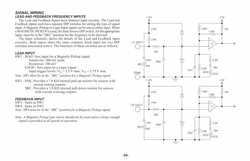
SIGNAL WIRINGLEAD AND FEEDBACK FREQUENCY INPUTS
The Lead and Feedback Inputs have identical input circuitry. The Lead andFeedback inputs each have separate DIP switches for setting the type of signalinput. A Magnetic Pickup or Logic Input signal can be sent to either input. Whena MAGNETIC PICKUP is used, the Sink/Source DIP switch, for the appropriateinput, must be in the “SRC” position for the frequency to be detected.
The Input schematic shows the details of the Lead and Feedback inputcircuitry. Both inputs share the same common. Each input has two DIPswitches associated with it. The functions of these switches are as follows:
LEAD INPUTSW1 - MAG: Sets input for a Magnetic Pickup signal.
Sensitivity: 200 mV peak;Hysteresis: 100 mV
LOGIC: Sets input for a Logic signal.Input trigger levels: VIL = 1.5 V max; VIH = 3.75 V min.
Note: SW2 Must be in the “SRC” position for a Magnetic Pickup signal.
SW2 - SNK: Provides a 7.8 K� internal pull-up resistor for sensors withcurrent sinking outputs.
SRC: Provides a 3.9 K� internal pull-down resistor for sensorswith current sourcing outputs.
FEEDBACK INPUTSW3 - Same as SW1SW4 - Same as SW2Note: SW4 must be in the “SRC” position for a Magnetic Pickup signal.
Note: A Magnetic Pickup type sensor should not be used unless a large enoughsignal is provided at all speeds of operation.
-34-

DEDICATED FUNCTION AND USER INPUTSRefer to the Terminal Connections drawing. TBA is the bottom terminal
block and TBB is the top terminal block.
RUN (TBB8): A momentary closure to common on theRUN input causes the MDC to accelerate the motor fromSTOP mode to the current speed setpoint using thecurrent ramp rate.- R-STOP (TBB-9) and F-STOP (TBB-10) must be held
low or tied to common (TBB-3).- MDC must be in the Indication Display or User Setpoints Module.- MDC may not be in JOG mode.
R-STOP (TBB9): A momentary open from common on theR-STOP input causes the MDC to decelerate the motorfrom its current speed to STOP mode using the currentramp rate.- MDC must be in RUN mode. R-STOP is inoperative in
JOG mode.
F-STOP (TBB10): A momentary open from common on theF-STOP input causes the MDC to execute a fast stop,taking the analog Drive Output signal immediately to zerovolts. The motor deceleration is limited only by the motordrive system. This is an emergency stop function. Thedrive Enable Output goes immediately to its inactive state and may be usedto engage braking or remove power from the motor via an external relay.- F-STOP overrides all other active function inputs for as long as the
F-STOP input remains active. The function priority from highest tolowest is: F-Stop, Jog, R-Stop, and Run. To lock out all other inputfunctions, use a maintained switch on the F-Stop input.F-STOP is operative in RUN and JOG modes and the ProgramDiagnostics Menu.
Note: This does not guarantee that the drive is disabled unless the DriveEnable Output is used with an external relay to disconnect AC drive power.
JOG (TBB11): The jog function is only available from theSTOP mode. A sustained closure from the JOG input tocommon causes the MDC to accelerate the motor to thejog speed setpoint using the jog ramp rate. The motor willremain at the jog speed until the closure is removed, atwhich point the MDC will execute an F-STOP.- Operative from STOP mode only.- R-STOP (TBB-9) and F-STOP (TBB-10) must be held low or tied to
common (TBB-3).- MDC must be in the Indication Display or User Setpoint Module.
OPEN LOOP (TBB12): A maintained closure to common onthis input causes the MDC to run open loop. The errorcorrection value, Trim, is set to zero and speed is notregulated. A momentary closure on this input can be used as aTrim reset, to momentarily reset the Trim value to zero.
USER INPUTS 1 to 4 (TBB4 to 7): The User Input terminals require aclosure to common to execute a programmable function. The actionrequired may be maintained or momentary depending upon the function.The functions available are: View Display, Change Display, Reset Alarm,Setpoint Select, Ramp Select, Ramp Override, Increment Setpoint,Decrement Setpoint, and Program Disable. For a complete description ofthese functions, see the Program User Menu.
ALARM OUTPUTS 1 AND 2The alarm outputs are open collector solid state outputs. They are
programmable for High Alarm, Low Alarm, Deviation Alarm and ZeroSpeed Alarm functions. For details, see the Program Alarms Menu and theBlock Diagram.
DRIVE ENABLE OUTPUTThe Drive Enable Output (TBA #7) provides an open collector closure to
common whenever the MDC is in a RUN or JOG mode. It is inactive (open)only when the MDC is in STOP mode. This output may be used to control arelay which removes power from the motor and drive in STOP mode (seeBlock Diagram for details).
-35-
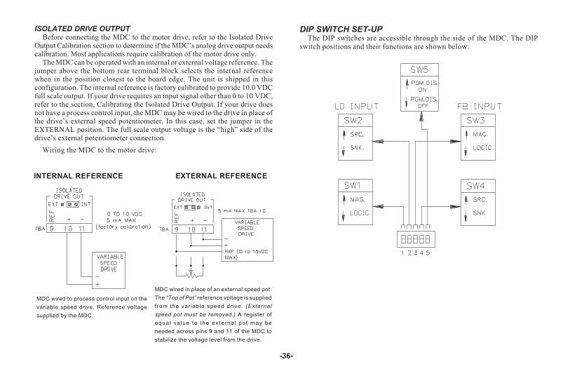
ISOLATED DRIVE OUTPUTBefore connecting the MDC to the motor drive, refer to the Isolated Drive
Output Calibration section to determine if the MDC’s analog drive output needscalibration. Most applications require calibration of the motor drive only.
The MDC can be operated with an internal or external voltage reference. Thejumper above the bottom rear terminal block selects the internal referencewhen in the position closest to the board edge. The unit is shipped in thisconfiguration. The internal reference is factory calibrated to provide 10.0 VDCfull scale output. If your drive requires an input signal other than 0 to 10 VDC,refer to the section, Calibrating the Isolated Drive Output. If your drive doesnot have a process control input, the MDC may be wired to the drive in place ofthe drive’s external speed potentiometer. In this case, set the jumper in theEXTERNAL position. The full scale output voltage is the “high” side of thedrive’s external potentiometer connection.
Wiring the MDC to the motor drive:
DIP SWITCH SET-UPThe DIP switches are accessible through the side of the MDC. The DIP
switch positions and their functions are shown below:
-36-
INTERNAL REFERENCE EXTERNAL REFERENCE
MDC wired to process control input on the
variable speed drive. Reference voltage
supplied by the MDC.
MDC wired in place of an external speed pot.
The “Top of Pot” reference voltage is supplied
from the variable speed drive. (External
speed pot must be removed.) A register of
equal value to the external pot may be
needed across pins 9 and 11 of the MDC to
stabilize the voltage level from the drive.
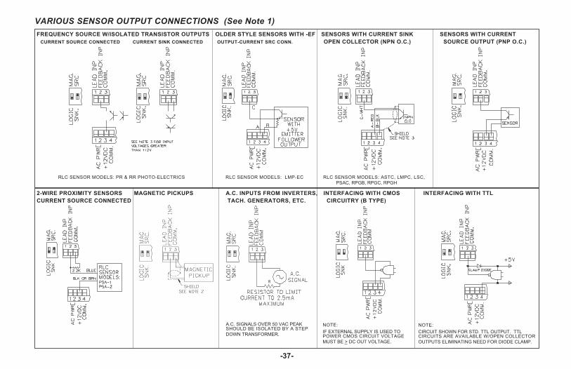
-37-
FREQUENCY SOURCE W/ISOLATED TRANSISTOR OUTPUTS OLDER STYLE SENSORS WITH -EF SENSORS WITH CURRENT SINK SENSORS WITH CURRENT
CURRENT SOURCE CONNECTED CURRENT SINK CONNECTED OUTPUT-CURRENT SRC CONN. OPEN COLLECTOR (NPN O.C.) SOURCE OUTPUT (PNP O.C.)
2-WIRE PROXIMITY SENSORS MAGNETIC PICKUPS A.C. INPUTS FROM INVERTERS, INTERFACING WITH CMOS INTERFACING WITH TTL
CURRENT SOURCE CONNECTED TACH. GENERATORS, ETC. CIRCUITRY (B TYPE)
A.C. SIGNALS OVER 50 VAC PEAKSHOULD BE ISOLATED BY A STEP
DOWN TRANSFORMER.
NOTE:
IF EXTERNAL SUPPLY IS USED TOPOWER CMOS CIRCUIT VOLTAGE
MUST BE > DC OUT VOLTAGE.
NOTE:
CIRCUIT SHOWN FOR STD. TTL OUTPUT. TTLCIRCUITS ARE AVAILABLE W/OPEN COLLECTOR
OUTPUTS ELIMINATING NEED FOR DIODE CLAMP.
VARIOUS SENSOR OUTPUT CONNECTIONS (See Note 1)
RLC SENSOR MODELS: ASTC, LMPC, LSC,
PSAC, RPGB, RPGC, RPGH
RLC SENSOR MODELS: PR & RR PHOTO-ELECTRICS RLC SENSOR MODELS: LMP-EC

NOTES:
1. SENSOR VOLTAGE AND CURRENTThe +12 VDC (out) terminal can supply voltage to a sensor within a �25%variation, due to line and internal load variations. All RLC sensors willaccommodate this variation.
2. When shielded cable is used, the shield should be connected to “COMM.”at the unit and left disconnected at the sensor end.
3. The Lead and Feedback frequency inputs can accept source pulses fromother circuits up to +28 V in amplitude. For voltages above +28 V, a limitingresistor and zener diode should be used to limit the voltage at the input.
-38-
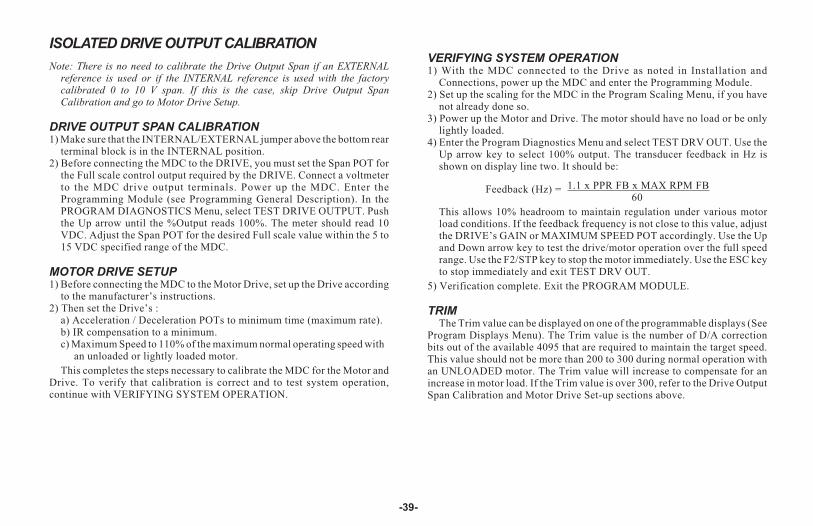
ISOLATED DRIVE OUTPUT CALIBRATION
Note: There is no need to calibrate the Drive Output Span if an EXTERNALreference is used or if the INTERNAL reference is used with the factorycalibrated 0 to 10 V span. If this is the case, skip Drive Output SpanCalibration and go to Motor Drive Setup.
DRIVE OUTPUT SPAN CALIBRATION1) Make sure that the INTERNAL/EXTERNAL jumper above the bottom rear
terminal block is in the INTERNAL position.2) Before connecting the MDC to the DRIVE, you must set the Span POT for
the Full scale control output required by the DRIVE. Connect a voltmeterto the MDC drive output terminals. Power up the MDC. Enter theProgramming Module (see Programming General Description). In thePROGRAM DIAGNOSTICS Menu, select TEST DRIVE OUTPUT. Pushthe Up arrow until the %Output reads 100%. The meter should read 10VDC. Adjust the Span POT for the desired Full scale value within the 5 to15 VDC specified range of the MDC.
MOTOR DRIVE SETUP1) Before connecting the MDC to the Motor Drive, set up the Drive according
to the manufacturer’s instructions.2) Then set the Drive’s :
a) Acceleration / Deceleration POTs to minimum time (maximum rate).b) IR compensation to a minimum.c) Maximum Speed to 110% of the maximum normal operating speed with
an unloaded or lightly loaded motor.
This completes the steps necessary to calibrate the MDC for the Motor andDrive. To verify that calibration is correct and to test system operation,continue with VERIFYING SYSTEM OPERATION.
VERIFYING SYSTEM OPERATION1) With the MDC connected to the Drive as noted in Installation and
Connections, power up the MDC and enter the Programming Module.2) Set up the scaling for the MDC in the Program Scaling Menu, if you have
not already done so.3) Power up the Motor and Drive. The motor should have no load or be only
lightly loaded.4) Enter the Program Diagnostics Menu and select TEST DRV OUT. Use the
Up arrow key to select 100% output. The transducer feedback in Hz isshown on display line two. It should be:
Feedback (Hz) = 1.1 x PPR FB x MAX RPM FB60
This allows 10% headroom to maintain regulation under various motorload conditions. If the feedback frequency is not close to this value, adjustthe DRIVE’s GAIN or MAXIMUM SPEED POT accordingly. Use the Upand Down arrow key to test the drive/motor operation over the full speedrange. Use the F2/STP key to stop the motor immediately. Use the ESC keyto stop immediately and exit TEST DRV OUT.
5) Verification complete. Exit the PROGRAM MODULE.
TRIMThe Trim value can be displayed on one of the programmable displays (See
Program Displays Menu). The Trim value is the number of D/A correctionbits out of the available 4095 that are required to maintain the target speed.This value should not be more than 200 to 300 during normal operation withan UNLOADED motor. The Trim value will increase to compensate for anincrease in motor load. If the Trim value is over 300, refer to the Drive OutputSpan Calibration and Motor Drive Set-up sections above.
-39-
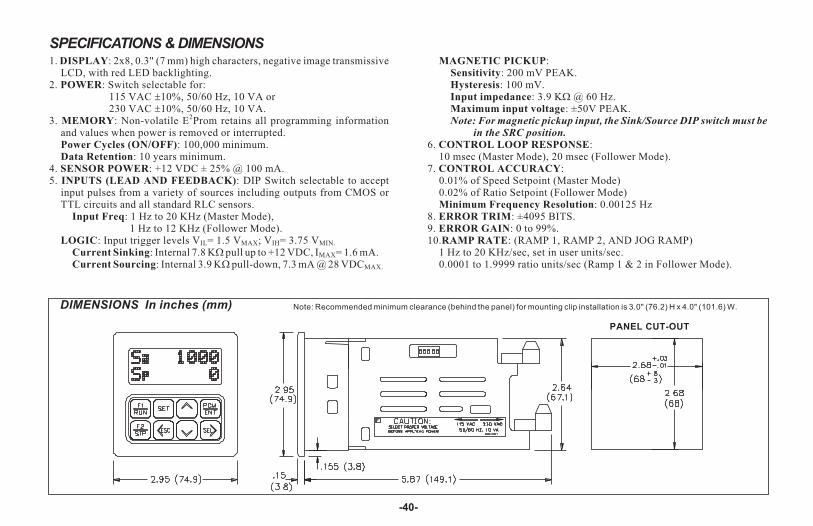
SPECIFICATIONS & DIMENSIONS1. DISPLAY: 2x8, 0.3" (7 mm) high characters, negative image transmissive
LCD, with red LED backlighting.2. POWER: Switch selectable for:
115 VAC �10%, 50/60 Hz, 10 VA or230 VAC �10%, 50/60 Hz, 10 VA.
3. MEMORY: Non-volatile E2Prom retains all programming informationand values when power is removed or interrupted.Power Cycles (ON/OFF): 100,000 minimum.Data Retention: 10 years minimum.
4. SENSOR POWER: +12 VDC ± 25% @ 100 mA.5. INPUTS (LEAD AND FEEDBACK): DIP Switch selectable to accept
input pulses from a variety of sources including outputs from CMOS orTTL circuits and all standard RLC sensors.
Input Freq: 1 Hz to 20 KHz (Master Mode),1 Hz to 12 KHz (Follower Mode).
LOGIC: Input trigger levels VIL= 1.5 VMAX; VIH= 3.75 VMIN.
Current Sinking: Internal 7.8 K� pull up to +12 VDC, IMAX= 1.6 mA.Current Sourcing: Internal 3.9 K� pull-down, 7.3 mA @ 28 VDCMAX.
MAGNETIC PICKUP:Sensitivity: 200 mV PEAK.Hysteresis: 100 mV.Input impedance: 3.9 K� @ 60 Hz.Maximum input voltage: ±50V PEAK.Note: For magnetic pickup input, the Sink/Source DIP switch must be
in the SRC position.
6. CONTROL LOOP RESPONSE:10 msec (Master Mode), 20 msec (Follower Mode).
7. CONTROL ACCURACY:0.01% of Speed Setpoint (Master Mode)0.02% of Ratio Setpoint (Follower Mode)Minimum Frequency Resolution: 0.00125 Hz
8. ERROR TRIM: ±4095 BITS.9. ERROR GAIN: 0 to 99%.10.RAMP RATE: (RAMP 1, RAMP 2, AND JOG RAMP)
1 Hz to 20 KHz/sec, set in user units/sec.0.0001 to 1.9999 ratio units/sec (Ramp 1 & 2 in Follower Mode).
-40-
DIMENSIONS In inches (mm)
PANEL CUT-OUT
Note: Recommended minimum clearance (behind the panel) for mounting clip installation is 3.0" (76.2) H x 4.0" (101.6) W.
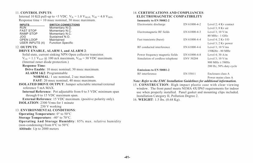
11. CONTROL INPUTS:Internal 10 K� pull-up to +5 VDC. VIL = 1.0 VMAX, VIH = 4.0 VMIN.
Response time = 10 msec nominal, 30 msec maximum.
INPUTS SWITCH CONNECTIONS
RUN Momentary N.O.FAST STOP Momentary N.C.RAMP STOP Momentary N.C.JOG Sustained N.O.OPEN LOOP MaintainedUSER INPUTS (4) Function Specific
12. OUTPUTS:DRIVE ENABLE, ALARM 1, and ALARM 2:
Solid state, current sinking NPN Open collector transistor.VCE = 1.1 VSAT @ 100 mA maximum, VOH = 30 VDC maximum.(Internal zener diode protection.)Response Time:
Drive Enable: 10 msec nominal; 30 msec maximum.ALARM 1&2: Programmable
NORMAL: 1 sec nominal, 2 sec maximum.FAST: 20 msec nominal, 40 msec maximum.
ISOLATED DRIVE OUTPUT: Jumper selectable internal/externalreference 5 mA MAX.Internal Reference: Pot adjustable from 0 to 5 VDC minimum span
through 0 to 15 VDC maximum span.External Reference: 15 VDC maximum. (positive polarity only).
ISOLATION: 2300 Vrms for 1 minute250 V working
13. ENVIRONMENTAL CONDITIONS:Operating Temperature: 0° to 50°CStorage Temperature: -40° to 70°C.Operating And Storage Humidity: 85% max. relative humidity(non-condensing) from 0°C to 50°CAltitude: Up to 2000 meters
14. CERTIFICATIONS AND COMPLIANCES:ELECTROMAGNETIC COMPATIBILITY
Immunity to EN 50082-2
Electrostatic discharge EN 61000-4-2 Level 2; 4 Kv contact
Level 3; 8 Kv air
Electromagnetic RF fields EN 61000-4-3 Level 3; 10 V/m
80 MHz - 1 GHz
Fast transients (burst) EN 61000-4-4 Level 4; 2 Kv I/O
Level 3; 2 Kv power
RF conducted interference EN 61000-4-6 Level 3; 10 V/ms
150KHz - 80 MHz
Power frequency magnetic fields EN 61000-4-8 Level 4; 30 A/m
Simulation of cordless telephone ENV 50204 Level 3; 10 V/m
900 MHz � 5MHz
200 Hz, 50% duty cycle
Emissions to EN 50081-2
RF interference EN 55011 Enclosure class A
Power mains class A
Note: Refer to the EMC Installation Guidelines for additional information.
15. CONSTRUCTION: High impact plastic case with clear viewingwindow. The front panel meets NEMA 4X/IP65 requirements for indooruse when properly installed. Panel gasket and mounting clips included.Installation Category II, Pollution Degree 2.
16. WEIGHT: 1.5 lbs. (0.68 Kg).
-41-

TROUBLESHOOTING GUIDE
-42-
Use the Program Diagnostics Menu in the MDC to functionally test the system hardware. Each input andoutput can be tested independently. The following list may also help localize the problem.
For further technical assistance, contact technical support at the numbers listed on the back cover of theinstruction manual.
PROBLEMS POSSIBLE CAUSE REMEDIES
NO DISPLAY 1. Power off2. Improperly wired3. Voltage selector switch in the wrong position.4. Power in a Brown out condition.
1. Verify power.2. Check Wiring.3. Check switch position.4. Verify supply voltage.
CHECK SUM ERROR 1 OR 2 ON DISPLAY 1. Data error detected by processor.
2. Power turned off with the unit in theProgramming Module (after entering new data values).
1. Press “ENT” then “SEL”.a. Check all programming parameters.b. Check signal lines for possible noise sources.
2. Press “ENT” then “SEL”a. Reenter new values.
CANNOT ENTER PROGRAMMINGMENUS
1. Front panel disabled.
2. Wrong pro code number.
3. Unit in JOG mode.
1. Check Front Panel Accessible ProgrammingWith Program Disable section of the manual.
2. Enter correct number, (factory default is 0) or seesection above.
3. Place unit in STOP mode.
UNIT WILL NOT ACCEPT THEDESIRED USER SETPOINTS
1. User setpoint is out of range. 1. Check the limits listed in the User Setpointssection of the manual.
SETPOINT CAN BE VIEWEDBUT NOT CHANGED
1. Front panel disabled. 1. Verify programming in Program Options MenuOperator Access section.a. Check Front Panel Accessible Programming
with Program Disable section of the manual.
UNIT WILL NOT ENTER RUN MODE 1. R-STOP, F-STOP inputs wired incorrectly.
2. Unit in Program mode.3. Unit is in JOG mode.
1. R-STOP and F-STOP inputs must be held low or tied tocomm. to enter RUN mode.
2. RUN is disabled. Exit the programming module.3. Place unit in STOP mode.

TROUBLESHOOTING GUIDE (Cont’d)
-43-
PROBLEMS POSSIBLE CAUSE REMEDIES
UNIT WILL NOT ENTER JOG MODE 1. R-STOP, F-STOP inputs wired incorrectly.
2. Unit in Program mode.3. Unit is in RUN mode.
1. R-STOP and F-STOP inputs must be held lowor tied to comm. to enter JOG mode.
2. JOG is disabled. Exit the programming module.3. Place unit in STOP mode.
UNIT INDICATES ZERO SPEED(MOTOR RUNNING)
1. No feedback signal.2. Type of input signal incorrectly selected.3. Scaling parameters programmed incorrectly.
PPR, MAX RPM too large or DSP UNIT too small.
1. Check sensor connection. Verify power to sensor.2. Check DIP switch setting on side of unit.3. Check parameters in Program Scaling Menu.
Verify correct FB freq. in Program DiagnosticsMenu TEST DRV OUT.
MOTOR WILL NOT RUN WITHMDC IN “RUN” MODE
1. Motor or Drive problem.
2. Internal/External jumper for Drive Output in wrongposition.
3. MDC Isolated Drive Output improperly calibrated.
4. Speed or Ratio setpoint zero or too low.
5. In Follower mode and Lead input is zero.
1. Make sure motor and drive operate independentof MDC.
2. Refer to Installation and Connections section ofmanual.
3. See Isolated Drive Output Calibration sectionof manual. Verify operation using ProgramDiagnostics Menu TEST DRV OUT.
4. Check speed/ratio Setpoint 1 and 2.
5. Verify by programming a DISPLAY for Leadfrequency.
“NO FEEDBACK” MESSAGEDISPLAYED/UNIT ENTERSSTOP MODE
1. No feedback signal present.2. Drive improperly calibrated.3. MDC Isolated Drive Output improperly calibrated.
4. Large “dead band” in drive and motor response atlow speed.
1. Check sensor connection. Verify power to sensor.2. See drive manual.3. See Isolated Drive Output Calibration section
of manual.4. Disable Feedback Loss Detection in the
Program Options Menu.
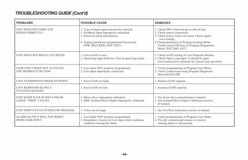
TROUBLESHOOTING GUIDE (Cont’d)
-44-
PROBLEMS POSSIBLE CAUSE REMEDIES
UNIT DOES NOT INDICATESPEED CORRECTLY
1. Type of input signal incorrectly selected.2. Feedback input improperly connected.3. Electrical noise interference.
4. Scaling parameters programmed incorrectly.(PPR, MAX RPM, DSP UNIT)
1. Check DIP switch set-up on side of unit.2. Check sensor connection.3. Check power source for noise. Check signal
wire routing.4.Check parameters in Program Scaling Menu.
Verify correct FB freq. in Program DiagnosticsMenu TEST DRV OUT.
UNIT DOES NOT REGULATE SPEED 1. Error GAIN is zero.2. Open loop input held low. Unit in open loop mode.
1. Check GAIN setting in User Setpoints Module.2. Check Open Loop input. It should be open
(not connected to common) for closed loop operation.
USER INPUT DOES NOT ACTIVATETHE DESIRED FUNCTION
1. User input NOT properly programmed.2. User input improperly connected.
1. Verify programming in Program User Menu.2. Verify connections using Program Diagnostic
Menu READ USR.
UNIT OVERSHOOTS SPEED SETPOINT 1. Error GAIN too high. 1. Reduce GAIN setpoint.
UNIT RESPONDS SLOWLYTO LOAD CHANGES
1. Error GAIN too low. 1. Increase GAIN setpoint.
UNIT RAMP RATE IS NON-LINEAR/LARGE “TRIM” VALUES
1. Motor drive improperly calibrated.2. MDC Isolated Drive Output improperly calibrated.
1. See motor drive manufacturer’s manual.2. See Isolated Drive Output Calibration section
of manual.
UNIT DISPLAYS AN OVERFLOW MESSAGE 1. Value out of range. 1. See Overflow Indication section of manual.
ALARM OUTPUT WILL NOT RESETFROM USER INPUT
1. User Input NOT properly programmed.2. Momentary closure on User Input while condition
condition causing the alarm.
1. Verify programming in Program User Menu.2. Provide a maintained closure or remove
causing alarm is still present.

-45-
MASTER MODE APPLICATION
A pump delivers 30.0 gallons per minute with a shaft speedof 1750 RPM. A shaft pulse encoder generates 60pulses/revolution. Set the MDC scaling to control anddisplay pumping speed in tenths of a gallon/minute.
1) Set the pulses per revolution feedback to 60.2) Set the maximum RPM feedback to 1750. This is the pump
shaft’s maximum operating speed.3) Set display decimal point to 0.0. Display units are in 0.1 gpm.4) Set max display units to 30.0. The display speed unit
maximum is 30.0 at a MAX RPM FB of 1750.
APPENDIX “A” APPLICATIONS

-46-
FOLLOWER MODE APPLICATION
A fertilizer production facility is mixing pellets containingNitrogen with pellets that contain Phosphorus. A chemical ratio of1:1 is determined by the speed of two different conveyors. Becauseof differences in the gearing of the conveyor and concentration ofthe pellets, the Nitrogen conveyor motor must run at 3 times thespeed of the Phosphorus conveyor motor in order to produce a 1:1mix. The maximum speed of both motors is 2000 RPM. Set thefollower MDC scaling to produce a 1:1 mix of Nitrogen andPhosphorus when a setpoint of 1.0000 is entered. Display speedunits are in RPM’s. Both the lead and feedback frequency are takenfrom 60 tooth gears on each motor shaft.
1) Choose the Phosphorus conveyor motor for the follower MDC.It runs slower than the Nitrogen conveyor motor.
2) Set the Pulses per revolution feedback to 60.3) Set the MAX RPM feedback to 2000. This is the conveyor
motor’s maximum operating speed.4) Set display decimal point to 0.5) Set display unit to 2000. The display speed unit maximum is
2000 at a MAX RPM FB of 2000. If the display units wantedwere conveyor feet/minute or Phosphorus pellets in lbs/sec, theequivalent display value for 2000 RPM would be entered.
6) Set the pulses per revolution lead to 60.7) Setting the MAX RPM Lead:
This is the Lead RPM that would be necessary to have a 1:1mixture if the Follower Speed was MAX RPM FB (2000 RPM).Since the Nitrogen conveyor motor must run 3 times as fast as thePhosphorus motor, MAX RPM LD = 3 x 2000 = 6000 RPM. SetMAX RPM LD = 6000 RPM. This is the correct value, even thoughthe Nitrogen conveyor motor would never actually run at 6000RPM. A ratio setpoint of 1.0000 on the MDC is now equal to a 1:1mixture of Phosphorus and Nitrogen.
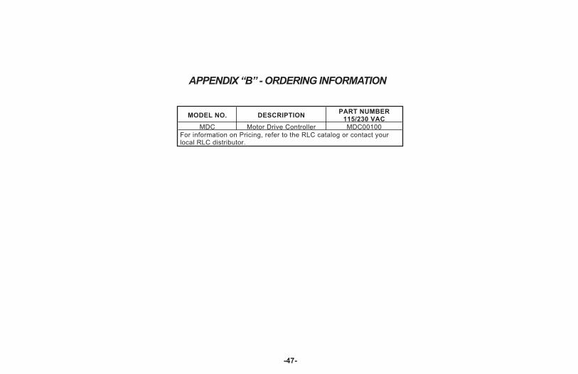
-47-
APPENDIX “B” - ORDERING INFORMATION
MODEL NO. DESCRIPTIONPART NUMBER
115/230 VAC
MDC Motor Drive Controller MDC00100
For information on Pricing, refer to the RLC catalog or contact yourlocal RLC distributor.

LIMITED WARRANTY
The Company warrants the products it manufactures against defects inmaterials and workmanship for a period limited to one year from the date ofshipment, provided the products have been stored, handled, installed, and usedunder proper conditions. The Company’s liability under this limited warrantyshall extend only to the repair or replacement of a defective product, at TheCompany’s option. The Company disclaims all liability for any affirmation,promise or representation with respect to the products.
The customer agrees to hold Red Lion Controls harmless from, defend, andindemnify RLC against damages, claims, and expenses arising out ofsubsequent sales of RLC products or products containing componentsmanufactured by RLC and based upon personal injuries, deaths, propertydamage, lost profits, and other matters which Buyer, its employees, or sub-contractors are or may be to any extent liable, including without limitationpenalties imposed by the Consumer Product Safety Act (P.L. 92-573) andliability imposed upon any person pursuant to the Magnuson-Moss WarrantyAct (P.L. 93-637), as now in effect or as amended hereafter.
No warranties expressed or implied are created with respect to The Company’sproducts except those expressly contained herein. The Customer acknowledgesthe disclaimers and limitations contained and relies on no other warranties oraffirmations.
MDC-COV.QXD 10/21/04 10:51 AM Page 3

MDC/IM - F 10/00DRAWING NO. LP0281
Red Lion Controls
20 Willow Springs Circle
York PA 17402
Tel +1 (717) 767-6511
Fax +1 (717) 764-0839
Red Lion Controls AP
31, Kaki Bukit Road 3,
#06-04/05 TechLink
Singapore 417818
Tel +65 6744-6613
Fax +65 6743-3360
Red Lion Controls BV
Basicweg 11b
NL - 3821 BR Amersfoort
Tel +31 (0) 334 723 225
Fax +31 (0) 334 893 793
MDC-COV.QXD 10/21/04 10:51 AM Page 4
![Compact and Discreet - yaesu.ru · Battery Life [5-5-90 duty with battery saver]MDC-1200® Features: - MDC-1200® ANI - MDC-1200® Call Alert - MDC-1200® Sel Call - MDC-1200® Radio](https://img.pdfslide.net/doc/110x75/5e80d3de6005c20fb639820d/compact-and-discreet-yaesuru-battery-life-5-5-90-duty-with-battery-savermdc-1200.jpg)