Embed Size (px)
Citation preview
Chapter 2
Chapter 2 Modeling Data in the Organization
Chapter Overview
The purpose of this chapter is to present a detailed description of the entity-relationship model and the use of this tool within the context of conceptual data modeling. This chapter presents the basic entity-relationship (or E-R) model, while advanced features are presented in Chapter 3.
Chapter Objectives
Specific student learning objectives are included in the beginning of the chapter. From an instructor’s point of view, the objectives of this chapter are to:1. Emphasize the importance of understanding organizational data, and convince your
students that unless they can represent data unambiguously in logical terms, they cannot implement a database that will effectively serve the needs of management.
2. Present the E-R model as a logical data model that can be used to capture the structure and much, although not all, of the semantics (or meaning) of data.
3. Apply E-R modeling concepts to several practical examples including the Pine Valley Furniture Company case.
Key Terms
Associative entity Entity-relationship diagram (E-R diagram)
Relationship instanceAttribute Relationship typeBinary relationship Entity-relationship model
(E-R model)Required attribute
Business rule Simple (or atomic) attributeCardinality constraint Fact Strong entity typeComposite attribute Identifier TermComposite identifier Identifying owner Ternary relationshipDegree Identifying relationship Time stampDerived attribute Maximum cardinality Unary relationshipEntity Minimum cardinality Weak entity typeEntity instance Multivalued attributeEntity type Optional attribute
Classroom Ideas
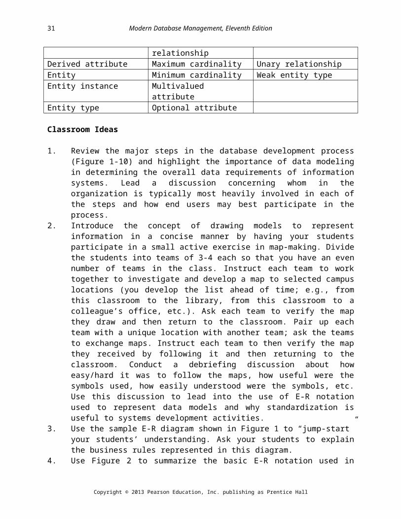
1. Review the major steps in the database development process (Figure 1-10) and highlight the importance of data modeling in determining the overall data requirements of information systems. Lead a discussion concerning whom in the organization is typically most heavily involved in each of the steps and how end users may best participate in the process.
2. Introduce the concept of drawing models to represent information in a concise manner by having your students participate in a small active exercise in map-making. Divide the students into teams of 3-4 each so that you have an even number of teams in the class.
Copyright © 2013 Pearson Education, Inc. publishing as Prentice Hall
30
Modern Database Management, Eleventh Edition
Instruct each team to work together to investigate and develop a map to selected campus locations (you develop the list ahead of time; e.g., from this classroom to the library, from this classroom to a colleague’s office, etc.). Ask each team to verify the map they draw and then return to the classroom. Pair up each team with a unique location with another team; ask the teams to exchange maps. Instruct each team to then verify the map they received by following it and then returning to the classroom. Conduct a debriefing discussion about how easy/hard it was to follow the maps, how useful were the symbols used, how easily understood were the symbols, etc. Use this discussion to lead into the use of E-R notation used to represent data models and why standardization is useful to systems development activities.
3. Use the sample E-R diagram shown in Figure 1 to “jump-start” your students’ understanding. Ask your students to explain the business rules represented in this diagram.
4. Use Figure 2 to summarize the basic E-R notation used in this chapter (and throughout the remainder of the text).
5. Contrast the terms: entity type and entity instance (see Figure 3). Discuss other examples: STUDENT (with each student in the classroom as an instance), etc. Warn the students that the term “entity” is often used either way; the meaning is intended to come from the context in which it is used.
6. Give examples of common errors in E-R diagramming, including inappropriate entities (see Figure 4). Ask your students for other examples.
7. Compare strong versus weak entities using Figure 5. Ask your students for other examples.
8. Discuss the various types of attributes that are commonly encountered (Figures 7 through 9). Again, ask your students to think of other examples.
9. Make sure your students understand the difference between relationship types and relationship instances (Figure 10).
10. Introduce the notion of an associative entity by using Figure 11. Discuss the four reasons (presented in the text) for converting a relationship to an associative entity.
11. Discuss unary, binary, and ternary relationships (Figure 12). Have the students brainstorm at least two additional examples for each of these relationship degrees.
12. Discuss the bill-of-materials unary relationship (Figure 13). Use a simple and familiar product (such as a toy) to illustrate this structure.
13. Introduce the concept and notation of cardinality constraints in relationships (Figures 16, 17, and 18). Emphasize that these constraints are important expressions of business rules.
14. Introduce the problem of representing time dependent data. Use Figures 19 and 20 to illustrate different means of coping with time dependencies.
15. Discuss examples of multiple relationships between entities (Figure 21). Ask your students to suggest other examples.
16. Use the diagram for Pine Valley Furniture Company (Figure 22) to illustrate a more comprehensive E-R diagram. Stress that in real-world situations, E-R diagrams are often much more complex than this example.
17. As time permits, have your students work in small teams, 2 or 3 students each, to solve some of the E-R diagramming exercises at the end of the chapter. We have included a number of new examples for this purpose. Also, you may assign the project case as a homework exercise.
Copyright © 2013 Pearson Education, Inc. publishing as Prentice Hall
31
Chapter 2
Answers to Review Questions
1. Define each of the following terms:a. Entity type. A collection of entities that share common properties or
characteristicsb. Entity-relationship model. A logical representation of the data for an organization
or for a business areac. Entity instance. A single occurrence of an entity typed. Attribute. A property or characteristic of an entity type that is of interest to the
organizatione. Relationship type. A meaningful association between (or among) entity typesf. Identifier. An attribute (or combination of attributes) that uniquely identifies
individual instances of an entity typeg. Multivalued attribute. An attribute that may take on more than one value for a
given entity instanceh. Associative entity. An entity type that associates the instances of one or more
entity types and contains attributes that are peculiar to the relationship between those entity instances
i. Cardinality constraint. Specifies the number of instances of one entity that can (or must) be associated with each instance of another entity
j. Weak entity. An entity type whose existence depends on some other entity typek. Identifying relationship. The relationship between a weak entity type and its
ownerl. Derived attribute. An attribute whose values can be calculated from related
attribute valuesm. Business rule. A statement that defines or constrains some aspect of the business
2. Match the following terms and definitions:i composite attributed associative entityb unary relationshipj weak entityh attributem entitye relationship typec cardinality constraintg degreea identifierf entity typek ternaryl bill-of-materials
Copyright © 2013 Pearson Education, Inc. publishing as Prentice Hall
32
Modern Database Management, Eleventh Edition
3. Contrast the following terms:a. Stored attribute; derived attribute. A stored attribute is one whose values are
stored in the database, while a derived attribute is one whose values can be calculated or derived from related stored attributes.
b. Simple attribute; composite attribute. A simple attribute is one that cannot be broken down into smaller components, while a composite attribute can be broken down into component parts.
c. Entity type; relationship type. An entity type is a collection of entities that share common properties or characteristics, while a relationship type is a meaningful association between (or among) entity types.
d. Strong entity type; weak entity type. A strong entity type is an entity that exists independently of other entity types, while a weak entity type depends on some other entity type.
e. Degree; cardinality. The degree (of a relationship) is the number of entity types that participate in that relationship, while cardinality is a constraint on the number of instances of one entity that can (or must) be associated with each instance of another entity.
f. Required attribute; optional attribute. A required attribute must have a value for each entity instance, whereas an optional attribute may not have a value for every entity instance.
g. Composite attribute; multivalued attribute. A composite attribute has component parts that give meaning, whereas a multivalued attribute may take one or more values for an entity instance.
h. Ternary relationship; three binary relationships. A ternary relationship is a simultaneous relationship among the instances of three entity types and often includes attributes unique to that simultaneous relationship. Three binary relationships reflect the three two-way relationships between two entity types, and do not depict the same meaning as a ternary relationship.
4. Three reasons:a. The characteristics of data captured during data modeling are crucial in the design
of databases, programs, and other system components. Facts and rules that are captured during this process are essential in assuring data integrity in an information system.
b. Data, rather than processes, are the most important aspects of many modern information systems and hence, require a central role in structuring system requirements.
c. Data tend to be more stable than the business processes that use the data. Thus, an information system that is based on a data orientation should have a longer useful life than one based on a process orientation.
5. Four reasons:a. Business rules are a core concept in an enterprise since they are an expression of
business policy, and they guide individual and aggregate behavior. Well-structured business rules can be stated in a natural language for end users and in a data model for system developers.
Copyright © 2013 Pearson Education, Inc. publishing as Prentice Hall
33
Chapter 2
b. Business rules can be expressed in terms that are familiar to end users. Thus, users can define and then maintain their own rules.
c. Business rules are highly maintainable: they are stored in a central repository and each rule is expressed only once, then shared throughout the organization.
d. Enforcement of business rules can be automated through the use of software that can interpret the rules and enforce them using the integrity mechanisms of the database management system.
6. Where can you find business rules? Business rules appear in descriptions of business functions, events, policies, units, stakeholders, and other objects. These descriptions can be found in interview notes from individual and group information systems requirements collection sessions, organizational documents, and other sources. Rules are identified by asking questions about the who, what, when, where, why, and how of the organization.
7. Six general guidelines:a. Data names should relate to business, not technical characteristics.b. Data names should be meaningful, almost to the point of being self-documenting.c. Data names should be unique from the name used for every other distinct data
object.d. Data names should be readable, so the name is structured as the concept would
most naturally be said.e. Data names should be composed of words taken from an approved list.f. Data names should be repeatable, meaning that different people or the same
person at different times should develop exactly or almost the same name.
8. Four criteria:a. Choose an identifier that will not change its value over the life of each instance of
the entity type.b. Choose an identifier such that for each instance of the entity the attribute is
guaranteed to have valid values and not be null (or unknown).c. Avoid the use of so-called intelligent identifiers (or keys), whose structure
indicates classifications, locations, and so on.d. Consider substituting single-attribute surrogate identifiers for large composite
identifiers.
9. Why composite rather than simple?An identifier attribute is an attribute (or combination of attributes) whose value distinguishes individual instances of an entity type. Often, a simple attribute will not be unique for all instances of an entity type (e.g., FlightNumber for an instance of an airline flight). Rather, a combination of simple attributes will be needed to uniquely identify the entity instance (e.g., FlightID and FlightDate would make the instance unique).
Copyright © 2013 Pearson Education, Inc. publishing as Prentice Hall
34
Modern Database Management, Eleventh Edition
10. Three conditions for an associative entity type:a. All of the relationships for the participating entity types are “many” relationships.b. The resulting associative entity type has independent meaning to end users, and it
preferably can be identified with a single-attribute identifier.c. The associative entity has one or more attributes in addition to the identifier.
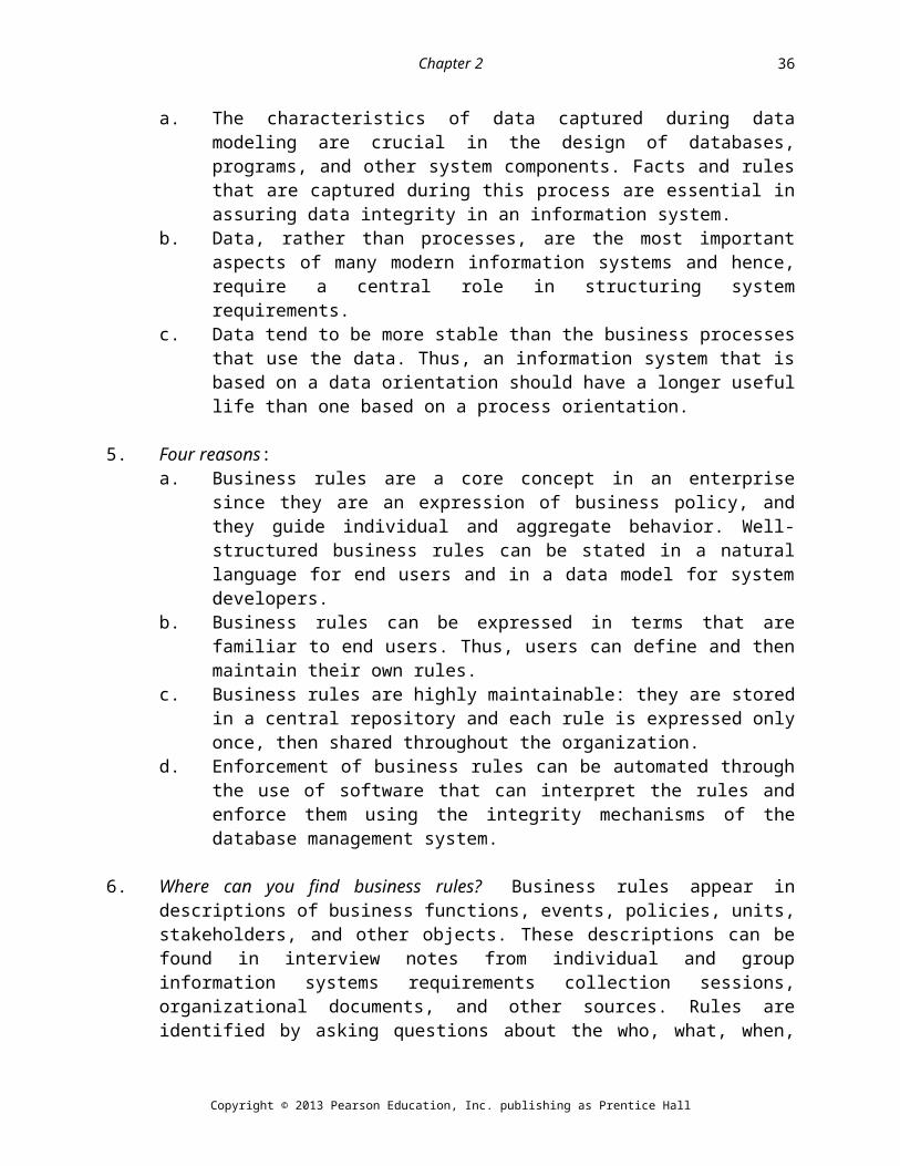
11. Four types of cardinality constraints:a. Optional one:
PERSON BICYCLEOwns
b. Mandatory one:
TEAM LEADERLead By
c. Optional many:
STUDENT COURSERegisters For
d. Mandatory many:
COURSE TEXTBOOKUses
Copyright © 2013 Pearson Education, Inc. publishing as Prentice Hall
35
Chapter 2
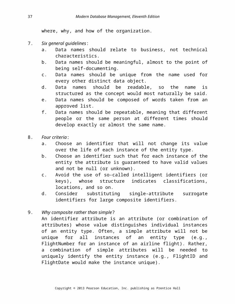
12. Example of weak entity: Phone Call (see below) is an example of a weak entity because a phone call must be placed by a PERSON. In this simple example, PHONE CALL is related to only one other entity type, thus, it is not necessary to show the identifying relationship; however, if this data model were ever expanded so that PHONE CALL related to other entity types, it is good practice to always indicate the identifying relationship.
PERSON PHONE CALLPlaces
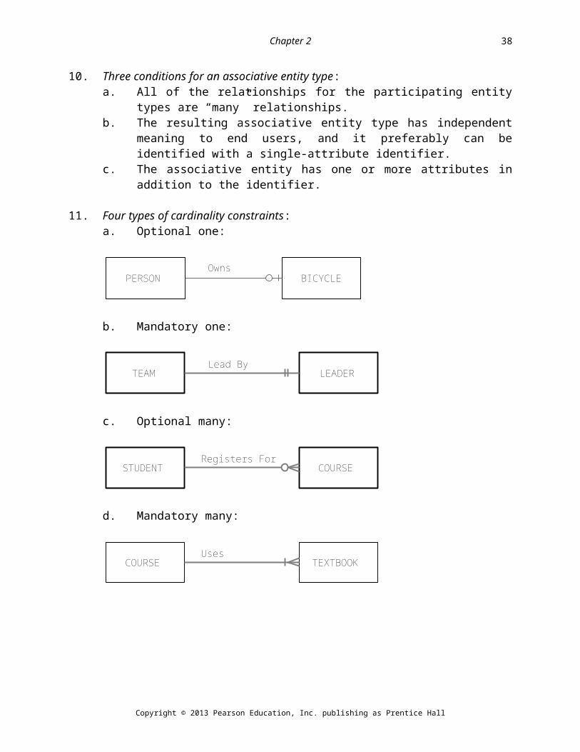
13. Degree of relationship definition & examples:The degree of a relationship is the number of entity types that participate in the relationship.a) Unary (one entity type):
Related To
PERSON
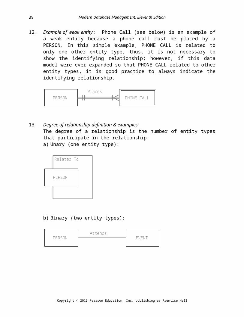
b) Binary (two entity types):
PERSON EVENTAttends
Copyright © 2013 Pearson Education, Inc. publishing as Prentice Hall
36
Modern Database Management, Eleventh Edition
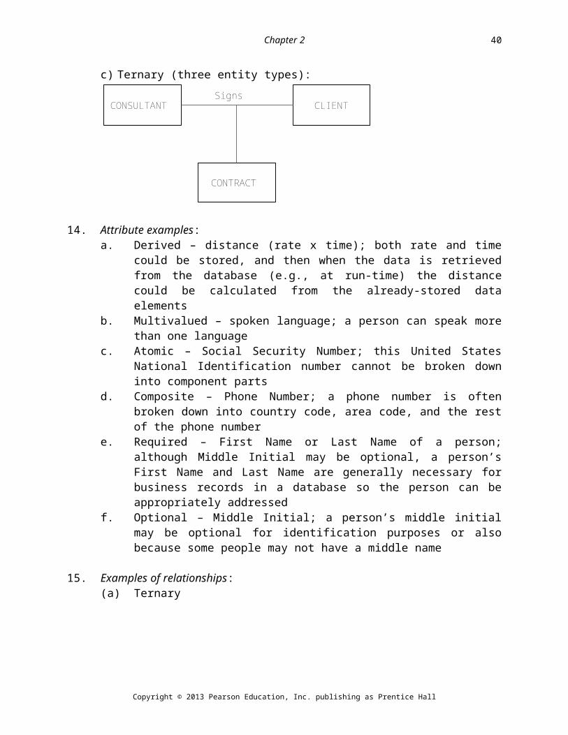
c) Ternary (three entity types):
CONSULTANT CLIENT
CONTRACT
Signs
14. Attribute examples:a. Derived – distance (rate x time); both rate and time could be stored, and then
when the data is retrieved from the database (e.g., at run-time) the distance could be calculated from the already-stored data elements
b. Multivalued – spoken language; a person can speak more than one languagec. Atomic – Social Security Number; this United States National Identification
number cannot be broken down into component partsd. Composite – Phone Number; a phone number is often broken down into country
code, area code, and the rest of the phone numbere. Required – First Name or Last Name of a person; although Middle Initial may be
optional, a person’s First Name and Last Name are generally necessary for business records in a database so the person can be appropriately addressed
f. Optional – Middle Initial; a person’s middle initial may be optional for identification purposes or also because some people may not have a middle name
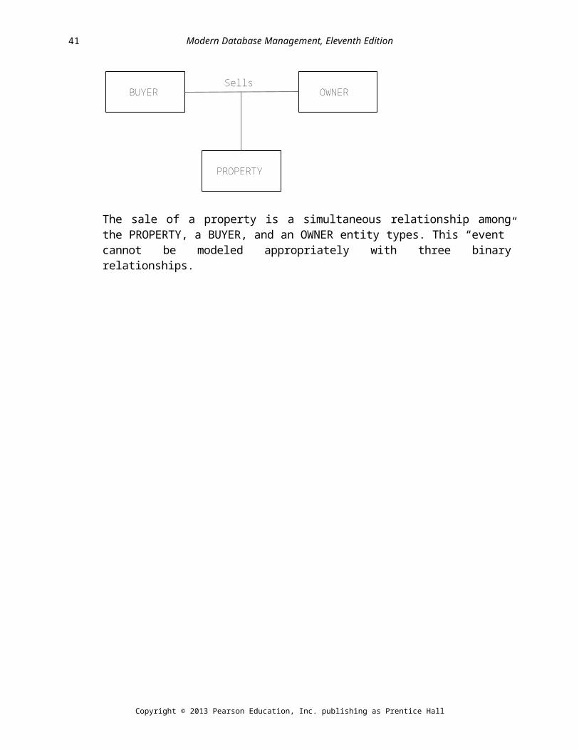
15. Examples of relationships:(a) Ternary
BUYER OWNER
PROPERTY
Sells
The sale of a property is a simultaneous relationship among the PROPERTY, a BUYER, and an OWNER entity types. This “event” cannot be modeled appropriately with three binary relationships.
Copyright © 2013 Pearson Education, Inc. publishing as Prentice Hall
37
Chapter 2
15. Examples of relationships (continued):
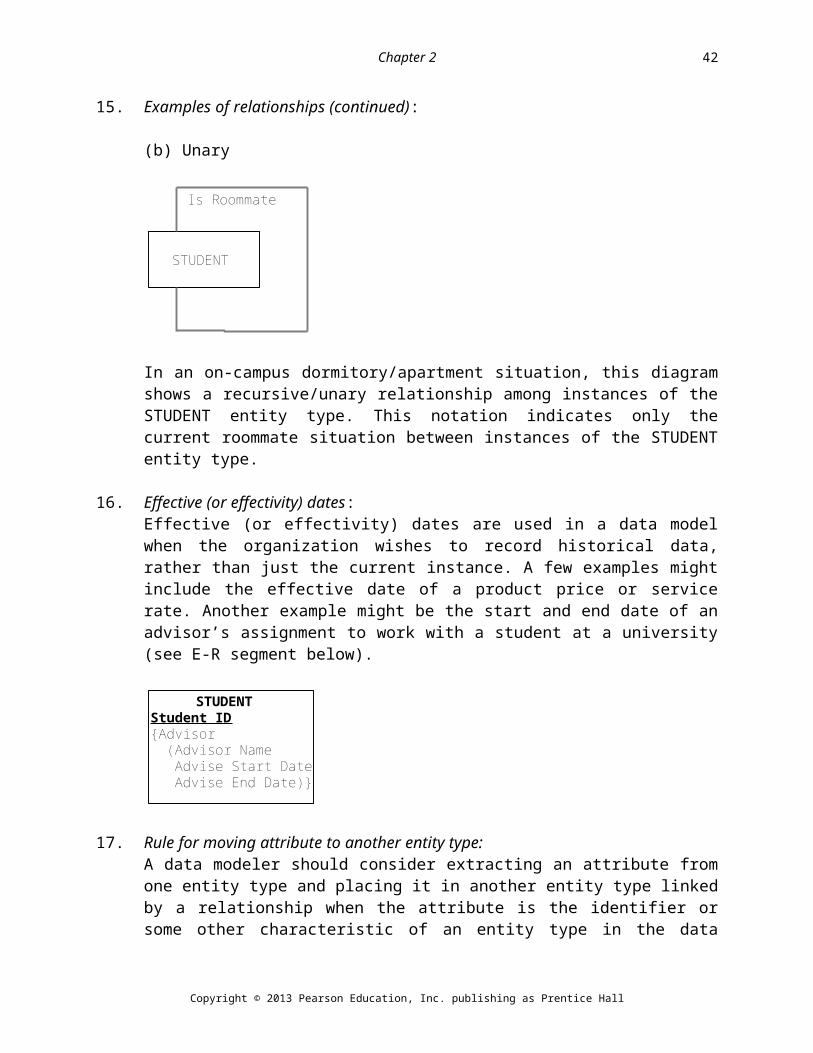
(b) Unary
Is Roommate
STUDENT
In an on-campus dormitory/apartment situation, this diagram shows a recursive/unary relationship among instances of the STUDENT entity type. This notation indicates only the current roommate situation between instances of the STUDENT entity type.
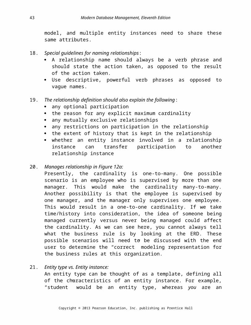
16. Effective (or effectivity) dates: Effective (or effectivity) dates are used in a data model when the organization wishes to record historical data, rather than just the current instance. A few examples might include the effective date of a product price or service rate. Another example might be the start and end date of an advisor’s assignment to work with a student at a university (see E-R segment below).
STUDENTStudent ID{Advisor (Advisor Name Advise Start Date Advise End Date)}
17. Rule for moving attribute to another entity type:A data modeler should consider extracting an attribute from one entity type and placing it in another entity type linked by a relationship when the attribute is the identifier or some other characteristic of an entity type in the data model, and multiple entity instances need to share these same attributes.
18. Special guidelines for naming relationships: A relationship name should always be a verb phrase and should state the action taken,
as opposed to the result of the action taken. Use descriptive, powerful verb phrases as opposed to vague names.
19. The relationship definition should also explain the following: any optional participation the reason for any explicit maximum cardinality
Copyright © 2013 Pearson Education, Inc. publishing as Prentice Hall
38
Modern Database Management, Eleventh Edition
any mutually exclusive relationships any restrictions on participation in the relationship the extent of history that is kept in the relationship whether an entity instance involved in a relationship instance can transfer
participation to another relationship instance
20. Manages relationship in Figure 12a:Presently, the cardinality is one-to-many. One possible scenario is an employee who is supervised by more than one manager. This would make the cardinality many-to-many. Another possibility is that the employee is supervised by one manager, and the manager only supervises one employee. This would result in a one-to-one cardinality. If we take time/history into consideration, the idea of someone being managed currently versus never being managed could affect the cardinality. As we can see here, you cannot always tell what the business rule is by looking at the ERD. These possible scenarios will need to be discussed with the end user to determine the “correct” modeling representation for the business rules at this organization.
21. Entity type vs. Entity instance:An entity type can be thought of as a template, defining all of the characteristics of an entity instance. For example, “student” would be an entity type, whereas you are an instance of “student.”
22. Conversion of ternary relationship to associative entity:Converting a ternary relationship into an associative entity is recommended for two main reasons: (1) researchers have shown that participation/cardinality constraints cannot be accurately represented for a ternary relationship with current notation; and (2) most E-R diagramming tools cannot represent ternary relationships. By converting a ternary relationship into an associative entity with three mandatory binary relationships, a data modeler can accurately represent the participation/cardinality constraints although the meaning/semantics of the original ternary relationship is lost with this solution.
Copyright © 2013 Pearson Education, Inc. publishing as Prentice Hall
39
Chapter 2
Answers to Problems and Exercises
1. Cellular Operator Database Figure 24 questions:
a. Can a customer have an unlimited number of plans?
Yes. A Customer may be responsible for 0, 1, or many Plans.
b. Can a customer exist without a plan?
Yes. The minimum cardinality of the Belongs relationship from the Customer to the Plan states that a Customer may exist without a Plan (the minimum cardinality is 0).
c. Is it possible to create a plan without knowing who the customer is?
No. The minimum cardinality of both the “responsible for” and “belongs” relationships between Plan and Customer states that at least one Customer must be related to a Plan.
d. Does the operator want to limit the types of handsets that can be linked to a specific plan type?
Yes, the cellular operator requires that a Handset (that is a particular type and a particular operating system) is linked to one Plan (that is a particular type of plan). This business rule is to be implemented in this design by indirectly requiring that a Plan Type has 0:M Plans, and each Plan is associated with certain Handsets, and each Handset is of some Handset Type. A given Plan Type is related to Handset Type through the intermediary entity types in this design.
[Alternative interpretation: No, there is nothing in the current model that creates a condition that would limit – in advance – the handset types that can be related to a specific plan type.]
e. Is it possible to maintain data regarding a handset without connecting it to a plan?
Yes. The minimum cardinality of the Includes relationship between Plan and Handset states that a Handset may be included in 0 or 1 plan. The 0 minimum cardinality means that we can track data about the handset even if it is not connected to a plan; the Handset has optional participation in the Includes relationship with Plan.
f. Can a handset be associated with multiple plans?
No. The minimum cardinality of the Includes relationship between Plan and Handset states that a Handset may be included in 0 or 1 plan, not multiple plans.
g. Assume a handset type exists that can utilize multiple operating systems. Could this situation be accommodated within the model included in Figure 24?
Copyright © 2013 Pearson Education, Inc. publishing as Prentice Hall
40
Modern Database Management, Eleventh Edition
No. The current model shows that a handset type is associated with one and only one operating system.
h. Is the company able to track a manufacturer without maintaining information about its handsets?
Yes. The minimum cardinality of the relationship between Manufacturer and Handset Type indicates that we can track data about a Manufacturer even if we have no (or zero) Handset Types in our database.
i. Can the same operating system be used on multiple handset types?
Yes. The maximum cardinality on the relationship between Operating System and Handset Type indicates that an Operating System may be used on 0, 1, or many Handset types.
j. There are two relationships between Customer and Plan. Explain how they differ.
The Responsible For relationship is an overall 1:M relationship between Customer and Plan. A Customer can be responsible for 0, 1, or many Plans yet any one Plan will be linked to only 1 Customer for responsibility purposes. The Belongs relationship is an overall M:M relationship that permits the linking of multiple customers to a single plan, as in the case of family members being part of a particular plan or different plans.
k. Characterize the degree and the cardinalities of the relationship that connects Customer to itself. Explain its meaning.
The “Family Member” relationship that connects Customer to itself has a degree of 1 (unary). It permits the tracking of each family member as a Customer. Any Customer may be a Family Member of 0, 1, or many Customer(s); As a Family Member Customer, the Customer may be linked to 0 or 1 Customer.
l. Is it possible to link a handset to a specific customer in a plan with multiple customers?
No, not in the current model. However, the current model could be adjusted to create an Associative Entity to track the particular Customer instance with a particular Plan instance, that is then associated with a particular Handset. This suggested extension to the current model also permits a design that will easily extend the database’s ability to track additional data about the particular Customer instance with a particular Plan instance.
m. Can the company track a handset without identifying its operating system?
No. The minimum cardinality of the relationship between Handset Type and Operating System is 1 and only 1; the minimum of 1 is a mandatory participation for the Handset
Copyright © 2013 Pearson Education, Inc. publishing as Prentice Hall
41
Chapter 2
Type with the Operating System.
2. For each of the descriptions below, perform the following tasks:
i) Identify the degree and cardinalities of the relationship. ii) Express the relationships in each description graphically with an E-R diagram
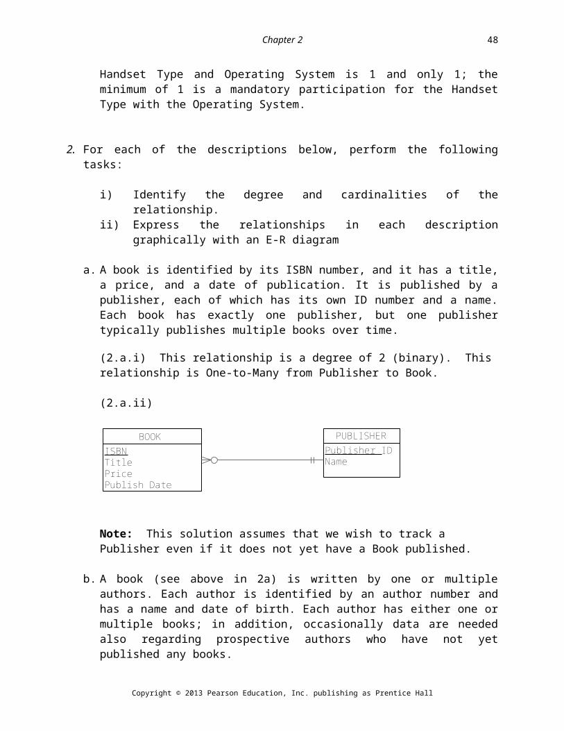
a. A book is identified by its ISBN number, and it has a title, a price, and a date of publication. It is published by a publisher, each of which has its own ID number and a name. Each book has exactly one publisher, but one publisher typically publishes multiple books over time.
(2.a.i) This relationship is a degree of 2 (binary). This relationship is One-to-Many from Publisher to Book.
(2.a.ii)
BOOKISBNTitlePricePublish Date
PUBLISHERPublisher IDName
Note: This solution assumes that we wish to track a Publisher even if it does not yet have a Book published.
b. A book (see above in 2a) is written by one or multiple authors. Each author is identified by an author number and has a name and date of birth. Each author has either one or multiple books; in addition, occasionally data are needed also regarding prospective authors who have not yet published any books.
(2.b.i) This relationship is a degree of 2 (binary). This relationship is Many-to-Many from Author to Book.
(2.b.ii)
BOOKISBNTitlePricePublish Date
AUTHORAuthor NumberNameDate of Birth
Copyright © 2013 Pearson Education, Inc. publishing as Prentice Hall
42
Modern Database Management, Eleventh Edition
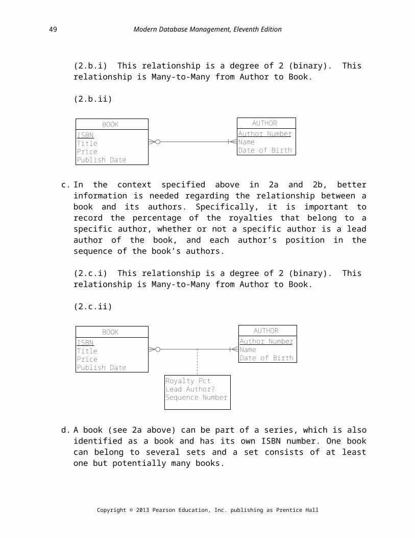
c. In the context specified above in 2a and 2b, better information is needed regarding the relationship between a book and its authors. Specifically, it is important to record the percentage of the royalties that belong to a specific author, whether or not a specific author is a lead author of the book, and each author’s position in the sequence of the book’s authors.
(2.c.i) This relationship is a degree of 2 (binary). This relationship is Many-to-Many from Author to Book.
(2.c.ii)
BOOKISBNTitlePricePublish Date
AUTHORAuthor NumberNameDate of Birth
Royalty PctLead Author?Sequence Number
d. A book (see 2a above) can be part of a series, which is also identified as a book and has its own ISBN number. One book can belong to several sets and a set consists of at least one but potentially many books.
(2.d.i) This relationship is a degree of 1 (unary). This relationship is Many-to-Many.
(2.d.ii) This solution assumes that “series” and “sets” are synonymous terms. The question does not require that a series have any special attributes or distinguishing features, so it can be represented in the data model like any other Book instance and identified by ISBN.
BOOKISBNTitlePricePublish Date
Belongs To
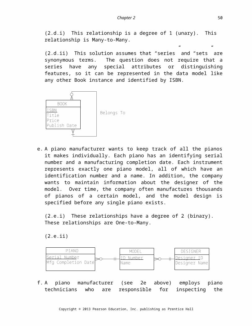
e. A piano manufacturer wants to keep track of all the pianos it makes individually. Each piano has an identifying serial number and a manufacturing completion date. Each instrument represents exactly one piano model, all of which have an identification number and a name. In addition, the company wants to maintain information about the
Copyright © 2013 Pearson Education, Inc. publishing as Prentice Hall
43
Chapter 2
designer of the model. Over time, the company often manufactures thousands of pianos of a certain model, and the model design is specified before any single piano exists.
(2.e.i) These relationships have a degree of 2 (binary). These relationships are One-to-Many.
(2.e.ii)
PIANOSerial NumberMfg Completion Date
MODELID NumberName
DESIGNERDesigner IDDesigner Name
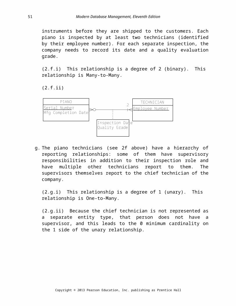
f. A piano manufacturer (see 2e above) employs piano technicians who are responsible for inspecting the instruments before they are shipped to the customers. Each piano is inspected by at least two technicians (identified by their employee number). For each separate inspection, the company needs to record its date and a quality evaluation grade.
(2.f.i) This relationship is a degree of 2 (binary). This relationship is Many-to-Many.
(2.f.ii)
PIANOSerial NumberMfg Completion Date
TECHNICIANEmployee Number
Inspection DateQuality Grade
2
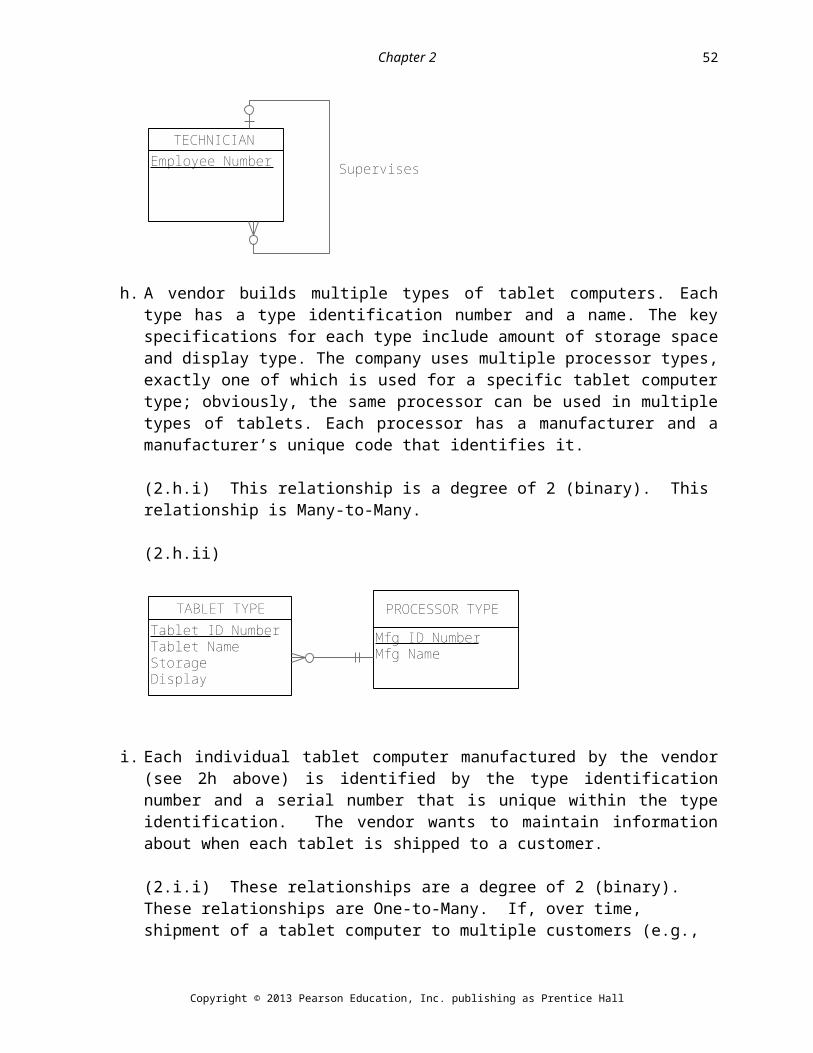
g. The piano technicians (see 2f above) have a hierarchy of reporting relationships: some of them have supervisory responsibilities in addition to their inspection role and have multiple other technicians report to them. The supervisors themselves report to the chief technician of the company.
(2.g.i) This relationship is a degree of 1 (unary). This relationship is One-to-Many.
(2.g.ii) Because the chief technician is not represented as a separate entity type, that person does not have a supervisor, and this leads to the 0 minimum cardinality on the 1 side of the unary relationship.
Copyright © 2013 Pearson Education, Inc. publishing as Prentice Hall
44
Modern Database Management, Eleventh Edition
TECHNICIANEmployee Number Supervises
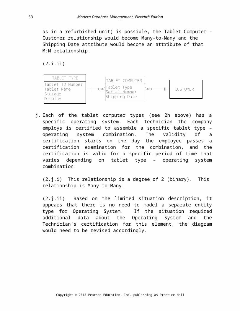
h. A vendor builds multiple types of tablet computers. Each type has a type identification number and a name. The key specifications for each type include amount of storage space and display type. The company uses multiple processor types, exactly one of which is used for a specific tablet computer type; obviously, the same processor can be used in multiple types of tablets. Each processor has a manufacturer and a manufacturer’s unique code that identifies it.
(2.h.i) This relationship is a degree of 2 (binary). This relationship is Many-to-Many.
(2.h.ii)
TABLET TYPETablet ID NumberTablet NameStorageDisplay
PROCESSOR TYPE
Mfg ID NumberMfg Name
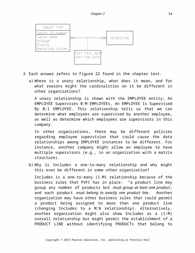
i. Each individual tablet computer manufactured by the vendor (see 2h above) is identified by the type identification number and a serial number that is unique within the type identification. The vendor wants to maintain information about when each tablet is shipped to a customer.
(2.i.i) These relationships are a degree of 2 (binary). These relationships are One-to-Many. If, over time, shipment of a tablet computer to multiple customers (e.g., as in a refurbished unit) is possible, the Tablet Computer – Customer relationship would become Many-to-Many and the Shipping Date attribute would become an attribute of that M:M relationship.
(2.i.ii)
Copyright © 2013 Pearson Education, Inc. publishing as Prentice Hall
45
Chapter 2
TABLET TYPETablet ID NumberTablet NameStorageDisplay
TABLET COMPUTERTablet TypeSerial NumberShipping Date
CUSTOMER
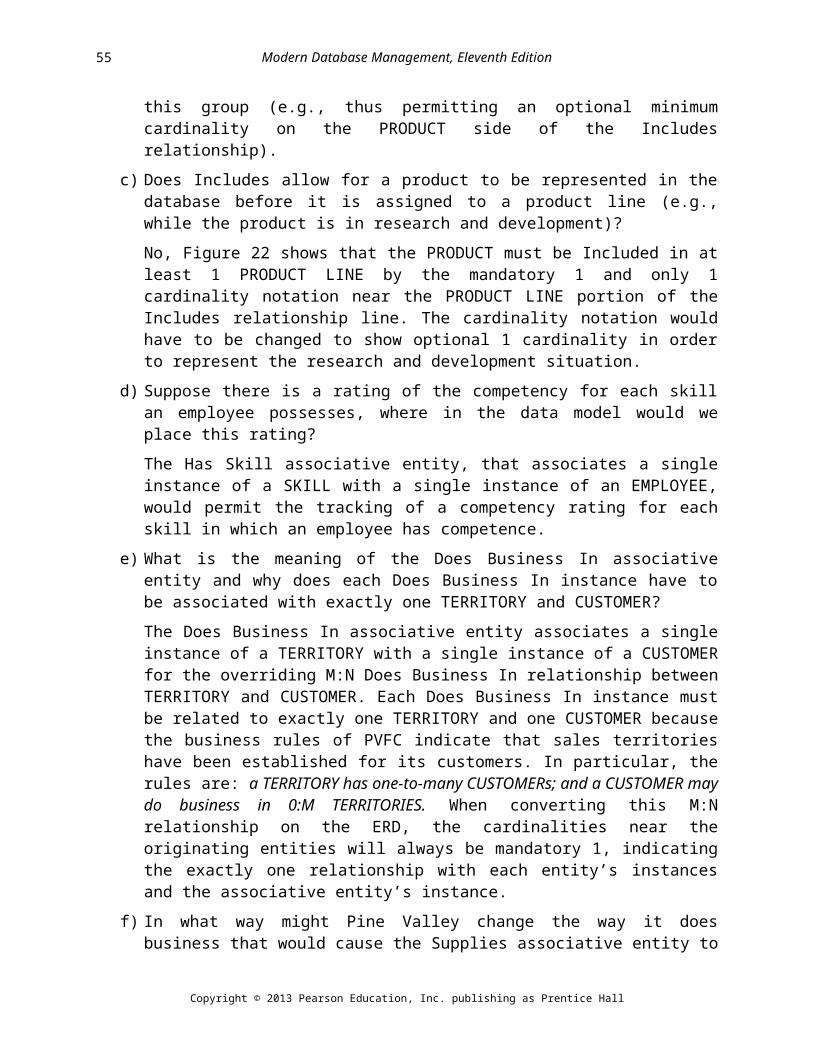
j. Each of the tablet computer types (see 2h above) has a specific operating system. Each technician the company employs is certified to assemble a specific tablet type – operating system combination. The validity of a certification starts on the day the employee passes a certification examination for the combination, and the certification is valid for a specific period of time that varies depending on tablet type – operating system combination.
(2.j.i) This relationship is a degree of 2 (binary). This relationship is Many-to-Many.
(2.j.ii) Based on the limited situation description, it appears that there is no need to model a separate entity type for Operating System. If the situation required additional data about the Operating System and the Technician’s certification for this element, the diagram would need to be revised accordingly.
TABLET TYPE
Tablet ID NumberTablet NameStorageDisplayOperating System
TECHNICIAN
Cert Pass DateCert End Date
3. Each answer refers to Figure 22 found in the chapter text.
a) Where is a unary relationship, what does it mean, and for what reasons might the cardinalities on it be different in other organizations?
A unary relationship is shown with the EMPLOYEE entity; An EMPLOYEE Supervises 0:M EMPLOYEEs, An EMPLOYEE Is Supervised By 0:1 EMPLOYEE. This relationship tells us that we can determine what employees are supervised by another employee, as well as determine which employees are supervisors in this company.
In other organizations, there may be different policies regarding employee supervision that could cause the data relationships among EMPLOYEE instances to be different. For instance, another company might allow an employee to have multiple supervisors (e.g., in an organization with a matrix structure).
b) Why is Includes a one-to-many relationship and why might this ever be different in some other organization?
Copyright © 2013 Pearson Education, Inc. publishing as Prentice Hall
46
Modern Database Management, Eleventh Edition
Includes is a one-to-many (1:M) relationship because of the business rules that PVFC has in place: “a product line may group any number of products but must group at least one product; and each product must belong to exactly one product line.” Another organization may have other business rules that could permit a product being assigned to more than one product line (changing Includes to a M:N relationship). Alternatively, another organization might also show Includes as a (1:M) overall relationship but might permit the establishment of a PRODUCT LINE without identifying PRODUCTs that belong to this group (e.g., thus permitting an optional minimum cardinality on the PRODUCT side of the Includes relationship).
c) Does Includes allow for a product to be represented in the database before it is assigned to a product line (e.g., while the product is in research and development)?
No, Figure 22 shows that the PRODUCT must be Included in at least 1 PRODUCT LINE by the mandatory 1 and only 1 cardinality notation near the PRODUCT LINE portion of the Includes relationship line. The cardinality notation would have to be changed to show optional 1 cardinality in order to represent the research and development situation.
d) Suppose there is a rating of the competency for each skill an employee possesses, where in the data model would we place this rating?
The Has Skill associative entity, that associates a single instance of a SKILL with a single instance of an EMPLOYEE, would permit the tracking of a competency rating for each skill in which an employee has competence.
e) What is the meaning of the Does Business In associative entity and why does each Does Business In instance have to be associated with exactly one TERRITORY and CUSTOMER?
The Does Business In associative entity associates a single instance of a TERRITORY with a single instance of a CUSTOMER for the overriding M:N Does Business In relationship between TERRITORY and CUSTOMER. Each Does Business In instance must be related to exactly one TERRITORY and one CUSTOMER because the business rules of PVFC indicate that sales territories have been established for its customers. In particular, the rules are: a TERRITORY has one-to-many CUSTOMERs; and a CUSTOMER may do business in 0:M TERRITORIES. When converting this M:N relationship on the ERD, the cardinalities near the originating entities will always be mandatory 1, indicating the exactly one relationship with each entity’s instances and the associative entity’s instance.
f) In what way might Pine Valley change the way it does business that would cause the Supplies associative entity to be eliminated and the relationships around it change?
According to current business practice at PVFC, each RAW MATERIAL is provided by 1 or more VENDORs and a VENDOR supplies 0, 1, or many RAW MATERIALs and this is represented by the Supplies associative entity. The PVFC could consider entering into exclusive supplier arrangements with particular vendors such that an instance of RAW MATERIAL is supplied by only 1 VENDOR. If that situation should occur, then the overall relationship between RAW MATERIAL and VENDOR would change to 1:M (instead of M:N) and the Supply Unit Price attribute could become part of the RAW
Copyright © 2013 Pearson Education, Inc. publishing as Prentice Hall
47
Chapter 2
MATERIAL entity instance; the Supplies associative entity would no longer need to be on the ERD.
4. Analysis of Figure 22:4.1. Entities PRODUCT, PRODUCT LINE; relationship Includes4.2. Entities CUSTOMER, ORDER; relationship Submits4.3. Entities ORDER, PRODUCT; associative entity ORDER LINE4.4. Entities CUSTOMER, TERRITORY; associative entity Does Business In4.5. Entities SALESPERSON, TERRITORY; relationship Serves4.6. Entities PRODUCT, RAW MATERIAL; relationship Uses4.7. Entities RAW MATERIAL, VENDOR; relationship Supplies4.8. Entities WORK CENTER, PRODUCT; associative entity Produced In4.9. Entities EMPLOYEE, WORK CENTER; associative entity Works In4.10. Entity EMPLOYEE; relationship Supervises, Is Supervised By
5. Use of CASE or drawing tool: Student answers will vary based on the CASE or drawing tool that is used and their personal experiences. The answers should describe their experiences with the CASE or drawing tool in terms of the requirements of the E-R notation used in the chapter. Expect to see students make reference to noting identifiers, using associative entities, using cardinality constraints properly, indicating required vs. optional attributes, and noting derived/composite/multivalued attributes.
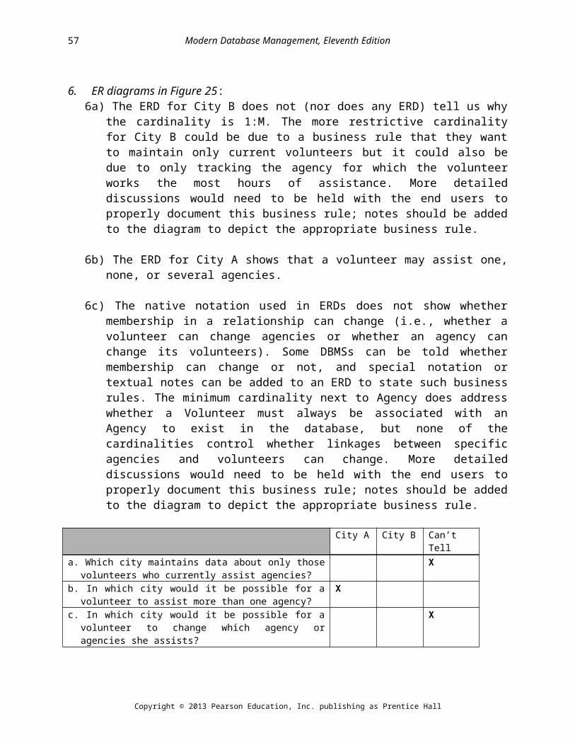
6. ER diagrams in Figure 25:6a) The ERD for City B does not (nor does any ERD) tell us why the cardinality is 1:M. The
more restrictive cardinality for City B could be due to a business rule that they want to maintain only current volunteers but it could also be due to only tracking the agency for which the volunteer works the most hours of assistance. More detailed discussions would need to be held with the end users to properly document this business rule; notes should be added to the diagram to depict the appropriate business rule.
6b) The ERD for City A shows that a volunteer may assist one, none, or several agencies.
6c) The native notation used in ERDs does not show whether membership in a relationship can change (i.e., whether a volunteer can change agencies or whether an agency can change its volunteers). Some DBMSs can be told whether membership can change or not, and special notation or textual notes can be added to an ERD to state such business rules. The minimum cardinality next to Agency does address whether a Volunteer must always be associated with an Agency to exist in the database, but none of the cardinalities control whether linkages between specific agencies and volunteers can change. More detailed discussions would need to be held with the end users to properly document this business rule; notes should be added to the diagram to depict the appropriate business rule.
City A City B Can’t Tella. Which city maintains data about only those volunteers who
currently assist agencies?X
b. In which city would it be possible for a volunteer to assist more X
Copyright © 2013 Pearson Education, Inc. publishing as Prentice Hall
48
Modern Database Management, Eleventh Edition
than one agency?c. In which city would it be possible for a volunteer to change
which agency or agencies she assists?X
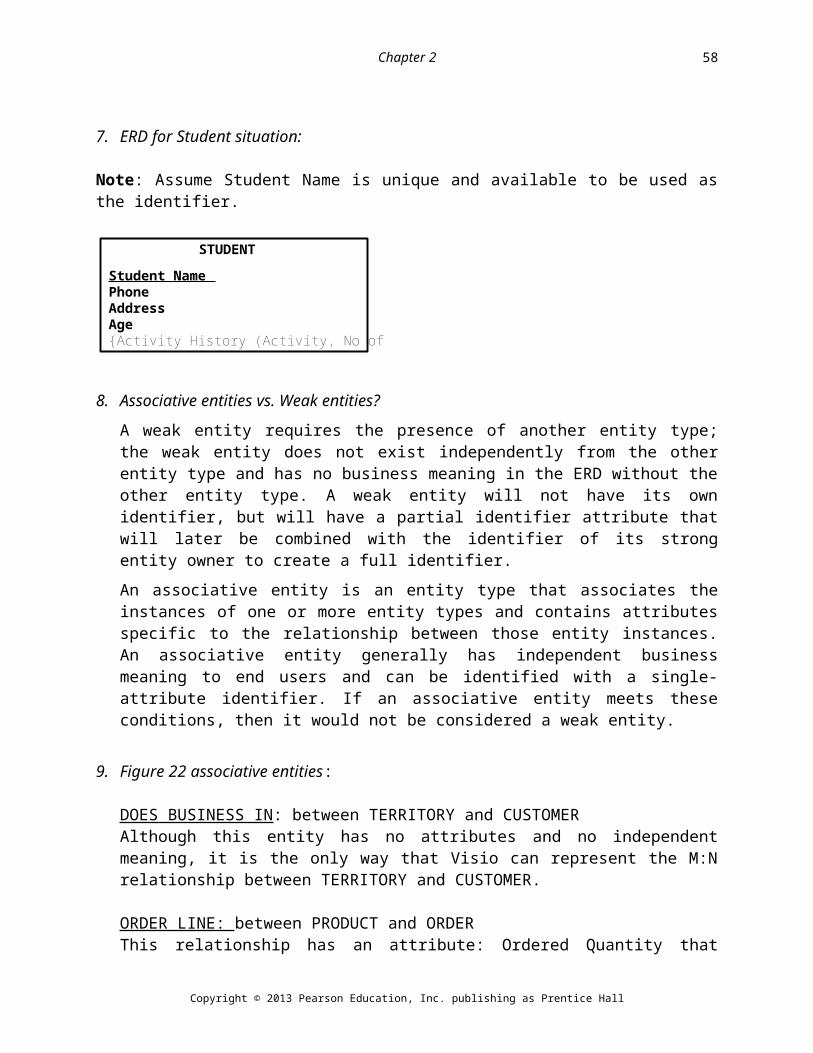
7. ERD for Student situation:
Note: Assume Student Name is unique and available to be used as the identifier.
STUDENTStudent NamePhoneAddressAge{Activity History (Activity, No of Yrs)}
8. Associative entities vs. Weak entities?
A weak entity requires the presence of another entity type; the weak entity does not exist independently from the other entity type and has no business meaning in the ERD without the other entity type. A weak entity will not have its own identifier, but will have a partial identifier attribute that will later be combined with the identifier of its strong entity owner to create a full identifier.
An associative entity is an entity type that associates the instances of one or more entity types and contains attributes specific to the relationship between those entity instances. An associative entity generally has independent business meaning to end users and can be identified with a single-attribute identifier. If an associative entity meets these conditions, then it would not be considered a weak entity.
9. Figure 22 associative entities:
DOES BUSINESS IN: between TERRITORY and CUSTOMERAlthough this entity has no attributes and no independent meaning, it is the only way that Visio can represent the M:N relationship between TERRITORY and CUSTOMER.
ORDER LINE: between PRODUCT and ORDERThis relationship has an attribute: Ordered Quantity that reflects the amount of product on each line of the order by the customer. It has independent meaning on the Customer’s Order.
USES: between PRODUCT and RAW MATERIALThis relationship has one attribute, Goes Into Quantity. It also may have independent meaning, although there is no obvious independent identifier.
SUPPLIES: between RAW MATERIAL and VENDOR
Copyright © 2013 Pearson Education, Inc. publishing as Prentice Hall
49
Chapter 2
Since there is an attribute on this entity and it can have independent meaning, it might be a good candidate to convert to an associative entity.
PRODUCED IN: between WORK CENTER and PRODUCTAlthough this entity has no attributes and no independent meaning, it is the only way that Visio can represent the M:N relationship between WORK CENTER and PRODUCT.
WORKS IN: between WORK CENTER and EMPLOYEEAlthough this entity has no attributes and no independent meaning, it is the only way that Visio can represent the M:N relationship between WORK CENTER and EMPLOYEE.
HAS SKILL: between EMPLOYEE and SKILLAlthough this entity has no attributes and no independent meaning, it is the only way that Visio can represent the M:N relationship between SKILL and EMPLOYEE.
There are so many associative entities because there are many M:N relationships that have independent meaning and because Visio’s templates cannot represent M:N relationships.
Copyright © 2013 Pearson Education, Inc. publishing as Prentice Hall
50
Modern Database Management, Eleventh Edition
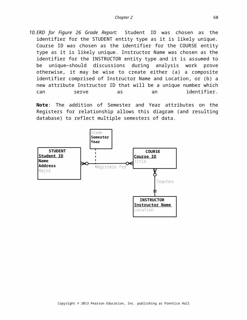
10. ERD for Figure 26 Grade Report: Student ID was chosen as the identifier for the STUDENT entity type as it is likely unique. Course ID was chosen as the identifier for the COURSE entity type as it is likely unique. Instructor Name was chosen as the identifier for the INSTRUCTOR entity type and it is assumed to be unique—should discussions during analysis work prove otherwise, it may be wise to create either (a) a composite identifier comprised of Instructor Name and Location, or (b) a new attribute Instructor ID that will be a unique number which can serve as an identifier.
Note: The addition of Semester and Year attributes on the Registers for relationship allows this diagram (and resulting database) to reflect multiple semesters of data.
STUDENTStudent IDNameAddressMajor
COURSECourse IDTitle
INSTRUCTORInstructor NameLocation
Teaches
GradeSemesterYear
Registers For
Copyright © 2013 Pearson Education, Inc. publishing as Prentice Hall
51
Chapter 2
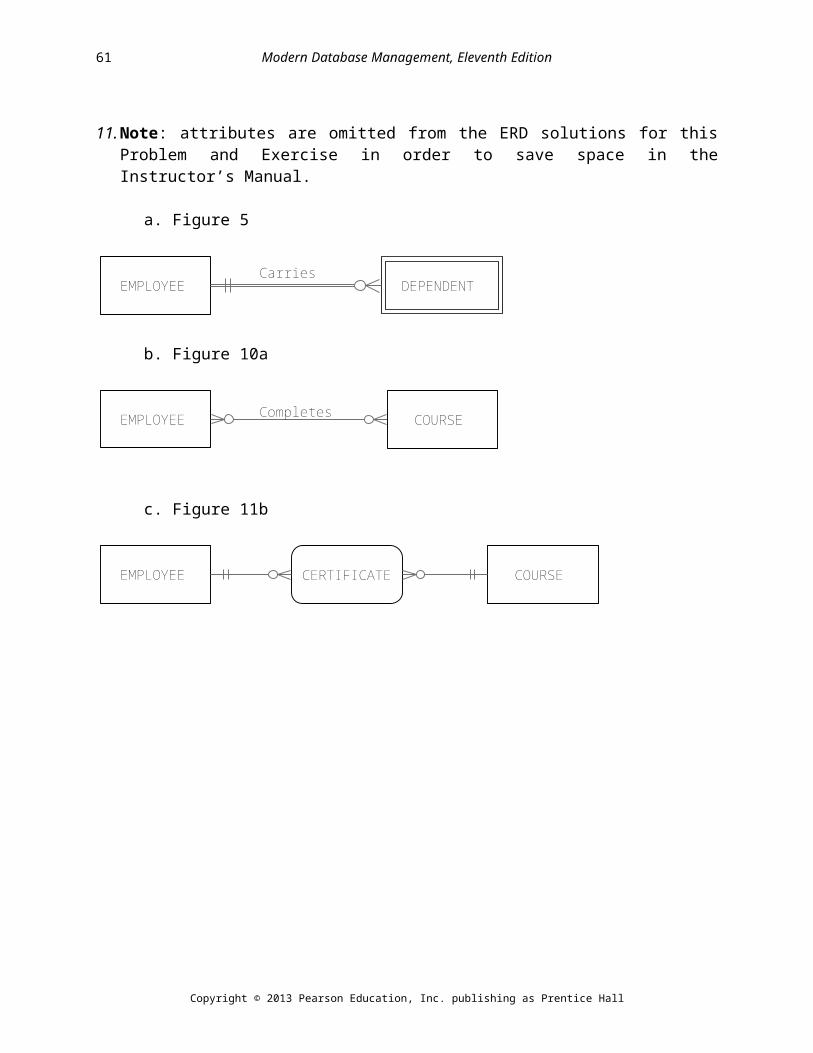
11. Note: attributes are omitted from the ERD solutions for this Problem and Exercise in order to save space in the Instructor’s Manual.
a. Figure 5
EMPLOYEE DEPENDENTCarries
b. Figure 10a
EMPLOYEE Completes COURSE
c. Figure 11b
EMPLOYEE COURSECERTIFICATE
Copyright © 2013 Pearson Education, Inc. publishing as Prentice Hall
52
Modern Database Management, Eleventh Edition
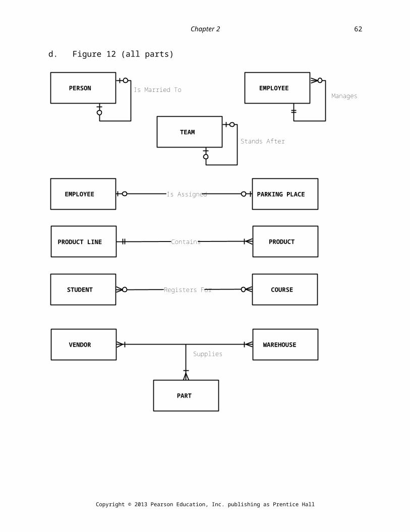
d. Figure 12 (all parts)
PERSON
EMPLOYEE
Is Married To EMPLOYEE
TEAM
Manages
Stands After
PARKING PLACEIs Assigned
PRODUCT LINE PRODUCTContains
STUDENT COURSERegisters For
VENDOR WAREHOUSE
PART
Supplies
Copyright © 2013 Pearson Education, Inc. publishing as Prentice Hall
53
Chapter 2
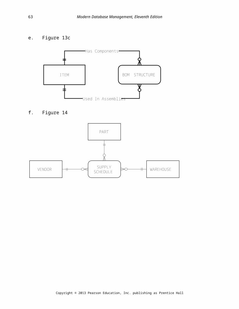
e. Figure 13c
ITEM BOM STRUCTURE
Has Components
Used In Assemblies
f. Figure 14
VENDOR
PART
WAREHOUSESUPPLYSCHEDULE
Copyright © 2013 Pearson Education, Inc. publishing as Prentice Hall
54
Modern Database Management, Eleventh Edition
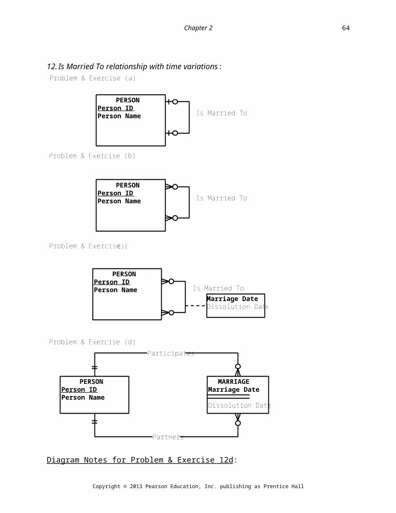
12. Is Married To relationship with time variations:
PERSONPerson IDPerson Name Is Married To
Problem & Exercise (a)
Problem & Exercise (b)
PERSONPerson IDPerson Name Is Married To
Problem & Exercise (c)
PERSONPerson IDPerson Name Is Married To
Marriage DateDissolution Date
PERSONPerson IDPerson Name
MARRIAGEMarriage Date
Dissolution Date
Problem & Exercise (d)
Participates
Partners
Diagram Notes for Problem & Exercise 12d: This solution presumes that Marriage Date is a partial identifier of the MARRIAGE
Copyright © 2013 Pearson Education, Inc. publishing as Prentice Hall
55
Chapter 2
entity; a full composite identifier will include Marriage Date and the two Person IDs involved in the marriage. The solution also assumes that the same two people do not get married, dissolved, and re-married on the same date. Adding a Marriage Time attribute (also a part of the identifier) would permit this situation to be covered by this model.
An alternate solution would be to use a surrogate identifier of License No instead of the suggested composite identifier of Marriage Date and the two Person IDs for the MARRIAGE entity.
Problem & Exercise 12e:
The solution in 12d does not place any restrictions on the number of persons to whom any one person is simultaneously married, thus the 12d solution is sufficient in representing the lack of legal restrictions regarding the number of marriage partners.
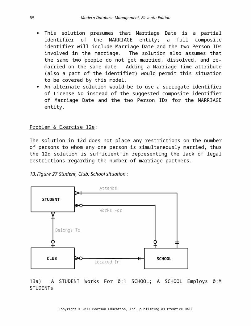
13. Figure 27 Student, Club, School situation:
STUDENT
CLUB SCHOOL
Belongs To
Works For
Attends
Located In
13a) A STUDENT Works For 0:1 SCHOOL; A SCHOOL Employs 0:M STUDENTs
13b) A STUDENT may belong to a CLUB only when located in the SCHOOL s/he Attends
13c) Student answers may vary. Alternative solutions include: Since the STUDENT may not Work For a SCHOOL (the employment is optional), the
Works For relationship is needed in the diagram in order to properly represent this business rule. This solution makes it harder for the database to enforce the business rule that a STUDENT works for the SCHOOL that s/he attends, but opens up the possibility that a STUDENT could Work For a SCHOOL that s/he is not currently attending.
An alternative design would be to remove the Works For relationship, and add an attribute to STUDENT named Works that would have a binary (Y/N) value to represent whether or not the STUDENT instance is working for the SCHOOL s/he Attends. The
Copyright © 2013 Pearson Education, Inc. publishing as Prentice Hall
56
Modern Database Management, Eleventh Edition
advantage of this design is that it would enforce the business rule that a STUDENT can only Work For a SCHOOL that s/he is currently attending.
Copyright © 2013 Pearson Education, Inc. publishing as Prentice Hall
57
Chapter 2
14. Figure 28 diagrams showing stock price history:
Note: Student answers may vary. The crux of the answer relies upon what the purpose of the ER diagram is for the modeling situation and how end users in the organization “see” the situation. In particular, do people in the organization have a term for stock price and refer to it as its own concept?
If so, solution B may be the “better” way to model this situation. Instructors may also use solution B to demonstrate an issue related to view integration (topic in chapter 4) where transitive dependencies emerge; solution B makes the model easy to expand so that stock prices may have relationships that do not directly involve the STOCK entity.
Solution A indicates that each STOCK has multiple prices and is well-suited to early discussions with end users about the data needs of a system. Solution B adds the precision of multiple STOCK PRICE entity instances occurring for each STOCK entity instance. Solution B indicates that STOCK PRICE is a weak entity whose instances do not exist independently in the database without a corresponding STOCK entity instance. Solution B presents more precise detail of the data relationships that will likely be developed in the logical design of the database; this model may more closely resemble the relational model implementation of this design. Solution B also makes it easy to expand the model so that stock prices may have relationships with other entities that do not directly involve the STOCK entity.
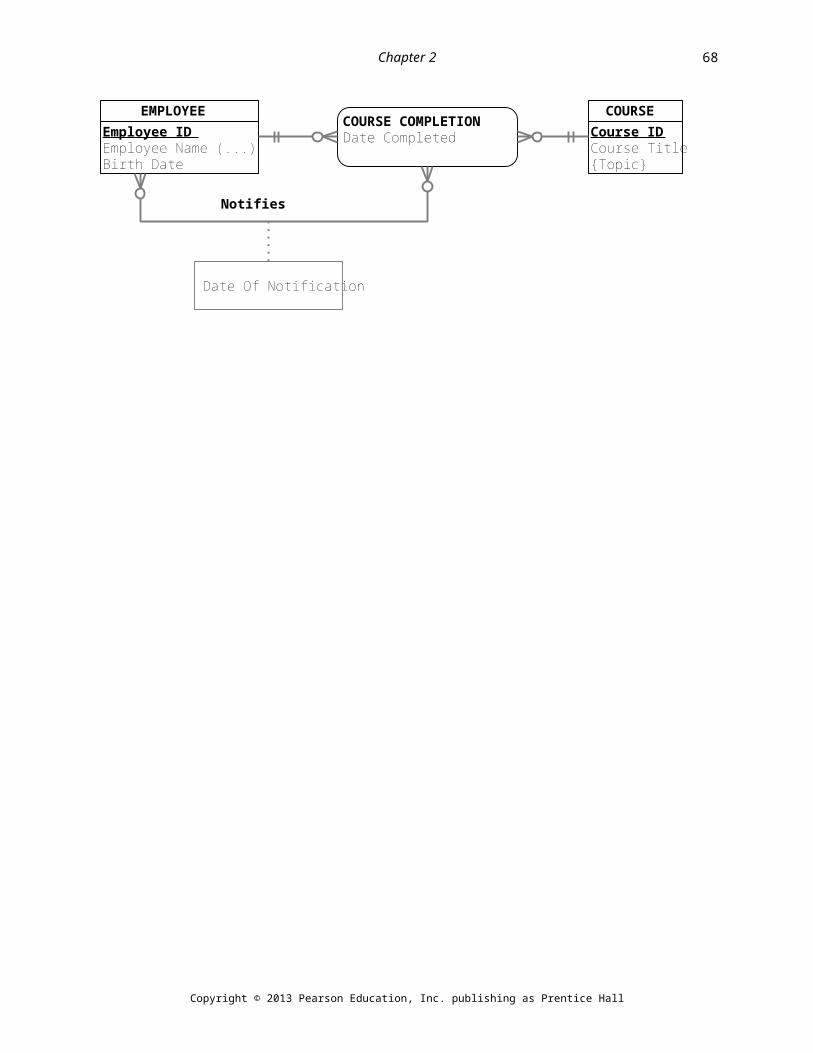
15. Figure 11a (Modified):
EMPLOYEEEmployee IDEmployee Name (...)Birth Date
COURSECourse IDCourse Title{Topic}
COURSE COMPLETIONDate Completed
Notifies
Date Of Notification
Copyright © 2013 Pearson Education, Inc. publishing as Prentice Hall
58
Modern Database Management, Eleventh Edition
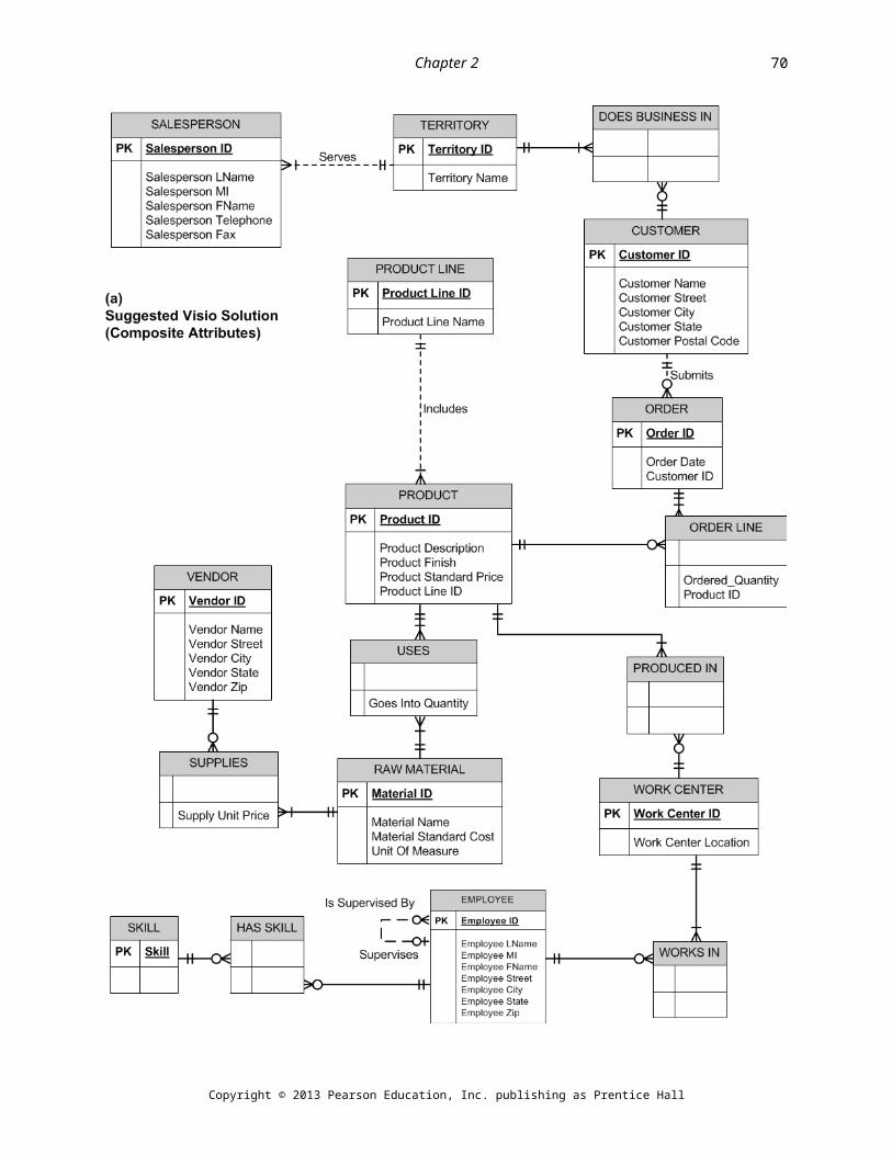
16. a. Salesperson Name (LName, MI, FName), Employee Name (LName, MI, FName)
Copyright © 2013 Pearson Education, Inc. publishing as Prentice Hall
59
Chapter 2
Copyright © 2013 Pearson Education, Inc. publishing as Prentice Hall
60
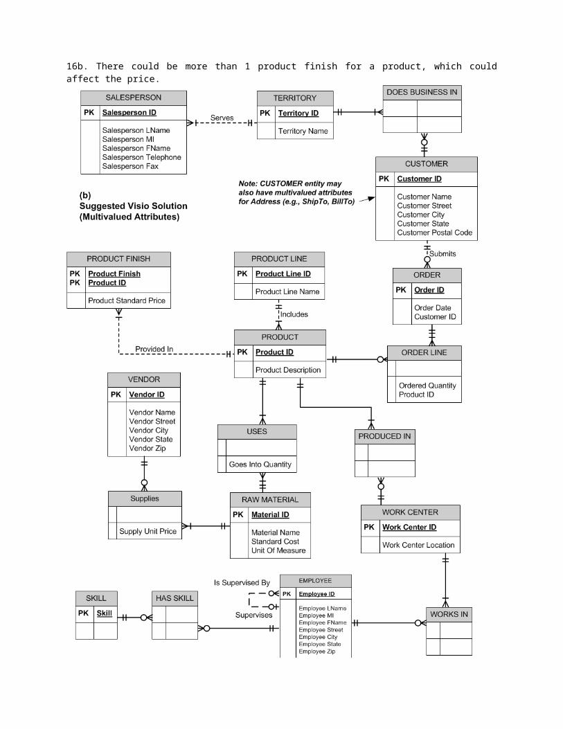
16b. There could be more than 1 product finish for a product, which could affect the price.
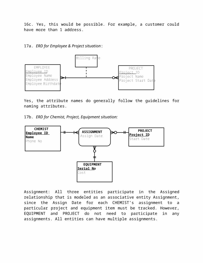
16c. Yes, this would be possible. For example, a customer could have more than 1 address.
17a. ERD for Employee & Project situation:
EMPLOYEEEmployee IDEmployee NameEmployee AddressEmployee Birthdate
PROJECTProject IDProject NameProject Start Date
Billing Rate
Yes, the attribute names do generally follow the guidelines for naming attributes.
17b. ERD for Chemist, Project, Equipment situation:
CHEMISTEmployee IDNamePhone No
EQUIPMENTSerial NoCost
PROJECTProject IDStart Date
ASSIGNMENTAssign Date
Assignment: All three entities participate in the Assigned relationship that is modeled as an associative entity Assignment, since the Assign Date for each CHEMIST’s assignment to a particular project and equipment item must be tracked. However, EQUIPMENT and PROJECT do not need to participate in any assignments. All entities can have multiple assignments.
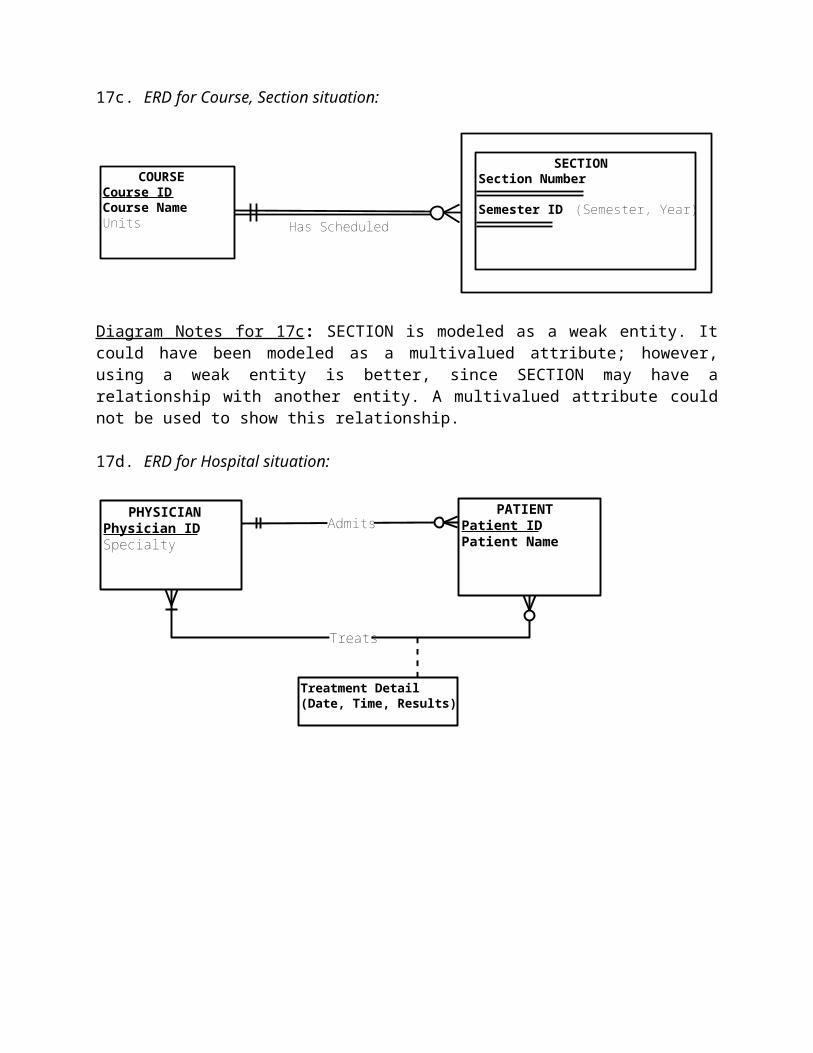
17c. ERD for Course, Section situation:
COURSECourse IDCourse NameUnits
SECTIONSection Number
Semester ID (Semester, Year)Has Scheduled
Diagram Notes for 17c: SECTION is modeled as a weak entity. It could have been modeled as a multivalued attribute; however, using a weak entity is better, since SECTION may have a relationship with another entity. A multivalued attribute could not be used to show this relationship.
17d. ERD for Hospital situation:
PHYSICIANPhysician IDSpecialty
PATIENTPatient IDPatient Name
Admits
Treats
Treatment Detail(Date, Time, Results)
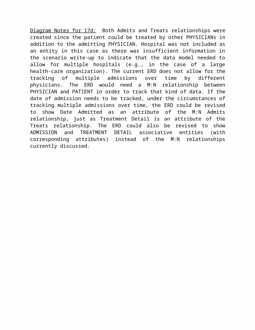
Diagram Notes for 17d: Both Admits and Treats relationships were created since the patient could be treated by other PHYSICIANs in addition to the admitting PHYSICIAN. Hospital was not included as an entity in this case as there was insufficient information in the scenario write-up to indicate that the data model needed to allow for multiple hospitals (e.g., in the case of a large health-care organization). The current ERD does not allow for the tracking of multiple admissions over time by different physicians. The ERD would need a M:N relationship between PHYSICIAN and PATIENT in order to track that kind of data. If the date of admission needs to be tracked, under the circumstances of tracking multiple admissions over time, the ERD could be revised to show Date Admitted as an attribute of the M:N Admits relationship, just as Treatment Detail is an attribute of the Treats relationship. The ERD could also be revised to show ADMISSION and TREATMENT DETAIL associative entities (with corresponding attributes) instead of the M:N relationships currently discussed.
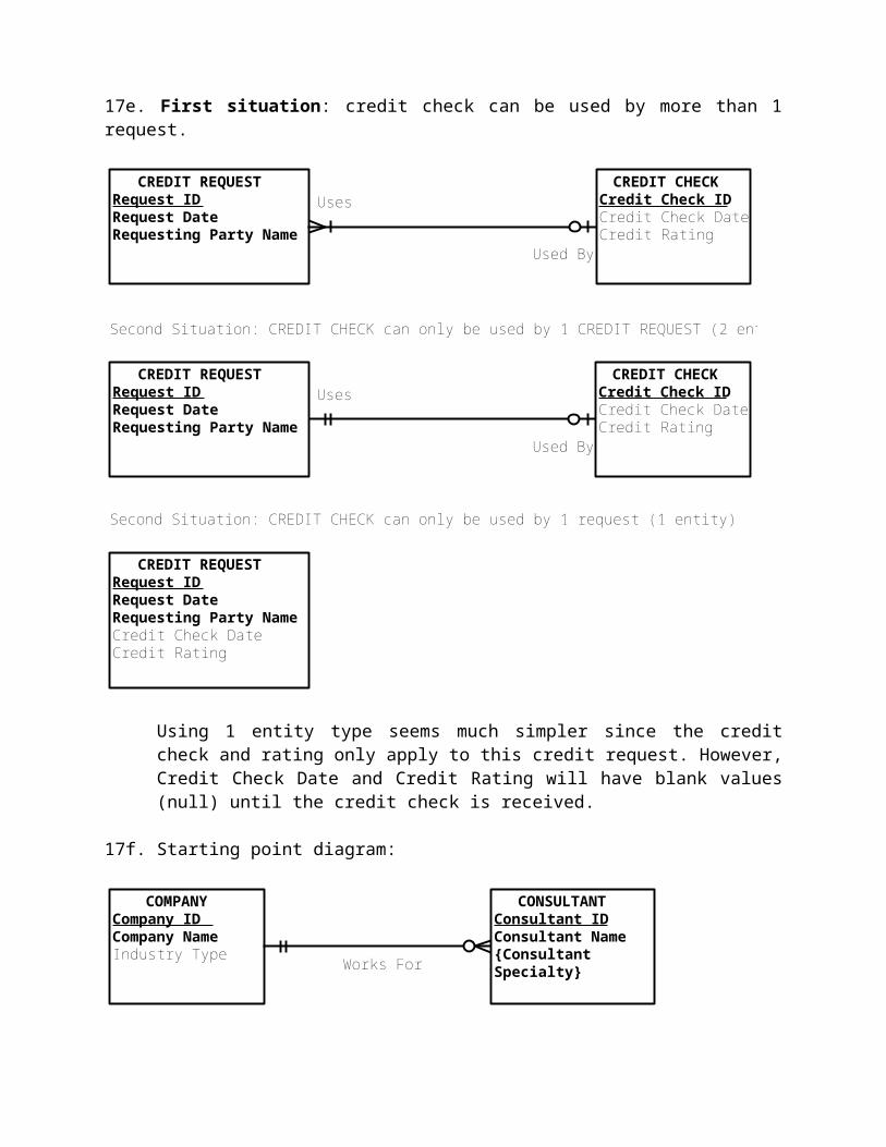
17e. First situation: credit check can be used by more than 1 request.
CREDIT REQUESTRequest IDRequest DateRequesting Party Name
CREDIT CHECKCredit Check IDCredit Check DateCredit Rating
Uses
Used By
CREDIT REQUESTRequest IDRequest DateRequesting Party Name
CREDIT CHECKCredit Check IDCredit Check DateCredit Rating
Uses
Used By
Second Situation: CREDIT CHECK can only be used by 1 CREDIT REQUEST (2 entities)
Second Situation: CREDIT CHECK can only be used by 1 request (1 entity)
CREDIT REQUESTRequest IDRequest DateRequesting Party NameCredit Check DateCredit Rating
Using 1 entity type seems much simpler since the credit check and rating only apply to this credit request. However, Credit Check Date and Credit Rating will have blank values (null) until the credit check is received.
17f. Starting point diagram:
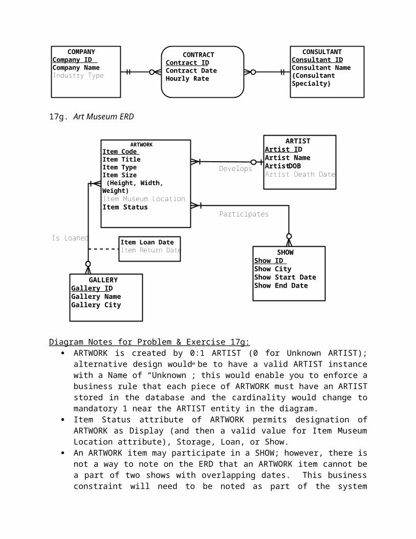
COMPANYCompany IDCompany NameIndustry Type
CONSULTANTConsultant IDConsultant Name{ConsultantSpecialty}Works For
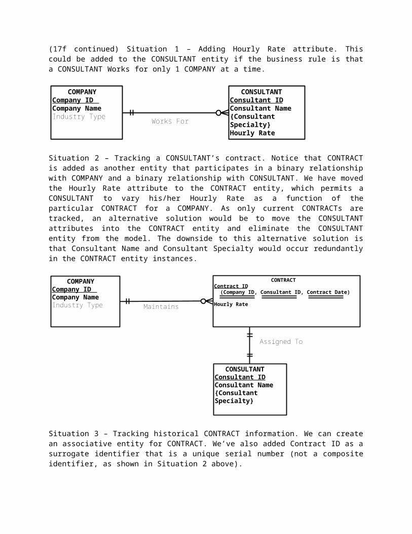
(17f continued) Situation 1 – Adding Hourly Rate attribute. This could be added to the CONSULTANT entity if the business rule is that a CONSULTANT Works for only 1 COMPANY at a time.
COMPANYCompany IDCompany NameIndustry Type
CONSULTANTConsultant IDConsultant Name{ConsultantSpecialty}Hourly Rate
Works For
Situation 2 – Tracking a CONSULTANT’s contract. Notice that CONTRACT is added as another entity that participates in a binary relationship with COMPANY and a binary relationship with CONSULTANT. We have moved the Hourly Rate attribute to the CONTRACT entity, which permits a CONSULTANT to vary his/her Hourly Rate as a function of the particular CONTRACT for a COMPANY. As only current CONTRACTs are tracked, an alternative solution would be to move the CONSULTANT attributes into the CONTRACT entity and eliminate the CONSULTANT entity from the model. The downside to this alternative solution is that Consultant Name and Consultant Specialty would occur redundantly in the CONTRACT entity instances.
COMPANYCompany IDCompany NameIndustry Type
CONTRACTContract ID (Company ID, Consultant ID, Contract Date)
Hourly Rate
CONSULTANTConsultant IDConsultant Name{ConsultantSpecialty}
Assigned To
Maintains
Situation 3 – Tracking historical CONTRACT information. We can create an associative entity for CONTRACT. We’ve also added Contract ID as a surrogate identifier that is a unique serial number (not a composite identifier, as shown in Situation 2 above).
COMPANYCompany IDCompany NameIndustry Type
CONTRACTContract IDContract DateHourly Rate
CONSULTANTConsultant IDConsultant Name{ConsultantSpecialty}
17g. Art Museum ERD
ARTWORKItem CodeItem TitleItem TypeItem Size (Height, Width,Weight)Item Museum LocationItem Status
ARTISTArtist IDArtist NameArtist DOBArtist Death Date
Develops
GALLERYGallery IDGallery NameGallery City
SHOWShow IDShow CityShow Start DateShow End Date
Is Loaned Item Loan DateItem Return Date
Participates
Diagram Notes for Problem & Exercise 17g: ARTWORK is created by 0:1 ARTIST (0 for Unknown ARTIST); alternative design
would be to have a valid ARTIST instance with a Name of “Unknown”; this would enable you to enforce a business rule that each piece of ARTWORK must have an ARTIST stored in the database and the cardinality would change to mandatory 1 near the ARTIST entity in the diagram.
Item Status attribute of ARTWORK permits designation of ARTWORK as Display (and then a valid value for Item Museum Location attribute), Storage, Loan, or Show.
An ARTWORK item may participate in a SHOW; however, there is not a way to note on the ERD that an ARTWORK item cannot be a part of two shows with overlapping dates. This business constraint will need to be noted as part of the system design documentation.
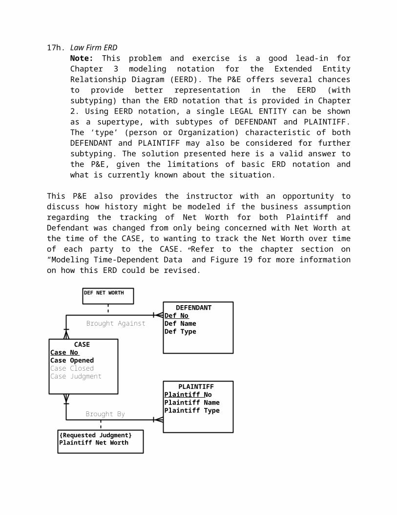
17h. Law Firm ERDNote: This problem and exercise is a good lead-in for Chapter 3 modeling notation for the Extended Entity Relationship Diagram (EERD). The P&E offers several chances to provide better representation in the EERD (with subtyping) than the ERD notation that is provided in Chapter 2. Using EERD notation, a single LEGAL ENTITY can be shown as a supertype, with subtypes of DEFENDANT and PLAINTIFF. The ‘type’ (person or Organization) characteristic of both DEFENDANT and PLAINTIFF may also be considered for further subtyping. The solution presented here is a valid answer to the P&E, given the limitations of basic ERD notation and what is currently known about the situation.
This P&E also provides the instructor with an opportunity to discuss how history might be modeled if the business assumption regarding the tracking of Net Worth for both Plaintiff and Defendant was changed from only being concerned with Net Worth at the time of the CASE, to wanting to track the Net Worth over time of each party to the CASE. Refer to the chapter section on “Modeling Time-Dependent Data” and Figure 19 for more information on how this ERD could be revised.
Brought By
{Requested Judgment}Plaintiff Net Worth
Brought Against
CASECase NoCase OpenedCase ClosedCase Judgment
DEFENDANTDef NoDef NameDef Type
PLAINTIFFPlaintiff NoPlaintiff NamePlaintiff Type
DEF NET WORTH
Diagram Notes for Problem & Exercise 17h: Def Type and Plaintiff Type are used to denote Person or Organization type of legal
entity. Net Worth of both Plaintiff and Defendant is relevant only at the time of the CASE, thus
are modeled as attributes of the M:N relationships between CASE and PLAINTIFF, DEFENDANT.
17i. Publisher, author, book ERD
PUBLISHERPub NamePub MailingAddressPub Phone
BOOKBook ISBNBook TitleBook PriceBook Nbr Pages
AUTHORAuthor IDAuthor NameAuthor Address
ROYALTYCHECK
Check NoCheck DateCheck Amount
ROYALTYRATE
Publishes Writes
Diagram Note for Problem & Exercise 17i: No checks are written before the first royalty is paid, thus the minimum cardinality is 0 for the Royalty Check Associative Entity.
18. PVFC ERD alternative representation
COMPONENTComp NumberComp DescComp Unit Measure
Is Comprised Of
3
Comp Quantity
Used By
Used In
PRODUCTProduct NumberProduct DescProduct Cost
Used To Make
ProductQuantity
Diagram Note for Problem & Exercise 18: A COMPONENT may be Used To Make 0:M PRODUCTs, as a COMPONENT may be a raw material that is not used immediately in making a PRODUCT.

19. Emerging Electric ERD CUSTOMER
Customer IDCustomer NameCustomer Addr(Street, City, State,ZipCode)Customer Phone
LOCATIONLocation IDLocation TypeLocation Addr(Street, City, State,ZipCode)
RATERate ClassRate Per KWH
Time Of DayIs Charged
Located In
Diagram Notes for Problem & Exercise 19: A RATE may be for one, none, or many LOCATIONs. A LOCATION may have multiple CUSTOMERs. A CUSTOMER may own multiple LOCATIONs.
20. STUDENT and ADVISORs ERD
STUDENTStudent IDStudent NameStudent Major
REGISTRATIONReg SemesterReg Year
COURSECourse IDCourse TitleCourse Credits
ADVISORAdvisor IDAdvisor NameAdvisor Dept
SemesterYear
Assigned
21. Figure 4a Revised for Sarbanes-Oxley compliance purposes
ACCOUNT EXPENSE
OFFICER
REPORTRpt Production DateRpt Signoff Date
Is Charged
22. Real Estate Firm ERD
Is Assigned
Lists
Owns Percent Owned
Manages
EMPLOYEEEmployee IDEmployee Name
SALES OFFICEOffice NumberOffice Location
OWNEROwner IDOwner Name
PROPERTYProperty IDProperty Location(Address, City, State,Zip Code)
Diagram Note for Problem & Exercise 22: An additional business rule for this scenario is that an EMPLOYEE may Manage only the SALES OFFICE to which s/he Is Assigned.

22. (continued)
Entities:Employee: An employee of the firm. An employee works for one sales office and may
manage one sales office. It is not explicitly indicated that the employee can only manage the office that he/she works for. This would require a business rule.
Sales Office: The office where real estate is sold.
Property: Buildings for sale, such as houses, condos and apartment buildings.
Owner: The individual who owns one or more properties.
Attributes on Employee:Employee ID: A unique identifier for an employee. This attribute must be unique.Employee Name: The name of the employee.
Attributes on Sales Office:Office Number: A unique identifier for the office.Office Location: The physical location of the sales office. This data may be made up of
the city and state.
Attributes on Property:Property ID: The unique identifier for the property.Property Location: A composite attribute that consists of the street address, city, state,
and Zip Code.
Attributes on Owner:Owner ID: The unique identifier for the owner.Owner Name: The name of the owner.
Relationship:Is Assigned: An employee is assigned to one sales office. A sales office may have many
employees assigned but must have at least one employee.
Manages: An employee may manage one sales office or no sales office. Each sales office is managed by one employee. A business rule is needed here in order to indicate that an employee can only manage the sales office in which he or she works.
Lists: Each property is listed by only one sales office. Each sales office can list one, none, or many properties.
Owns: Each property has one or more owners. Each owner can own one or more properties. Percent Owned is an attribute on Owns; it tracks the percent of property that a particular owner owns.
23. Preliminary ERD for Symphony Orchestra
CONCERT SEASONSeason Open Date(Year, Month, Day)
CONCERTConcert Number{Concert Date(Time, Year, Month, Day)}
COMPOSITIONComposition ID(Composer Name,Composition Name){Movement ID(Movement Name,Movement Number)}
SOLOISTSoloist IDSoloist Name
CONDUCTORConductor IDConductor Name
PERFORMANCE
Schedules
Conducts
{Date Last Performed}
Business Rule: A concert includes the performance of one or more compositions; a composition may be performed at one or more concerts or may not be performed. This business rule is modeled in the ERD above through the use of the COMPOSITION and CONCERT entities, together with the PERFORMANCE Associative Entity.
Note: The use of the Associative Entity PERFORMANCE also permits the independent binary relationship between SOLOIST and PERFORMANCE, which permits the model to support the tracking of derived data, Date Last Performed. Although the diagram appears to have a ternary relationship among COMPOSITION, CONCERT, SOLOIST and PERFORMANCE, such a ternary relationship would not support the requirements of the problem. Rather, the needs of the problem state that there is an overall M:N binary relationship between SOLOIST and PERFORMANCE, which permits the tracking of multiple soloists performing any given composition as well as a given soloist performing multiple compositions.
24. Note: Student answers to this problem and exercise will vary based on their life experiences (e.g., do the students actually receive and review monthly/annual credit card statements), the
drawing tool used, and the documents chosen. Three alternative solutions are presented and are ordered from the least complex to the most complex scenario. The purpose of this problem and exercise is to begin sensitizing students to the occurrence of synonyms and homonyms when ERDs are created. The actual topic does not show up until Chapter 4, but this problem and exercise can be a good lead-in for this discussion.
ERD and analyses for common user views:
Alternative One: 24a
Problem & Exercise Alternative One, Part aAmerican ExpressMonthly Statement of Account ERD - initial draft
CUSTOMERCustomer IDCustomer LastCustomer MICustomer FirstCustomer Street AddrCustomer CityCustomer StateCustomer ZipCustomer PhoneCustomer Email
CARD ACCOUNTAccount NoAcct Exp DateAcct Card Type
ACTIVITYActivity IDActivity DateActivity Post DateActivity TypeActivity Desc(Merchant Name,Merchant State,Merchant Phone,Charge Desc)Activity Amount
Holds
Generates
Notes:1) Acct Card Type refers to Standard, Gold, Platinum, Corporate.2) Activity Type refers to Purchase or Payment.3) Activity Desc is modeled as a composite attribute so that we don't forget to show the details of the Merchant contact information in an Activity instance in the database.
Alternative One: 24b
CUSTOMERCustomer_IDCustomer_Name (Last, MI , First)Customer_Address (Street, City,State, Zip)Customer_PhoneCustomer_Email
ACCOUNTAccount NoAcct Exp DateAcct Card Type
TRANSACTIONTxn IDTxn DateTxn Post DateTxn DescTxn ChargeAmount
Owns
Incurs
Notes:1) Acct Card Type refers to Standard, Gold, Platinum, Corporate.2) SPENDING CATEGORY provides major grouping of ACCOUNT transactions so the CUSTOMER can know spending patterns by groups such as TRAVEL, AUTO, etc. Each SPENDING CATEGORY includes at least one, and usually more than one, SUBCATEGORY. SUBCATEGORIES are unique to each SPENDING CATEGORY.3) TxnDesc includes the 40 character text description of each Merchant's charge to the ACCOUNT.
Problem & Exercise Alternative One, Part bAmerican ExpressYear-End Summary ERD - initial draft
SPENDING SUBCATEGORYSubcategory IDSubcategory Name
SPENDING CATEGORYSpending Category IDSpending CategoryName
Includes
Assigned
Alternative One: 24c
Do you find the same entities, attributes, and relationships in the two ERDs you developed for parts a and b? What differences do you find in modeling the same data entities, attributes, and relationships between the two ERDs? Can you combine the two ERDs into one ERD for which the original two are subsets? Do you encounter any issues in trying to combine the ERDs? Suggest some issues that might arise if two different data modelers had independently developed the two data models.
Yes, the same entity of CUSTOMER is present in both sets of ERDs; this entity also appears to share the same attributes in each ERD version. CARD ACCOUNT in part (a) appears to be the same entity as ACCOUNT in part (b), as the attributes have the same names. The relationship between CUSTOMER and CARD ACCOUNT in the part (a) ERD is Owns, while in the part (b) ERD it is Holds. This would appear to be the same kind of relationship between entity instances in both ERDs. Also, the TRANSACTION entity in part (b) appears to be the same as ACTIVITY in part (a).
There appear to be differences in the level of detail that is modeled in the ACTIVITY entity with respect to the description of the activity charge when it is compared to the TRANSACTION entity’s Txn Desc attribute. Additionally, the part (b) ERD shows additional entities of SPENDING SUB CATEGORY and SPENDING CATEGORY that are related to TRANSACTION; these additional entities are not in evidence in the part (a) ERD.
It would appear that these two ERDs can be combined into one ERD with minimal confusion. However, further clarification from the end user is necessary to determine the meaning (semantics) of the Activity Type attribute in the part (a) ERD and the Txn Desc attribute in the part (b) ERD. Further, some discussion is necessary to determine whether the use of “Activity” or “Transaction” terminology is preferred with the end users so proper decisions can be made about attribute naming conventions.
If two data modelers had independently modeled these user views, it is possible that even greater variance might be evidenced between the entity, attribute, and relationship names. It is also possible that the data modeler working on the Monthly Statement user view might not have been as specific in noting the composition of the Activity Desc attribute; thus, it would not be apparent that contact information related to the Merchant is part of this data model.
Alternative One: 24dHow might you use data naming and definition standards to overcome the issues you identified in part c?
Naming and definition standards could be used to develop common Classes [e.g., Identifier (ID), Number (No), Date (Date), Address (Addr), Transaction (Txn), Description (Desc)] and Qualifiers [Post, Transaction, Activity].

Alternative Two: 24a
MERCHANTMerchant IDMerchant NameMerchant Addr (Street, City, State,Zip)Merchant Phone
RECEIPTReceipt NoRct DateRct TimeRct Transaction TypeRct CC Charge AmountRct CC Account NoRct CC Card TypeRct CC Auth Code
Issues
Problem & Exercise Alternative Two Part aCredit Card Receipt ERD - first draft
Notes:1) Rct Transaction Type refers to Sale or Refund; a RECEIPT has only 1 Rct Transaction Type at a time.2) This ERD refers to a Credit Card Receipt; revisions would be necessary to depict a cash transaction.3) Rct CC Card Type refers to Visa, MasterCard, American Express, Discover, etc.
Alternative Two: 24b
Problem & Exercise Alternative Two Part bMonthly Statement of Visa Credit Card Account ERD - first draft
ACCOUNTAccount NoAcct Credit LineAcct Cash AdvLimitAcct StatusAcct Bill CycleDaysAcct Bill Cycle DateAcct Exp DateAcct Current Bal
TRANSACTIONTxn IDTxn DateTxn Post DateTxn TypeTxn Amount
TXN CATEGORYTxn Cat CodeTxn CatDescription
CHG TO CATEGORYChg To Cat CodeChg To CatDescription
Incurs
Is Assigned
Is Provided
CUSTOMERCust NoCust Name (Last, MI,First)Cust Address (Street, City, State, Zip)Cust PhoneCust Approval Date
Owns
MERCHANTMerchant NoMerchant NameMerchant Address(Street, City, State, Zip)Merchant PhoneMerchant Txn TextMerchant Approval Date
Paid to
Diagram Notes to Problem & Exercise Alternative Two, 24b: Txn Type refers to Purchase, Cash Advance, Payment, or Adjustment. CHG TO CATEGORY refers to Finance Charge Categories (e.g., Standard Purchase or
Standard Cash Adv). TXN CATEGORY refers to Spending Categories (e.g., Merchandise, Services, Auto
Rental, etc.). Acct Status refers to Active, Inactive, Closed, and Overdue. Merchant Txn Text refers to the text shown as part of the Txn Description shown on the
Monthly Summary; if this value is NULL, then the business rule is to show Merchant Name, Merchant City, Merchant State as part of the Transaction Description information on the Monthly Summary report.
Alternative Two: 24c
Do you find the same entities, attributes, and relationships in the two ERDs you developed for parts a and b? What differences do you find in modeling the same data entities, attributes, and relationships between the two ERDs? Can you combine the two ERDs into one ERD for which the original two are subsets? Do you encounter any issues in trying to combine the ERDs? Suggest some issues that might arise if two different data modelers had independently developed the two data models.
Yes, when comparing the ERDs in part (a) and part (b), MERCHANT appears to be the same entity in both data models. Additionally, since it is known that the physical Receipt document that was used to generate the part (a) ERD is actually one of the transactions that is shown on the Visa Monthly Statement, there are common attributes between RECEIPT (part a) and TRANSACTION (part b), although different names have been used in the data models. Additionally, the Rct CC Account No from RECEIPT (in part a) is equivalent to the Account No from ACCOUNT (in part b).
The two ERDs could be combined into one ERD, however, there would need to be decisions made about how the data that crosses organizational boundaries are maintained in different organization’s databases. For instance, the Receipt No on the Merchant’s receipts for purchases at the Merchant are relevant to the Merchant’s internal accounting records and may not be of use to the Credit Card Company’s reporting to its account cardholders. Likewise, the Credit Card Company needs to track the date that a particular account transaction is posted to the account, and this level of data is most likely not of interest to the Merchant.
Aside from this larger issue, there are some minor naming issues that will need to be overcome if the data models are combined. Even though the MERCHANT entities are the same, standardization on names for the attributes needs to be resolved (e.g., Merchant ID vs. Merchant No). Additionally, the business usage of Transactions versus Receipt language needs to be sorted out.
If two different data modelers had developed these ERDs, there would likely be even more variance in how the names of Entities, Attributes, and Relationships would have been established. It’s also possible that the different data modelers would not recognize that the RECEIPT and TRANSACTION entities are similar, if they did not share the sample data from each separate user view with each other.
Alternative Two: 24dHow might you use data naming and definition standards to overcome the issues you identified in part c?
Naming and definition standards could be used to develop common Classes [e.g., Number (No), Credit Card (CC), Date (Date), Address (Addr), Transaction (Txn), Description (Desc)] and Qualifiers [Post, Transaction, Activity, Billing Cycle], as well as how attribute names will be selected (i.e., Merchant ID vs. Merchant No).
Alternative Three: 24a
STOREStore NoStore NameStore Addr (Street, City, State,Zip)Store Phone
RECEIPTReceipt NoRct DateRct TimeRct Register NoRct Transaction TypeRct CashierRct Line Items SubtotalRct Total TaxRct Purchase TotalRct CC Charge AmountRct CC Account NoRct CC Card TypeRct CC Auth Code
Issues
Problem & Exercise - Alternative Three, Part (a)Cash Register Credit Card Receipt ERD - first draft
ITEMItem NoItem DescItem SizeItem SubSizeItem ColorItem Price
Line ItemLine Item SeqNo
Line QuantityLine Subtotal
Diagram Notes to Problem & Exercise Alternative Three, 24a:
Rct Transaction Type refers to Sale or Refund; a RECEIPT has only 1 Rct Transaction Type at a time.
This ERD refers to a Credit Card Receipt; revisions would be necessary to depict a cash transaction.
Rct Cashier refers to the first name of the Rct Cashier and is assumed to be unique. An alternative design would be to use a Rct Cashier Number and provide a relationship to a CASHIER entity.
Rct CC Card Type refers to Visa or MasterCard. Line Item SeqNo is a partial identifier of the Line Item associative entity; Receipt No and

Item No will be needed to provide a full identifier for each Line Item instance.
Alternative Three: 24b
ACCOUNTAccount NoAcct Credit LineAcct Cash AdvLimitAcct StatusAcct Bill Cycle DaysAcct Bill Cycle DateAcct Exp DateAcct Current Bal
TRANSACTIONTxn IDTxn DateTxn Post DateTxn TypeTxn Amount
TXN CATEGORYTxn Cat CodeTxn CatDescription
CHG TO CATEGORYChg To Cat CodeChg To CatDescription
Incurs
Is Assigned
Is Provided
CUSTOMERCust NoCust Name (Last, MI,First)Cust Address (Street, City, State, Zip)Cust PhoneCust Approval Date
Owns
Problem & Exercise Alternative Three, Part bMonthly Statement of Visa Credit Card Account - first draft
MERCHANTMerchant NoMerchant NameMerchant Address(Street, City, State, Zip)Merchant PhoneMerchant Txn TextMerchant Approval Date
Paid to
Diagram Notes to Problem & Exercise Alternative Three, 24b:
Txn Type refers to Purchase, Cash Advance, Payment, or Adjustment. CHG TO CATEGORY refers to Finance Charge Categories (e.g., Standard Purchase or
Standard Cash Adv). TXN CATEGORY refers to Spending Categories (e.g., Merchandise, Services, Auto
Rental, etc.). Acct Status refers to Active, Inactive, Closed, and Overdue. Merchant Txn Text refers to the text shown as part of the Txn Description shown on the
Monthly Summary; if this value is NULL, then the business rule is to show Merchant Name, Merchant City, Merchant State as part of the Transaction Description information on the Monthly Summary report.
Alternative Three: 24c
Do you find the same entities, attributes, and relationships in the two ERDs you developed for parts a and b? What differences do you find in modeling the same data entities, attributes, and
relationships between the two ERDs? Can you combine the two ERDs into one ERD for which the original two are subsets? Do you encounter any issues in trying to combine the ERDs? Suggest some issues that might arise if two different data modelers had independently developed the two data models.
The Cash Register Credit Card Receipt ERD was developed from a user view of the Customer purchasing items from a Store, and reflects the entities and attributes present on that user view and sample data available in the actual user document. This data model will provide the Customer with a receipt including details of what was purchased, the quantity of the item purchased, the price for each item purchased, as well as tax and the total charge to the credit card account. From the Store’s perspective, this data model provides tracking of the Cashier and Register related to the overall sales transaction, as well as credit card processing information (e.g., type of card, charge amount, card account number, and authorization code), and information related to management of the Store’s inventory (e.g., item information and quantities).
The Monthly Statement of a Visa Credit Card Account ERD was developed from a user view sent to the Account Owner of the Visa Credit Card and reflects the entities and attributes present in the data on the sample document. This data model serves both the Account Owner by providing details of all transactions posted against the Credit Card Account, and also the Visa Credit Card Company by providing transaction charges for both customers and merchants served.
When these two ERDs are reviewed, it does not appear that any entities, attributes, or relationships are named the same which seems to indicate that none of these data model elements are the same between the two ERDs. However, since both the receipt and the monthly statement are for my own purchases with a credit card, it is known that some of the data underlying both of these data models are the same, although different names have been used. For instance, the monthly statement shows a listing of individual credit card receipts. Although in this case, the individual receipt shows more detail than is shown on the monthly statement, it can be seen that the underlying data is the same. The STORE entity in part (a) is actually equivalent to the MERCHANT entity in part (b). The Rct CC Charge Amount and Rct Date attributes (from RECEIPT) in part (a) are the same as the Txn Amount and Txn Date attributes (from TRANSACTION) in part (b). Finally, the Rct CC Account No (from RECEIPT) in part (a) is equivalent to the Account No (from ACCOUNT) in part (b).
Although it is technically feasible to combine these two ERDs into one ERD, it would not be advisable due to the difference in the level of detail captured (e.g., Store Inventory Management data in part a) in the two models and due to the different purposes (and ultimate end users) of the data. Naming standards would also have to be developed to accomplish the merging of the data models. If two data modelers had developed these ERDs, it is unlikely that the common underlying data would have been identified.
Alternative Three: 24dHow might you use data naming and definition standards to overcome the issues you identified in part c?

Naming and definition standards could be used to develop common Classes [e.g., Number (No), Credit Card (CC), Date (Date), Address (Addr), Transaction (Txn), Description (Desc)] and Qualifiers [Post, Transaction, Activity, Billing Cycle]. However, these standards would not address the level of detail and purpose issues identified earlier as issues in merging the ERDs.
25. Projects, Inc. ERD
PROJECTProj NoProj Est Cost
LOCATIONLoc IDLoc CityLoc StateLoc Population
EMP SKILL
DEPARTMENTDept NameDept Phone
VENDORVendor IDVendor NameVendor Address
Date Last Meeting
Buys From
Assigned To
Belongs ToSKILL
Skill NoSkill Description
Is Married To
DateMarried
EMPLOYEEEmp NoEmp NameEmp TitleEmp Date Of Birth
Diagram Notes for Projects, Inc. Problem & Exercise 25: We assume that a Vendor will be tracked in our database even if they have not participated
in a Buys From relationship with a department, hence, the 0:M cardinality next to Department in the diagram. This permits the tracking of a Vendor in our database prior to the
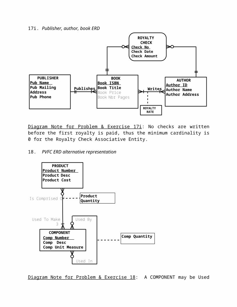
first transaction with us. We assume that we may set up a Department in our company that may not yet have
employees assigned to it; thus, the 0:M cardinality next to Employee on the Belongs To relationship between Employee and Department.
Classes: Number (No), Identifier (ID), Date; Qualifiers: Married, Of Birth, Last Meeting26. Stillwater Antiques ERD
ITEMItem NoItem DescItem Asking PriceItem ConditionItem Comments
CLIENTClient NoClient NameClient Address
Sold To
Bought From
Sales CommissionSales PriceSales TaxSales Date
Purchase CostPurchaseConditionPurchase Date

27. H.I. Topi School of Business ERD
STUDENTStudent NoStudent NameCurrent NameCurrent AddressCountry of BirthCountry Citizenship{Major}
EVENTEvent IDEvent LocationEvent DateEvent TypeEvent Title
CONTACTContact TypeContact DateContact Info
Comment
Note: Contact Type refers to mail, email, telephone, fax, or personal discussion.
Attends
Makes
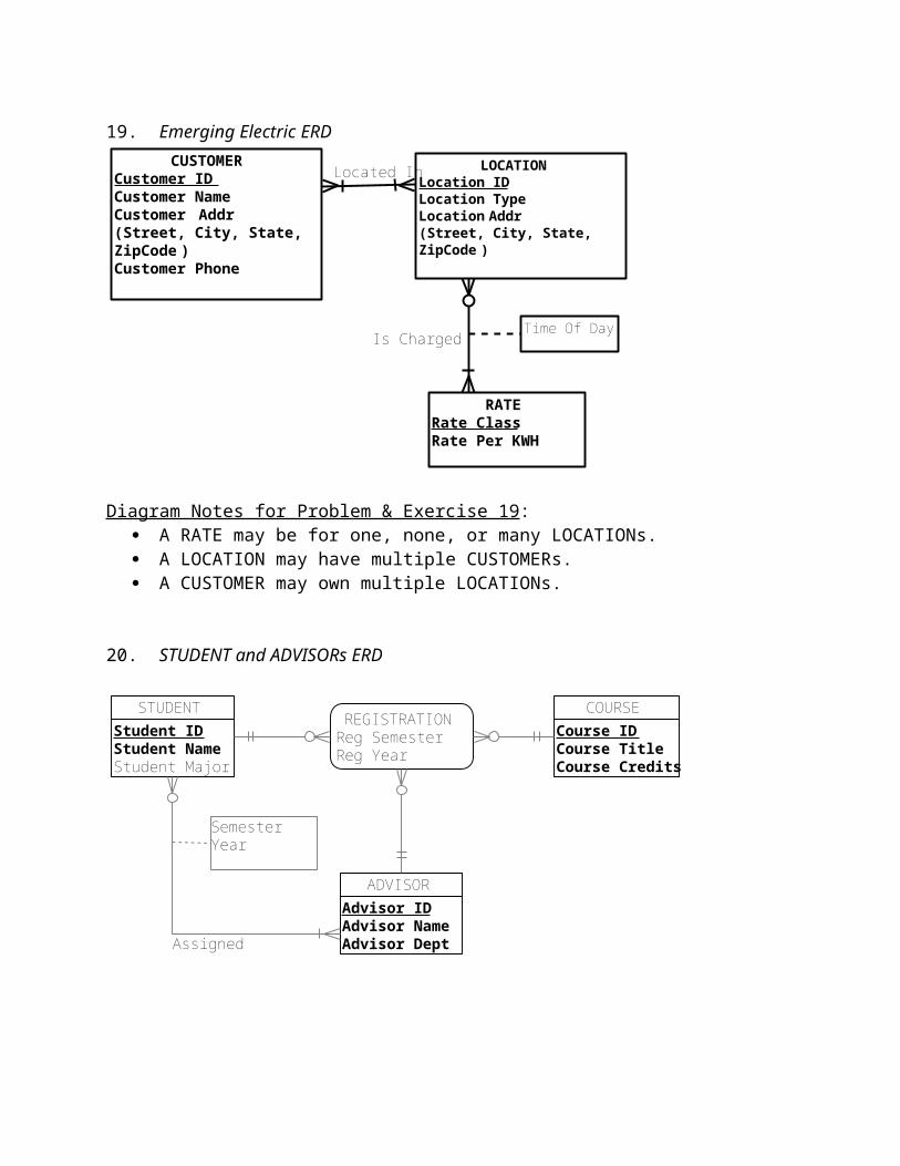
28. Wally’s Wonderful World of Wallcoverings ERD:
EMPLOYEEEmp IDEmp NameEmp Addr(Street, City, State,ZipCode)Emp PhoneEmp TitleEmp Salary{Emp Skill}Emp AgeEmp Hire Date
DEPENDENTDep Name
DepRelationshipDep Age
BRANCHBranch NoBranch Loc(Address, City, State,ZipCode)Square Footage
ITEMItem IDItem DescItem TypeItem PatternItem ColorItem Size
CUSTOMERCust IDCust NameCust Street AddrCust CityCust StateCust Zip CodeCust PhoneCust DOBCust Primary Language
ORDEROrder DateOrder Credit Status
ACCOUNTAccount NoAccount TypeAccount BalanceAccount Payment DateAccount PaymentAmount
Employs
Serves
Note:The question does not indicate that there is a quantity for the Contains or Consists Of relationships.
Carries
Consists Of
Sells
Contains
Owns
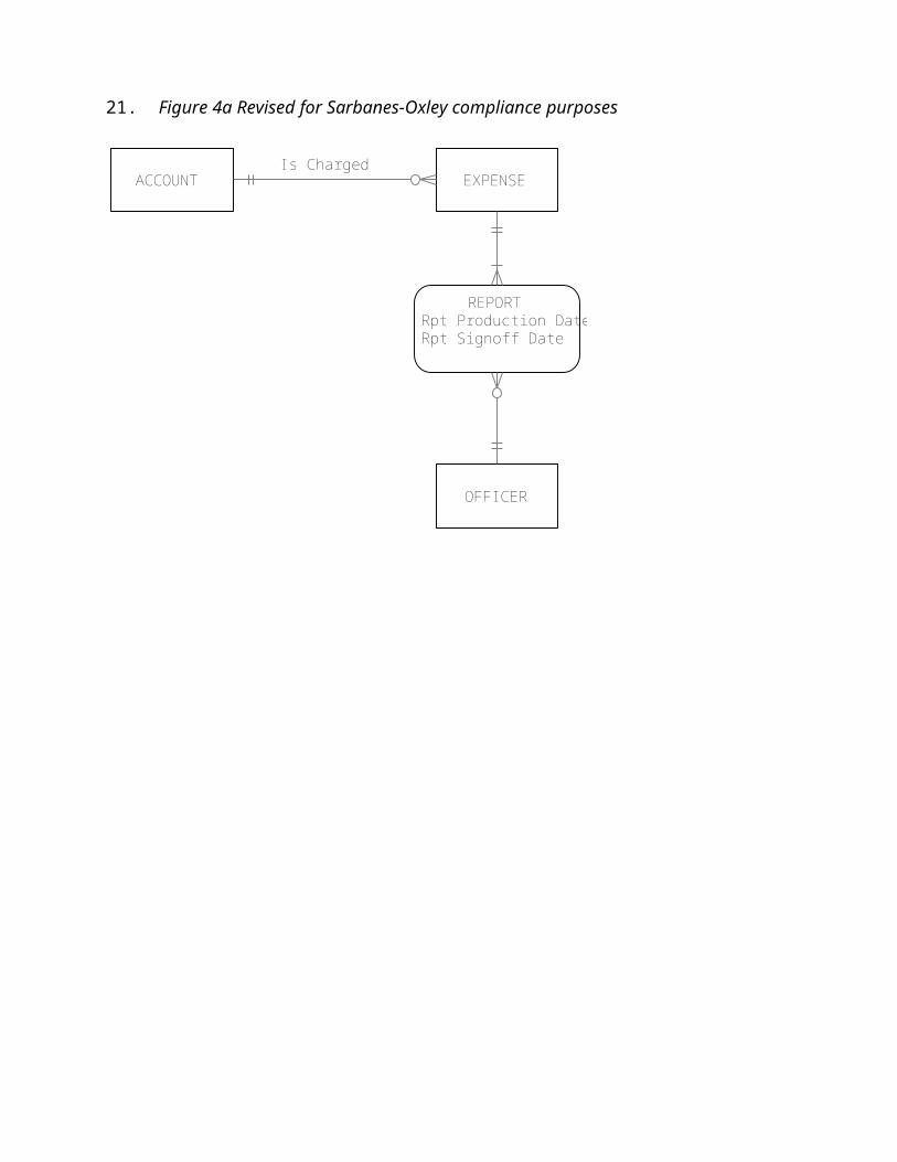
29. Peck and Paw ERD: ATTORNEY
Attorney IDAttorney NameAttorney Str AddrAttorney CityAttorney StateAttorney Zip Code{Attorney Bar}{AttorneySpecialty}
CLIENTClient IDClient NameClient Str AddrClient CityClient StateClient Zip CodeClient PhoneClient DOB
CASECase IDCase TypeCase Desc
COURTCourt IDCourt NameCourt CityCourt StateCourt Zip Code
JUDGEJudge IDJudge NameJudge Yrs In Practice
ASSIGNMENT
Presides Over
Placed In
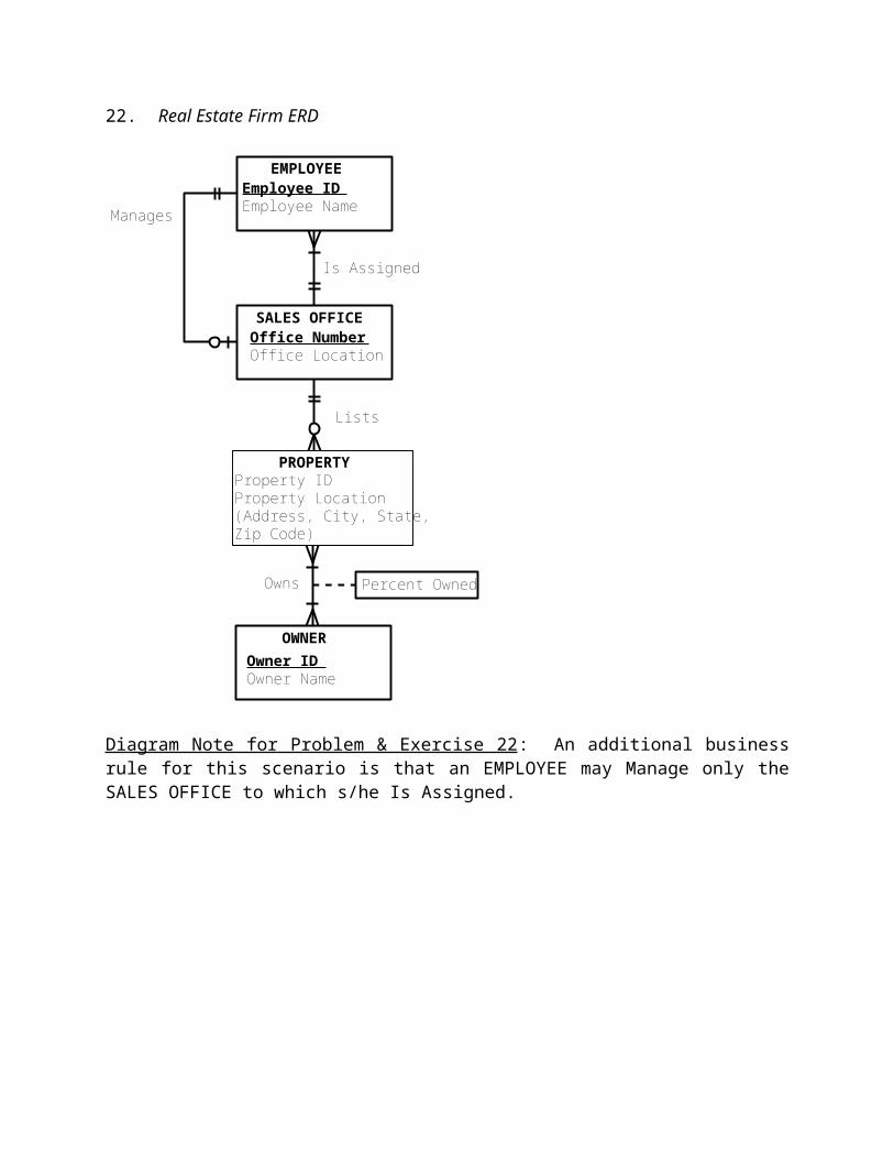
30. Revision to prior ERD in #27
STUDENTStudent NoStudent NameStudent Current NameStudent Current AddressStudent Country Of BirthStudent CountryCitizenship{Student Major}
EVENTEvent IDEvent LocationEvent DateEvent TypeEvent Title
CONTACTContact TypeContact DateContact Info
Comment
Note: Contact Type refers to mail, email, telephone, fax, or personal discussion.
Attends
Makes
Changes made to prior #27 ERD- added qualifiers to attribute names in the STUDENT entity
Entities:Student: A person who attended and graduated from the H.I. Topi School of Business.
Event: School events held around the world.
Contact: The School’s records of any contact made with a former student and graduate of the School.
Attributes on Student:Student No: A unique identifier for a student when they attended the School. This
attribute must be unique and is required.Student Name: The name of the student when attending the School. This attribute is
required.Student Current Name: Current name of the former student.Student Current Address: Current address of the former student.Student Country of Birth: Country where the former student was born.Student Country of Citizenship: Country where the former student holds citizenship.Student Major: The name of the academic major completed by the former student. A
student may have one or two majors. This attribute is required.
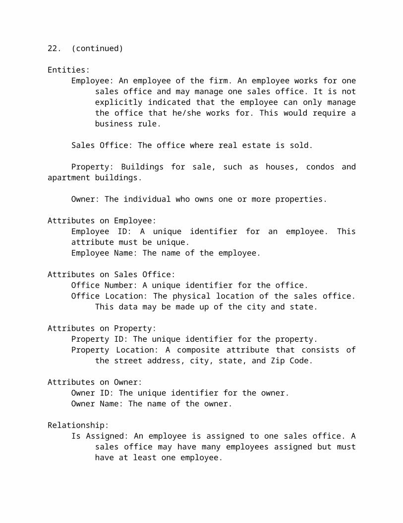
Attributes on Event:Event ID: A unique identifier for the event. This attribute is required.Event Location: The physical location of the event. This data may be made up of the
street address, city, state, postal code, and country.Event Date: The year, month, and day of the event.Event Type: The type of event (e.g., reception, dinner, or seminar).Event Title: The title of the event, as used in the press release and communications with
the former students. This attribute is required.
Attributes on Contact:Contact Type: The category of contact type made with the former student. Possible
values include mail, email, telephone, and fax. This attribute is required.Contact Date: The year, month, and day of the contact event with the former student.
This attribute is required.Contact Info: The updated information about the former student that was learned during
the contact event. This attribute is required.
Relationship:Attends: A student attends zero, one, or many events. An event has one or more students
in attendance.
Makes: The school makes contact with a specific former student. For each contact with a specific student, the School tracks zero, one, or many instances of contact information.
Attributes on Relationship:Comment: Information that school officials learn from a graduate at a specific event.
Suggestions for Field Exercises
1. The intent of this exercise is to have your students gain some exposure to standards in the business world. This is a good opportunity for your students to learn the benefits of enforcing naming standards, whether for E-R models or for programming code. If standards do not exist in the organization, have your students come up with some guidelines for naming standards. If standards do exist, your students should ask the database or systems analyst for an opportunity to review these standards to see if they are consistent and uniform.
2. You may choose to use the same organizations for this field exercise that were used in Chapter 1 Field Exercises, or instead choose different organizations. It is likely that some of your students may have contacts in suitable organizations. The main difference that students are likely to find in a manufacturing company (compared to a service company) is the complexity encountered in modeling a product structure (or bill of materials). This often results in a recursive unary relationship, which is described in this chapter.
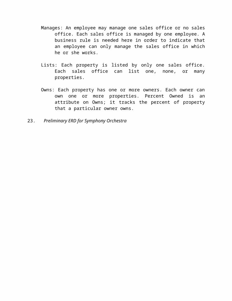
3. This field exercise can be performed in conjunction with Exercise 2 above. Most organizations will probably have examples of each of these types of relationships. Be on the alert to discover ternary relationships that are mistakenly modeled as multiple binary relationships.
4. This field exercise can be combined with Exercise 3 above. It is quite likely the organization will be using E-R notations that are different from the text, but students should be able to accommodate different notations with some explanation.
5. We suggest you combine this with Exercise 4 (and perhaps Exercise 3) above. If time-dependent data is apparent in the models, you might ask, for example, how the organization tracks customer sales over time.
6. Students should build a table to compare features of all products.
Project Case
Case Questions
1. Mountain View Community Hospital (MVCH) would want to use ER modeling to understand its data requirements because this approach will provide a pictorial depiction of MVCH’s business rules about data and how it is managed in the organization. The ER model provides a representation of these rules so they can be understood unambiguously by system developers and end users. The hospital might also want to model their requirements using the object-oriented model (see later chapter in text). Other possible diagrams might be data flow diagrams (DFD), state-transition diagrams, or use case diagrams.
2. No; Mountain View Community Hospital is an instance of the entity type HOSPITAL. Since there is only one instance, there is no need to model the HOSPITAL entity type.
3.a. BED may be a weak entity because it appears to require a Care Center ID attribute
(per case description). MVCH may have a business rule requiring a BED to be assigned to a CARE CENTER in order for the system to track the BED.
b. There are no multivalued attributes.
c. Between PATIENT and PHYSICIAN there are two relationships: Refers and Admits. Between EMPLOYEE and CARE CENTER there are two relationships: Has Assigned and Nurse In Charge.
4. At this stage in our understanding of E-R diagrams, we simply diagram the relationship (called Is Assigned) between PATIENT and BED as an optional 0-1 relationship. In Chapter 3 we will learn how to model the subtypes of PATIENT (INPATIENT and OUTPATIENT) and then create a mandatory relationship between INPATIENT and
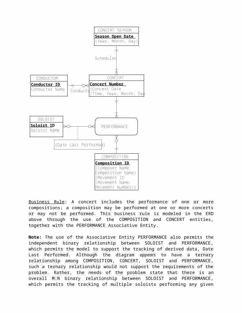
BED.
5. The only reason to split ITEM into two separate entities would be to track the use of reusable items. In other words, once an item is purchased and can be reused, one might want to see how frequently an item is used. In this case, one might wish to record the item serial number (or assign a number) and then see specifically how that item was used. However, I still think that it would be of merit to track reusable items in the general sense. For example, you might want to know that you have 100 forceps in stock. If one gets damaged and is thrown away, the inventory is reduced. Once the inventory reaches a certain level, more forceps can be ordered.
6. Take a look at all user views by examining reports and screens from any existing systems. Then compare these to the data model and make a determination of whether this data model will support the system’s generation of reports and screens.
Case Exercises
1. Some other questions we might like to ask are the following:a. Should we model pharmaceutical items separately from ITEM since such items
are prescribed by a physician for a patient?b. Is there a need to maintain a historical record of a patient’s relationship with the
hospital? If so, how can this be modeled in the E-R diagram?c. Need we model the various subtypes of EMPLOYEE (nurses, staff, physicians,
etc.)?d. Is there a need to model the relationship with other persons such as volunteers
and donors?You should ask your students to develop additional questions.
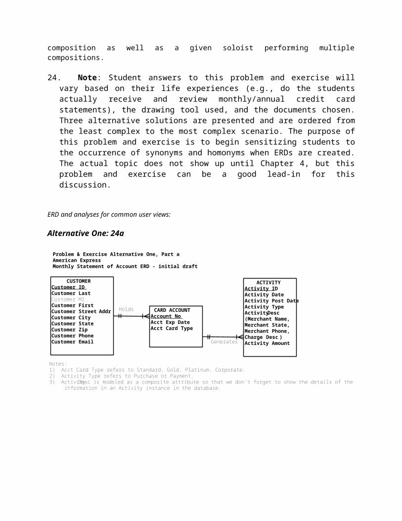
2. ERD for Case Exercise #2
CARE CENTERCare Center IDCare Center Name
EMPLOYEEEmp NoEmp Name
Hours Worked
BEDBed NoRoom No
Is Part Of
PATIENTMRNPatient Name
Is Assigned
ITEM CONSUMPTIONConsume DateConsume TimeConsume Qty[Total Cost]
ITEMItem NoItem DescItem Unit Cost
ASSESSMENTVisit IDVisit DateVisit TimeVisit CommentsVisit Patient WeightVisit Patient BPVisit Patient PulseVisit Patient Temp
PHYSICIANPhysician IDPhysician Name
ORDEROrder IDOrder DateOrder Time
TREATMENTTreatment CodeTreatment Name
Consists Of
Treatment DateTreatment TimeResults
PHYSICIAN DXDiagnosis DateDiagnosis Time
DIAGNOSISDiagnosis CodeDiagnosis Name
Has Assigned
Nurse In Charge
Admits
Refers
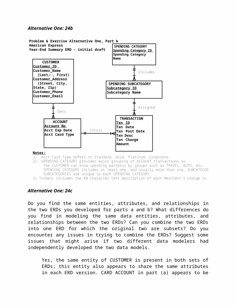
Diagram Notes for Case Exercise 2 (prior page): An EMPLOYEE may serve as a Nurse In Charge for 0, 1, or many CARE CENTERs. Visit ID is unique (surrogate) identifier for ASSESSMENT. Comments attribute for ASSESSMENT is used to record reasons for visit and symptoms.
3. No. The entity type ITEM has a Unit Cost attribute, but has no provision to represent a unit cost per day, which would be required for items such as in-room TVs.
4. Diagram Notes for Case Exercise 4 (diagram on next page): An EMPLOYEE may serve as a Nurse In Charge for 0, 1, or many CARE CENTERs. Visit ID is unique (surrogate) identifier for ASSESSMENT. Comments attribute for ASSESSMENT is used to record reasons for visit and symptoms. Bed ID is surrogate composite identifier for BED; it is shown as a partial identifier as Care
Center ID will be needed to complete the unique identifier and Care Center ID will be added in a later design step.
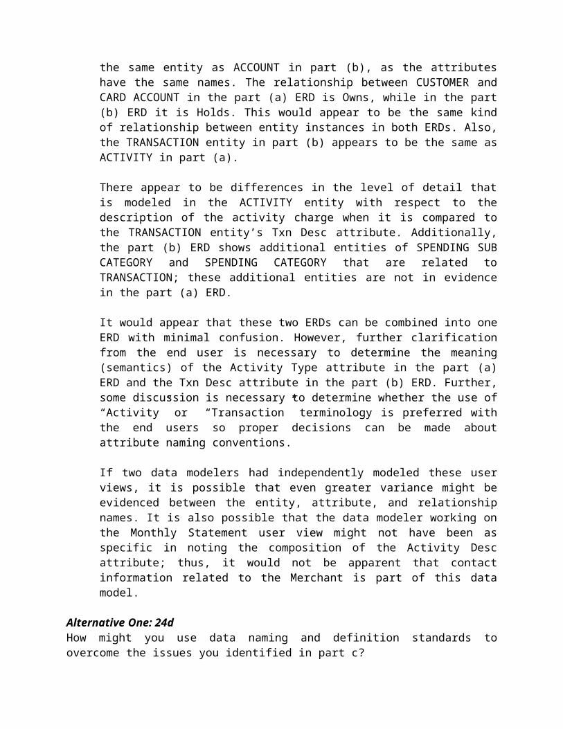
4. ERD for Case Exercise #4
CARE CENTERCare Center IDCare Center Name
EMPLOYEEEmp NoEmp Name
Hours Worked
Is Part Of
PATIENTMRNPatient Name
Is Assigned
ITEM CONSUMPTIONConsume DateConsume TimeConsume Qty[Total Cost]
ITEMItem NoItem DescItem Unit Cost
ASSESSMENTVisit IDVisit DateVisit TimeVisit CommentsVisit Patient WeightVisit Patient BPVisit Patient PulseVisit Patient Temp
PHYSICIANPhysician IDPhysician Name
ORDEROrder IDOrder DateOrder Time
TREATMENTTreatment CodeTreatment Name
Consists Of
Treatment DateTreatment TimeResults
PHYSICIAN DXDiagnosis DateDiagnosis Time
DIAGNOSISDiagnosis CodeDiagnosis Name
BEDBedID
(Room No, BedNo)
Has Assigned
Nurse In Charge
Admits
Refers

5. ERD for Case Exercise #5
CARE CENTERCare Center IDCare Center Name
EMPLOYEEEmp NoEmp Name
Hours Worked
PATIENTMRNPatient Name
Is Assigned
ITEM CONSUMPTIONConsume DateConsume TimeConsume Qty[Total Cost]
ITEMItem NoItem DescItem Unit Cost
ASSESSMENTVisit IDVisit DateVisit TimeVisit CommentsVisit Patient WeightVisit Patient BPVisit Patient PulseVisit Patient Temp
PHYSICIANPhysician IDPhysician Name
ORDEROrder IDOrder DateOrder Time
TREATMENTTreatment CodeTreatment Name
Consists Of
Treatment DateTreatment TimeResults
PHYSICIAN DXDiagnosis DateDiagnosis Time
DIAGNOSISDiagnosis CodeDiagnosis Name
BEDBed ID
(Bed No, RoomNo)
ROOMRoom No
Contained In
Contains
ITEM BILLINGStart DateEnd DateCost
Has Assigned
Nurse In Charge
Admits
Refers
5. Diagram Notes for Case Exercise 5: An EMPLOYEE may serve as a Nurse In Charge for 0, 1, or many CARE CENTERs. Visit ID is unique (surrogate) identifier for ASSESSMENT. Comments attribute for ASSESSMENT is used to record reasons for visit and symptoms. Bed ID is surrogate composite identifier for BED; it is shown as a partial identifier as Room
No will be needed to complete the unique identifier and Room No will be added in a later design step.
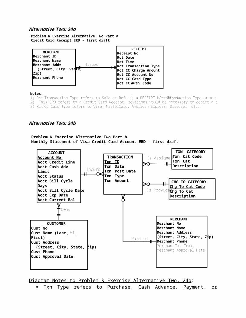
6. Yes. Any combination of patient and treatment has multiple physicians who perform that treatment.
7. Yes. The model records the date, time, and results for each treatment occurrence performed by a physician on behalf of a patient.
Project AssignmentsP1. ER diagram
P2. A FACILITY can contain one or more CARE CENTERS or may contain no CARE
CENTERS. A CARE CENTER is part of one and only one FACILITY.
A FACILITY may maintain one or more DIAGNOSTIC UNITS or may maintain no DIAGNOSTIC UNITS. A DIAGNOSTIC UNIT is part of only one FACILITY.
A CARE CENTER has many EMPLOYEES. Each CARE CENTER has one EMPLOYEE assigned as a nurse in charge. Each EMPLOYEE may work for one or more CARE CENTERS.
A CARE CENTER will contain one or more ROOMs. Each ROOM is contained in only one CARE CENTER.
A ROOM may contain one or more beds or may contain no BEDS, A BED is contained in only one ROOM.
A DIAGNOSTIC UNIT performs one or more TREATMENTS. A TREATMENT is performed by only one DIAGNOSTIC UNIT.
A BED is assigned to one patient or no patients. A PATIENT is assigned to one BED or no BEDS.
A PHYSICIAN admits one or more PATIENTS or admits no PATIENTS. A PATIENT is admitted by only one PHYSICIAN.
A PHYSICIAN may refer one or more PATIENTS or may refer no PATIENTS. A PATIENT must be referred by one PHYSICIAN.
A PATIENT may consume many ITEMS or may consume no ITEMS. An ITEM is consumed by one or more PATIENTS or may be consumed by no PATIENTS.
An ITEM is supplied by one or more VENDORS. A VENDOR may supply one or more ITEMS or may supply no ITEMS.
A PHYSICIAN may write one or more ORDERS or may write no ORDERS for one PATIENT. An ORDER is written by one PHYSICIAN.
An ORDER may consist of one or more ITEMS or no ITEMS. An ITEM may be part of one or more ORDERS or may be part of no ORDERS.
An ORDER may consist of one or more TREATMENTS or no TREATMENTS. A TREATMENT may be part of one or more ORDERS.
A PHYSICIAN may complete one or more DIAGNOSES for one or more PATIENTS. A DIAGNOSIS is completed for one PATIENT by one PHYSICIAN.
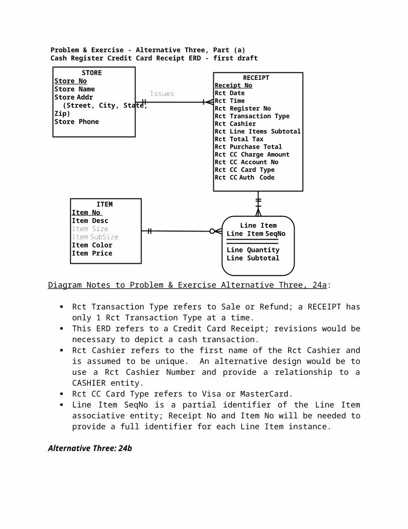
A VENDOR may supply one or more ITEMs. Each ITEM may be supplied by more than one VENDOR.
An EMPLOYEE completes one, none, or many ASSESSMENTs of a PATIENT. Each PATIENT may have one or many ASSESSMENTs over time at this hospital.
A FACILITY may prepare multiple staffing schedules for its PHYSICIANs. Each SCHEDULE instance is for a single FACILITY and a single PHYSICIAN. A PHYSICIAN may have zero, one, or many SCHEDULEs.
P3. Sample questions are listed below; student answers may vary.
a. How is patient billing done?b. What reporting requirements does the administration have?c. Should there be a distinction between a diagnostic test, a procedure, and a
treatment?d. Can a physician choose which diagnostic unit to use for a test?e. How will we handle referrals by physicians who are not on staff?f. How will medical records be modeled? g. Should the relationship between patient and bed contain a start and end date?


![[PPT]Entity – Relationship Model (E-R Model)sivasnscedbms.weebly.com/.../entity__relationship_model.ppt · Web viewEntity – Relationship Model (E-R Model) Entity – Relationship](https://img.pdfslide.net/doc/110x75/5b04acac7f8b9a2d518df0c5/pptentity-relationship-model-e-r-model-viewentity-relationship-model.jpg)