Embed Size (px)
Citation preview

User's Manual
Thank you very much for purchasing this product. To ensure correct and safe usage with a full understanding of this product's performance, please
be sure to read through this manual completely and store it in a safe location. Unauthorized copying or transferral, in whole or in part, of this manual is prohibited. The contents of this operation manual and the specifications of this product are subject to
change without notice. The operation manual and the product have been prepared and tested as much as possible. If
you find any misprint or error, please inform us. Roland DG Corp. assumes no responsibility for any direct or indirect loss or damage which
may occur through use of this product, regardless of any failure to perform on the part of this product.
Roland DG Corp. assumes no responsibility for any direct or indirect loss or damage which may occur with respect to any article made using this product.

For the USA
FEDERAL COMMUNICATIONS COMMIS-SION RADIO FREQUENCY INTERFER-
ENCE STATEMENTNOTE:This equipment has been tested and found to comply with the limits for a Class A digital device, pursuant to Part 15 of the FCC Rules.These limits are designed to provide reasonable protec-tion against harmful interference when the equipment is operated in a commercial environment.This equipment generates, uses, and can radiate radio frequency energy and, if not installed and used in accordance with the instruction manual, may cause harmful interference to radio communications.Operation of this equipment in a residential area is likely to cause harmful interference in which case the user will be required to correct the interference at his own expense.
Unauthorized changes or modification to this system can void the users authority to operate this equipment.
Use only I/O cables that have been designed and manu-factured specifically for this device.
For CanadaNOTICE
This Class A digital apparatus meets all requirements of the Canadian Interference-Causing Equipment Regula-tions.
AVISCet appareil numérique de la classe A respecte toutes les exigences du Règlement sur le matériel brouilleur du Canada.
NOTICEGrounding Instructions
In the event of a malfunction or breakdown, grounding provides a path of least resistance for electric current to reduce the risk of electric shock. This tool is equipped with an electric cord having an equipment-grounding conductor and a grounding plug. The plug must be plugged into a matching outlet that is properly installed and grounded in accordance with all local codes and ordi-nances.
Do not modify the plug provided - if it will not fit the out-let, have the proper outlet installed by a qualified electri-cian.
Improper connection of the equipment-grounding conduc-tor can result in a risk of electric shock. The conductor with insulation having an outer surface that is green with or without yellow stripes is the equipment-grounding conductor. If repair or replacement of the electric cord or plug is necessary, do not connect the equipment-ground-ing conductor to a live terminal.
Check with a qualified electrician or service personnel if the grounding instructions are not completely understood, or if in doubt as to whether the tool is properly grounded.
Use only 3-wire extension cords that have 3-prong grounding plugs and 3-pole receptacles that accept the tool's plug.
Repair or replace damaged or worn cord immediately.
WARNINGThis is a Class A product. In a domestic environment this product may cause radio interference in which case the user may be required to take adequate measures.
For EU Countries
For EU Countries
Manufacturer:ROLAND DG CORPORATION1-6-4 Shinmiyakoda, Kita-ku, Hamamatsu-shi, Shizuoka-ken, 431-2103 JAPAN
The importer in the EU: Roland DG Europe Holdings B.V. Prof. J.H. Bavincklaan 2, 1183 AT, Amstelveen, The Netherlands
For CaliforniaWARNING : This product can expose you to chemicals including lead, which is known to the State of California to cause cancer and birth defects or other reproductive harm. For more information go to www.P65Warnings.ca.gov.
Roland DG Corp. has licensed the MMP technology from the TPL Group.
1
Operating Instructions
KEEP GUARDS IN PLACE and in working order.
REMOVE ADJUSTING KEYS AND WRENCHES. Form habit of checking to see that keys and adjusting wrenches are removed from tool before turning it on.
KEEP WORK AREA CLEAN. Cluttered areas and bench-es invite accidents.
DON'T USE IN DANGEROUS ENVIRONMENT. Don't use power tools in damp or wet locations, or expose them to rain. Keep work area well lighted.
KEEP CHILDREN AWAY. All visitors should be kept safe distance from work area.
MAKE WORKSHOP KID PROOF with padlocks, master switches, or by removing starker keys.
DON'T FORCE TOOL. It will do the job better and safer at the rate for which it was designed.
USE RIGHT TOOL. Don't force tool or attachment to do a job for which it was not designed.
USE PROPER EXTENSION CORD. Make sure your extension cord is in good condition. When using an exten-sion cord, be sure to use one heavy enough to carry the current your product will draw. An undersized cord will cause a drop in line voltage resulting in loss of power and overheating.
WEAR PROPER APPAREL. Do not wear loose clothing, gloves, neckties, rings, bracelets, or other jewelry which may get caught in moving parts. Nonslip footwear is rec-ommended. Wear protective hair covering to contain long hair.
USE SAFETY GLASSES, face or dust mask if cutting or cleaning operation is dusty. Everyday eyeglasses only have impact resistant lenses, they are NOT safety glasses.
SECURE WORK. Use clamps or a vise to hold work when practical.
DON'T OVERREACH. Keep proper footing and balance at all times.
MAINTAIN TOOLS WITH CARE. Keep tools sharp and clean for best and safest performance. Follow instructions for lubricating and changing accessories.
DISCONNECT TOOLS before servicing; when changing accessories, such as blades, bits, cutters, and the like.
REDUCE THE RISK OF UNINTENTIONAL START-ING. Make sure switch is in off position before plugging in.
USE RECOMMENDED ACCESSORIES. Consult the owner's manual for recommended accessories. The use of improper accessories may cause risk of injury to persons.
NEVER STAND ON TOOL. Serious injury could occur if the tool is tipped or if the cutting tool is unintentionally contacted.
CHECK DAMAGED PARTS. Before further use of the tool, a guard or other part that is damaged should be care-fully checked to determine that it will operate properly and perform its intended function - check for alignment of moving parts, binding of moving parts, breakage of parts, mounting, and any other conditions that may affect its operation. A guard or other part that is damaged should be properly repaired or replaced.
NEVER LEAVE TOOL RUNNING UNATTENDED. TURN POWER OFF. Don't leave tool until it comes to a complete stop.
USE POWER SUPPLY CORD WHICH IS ATTACHED WITH PRODUCTS. Do not use other power supply cord.
2

3
Contents
Contents ........................................................................................................3
To Ensure Safe Use ........................................................................................6
Pour utiliser en toute sécurité ....................................................................13
Important Notes on Handling and Use.............................................................20
About the Documentation for This Machine ...................................................21
Documentation Included with the Machine ........................................................................21Installing the NC Code Reference MANUAL ..........................................................................21Viewing the NC Code Reference MANUAL ............................................................................22
Chapter 1 Getting Started ................................................................................23
1-1 Machine Highlights ...............................................................................24Overview of the Unit .....................................................................................................................24Operating the Machine ................................................................................................................24
1-2 Part Names and Functions ..................................................................25Front ....................................................................................................................................................25Side ......................................................................................................................................................26VPanel .................................................................................................................................................27Built-in Panel ....................................................................................................................................28
Chapter 2 Installation and Setup ..........................................................................29
2-1 Checking the Included Items ................................................................302-2 Installation ............................................................................................31
Installation Environment .............................................................................................................31Installation Environment .............................................................................................................31Removing and Storing the Retainers ......................................................................................33
2-3 Cable Connections ...............................................................................34Connecting the Power Cord .......................................................................................................34Connecting to the Computer .....................................................................................................35
2-4 Installing and Setting Up the Software .................................................36System Requirements ...................................................................................................................36The Software You Can Install and Set Up ...............................................................................37Installing the Windows-based Driver ......................................................................................38Installing VPanel and Other Softwares ...................................................................................39Viewing the Documentation for the Softwares ...................................................................40
Chapter 3 Basic Operation ...............................................................................41
3-1 Types of Emergency Stops to Ensure Safety.......................................42How to Perform an Emergency Stop. ......................................................................................42To Cancel an Emergency Stop ...................................................................................................42Emergency Stop Due to Opening or Closing the Front Cover .......................................42
3-2 Starting and Quitting ............................................................................43How to Start the Machine ...........................................................................................................43

Contents
4
Shutdown ..........................................................................................................................................453-3 Selecting the Command Set ................................................................46
What is Command Set? ................................................................................................................46Selecting Command Set ..............................................................................................................46
3-4 Moving the Tool ....................................................................................48Manual Feed .....................................................................................................................................48About the Displayed Tool Position ...........................................................................................49Moving to a Specific Position .....................................................................................................51Moving to the VIEW Position ......................................................................................................51
3-5 Starting and Stopping Spindle Rotation ...............................................52Starting or Stopping the Spindle ..............................................................................................52
3-6 Pausing/Resuming/Quitting of Cutting .................................................53Pausing and Resuming of Cutting by Operation of the Machine .................................53Quitting Cutting by Operation of the Machine ...................................................................54Quitting Cutting by Operating from the VPanel .................................................................55
Chapter 4 Getting Ready for and Performing Cutting ...................................57
4-1 Cutting Area .........................................................................................58Workpiece Size and Location Where Secured in Place .....................................................58Actual Size That Can Be Cut ........................................................................................................58
4-2 Installing a Tool ....................................................................................59Tool Selection ..................................................................................................................................59Features of the Tools ......................................................................................................................59Installing a Tool (End mill) ...........................................................................................................59
4-3 Starting Cutting ....................................................................................61About Origin Point .........................................................................................................................61Setting Origin Point .......................................................................................................................61Start Cutting (Output to the machine directly form the application) .........................64Start Cutting (Output via VPanel) .............................................................................................65Recovery of Operation from Emergency Stop or Emergency Shutdown ..................67
4-4 Override ...............................................................................................68What's an Override? .......................................................................................................................68How to Make the Settings for Overrides ................................................................................68
Chapter 5 Appendix ..........................................................................................69
5-1 Using the Z0 Sensor ............................................................................70What’s a Z0 Sensor .........................................................................................................................70Setting the Z Origin Using the Z0 Sensor ..............................................................................70Setting the Thickness of the Z0 Sensor ..................................................................................72
5-2 Using the Engraving Cutter ..................................................................73Installing the Engraving Cutter and Setting the Origin Point ........................................73
5-3 Maintenance ........................................................................................76Cleaning .............................................................................................................................................76Maintenance of the Spindle Unit ..............................................................................................77
5-4 What to Do If... .....................................................................................78The Power Does Not Come On. .................................................................................................78Initialization is Not Performed or Initialization Fails. .........................................................78

Contents
5
VPanel Doesn't Start Correctly. ..................................................................................................78Operations are Ignored. ...............................................................................................................78The Spindle Doesn't Rotate. .......................................................................................................79Abnormal Cutting is Performed. ...............................................................................................79The Origin is Misaligned...............................................................................................................79The Feed Rate or Spindle Speed is Wrong. ............................................................................79The Cutting Results are Not Attractive. ..................................................................................79What to Do If a Flashing Error Is Displayed ...........................................................................80Installation is Impossible .............................................................................................................80Uninstalling the Driver .................................................................................................................81
5-5 Responding to an Error Message ........................................................83For Connection of Equipment ...................................................................................................83Detection Failure ............................................................................................................................83Pause ...................................................................................................................................................83Emergency Stop ..............................................................................................................................84
5-6 Power Rating and Serial Number Locations ........................................865-7 NC Code Specifications .......................................................................87
Settings for NC Codes ...................................................................................................................87Items Related to the Mechanical Specifications .................................................................87Interpretation of Omitted NC Codes .......................................................................................88Word List ............................................................................................................................................89
5-8 Specifications .......................................................................................91Expansion Connector ....................................................................................................................91External View ....................................................................................................................................92Dimensional Drawings of the Table Area ...............................................................................93Main Specifications ........................................................................................................................94System Requirements for USB Connection ...........................................................................95
http://www.rolanddg.com/Copyright © 2009-2017 Roland DG Corporation
Company names and product names are trademarks or registered trademarks of their respective holders.
The screens shown in this explanation are for Windows Vista.
6
To Ensure Safe Use
Improper handling or operation of this machine may result in injury or damage to prop-erty. Points which must be observed to prevent such injury or damage are described as follows.
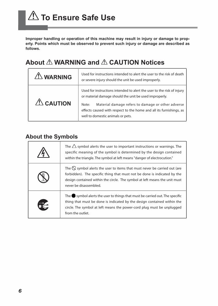
About WARNING and CAUTION Notices
WARNING Used for instructions intended to alert the user to the risk of death
or severe injury should the unit be used improperly.
CAUTION
Used for instructions intended to alert the user to the risk of injury
or material damage should the unit be used improperly.
Note: Material damage refers to damage or other adverse
effects caused with respect to the home and all its furnishings, as
well to domestic animals or pets.
About the SymbolsThe symbol alerts the user to important instructions or warnings. The
specific meaning of the symbol is determined by the design contained
within the triangle. The symbol at left means "danger of electrocution."
The symbol alerts the user to items that must never be carried out (are
forbidden). The specific thing that must not be done is indicated by the
design contained within the circle. The symbol at left means the unit must
never be disassembled.
The symbol alerts the user to things that must be carried out. The specific
thing that must be done is indicated by the design contained within the
circle. The symbol at left means the power-cord plug must be unplugged
from the outlet.

To Ensure Safe Use
7
Incorrect operation may cause injury.
WARNINGBe sure to follow the operation pro-cedures described in this documenta-tion. Never allow anyone unfamiliar with the usage or handling of the machine to touch it.Incorrect usage or handling may lead to an accident.
Keep children away from the ma-chine. The machine includes areas and compo-nents that pose a hazard to children and may result in injury, blindness, choking, or other serious accident.
Never operate the machine while tired or after ingesting alcohol or any medication. Operation requires unimpaired judg-ment. Impaired judgment may result in an accident.
Conduct operations in a clean, bright-ly lit location.Working in a location that is dark or clut-tered may lead to an accident, such as becoming caught in the machine as the result of an inadvertent stumble.
Never use the machine for any pur-pose for which it is not intended, or use the machine in an undue manner that exceeds its capacity. Doing so may result in injury or fire.
Never use a cutting tool that has become dull. Perform frequent main-tenance to keep and use the machine in good working order.Unreasonable usage may result in fire or injury.
WARNINGFor accessories (optional and con-sumable items, power cord, and the like), use only genuine articles com-patible with this machine.Incompatible items may lead to an ac-cident.
Before attempting cleaning, mainte-nance, or attachment or detachment of optional items, disconnect the power cord.Attempting such operations while the machine is connected to a power source may result in injury or electrical shock.
Never attempt to disassemble, repair, or modify the machine.Doing so may result in fire, electrical shock, or injury. Entrust repairs to a trained service technician.
CAUTIONNever climb or lean on the machine.The machine is not made to support a person. Climbing or leaning on the machine may dislodge components and cause a slip or fall, resulting in injury.
Never operate if a front cover is cracked or broken.Doing so may result in injury. If the front cover is cracked, contact your authorized Roland DG Corp. dealer.

To Ensure Safe Use
8
This machine weighs 65 kg (144 lb.)
CAUTIONUnloading and emplacement are op-erations that must be performed by 4 persons or more.Tasks that require undue effort when performed by a small number of persons may result in physical injury. Also, if dropped, such items may cause injury.
Install in a location that is level and stable.Installation in an unsuitable location may cause an accident, including a fall or tipover.
The cutting waste or workpiece may catch fire or pose a health hazard.
WARNINGNever attempt to cut magnesium or any other such flammable material. Fire may occur during cutting.
Keep open flame away from the work area. Cutting waste may ignite. Powdered ma-terial is extremely flammable, and even metal material may catch fire.
When using a vacuum cleaner to take up cutting waste, exercise caution to prevent fire or dust explosion. Taking up fine cuttings using an ordinary vacuum cleaner may cause danger of fire or explosion. Check with the manu-facturer of the vacuum cleaner. When the safety of use cannot be determined, clean using a brush or the like, without using the vacuum cleaner.
CAUTIONWear dust goggles and a mask. Wash away any cutting waste remaining on the hands. Accidentally swallowing or inhaling cutting waste may be hazardous to the health.
To Ensure Safe Use
9
Danger of pinching, entanglement, and burns.
WARNINGNever attempt operation while wearing a necktie, necklace, loose clothing, or gloves. Bind long hair securely.Such items may become caught in the machine, resulting in injury.
Securely fasten the cutting tool and workpiece in place. After securing in place, make sure no wrenches or other articles have inadvertently been left behind.Otherwise such articles may be thrown from the machine with force, posing a risk of injury.
WARNINGExercise caution to avoid being pinched or becoming caught.Inadvertent contact with certain areas may cause the hand or fingers to be pinched or become caught. Use care when performing operations.
Caution: cutting tool.The cutting tool is sharp. To avoid injury, exercise caution.
Caution: high temperatures.The cutting tool and spindle motor be-come hot. Exercise caution to avoid fire or burns.
Danger of electrical short, shock, electrocution, or fire
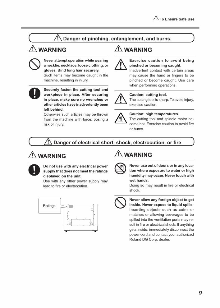
WARNINGDo not use with any electrical power supply that does not meet the ratings displayed on the unit.Use with any other power supply may lead to fire or electrocution.
WARNINGNever use out of doors or in any loca-tion where exposure to water or high humidity may occur. Never touch with wet hands.Doing so may result in fire or electrical shock.
Never allow any foreign object to get inside. Never expose to liquid spills.Inserting objects such as coins or matches or allowing beverages to be spilled into the ventilation ports may re-sult in fire or electrical shock. If anything gets inside, immediately disconnect the power cord and contact your authorized Roland DG Corp. dealer.
To Ensure Safe Use
10
WARNINGNever place any flammable object nearby. Never use a combustible aerosol spray nearby. Never use in any location where gases can ac-cumulate.Combustion or explosion may be a danger.
Handle the power cord, plug, and electrical outlet correctly and with care. Never use any article that is damaged.Using a damaged article may result in fire or electrical shock.
When using an extension cord or power strip, use one that adequately satisfies the machine’s ratings (for voltage, frequency, and current).Use of multiple electrical loads on a single electrical outlet or of a lengthy extension cord may cause fire.
When the machine will be out of use for a prolonged period, disconnect the power cord.This can prevent accidents in the event of current leakage or unintended startup.
Connect to ground.This can prevent fire or electrical shock due to current leakage in the event of malfunction.
Position so that the power plug is within immediate reach at all times.This is to enable quick disconnection of the power plug in the event of an emergency. Install the machine next to an electrical outlet. Also, provide enough empty space to allow immediate access to the electrical outlet.
WARNINGNever use cutting oil.This machine is not designed for the flow of cutting oil. Oil may get inside the machine and cause fire or electrical shock.
Never use a pneumatic blower.This machine is not compatible with a pneumatic blower. Cutting waste may get inside the machine and cause fire or electrical shock.
If sparking, smoke, burning odor, unusual sound, or abnormal opera-tion occurs, immediately unplug the power cord. Never use if any compo-nent is damaged.Continuing to use the machine may result in fire, electrical shock, or injury. Contact your authorized Roland DG Corp. dealer.
Do not use the supplied power supply cord for other products.
To Ensure Safe Use
11
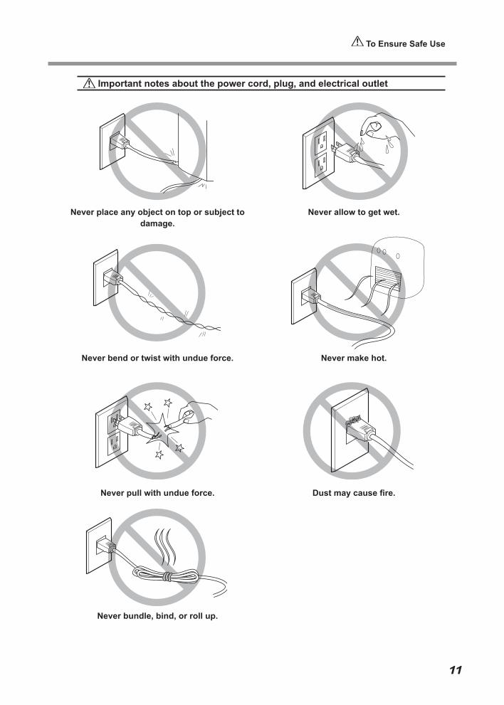
Important notes about the power cord, plug, and electrical outlet
Never place any object on top or subject to damage.
Never bend or twist with undue force.
Never pull with undue force.
Never bundle, bind, or roll up.
Never allow to get wet.
Never make hot.
Dust may cause fire.
To Ensure Safe Use
12
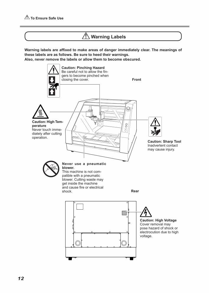
Warning Labels
Warning labels are affixed to make areas of danger immediately clear. The meanings of these labels are as follows. Be sure to heed their warnings. Also, never remove the labels or allow them to become obscured.
Caution: Sharp ToolInadvertent contact may cause injury.
Caution: High Tem-peratureNever touch imme-diately after cutting operation.
Front
Rear
Caution: Pinching HazardBe careful not to allow the fin-gers to become pinched when closing the cover.
Never use a pneumatic blower.This machine is not com-patible with a pneumatic blower. Cutting waste may get inside the machine and cause fire or electrical shock.
Caution: High VoltageCover removal may pose hazard of shock or electrocution due to high voltage.
13
Pour utiliser en toute sécurité
La manipulation ou l'utilisation inadéquates de cet appareil peuvent causer des blessures ou des dommages matériels. Les précautions à prendre pour prévenir les blessures ou les dommages sont décrites ci-dessous.
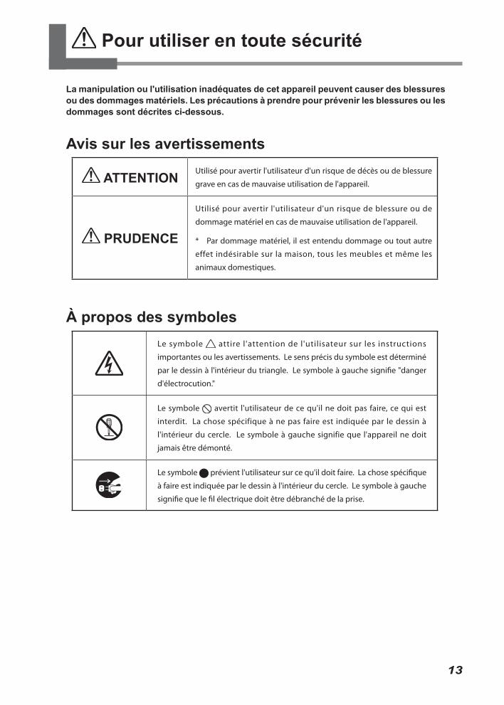
Avis sur les avertissements
ATTENTION Utilisé pour avertir l'utilisateur d'un risque de décès ou de blessure
grave en cas de mauvaise utilisation de l'appareil.
PRUDENCE
Utilisé pour avertir l'utilisateur d'un risque de blessure ou de
dommage matériel en cas de mauvaise utilisation de l'appareil.
* Par dommage matériel, il est entendu dommage ou tout autre
effet indésirable sur la maison, tous les meubles et même les
animaux domestiques.
À propos des symbolesLe symbole attire l'attention de l'utilisateur sur les instructions
importantes ou les avertissements. Le sens précis du symbole est déterminé
par le dessin à l'intérieur du triangle. Le symbole à gauche signifie "danger
d'électrocution."
Le symbole avertit l'utilisateur de ce qu'il ne doit pas faire, ce qui est
interdit. La chose spécifique à ne pas faire est indiquée par le dessin à
l'intérieur du cercle. Le symbole à gauche signifie que l'appareil ne doit
jamais être démonté.
Le symbole prévient l'utilisateur sur ce qu'il doit faire. La chose spécifique
à faire est indiquée par le dessin à l'intérieur du cercle. Le symbole à gauche
signifie que le fil électrique doit être débranché de la prise.
L’utilisation incorrecte peut causer des blessures
ATTENTIONS’assurer de suivre les procédures d’utilisation décrites dans la docu-mentation. Ne jamais permettre à quiconque ne connaît pas le fonc-tionnement ou la manutention de l’appareil de le toucher.L’utilisation ou la manutention incor-rectes peuvent causer un accident.
Garder les enfants loin de l’appareil. L’appareil comporte des zones et des composants qui présentent un danger pour les enfants et qui pourraient causer des blessures, la cécité, la suffocation ou d’autres accidents graves.
Ne jamais faire fonctionner l’appareil après avoir consommé de l’alcool ou des médicaments, ou dans un état de fatigue.L’utilisation de l’appareil exige un jugement sans faille. L’utilisation avec les facultés affaiblies pourrait entraîner un accident.
Utiliser l’appareil dans un endroit propre et bien éclairé.Travailler dans un endroit sombre ou encombré peut causer un accident; l’utilisateur risque, par exemple, de tré-bucher malencontreusement et d’être coincé par une partie de l’appareil.
Ne jamais utiliser l’appareil à des fins autres que celles pour lesquelles il est conçu. Ne jamais l’utiliser de manière abusive ou d’une manière qui dépasse sa capacité.Le non-respect de cette consigne peut causer des blessures ou un incendie.
Ne jamais utiliser un outil de coupe émoussé. Procéder fréquemment aux travaux d’entretien pour garder l’appareil en bon état de fonctionnement.L’usage abusif peut causer un incendie ou des blessures.
PRUDENCENe jamais grimper ni s’appuyer sur la machine.La machine n’est pas conçue pour sup-porter le poids d’une personne. Grimper ou s’appuyer sur la machine peut dé-placer des éléments et causer un faux pas ou une chute, ce qui causerait des blessures.
Ne pas utiliser si un couvercle avant estfissuré ou brisé.Si le couvercle transparent à l'avant ou sur lecôté de l'appareil est fissuré, communiquer avecle revendeur ou le centre de service autorisésde la société Roland DG.
ATTENTIONUtiliser uniquement des acces-soires (d’origine (accessoires en option, articles consommables, câble d’alimentation et autres articles sem-blables), compatibles avec l’appareil.Les articles incompatibles risquent de causer des accidents.
Débrancher le câble d’alimentation avant de procéder au nettoyage ou à l’entretien de l’appareil, et avant d’y fixer ou d’en retirer des accessoires en option.Tenter ces opérations pendant que l’appareil est branché à une source d’alimentation peut causer des blessures ou un choc électrique.
Ne jamais tenter de démonter, de ré-parer ou de modifier l’appareil.Le non-respect de cette consigne ris-que de provoquer un incendie, un choc électrique ou des blessures. Confier les réparations à un technicien ayant la formation requise.
Pour utiliser en toute sécurité
14
Le poids de cet appareil est de 65 kg (144 lb.)
PRUDENCELe déchargement et la mise en place doivent être faits par au moins 4 personnes. Les tâches qui exigent un effort trop grand si elles sont exécutées par un petit nombre de personnes peuvent être cause de blessures. La chute d’articles très lourds peut aussi causer des bles-sures.
PRUDENCEInstaller l’appareil à un endroit stable et plat. Installer l’appareil à un endroit inappro-prié peut provoquer un accident grave comme le renversement ou la chute.
ATTENTIONNe jamais tenter de couper du mag-nésium ni aucun autre matériau inflammable. Un incendie pourrait se produire pendant la coupe.
Ne pas approcher une flamme nue de l’espace de travail. Les rognures de coupe peuvent s’enflammer. Les matériaux pulvérisés sont extrêmement inflammables et même le métal peut s’enflammer.
ATTENTIONSi un aspirateur est utilisé pour ra-masser les rognures de coupe, faire preuve de prudence pour empêcher que la poussière s’enflamme ou explose. Ramasser des rognures fines à l’aide d’un aspirateur ordinaire peut créer un risque d’incendie ou d’explosion. Vérifier auprès du fabricant de l’aspirateur. Dans les cas où il est impossible de déter-miner si un aspirateur peut être utilisé sans danger, se servir d’une brosse ou d’un article semblable plutôt que d’un aspirateur.
PRUDENCEPorter des lunettes de protection et un masque. Rincer toutes les rog-nures de coupe qui pourraient rester collées aux mains. Avaler ou respirer accidentellement des rognures de coupe peut être dangereux pour la santé.
Les débris de coupe peuvent s ’enflammer ou présenter un risque pour la santé.
Pour utiliser en toute sécurité
15
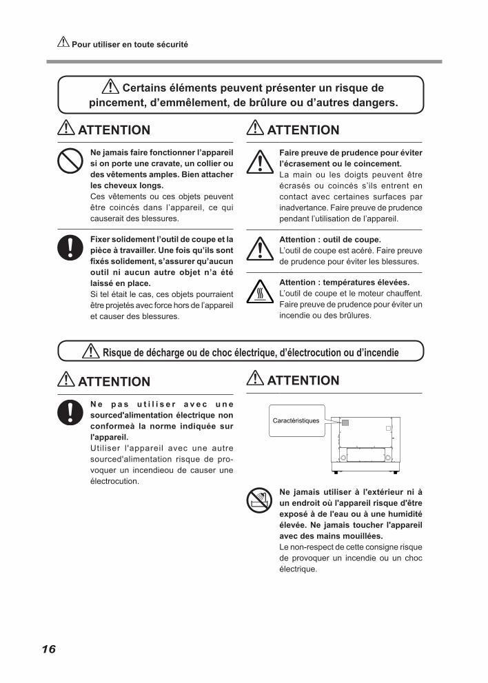
ATTENTIONN e p a s u t i l i s e r a v e c u n e sourced'alimentation électrique non conformeà la norme indiquée sur l'appareil.Utiliser l 'appareil avec une autre sourced'alimentation risque de pro-voquer un incendieou de causer une électrocution.
Risque de décharge ou de choc électrique, d’électrocution ou d’incendie
ATTENTION
Ne jamais utiliser à l'extérieur ni à un endroit où l'appareil risque d'être exposé à de l'eau ou à une humidité élevée. Ne jamais toucher l'appareil avec des mains mouillées.Le non-respect de cette consigne risque de provoquer un incendie ou un choc électrique.
Certains éléments peuvent présenter un risque de pincement, d’emmêlement, de brûlure ou d’autres dangers.
ATTENTIONNe jamais faire fonctionner l’appareil si on porte une cravate, un collier ou des vêtements amples. Bien attacher les cheveux longs. Ces vêtements ou ces objets peuvent être coincés dans l’appareil, ce qui causerait des blessures.
Fixer solidement l’outil de coupe et la pièce à travailler. Une fois qu’ils sont fixés solidement, s’assurer qu’aucun outil ni aucun autre objet n’a été laissé en place. Si tel était le cas, ces objets pourraient être projetés avec force hors de l’appareil et causer des blessures.
ATTENTIONFaire preuve de prudence pour éviter l’écrasement ou le coincement. La main ou les doigts peuvent être écrasés ou coincés s’ils entrent en contact avec certaines surfaces par inadvertance. Faire preuve de prudence pendant l’utilisation de l’appareil.
Attention : outil de coupe. L’outil de coupe est acéré. Faire preuve de prudence pour éviter les blessures.
Attention : températures élevées. L’outil de coupe et le moteur chauffent. Faire preuve de prudence pour éviter un incendie ou des brûlures.
Pour utiliser en toute sécurité
16
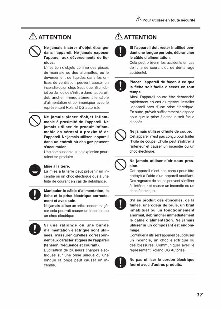
ATTENTIONNe jamais insérer d’objet étranger dans l’appareil. Ne jamais exposer l’appareil aux déversements de liq-uides. L’insertion d’objets comme des pièces de monnaie ou des allumettes, ou le déversement de liquides dans les ori-fices de ventilation peuvent causer un incendie ou un choc électrique. Si un ob-jet ou du liquide s’infiltre dans l’appareil, débrancher immédiatement le câble d’alimentation et communiquer avec le représentant Roland DG autorisé.
Ne jamais placer d’objet inflam-mable à proximité de l’appareil. Ne jamais utiliser de produit inflam-mable en aérosol à proximité de l’appareil. Ne jamais utiliser l’appareil dans un endroit où des gaz peuvent s’accumuler. Une combustion ou une explosion pour-raient se produire.
Mise à la terre. La mise à la terre peut prévenir un in-cendie ou un choc électrique dus à une fuite de courant en cas de défaillance.
Manipuler le câble d’alimentation, la fiche et la prise électrique correcte-ment et avec soin. Ne jamais utiliser un article endommagé, car cela pourrait causer un incendie ou un choc électrique.
Si une rallonge ou une bande d’alimentation électrique sont utili-sées, s’assurer qu’elles correspon-dent aux caractéristiques de l’appareil (tension, fréquence et courant). L’utilisation de plusieurs charges élec-triques sur une prise unique ou une longue rallonge peut causer un in-cendie.
ATTENTIONSi l’appareil doit rester inutilisé pen-dant une longue période, débrancher le câble d’alimentation. Cela peut prévenir les accidents en cas de fuite de courant ou de démarrage accidentel.
Placer l’appareil de façon à ce que la fiche soit facile d’accès en tout temps. Ainsi, l’appareil pourra être débranché rapidement en cas d’urgence. Installer l’appareil près d’une prise électrique. En outre, prévoir suffisamment d’espace pour que la prise électrique soit facile d’accès.
Ne jamais utiliser d’huile de coupe. Cet appareil n’est pas conçu pour traiter l’huile de coupe. L’huile peut s’infiltrer à l’intérieur et causer un incendie ou un choc électrique.
Ne jamais utiliser d’air sous pres-sion. Cet appareil n’est pas conçu pour être nettoyé à l’aide d’un appareil soufflant. Des rognures de coupe peuvent s’infiltrer à l’intérieur et causer un incendie ou un choc électrique.
S’il se produit des étincelles, de la fumée, une odeur de brûlé, un bruit inhabituel ou un fonctionnement anormal, débrancher immédiatement le câble d’alimentation. Ne jamais utiliser si un composant est endom-magé. Continuer à utiliser l’appareil peut causer un incendie, un choc électrique ou des blessures. Communiquer avec le représentant Roland DG Autorisé.
Ne pas utiliser le cordon électrique fourni avec d’autres produits.
Pour utiliser en toute sécurité
17

Remarques importantes à propos du câble d'alimentation, de la fiche et de la prise électrique
Ne jamais déposer aucun objet sur le câble, sur la fiche ou sur la prise car cela risque de
les endommager.
Ne jamais plier ni tordre le câble avec une force excessive.
Ne jamais tirer sur le câble ou la fiche avec une force excessive.
Ne jamais plier ni enrouler le câble.
Ne jamais laisser l'eau toucher le câble, la fiche ou la prise.
Ne jamais chauffer le câble, la fiche ou la prise.
La poussière peut causer un incendie.
Pour utiliser en toute sécurité
18
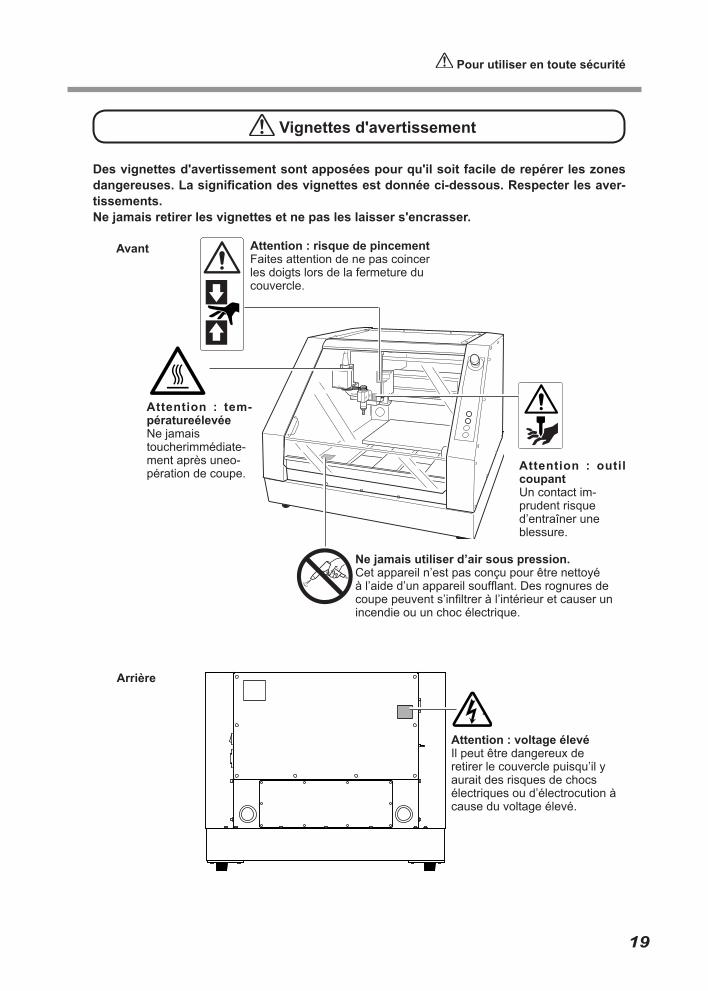
Des vignettes d'avertissement sont apposées pour qu'il soit facile de repérer les zones dangereuses. La signification des vignettes est donnée ci-dessous. Respecter les aver-tissements.Ne jamais retirer les vignettes et ne pas les laisser s'encrasser.
Vignettes d'avertissement
Avant
Attention : outil coupantUn contact im-prudent risque d’entraîner une blessure.
Attention : risque de pincementFaites attention de ne pas coincer les doigts lors de la fermeture du couvercle.
Ne jamais utiliser d’air sous pression.Cet appareil n’est pas conçu pour être nettoyé à l’aide d’un appareil soufflant. Des rognures de coupe peuvent s’infiltrer à l’intérieur et causer un incendie ou un choc électrique.
Attention : voltage élevéIl peut être dangereux de retirer le couvercle puisqu’il y aurait des risques de chocs électriques ou d’électrocution à cause du voltage élevé.
Arrière
Attention : tem-pératureélevéeNe jamais toucherimmédiate-ment après uneo-pération de coupe.
Pour utiliser en toute sécurité
19
20
Important Notes on Handling and Use
This machine is a precision device. To ensure the full performance of this machine, be sure to observe the following important points. Failure to observe these may not only result in loss of performance, but may also cause malfunction or breakdown.
This machine is a precision device.
○ Handle carefully, and never subject the machine to impact or excessive force.○ Diligently keep clean of cutting waste.○ Use within the range of specifications.○ Never attempt to move the spindle unit by hand with undue force.○ Never needlessly touch anywhere inside the machine except for locations specified
in this manual.
Install in a suitable location.
○ Install in a location that meets the specified conditions for temperature, relative humid-ity, and the like.
○ Install in a quiet, stable location offering good operating conditions.○ Never install in out of doors.○ Never use the machine in an environment where silicone substances (oil, grease, spray,
etc.) are present. Doing so may cause poor switch contact.
This machine becomes hot.
○ Never cover the ventilation holes with cloth, tape, or anything else.○ Install in a well-ventilated location.
About Cutters
○ Use a cutter that is suitable for the workpiece and the cutting method.○ The tip of the cutter is breakable. Handle with care, being careful not to drop it.
This machine is suited to cutting resins.
○ Never use it to cut metal.
21
About the Documentation for This Machine
Documentation Included with the Machine
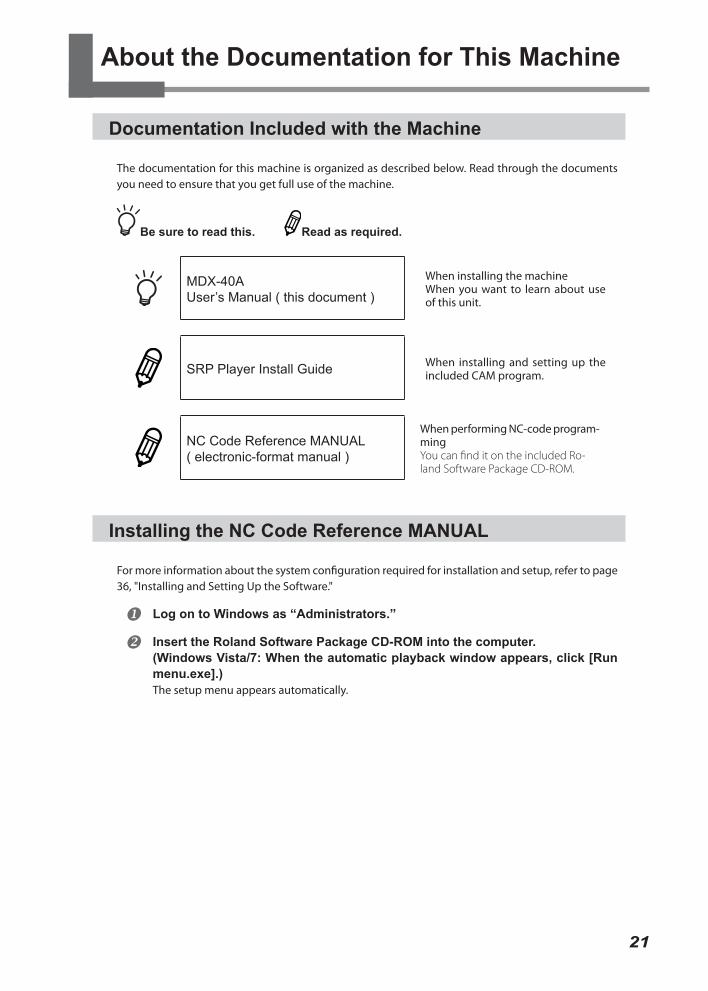
The documentation for this machine is organized as described below. Read through the documents you need to ensure that you get full use of the machine.
Be sure to read this. Read as required.
MDX-40AUser’s Manual ( this document )
When installing the machineWhen you want to learn about use of this unit.
SRP Player Install Guide When installing and setting up the included CAM program.
NC Code Reference MANUAL( electronic-format manual )
When performing NC-code program-mingYou can find it on the included Ro-land Software Package CD-ROM.
Installing the NC Code Reference MANUAL
For more information about the system configuration required for installation and setup, refer to page 36, "Installing and Setting Up the Software."
Log on to Windows as “Administrators.”
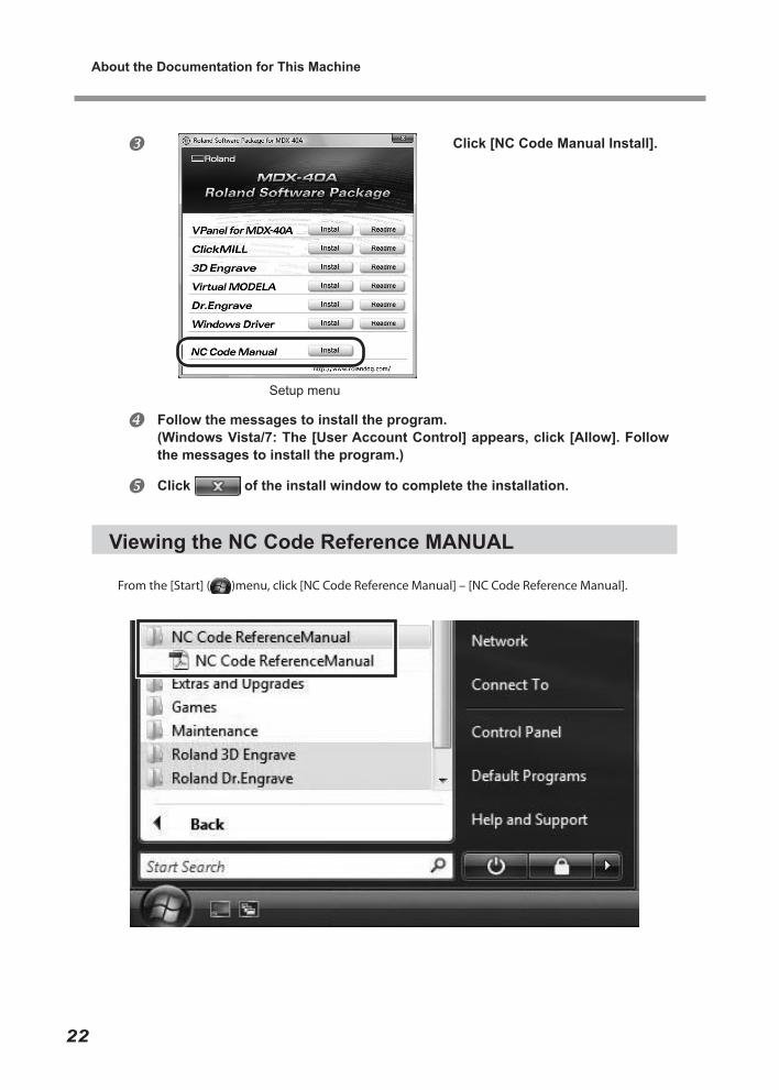
Insert the Roland Software Package CD-ROM into the computer.(Windows Vista/7: When the automatic playback window appears, click [Run menu.exe].)The setup menu appears automatically.
About the Documentation for This Machine
22
Click [NC Code Manual Install].
Follow the messages to install the program.(Windows Vista/7: The [User Account Control] appears, click [Allow]. Follow the messages to install the program.)
Click of the install window to complete the installation.
Viewing the NC Code Reference MANUAL
From the [Start] ( )menu, click [NC Code Reference Manual] – [NC Code Reference Manual].
Setup menu

Chapter 1 Getting Started
This section describes the features of the machine, the part names, and the functions.
1-1 Machine Highlights ..................................................... 24
Overview of the Unit ...................................................... 24
Operating the Machine .................................................. 24
1-2 Part Names and Functions ......................................... 25
Front .............................................................................. 25
Side ............................................................................... 26
VPanel ........................................................................... 27
Built-in Panel ................................................................. 28
23
24 Chapter 1 Getting Started Chapter 1 Getting Started
1-1 Machine Highlights
Overview of the Unit
RML-1/NC code supportThis machine supports both RML-1 and NC code; therefore it is applicable for a wide-range of software. RML-1 is a control command exclusive to Roland D.G. modeling machine. When outputting from the included application to the machine.
Easy-operation VPanelThis machine is operated from the computer screen by using the included application software, “VPanel.” The VPanel moves the tool, turns on/off the spindle rotation, sets the origin, and outputs the cutting data.
A full array of software includedIn order to enable modeling immediately after the cutting data is created, the exclusive CAM softwares are included. Cutting software is also included to meet various usages.
P. 37 “The Software You Can Install and Set Up”
Four-axes machining operation supportInstalling the optional rotary axis unit (A-axis) makes it possible to perform four-axes machining opera-tions such as multiple-surface cutting.
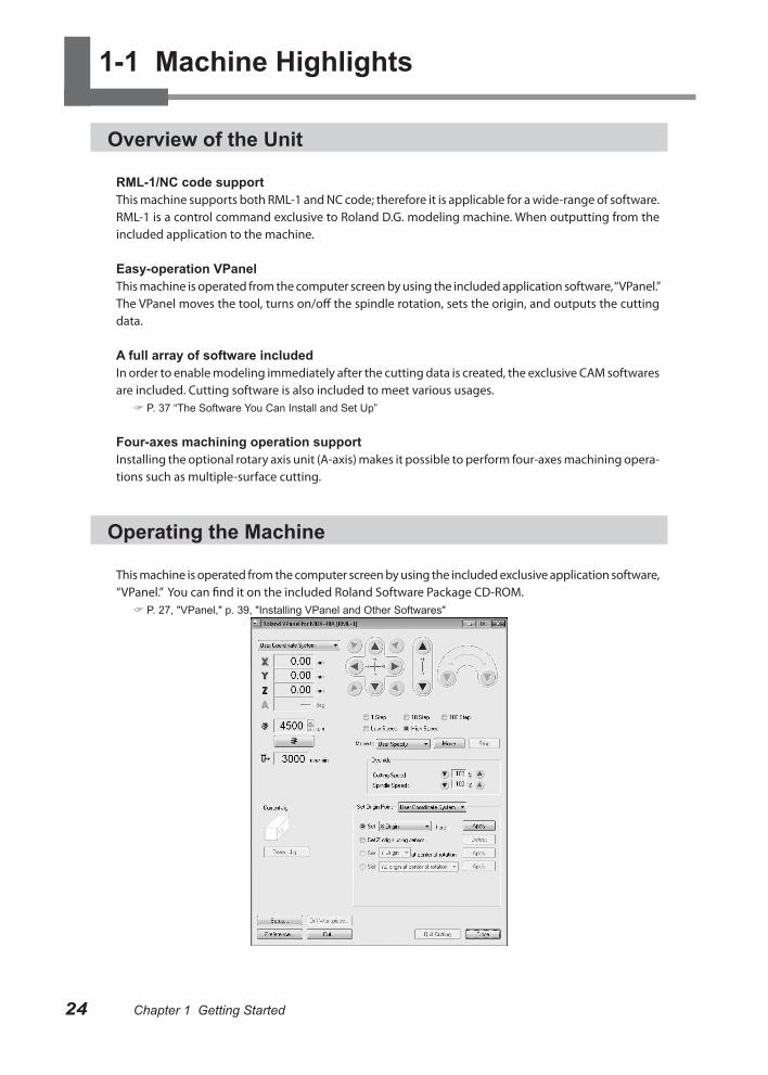
Operating the Machine
This machine is operated from the computer screen by using the included exclusive application software, “VPanel.” You can find it on the included Roland Software Package CD-ROM.
P. 27, "VPanel," p. 39, "Installing VPanel and Other Softwares"
25Chapter 1 Getting Started Chapter 1 Getting Started
1-2 Part Names and Functions
Front
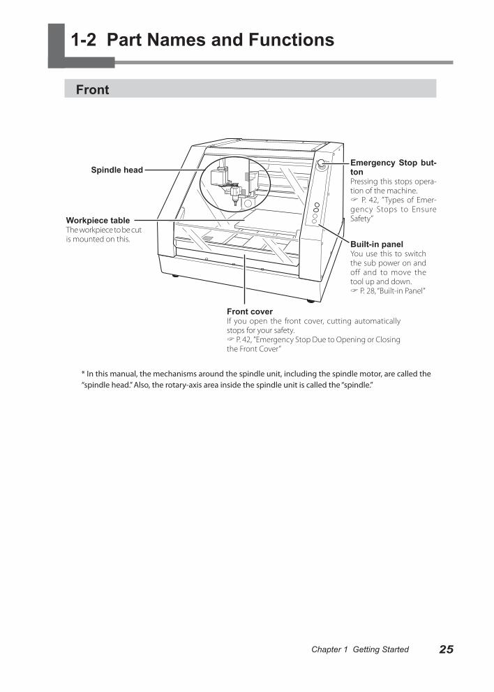
* In this manual, the mechanisms around the spindle unit, including the spindle motor, are called the “spindle head.” Also, the rotary-axis area inside the spindle unit is called the “spindle.”
Built-in panelYou use this to switch the sub power on and off and to move the tool up and down. P. 28, “Built-in Panel”
Emergency Stop but-tonPressing this stops opera-tion of the machine. P. 42, ”Types of Emer-gency Stops to Ensure Safety”Workpiece table
The workpiece to be cut is mounted on this.
Spindle head
Front coverIf you open the front cover, cutting automatically stops for your safety. P. 42, ”Emergency Stop Due to Opening or Closing the Front Cover”
1-2 Part Names and Functions
26 Chapter 1 Getting Started Chapter 1 Getting Started
Side
Right side
Left side
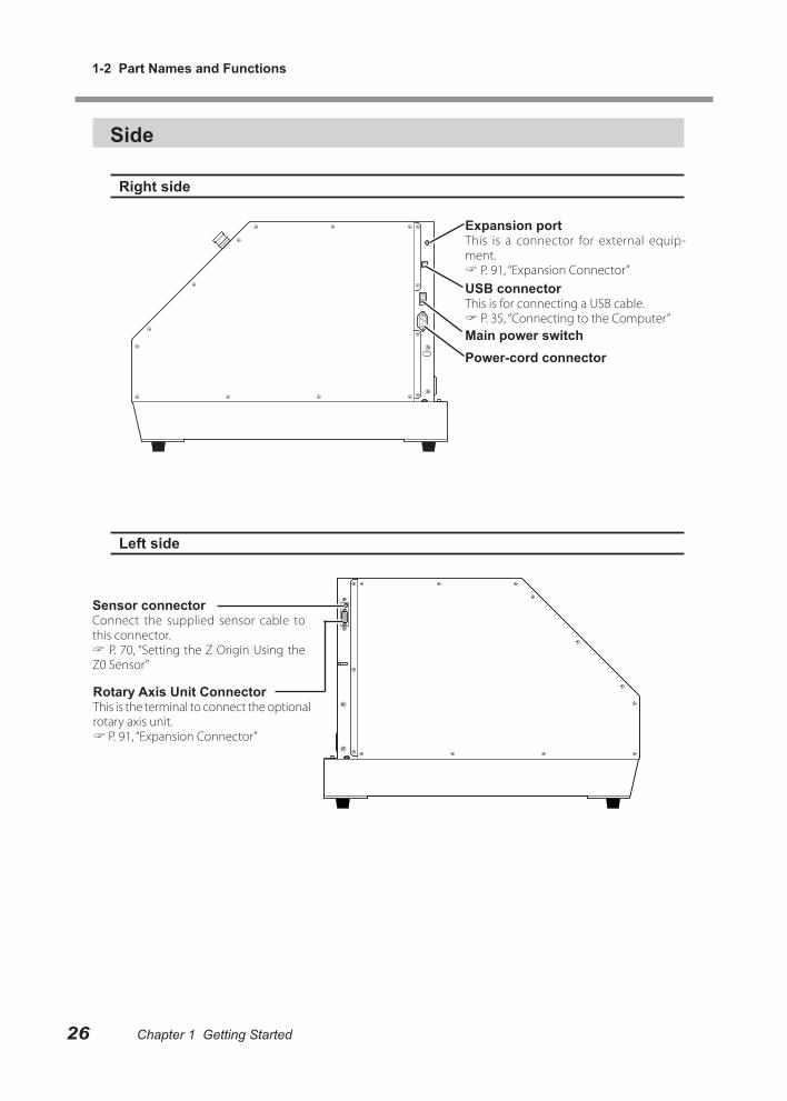
Expansion portThis is a connector for external equip-ment. P. 91, “Expansion Connector”
Rotary Axis Unit ConnectorThis is the terminal to connect the optional rotary axis unit. P. 91, “Expansion Connector”
Sensor connectorConnect the supplied sensor cable to this connector. P. 70, “Setting the Z Origin Using the Z0 Sensor”
USB connectorThis is for connecting a USB cable. P. 35, “Connecting to the Computer”Main power switchPower-cord connector
Chapter 1 Getting Started
1-2 Part Names and Functions
27Chapter 1 Getting Started
VPanel
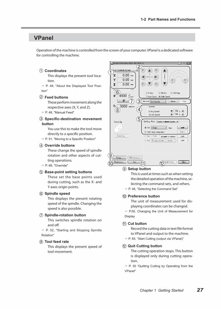
Operation of the machine is controlled from the screen of your computer. VPanel is a dedicated software for controlling the machine.
CoordinatesThis displays the present tool loca-tion.
P. 49, "About the Displayed Tool Posi-tion"
Feed buttonsThese perform movement along the respective axes (X, Y, and Z).
P. 48, "Manual Feed"
Specific-destination movement button
You use this to make the tool move directly to a specific position.
P. 51, "Moving to a Specific Position"
Override buttonsThese change the speed of spindle rotation and other aspects of cut-ting operations.
P. 68, "Override"
Base-point setting buttonsThese set the base points used during cutting, such as the X- and Y-axes origin points.
Spindle speedThis displays the present rotating speed of the spindle. Changing the speed is also possible.
Spindle-rotation buttonThis switches spindle rotation on and off.
P. 52, "Starting and Stopping Spindle Rotation"
Tool feed rateThis displays the present speed of tool movement.
Setup buttonThis is used at times such as when setting the detailed operation of the machine, se-lecting the command sets, and others.
P. 46, “Selecting the Command Set”
Preference buttonThe unit of measurement used for dis-playing coordinates can be changed.
P.50, Changing the Unit of Measurement for Display
Cut buttonRecord the cutting data in text file format to VPanel and output to the machine.
P. 65, “Start Cutting (output via VPanel)”
Quit Cutting buttonThe cutting operation stops. This button is displayed only during cutting opera-tion.
P. 55 “Quitting Cutting by Operating from the VPanel"
1-2 Part Names and Functions
28 Chapter 1 Getting Started
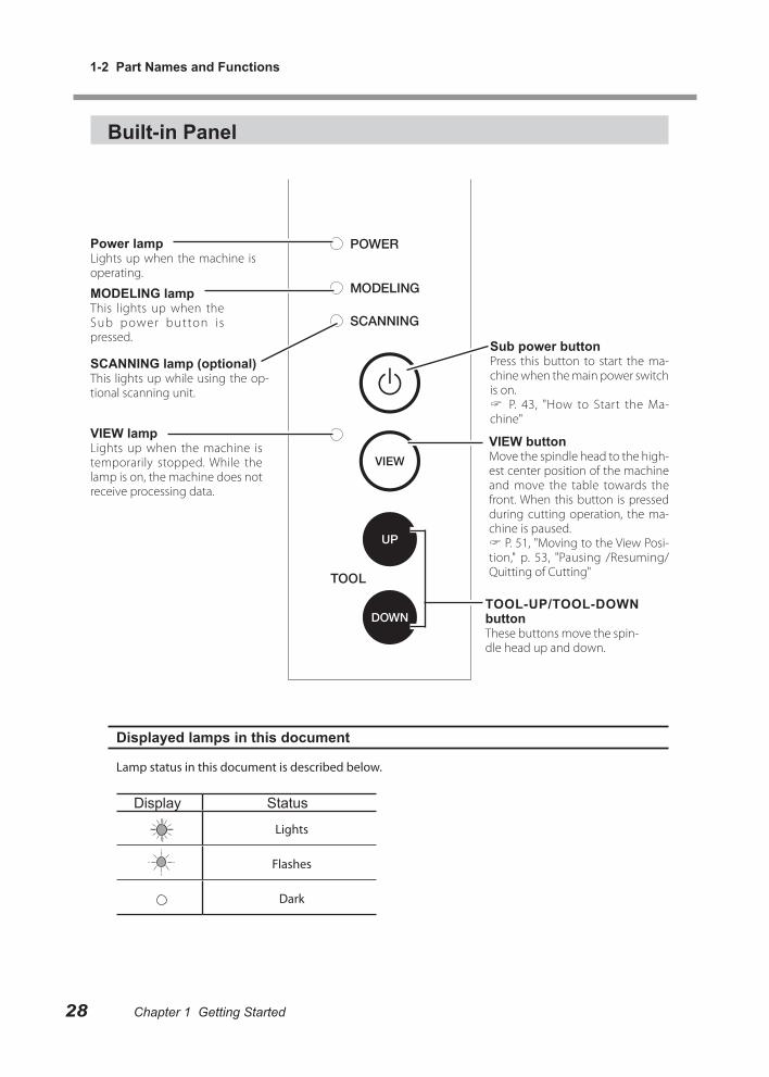
VIEW buttonMove the spindle head to the high-est center position of the machine and move the table towards the front. When this button is pressed during cutting operation, the ma-chine is paused. P. 51, "Moving to the View Posi-tion," p. 53, "Pausing /Resuming/Quitting of Cutting"
Sub power buttonPress this button to start the ma-chine when the main power switch is on. P. 43, "How to Start the Ma-chine"
MODELING lampThis lights up when the Sub power button is pressed.
SCANNING lamp (optional)This lights up while using the op-tional scanning unit.
Built-in Panel
Displayed lamps in this document
Lamp status in this document is described below.
Display Status
Lights
Flashes
Dark
Power lampLights up when the machine is operating.
VIEW lampLights up when the machine is temporarily stopped. While the lamp is on, the machine does not receive processing data.
TOOL-UP/TOOL-DOWN buttonThese buttons move the spin-dle head up and down.

Chapter 2 Installation and Setup
This describes what you need to do before you use the machine, including checking and verifying the included items, how to install the machine, and how to install and set up the included softwares.
2-1 Checking the Included Items ...................................... 30
2-2 Installation ................................................................... 31
Installation Environment ................................................ 31
Installation Environment ................................................ 31
Removing and Storing the Retainers............................. 33
2-3 Cable Connections ..................................................... 34
Connecting the Power Cord .......................................... 34
Connecting to the Computer.......................................... 35
2-4 Installing and Setting Up the Software........................ 36
System Requirements ................................................... 36
The Software You Can Install and Set Up ..................... 37
Installing the Windows-based Driver ............................. 38
Installing VPanel and Other Softwares .......................... 39
Viewing the Documentation for the Softwares ............... 40
29
30 Chapter 2 Installation and Setup Chapter 2 Installation and Setup
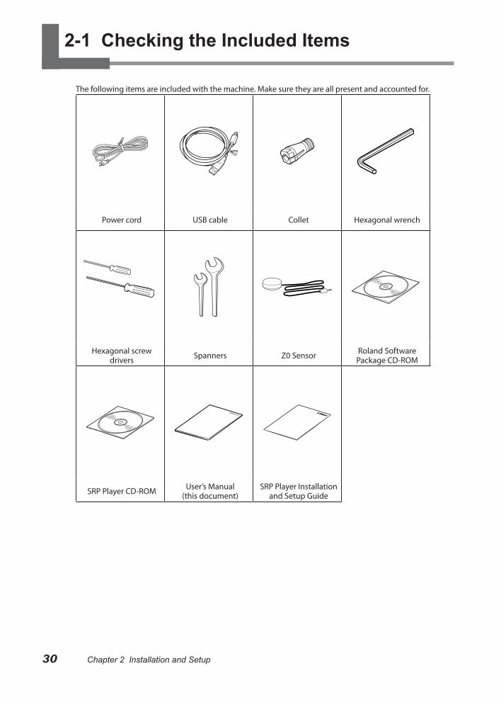
2-1 Checking the Included Items
The following items are included with the machine. Make sure they are all present and accounted for.
Power cord USB cable Collet Hexagonal wrench
Hexagonal screw drivers Spanners Z0 Sensor Roland Software
Package CD-ROM
SRP Player CD-ROM User’s Manual (this document)
SRP Player Installation and Setup Guide

31Chapter 2 Installation and Setup Chapter 2 Installation and Setup
2-2 Installation
Installation Environment
WARNING Unloading and emplacement are operations that must be performed by 4 persons or more.Tasks that require undue effort when performed by a small number of persons may result in physical injury. Also, if dropped, such items may cause injury.
The weight of the machine alone is 65 kg (144 lb.). Perform unloading and emplacement with care.
Installation Environment
Install in a quiet, stable location offering good operating conditions. An unsuitable location can cause accident, fire, faulty operation, or breakdown.
WARNING Install in a location that is level and stable.Installation in an unsuitable location may cause an accident, including a fall or tipover.
WARNING Never install in a location exposed to open flame.Cutting waste may ignite. Powdered material is extremely flammable, and even metal material may catch fire.
WARNING Never install close to any flammable object or in a gas-filled loca-tion.Combustion or explosion may be a danger.
WARNING Never install out of doors or in any location where exposure to water or high humidity may occur.Doing so may result in fire or electrical shock.
WARNING Position so that the power plug is within immediate reach at all times.This is to enable quick disconnection of the power plug in the event of an emergency. Install the machine next to an electrical outlet. Also, provide enough empty space to allow immediate access to the electri-cal outlet.
○ Never install in a location subject to wide fluctuations in temperature or humidity.○ Never install in a location subject to shaking or vibration.○ Never install in a location where the floor is tilted, not level, or unstable.○ Never install in a dusty or dirty location, or out of doors.○ Never install in a location exposed to direct sunlight or near air-conditioning or heating equip-
ment.○ Never install in a location exposed to considerable electrical or magnetic noise, or other forms of
electromagnetic energy.○ Never install in an environment where silicone substances (oil, grease, spray, etc.) are present.
2-2 Installation
32 Chapter 2 Installation and Setup Chapter 2 Installation and Setup
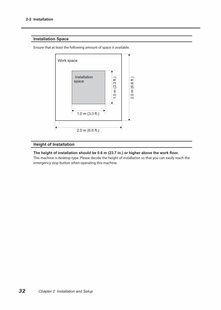
Installation Space
Ensure that at least the following amount of space is available.
Height of Installation
The height of installation should be 0.6 m (23.7 in.) or higher above the work floor.This machine is desktop type. Please decide the height of installation so that you can easily reach the emergency stop button when operating this machine.
Installation space
Work space
1.0 m (3.3 ft.)1.
0 m
(3.3
ft.)
2.0
m (6
.6 ft
.)2.0 m (6.6 ft.)
Chapter 2 Installation and Setup
2-2 Installation
33Chapter 2 Installation and Setup
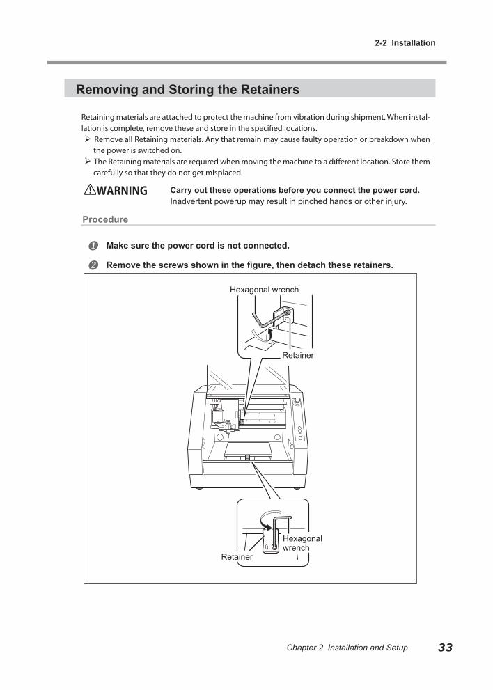
Removing and Storing the Retainers
Retaining materials are attached to protect the machine from vibration during shipment. When instal-lation is complete, remove these and store in the specified locations. Remove all Retaining materials. Any that remain may cause faulty operation or breakdown when
the power is switched on. The Retaining materials are required when moving the machine to a different location. Store them
carefully so that they do not get misplaced.
WARNING Carry out these operations before you connect the power cord.Inadvertent powerup may result in pinched hands or other injury.
Procedure
Make sure the power cord is not connected.
Remove the screws shown in the figure, then detach these retainers.
Retainer
Retainer
Hexagonal wrench
Hexagonal wrench
Chapter 2 Installation and Setup34 Chapter 2 Installation and Setup Chapter 2 Installation and Setup
2-3 Cable Connections
Connecting the Power Cord
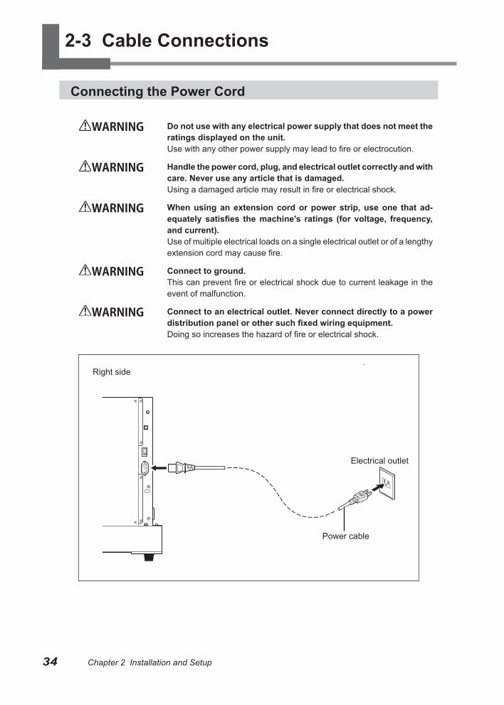
WARNING Do not use with any electrical power supply that does not meet the ratings displayed on the unit.Use with any other power supply may lead to fire or electrocution.
WARNING Handle the power cord, plug, and electrical outlet correctly and with care. Never use any article that is damaged.Using a damaged article may result in fire or electrical shock.
WARNING When using an extension cord or power strip, use one that ad-equately satisfies the machine's ratings (for voltage, frequency, and current).Use of multiple electrical loads on a single electrical outlet or of a lengthy extension cord may cause fire.
WARNING Connect to ground.This can prevent fire or electrical shock due to current leakage in the event of malfunction.
WARNING Connect to an electrical outlet. Never connect directly to a power distribution panel or other such fixed wiring equipment.Doing so increases the hazard of fire or electrical shock.
Right side
Electrical outlet
Power cable
2-3 Cable Connections
35Chapter 2 Installation and SetupChapter 2 Installation and Setup Chapter 2 Installation and Setup
Connecting to the Computer
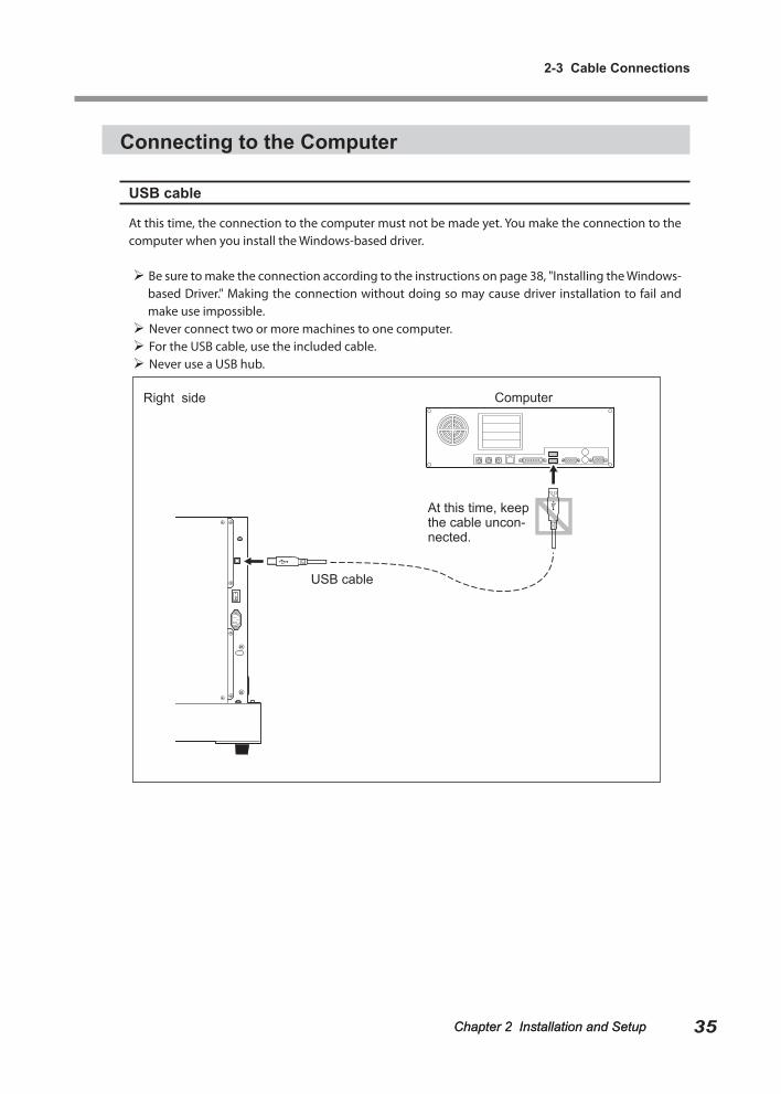
USB cable
At this time, the connection to the computer must not be made yet. You make the connection to the computer when you install the Windows-based driver.
Be sure to make the connection according to the instructions on page 38, "Installing the Windows-based Driver." Making the connection without doing so may cause driver installation to fail and make use impossible.
Never connect two or more machines to one computer. For the USB cable, use the included cable. Never use a USB hub.
USB cable
Right side Computer
At this time, keep the cable uncon-nected.
Chapter 2 Installation and Setup36 Chapter 2 Installation and Setup Chapter 2 Installation and Setup
2-4 Installing and Setting Up the Software
System Requirements
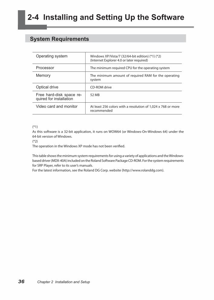
Operating system Windows XP/Vista/7 (32/64-bit edition) (*1) (*2)(Internet Explorer 4.0 or later required)
Processor The minimum required CPU for the operating system
Memory The minimum amount of required RAM for the operating system
Optical drive CD-ROM drive
Free hard-disk space re-quired for installation
52 MB
Video card and monitor At least 256 colors with a resolution of 1,024 x 768 or more recommended
(*1)As this software is a 32-bit application, it runs on WOW64 (or Windows-On-Windows 64) under the 64-bit version of Windows.(*2)The operation in the Windows XP mode has not been verified.
This table shows the minimum system requirements for using a variety of applications and the Windows-based driver (MDX-40A) included on the Roland Software Package CD-ROM. For the system requirements for SRP Player, refer to its user’s manuals.For the latest information, see the Roland DG Corp. website (http://www.rolanddg.com).
2-4 Installing and Setting Up the Software
37Chapter 2 Installation and SetupChapter 2 Installation and Setup Chapter 2 Installation and Setup
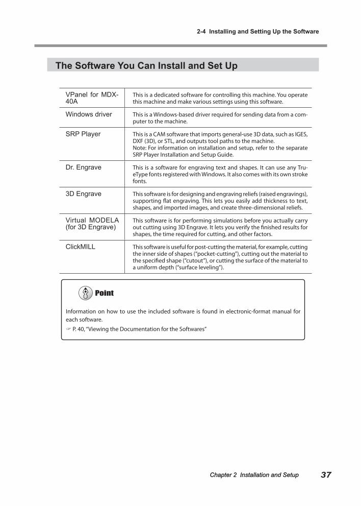
The Software You Can Install and Set Up
VPanel for MDX-40A
This is a dedicated software for controlling this machine. You operate this machine and make various settings using this software.
Windows driver This is a Windows-based driver required for sending data from a com-puter to the machine.
SRP Player This is a CAM software that imports general-use 3D data, such as IGES, DXF (3D), or STL, and outputs tool paths to the machine.Note: For information on installation and setup, refer to the separate SRP Player Installation and Setup Guide.
Dr. Engrave This is a software for engraving text and shapes. It can use any Tru-eType fonts registered with Windows. It also comes with its own stroke fonts.
3D Engrave This software is for designing and engraving reliefs (raised engravings), supporting flat engraving. This lets you easily add thickness to text, shapes, and imported images, and create three-dimensional reliefs.
Virtual MODELA (for 3D Engrave)
This software is for performing simulations before you actually carry out cutting using 3D Engrave. It lets you verify the finished results for shapes, the time required for cutting, and other factors.
ClickMILL This software is useful for post-cutting the material, for example, cutting the inner side of shapes (“pocket-cutting”), cutting out the material to the specified shape (“cutout”), or cutting the surface of the material to a uniform depth (“surface leveling”).
Information on how to use the included software is found in electronic-format manual for each software.
P. 40, “Viewing the Documentation for the Softwares”
2-4 Installing and Setting Up the Software
38 Chapter 2 Installation and Setup Chapter 2 Installation and Setup
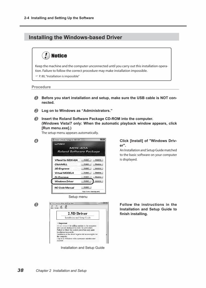
Installing the Windows-based Driver
Procedure
Before you start installation and setup, make sure the USB cable is NOT con-nected.
Log on to Windows as “Administrators.”
Insert the Roland Software Package CD-ROM into the computer.(Windows Vista/7 only: When the automatic playback window appears, click [Run menu.exe].)The setup menu appears automatically.
Click [Install] of "Windows Driv-er".An Installation and Setup Guide matched to the basic software on your computer is displayed.
Follow the instructions in the Installation and Setup Guide to finish installing.
Keep the machine and the computer unconnected until you carry out this installation opera-tion. Failure to follow the correct procedure may make installation impossible.
P. 80, “Installation is impossible”
Setup menu
Installation and Setup Guide
Chapter 2 Installation and Setup
2-4 Installing and Setting Up the Software
39Chapter 2 Installation and Setup
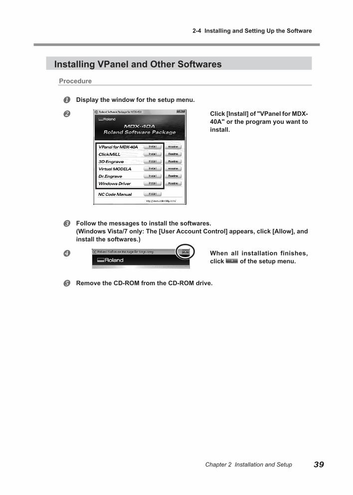
Installing VPanel and Other SoftwaresProcedure
Display the window for the setup menu.
Click [Install] of "VPanel for MDX-40A" or the program you want to install.
Follow the messages to install the softwares.(Windows Vista/7 only: The [User Account Control] appears, click [Allow], and install the softwares.)
When all installation finishes, click of the setup menu.
Remove the CD-ROM from the CD-ROM drive.
2-4 Installing and Setting Up the Software
40 Chapter 2 Installation and Setup Chapter 2 Installation and Setup
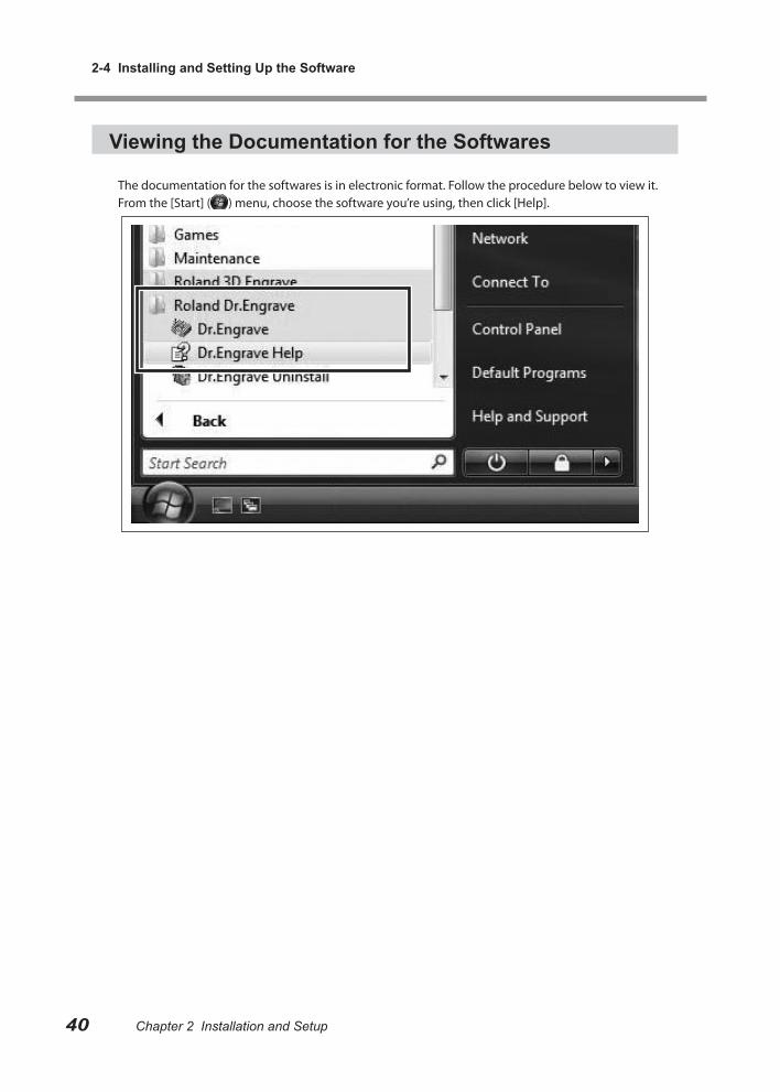
Viewing the Documentation for the Softwares
The documentation for the softwares is in electronic format. Follow the procedure below to view it.From the [Start] ( ) menu, choose the software you’re using, then click [Help].

Chapter 3 Basic Operation
This describes the basic operation methods. If you're using the ma-chine for the first time, then before you start operations, be sure to read this.
3-1 Types of Emergency Stops to Ensure Safety ............. 42
How to Perform an Emergency Stop. ............................ 42
To Cancel an Emergency Stop ...................................... 42
Emergency Stop Due to Opening or Closing the Front Cover ............................................................................. 42
3-2 Starting and Quitting ................................................... 43
How to Start the Machine .............................................. 43
Shutdown ....................................................................... 45
3-3 Selecting the Command Set ....................................... 46
What is Command Set? ................................................. 46
Selecting Command Set ................................................ 46
3-4 Moving the Tool ........................................................... 48
Manual Feed .................................................................. 48
About the Displayed Tool Position ................................. 49
Moving to a Specific Position ......................................... 51
Moving to the VIEW Position ......................................... 51
3-5 Starting and Stopping Spindle Rotation ...................... 52
Starting or Stopping the Spindle .................................... 52
3-6 Pausing/Resuming/Quitting of Cutting ........................ 53
Pausing and Resuming of Cutting by Operation of the Machine ......................................................................... 53
Quitting Cutting by Operation of the Machine................ 54
Quitting Cutting by Operating from the VPanel ............. 55
41

42 Chapter 3 Basic Operation Chapter 3 Basic Operation
3-1 Types of Emergency Stops to Ensure Safety
How to Perform an Emergency Stop.
Press the Emergency Stop but-ton.Operation stops immediately.
To Cancel an Emergency Stop
Turn the button in the direction of the arrows.
Emergency Stop Due to Opening or Closing the Front Cover
To ensure safety, opening a front cover during cutting or spindle rotation causes an emergency stop to occur. At the operation panel, the MODELING lamp and the VIEW lamp flash. Operation cannot be resumed by closing the front cover. In order to resume the operation, restart the machine following the instruction displayed on the VPanel. P. 43, “Starting and Quitting”
43Chapter 3 Basic Operation Chapter 3 Basic Operation
3-2 Starting and Quitting
How to Start the Machine
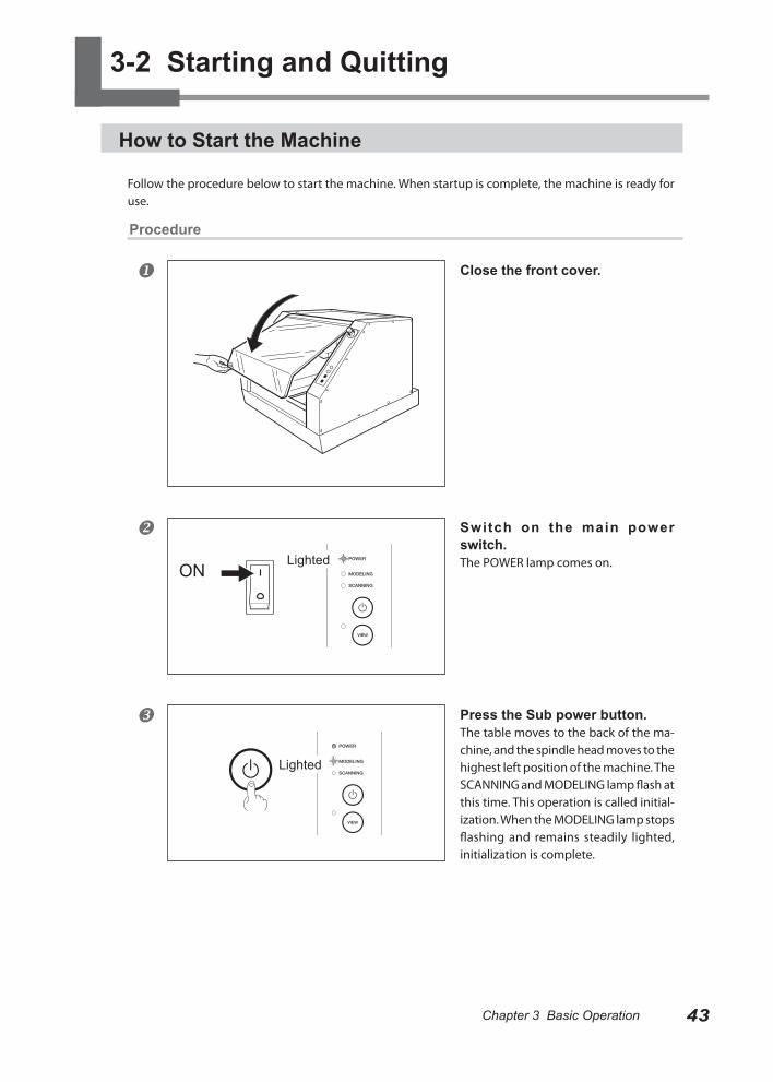
Follow the procedure below to start the machine. When startup is complete, the machine is ready for use.
Procedure
Close the front cover.
Switch on the main power switch.The POWER lamp comes on.
Press the Sub power button.The table moves to the back of the ma-chine, and the spindle head moves to the highest left position of the machine. The SCANNING and MODELING lamp flash at this time. This operation is called initial-ization. When the MODELING lamp stops flashing and remains steadily lighted, initialization is complete.
LightedON
Lighted
3-2 Starting and Quitting
44 Chapter 3 Basic Operation Chapter 3 Basic Operation
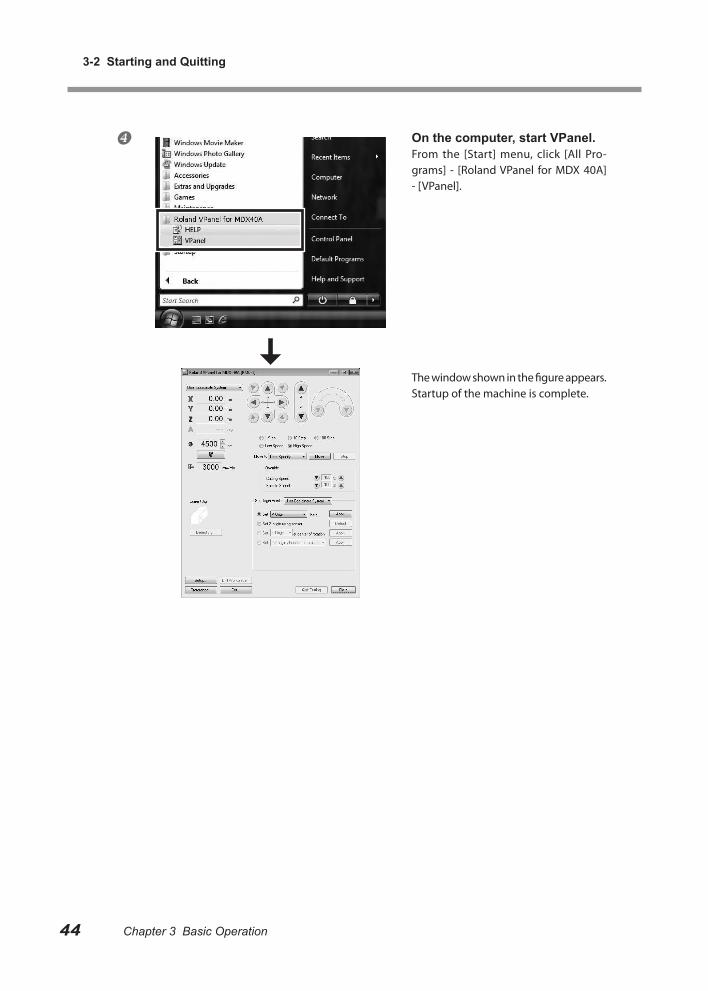
On the computer, start VPanel.From the [Start] menu, click [All Pro-grams] - [Roland VPanel for MDX 40A] - [VPanel].
The window shown in the figure appears. Startup of the machine is complete.
Chapter 3 Basic Operation
3-2 Starting and Quitting
45Chapter 3 Basic Operation
ShutdownProcedure
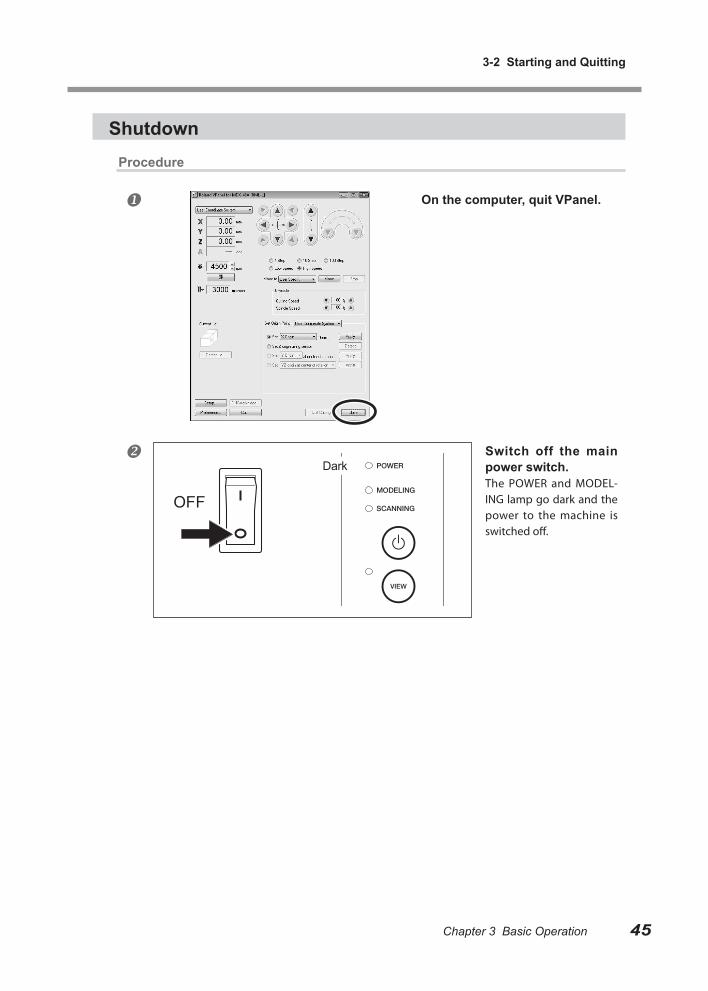
On the computer, quit VPanel.
Switch off the main power switch.The POWER and MODEL-ING lamp go dark and the power to the machine is switched off.
Dark
OFF
Chapter 3 Basic Operation46 Chapter 3 Basic Operation Chapter 3 Basic Operation
3-3 Selecting the Command Set
What is Command Set?
In this machine, the following command sets are available for selection.
RML-1Select when you want to use the software that is included with the machine.
NC codeSelect when you want to use the NC code. For the details of NC code, refer to "NC Code Specifica-tion" on page 87 and "NC Code Reference Guide" that is included with the machine.
Selected automatically (RML-1/NC Code)The machine becomes ready to accept the cutting programs of RML-1 and NC code command sets.
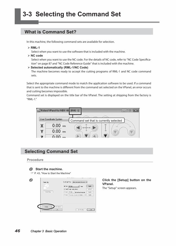
Select the appropriate command mode to match the application software to be used. If a command that is sent to the machine is different from the command set selected on the VPanel, an error occurs and cutting becomes impossible.Command set is displayed on the title bar of the VPanel. The setting at shipping from the factory is “RML-1.”
Selecting Command SetProcedure
Start the machine. P. 43, "How to Start the Machine"
Click the [Setup] button on the VPanel.The "Setup" screen appears.
Command set that is currently selected
Chapter 3 Basic Operation
3-3 Selecting the Command Set
47Chapter 3 Basic Operation Chapter 3 Basic Operation
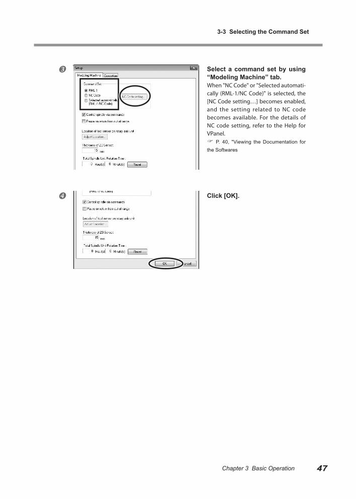
Select a command set by using “Modeling Machine” tab.When "NC Code" or "Selected automati-cally (RML-1/NC Code)" is selected, the [NC Code setting…] becomes enabled, and the setting related to NC code becomes available. For the details of NC code setting, refer to the Help for VPanel. P. 40, "Viewing the Documentation for the Softwares
Click [OK].
Chapter 3 Basic Operation Chapter 3 Basic Operation48 Chapter 3 Basic Operation Chapter 3 Basic Operation
3-4 Moving the Tool
Manual Feed
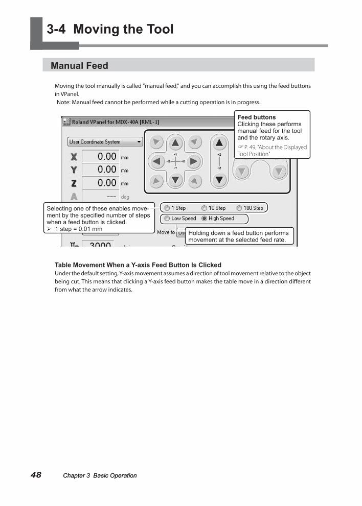
Moving the tool manually is called "manual feed," and you can accomplish this using the feed buttons in VPanel.Note: Manual feed cannot be performed while a cutting operation is in progress.
Table Movement When a Y-axis Feed Button Is ClickedUnder the default setting, Y-axis movement assumes a direction of tool movement relative to the object being cut. This means that clicking a Y-axis feed button makes the table move in a direction different from what the arrow indicates.
Selecting one of these enables move-ment by the specified number of steps when a feed button is clicked. 1 step = 0.01 mm
Holding down a feed button performs movement at the selected feed rate.
Feed buttonsClicking these performs manual feed for the tool and the rotary axis. P. 49, "About the Displayed Tool Position"
Chapter 3 Basic Operation
3-4 Moving the Tool
49Chapter 3 Basic OperationChapter 3 Basic Operation Chapter 3 Basic Operation
About the Displayed Tool Position
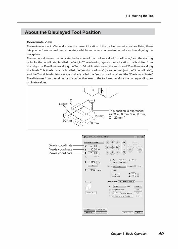
Coordinate ViewThe main window in VPanel displays the present location of the tool as numerical values. Using these lets you perform manual feed accurately, which can be very convenient in tasks such as aligning the workpiece.The numerical values that indicate the location of the tool are called "coordinates," and the starting point for the coordinates is called the "origin." The following figure shows a location that is shifted from the origin by 50 millimeters along the X-axis, 30 millimeters along the Y-axis, and 20 millimeters along the Z-axis. This X-axis distance is called the "X-axis coordinate" (or sometimes just the "X coordinate"), and the Y- and Z-axis distances are similarly called the "Y-axis coordinate" and the "Z-axis coordinate." The distances from the origin for the respective axes to the tool are therefore the corresponding co-ordinate values.
This position is expressed as "X = 50 mm, Y = 30 mm, Z = 20 mm."
X-axis coordinate
Origin
50 mm20 mm
30 mm
Y-axis coordinateZ-axis coordinate
3-4 Moving the Tool
50 Chapter 3 Basic Operation Chapter 3 Basic Operation
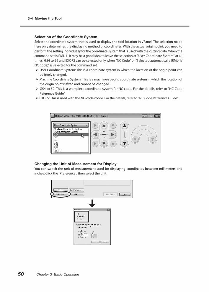
Selection of the Coordinate SystemSelect the coordinate system that is used to display the tool location in VPanel. The selection made here only determines the displaying method of coordinates. With the actual origin point, you need to perform the setting individually for the coordinate system that is used with the cutting data. When the command set is RML-1, it may be a good idea to leave the selection at "User Coordinate System" at all times. G54 to 59 and EXOFS can be selected only when "NC Code" or "Selected automatically (RML-1/NC Code)" is selected for the command set. User Coordinate System: This is a coordinate system in which the location of the origin point can
be freely changed. Machine Coordinate System: This is a machine-specific coordinate system in which the location of
the origin point is fixed and cannot be changed. G54 to 59: This is a workpiece coordinate system for NC code. For the details, refer to "NC Code
Reference Guide". EXOFS: This is used with the NC-code mode. For the details, refer to "NC Code Reference Guide."
Changing the Unit of Measurement for DisplayYou can switch the unit of measurement used for displaying coordinates between millimeters and inches. Click the [Preference], then select the unit.
Chapter 3 Basic Operation
3-4 Moving the Tool
51Chapter 3 Basic Operation
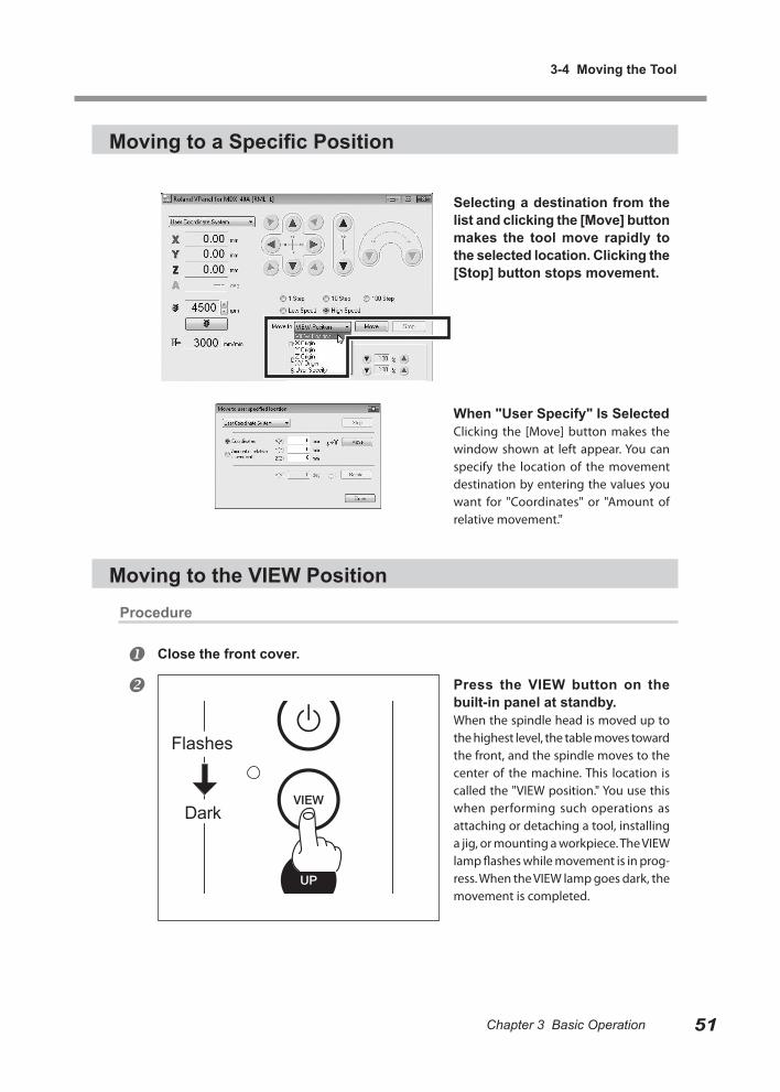
Moving to a Specific Position
Selecting a destination from the list and clicking the [Move] button makes the tool move rapidly to the selected location. Clicking the [Stop] button stops movement.
When "User Specify" Is SelectedClicking the [Move] button makes the window shown at left appear. You can specify the location of the movement destination by entering the values you want for "Coordinates" or "Amount of relative movement."
Moving to the VIEW PositionProcedure
Close the front cover.
Press the VIEW button on the built-in panel at standby.When the spindle head is moved up to the highest level, the table moves toward the front, and the spindle moves to the center of the machine. This location is called the "VIEW position." You use this when performing such operations as attaching or detaching a tool, installing a jig, or mounting a workpiece. The VIEW lamp flashes while movement is in prog-ress. When the VIEW lamp goes dark, the movement is completed.
Flashes
Dark
52 Chapter 3 Basic Operation Chapter 3 Basic Operation
3-5 Starting and Stopping Spindle Rotation
Starting or Stopping the Spindle
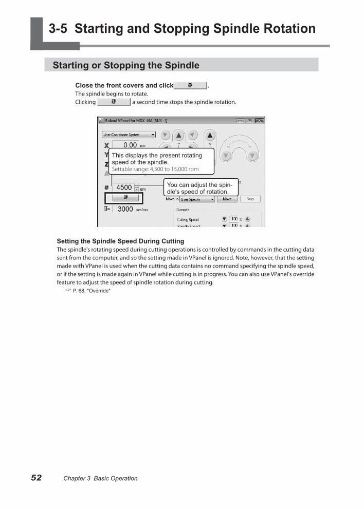
Close the front covers and click .The spindle begins to rotate.Clicking a second time stops the spindle rotation.
Setting the Spindle Speed During CuttingThe spindle's rotating speed during cutting operations is controlled by commands in the cutting data sent from the computer, and so the setting made in VPanel is ignored. Note, however, that the setting made with VPanel is used when the cutting data contains no command specifying the spindle speed, or if the setting is made again in VPanel while cutting is in progress. You can also use VPanel's override feature to adjust the speed of spindle rotation during cutting. P. 68, "Override"
You can adjust the spin-dle's speed of rotation.
This displays the present rotating speed of the spindle.Settable range: 4,500 to 15,000 rpm
53Chapter 3 Basic Operation Chapter 3 Basic Operation
3-6 Pausing/Resuming/Quitting of Cutting
Pausing and Resuming of Cutting by Operation of the Machine
This operation pauses cutting. You perform it using the built-in panel. This also makes it possible to resume cutting at the paused position after an operation such as moving the tool to check the status of the workpiece.
Procedure
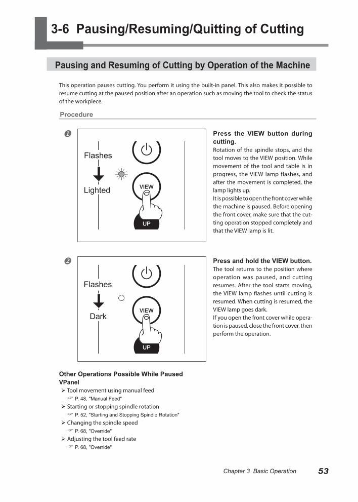
Press the VIEW button during cutting.Rotation of the spindle stops, and the tool moves to the VIEW position. While movement of the tool and table is in progress, the VIEW lamp flashes, and after the movement is completed, the lamp lights up.It is possible to open the front cover while the machine is paused. Before opening the front cover, make sure that the cut-ting operation stopped completely and that the VIEW lamp is lit.
Press and hold the VIEW button.The tool returns to the position where operation was paused, and cutting resumes. After the tool starts moving, the VIEW lamp flashes until cutting is resumed. When cutting is resumed, the VIEW lamp goes dark.If you open the front cover while opera-tion is paused, close the front cover, then perform the operation.
Other Operations Possible While PausedVPanel Tool movement using manual feed P. 48, "Manual Feed"
Starting or stopping spindle rotation P. 52, "Starting and Stopping Spindle Rotation"
Changing the spindle speed P. 68, "Override"
Adjusting the tool feed rate P. 68, "Override"
Flashes
Lighted
Flashes
Dark
3-6 Pausing/Resuming/Quitting of Cutting
54 Chapter 3 Basic Operation Chapter 3 Basic Operation
Quitting Cutting by Operation of the Machine
This stops cutting through operation using the built-in panel. Unlike pausing operation, cutting can-not be resumed.
Procedure
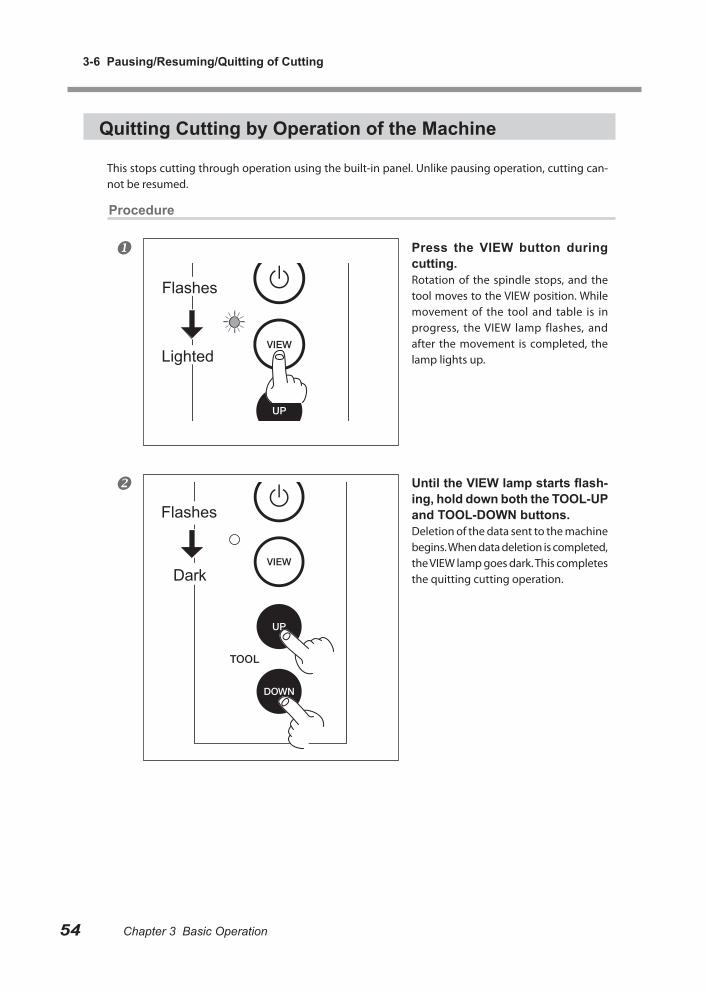
Press the VIEW button during cutting.Rotation of the spindle stops, and the tool moves to the VIEW position. While movement of the tool and table is in progress, the VIEW lamp flashes, and after the movement is completed, the lamp lights up.
Until the VIEW lamp starts flash-ing, hold down both the TOOL-UP and TOOL-DOWN buttons.Deletion of the data sent to the machine begins. When data deletion is completed, the VIEW lamp goes dark. This completes the quitting cutting operation.
Flashes
Lighted
Flashes
Dark
Chapter 3 Basic Operation
3-6 Pausing/Resuming/Quitting of Cutting
55Chapter 3 Basic Operation
Quitting Cutting by Operating from the VPanel
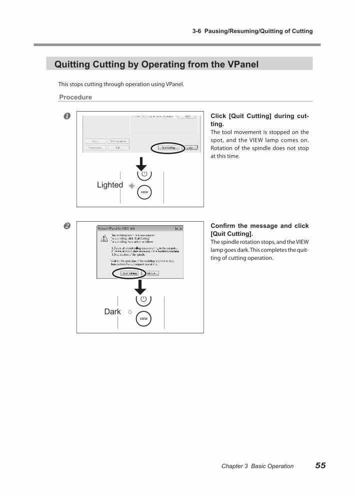
This stops cutting through operation using VPanel.
Procedure
Click [Quit Cutting] during cut-ting.The tool movement is stopped on the spot, and the VIEW lamp comes on. Rotation of the spindle does not stop at this time.
Confirm the message and click [Quit Cutting].The spindle rotation stops, and the VIEW lamp goes dark. This completes the quit-ting of cutting operation.
Dark
Lighted

56

Chapter 4 Getting Ready for and Performing Cutting
This section explains the preparations for cutting such as installing the tool and setting the reference position of the cutting, and the method for outputting the cutting data
4-1 Cutting Area ................................................................ 58
Workpiece Size and Location Where Secured in Place 58
Actual Size That Can Be Cut ......................................... 58
4-2 Installing a Tool ........................................................... 59
Tool Selection ................................................................ 59
Features of the Tools ..................................................... 59
Installing a Tool (End mill) .............................................. 59
4-3 Starting Cutting ........................................................... 61
About Origin Point ......................................................... 61
Setting Origin Point ........................................................ 61
Start Cutting (Output to the machine directly form the applica-tion) ................................................................................ 64
Start Cutting (Output via VPanel) .................................. 65
Recovery of Operation from Emergency Stop or Emergency Shutdown ....................................................................... 67
4-4 Override ...................................................................... 68
What's an Override? ...................................................... 68
How to Make the Settings for Overrides ........................ 68
57
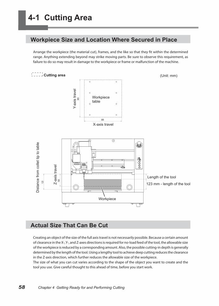
58 Chapter 4 Getting Ready for and Performing CuttingChapter 4 Getting Ready for and Performing Cutting
4-1 Cutting Area
Workpiece Size and Location Where Secured in Place
Arrange the workpiece (the material cut), frames, and the like so that they fit within the determined range. Anything extending beyond may strike moving parts. Be sure to observe this requirement, as failure to do so may result in damage to the workpiece or frame or malfunction of the machine.
Actual Size That Can Be Cut
Creating an object of the size of the full axis travel is not necessarily possible. Because a certain amount of clearance in the X-, Y-, and Z-axes directions is required for no-load feed of the tool, the allowable size of the workpiece is reduced by a corresponding amount. Also, the possible cutting-in depth is generally determined by the length of the tool. Using a lengthy tool to achieve deep cutting reduces the clearance in the Z-axis direction, which further reduces the allowable size of the workpiece.The size of what you can cut varies according to the shape of the object you want to create and the tool you use. Give careful thought to this ahead of time, before you start work.
305
305
105
123
Cutting area
X-axis travel
Y-ax
is tr
avel
Z-ax
is tr
avel
Dis
tanc
e fro
m c
olle
t tip
to ta
ble
(Unit: mm)
123 mm - length of the tool
Workpiece
Workpiece table
Length of the tool
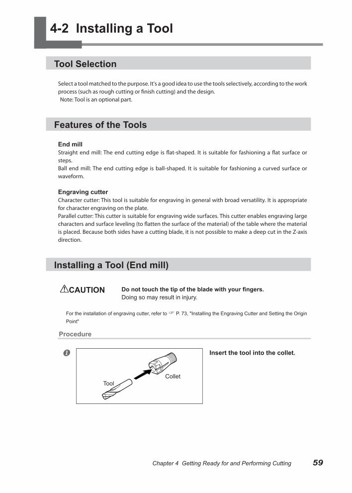
59Chapter 4 Getting Ready for and Performing CuttingChapter 4 Getting Ready for and Performing Cutting
4-2 Installing a Tool
Tool Selection
Select a tool matched to the purpose. It's a good idea to use the tools selectively, according to the work process (such as rough cutting or finish cutting) and the design.Note: Tool is an optional part.
Features of the Tools
End millStraight end mill: The end cutting edge is flat-shaped. It is suitable for fashioning a flat surface or steps.Ball end mill: The end cutting edge is ball-shaped. It is suitable for fashioning a curved surface or waveform.
Engraving cutterCharacter cutter: This tool is suitable for engraving in general with broad versatility. It is appropriate for character engraving on the plate.Parallel cutter: This cutter is suitable for engraving wide surfaces. This cutter enables engraving large characters and surface leveling (to flatten the surface of the material) of the table where the material is placed. Because both sides have a cutting blade, it is not possible to make a deep cut in the Z-axis direction.
Installing a Tool (End mill)
CAUTION Do not touch the tip of the blade with your fingers.Doing so may result in injury.
For the installation of engraving cutter, refer to P. 73, "Installing the Engraving Cutter and Setting the Origin Point"
Procedure
Insert the tool into the collet.
ToolCollet
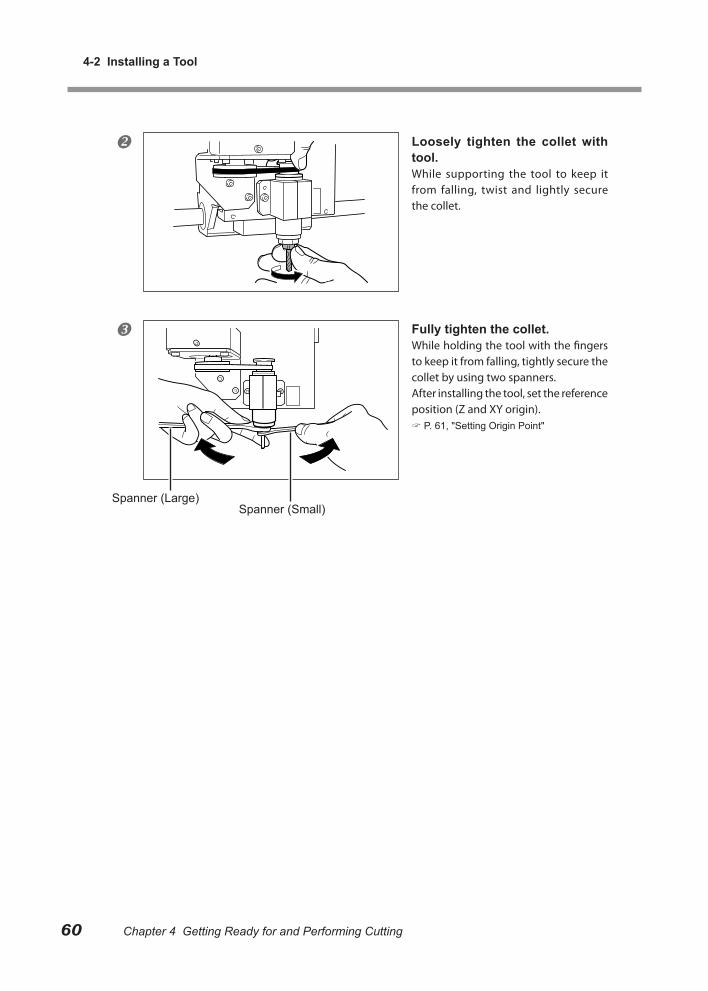
Chapter 4 Getting Ready for and Performing Cutting
4-2 Installing a Tool
60 Chapter 4 Getting Ready for and Performing Cutting Chapter 4 Getting Ready for and Performing Cutting
Loosely tighten the collet with tool.While supporting the tool to keep it from falling, twist and lightly secure the collet.
Fully tighten the collet.While holding the tool with the fingers to keep it from falling, tightly secure the collet by using two spanners.After installing the tool, set the reference position (Z and XY origin). P. 61, "Setting Origin Point"
Spanner (Large)Spanner (Small)
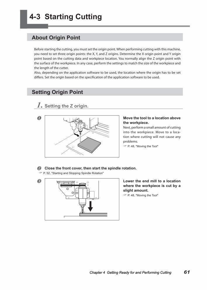
61Chapter 4 Getting Ready for and Performing CuttingChapter 4 Getting Ready for and Performing Cutting Chapter 4 Getting Ready for and Performing Cutting
4-3 Starting Cutting
About Origin Point
Before starting the cutting, you must set the origin point. When performing cutting with this machine, you need to set three origin points: the X, Y, and Z origins. Determine the X origin point and Y origin point based on the cutting data and workpiece location. You normally align the Z origin point with the surface of the workpiece. In any case, perform the settings to match the size of the workpiece and the length of the cutter.Also, depending on the application software to be used, the location where the origin has to be set differs. Set the origin based on the specification of the application software to be used.
Setting Origin Point
1. Setting the Z origin.
Move the tool to a location above the workpiece.Next, perform a small amount of cutting into the workpiece. Move to a loca-tion where cutting will not cause any problems. P. 48, "Moving the Tool"
Close the front cover, then start the spindle rotation. P. 52, "Starting and Stopping Spindle Rotation"
Lower the end mill to a location where the workpiece is cut by a slight amount. P. 48, "Moving the Tool"
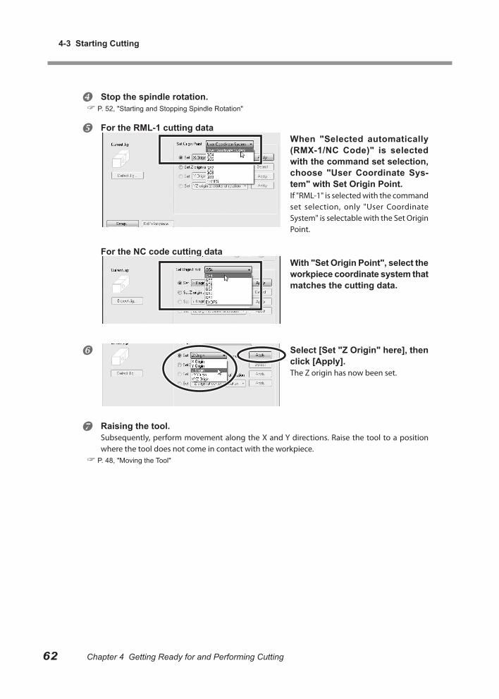
4-3 Starting Cutting
62 Chapter 4 Getting Ready for and Performing Cutting Chapter 4 Getting Ready for and Performing Cutting
Stop the spindle rotation. P. 52, "Starting and Stopping Spindle Rotation"
For the RML-1 cutting dataWhen "Selected automatically (RMX-1/NC Code)" is selected with the command set selection, choose "User Coordinate Sys-tem" with Set Origin Point.If "RML-1" is selected with the command set selection, only "User Coordinate System" is selectable with the Set Origin Point.
For the NC code cutting dataWith "Set Origin Point", select the workpiece coordinate system that matches the cutting data.
Select [Set "Z Origin" here], then click [Apply].The Z origin has now been set.
Raising the tool.Subsequently, perform movement along the X and Y directions. Raise the tool to a position where the tool does not come in contact with the workpiece.
P. 48, "Moving the Tool"
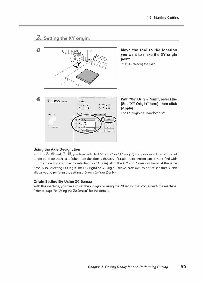
Chapter 4 Getting Ready for and Performing Cutting
4-3 Starting Cutting
63Chapter 4 Getting Ready for and Performing Cutting
2. Setting the XY origin.
Move the tool to the location you want to make the XY origin point. P. 48, "Moving the Tool"
With "Set Origin Point", select the [Set "XY Origin" here], then click [Apply].The XY origin has now been set.
Using the Axis DesignationIn steps 1.- and 2.-, you have selected "Z origin" or "XY origin", and performed the setting of origin point for each axis. Other than the above, the axis of origin point setting can be specified with this machine. For example, by selecting [XYZ Origin], all of the X, Y, and Z axes can be set at the same time. Also, selecting [X Origin] (or [Y Origin] or [Z Origin]) allows each axis to be set separately, and allows you to perform the setting of X only (or Y or Z only).
Origin Setting By Using Z0 SensorWith this machine, you can also set the Z origin by using the Z0 sensor that comes with the machine. Refer to page 70 "Using the Z0 Sensor" for the details.
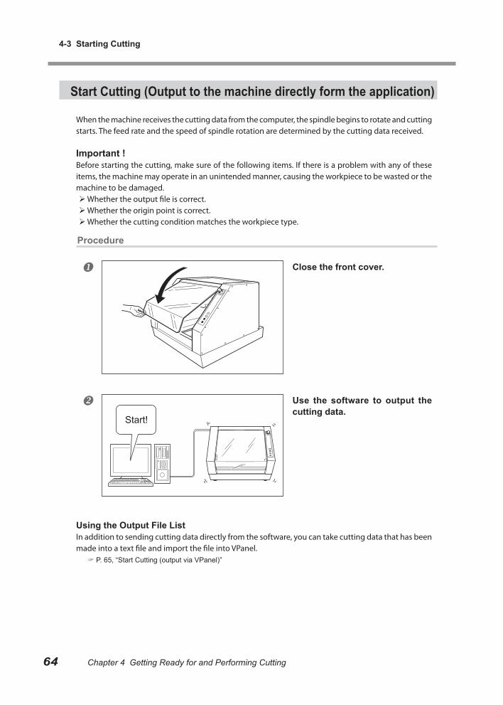
4-3 Starting Cutting
64 Chapter 4 Getting Ready for and Performing Cutting Chapter 4 Getting Ready for and Performing Cutting
Start Cutting (Output to the machine directly form the application)
When the machine receives the cutting data from the computer, the spindle begins to rotate and cutting starts. The feed rate and the speed of spindle rotation are determined by the cutting data received.
Important !Before starting the cutting, make sure of the following items. If there is a problem with any of these items, the machine may operate in an unintended manner, causing the workpiece to be wasted or the machine to be damaged. Whether the output file is correct. Whether the origin point is correct. Whether the cutting condition matches the workpiece type.
Procedure
Close the front cover.
Use the software to output the cutting data.
Using the Output File ListIn addition to sending cutting data directly from the software, you can take cutting data that has been made into a text file and import the file into VPanel.
P. 65, “Start Cutting (output via VPanel)”
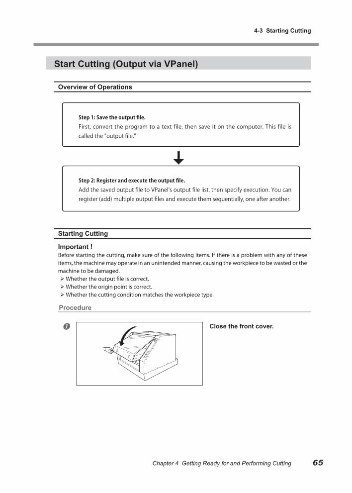
Chapter 4 Getting Ready for and Performing Cutting
4-3 Starting Cutting
65Chapter 4 Getting Ready for and Performing Cutting
Start Cutting (Output via VPanel)
Overview of Operations
Starting Cutting
Important !Before starting the cutting, make sure of the following items. If there is a problem with any of these items, the machine may operate in an unintended manner, causing the workpiece to be wasted or the machine to be damaged. Whether the output file is correct. Whether the origin point is correct. Whether the cutting condition matches the workpiece type.
Procedure
Close the front cover.
Step 1: Save the output file.
First, convert the program to a text file, then save it on the computer. This file is called the "output file."
Step 2: Register and execute the output file.
Add the saved output file to VPanel's output file list, then specify execution. You can register (add) multiple output files and execute them sequentially, one after another.
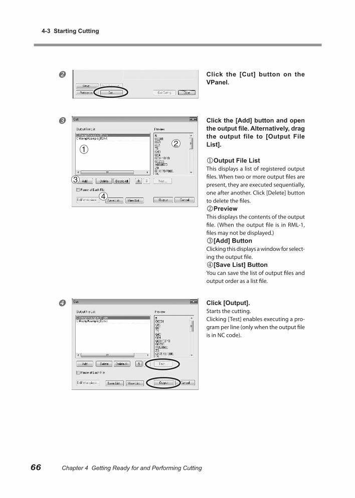
4-3 Starting Cutting
66 Chapter 4 Getting Ready for and Performing Cutting Chapter 4 Getting Ready for and Performing Cutting
Click the [Cut] button on the VPanel.
Click the [Add] button and open the output file. Alternatively, drag the output file to [Output File List].
Output File ListThis displays a list of registered output files. When two or more output files are present, they are executed sequentially, one after another. Click [Delete] button to delete the files.PreviewThis displays the contents of the output file. (When the output file is in RML-1, files may not be displayed.)[Add] ButtonClicking this displays a window for select-ing the output file.[Save List] ButtonYou can save the list of output files and output order as a list file.
Click [Output].Starts the cutting.Clicking [Test] enables executing a pro-gram per line (only when the output file is in NC code).

Chapter 4 Getting Ready for and Performing Cutting
4-3 Starting Cutting
67Chapter 4 Getting Ready for and Performing Cutting
Recovery of Operation from Emergency Stop or Emergency Shutdown
If an emergency stop or an emergency shutdown occurs during cutting, remove the tool and the workpiece from the machine. When the operation resumes, initialization is performed on the machine. At this time, the tool and the workpiece may collide depending on the position in which the tool and workpiece stopped, which can cause damage to the machine while restarting.
P. 43, "Starting and Quitting"
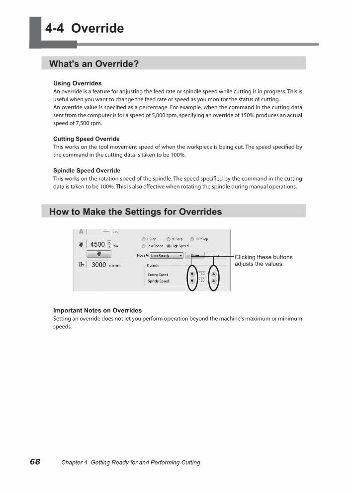
68 Chapter 4 Getting Ready for and Performing Cutting
4-4 Override
What's an Override?
Using OverridesAn override is a feature for adjusting the feed rate or spindle speed while cutting is in progress. This is useful when you want to change the feed rate or speed as you monitor the status of cutting.An override value is specified as a percentage. For example, when the command in the cutting data sent from the computer is for a speed of 5,000 rpm, specifying an override of 150% produces an actual speed of 7,500 rpm.
Cutting Speed OverrideThis works on the tool movement speed of when the workpiece is being cut. The speed specified by the command in the cutting data is taken to be 100%.
Spindle Speed OverrideThis works on the rotation speed of the spindle. The speed specified by the command in the cutting data is taken to be 100%. This is also effective when rotating the spindle during manual operations.
How to Make the Settings for Overrides
Important Notes on OverridesSetting an override does not let you perform operation beyond the machine's maximum or minimum speeds.
Clicking these buttons adjusts the values.

Chapter 5 Appendix
This section explains how to use the engraving cutter as well as the maintenance method, countermeasures against the problems, and the specifications of the machine.
5-1 Using the Z0 Sensor ................................................... 70
What’s a Z0 Sensor ....................................................... 70
Setting the Z Origin Using the Z0 Sensor ...................... 70
Setting the Thickness of the Z0 Sensor ......................... 72
5-2 Using the Engraving Cutter......................................... 73
Installing the Engraving Cutter and Setting the Origin Point .............................................................................. 73
5-3 Maintenance ............................................................... 76
Cleaning ........................................................................ 76
Maintenance of the Spindle Unit.................................... 77
5-4 What to Do If... ............................................................ 78
5-5 Responding to an Error Message ............................... 83
5-6 Power Rating and Serial Number Locations ............... 86
5-7 NC Code Specifications .............................................. 87
Word List ....................................................................... 89
5-8 Specifications .............................................................. 91
Expansion Connector .................................................... 91
External View ................................................................. 92
Dimensional Drawings of the Table Area ....................... 93
Main Specifications ........................................................ 94
System Requirements for USB Connection .................. 95
69
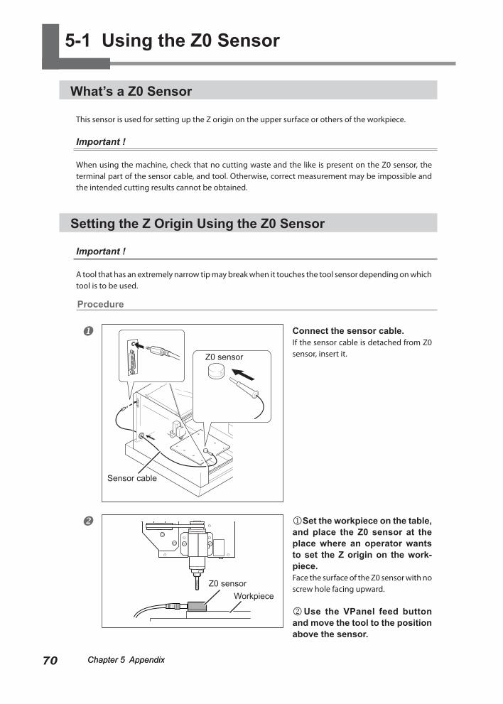
Chapter 5 Appendix Chapter 5 Appendix70 Chapter 5 Appendix Chapter 5 Appendix
5-1 Using the Z0 Sensor
What’s a Z0 Sensor
This sensor is used for setting up the Z origin on the upper surface or others of the workpiece.
Important !
When using the machine, check that no cutting waste and the like is present on the Z0 sensor, the terminal part of the sensor cable, and tool. Otherwise, correct measurement may be impossible and the intended cutting results cannot be obtained.
Setting the Z Origin Using the Z0 Sensor
Important !
A tool that has an extremely narrow tip may break when it touches the tool sensor depending on which tool is to be used.
Procedure
Connect the sensor cable.If the sensor cable is detached from Z0 sensor, insert it.
Set the workpiece on the table, and place the Z0 sensor at the place where an operator wants to set the Z origin on the work-piece.Face the surface of the Z0 sensor with no screw hole facing upward.
Use the VPanel feed button and move the tool to the position above the sensor.
Z0 sensor
Sensor cable
WorkpieceZ0 sensor
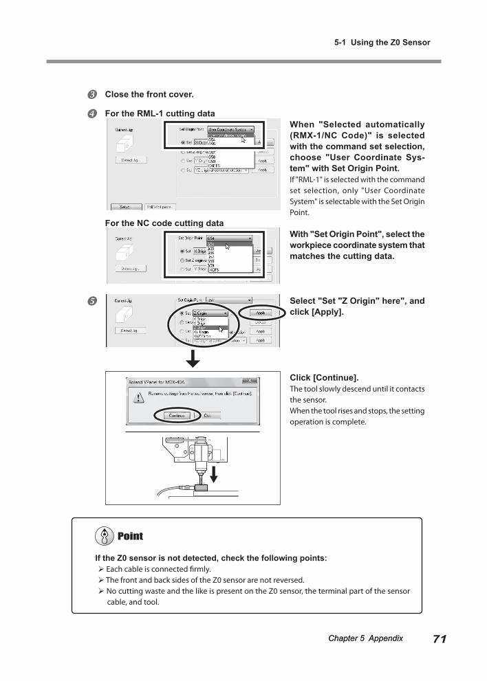
Chapter 5 Appendix
5-1 Using the Z0 Sensor
71Chapter 5 AppendixChapter 5 Appendix Chapter 5 Appendix
Close the front cover.
For the RML-1 cutting dataWhen "Selected automatically (RMX-1/NC Code)" is selected with the command set selection, choose "User Coordinate Sys-tem" with Set Origin Point.If "RML-1" is selected with the command set selection, only "User Coordinate System" is selectable with the Set Origin Point.
For the NC code cutting dataWith "Set Origin Point", select the workpiece coordinate system that matches the cutting data.
Select "Set "Z Origin" here", and click [Apply].
Click [Continue].The tool slowly descend until it contacts the sensor.When the tool rises and stops, the setting operation is complete.
If the Z0 sensor is not detected, check the following points: Each cable is connected firmly. The front and back sides of the Z0 sensor are not reversed. No cutting waste and the like is present on the Z0 sensor, the terminal part of the sensor
cable, and tool.
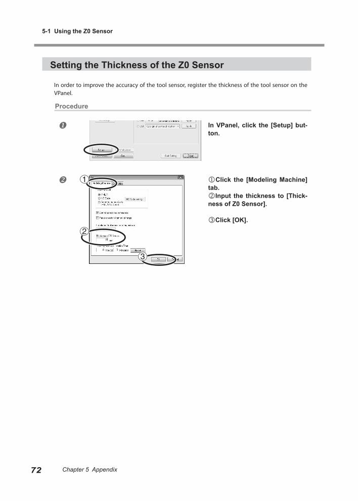
Chapter 5 Appendix
5-1 Using the Z0 Sensor
72 Chapter 5 Appendix Chapter 5 Appendix
Setting the Thickness of the Z0 Sensor
In order to improve the accuracy of the tool sensor, register the thickness of the tool sensor on the VPanel.
Procedure
In VPanel, click the [Setup] but-ton.
Click the [Modeling Machine] tab.Input the thickness to [Thick-ness of Z0 Sensor].
Click [OK].
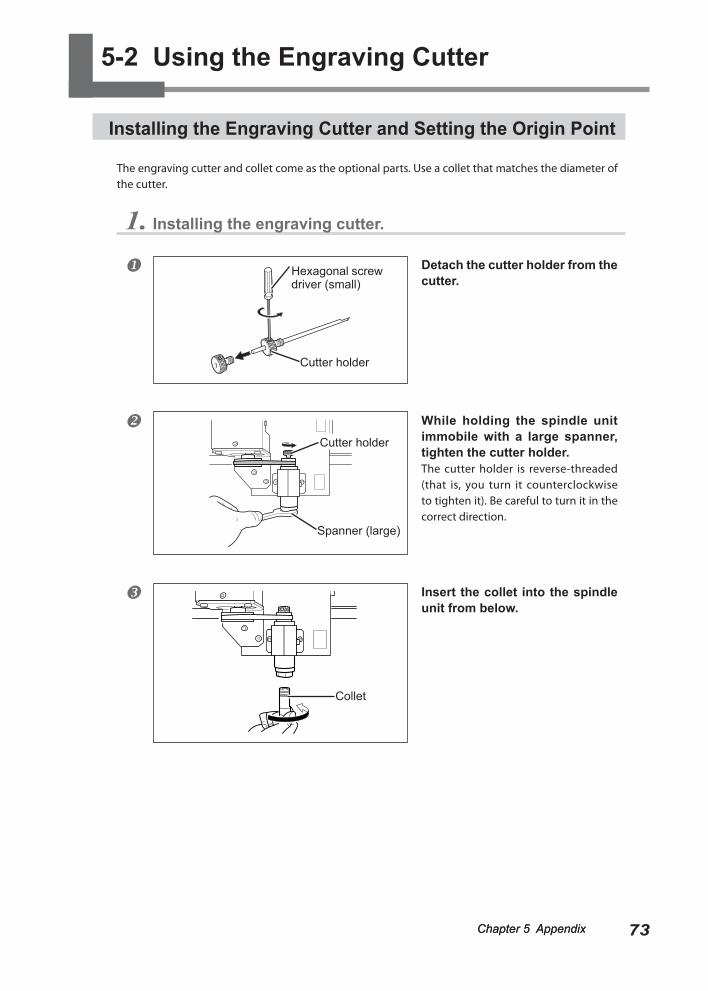
73Chapter 5 AppendixChapter 5 Appendix Chapter 5 Appendix
5-2 Using the Engraving Cutter
Installing the Engraving Cutter and Setting the Origin Point
The engraving cutter and collet come as the optional parts. Use a collet that matches the diameter of the cutter.
1. Installing the engraving cutter.
Detach the cutter holder from the cutter.
While holding the spindle unit immobile with a large spanner, tighten the cutter holder.The cutter holder is reverse-threaded (that is, you turn it counterclockwise to tighten it). Be careful to turn it in the correct direction.
Insert the collet into the spindle unit from below.
Cutter holder
Hexagonal screw driver (small)
Spanner (large)
Collet
Cutter holder
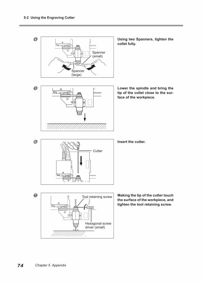
5-2 Using the Engraving Cutter
74 Chapter 5 Appendix Chapter 5 Appendix
Using two Spanners, tighten the collet fully.
Lower the spindle and bring the tip of the collet close to the sur-face of the workpiece.
Insert the cutter.
Making the tip of the cutter touch the surface of the workpiece, and tighten the tool retaining screw.
Cutter
Tool retaining screw
Hexagonal screw driver (small)
Spanner (large)
Spanner (small)
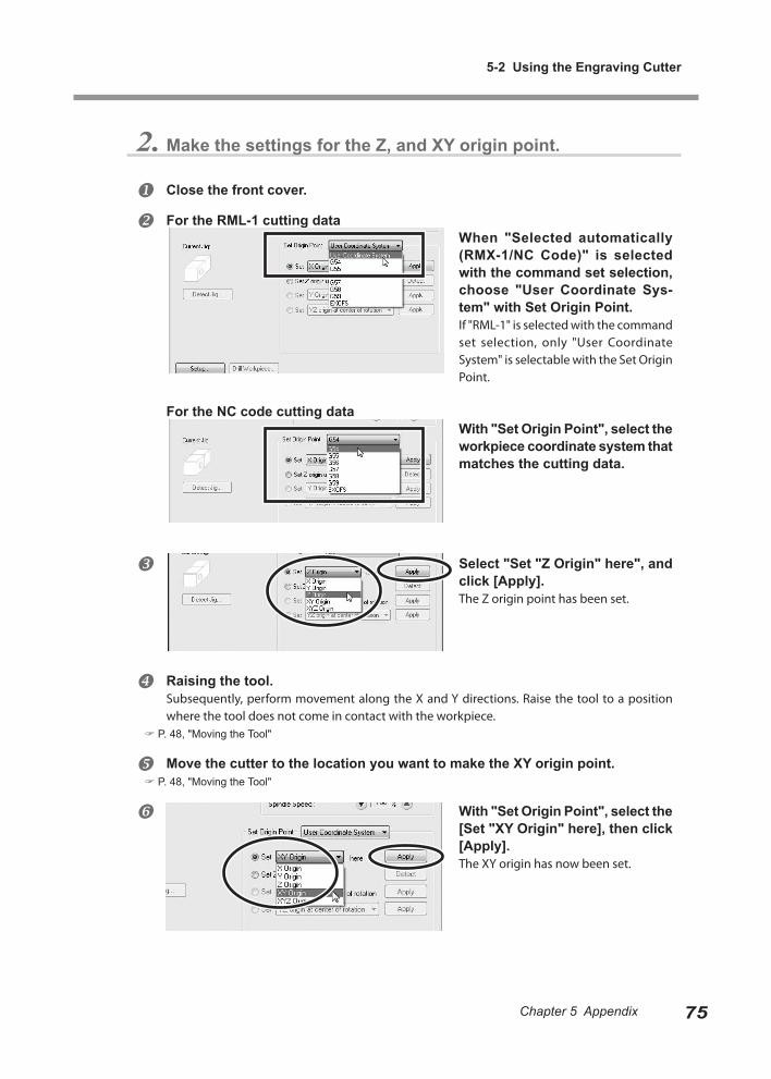
Chapter 5 Appendix
5-2 Using the Engraving Cutter
75Chapter 5 Appendix
2. Make the settings for the Z, and XY origin point.
Close the front cover.
For the RML-1 cutting dataWhen "Selected automatically (RMX-1/NC Code)" is selected with the command set selection, choose "User Coordinate Sys-tem" with Set Origin Point.If "RML-1" is selected with the command set selection, only "User Coordinate System" is selectable with the Set Origin Point.
For the NC code cutting dataWith "Set Origin Point", select the workpiece coordinate system that matches the cutting data.
Select "Set "Z Origin" here", and click [Apply].The Z origin point has been set.
Raising the tool.Subsequently, perform movement along the X and Y directions. Raise the tool to a position where the tool does not come in contact with the workpiece.
P. 48, "Moving the Tool"
Move the cutter to the location you want to make the XY origin point. P. 48, "Moving the Tool"
With "Set Origin Point", select the [Set "XY Origin" here], then click [Apply].The XY origin has now been set.
Chapter 5 Appendix Chapter 5 Appendix76 Chapter 5 Appendix Chapter 5 Appendix
5-3 Maintenance
Cleaning
WARNING Never use a pneumatic blower.This machine is not compatible with a pneumatic blower. Cutting waste may get inside the machine and cause fire or electrical shock.
WARNING Never use a solvent such as gasoline, alcohol, or thinner to perform cleaning.Doing so may cause fire.
WARNING Disconnect the power cord before performing cleaning or mainte-nance.Attempting such operations while the machine is connected to a power source may result in injury or electrical shock.
WARNING When using a vacuum cleaner to take up cutting waste, exercise caution to prevent fire or dust explosion.Taking up fine cuttings using an ordinary vacuum cleaner may cause danger of fire or explosion. Check with the manufacturer of the vacuum cleaner. When the safety of use cannot be determined, clean using a brush or the like, without using the vacuum cleaner.
CAUTION Caution: high temperatures.The cutting tool and spindle motor become hot. Exercise caution to avoid fire or burns.
CAUTION When performing maintenance, be sure to keep the cutter de-tached.Contact with the blade may cause injury.
This machine is a precision device. Carry out daily care and maintenance. Carefully clean away cutting waste. Operating the machine with a large amount of cutting waste
present may cause malfunction. Never apply silicone substances (oil, grease, spray, etc.) to the machine. Doing so may cause poor
switch contact. Never apply lubrication.
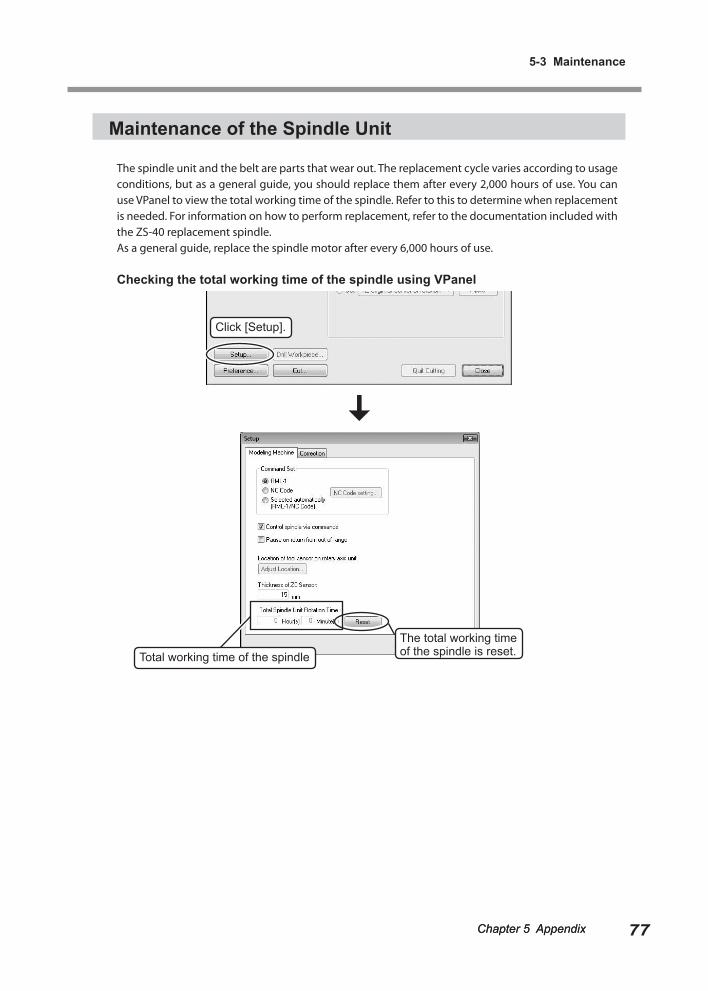
Chapter 5 Appendix
5-3 Maintenance
77Chapter 5 AppendixChapter 5 Appendix Chapter 5 Appendix
Maintenance of the Spindle Unit
The spindle unit and the belt are parts that wear out. The replacement cycle varies according to usage conditions, but as a general guide, you should replace them after every 2,000 hours of use. You can use VPanel to view the total working time of the spindle. Refer to this to determine when replacement is needed. For information on how to perform replacement, refer to the documentation included with the ZS-40 replacement spindle.As a general guide, replace the spindle motor after every 6,000 hours of use.
Checking the total working time of the spindle using VPanel
The total working time of the spindle is reset.
Click [Setup].
Total working time of the spindle
Chapter 5 Appendix Chapter 5 Appendix78 Chapter 5 Appendix Chapter 5 Appendix
5-4 What to Do If...
The Power Does Not Come On.
Has the Emergency Stop button been pressed?When the Emergency Stop button is pressed, the power does not come on. Release the Emergency Stop button.
P. 42, "To Cancel an Emergency Stop"
Initialization is Not Performed or Initialization Fails.
Is a front cover open?When starting the machine, close the front cover. For safety, initialization is not performed when a cover remains open at startup.
Is a large amount of cutting waste pres-ent?Clean away any cutting waste. Clean the area around the spindle head especially carefully.
P. 76, "Maintenance"
Is anything caught on the spindle head or table?Check whether something has become caught and is impeding initialization.
VPanel Doesn't Start Correctly.
Has initialization been completed?Before you start VPanel, first switch on the power to the machine.
P. 43, "Starting and Quitting"
Is the computer connected?Check whether the connector cable has come loose.
Is the driver installed correctly?If the connection to the computer is not made in the sequence described, the driver may fail to be installed correctly. VPanel does not function normally when driver is misconfigured. Check again to ensure that the connection was made using the correct procedure.
P. 38, "Installing the Windows-based Driver"
Are two or more machines connected to a single computer?VPanel cannot control more than one machine at the same time. Never connect two or more instances of this machine to a single computer.
Operations are Ignored.
Is the cable connected?Connect the cable securely.
P. 34, "Cable Connections"
Was the machine started according to the correct procedure?Simply switching on the main power does not en-able operation. Start the machine using the correct procedure.
P. 43, "Starting and Quitting"
Is a front cover open?This machine restricts some operations when a front cover is open. Close the front cover.
Is the VIEW lamp on?Press and hold the VIEW button to cancel the paused state.
Is the lamps flashing an error message? P. 80, “What to Do If a Flashing Error Is Displayed."”
Is a large amount of cutting waste pres-ent?Clean away any cutting waste. Clean the area around the spindle head especially carefully.
P. 76, "Maintenance"
Is the driver installed correctly?If the connection to the computer is not made in the sequence described, the driver may fail to be installed correctly. VPanel does not function normally when driver is misconfigured. Check again to ensure that the connection was made using the correct procedure.
P. 38, "Installing the Windows-based Driver"
Chapter 5 Appendix
5-4 What to Do If...
79Chapter 5 AppendixChapter 5 Appendix Chapter 5 Appendix
Are two or more machines connected to a single computer?VPanel cannot control more than one machine at the same time. Never connect two or more instances of this machine to a single computer.
Is VPanel displaying an error message? P. 83, "Responding to an Error Message"
The Spindle Doesn't Rotate.
Is a front cover open?For safety, the spindle does not rotate when a front cover is open. Close the front cover.
Is a large amount of cutting waste pres-ent?Clean away any cutting waste. Clean the area around the spindle head especially carefully.
P. 76, "Maintenance"
Has a setting been made to keep the spindle from rotating?In VPanel, click the [Setup], then click the [Modeling Machine] tab. Here, select the [Control spindle via commands] check box.
Abnormal Cutting is Performed.
Is the location of the origin set correctly?Check whether the origin has been set correctly. An incorrect origin location may result in cutting at an unintended position.
P. 61, “About Origin Point,” “Setting Origin Point”
Is the command set correct?Make sure the appropriate command set for the program you're using has been selected. An incor-rect command mode may lead to errors, unintended
operation, or no operation.
P. 46, “Selecting the Command Set”
The Origin is Misaligned.
Is the correct workpiece coordinate system selected?In the NC program, there are six coordinate systems. Depending on which coordinate system is used, the position of the origin differs. For instance, if the NC program uses G55, the origins must be set relative to workpiece coordinate system G55.
P. 61, “Setting Origin Point,” and "NC Code Reference
Manual"
Has the EXOFS setting been made?The EXOFS in the NC code have a function to shift the origin. Set EXOFS to zero, then redo the settings for the origins. If the origin is still shifted, check the program.How to set EXOFS to zero:1. Select [Machine Coordinate System] from the display of
the coordinate system on the VPanel.
2. Move the tool position to “X: 0”, “Y: 0”, “Z: 0.”
3. Select [EXOFS] at the [Setting Reference Point].
4. Select [Set “XYZ origin” here] from [Set Origin Point] and
click [Apply].
P. 46 “Selecting the Command Set,” and p. 48, “Moving
the Tool”
The Feed Rate or Spindle Speed is Wrong.
Has an override been set?An override changes the feed rate or spindle rotation speed. Check the settings for overrides. Unless you have a special reason for changing them, leave all overrides set at 100%.
P. 68, “Override”
The Cutting Results are Not Attractive.
Is the cutting condition optimal?The optimal cutting parameters are determined by a balance of such factors as the hardness of the ma-terial, the feed rate, the spindle rotating speed, the cutting-in depth, and the capacity of the tool. Refer to the results and try fine tuning the parameters.
5-4 What to Do If...
80 Chapter 5 Appendix Chapter 5 Appendix
Is the tool firmly secured in place?Retighten the collet to secure in place firmly.
P. 59, "Installing a Tool," p. 73, "Installing the Engraving
Cutter and Setting the Origin Point"
Is the tool tip worn?If the tip of the tool is worn, replace with a new tool.
What to Do If a Flashing Error Is Displayed
If the lamps are flashing as shown below, then an error has occurred on the machine. To correct the error, follow the steps de-scribed below.
The MODELING and SCANNING lamps
An error occurred during initialization of the machine.Switch the power off, then back on. If the error is not cleared when you switch the power on again, the machine may be malfunctioning. Contact your authorized Roland DG Corp. dealer.
The MODELING and VIEW lamps
A front cover was opened during cutting or spindle rotation.Operation cannot be continued. Close the front cover and press the sub power button.
The MODELING lamp
The spindle motor error occurred.Operation cannot be continued. Press the sub power button to clear the error. Make the program's cutting parameters more relaxed to lessen the load applied to the spindle.
Installation is Impossible
If installation quits partway through, or if the wizard does not appear when you make the connection with a USB cable, take action as follows.
Windows 7 1. If the [Found New Hardware] appears, click [Cancel] to close it. Disconnect any USB cables for printers or other such equipment other than this machine. 2. Click the [Start] menu, then right-click [Computer]. Click [Properties]. 3. Click [Device Manager]. The [User Account Con-trol] appears, click [Continue]. The [Device Manager] ape-pears. 4. At the [View] menu, click [Show hidden devices]. 5. In the list, find [Other device], then double-click it. When the model name you are using or [Unknown device] appears below the item you selected, click it to choose it. 6. Go to the [Action] menu, and click [Uninstall]. 7. In "Confirm Device Uninstall" window, select [De-late the driver software for this device.], then click [OK]. Close the [Device Manager]. 8. Detach the USB cable connected to the printer, and the restart Windows. 9. Uninstall the driver. Carry out the steps from step 3 in page 81 “Uninstall the Driver Windows 7” to un-install the driver. 10. Install the driver again according to the procedure in page 38 “Installing the Windows-based Driver”
Windows Vista1. If the [Found New Hardware] appears, click [Cancel] to close it. Disconnect any USB cables for printers or other such equipment other than this machine.2. Click the [Start] menu, then right-click [Computer]. Click [Properties].3. Click [Device Manager]. The [User Account Control] appears, click [Continue]. The [Device Manager] ap-pears.4. At the [View] menu, click [Show hidden devices].5. In the list, find [Printers] or [Other device], then double-click it. When the model name you are using or [Unknown device] appears below the item you selected, click it to choose it.6. Go to the [Action] menu, and click [Uninstall].
Chapter 5 Appendix
5-4 What to Do If...
81Chapter 5 Appendix
7. In "Confirm Device Uninstall" window, select [De-lete the driver software for this device.], then click [OK]. Close the [Device Manager].8. Detach the USB cable connected to the printer, and the restart Windows.9. Uninstall the driver. Carry out the steps from step 3 in page 81 “Uninstall the Driver Windows Vista” to uninstall the driver.10. Install the driver again according to the procedure in page 38 “Installing the Windows-based Driver.”
Windows XP1. If the [Found New Hardware Wizard] appears, click [Finish] to close it. Disconnect any USB cables for printers or other such equipment other than this machine.2. Click the [Start] menu, then right-click [My Com-puter]. Click [Properties].3. Click the [Hardware] tab, then click [Device Man-ager]. The [Device Manager] appears.4. At the [View] menu, click [Show hidden devices].5. In the list, find [Printers] or [Other device], then double-click it. When the model name you are using or [Unknown device] appears below the item you selected, click it to choose it.6. Go to the [Action] menu, and click [Uninstall].7. In "Confirm Device Uninstall" window, click [OK].8. Close the [Device Manager] and click [OK].9. Detach the USB cable connected to the printer, and the restart Windows.10. Uninstall the driver. Carry out the steps from step 3 in page 82 “Uninstall the Driver Windows XP” to uninstall the driver.11. Install the driver again according to the procedure in page 38 “Installing the Windows-based Driver.”
Uninstalling the Driver
When uninstalling the driver, perform following operation.
Windows 7 1. Before you start uninstallation of the driver, unplug the USB cables from your computer. 2. Log on to Windows as “Administrators” right. 3. From the [Start] menu, click [Control Panel]. Click [Uninstall a program].
4. Click the driver for the machine to delete to select it, then Click [Uninstall]. 5. A message prompting you to confirm deletion appears. Click [Yes]. 6. From the [Start] menu, choose [All Programs], then [Accessories], then [Run], and then click [Browse]. 7. Choose the name of the drive or folder where the driver is located. (*) 8. Select "SETUP.EXE" and click [Open], then click [OK]. 9. The [User Account Control] appears, click [Al-low]. 10. The Setup program for the driver starts. 11. Click [Uninstall] to choose it. Select the machine to delete, then click [Start]. 12. If it is necessary to restart your computer, a win-down prompting you to restart it appears. Click [Yes]. 13. The uninstallation finishes after the computer restarts.
(*) When using the CD-ROM, specify the folder as shown below (assuming your CD-ROM drive is the D drive). D:\Drivers\25D\WIN7 If you're not using the CD-ROM, go to the Roland DG Corp. website (http://www.rolanddg.com/) and download the driver for the machine you want to delete, then specify the folder where you want to expand the downloaded file.
Windows Vista1. Before you start uninstallation of the driver, unplug the USB cables from your computer.2. Log on to Windows as “Administrators” right.3. From the [Start] menu, click [Control Panel]. From the [Hard-ware and Sound] group, click [Printer]. [Printer] folder opens.4. Click the model name’s icon you are using. From the [Organize] menu, click [Delete]. The [User Account Control] appears, click [Continue].5. A message prompting you to confirm deletion appears. Click [Yes].6. In the [Printers] folder, right-click any location where no printer icon is present. From the [Run as administrator] menu, select [Server Properties]. The [User Account Control] appears, click [Continue].7. Click the [Drivers] tab, then from the [Installed printer drivers] list, choose the machine to delete. Click [Remove].
Chapter 5 Appendix
5-4 What to Do If...
82 Chapter 5 Appendix Chapter 5 Appendix
8. The [Remove Driver And Package] appears, select [Remove driver and driver package]. Click [OK].9. When the prompt message appears, click [Yes].10. The package and driver to delete are displayed. Make sure that what is displayed is the machine you want to delete, then click [Delete].11. The items that have been deleted are displayed. Click [OK].12. Click [Close] on [Remove Driver And Package] window.13. From the [Start] menu, choose [All Programs], then [Accessories], then [Run], and then click [Browse].14. Choose the name of the drive or folder where the driver is located. (*)15. Select "SETUP.EXE" and click [Open], then click [OK].16. The [User Account Control] appears, click [Al-low].17. The Setup program for the driver starts.18. Click [Uninstall] to choose it. Select the machine to delete, then click [Start].19. If it is necessary to restart your computer, a win-dow prompting you to restart it appears. Click [Yes].20. The uninstallation finishes after the computer restarts.
(*) When using the CD-ROM, specify the folder as shown below (assuming your CD-ROM drive is the D drive).D:\Drivers\25D\WINVISTAIf you're not using the CD-ROM, go to the Roland DG Corp. website (http://www.rolanddg.com/) and download the driver for the machine you want to delete, then specify the folder where you want to expand the downloaded file.
Windows XP1. Before you start uninstallation of the driver, unplug the USB cables from your computer.2. Log on to Windows as “Administrators” right.3. From the [Start] menu, click [Control Panel]. Click [Printers and Other Hardware], then click [Printers and Faxes].4. Click the model name’s icon you are using. From the [File] menu, choose [Delete].5. A message prompting you to confirm deletion appears. Click [Yes].
6. Go to [File] and select [Server Properties].7. Click the [Driver] tab, then from the [Installed printer drivers] list, choose the machine to delete.8. Click [Delete]. When the prompt message appears, click [Yes].9. From the [Start] menu, select [Run], then click [Browse].10. From the [File Locations] list, choose the name of the drive or folder where the driver is located. (*)11. Select "SETUP.EXE" and click [Open], then click [OK].12. The Setup program for the driver starts.13. Click [Uninstall] to choose it. Select the machine to delete, then click [Start].14. If it is necessary to restart your computer, a win-dow prompting you to restart it appears. Click [Yes].15. The uninstallation finishes after the computer restarts.
(*) When using the CD-ROM, specify the folder as shown below (assuming your CD-ROM drive is the D drive).D:\Drivers\25D\WIN2KXPIf you're not using the CD-ROM, go to the Roland DG Corp. web-site (http://www.rolanddg.com/) and download the driver for the machine you want to delete, then specify the folder where you want to expand the downloaded file.
83Chapter 5 AppendixChapter 5 Appendix Chapter 5 Appendix
5-5 Responding to an Error Message
This section describes the error messages that may appear on the monitor of the com-puter you're using, and how to take action to remedy the problem. If the action described here does not correct the problem, or if an error message not described here appears, contact your authorized Roland DG Corp. dealer.
For Connection of Equipment
Click [OK]. The machine may have accidentally been switched off, or the connector cable may have come loose. After checking, restart the machine.
P. 43, "Starting and Quitting"
Click [Quit], then restart the machine and redo the operation from the beginning.
P. 43, "Starting and Quitting"
The error message appeared because the Z0 sensor was not connected when performing an operation that required the Z0 sensor. Click [OK]. Connect the Z0 sensor, and perform the operation again. If this mes-sage persists even after the Z0 sensor is connected, the error may be caused by a faulty connection or open circuit. In such cases, contact your authorized Roland DG Corp. dealer.
P. 70, "Using the Z0 Sensor"
No response is returned from ma-chine.Make sure that the connection cable is connected securely and the machine is switched on.
No modeling machine was found.If the power is off, then switch it on.If the cable is unconnected, then con-nect it.
The sensor cable is not connected to the machine.
Detection Failure
With the operation that uses the Z0 sensor, which utilizes flow of electricity, the detection operation failed because factors occurred that blocked the flow of electricity. Possible causes include the disconnec-tion of Z0 sensor or dust of tool or Z0 sensor caused by cutting waste. If these parts are not free of dust, the sensor does not respond correctly. Clean away any dust first, and then perform the operation again. If detection still fails even after the connection is made or dust is cleaned, the failure may be caused by mechanical failures such as a cable disconnection. In such cases, contact your authorized Roland DG Corp. dealer.
P. 43, "Starting and Quitting," p. 70, "Using the Z0 Sen-
sor"
Pause
Operation was paused because a command error occurred. Click [Quit] to quit cutting. Cutting can be resumed by clicking [Continue], but doing so is very
The detection operation can not be started.
The detection operation was failed.
The MDX-40A is paused. -- Command Error (name of com-mand set)Ignoring this error and continuing cut-ting is possible, but subsequent results are not assured.Quitting cutting is strongly recom-mended.
If command does not match the ma-chine's command set, select correct command set.
5-5 Responding to an Error Message
84 Chapter 5 Appendix Chapter 5 Appendix
likely to result in unintended operation and is not recommended.The selection of command set may be incorrect. Make sure that the command set of cutting data and the command set selected in VPanel agree with each other. If the error occurs even when the selection of command set is correct, an unknown command may be contained in the cutting data. Check and correct the commands of cutting data.When "Selected automatically (RML-1/NC Code)" is selected with the command set selection, the name of command set does not appear in the error mes-sage.
P. 46, "Selecting the Command Set"
Emergency Stop
An emergency stop occurred because a front cover was opened during cutting or spindle rotation. Fol-low the on-screen messages to switch off the power, close the front cover, and redo the operation from the beginning.
P. 43, "Starting and Quitting"
The MDX-40A has performed an emer-gency stop. -- Cover opened during operation.Operation cannot be continued.To recover from an emergency stop, the power to the equipment must be reset.Carry out the following steps in the se-quence shown.1. Stop any output of cutting data from the CAM or other program.2. Switch the equipment off, then back on.3. Click the [OK] button for this mes-sage.
An emergency stop occurred because of a failure in initialization or the like. The operation cannot be resumed immediately. The message indicating the cause of the error, as well as the causes of the emer-gency stop and the countermeasures are described below. If this message persists even after each of the countermeasures is implemented, turn the main power OFF, and contact your authorized Roland DG Corp. dealer.
*-Limit switch not found.An emergency stop occurred because initialization failed. Switch the power off, remove any cutting waste or other obstructions impeding operation of the spindle head, then redo the operation from the start.*: "X," "Y," "Z," or "A" ("A" is indicated only when the optional ZCL-40A is connected.)
The NVRAM could not be accessed.An emergency stop occurred because the machine's memory unit became partially inaccessible. Follow the on-screen messages to switch off the power and redo the operation from the beginning.
The spindle motor is not connected.A communication error occurred in the spindle control firmware.An unknown error occurred in the spindle control firmware.
An emergency stop occurred because of an error in spindle control. Follow the on-screen messages to
The MDX-40A has performed an emer-gency stop. -- (The message indicating the cause of the error)Switch the equipment off, then back on.If the symptom persists, a malfunction may have occurred. Switch off the equipment's main power and contact your local vendor or Roland sales center.
Chapter 5 Appendix
5-5 Responding to an Error Message
85Chapter 5 Appendix
switch off the power and redo the operation from the beginning.
P. 43, "Starting and Quitting"
An emergency stop occurred because a spindle-mo-tor error occurred. The operation cannot be resumed immediately. The message indicating the cause of the error, as well as the causes of the emergency stop and the countermeasures are described below.
The spindle motor experienced exces-sive current.Spindle rotation is impossible because voltage is too low.The Z motor experienced an excessive load.
This is caused by prolonged high load on the motor or by excessive torque being applied momentarily. Follow the on-screen messages to switch off the power. The cutting may have exceeded the capacity of the machine. Before restarting, revise the cutting conditions. Also, allow the machine to rest for some time, because the motor may have overheated. If messages like these persist, contact your authorized Roland DG Corp. dealer or Roland DG Corp.
P. 43, "Starting and Quitting"
The MDX-40A has performed an emer-gency stop. -- (The message indicating the cause of the error)Switch the equipment power off, then back on.To prevent recurrence, revise the cutting parameters.
An emergency stop occurred because the machine experienced load that exceeded its capacity. The operation cannot be resumed immediately. The message indicating the cause of the error, as well as the causes of the emergency stop and the counter-measures are described below.
The spindle control circuit is running hot.The spindle motor is running hot.
This is caused by prolonged high load on the motor or by excessive torque being applied momentarily. Follow the on-screen messages to switch off the power. The cutting may have exceeded the capacity of the machine. Before restarting, revise the cutting conditions. Also, allow the machine to rest for some time, because the motor may have overheated. If messages like these persist, contact your authorized Roland DG Corp. dealer.
P. 43, "Starting and Quitting"
The MDX-40A has performed an emer-gency stop. -- (The message indicating the cause of the error)Switch the equipment power off.Allow the equipment to rest for a while, then switch the power back on.To prevent recurrence, revise the cutting parameters.
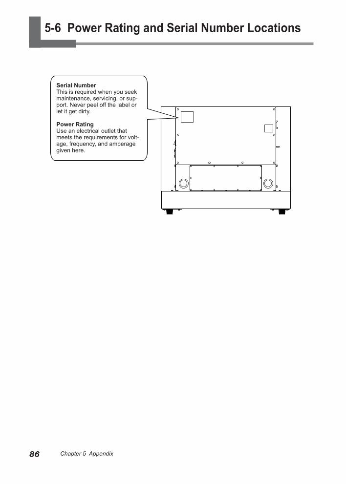
86 Chapter 5 Appendix Chapter 5 Appendix
5-6 Power Rating and Serial Number Locations
Serial NumberThis is required when you seek maintenance, servicing, or sup-port. Never peel off the label or let it get dirty.
Power RatingUse an electrical outlet that meets the requirements for volt-age, frequency, and amperage given here.
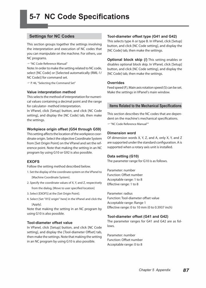
87Chapter 5 Appendix Chapter 5 Appendix
5-7 NC Code Specifications
Settings for NC Codes
This section groups together the settings involving the interpretation and execution of NC codes that you can manipulate on the machine. For others, use NC programs.
“NC Code Reference Manual"Note: In order to make the setting related to NC code, select [NC Code] or [Selected automatically (RML-1/NC Code)] for command set.
P. 46, "Selecting the Command Set"
Value interpretation methodThis selects the method of interpretation for numeri-cal values containing a decimal point and the range for calculator- method interpretation.In VPanel, click [Setup] button, and click [NC Code setting], and display the [NC Code] tab, then make the settings.
Workpiece origin offset (G54 through G59)This setting affects the location of the workpiece coor-dinate origin. Select the objective Coordinate System from [Set Origin Point] on the VPanel and set the ref-erence point. Note that making the setting in an NC program by using G10 or G92 is also possible.
EXOFSFollow the setting method described below.
1. Set the display of the coordinate system on the VPanel to
[Machine Coordinate System].
2. Specify the coordinate values of X, Y, and Z, respectively
from the dialog, [Move to user specified location]
3. Select [EXOFS] at the [Set Origin Point].
4. Select [Set "XYZ origin" here] in the VPanel and click the
[Apply].Note that making the setting in an NC program by using G10 is also possible.
Tool-diameter offset valueIn VPanel, click [Setup] button, and click [NC Code setting], and display the [Tool-diameter Offset] tab, then make the settings. Note that making the setting in an NC program by using G10 is also possible.
Tool-diameter offset type (G41 and G42)This selects type A or type B. In VPanel, click [Setup] button, and click [NC Code setting], and display the [NC Code] tab, then make the settings.
Optional block skip (/) This setting enables or disables optional block skip. In VPanel, click [Setup] button, and click [NC Code setting], and display the [NC Code] tab, then make the settings.
OverridesFeed speed (F), Main axis rotation speed (S) can be set. Make the settings in VPanel's main window.
Items Related to the Mechanical Specifications
This section describes the NC codes that are depen-dent on the machine's mechanical specifications.
“NC Code Reference Manual"”
Dimension wordOf dimension words X, Y, Z, and A, only X, Y, and Z are supported under the standard configuration. A is supported when a rotary axis unit is installed.
Data setting (G10)The parameter range for G10 is as follows.
Parameter: numberFunction: Offset numberAcceptable range: 1 to 8Effective range: 1 to 8
Parameter: radiusFunction: Tool-diameter offset valueAcceptable range: Range 1Effective range: 0 to 10 mm (0 to 0.3937 inch)
Tool-diameter offset (G41 and G42)The parameter ranges for G41 and G42 are as fol-lows.
Parameter: numberFunction: Offset numberAcceptable range: 0 to 8
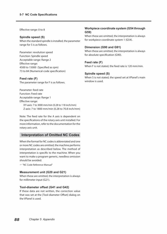
5-7 NC Code Specifications
88 Chapter 5 Appendix Chapter 5 Appendix
Effective range: 0 to 8
Spindle speed (S)When the standard spindle is installed, the parameter range for S is as follows.
Parameter: revolution speedFunction: Spindle speedAcceptable range: Range 2Effective range: 4500 to 15000 (Specified as rpm)73 to 84 (Numerical-code specification)
Feed rate (F)The parameter range for F is as follows.
Parameter: feed rateFunction: Feed rateAcceptable range: Range 1Effective range: XY-axis: 7 to 3000 mm/min (0.28 to 118 inch/mm) Z-axis: 7 to 1800 mm/min (0.28 to 70.8 inch/mm)
Note: The feed rate for the A axis is dependent on the specifications of the rotary axis unit installed. For more information, refer to the documentation for the rotary axis unit.
Interpretation of Omitted NC Codes
When the format for NC codes is abbreviated and one or more NC codes are omitted, the machine performs interpretation as described below. The method of interpretation is specific to the machine. When you want to make a program generic, needless omission should be avoided.
"NC Code Reference Manual"
Measurement unit (G20 and G21)When these are omitted, the interpretation is always for millimeter input (G21).
Tool-diameter offset (G41 and G42)If these data are not written, the correction value that was set at the [Tool-diameter Offset] dialog on the VPanel is used.
Workpiece coordinate system (G54 through G59)When these are omitted, the interpretation is always for workpiece coordinate system 1 (G54).
Dimension (G90 and G91)When these are omitted, the interpretation is always for absolute specification (G90).
Feed rate (F)When F is not stated, the feed rate is 120 mm/min.
Spindle speed (S)When S is not stated, the speed set at VPanel's main window is used.
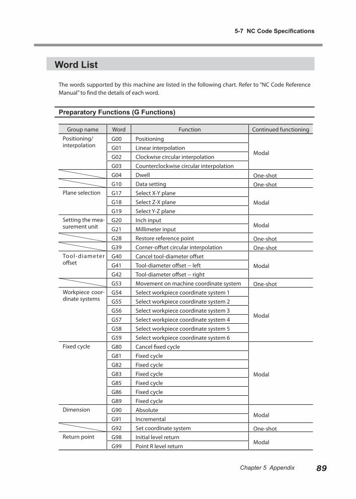
Chapter 5 Appendix
5-7 NC Code Specifications
89Chapter 5 Appendix
Word List
The words supported by this machine are listed in the following chart. Refer to “NC Code Reference Manual” to find the details of each word.
Preparatory Functions (G Functions)
Group name Word Function Continued functioningPositioning/interpolation
G00 Positioning
ModalG01 Linear interpolationG02 Clockwise circular interpolationG03 Counterclockwise circular interpolationG04 Dwell One-shotG10 Data setting One-shot
Plane selection G17 Select X-Y plane
ModalG18 Select Z-X planeG19 Select Y-Z plane
Setting the mea-surement unit
G20 Inch inputModal
G21 Millimeter inputG28 Restore reference point One-shotG39 Corner-offset circular interpolation One-shot
Tool- diameter offset
G40 Cancel tool-diameter offset
ModalG41 Tool-diameter offset -- leftG42 Tool-diameter offset -- rightG53 Movement on machine coordinate system One-shot
Workpiece coor-dinate systems
G54 Select workpiece coordinate system 1
Modal
G55 Select workpiece coordinate system 2G56 Select workpiece coordinate system 3G57 Select workpiece coordinate system 4G58 Select workpiece coordinate system 5G59 Select workpiece coordinate system 6
Fixed cycle G80 Cancel fixed cycle
Modal
G81 Fixed cycleG82 Fixed cycleG83 Fixed cycleG85 Fixed cycleG86 Fixed cycleG89 Fixed cycle
Dimension G90 AbsoluteModal
G91 IncrementalG92 Set coordinate system One-shot
Return point G98 Initial level returnModal
G99 Point R level return
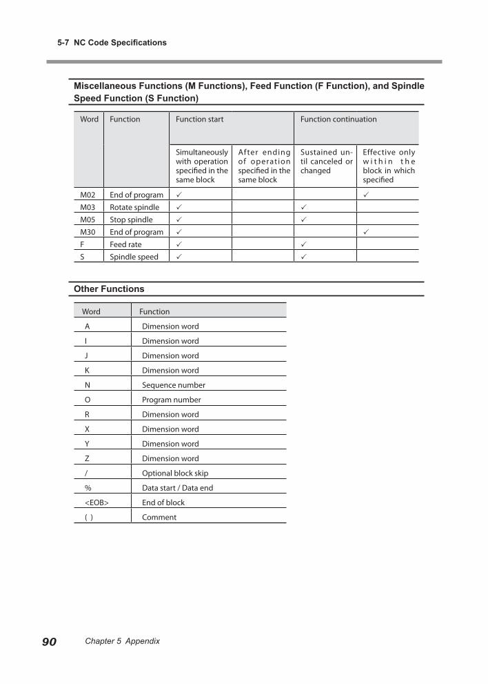
Chapter 5 Appendix
5-7 NC Code Specifications
90 Chapter 5 Appendix Chapter 5 Appendix
Miscellaneous Functions (M Functions), Feed Function (F Function), and Spindle Speed Function (S Function)
Word Function Function start Function continuation
Simultaneously with operation specified in the same block
After ending of operation specified in the same block
Sustained un-til canceled or changed
Effective only w i t h i n t h e block in which specified
M02 End of program
M03 Rotate spindle
M05 Stop spindle
M30 End of program
F Feed rate
S Spindle speed
Other Functions
Word Function
A Dimension word
I Dimension word
J Dimension word
K Dimension word
N Sequence number
O Program number
R Dimension word
X Dimension word
Y Dimension word
Z Dimension word
/ Optional block skip
% Data start / Data end
<EOB> End of block
( ) Comment
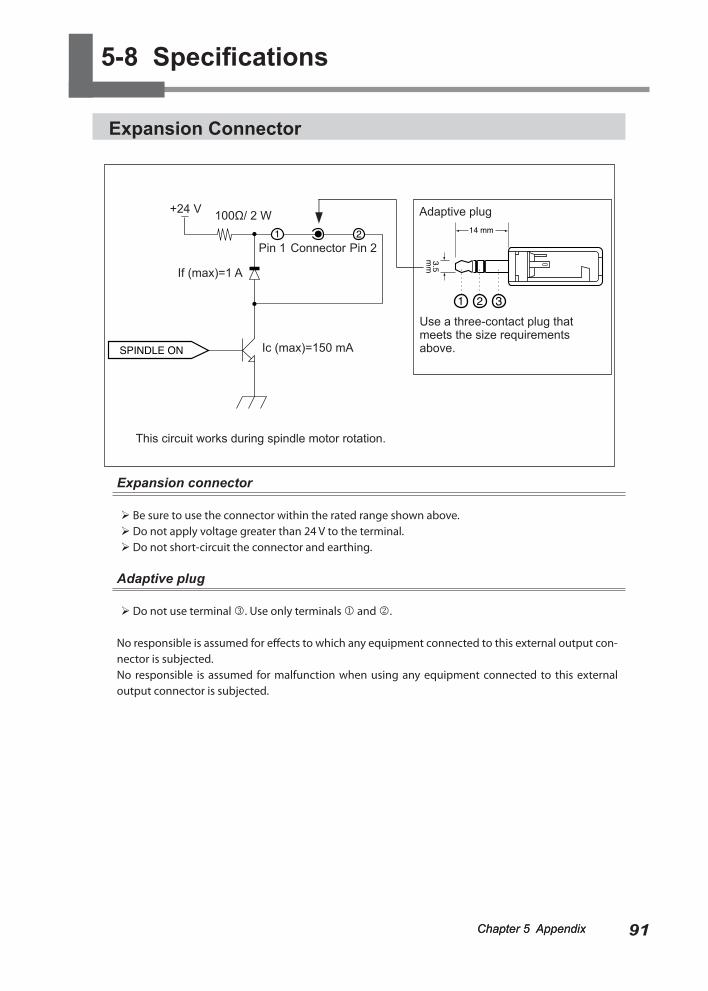
91Chapter 5 AppendixChapter 5 Appendix Chapter 5 Appendix
Expansion Connector
Expansion connector
Be sure to use the connector within the rated range shown above. Do not apply voltage greater than 24 V to the terminal. Do not short-circuit the connector and earthing.
Adaptive plug
Do not use terminal . Use only terminals and .
No responsible is assumed for effects to which any equipment connected to this external output con-nector is subjected.No responsible is assumed for malfunction when using any equipment connected to this external output connector is subjected.
Use a three-contact plug that meets the size requirements above.
This circuit works during spindle motor rotation.
Pin 1 Connector Pin 2
Ic (max)=150 mA
If (max)=1 A
Adaptive plug+24 V 100Ω/ 2 W
5-8 Specifications
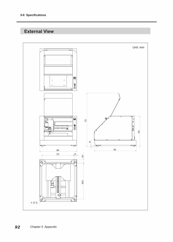
5-8 Specifications
92 Chapter 5 Appendix Chapter 5 Appendix
External View
669 760
25
971
554
579 45
63.7
654.3
4- Ø 32
Unit: mm
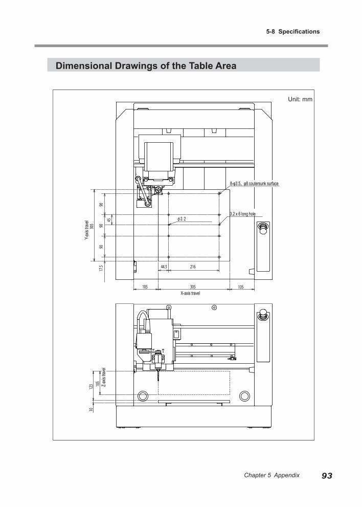
Chapter 5 Appendix
5-8 Specifications
93Chapter 5 Appendix
Dimensional Drawings of the Table Area
105 305
216 44.5
9090
9017
.5
105
305
105
Y-axis
trave
l
X-axis travel
123
10
45 φ3.2
8-φ3.5、φ8 coutersunk surface
3.2 x 6 long hole
Z-axis
trave
lUnit: mm
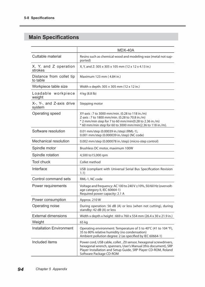
5-8 Specifications
94 Chapter 5 Appendix Chapter 5 Appendix
Main Specifications
MDX-40ACuttable material Resins such as chemical wood and modeling wax (metal not sup-
ported)
X, Y, and Z operation strokes
X, Y, and Z: 305 x 305 x 105 mm (12 x 12 x 4.13 in.)
Distance from collet tip to table
Maximum 123 mm ( 4.84 in.)
Workpiece table size Width x depth: 305 × 305 mm (12 x 12 in.)
Loadable workp iece weight
4 kg (8.8 lb)
X-, Y-, and Z-axis drive system
Stepping motor
Operating speed XY-axis : 7 to 3000 mm/min. (0.28 to 118 in./m)Z-axis : 7 to 1800 mm/min. (0.28 to 70.8 in./m)* 2 mm/min step for 7 to 60 mm/min(0.28 to 2.36 in./m)* 60 mm/min step for 60 to 3000 mm/min(2.36 to 118 in./m).
Software resolution 0.01 mm/step (0.00039 in./step) (RML-1),0.001 mm/step (0.000039 in./step) (NC code)
Mechanical resolution 0.002 mm/step (0.000078 in./step) (micro-step control)
Spindle motor Brushless DC motor, maximum 100W
Spindle rotation 4,500 to15,000 rpm
Tool chuck Collet method
Interface USB (compliant with Universal Serial Bus Specification Revision 1.1)
Control command sets RML-1, NC code
Power requirements Voltage and frequency: AC 100 to 240 V ±10%, 50/60 Hz (overvolt-age category II, IEC 60664-1)Required power capacity: 2.1 A
Power consumption Approx. 210 W
Operating noise During operation: 56 dB (A) or less (when not cutting), during standby: 42 dB (A) or less
External dimensions Width x depth x height : 669 x 760 x 554 mm (26.4 x 30 x 21.9 in.)
Weight 65 kg
Installation Environment Operating environment: Temperature of 5 to 40°C (41 to 104 °F), 35 to 80% relative humidity (no condensation)Ambient pollution degree: 2 (as specified by IEC 60664-1)
Included items Power cord, USB cable, collet , Z0 sensor, hexagonal screwdrivers, hexagonal wrench, spanners, User’s Manual (this document), SRP Player Installation and Setup Guide, SRP Player CD-ROM, Roland Software Package CD-ROM

Chapter 5 Appendix
5-8 Specifications
95Chapter 5 Appendix
System Requirements for USB Connection
Computer Model preinstalled with Windows 7, Vista (32/64-bit edition) or XP, or upgraded computer originally preinstalled with Windows XP or later.
USB cable Use the included USB cable.

产品中有毒有害物质或元素的名称及含量
部件名称
有毒有害物质或元素
铅(Pb) 汞(Hg) 镉(Cd) 六价铬
(Cr(Ⅵ))
多溴联苯
(PBB)
多溴二苯醚
(PBDE)
印刷电路板 × ○ × ○ ○ ○
头部 × ○ ○ ○ ○ ○
壳体、底架 × ○ ○ ○ ○ ○
电源 × ○ × ○ ○ ○
其他(电缆、附件等) × ○ ○ ○ ○ ○
○:表示该有毒有害物质在该部件所有均质材料中的含量均在 GB/T26572-2011 标准规定的限量要求以下。
×:表示该有毒有害物质至少在该部件的某一均质材料中的含量超出 GB/T26572-2011 标准规定的限量要求。
环保使用期限
此标志适用于在中国国内销售的电子信息产品,表示环保使用期限的年数。
所谓环保使用期限是指在自制造日起的规定期限内,产品中所含的有害物质
不致引起环境污染,不会对人身、财产造成严重的不良影响。
环保使用期限仅在遵照产品使用说明书,正确使用产品的条件下才有效。
不当的使用,将会导致有害物质泄漏的危险。
This product must be disposed of separately at your local waste recycling center. Do not dispose of in household waste bin.
Bitte führen Sie dieses Produkt separat Ihrer örtlichen Entsorgungsstelle zu. Bitte nicht mit dem normalen Hausmüll entsorgen.
Ne jetez pas le produit avec vos ordures ménagères. Portez-le dans un centre recyclage des déchets.
Questo prodotto deve essere smaltito negli appositi contenitori per la raccolta differenziata, non buttare nel cestino dei rifiuti casalinghi.
Este producto debe devolverse al centro de reciclaje más cercano a su domicilio para su correcta eliminación. No lo tire a la basura.
Deite fora separadamente este produto no seu centro de reciclagem local. Não o deite fora no seu caixote do lixo.
Lever dit product in bij een lokaal afvalverzamelpunt. NIET met normaal huishoudelijk afval afvoeren.
Dette Produkt skal smides særskilt væk på den lokale affalds- og genbrugsstation. Må ikke smides ud sammen med almindeligt husholdningsaffald.
Tätä tuotetta ei saa hävittää normaalien talousjätteiden mukana, vaan se on toimitettava ongelmajätteiden keräilypisteeseen hävitettäväksi.
Produkten måste kasseras separat på din lokala återvinningscentral. Släng inte produkten tillsammans med hushållssoporna.
Μην πετάξετε το αντικείμενο αυτό στο καλάθι των απορριμμάτων. Αφαιρέστε τις μπαταρίες και προσκομίστε το στο τοπικό κέντρο ανακύκλωσης.
For China
For EU Countries

R4-170809