Embed Size (px)
Citation preview
ME 215 – Engineering Materials I
Dr. A. Tolga Bozdanawww.gantep.edu.tr/~bozdana
Mechanical EngineeringUniversity of Gaziantep
Chapter 4
Properties in Bending and Shear (Part II)
1
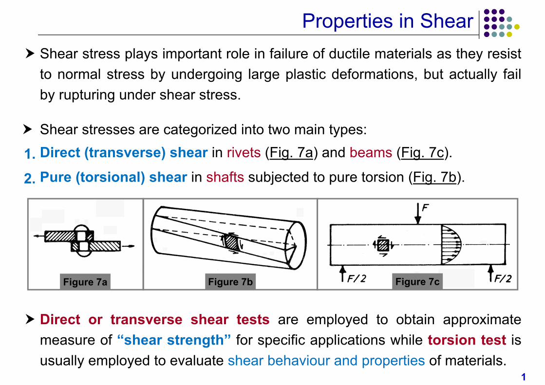
Properties in Shear Shear stress plays important role in failure of ductile materials as they resist
to normal stress by undergoing large plastic deformations, but actually failby rupturing under shear stress.
Figure 7a Figure 7cFigure 7b
Direct or transverse shear tests are employed to obtain approximatemeasure of “shear strength” for specific applications while torsion test isusually employed to evaluate shear behaviour and properties of materials.
Shear stresses are categorized into two main types:
1. Direct (transverse) shear in rivets (Fig. 7a) and beams (Fig. 7c).
2. Pure (torsional) shear in shafts subjected to pure torsion (Fig. 7b).
2
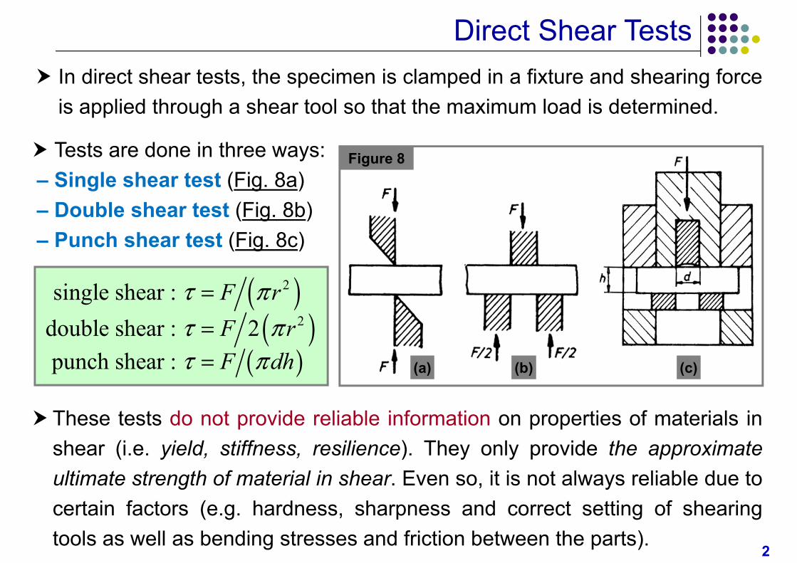
Direct Shear Tests In direct shear tests, the specimen is clamped in a fixture and shearing force
is applied through a shear tool so that the maximum load is determined.
–––
Tests are done in three ways:Single shear test (Fig. 8a)Double shear test (Fig. 8b)Punch shear test (Fig. 8c)
Figure 8
(a) (b) (c)
2
2
single shear : double shear : 2punch shear :
F rF rF dh
These tests do not provide reliable information on properties of materials inshear (i.e. yield, stiffness, resilience). They only provide the approximateultimate strength of material in shear. Even so, it is not always reliable due tocertain factors (e.g. hardness, sharpness and correct setting of shearingtools as well as bending stresses and friction between the parts).
3
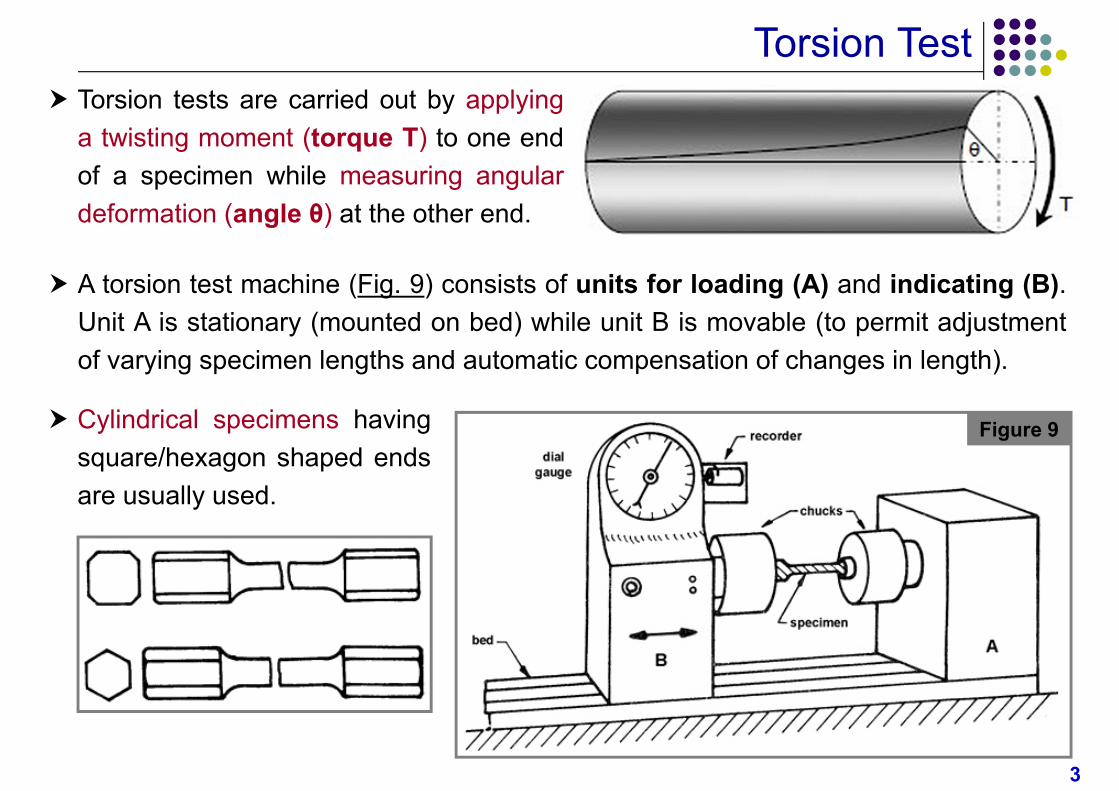
Torsion Test Torsion tests are carried out by applying
a twisting moment (torque T) to one endof a specimen while measuring angulardeformation (angle θ) at the other end.
Figure 9 Cylindrical specimens havingsquare/hexagon shaped endsare usually used.
A torsion test machine (Fig. 9) consists of units for loading (A) and indicating (B).Unit A is stationary (mounted on bed) while unit B is movable (to permit adjustmentof varying specimen lengths and automatic compensation of changes in length).
4
Torsion Test Torsion test is useful in determining the material properties such as shear
modulus of elasticity, torsional yield strength and shear modulus of rupture.Such tests can also be carried out on full-sized engineering components todetermine their behaviour under service conditions.
Torsion test offers certain advantages over tensile test:
During torsion test, no necking occurs. Therefore, the torque increases upto the moment of failure.
Plastic deformation is almost uniform over entire length of specimen,which enables the determination of deformations and stresses reliably forhighly ductile materials (especially pure metals).
Brittle or low ductility materials, that are often difficult to test in tension,can undergo quite measurable deformation in torsion test, which enablesthe determination of their mechanical properties.
In addition, torsion tests can easily be conducted at high strain rates.
5
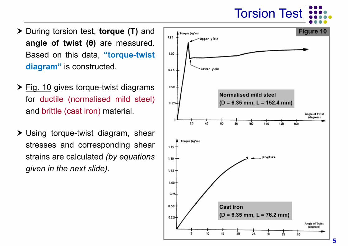
Torsion Test During torsion test, torque (T) and
angle of twist (θ) are measured.Based on this data, “torque-twistdiagram” is constructed.
Fig. 10 gives torque-twist diagramsfor ductile (normalised mild steel)and brittle (cast iron) material.
Using torque-twist diagram, shearstresses and corresponding shearstrains are calculated (by equationsgiven in the next slide).
Figure 10
Normalised mild steel(D = 6.35 mm, L = 152.4 mm)
Cast iron(D = 6.35 mm, L = 76.2 mm)
6
Shear Stress & Shear Strain
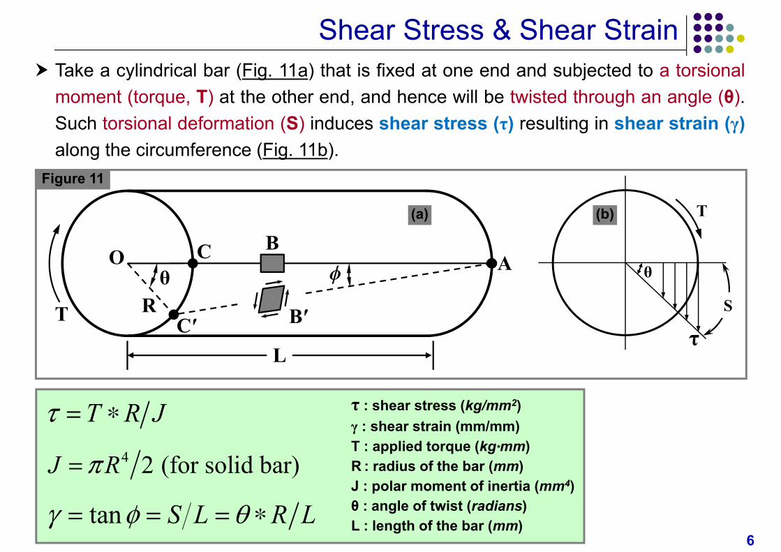
τ : shear stress (kg/mm2)γ : shear strain (mm/mm)T : applied torque (kg*mm)R : radius of the bar (mm)J : polar moment of inertia (mm4)θ : angle of twist (radians)L : length of the bar (mm)
T R J 4 2 (for solid bar)J R
tan S L R L
Take a cylindrical bar (Fig. 11a) that is fixed at one end and subjected to a torsionalmoment (torque, T) at the other end, and hence will be twisted through an angle (θ).Such torsional deformation (S) induces shear stress (τ) resulting in shear strain (γ)along the circumference (Fig. 11b).
Figure 11
T
θ ϕR
O AB
Bʹ
C
CʹL
T
θ
S
τ
(a) (b)
7
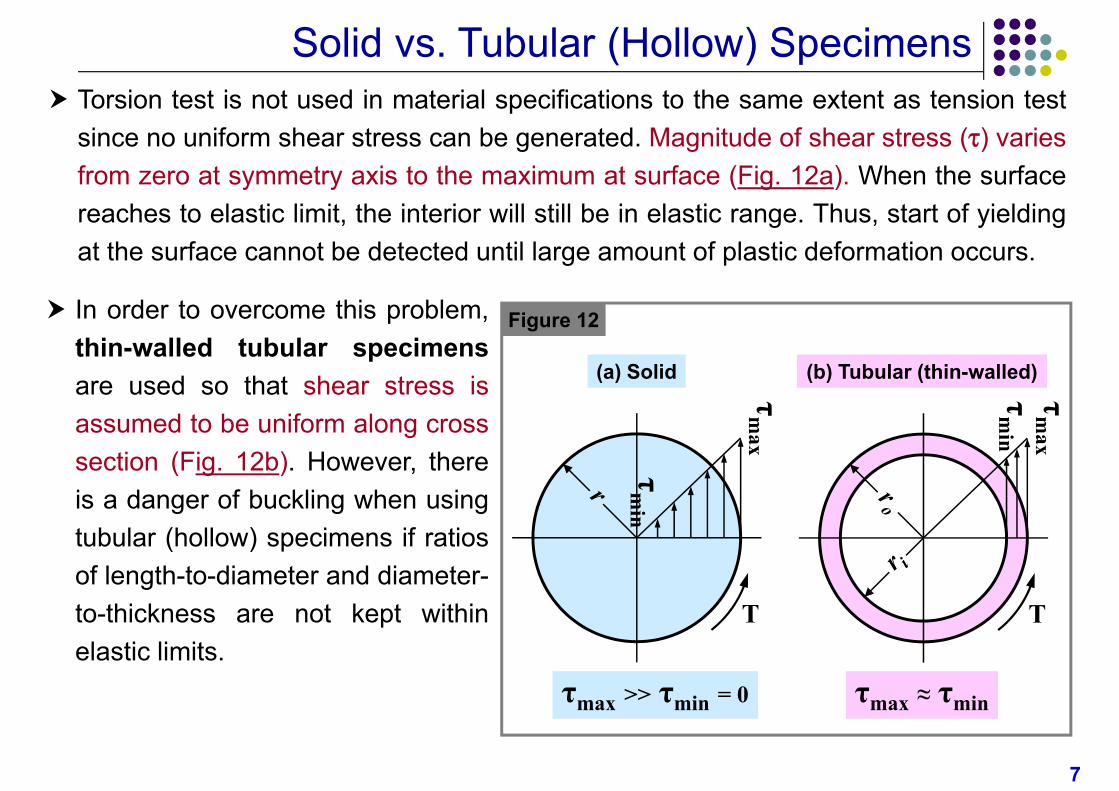
Solid vs. Tubular (Hollow) Specimens Torsion test is not used in material specifications to the same extent as tension test
since no uniform shear stress can be generated. Magnitude of shear stress () variesfrom zero at symmetry axis to the maximum at surface (Fig. 12a). When the surfacereaches to elastic limit, the interior will still be in elastic range. Thus, start of yieldingat the surface cannot be detected until large amount of plastic deformation occurs.
In order to overcome this problem,thin-walled tubular specimensare used so that shear stress isassumed to be uniform along crosssection (Fig. 12b). However, thereis a danger of buckling when usingtubular (hollow) specimens if ratiosof length-to-diameter and diameter-to-thickness are not kept withinelastic limits.
Figure 12
(b) Tubular (thin-walled)
τm
ax
T
τm
in
τmax ≈ τmin
τm
ax
T
(a) Solid
τm
in
τmax >> τmin = 0
8
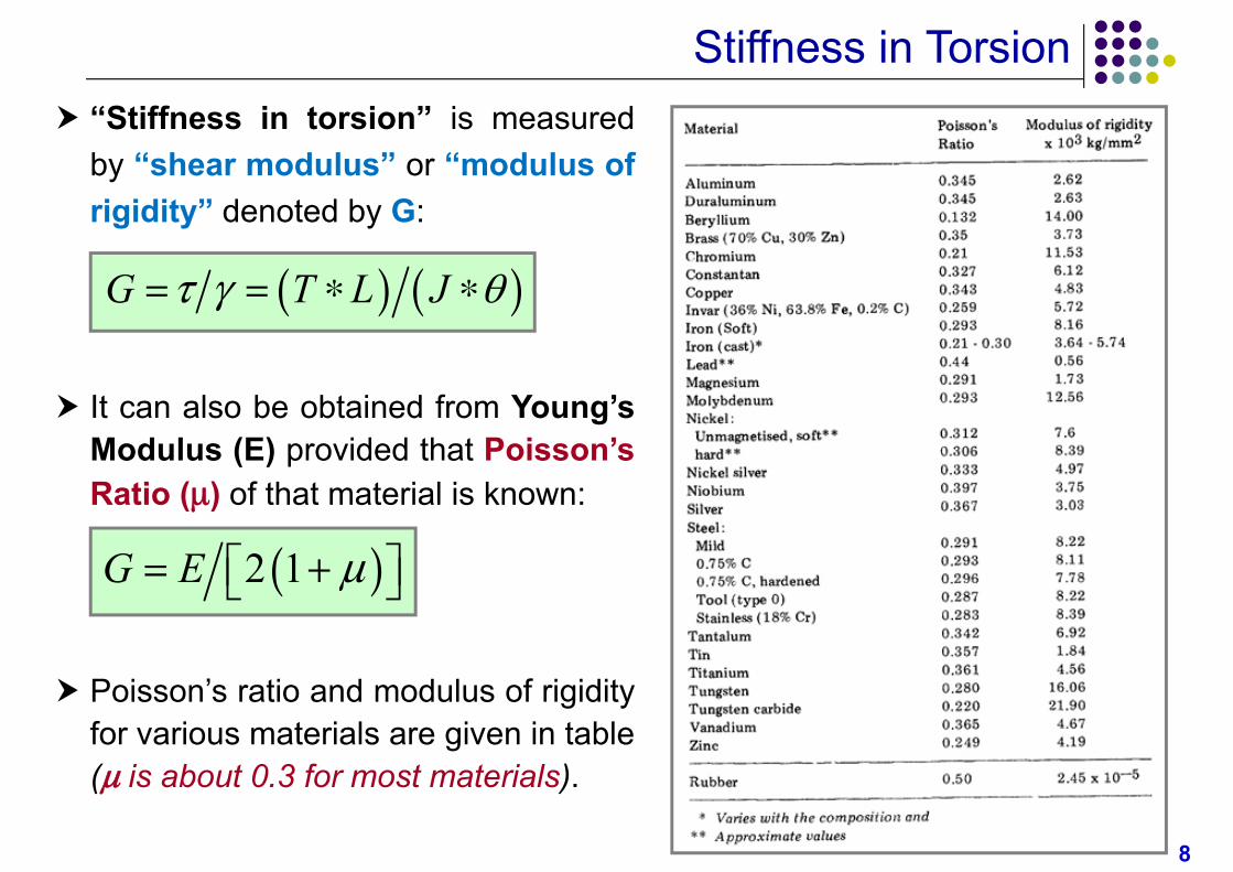
Stiffness in Torsion “Stiffness in torsion” is measured
by “shear modulus” or “modulus ofrigidity” denoted by G:
It can also be obtained from Young’sModulus (E) provided that Poisson’sRatio () of that material is known:
Poisson’s ratio and modulus of rigidityfor various materials are given in table( is about 0.3 for most materials).
G T L J
2 1G E
9
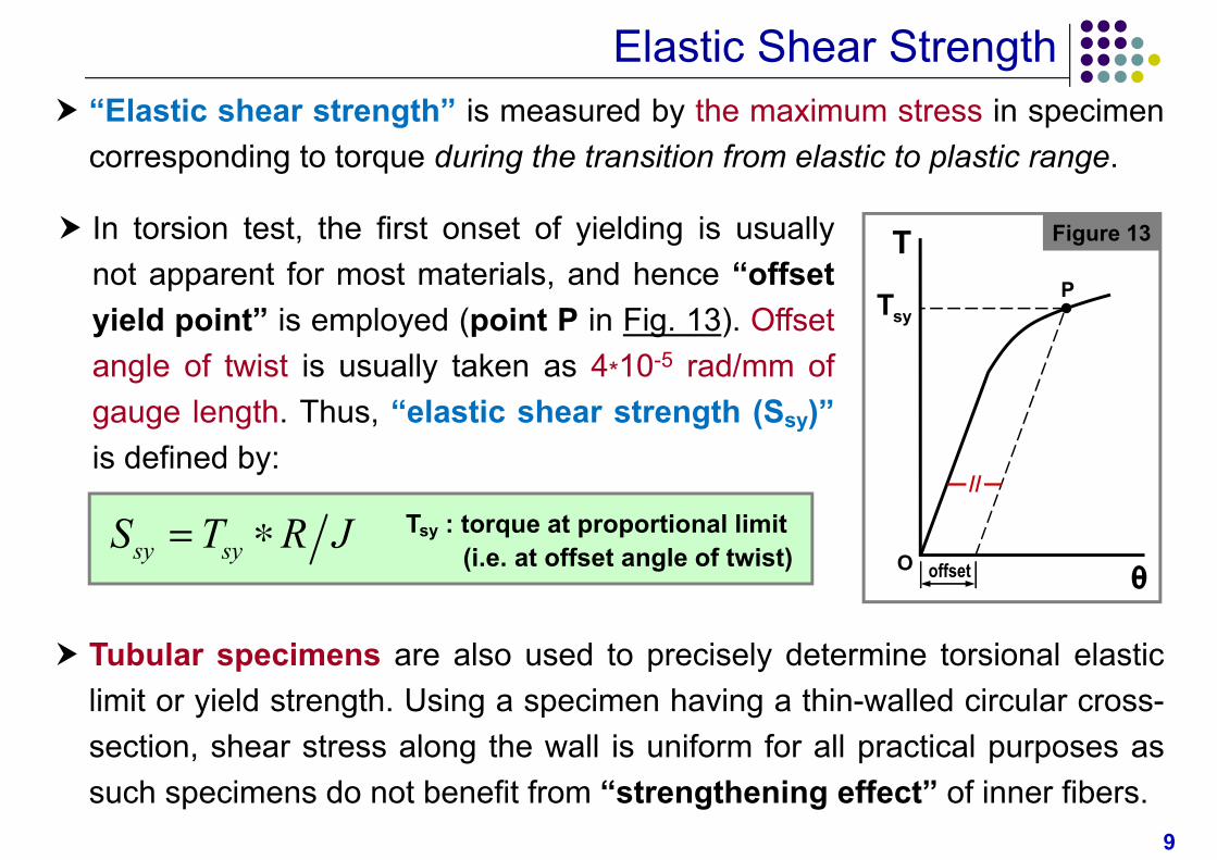
Elastic Shear Strength “Elastic shear strength” is measured by the maximum stress in specimen
corresponding to torque during the transition from elastic to plastic range.
In torsion test, the first onset of yielding is usuallynot apparent for most materials, and hence “offsetyield point” is employed (point P in Fig. 13). Offsetangle of twist is usually taken as 4*10-5 rad/mm ofgauge length. Thus, “elastic shear strength (Ssy)”is defined by:
Tubular specimens are also used to precisely determine torsional elasticlimit or yield strength. Using a specimen having a thin-walled circular cross-section, shear stress along the wall is uniform for all practical purposes assuch specimens do not benefit from “strengthening effect” of inner fibers.
Figure 13
θ
T
syT P
offsetO
//
Tsy : torque at proportional limit(i.e. at offset angle of twist)sy syS T R J
10
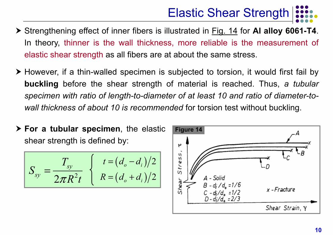
Elastic Shear Strength Strengthening effect of inner fibers is illustrated in Fig. 14 for Al alloy 6061-T4.
In theory, thinner is the wall thickness, more reliable is the measurement ofelastic shear strength as all fibers are at about the same stress.
However, if a thin-walled specimen is subjected to torsion, it would first fail bybuckling before the shear strength of material is reached. Thus, a tubularspecimen with ratio of length-to-diameter of at least 10 and ratio of diameter-to-wall thickness of about 10 is recommended for torsion test without buckling.
Figure 14 For a tubular specimen, the elasticshear strength is defined by:
22sy
sy
TS
R t
2
2o i
o i
t d d
R d d
11
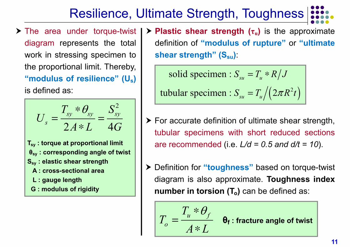
Resilience, Ultimate Strength, Toughness The area under torque-twist
diagram represents the totalwork in stressing specimen tothe proportional limit. Thereby,“modulus of resilience” (Us)is defined as:
Tsy : torque at proportional limitθsy : corresponding angle of twistSsy : elastic shear strength
A : cross-sectional areaL : gauge lengthG : modulus of rigidity
2
2 4sy sy sy
s
T SU
A L G
Plastic shear strength (τu) is the approximatedefinition of “modulus of rupture” or “ultimateshear strength” (Ssu):
2
solid specimen :
tubular specimen : 2
su u
su u
S T R J
S T R t
For accurate definition of ultimate shear strength,tubular specimens with short reduced sectionsare recommended (i.e. L/d = 0.5 and d/t = 10).
Definition for “toughness” based on torque-twistdiagram is also approximate. Toughness indexnumber in torsion (To) can be defined as:
θf : fracture angle of twistu f
o
TT
A L
12
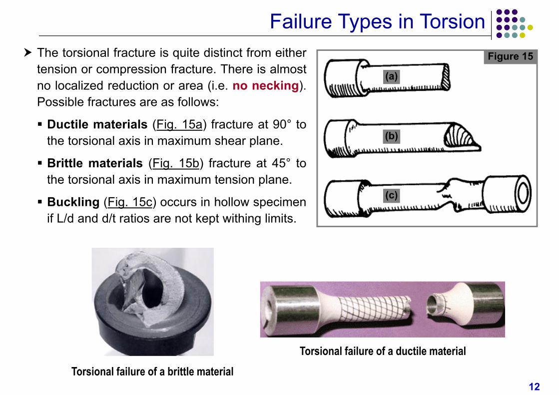
Failure Types in Torsion The torsional fracture is quite distinct from either
tension or compression fracture. There is almostno localized reduction or area (i.e. no necking).Possible fractures are as follows:
Ductile materials (Fig. 15a) fracture at 90° tothe torsional axis in maximum shear plane.
Brittle materials (Fig. 15b) fracture at 45° tothe torsional axis in maximum tension plane.
Buckling (Fig. 15c) occurs in hollow specimenif L/d and d/t ratios are not kept withing limits.
Figure 15
(a)
(b)
(c)
Torsional failure of a ductile materialTorsional failure of a brittle material

13
Failure Examples in Torsion