Embed Size (px)
DESCRIPTION
ME 234/2 HV noise investigation. N.Bondar CMU. 12/18/02. AFEB Counting Noise Test Results. Fact 1 . A few times FAST site Test 11 was failed (AFEB counting noise). AFEB threshold set to 20 fC, HV off, ALCT at self-trigger mode, noise calculated with a free running scaler. - PowerPoint PPT Presentation
Citation preview

1
ME 234/2HV noise investigation
N.Bondar
CMU.
12/18/02
2
AFEB Counting Noise Test Results
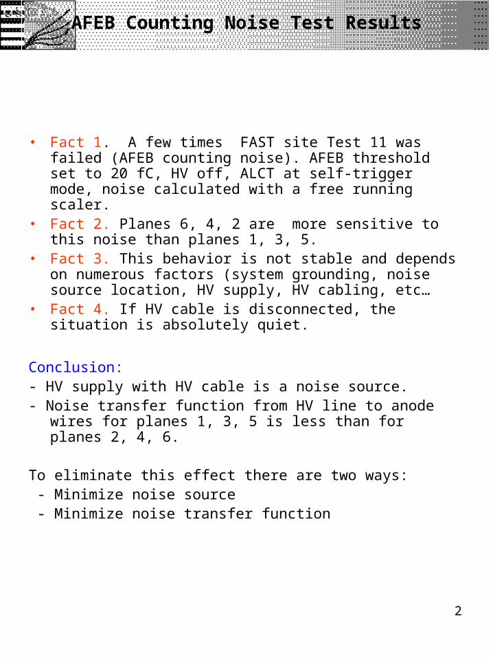
• Fact 1. A few times FAST site Test 11 was failed (AFEB counting noise). AFEB threshold set to 20 fC, HV off, ALCT at self-trigger mode, noise calculated with a free running scaler.
• Fact 2. Planes 6, 4, 2 are more sensitive to this noise than planes 1, 3, 5.
• Fact 3. This behavior is not stable and depends on numerous factors (system grounding, noise source location, HV supply, HV cabling, etc…
• Fact 4. If HV cable is disconnected, the situation is absolutely quiet.
Conclusion: - HV supply with HV cable is a noise source.- Noise transfer function from HV line to anode wires for
planes 1, 3, 5 is less than for planes 2, 4, 6.
To eliminate this effect there are two ways: - Minimize noise source - Minimize noise transfer function
3
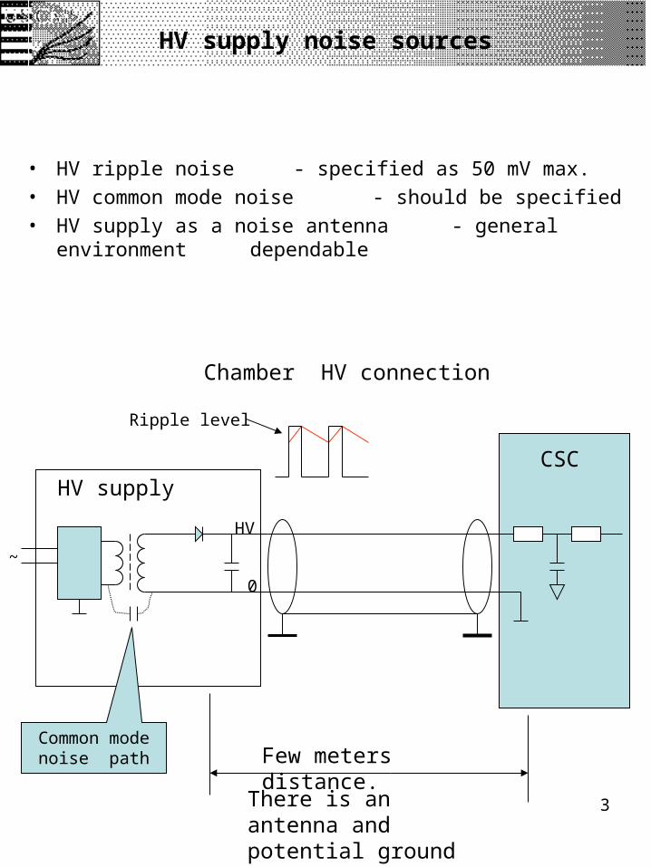
HV supply noise sources
• HV ripple noise - specified as 50 mV max.
• HV common mode noise - should be specified
• HV supply as a noise antenna - general environment dependable
~
HV
0
HV supplyCSC
Chamber HV connection
Common mode noise path
Ripple level
There is an antenna and potential ground loop
Few meters distance.

4
HV to anode wire noise path
Z
R1, 5M R2.1, 1M
R2…, 1M
Cf, 1nFCpar.
Proposed solution:Short Z with few jumpers along HV side of the chamber.Number and exact location for each jumper should be determined by test. Shorted transmission line.
Z – input impedance for the shorted line
NP
NP – equivalent noise pulse generator.
HV cable

5
-50
-40
-30
-20
-10
0
10
20
30
40
50
0 200 400 600 800 1000 1200 1400
Time, ns
Ou
tpu
t a
mp
litu
de
, mV
No jumpers
With jumpers
Jumper effect
0.5 1.0 1.5 2.0 2.5 V
Pul
se c
ount
s
O.5V 1.9V
(no jumpers) (18 jumpers)
ALCT trigger rate vs noise pulse amplitude.
A BO.3V
100%
O.1V
Placing ground jumpers on the ME23/2 chamber decreases the effect of HV parasitic pulses to the anode amplifiers by a factor of 4 (at least).
1.5V
1. ALCT trigger rate
2. AFEB test channel
6
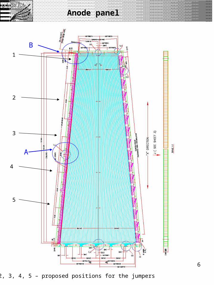
Anode panel
A
B1
2
3
4
5
1, 2, 3, 4, 5 – proposed positions for the jumpers

7
Ground wires run along chamberWidth .18” and .37”
Anode panel. HV ground path critical places
Enlarge A
Enlarge B
No copper area

8
Proposed solution for HV ground improvement
Anode panel
Bottom panelSignal ground
HV ground network
Proposed ground jumpers
External ground
Wide side Narrow side
First approximation of the jumpers location
HV side of the chamber
Picture is not to scale
Soldering joint

9
Chamber preparation for jumper installation
The chamber gap cleaning clip
A~0.25”
Abrasive sponge sticks out of the clipfor ~0.25” to prevent any damage of the chamber sealing
Cleaning procedure
Tin the chamber panel edges before jumper installation

10
Jumper preparation
Copper foil band
Jumper forming tool
Jumper bending
Jumper in place
Solder connection
Tinned edges
Tinned side out
~20mm

11
Conclusion
Proposed jumpers for HV line is a simple and reliable solution to minimize anode wire sensitivity to HV noise.
Placing ground jumpers on the ME23/2 chamber decreases the effect of HV parasitic pulses to the anode amplifiers by a factor of 4.
This solution will minimize effort and save time hunting for noise sources on the iron disk.


![SD servicio nombres docu examen2 - UPM · 2019. 4. 9. · d urrw vhuyhuv qhw =rqd d qlf hv =rqd hv hlqvwhlq ffxsp xsp hv =rqd xsp hv ]dsh il xsp hv =rqd il xsp hv qv jqx ruj =rqd](https://img.pdfslide.net/doc/110x75/613bce56f8f21c0c826934b2/sd-servicio-nombres-docu-examen2-upm-2019-4-9-d-urrw-vhuyhuv-qhw-rqd-d-qlf.jpg)


![Pool - stetten.com.br · 3 234-05 Yankauer 234-06 Yankauer Pool 234-01 234-02 234-03 234-04 229-07 229-08 230-24 Universal 230-25 230-26 Pierce 3LXV /DQJ 0HGL]LQWHFKQLN *PE+ 0DGH](https://img.pdfslide.net/doc/110x75/5fb63cd83b5e3f1b5525f393/pool-3-234-05-yankauer-234-06-yankauer-pool-234-01-234-02-234-03-234-04-229-07.jpg)