Embed Size (px)
DESCRIPTION
system okuma
Citation preview

GAUGING SYSTEMSOSP-E100M / OSP-E10M
INSTRUCTION MANUAL(8th Edition)Pub No. 4297-E-R6 (ME51-221-R8) Aug. 2004

4297-E P-(i)SAFETY PRECAUTIONS
SAFETY PRECAUTIONSEeoemr5pl001The machine is equipped with safety devices which serve to protect personnel and the machine
itself from hazards arising from unforeseen accidents. However, operators must not rely exclusivelyon these safety devices: they must also become fully familiar with the safety guidelines presentedbelow to ensure accident-free operation.This instruction manual and the warning signs attached to the machine cover only those hazardswhich Okuma can predict. Be aware that they do not cover all possible hazards.
1. Precautions Relating to Machine InstallationEeoemr5pl002(1) Install the machine at a site where the following conditions (the conditions for achievement of
the guaranteed accuracy) apply.
• Ambient temperature: 17 to 25°C
• Ambient humidity: 40% to 75% at 20°C (no condensation)
• Site not subject to direct sunlight or excessive vibration; environment as free of dust, acid,corrosive gases, and salt spray as possible.
(2) Prepare a primary power supply that complies with the following requirements.
• Voltage: 200 V
• Voltage fluctuation: ±10% max.
• Power supply frequency: 50/60 Hz
• Do not draw the primary power supply from a distribution panel that also supplies a majornoise source (for example, an electric welder or electric discharge machine) since this couldcause malfunction of the CNC unit.
• If possible, connect the machine to a ground not used by any other equipment. If there is nochoice but to use a common ground, the other equipment must not generate a large amountof noise (such as an electric welder or electric discharge machine).
(3) Installation EnvironmentObserve the following points when installing the control enclosure.
• Make sure that the CNC unit will not be subject to direct sunlight.
• Make sure that the control enclosure will not be splashed with chips, water, or oil.
• Make sure that the control enclosure and operation panel are not subject to excessive vibra-tions or shock.
• The permissible ambient temperature range for the control enclosure is 0 to 40°C.
• The permissible ambient humidity range for the control enclosure is 30 to 95% (no conden-sation).
• The maximum altitude at which the control enclosure can be used is 1000 m (3281ft.).
2. Points to Check before Turning on the PowerEeoemr5pl003(1) Close all the doors of the control enclosure and operation panel to prevent the entry of water,
chips, and dust.
(2) Make absolutely sure that there is nobody near the moving parts of the machine, and that thereare no obstacles around the machine, before starting machine operation.
(3) When turning on the power, turn on the main power disconnect switch first, then the CONTROLON switch on the operation panel.

4297-E P-(ii)SAFETY PRECAUTIONS
3. Precautions Relating to OperationEeoemr5pl004(1) After turning on the power, carry out inspection and adjustment in accordance with the daily
inspection procedure described in this instruction manual.
(2) Use tools whose dimensions and type are appropriate for the work undertaken and the machinespecifications. Do not use badly worn tools since they can cause accidents.
(3) Do not, for any reason, touch the spindle or tool while spindle indexing is in progress since thespindle could rotate: this is dangerous.
(4) Check that the workpiece and tool are properly secured.
(5) Never touch a workpiece or tool while it is rotating: this is extremely dangerous.
(6) Do not remove chips by hand while machining is in progress since this is dangerous. Alwaysstop the machine first, then remove the chips with a brush or broom.
(7) Do not operate the machine with any of the safety devices removed. Do not operate themachine with any of the covers removed unless it is necessary to do so.
(8) Always stop the machine before mounting or removing a tool.
(9) Do not approach or touch any moving part of the machine while it is operating.
(10) Do not touch any switch or button with wet hands. This is extremely dangerous.
(11) Before using any switch or button on the operation panel, check that it is the one intended.
4. Precautions Relating to the ATCEeoemr5pl010(1) The tool clamps of the magazine, spindle, etc., are designed for reliability, but it is possible that
a tool could be released and fall in the event of an unforeseen accident, exposing you to danger:do not touch or approach the ATC mechanism during ATC operation.
(2) Always inspect and change tools in the magazine in the manual magazine interrupt mode.
(3) Remove chips adhering to the magazine at appropriate intervals since they can cause misoper-ation. Do not use compressed air to remove these chips since it will only push the chips furtherin.
(4) If the ATC stops during operation for some reason and it has to be inspected without turning thepower off, do not touch the ATC since it may start moving suddenly.
5. On Finishing WorkEeoemr5pl005(1) On finishing work, clean the vicinity of the machine.
(2) Return the ATC, APC and other equipment to the predetermined retraction position.
(3) Always turn off the power to the machine before leaving it.
(4) To turn off the power, turn off the CONTROL ON switch on the operation panel first, then themain power disconnect switch.

4297-E P-(iii)SAFETY PRECAUTIONS
6. Precautions during Maintenance Inspection and When Trouble Occurs
Eeoemr5pl006In order to prevent unforeseen accidents, damage to the machine, etc., it is essential to observe thefollowing points when performing maintenance inspections or during checking when trouble hasoccurred.
(1) When trouble occurs, press the emergency stop button on the operation panel to stop themachine.
(2) Consult the person responsible for maintenance to determine what corrective measures need tobe taken.
(3) If two or more persons must work together, establish signals so that they can communicate toconfirm safety before proceeding to each new step.
(4) Use only the specified replacement parts and fuses.
(5) Always turn the power off before starting inspection or changing parts.
(6) When parts are removed during inspection or repair work, always replace them as they wereand secure them properly with their screws, etc.
(7) When carrying out inspections in which measuring instruments are used - for example voltagechecks - make sure the instrument is properly calibrated.
(8) Do not keep combustible materials or metals inside the control enclosure or terminal box.
(9) Check that cables and wires are free of damage: damaged cables and wires will cause currentleakage and electric shocks.
(10) Maintenance inside the Control Enclosure
a) Switch the main power disconnect switch OFF before opening the control enclosure door.
b) Even when the main power disconnect switch is OFF, there may some residual charge in theMCS drive unit (servo/spindle), and for this reason only service personnel are permitted toperform any work on this unit. Even then, they must observe the following precautions.
• MCS drive unit (servo/spindle)The residual voltage discharges two minutes after the main switch is turned OFF.
c) The control enclosure contains the NC unit, and the NC unit has a printed circuit boardwhose memory stores the machining programs, parameters, etc. In order to ensure that thecontents of this memory will be retained even when the power is switched off, the memory issupplied with power by a battery. Depending on how the printed circuit boards are handled,the contents of the memory may be destroyed and for this reason only service personnelshould handle these boards.
(11) Periodic Inspection of the Control Enclosure
a) Cleaning the cooling unitThe cooling unit in the door of the control enclosure serves to prevent excessive temperaturerise inside the control enclosure and increase the reliability of the NC unit. Inspect the follow-ing points every three months.
• Is the fan motor inside the cooling unit working?The motor is normal if there is a strong draft from the unit.
• Is the external air inlet blocked?If it is blocked, clean it with compressed air.
4297-E P-(iv)SAFETY PRECAUTIONS
7. General PrecautionsEeoemr5pl007(1) Keep the vicinity of the machine clean and tidy.
(2) Wear appropriate clothing while working, and follow the instructions of someone with sufficienttraining.
(3) Make sure that your clothes and hair cannot become entangled in the machine. Machine opera-tors must wear safety equipment such as safety shoes and goggles.
(4) Machine operators must read the instruction manual carefully and make sure of the correct pro-cedure before operating the machine.
(5) Memorize the position of the emergency stop button so that you can press it immediately at anytime and from any position.
(6) Do not access the inside of the control panel, transformer, motor, etc., since they contain high-voltage terminals and other components which are extremely dangerous.
(7) If two or more persons must work together, establish signals so that they can communicate toconfirm safety before proceeding to each new step.
8. Symbols Used in This ManualEeoemr5pl008The following warning indications are used in this manual to draw attention to information of particu-
lar importance. Read the instructions marked with these symbols carefully and follow them.
Indicates an imminent hazard which, if not avoided, will result in death or serious injury.
Indicates hazards which, if not avoided, could result in death or serious injury.
Indicates hazards which, if not avoided, could result in minor injuries or damage to devices or equipment.
Indicates precautions relating to operation or use.
DANGER
WARNING
CAUTION
NOTICE

4297-E P-(i)INTRODUCTION
INTRODUCTIONEeoemr5an001Thank you very much for choosing our CNC system. This numerical control system is a expandable
CNC with various features including a multi-main CPU system. Major features of the CNC systemare described below.
(1) Expandable CNC with a multi-main CPU system A multi-main CPU system on which up to seven engines (main CPUs) can be mounted is used.An excellent performance and cost effectiveness have been realized as a leader of increasinglyrapid and accurate machine tools. The CNC system can be adapted to any models and varia-tions by changing the construction of the main CPUs. The machine is controlled by a built-inPLC.
(2) Compact and highly reliableThe CNC system has become compact and highly reliable because of advanced hardwaretechnology, including UCMB (Universal Compact Main Board), I/O link, and servo link. The‘variable software’ as a technical philosophy of the OSPs supported by a flash memory. Func-tions may be added to the CNC system as required after delivery.
(3) NC operation panelsThe following types of NC operation panels are offered to improve the user-friendliness.
• Color CRT operation panels
• Thin color operation panels (horizontal)
• Thin color operation panels (vertical)One or more of the above types may not be used for some models.
(4) Machining management functionsThese functions contribute to the efficient operation of the CNC system and improve the profit-ability from small quantity production of multiple items and variable quantity production of varia-tions. Major control functions are described below.
a) Reduction of setup timeWith increase in small-volume production, machining data setting is more frequentlyneeded. The simplified file operation facilitates such troublesome operation. The documentsnecessary for setup, such as work instructions, are displayed on the CNC system to elimi-nate the necessity of controlling drawings and further reduce the setup time.
b) Production Status MonitorThe progress and operation status can be checked on a real-time basis on the screen of theCNC system.
c) Reduction of troubleshooting timeCorrect information is quickly available for troubleshooting.
(5) Help functionsWhen an alarm is raised, press the help key to view the content of the alarm.This helps take quick action against the alarm.
To operate the CNC system to its maximum performance, thoroughly read and understand thisinstruction manual before use.Keep this instruction manual at hand so that it will be available when you need a help.
Screens
Different screens are used for different models. Therefore, the screens used on your CNC system may differ from those shown in this manual.

4297-E P-(i) TABLE OF CONTENTS
TABLE OF CONTENTS
SECTION 1 AUTOMATIC TOOL LENGTH OFFSET/AUTOMATIC TOOL BREAKAGE DETECTION FUNCTION........................................................1
1. Overview....................................................................................................................................... 1
1-1. Displaying the Result of Gauging .......................................................................................... 2
1-2. Function Menu....................................................................................................................... 3
2. Automatic Tool Length Offset/Automatic Tool Breakage Detection Operation............................. 9
2-1. Setting the Touch Sensor Zero Point .................................................................................. 10
2-2. Setting the Tool Pot No./Tool No. Table.............................................................................. 15
2-3. Operation Mode Designation............................................................................................... 16
2-4. Automatic Tool Length Offset Function ............................................................................... 18
2-5. Setting the Tool Change Position (Other Than MC-H) ........................................................ 22
2-6. Automatic Tool Breakage Detection .................................................................................... 23
2-7. Cycle Time Reduction for Automatic Tool Length Offset/Automatic Tool Breakage Detection Cycle ................................................................................................................... 28
2-8. New Cycle Time Reduction Function for Automatic Tool Length Offset/Automatic Tool Breakage Detection Cycle ................................................................................................... 30
3. Automatic Tool Length Offset/Automatic Tool Breakage Detection Function for Special Tools and Attachments .................................................................................................. 34
3-1. Automatic Tool Length Offset/Automatic Tool Breakage Detection Function for Horizontal Tools of MCM ..................................................................................................... 34
3-2. Operation for Automatic Tool Length Offset/Automatic Tool Breakage Detection on B/C-axis Attachments, 90° Angular Attachments and Extension Attachments (Option) ..... 41
3-3. Operation of Automatic Tool Length Offset/Automatic Tool Breakage Detection with 30° Angular Attachments (Option)....................................................................................... 50
4. Y-axis Escape Position (MCM-B/MCR-B II/MCR-A/VH-40)........................................................ 62
4-1. Setting the Y-axis Escape Position...................................................................................... 62
4-2. Tool Movements during Automatic Tool Length Offset (Cutter Radius Compensation)/Automatic Tool Breakage Detection Cycle .......................................................................... 63
5. Interference Prevention Measures for MCV-A/MCV-A II During Execution of the Automatic Tool Length Offset/Automatic Tool Breakage Detection Cycle.................................. 64
5-1. Touch Sensor Operation Interlock....................................................................................... 64
5-2. Measures against Interference during Execution of the Automatic Tool Length Offset/Tool Breakage Detection Cycle ........................................................................................... 64
6. Variables Used in Subprograms ................................................................................................. 66
6-1. Table of Subprograms and Variables .................................................................................. 66
6-2. Table of Subprograms and Variables (MCM Horizontal Tools) ........................................... 69
6-3. How to Use Variables .......................................................................................................... 72
7. Cautions on Operation................................................................................................................ 80
8. Program Examples ..................................................................................................................... 82
8-1. Automatic Tool Length Offset .............................................................................................. 82
4297-E P-(ii) TABLE OF CONTENTS
8-2. Automatic Tool Breakage Detection .................................................................................... 84
9. Alarm List .................................................................................................................................... 87
SECTION 2 AUTOMATIC GAUGING FUNCTION ........................................................94
1. Overview..................................................................................................................................... 94
1-1. Dimension Check Function.................................................................................................. 94
1-2. Automatic Zero Offset Function........................................................................................... 94
2. Operation of the Automatic Gauging Function............................................................................ 95
2-1. Setting the Datum Hole Zero Point ...................................................................................... 96
2-2. Touch Probe Radius Compensation.................................................................................... 98
2-3. Touch Probe Length Offset ............................................................................................... 103
2-4. Inner Diameter (ID) Gauging Function .............................................................................. 105
2-5. Outer Diameter (OD) Gauging Function............................................................................ 107
2-6. End Face Gauging Cycle................................................................................................... 110
2-7. Saving of Gauging Cycle Results ...................................................................................... 115
2-8. Calculating the Center and Distance between Two Points................................................ 116
2-9. Calculating the Center and Distance between Two End Faces ........................................ 118
2-10.Automatic Zero Offset Function........................................................................................ 121
2-11.Copying the Touch Probe Offset Data.............................................................................. 122
3. Automatic Gauging Function for B-/C-axis, 90° Angular and Extension Attachments (Option) ............................................................................................... 123
3-1. Automatic Gauging for 90° Angular Attachment and B-/C-axis Attachment (PAB=90°)... 125
3-2. Automatic Gauging for Extension Attachment and B-/C-axis Attachment (PAB=0°)......... 126
4. Power ON/OFF Cycle of Renishaw's Optical Touch Probe (MP7/MP9/MP10) ....................... 127
4-1. Power ON/OFF Cycle Commands .................................................................................... 127
4-2. Power ON/OFF Cycle Operation ....................................................................................... 128
5. Details ....................................................................................................................................... 130
5-1. Touch Probe Movements .................................................................................................. 130
5-2. Approach Speed to the Workpiece.................................................................................... 133
5-3. Variables Used in Subprograms........................................................................................ 135
6. Touch Probe Safety Measures ................................................................................................. 147
6-1. Checking Proximity Switch Operation ............................................................................... 147
6-2. Replacing the Touch Probe Battery................................................................................... 148
7. Supplementary Information....................................................................................................... 149
8. Program Examples ................................................................................................................... 151
8-1. ID Gauging ........................................................................................................................ 151
8-2. OD Gauging....................................................................................................................... 152
8-3. End Face Gauging on Z-axis............................................................................................. 153
8-4. Distance between End Faces (X-axis direction) ................................................................ 154
8-5. Automatic Zero Offset........................................................................................................ 155

4297-E P-(iii) TABLE OF CONTENTS
8-6. Example Program for MCM Horizontal Spindle ................................................................. 156
9. Examples of Gauging Result Display ....................................................................................... 159
10.Alarm List .................................................................................................................................. 162
10-1.Alarm List.......................................................................................................................... 162
10-2.Gauging Impossible Cause Code Chart (Alarm B 2305)................................................. 164
SECTION 3 GAUGING DATA OUTPUT FUNCTION ..................................................170
1. Overview................................................................................................................................... 170
1-1. Parameters ........................................................................................................................ 170
1-2. Output Operation ............................................................................................................... 171
1-3. Example Program.............................................................................................................. 172
1-4. Example of Outputs ........................................................................................................... 173
1-5. Output Items ...................................................................................................................... 174
2. Interface Specifications for Connecting VP-600 ....................................................................... 175
2-1. Connection Diagram.......................................................................................................... 175
2-2. Parameters ........................................................................................................................ 176
SECTION 4 GAUGING DATA OUTPUT TO FILE .......................................................177
1. Outline ...................................................................................................................................... 177
2. Parameters ............................................................................................................................... 177
2-1. NC Optional Parameter Bit ................................................................................................ 177
3. Designation of Displaying Device ............................................................................................. 178
4. Print Command......................................................................................................................... 178
4-1. System Variables for Printing ............................................................................................ 179
SECTION 5 MANUAL GAUGING ................................................................................181
1. Overview................................................................................................................................... 181
1-1. Specifications .................................................................................................................... 181
1-2. Overview of Manual Gauging Functions............................................................................ 182
1-3. List of Display Screens ...................................................................................................... 186
2. Basic Operation ........................................................................................................................ 187
3. Preparation for Gauging ........................................................................................................... 188
3-1. Preparation for Work Gauging/Tool Length Gauging Cycles ............................................ 188
3-2. Preparation for Cutter Radius Compensation Cycle.......................................................... 195
4. Work Gauging........................................................................................................................... 197
4-1. End Face Gauging (X, Y, Z) .............................................................................................. 197
4-2. I.D. Center Gauging........................................................................................................... 202
4-3. O.D. Center Gauging......................................................................................................... 207
4-4. Internal Faces Center Gauging ......................................................................................... 213
4-5. External Faces Center Gauging ........................................................................................ 225

4297-E P-(iv) TABLE OF CONTENTS
4-6. Inclination and Corner Gauging......................................................................................... 237
5. Tool Length Gauging ................................................................................................................ 244
6. Cutter Radius Gauging ............................................................................................................. 247
7. Comparison and Calculation of Gauging Results ..................................................................... 250
7-1. Transferring Gauging Results............................................................................................ 250
7-2. Comparison with Gauging Data......................................................................................... 252
7-3. Example of Calculation Results Display ............................................................................ 252
8. Error List ................................................................................................................................... 255
SECTION 6 INTERACTIVE GAUGING FUNCTION....................................................257
1. Specifications............................................................................................................................ 257
2. List of Display Screen ............................................................................................................... 258
3. Switches ................................................................................................................................... 259
3-1. Main Operation Panel ........................................................................................................ 259
3-2. Interactive Gauging Operation Panel ................................................................................ 261
4. Terminology .............................................................................................................................. 262
5. Basic Operation ........................................................................................................................ 264
6. Outline of Interactive Gauging Function ................................................................................... 265
7. Work Gauging Function ............................................................................................................ 271
7-1. PARAMETER (WORK) Screen ......................................................................................... 271
7-2. PREPARATION (WORK) Screen...................................................................................... 272
7-3. X, Y, Z END FACE ............................................................................................................ 278
7-4. I.D. CENTER ..................................................................................................................... 282
7-5. O.D. CENTER ................................................................................................................... 285
7-6. INT END CENTER ............................................................................................................ 287
7-7. EXT END CENTER ........................................................................................................... 290
7-8. INCLINE, CORNER........................................................................................................... 293
8. Tool Length Gauging ................................................................................................................ 296
8-1. Parameter (Tool Length) ................................................................................................... 296
8-2. Preparation (Tool Length).................................................................................................. 297
8-3. Tool Length Gauging ......................................................................................................... 300
9. Other Supplementary Explanations .......................................................................................... 303
10.Operation Flow ......................................................................................................................... 305
11.Error List ................................................................................................................................... 306
SECTION 7 NON-CONTACT SENSOR CALCULATION FUNCTION.........................308
1. What is Non-contact Sensor? ................................................................................................... 308
2. Outline ...................................................................................................................................... 309
3. Maker's Subprogram in the Movable Sensor Mode.................................................................. 310
4. Maker's Subprogram in the Fixed Sensor Mode....................................................................... 330

4297-E P-(v) TABLE OF CONTENTS
5. Maker's Subprogram for Gauging a Vertical Spindle Tool in the Fixed Sensor Mode.............. 331
6. Maker's Subprogram for Gauging a Horizontal Spindle Tool in the Fixed Sensor Mode.......... 345
7. List of Alarms ............................................................................................................................ 359
SECTION 8 NON-CONTACT SENSOR GAUGING FUNCTION FOR HORIZONTAL MC ...................................................................................360
1. What is Non-contact Sensor? ................................................................................................... 360
2. Outline ...................................................................................................................................... 361
3. Gauging with the Fixed Sensor................................................................................................. 361
4. Each Manufacturer's Subprogram for the Fixed Sensor........................................................... 362
5. List of Alarms ............................................................................................................................ 380
SECTION 9 SPECIAL BARRIER FUNCTION FOR HORIZONTAL MC......................381
1. Outline ...................................................................................................................................... 381
2. Detailed Specifications ............................................................................................................. 381
2-1. Parameter Setting.............................................................................................................. 381
2-2. Setting Items...................................................................................................................... 382
2-3. Barrier Range Setting Example ......................................................................................... 383
2-4. Barrier Alarm and Resetting Method ................................................................................. 383
3. Alarms....................................................................................................................................... 384
3-1. Alarm A.............................................................................................................................. 384
SECTION 10NON-CONTACT SENSOR GAUGING FUNCTION FOR MCR-AF.........385
1. What is Non-contact Sensor? ................................................................................................... 385
2. Outline ...................................................................................................................................... 386
3. Manufacturer's Subprogram for the Fixed Sensor .................................................................... 387
4. Manufacturer's Subprogram for Gauging Vertical Spindle Tools with the Fixed Sensor .......... 387
5. List of Alarms ............................................................................................................................ 406
SECTION 11NON-CONTACT SENSOR GAUGING FUNCTION FOR 30°/45° AT (103 VERSIONS) .....................................................................................407
1. What is Non-contact Sensor? ................................................................................................... 407
2. Outline ...................................................................................................................................... 408
3. Manufacturer's Subprogram for the Fixed Sensor .................................................................... 409
4. Manufacturer's Subprogram for 30°/45° AT Tool Gauging by the Fixed Sensor ...................... 410
5. List of Alarms ............................................................................................................................ 428

4297-E P-1SECTION 1 AUTOMATIC TOOL LENGTH OFFSET/AUTOMATIC TOOL BREAKAGE DETECTION
SECTION 1 AUTOMATIC TOOL LENGTH OFFSET/AUTOMATIC TOOL BREAKAGE DETEC-TION FUNCTION
1. OverviewEeoemr5s1001The automatic tool length offset/automatic tool breakage detection function automatically calculates
the tool offset data and detects breakage (chipping) of tools such as drills, taps, reamers and boringbars.The specifications of this function are classified into the following two types.
• Specifications for automatic tool length offset only, and
• Specifications for automatic tool length offset and automatic tool breakage detection
A touch sensor is mounted in the machine: a tool mounted in the spindle is brought into contact withthis touch sensor to determine the tool offset data and to detect if the tool has been broken.For tools which are mounted and removed without using the ATC, refer to the section Tool Manage-ment Function in the special specifications of the Operation Manual.
(1) Automatic Tool Length OffsetWith the tool length offset function, the tool mounted in the spindle is brought into contact withthe touch sensor to calculate the tool length. A subprogram prepared for this purpose is usedfor this operation.
(2) Automatic Tool Breakage DetectionWith the automatic tool breakage detection function, the same contact detection cycle as usedfor the tool length offset function is executed to obtain the tool length.The function compares the obtained tool length with the tool length offset data stored in theCNC memory to judge if the tool has been broken.If the tool is found to have been broken, it is replaced with a spare tool.

4297-E P-2SECTION 1 AUTOMATIC TOOL LENGTH OFFSET/AUTOMATIC TOOL BREAKAGE DETECTION
1-1. Displaying the Result of GaugingEeoemr5s1004Display the screen that displays the gauging result (GAUGING RESULTS screen) by following the
steps indicated below.
Procedure :
1 Select an operation mode (automatic, MDI, manual).
2 Press function key [F8] (DISPLAY CHANGE).The DISPLAY CHANGE window opens.
3 In the DISPLAY CHANGE window, select “GAUGING RESULTS”.
4 Press function key [F8] (CLOSE).The GAUGING RESULTS screen, shown below, is displayed.
EIOEMR5S1001R01

4297-E P-3SECTION 1 AUTOMATIC TOOL LENGTH OFFSET/AUTOMATIC TOOL BREAKAGE DETECTION
1-2. Function MenuEeoemr5s1005The function menu switches as shown below to display the functions relating to the gauging result
when the extend key, to the right of function key [F8] (DISPLAY CHANGE), is pressed.
EIOEMR5S1002R01
When the extend key is pressed.
EIOEMR5S1003R01
The function menu relating to gauging result processing is described below.
For details on the function keys, refer to [1-2-1. TOOL/ZERO Function Key] to [1-2-5. VARIOUS ON/OFF Function Key].
Function Menu Description
TOOL/ZERO Displays the presently set zero offset/tool offset number.
MSB ZERO ON/OFF Displays the offset data presently set for the individual zero offset num-bers.
MSB TOOL ON/OFF Displays the offset data presently set for the tool length offset number and the cutter diameter offset number.
SENSstat ON/OFF Displays the value set for system variable VNCOM and the sensor con-tact status.
VARIOUS ON/OFF Displays the values set for the system variables.

4297-E P-4SECTION 1 AUTOMATIC TOOL LENGTH OFFSET/AUTOMATIC TOOL BREAKAGE DETECTION
1-2-1. TOOL/ZERO Function Key
Eeoemr5s1006The TOOL/ZERO pop-up window displays the presently set zero offset number and tool offset num-bers. To display the TOOL/ZERO pop-up window, follow the procedure indicated below.
Procedure :
1 Display the GAUGING RESULTS screen.For the procedure used to display the GAUGING RESULTS screen, refer to [1-1. Displaying theResult of Gauging].
2 Press the extend key to switch the function menu.
3 Press function key [F2] (TOOL/ZERO).The TOOL/ZERO pop-up window opens.
EIOEMR5S1004R01
The TOOL/ZERO pop-up window closes when function key [F2] (TOOL/ZERO) is pressedagain.

4297-E P-5SECTION 1 AUTOMATIC TOOL LENGTH OFFSET/AUTOMATIC TOOL BREAKAGE DETECTION
1-2-2. MSB ZERO ON/OFF Function Key
Eeoemr5s1007The MSB (VSZO✽[N]) pop-up window displays the offset data set for the individual zero offset num-bers. To display the MSB (VSZO✽[N]) pop-up window, follow the procedure indicated below.
Procedure :
1 Display the GAUGING RESULTS screen.For the procedure used to display the GAUGING RESULTS screen, refer to [1-1. Displaying theResult of Gauging].
2 Press the extend key to switch the function menu.
3 Press function key [F4] (MSB ZERO ON/OFF).The MSB (VSZO✽[N]) pop-up window opens.
EIOEMR5S1005R01
The MSB (VSZO✽[N]) pop-up window closes when function key [F4] (MSB ZERO ON/OFF) ispressed again.

4297-E P-6SECTION 1 AUTOMATIC TOOL LENGTH OFFSET/AUTOMATIC TOOL BREAKAGE DETECTION
1-2-3. MSB TOOL ON/OFF Function Key
Eeoemr5s1008The TOOL OFFSET/COMPENSATION pop-up window displays the offset data set for the individualtool length offset and cutter radius compensation numbers. To display the TOOL OFFSET/COM-PENSATION pop-up window, follow the procedure indicated below.
Procedure :
1 Display the GAUGING RESULTS screen.For the procedure used to display the GAUGING RESULTS screen, refer to [1-1. Displaying theResult of Gauging].
2 Press the extend key to switch the function menu.
3 Press function key [F5] (MSB TOOL ON/OFF).The MSB TOOL LENGTH OFFSET (VSTOH[N])/MSB CUTR RADIUS COMP (VSTOD[N])pop-up window opens.
EIOEMR5S1006R01
The MSB TOOL LENGTH OFFSET (VSTOH[N])/MSB CUTR RADIUS COMP (VSTOD[N])pop-up window closes when function key [F5] (MSB TOOL ON/OFF) is pressed again.

4297-E P-7SECTION 1 AUTOMATIC TOOL LENGTH OFFSET/AUTOMATIC TOOL BREAKAGE DETECTION
1-2-4. SENSstat ON/OFF Function Key
Eeoemr5s1009The NC COMMUNICATION (VNCOM[N]) pop-up window displays the values set for system vari-ables VNCOM and the contact status of the sensor. To display the NC COMMUNICATION(VNCOM[N]) pop-up window, follow the procedure indicated below.
Procedure :
1 Display the GAUGING RESULTS screen.For the procedure used to display the GAUGING RESULTS screen, refer to [1-1. Displaying theResult of Gauging].
2 Press the extend key to switch the function menu.
3 Press function key [F6] (SENSstat ON/OFF).The NC COMMUNICATION (VNCOM[N]) pop-up window opens.
EIOEMR5S1007R01
The NC COMMUNICATION (VNCOM[N]) pop-up window closes when function key [F6](SENSstat ON/OFF) is pressed again.

4297-E P-8SECTION 1 AUTOMATIC TOOL LENGTH OFFSET/AUTOMATIC TOOL BREAKAGE DETECTION
1-2-5. VARIOUS ON/OFF Function Key
Eeoemr5s1010The VARIOUS DATA pop-up window displays the values set for the individual system variables. Todisplay the VARIOUS DATA pop-up window, follow the procedure indicated below.
Procedure :
1 Display the GAUGING RESULTS screen.For the procedure used to display the GAUGING RESULTS screen, refer to [1-1. Displaying theResult of Gauging].
2 Press the extend key to switch the function menu.
3 Press function key [F7] (VARIOUS ON/OFF).The VARIOUS DATA pop-up window opens.
EIOEMR5S1010R01
The VARIOUS DATA pop-up window closes when function key [F7] (VARIOUS ON/OFF) ispressed again.

4297-E P-9SECTION 1 AUTOMATIC TOOL LENGTH OFFSET/AUTOMATIC TOOL BREAKAGE DETECTION
2. Automatic Tool Length Offset/Automatic Tool Breakage Detection Operation
Eeoemr5s1011A general breakdown of the operational procedure for carrying out automatic tool length and toolbreakage detection functions is given below.
EIOEMR5S1009R01
[Supplement]With a double-column machining center that has a touch sensor at a location other than the cross-rail (on the table, for example), the Z-axis zero point must be set after positioning the crossrail.
Setting the zero point for the touch sensor
Setting the correspondence between pot numbers/tool
numbers
Executing the automatic tool length offset cycle with the tool
used for setting the touch sensor zero point
Executing automatic tool length offset for other tools
Setting the tool change position data
Executing automatic tool breakage detection cycle
Checking for breakage
Pallet change, etc.
Tool not broken Tool broken
Zero point setting is necessary only when the machine is installed.(If higher gauging accuracy is required, however, you are recommended to set the zero point occasionally.)
When tools in the magazine are replaced, it is neces-sary to set the new correspondence between the tool pot numbers and the tool numbers.
Make sure that the tool length offset value is "0±0.005 mm" or "PLI setting±0.005mm".
Call the tool whose tool length offset data is to be set from the magazine and mount it in the spindle, then execute the automatic tool length offset cycle.Repeat this operation for all tools that require tool length offset data setting.
This step is not necessary for MC-H.
Usually, the tool breakage detection cycle is exe-cuted after each cutting operation with the relevant tool is completed.Tool length offset data must be set for tools that are checked for breakage.
The function determines whether the machining is continued as programmed or error processing is exe-cuted according to the result of the automatic tool breakage detection cycle.This step is not necessary if the setting that specifies the machine should stop in the alarm stop state when tool breakage is detected is made.
When the setting that specifies automatic selection of a spare tool if tool breakage is detected is made, the error processing on occurrence of tool breakage should be as follows: the CNC judges that the work-piece machined using the broken tool is defective, changes the pallet to a new one and starts machining for a new workpiece.

4297-E P-10SECTION 1 AUTOMATIC TOOL LENGTH OFFSET/AUTOMATIC TOOL BREAKAGE DETECTION
2-1. Setting the Touch Sensor Zero Point
2-1-1. Setting the Touch Sensor Zero Point (Z-axis)Eeoemr5s1012Set the Z-axis direction offset value of the touch sensor zero point using a reference tool so that the
automatic tool length offset/automatic tool breakage detection function operates correctly.
NOTICE
Procedure :
1 After selecting the MDI mode, input “VFST=✽✽”, press the CYCLE START button.Set an appropriate value for "✽✽" by referring to [2-3. Operation Mode Designation]. In this set-ting, either the automatic tool length offset mode or the automatic tool breakage detection cyclemay be selected.The set value can be confirmed by opening the VARIOUS DATA pop-up window on the GAUG-ING RESULTS screen.
EIOEMR5S1010R01
For the procedure for opening the VARIOUS DATA pop-up window, refer to [1-2-5. VARIOUSON/OFF Function Key].
2 Execute the sensor advance command M144 in the MDI mode. (In the case of a movable typesensor)
3 Set the reference tool in the spindle, and manually bring the nose of the reference tool near theZ-axis touch sensor.There will inevitably be some slight displacement between the center of the sensor and thecenter of the reference tool. This displacement, however, does not pose a problem for the suc-ceeding operation.
If Y-axis has to be retracted to set the touch sensor zero point, set the Y-axis retraction positionfirst by referring to [4. Y-axis Escape Position (MCM-B/MCR-B II/MCR-A/VH-40)].

4297-E P-11SECTION 1 AUTOMATIC TOOL LENGTH OFFSET/AUTOMATIC TOOL BREAKAGE DETECTION
[Supplement]
4 At this position, execute the following program after selecting the automatic mode.CALL OO30 PAXI=7 PLI=✽✽ (VFST=✽✽)M02
[Supplement]
Usually, the tool used for zero setting of the work coordinate system is also used for the sensorzero point setting cycle. Therefore, there is no tool length difference between the tools used forthe two different zero point setting cycles, and the setting for PLI should be “zero” (PLI = 0).For the absolute offset type, set the accurate length of the tool currently set in the spindle asillustrated to the left.If no value is set for PLI, either “PLI = 150 mm.” or “PLI = 200 mm” is assumed. Which of thevalues is used is determined by the machine model.
EIOEMR5S1011R01
[Supplement]
The “reference tool” means the tool used for setting the zero point in a work coordinate sys-tem.
The settings for PLI should be as indicated below
Offset Type PLl Setting
Relative offset type 0
Absolute offset type Length from the spindle nose face
VFST may be set in this step instead of setting it first in the MDI mode. As the program above is executed, the reference tool automatically comes into contact withthe Z-axis touch sensor, whereupon Z-axis zero offset is executed.Zero offset of both the X and Y axes is executed so that the present (actual) position of the ref-erence tool becomes X = 0, Y = 0.How the reference tool moves during the execution of the program is explained in [2-1-2. Ref-erence Tool Movements during Z-axis Touch Sensor Zero Point Setting].
Relative offset type
PLI
PLI = 0
Absolute offset type

4297-E P-12SECTION 1 AUTOMATIC TOOL LENGTH OFFSET/AUTOMATIC TOOL BREAKAGE DETECTION
5 Execute the sensor advance command M144 in the MDI mode. (In the case of a movable typesensor)
6 Mount a small-diameter drill in the spindle.
7 Bring the drill tip manually near to the touch sensor and align the spindle center (drill center)with the center of the touch sensor.
8 At this position, execute the following program after selecting the automatic mode.CALL OO30 PAXI=3M02X- and Y-axis zero offset is executed so that the present (actual) position of the drill becomes X= 0, Y = 0. (The Z-axis does not move.)After the execution of the X- and Y-axis zero offset, the Z-axis moves at a rapid feedrate to thetravel end in the positive (+) direction and the sensor retracts, completing touch sensor zeropoint setting.The result is fed back to the offset data of system work coordinate system No. 1.The set offset data can be checked by opening the MSB ZERO OFFSET (VSZO✽[N]) pop-upwindow on the GAUGING RESULTS screen. The offset data of the X-, Y- and Z-axis is dis-played at the X, Y, and Z columns of the NO. 1 line
EIOEMR5S1012R01
[Supplement]
This completes the Z-axis touch sensor zero point setting.
Since system work coordinate system No. 1 is used exclusively for the automatic tool lengthoffset and automatic tool breakage detection functions, it cannot normally be set or refer-enced.For the procedure for opening the MSB ZERO OFFSET (VSZO✽[N]) pop-up window, refer to[1-2-2. MSB ZERO ON/OFF Function Key].

4297-E P-13SECTION 1 AUTOMATIC TOOL LENGTH OFFSET/AUTOMATIC TOOL BREAKAGE DETECTION
2-1-2. Reference Tool Movements during Z-axis Touch Sensor Zero Point Setting
Eeoemr5s1013During the execution of the Z-axis touch sensor zero point setting, the reference tool moves as indi-cated below.
Machine operation(1) The Z-axis moves at a rapid feedrate to the travel end in the positive (+) direction.
(2) The spindle is oriented.
(3) If the movable type sensor is used, the sensor moves back once and then moves forward.
(4) The Z-axis moves at an approach feedrate in the negative (-) direction until the reference toolcomes into contact with the touch sensor.
(5) The Z-axis comes to a stop when the reference tool comes into contact with the touch sensor.
(6) The Z-axis moves at a rapid feedrate to the travel end in the positive (+) direction.
(7) If the movable type sensor is used, the sensor moves back.
2-1-3. Setting the Touch Sensor Zero Point (Y-axis)
Eeoemr5s1014When the specifications for automatic tool length offset and automatic breakage detection in the Y-axis direction (diameter direction) are selected, set the Y-axis touch sensor zero point retractionposition first by referring to [2-4. Automatic Tool Length Offset Function].
Procedure :
1 After selecting the MDI mode, input “VFST=✽✽”, and press the CYCLE START button.Set an appropriate value for "✽✽" by referring to [2-3. Operation Mode Designation]. In this set-ting, either the automatic tool length offset mode or the automatic tool breakage detection cyclemay be selected.If an appropriate value is already set for VFST, it is not necessary to set the value here.The set value can be confirmed by opening the VARIOUS DATA pop-up window on the GAUG-ING RESULTS screen. For the procedure for opening the VARIOUS DATA pop-up window,refer to [1-2-5. VARIOUS ON/OFF Function Key].
2 Execute the sensor advance command M144 in the MDI mode. (In the case of a movable typesensor)
3 Set the reference tool in the spindle, and manually bring the nose of the reference tool near theY-axis touch sensor.Align the center of the reference tool with the center of the Y-axis touch sensor.
4 At this position, execute the following program after selecting the automatic mode.
EIOEMR5S1013R01
In actual programming, the three lines of program above are expressed in one line as indicatedbelow.
CALL OO30 PAXI=#17H PLI=0(or accurate length of reference tool)PY=Accurate radius of reference tool (VFST=**)
M02
4297-E P-14SECTION 1 AUTOMATIC TOOL LENGTH OFFSET/AUTOMATIC TOOL BREAKAGE DETECTION
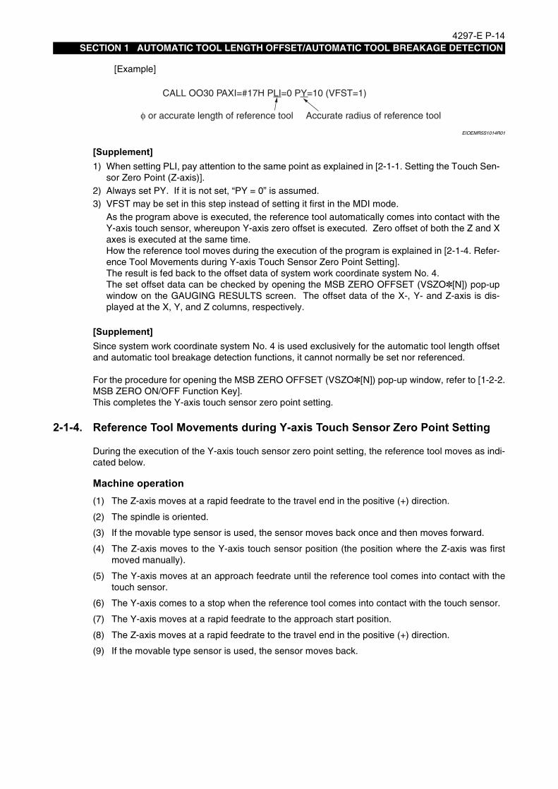
[Example]
EIOEMR5S1014R01
[Supplement]
[Supplement]
For the procedure for opening the MSB ZERO OFFSET (VSZO✽[N]) pop-up window, refer to [1-2-2.MSB ZERO ON/OFF Function Key].This completes the Y-axis touch sensor zero point setting.
2-1-4. Reference Tool Movements during Y-axis Touch Sensor Zero Point Setting
Eeoemr5s1015During the execution of the Y-axis touch sensor zero point setting, the reference tool moves as indi-cated below.
Machine operation(1) The Z-axis moves at a rapid feedrate to the travel end in the positive (+) direction.
(2) The spindle is oriented.
(3) If the movable type sensor is used, the sensor moves back once and then moves forward.
(4) The Z-axis moves to the Y-axis touch sensor position (the position where the Z-axis was firstmoved manually).
(5) The Y-axis moves at an approach feedrate until the reference tool comes into contact with thetouch sensor.
(6) The Y-axis comes to a stop when the reference tool comes into contact with the touch sensor.
(7) The Y-axis moves at a rapid feedrate to the approach start position.
(8) The Z-axis moves at a rapid feedrate to the travel end in the positive (+) direction.
(9) If the movable type sensor is used, the sensor moves back.
1) When setting PLI, pay attention to the same point as explained in [2-1-1. Setting the Touch Sen-sor Zero Point (Z-axis)].
2) Always set PY. If it is not set, “PY = 0” is assumed.3) VFST may be set in this step instead of setting it first in the MDI mode.
As the program above is executed, the reference tool automatically comes into contact with theY-axis touch sensor, whereupon Y-axis zero offset is executed. Zero offset of both the Z and Xaxes is executed at the same time.How the reference tool moves during the execution of the program is explained in [2-1-4. Refer-ence Tool Movements during Y-axis Touch Sensor Zero Point Setting].The result is fed back to the offset data of system work coordinate system No. 4.The set offset data can be checked by opening the MSB ZERO OFFSET (VSZO✽[N]) pop-upwindow on the GAUGING RESULTS screen. The offset data of the X-, Y- and Z-axis is dis-played at the X, Y, and Z columns, respectively.
Since system work coordinate system No. 4 is used exclusively for the automatic tool length offsetand automatic tool breakage detection functions, it cannot normally be set nor referenced.
CALL OO30 PAXI=#17H PLI=0 PY=10 (VFST=1)
φ or accurate length of reference tool Accurate radius of reference tool

4297-E P-15SECTION 1 AUTOMATIC TOOL LENGTH OFFSET/AUTOMATIC TOOL BREAKAGE DETECTION
2-2. Setting the Tool Pot No./Tool No. TableEeoemr5s1016Set the correspondence between tool numbers and tool pot numbers in the tool pot number - tool
number correspondence table.The table setting shown below uses a machine with 10-tool capacity magazine as an example.
EIOEMR5S1015R01
The tool offset data obtained by the execution of an automatic tool length offset cycle is set for thesame offset number as the tool number of the tool presently being used (active tool).Similarly, thetool offset number referred to and compared when the automatic tool breakage detection cycle isexecuted is the same offset number as the tool number of the active tool.
[Supplement]To automatically change a tool for a spare tool, tools must be registered in a tool group.For the procedure for registering tools in a group, refer to the Tool Management Function section ofthe special specifications of the Operation Manual.
Toolpot Number
Correspondence Table
Magazine capacity: 10 tools
1
2
3
4
5
6
7
8
9
10
Tool Number Write the correspondence between the tool number and the pot number on the screen when tools in the magazine are to be changed for new setup.
The total number of tools user for cutting the various types of workpieces is 300.
Assign a tool numberto each tool.
The memory of the OSP can hold the lifeexpectancy data of up to 300 tools.
Max. tool number: Standard 50 Option 300
1
2
3
20
30
31
32
105
270
271

4297-E P-16SECTION 1 AUTOMATIC TOOL LENGTH OFFSET/AUTOMATIC TOOL BREAKAGE DETECTION
2-3. Operation Mode DesignationEeoemr5s1017The basic operation mode of automatic tool length offset and automatic tool breakage detection is
designated by the system variable VFST.Since the system variable VFST is backed up in the CNC memory, it only has to be designatedonce: it does not have to be set each time the MSB of the automatic tool length offset/automatic toolbreakage detection cycle is called.VFST consists of one byte (8 bits) and each bit has the following significance.
EIOEMR5S1016R01
Bit No Setting Description
Bit 00 Automatic tool breakage detection cycle
1 Automatic tool length offset cycle
Bit 1 1Executes the automatic tool length offset/automatic tool breakage detec-tion cycle in the Y-axis direction.
Bit 2 1
Executes the automatic tool length offset/automatic tool breakage detec-tion cycle in the Y-axis direction after the execution of the automatic tool length offset/automatic tool breakage detection cycle in the Z-axis direc-tion.To execute automatic tool length offset/automatic tool breakage detec-tion cycle only in the Z-axis direction, set “0” for both Bit 1 and Bit 2.
Bit 3 1
Does not move the X-axis when positioning a reference tool at the touch sensor position.Set “1” for Bit 3 with machine models such as MCV in which the touch sensor is installed independently of the X-axis movement.
Bit 4 0 Always set “0”.
Bit 5 0 Always set “0”.
Bit 6 0 Always set “0”.
Bit 7
0Designates the relative offset type.The tool length in reference to the reference tool used for zero point set-ting of a work coordinate system is used as the tool length offset data.
1Designates the absolute offset type.The length of the tool from the spindle nose surface is regarded as the tool length offset data.
VFST Bit 7 Bit 6 Bit 5 Bit 4 Bit 3 Bit 2 Bit 1 Bit 0

4297-E P-17SECTION 1 AUTOMATIC TOOL LENGTH OFFSET/AUTOMATIC TOOL BREAKAGE DETECTION
An example of VFST settings is given in the following table.
[Supplement]
ModelRelative/Absolute
Offset Type
X-axis Movement
Yes/NoZ-axis/Y-axis Offset
Automatic Tool Length Off-set/Automatic Tool Break-
age Detection
VFST Value
MC-HMC-V
Relative offset
Yes Only Z-axis offsetAutomatic tool length offset #01H
Automatic tool breakage detection
#00H
Absolute offset
Yes Only Z-axis offsetAutomatic tool length offset #81H
Automatic tool breakage detection
#80H
MCVMCRMCM
(Vertical spindle)
Relative offset
No
Only Z-axis offsetAutomatic tool length offset #09H
Automatic tool breakage detection
#08H
Only Y-axis offsetAutomatic tool length offset #0BH
Automatic tool breakage detection
#0AH
Y-axis offset after Z-axis offset
Automatic tool length offset #0DH
Automatic tool breakage detection
#0CH
Absolute offset
No
Only Z-axis offsetAutomatic tool length offset #89H
Automatic tool breakage detection
#88H
Only Y-axis offsetAutomatic tool length offset #8BH
Automatic tool breakage detection
#8AH
Y-axis offset after Z-axis offset
Automatic tool length offset #8DH
Automatic tool breakage detection
#8CH
Refer to [3-1. Automatic Tool Length Offset/Automatic Tool Breakage Detection Function for Hori-zontal Tools of MCM] for details of automatic tool length offset/automatic tool breakage detectionfor the horizontal tools of MCM horizontal.

4297-E P-18SECTION 1 AUTOMATIC TOOL LENGTH OFFSET/AUTOMATIC TOOL BREAKAGE DETECTION
2-4. Automatic Tool Length Offset FunctionEeoemr5s1018The automatic tool length offset function automatically corrects the tool length according to the off-
set data set using the reference tool.
2-4-1. Z-axis Automatic Tool Length Offset
Eeoemr5s1019Automatic tool length offset in the Z-axis direction is executed in the manner indicated below.
NOTICE
Procedure :
1 After selecting the MDI mode, input “VFST=✽✽”, and press the CYCLE START button.Set an appropriate value for "✽✽" by referring to [2-3. Operation Mode Designation].The set value can be confirmed by opening the VARIOUS DATA pop-up window on the GAUG-ING RESULTS screen. Refer to [1-2-5. VARIOUS ON/OFF Function Key].
2 Mount the tool for which automatic tool length offset is to be executed in the spindle.When the tool is mounted in the spindle manually, make sure that the active tool number dis-played on the ATC TOOL DISPLAY (MEMORY RANDOM) screen (for the ATC memory randomspecification) or the POT NO./TOOL NO. TABLE (FIXED ADDRESS) screen (for the ATC fixedaddress specification) agrees with the tool number of the tool mounted in the spindle.This operation is not necessary when the tool is mounted in the spindle by executing the M06command, either in automatic or MDI operation.
3 Execute the following program after selecting the automatic mode.CALL OO30 (VFST=✽✽) (PLI = Anticipated tool length)M02When the program is executed, the tool is automatically brought into contact with the Z-axistouch sensor and the tool length offset data is calculated and stored in the CNC memory.The set tool length offset data can be checked by displaying the TOOL LENGTH OFFSET/CUTTER RADIUS COMPENSATION screen of the TOOL DATA screen.
Make sure that the zero point of the Z-axis touch sensor has been set before executing Z-axisautomatic tool length offset. Never execute Z-axis automatic tool length offset when the Z-axistouch sensor zero point has not been set.

4297-E P-19SECTION 1 AUTOMATIC TOOL LENGTH OFFSET/AUTOMATIC TOOL BREAKAGE DETECTION
The obtained results are also displayed on the GAUGING RESULTS screen
EIOEMR5S1017R01
This ends the Z-axis automatic tool length offset processing.
[Supplement]
Machine operationDuring the execution of the Z-axis automatic tool length offset, the tool moves as indicated below.
(1) The Z-axis moves at a rapid feedrate to the travel end in the positive (+) direction.
(2) The spindle is oriented.
(3) The X- and Y-axis move at a rapid feedrate to align the tool nose with the center of the touchsensor.For tools whose nose is not at the center of the spindle, refer to items (6) PX and (7) PY in [6-3.Explanation of Variables].
(4) The Z-axis moves at a fast approach feedrate until the tool comes into contact with the touchsensor.
(5) The Z-axis comes to a stop when the reference tool comes into contact with the touch sensor.
(6) The Z-axis moves back several millimeters at a rapid feedrate.
(7) The Z-axis moves at an approach feedrate until the tool comes into contact with the touch sen-sor again.
(8) The Z-axis comes to a stop when the reference tool comes into contact with the touch sensor.The result of gauging is stored under the same tool length offset number as the tool number ofthe active tool.
(9) The Z-axis moves at a rapid feedrate to the travel end in the positive (+) direction.
1) VFST may be set in this step instead of setting it first in the MDI mode. 2) Set the anticipated tool length for PLI.
If no value is set for PLI, the value set for CNC optional parameter (long word) No. 43 (distancefrom the spindle gauge line) is automatically set as the anticipated tool length.
4297-E P-20SECTION 1 AUTOMATIC TOOL LENGTH OFFSET/AUTOMATIC TOOL BREAKAGE DETECTION
2-4-2. Y-axis Automatic Tool Length Offset
Eeoemr5s1021Automatic tool length offset in the Z-axis direction is executed in the manner indicated below.
NOTICE
Procedure :
1 After selecting the MDI mode, input “VFST=✽✽”, and press the CYCLE START button.Set an appropriate value for "✽✽" by referring to [2-3. Operation Mode Designation].The set value can be confirmed by opening the VARIOUS DATA pop-up window on the GAUG-ING RESULTS screen. Refer to [1-2-5. VARIOUS ON/OFF Function Key].
2 Mount the tool for which Y-axis automatic tool length offset is to be executed in the spindle.When the tool is mounted in the spindle manually, make sure that the active tool number dis-played on the ATC TOOL DISPLAY (MEMORY RANDOM) screen (for the ATC memory randomspecification) or the POT NO./TOOL NO. TABLE (FIXED ADDRESS) screen (for the ATC fixedaddress specification) agrees with the tool number of spindle mounted tool.This operation is not necessary when the tool is mounted in the spindle by executing the M06command either in automatic or MDI operation.
3 Execute the following program after selecting the automatic mode.CALL OO30 PY= Anticipated cutter radius(VFST=✽✽)M02When the program is executed, the tool is automatically brought into contact with the Y-axistouch sensor and the cutter radius compensation data is calculated and stored in the CNCmemory.The set cutter radius compensation data can be checked by displaying the TOOL LENGTHOFFSET/CUTTER RADIUS COMPENSATION screen of the TOOL DATA screen. Theobtained results are also displayed at the GAUGING RESULTS screen.This ends the Y-axis automatic tool length offset processing.
[Supplement]
1) Make sure that the zero point of the Z-axis and Y-axis touch sensors has been set before exe-cuting Y-axis automatic tool length offset. Never execute Y-axis automatic tool length offsetwhen the touch sensor zero point has not been set.
2) Before executing automatic tool length offset in the Y-axis direction, set the Z-axis tool lengthoffset data of the tools.The Z-axis tool length offset data can be set either by executing the Z-axis automatic toollength offset or by inputting an appropriate value at the TOOL DATA screen.
VFST may be set in this step instead of setting it first in the MDI mode.

4297-E P-21SECTION 1 AUTOMATIC TOOL LENGTH OFFSET/AUTOMATIC TOOL BREAKAGE DETECTION
Machine operationDuring the execution of the Y-axis automatic tool length offset, the tool moves as indicated below.
(1) The Z-axis moves at a rapid feedrate to the travel end in the positive (+) direction.
(2) The spindle is oriented.
(3) The X- and Y-axis move at a rapid feedrate to align the tool nose with the center of the Z-axistouch sensor.
(4) The Z-axis moves at a fast approach feedrate to align the tool nose with the center of the Y-axistouch sensor.
(5) The Y-axis moves at an approach feedrate until the tool comes into contact with the Y-axis touchsensor.
(6) The Y-axis comes to a stop when the tool comes into contact with the touch sensor.The result of gauging is stored under the same cutter radius compensation number as the toolnumber of the active tool.
(7) The Y-axis returns at a rapid feedrate.
(8) The Z-axis moves at a rapid feedrate to the travel end in the positive (+) direction.
2-4-3. Continuous Z-axis and Y-axis Automatic Tool Length OffsetEeoemr5s1023To execute automatic tool length offset on the Z-axis and the Y-axis continuously, follow the proce-
dure indicated below.For points of caution and details of the tool length offset, refer to [2-4-1. Z-axis Automatic ToolLength Offset] and [2-4-2. Y-axis Automatic Tool Length Offset].
Procedure :
1 After selecting the MDI mode, input “VFST=✽✽”, and press the CYCLE START button.
2 Execute the following program after selecting the automatic mode.CALL OO30 PY= Anticipated cutter radius (PLI = Anticipated tool length) (VFST=✽✽)M02The tool is first brought into contact with the Z-axis touch sensor then the Y-axis touch sensor.This ends the continuous Z-axis and Y-axis automatic tool length offset processing.
4297-E P-22SECTION 1 AUTOMATIC TOOL LENGTH OFFSET/AUTOMATIC TOOL BREAKAGE DETECTION
2-5. Setting the Tool Change Position (Other Than MC-H)Eeoemr5s1024When a tool is found to be broken in the automatic tool breakage detection cycle, the broken tool
can be automatically returned to the magazine by using a subprogram.In order to execute this automatic tool return cycle, the tool change position must be set for MC-Vand double-column machining centers since these types of machining centers do not have a presetATC home position like MC-H.If the tool change position is not set for these types of machining centers, the tool change will be car-ried out just above the touch sensor. Since this may cause problems with some kinds of work-pieces, it is necessary to set the tool change position for MC-V and double-column machiningcenters.
Procedure :
1 Move the spindle to the desired tool change position.Note that X- and Y-axis must be positioned at the desired tool change position. Positioning ofthe Z-axis is not necessary.
2 At this position, execute the following program after selecting the automatic mode.CALL OO31M02The axes will not move at all even when a program is executed.The set tool change position data can be checked by opening the MSB ZERO OFFSET(VSZO✽[N]) pop-up window on the GAUGING RESULTS screen. The tool change positiondata of the X-, Y- and Z-axis is displayed at the X, Y, and Z columns of the NO. 2 line.This completes the tool change position setting.
[Supplement]Since system work coordinate system No. 2 is used exclusively for the automatic tool length offsetand automatic tool breakage detection functions, it cannot normally be set or referenced.

4297-E P-23SECTION 1 AUTOMATIC TOOL LENGTH OFFSET/AUTOMATIC TOOL BREAKAGE DETECTION
2-6. Automatic Tool Breakage Detection
2-6-1. Z-axis Automatic Tool Breakage DetectionEeoemr5s1025Automatic tool breakage detection in the Z-axis direction is executed in the manner indicated below.
NOTICE
Procedure :
1 After selecting the MDI mode, input “VFST=✽✽”, and press the CYCLE START button.Set an appropriate value for "✽✽" by referring to [2-3. Operation Mode Designation].
2 Mount the tool for which automatic tool breakage detection is to be executed in the spindle.When the tool is mounted in the spindle manually, make sure that the active tool number dis-played on the ATC TOOL DISPLAY (MEMORY RANDOM) screen (for the ATC memory randomspecification) or the POT NO./TOOL NO. TABLE (FIXED ADDRESS) screen (for the ATC fixedaddress specification) agrees with the tool number of the tool mounted in the spindle.This operation is not necessary when the tool is mounted in the spindle by executing the M06command either in automatic or MDI operation.
3 Execute the following program after selecting the automatic mode.CALL OO30 PLE1 PLE1= Tool breakage judgment value (PGO=✽✽)M02When the program is executed, the tool is automatically brought into contact with the touchsensor and the tool length is obtained.The obtained tool length is compared to the tool length offset data stored in the CNC memoryand a tool breakage alarm occurs if the difference is greater than the value set for PLE1.The tool breakage alarm also occurs if the tool nose fails to contact the touch sensor during theexecution of the program.This ends the Z-axis automatic tool breakage detection processing.
[Supplement]
Before executing Z-axis automatic tool breakage detection, make sure that the zero point of thetouch sensor and the tool change position have been set.
1) VFST may be set in this step instead of setting it first in the MDI mode. 2) To replace a broken tool with a spare tool, PGO must be designated.
For details of PGO, refer to item (11) PGO(P GO) in [6-3. How to Use Variables].

4297-E P-24SECTION 1 AUTOMATIC TOOL LENGTH OFFSET/AUTOMATIC TOOL BREAKAGE DETECTION
Machine operationDuring the execution of the Z-axis automatic tool breakage detection, the tool moves as indicatedbelow.
(1) The Z-axis moves at a rapid feedrate to the travel end in the positive (+) direction.
(2) The spindle is oriented.
(3) The X- and Y-axis move at a rapid feedrate to align the tool nose with the center of the Z-axistouch sensor.For tools whose nose is not at the center of the spindle, refer to items (6) PX and (7) PY in [6-3.Explanation of Variables].
(4) The Z-axis moves at a fast approach feedrate until the tool nose reaches the position 20 mmaway from the touch sensor.
(5) The Z-axis moves at an approach feedrate to the position 10 mm past the point where the toolnose would be in contact with the touch sensor.
• If the tool has not been broken or the amount of chipping is smaller than 10 mm:The tool nose comes into contact with the touch sensor and the Z-axis stops. The toollength is calculated from the coordinate value of the contact position and is stored in theCNC memory temporarily.
• If the tool has been broken (amount of chipping is greater than 10 mm):The tool nose will not contact the touch sensor.
(6) The Z-axis moves at a rapid feedrate to the travel end in the positive (+) direction.

4297-E P-25SECTION 1 AUTOMATIC TOOL LENGTH OFFSET/AUTOMATIC TOOL BREAKAGE DETECTION
2-6-2. Y-axis Automatic Tool Breakage Detection
Eeoemr5s1027Automatic tool breakage detection in the Y-axis direction is executed in the manner indicated below.
NOTICE
Procedure :
1 After selecting the MDI mode, input “VFST=✽✽”, and press the CYCLE START button.Set an appropriate value for "✽✽" by referring to [2-3. Operation Mode Designation].
2 Mount the tool for which automatic tool breakage detection is to be executed in the spindle.When the tool is mounted to the spindle manually, make sure that the active tool number dis-played on the ATC TOOL DISPLAY (MEMORY RANDOM) screen (for the ATC memory randomspecification) or the POT NO./TOOL NO. TABLE (FIXED ADDRESS) screen (for the ATC fixedaddress specification) agrees with the tool number of the tool mounted in the spindle.This operation is not necessary when the tool is mounted in the spindle by executing the M06command either in automatic or MDI operation.
3 Execute the following program after selecting the automatic mode.CALL OO30 PLEY=Tool breakage judgment value PY=Anticipated cutter radius (VFST=✽✽)M02When the program is executed, the tool is automatically brought into contact with the touchsensor and the cutter radius is obtained.The obtained cutter radius is compared to the cutter radius compensation data stored in theCNC memory and a tool breakage alarm occurs if the difference is greater than the value setfor PLEY.The tool breakage alarm also occurs if the tool fails to contact the touch sensor during the exe-cution of the program.This ends the Y-axis automatic tool breakage detection processing.
[Supplement]
Before executing Z-axis automatic tool breakage detection, make sure that the zero point of thetouch sensor has been set.
1) VFST may be set in this step instead of setting it first in the MDI mode. 2) To replace a broken tool with a spare tool, PGO must be designated.

4297-E P-26SECTION 1 AUTOMATIC TOOL LENGTH OFFSET/AUTOMATIC TOOL BREAKAGE DETECTION
Machine operationDuring the execution of the Y-axis automatic tool breakage detection, the tool moves as indicatedbelow.
(1) The Z-axis moves at a rapid feedrate to the travel end in the positive (+) direction.
(2) The spindle is oriented.
(3) The X- and Y-axis move at a rapid feedrate to align the tool nose with the center of the touchsensor.
(4) The Z-axis moves at a rapid feedrate to align the tool nose with the center of the Y-axis touchsensor.
(5) The Y-axis moves at an approach feedrate to the position 10 mm past the point where the toolnose would be in contact with the touch sensor.
• If the tool has not been broken or amount of chipping is smaller than 10 mm:The tool nose comes into contact with the touch sensor and the Y-axis stops. The cutterradius is calculated from the coordinate value of the contact position and is stored in theCNC memory temporarily.
• If the tool has been broken (amount of chipping is greater than 10 mm):The tool nose will not contact the touch sensor.
(6) The Y-axis returns at a rapid feedrate.
(7) The Z-axis moves at a rapid feedrate to the travel end in the positive (+) direction.
2-6-3. Continuous Z-axis and Y-axis Automatic Tool Breakage Detection
Eeoemr5s1028To execute automatic tool breakage detection on the Z-axis and the Y-axis continuously, follow theprocedure indicated below.For items carefully attended to and details of the tool length offset, refer to [2-6-1. Z-axis AutomaticTool Breakage Detection] and [2-6-2. Y-axis Automatic Tool Breakage Detection].
Procedure :
1 After selecting the MDI mode, input “VFST=✽✽” and press the CYCLE START button.
2 Execute the following program after selecting the automatic mode.
EIOEMR5S1018R01
3 The tool is first brought into contact with the Z-axis touch sensor to check tool breakage in theZ-axis direction. When tool breakage is not detected in the Z-axis direction, tool breakage inthe Y-axis direction is checked.
CALL OO30 (VFST=**) PY=Anticipated cutter radius PLE1=Tool breakage judgment value (Z-axis)PLEY=Tool breakage judgment value (Y-axis)
M02

4297-E P-27SECTION 1 AUTOMATIC TOOL LENGTH OFFSET/AUTOMATIC TOOL BREAKAGE DETECTION
2-6-4. Judgment of Tool Breakage
Eeoemr5s1029When a spare tool is selected in response to the detection of tool breakage, operation does not stopeven when the breakage is detected. Therefore, it is necessary to judge the occurrence of toolbreakage at the end of the automatic tool breakage detection cycle and branch the program execu-tion in accordance with the result of the judgement.
• It can be judged whether or not the tool is broken by reading system variable VOK1.VOK1 = 0 Tool is not broken.VOK1 ≠ 0 Tool is broken.VOK1 indicates the result of the previously executed automatic tool breakage detection cycle.
• Another system variable VOK2 is also available for judgement.VOK2 indicates the result of automatic tool breakage detection cycles executed after clearanceto 0 (VOK2 = 0). If tool breakage is detected even once, the value set for VOK2 is “VOK2 ≠ 0”.
• VOK1 and VOK2 are not cleared to 0 when the CNC is reset.
[Supplement]When tool breakage is detected by the automatic tool breakage detection function, the tool numberis registered by the tool management function as that of a broken tool.In order to use the same tool number after taking the necessary measures, such as replacementwith a new tool, the registration of the broken tool number must be cleared.Refer to Tool Management Function in special specifications of the Operation Manual for the proce-dure for resetting broken tool registration.

4297-E P-28SECTION 1 AUTOMATIC TOOL LENGTH OFFSET/AUTOMATIC TOOL BREAKAGE DETECTION
2-7. Cycle Time Reduction for Automatic Tool Length Offset/Automatic Tool Breakage Detection Cycle
Eeoemr5s1031By feeding a tool close to the sensor at a rapid feedrate, it is possible to reduce the cycle time of theautomatic tool length offset/automatic tool breakage detection cycle.
Fig.1-1 Cycle Time Reduction FunctionEIOEMR5S1019R01
To use this function, it is necessary to set the following parameters.
• Optional parameter (bit) No. 36, bit 3:Default of maximum tool length for automatic tool length offset/tool breakage detectionWith check mark: ValidWithout check mark: Invalid (Initial value)
• Optional parameter (long ward) No. 44: Max. tool lengthFor this parameter, set the maximum tool length among the tools that will be used.Setting range: 0 to 999Unit: mmInitial setting: 0
CAUTIONSet an appropriate value for the maximum tool length setting parameter since “0” is set asthe initial value.
Spindle nose face
Tool
Anticipatedtool length
PL1
Max. tool lengthVLTL
Safety distancePUDT
Sensor
G31F2000G31F=PF1 (5)
(6)
G0 (4)

4297-E P-29SECTION 1 AUTOMATIC TOOL LENGTH OFFSET/AUTOMATIC TOOL BREAKAGE DETECTION
2-7-1. Automatic tool length offset cycle
Eeoemr5s1090Machine operation(1) The Z-axis moves at a rapid feedrate to the travel end in the positive (+) direction.
(2) The spindle is oriented.
(3) The X- and Y-axis move at a rapid feedrate to align the tool nose with the center of the touchsensor.
(4) The Z-axis moves at a rapid feedrate to the point distanced from the touch sensor by “safety dis-tance (PUDT) + max. tool length (VLTL)”.This operation is or is not executed according to the setting for the parameter.
(5) The Z-axis moves at a skip feedrate, specified by PF1, to the point distanced from the touchsensor by “anticipated tool length (PLI) + safety distance (PUDT)”.If the PLI command is not specified, the Z-axis moves at a skip feedrate specified by PF1 to thepoint distanced from the touch sensor by “safety distance (PUDT)”. If the PF1 command is notspecified, the Z-axis moves at F2000.
(6) The Z-axis moves at F2000 to the point 10 mm beyond the anticipated contact point.It stops when the tool comes into contact with the touch sensor.
(7) The Z-axis returns 5 mm from the contact point.
(8) The Z-axis moves at a skip feedrate, specified by PF2, to the point 10 mm beyond the contactpoint.It stops when the tool comes into contact with the touch sensor.
(9) The tool length offset data is written to the active tool number or the offset number specified bythe PH command.
(10) The Z-axis moves at a rapid feedrate to the travel end in the positive (+) direction.
2-7-2. Automatic tool breakage detection cycle
Eeoemr5s1091Machine operation(1) The same operation as steps 1) to 4) of the automatic tool length offset cycle explained above is
executed.
(2) The Z-axis moves at skip feedrate F4000 to the point 5 mm away the anticipated contact point.
(3) The Z-axis moves at skip feedrate F1000 to the point 10 mm beyond the anticipated contactpoint. It stops when the tool comes into contact with the touch sensor.
(4) The Z-axis moves at a rapid feedrate to the travel end in the positive (+) direction.

4297-E P-30SECTION 1 AUTOMATIC TOOL LENGTH OFFSET/AUTOMATIC TOOL BREAKAGE DETECTION
2-8. New Cycle Time Reduction Function for Automatic Tool Length Offset/Automatic Tool Breakage Detection Cycle
Eeoemr5s1032By reducing the execution time of the cycle steps that can be reduced in the previous automatic toollength offset/automatic tool breakage detection cycle, the cycle time reduction function is mademore powerful.This new cycle time reduction function is usable only in the vertical tool direction.
2-8-1. Command Format and Variables of the New Cycle Time Reduction FunctionEeoemr5s1033The command format and the variables used by the new cycle time reduction function are described
below.
• Command formatThe following is an example command to use the cycle time reduction function.CALL OO30 PZRC=1 PSFT=10 POVT=20 PF1=5000 PF2=2000 M02
• Variables
PZRC Used to select the new or conventional cycle time reduction function.“1” selects the new cycle time reduction function and “0” selects the conventional cycle time reduction function. The default is “0”.
PUDT: Undertravel distance (safety distance)This defines the point where, during the approach of a cutting tool to the touch sensor, the approach speed is changed from high-speed to low-speed. The dis-tance from the touch sensor to the tool nose is designated.For the automatic tool breakage detection cycle, the default is 5 mm.
POVT: Overtravel distance (sensor breakage prevention distance)Default is 10 mm.
PFA: Approach speed to undertravel pointFor the automatic tool breakage detection cycle, the default is F4000 mm/min.
PF2: Approach speed to overtravel pointFor the automatic tool breakage detection cycle, the default is F1000 mm/min.
VMSBU: Setting for CNC optional parameter (bit) No. 36If the setting for bit 3 of this parameter is “1”, with “0” set for PZRC, the conven-tional cycle time reduction function is selected.
VLTL: Maximum tool lengthThe value set for CNC optional parameter (long word) No. 44
PSFT: Feedrate shift distanceThis defines the point where, during approach of a cutting tool to the touch sensor, the approach speed is changed from a rapid feedrate to high-speed (low-speed if PSFT is not specified). The distance from the touch sensor to the tool nose is designated.The default is 5 mm.

4297-E P-31SECTION 1 AUTOMATIC TOOL LENGTH OFFSET/AUTOMATIC TOOL BREAKAGE DETECTION
2-8-2. Tool Movements of New Cycle Time Reduction Function
Eeoemr5s1034During the execution of the new cycle time reduction function, the tool moves as indicated below.Note that tool movements differ according to the setting of the variables.
Variable setting: PZRC = 0, Bit 3 of VMSBU = 0
Machine operation(1) The Z-axis moves at a rapid feedrate to the travel end in the positive (+) direction
(2) The spindle is oriented.
(3) The Y-axis and the X-axis, in this order, move at a rapid feedrate to align the tool nose with thecenter of the touch sensor.
(4) The Z-axis moves at a skip feedrate, specified by PFA, to the position PUDT above the touchsensor zero point.The Z-axis stops when the tool comes into contact with the sensor.
(5) The Z-axis moves at a skip feedrate, specified by PF2, to the position POVT below the touchsensor zero point.The Z-axis stops when the tool comes into contact with the sensor.
(6) The Z-axis moves at a rapid feedrate to the travel end in the positive (+) direction.
EIOEMR5S1020R01
2)
Rapid feed 3)
Rap
id fe
ed 1
)
PFA
4)
Rap
id fe
ed 6
)
Touch sensor zero point
PF2 5) PUDTPOVT
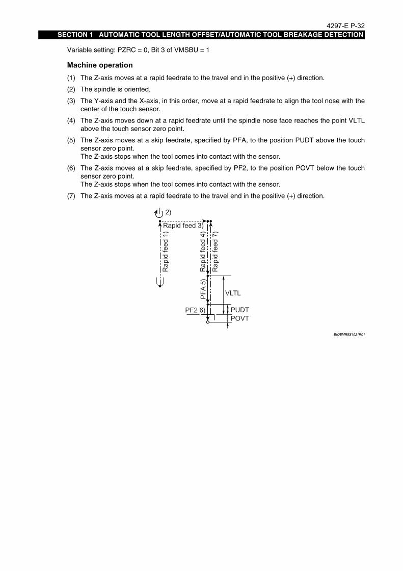
4297-E P-32SECTION 1 AUTOMATIC TOOL LENGTH OFFSET/AUTOMATIC TOOL BREAKAGE DETECTION
Variable setting: PZRC = 0, Bit 3 of VMSBU = 1
Machine operation(1) The Z-axis moves at a rapid feedrate to the travel end in the positive (+) direction.
(2) The spindle is oriented.
(3) The Y-axis and the X-axis, in this order, move at a rapid feedrate to align the tool nose with thecenter of the touch sensor.
(4) The Z-axis moves down at a rapid feedrate until the spindle nose face reaches the point VLTLabove the touch sensor zero point.
(5) The Z-axis moves at a skip feedrate, specified by PFA, to the position PUDT above the touchsensor zero point.The Z-axis stops when the tool comes into contact with the sensor.
(6) The Z-axis moves at a skip feedrate, specified by PF2, to the position POVT below the touchsensor zero point.The Z-axis stops when the tool comes into contact with the sensor.
(7) The Z-axis moves at a rapid feedrate to the travel end in the positive (+) direction.
EIOEMR5S1021R01
2)
Rapid feed 3)
Rap
id fe
ed 1
)
PFA
5)
Rap
id fe
ed 7
)
Rap
id fe
ed 4
)
PF2 6) PUDTPOVT
VLTL

4297-E P-33SECTION 1 AUTOMATIC TOOL LENGTH OFFSET/AUTOMATIC TOOL BREAKAGE DETECTION
Variable setting: PZRC = 1, Bit 3 of VMSBU = 0 or 1If “PUDT > PSFT”, an alarm (Alarm B 2305 UNTENDED: gauging impossible 64) occurs.
Machine operation(1) If the tool nose is below the point “touch sensor zero point + PSFT”, the Z-axis moves up at a
rapid feedrate to the point “touch sensor zero point + PSFT”
(2) The spindle is oriented.
(3) The Y-axis and the X-axis, in this order, move at a rapid feedrate to align the tool nose with thecenter of the touch sensor.
(4) The Z-axis moves down at a rapid feedrate to the point “touch sensor zero point + PSFT”.
(5) The Z-axis moves down at a skip feedrate PFA to the point “touch sensor zero point + PUDT”.
(6) The Z-axis moves down at a skip feedrate PF2 to the point “touch sensor zero point - POVT”.
(7) The Z-axis moves up at rapid feedrate to the point “touch sensor zero point + PSFT”.
EIOEMR5S1022R01
2)
2)
Rapid feed 3)
Rap
id fe
ed 1
)
Rap
id fe
ed 4
)
PFA 5)
PF2 6)
PSFTPUDTPOVT
Rapid feed 7)

4297-E P-34SECTION 1 AUTOMATIC TOOL LENGTH OFFSET/AUTOMATIC TOOL BREAKAGE DETECTION
3. Automatic Tool Length Offset/Automatic Tool Breakage Detection Function for Special Tools and Attachments
Eeoemr5s1035This section deals with the automatic tool length offset/automatic tool breakage detection functionfor special tools and attachments. If no such tools or attachments are used, this section may beskipped.
3-1. Automatic Tool Length Offset/Automatic Tool Breakage Detection Function for Horizontal Tools of MCM
Eeoemr5s1036The operation procedure for the automatic tool length offset/automatic tool breakage detection func-tion for horizontal tools of MCM is described below.
NOTICE
Machine operationDuring the execution of the automatic tool length offset/automatic tool breakage detection cycle forthe horizontal tool of MCM, the tool moves as indicated below.
(1) The Z-axis moves at a rapid feedrate to the travel end in the positive (+) direction.
(2) M76 and M19 are executed.The swivel head is indexed to the right position and the spindle is oriented.
(3) The Y-axis moves at a rapid feedrate to a position just before the touch sensor.
(4) The Z-axis moves at a rapid feedrate to the touch sensor position for the horizontal tool.
(5) From here on, the movements are the same as for a vertical tool.Note, however, that with an MCM horizontal tool, the Z-axis movements of a vertical tool arereplaced by the Y-axis movements of a horizontal tool.
EIOEMR5S1023R01
Since the machine operations for the automatic tool length offset/automatic tool breakage detec-tion function used for horizontal tools of MCM are similar to those for vertical tools of MCM, part ofthe explanation is omitted.For the information not given below, refer to [2. Automatic Tool Length Offset/Automatic ToolBreakage Detection Operation].
3)2)
1) 4)
5)

4297-E P-35SECTION 1 AUTOMATIC TOOL LENGTH OFFSET/AUTOMATIC TOOL BREAKAGE DETECTION
3-1-1. Setting the Z-axis Lower Limit Position
Eeoemr5s1038When executing the automatic tool length offset/automatic tool breakage detection cycle for an MCMhorizontal tool, the spindle may strike the workpiece during Z-axis downward operation.To avoid such a problem, it is necessary to set the Z-axis lower limit position as close to the touchsensor as possible, but at a position where the spindle or other machine unit will not collide with thetouch sensor unit.Set the Z-axis lower limit position in the manner indicated below.
Procedure :
1 Move the Y-axis to the position where the Z-axis lower limit position is to be set.In this operation, the X- and Z-axis may be at any position.
2 At this position, execute the following program after selecting the automatic mode.CALL OO32M02When this program is executed, axes do not move.After the execution of the program, the actual position of the Z-axis is stored in system workcoordinate system No. 9 as the Z-axis lower limit position.The set value can be checked by opening the MSB ZERO OFFSET (VSZO✽[N]) pop-up win-dow on the GAUGING RESULTS screen. The Z-axis lower limit coordinate value is displayedat the Y column of the NO. 9 line.
[Supplement]Since system work coordinate system No. 9 is used exclusively for automatic tool length offset andautomatic tool breakage detection functions, it cannot normally be set or referenced.

4297-E P-36SECTION 1 AUTOMATIC TOOL LENGTH OFFSET/AUTOMATIC TOOL BREAKAGE DETECTION
3-1-2. Designating the Operation Mode
Eeoemr5s1039As with a vertical tool, the basic operation mode for a horizontal tool is set using system variableVFST.The setting for system variable VFST is the same as that for a vertical spindle with the exception that“1” is set for bit 6.VFST consists of one byte (8 bits) and each bit has the following significance
EIOEMR5S1024R01
Bit No. Setting Description
Bit 00 Automatic tool breakage detection cycle
1 Automatic tool length offset cycle
Bit 1 1Executes the automatic tool length offset/automatic tool breakage detec-tion cycle in the Z-axis (radial) direction
Bit 2 1
Executes the automatic tool length offset/automatic tool breakage detec-tion cycle in the Z-axis (radial) direction after the execution of the auto-matic tool length offset/automatic tool breakage detection cycle in the Y-axis (tool length) direction.To execute an automatic tool length offset/automatic tool breakage detection cycle only in the Y-axis (tool length) direction, set “0” for both Bit 1 and Bit 2
Bit 3 1Does not move the X-axis when positioning a tool to the touch sensor position.
Bit 4 0 Always set “0”
Bit 5 0 Always set “0”.
Bit 60
Executes the automatic tool length offset/automatic tool breakage detec-tion cycle for a vertical tool.
1Executes the automatic tool length offset/automatic tool breakage detec-tion cycle for a horizontal tool.
Bit 7
0Designates the relative offset type.The tool length in reference to the reference tool used for zero point set-ting of a work coordinate system is used as the tool length offset data.
1Designates the absolute offset type.The length of the tool from the spindle nose surface is regarded as the tool length offset data
VFST Bit 7 Bit 6 Bit 5 Bit 4 Bit 3 Bit 2 Bit 1 Bit 0

4297-E P-37SECTION 1 AUTOMATIC TOOL LENGTH OFFSET/AUTOMATIC TOOL BREAKAGE DETECTION
An example of VFST settings is given in the following table.
ModelRelative/Absolute
Offset Type
X-axis Movement
Yes/No
Offset in Tool Length Direction/Tool Radial
Direction
Automatic Tool Length Off-set/Automatic Tool Break-
age Detection
VFST Value
MCMHorizon-tal tool
Relative offset
No
Offset only in the tool length direction
Automatic tool length offset #49H
Automatic tool breakage detection
#48H
Offset only in the tool radial direction
Automatic tool length offset #4BH
Automatic tool breakage detection
#4AH
Offset in the tool length direction then
the tool radial direction
Automatic tool length offset #4DH
Automatic tool breakage detection
#4CH
Absolute offset
No
Offset only in the tool length direction
Automatic tool length offset #C9H
Automatic tool breakage detection
#C8H
Offset only in the tool radial direction
Automatic tool length offset #CBH
Automatic tool breakage detection
#CAH
Offset in the tool length direction then
the tool radial direction
Automatic tool length offset #CDH
Automatic tool breakage detection
#CCH

4297-E P-38SECTION 1 AUTOMATIC TOOL LENGTH OFFSET/AUTOMATIC TOOL BREAKAGE DETECTION
3-1-3. Setting the Zero Point of Horizontal Tool Touch Sensor
Eeoemr5s1040Set the zero point of the touch sensor for MCM horizontal tools in the manner indicated below.
Procedure :
1 Select the MDI mode and execute M144 to move the reference tool near the horizontal tooltouch sensor.Since the procedure up to this step is the same as used for a vertical tool, refer to [2-1. Settingthe Touch Sensor Zero Point] for details.
2 Execute the following program after selecting the automatic mode.
• Setting the zero point for the tool length (Y-axis) direction touch sensorCALL OO30 PAXI=#27H PLI=0 (or accurate reference tool length) (VFST=✽✽)M02
• Setting the zero point for the tool radius (Z-axis) direction touch sensor
EIOEMR5S1025R01
The result of gauging is stored in the system work coordinate system No. 7 (zero point ofthe tool length direction (Y-axis direction) touch sensor) and the system work coordinatesystem No. 8 (zero point of the tool radius direction (Z-axis direction) touch sensor).The set value can be checked by opening the MSB ZERO OFFSET (VSZO✽[N]) pop-upwindow on the GAUGING RESULTS screen.
[Supplement]Before setting the zero point, index the swivel head to the following position.Vertical tool: Front position (M73)Horizontal tool: Right position (M76)
CALL OO30 PAXI=#47H PLI=0 (or accurate reference tool length) (VFST=**)PZ=Accurate radius of the reference tool
M02

4297-E P-39SECTION 1 AUTOMATIC TOOL LENGTH OFFSET/AUTOMATIC TOOL BREAKAGE DETECTION
3-1-4. Automatic Tool Length Offset for Horizontal Tools
Eeoemr5s1041Automatic tool length offset for horizontal tools is executed in the manner indicated below.
NOTICE
Procedure :
1 After selecting the MDI mode, input “VFST=✽✽”, and press the CYCLE START button.Set an appropriate value for "✽✽" by referring to [3-1-2. Designating the Operation Mode].
2 Mount the tool for which automatic tool length offset should be executed in the spindle.
3 Execute the following program after selecting the automatic mode.
• In the tool length (Y-axis) directionCALL OO30 (VFST=Appropriate value) (PLI=Anticipated tool length)M02
• In the tool radius (Z-axis) directionCALL OO30 (VFST=Appropriate value) PZ=Anticipated tool radiusM02
• Both in the tool length (Y-axis) direction and the tool radius (Z-axis) directionCALL OO30 (VFST=Appropriate value) PZ=Anticipated tool radius (PLI=Anticipated toollength)M02
When the program is executed, the tool is automatically brought into contact with the touchsensor and the cutter radius compensation data is calculated and stored in the CNC memory.The result of gauging can be checked by displaying the TOOL LENGTH OFFSET/CUTTERRADIUS COMPENSATION screen of the TOOL DATA screen. The obtained results are alsodisplayed on the GAUGING RESULTS screen.
Before executing automatic tool length offset for horizontal tools, make sure that the zero point ofthe horizontal tool touch sensor has been set

4297-E P-40SECTION 1 AUTOMATIC TOOL LENGTH OFFSET/AUTOMATIC TOOL BREAKAGE DETECTION
3-1-5. Automatic Tool Breakage Detection Cycle for Horizontal Tools
Eeoemr5s1042Automatic tool breakage detection for horizontal tools is executed in the manner indicated below.
NOTICE
Procedure :
1 After selecting the MDI mode, input “VFST=✽✽”, and press the CYCLE START button.Set an appropriate value for "✽✽" by referring to [3-1-2. Designating the Operation Mode].
2 Mount the tool for which automatic tool breakage detection should be executed in the spindle.
3 Execute the following program after selecting the automatic mode.
• In the tool length (Y-axis) directionCALL OO30 PLE1=Tool breakage judgment value (VFST=Appropriate value)M02
• In the tool radius (Z-axis) directionCALL OO30 PLEZ=Tool breakage judgment value PZ=Anticipated tool radius(VFST=Appropriate value)M02
• Both in the tool length (Y-axis) direction and the tool radius (Z-axis) direction
EIOEMR5S1026R01
When the program is executed, the tool is automatically brought into contact with thetouch sensor, and the tool length is calculated.The function compares the obtained tool length to the tool length offset data stored in theCNC memory and judges the tool has been broken if the difference is greater than theset tool breakage judgment value.The result of gauging is displayed at the GAUGING RESULTS screen.
[Supplement]
Before executing automatic tool breakage detection for horizontal tools, make sure that the zeropoint of the horizontal tool touch sensor has been set.
Before executing tool length offset/tool breakage detection for horizontal tools, index the swivelhead to the following position.Vertical tool: Front position (M73)Horizontal tool: Right position (M76)All other supplements are the same as in the case of vertical tools.
CALL OO30 PZ=Anticipated tool radius PLE1=Tool breakage judgment value (tool length direction) PLEZ=Tool breakage judgment value (tool radius direction) (VFST=Appropriate value)
M02

4297-E P-41SECTION 1 AUTOMATIC TOOL LENGTH OFFSET/AUTOMATIC TOOL BREAKAGE DETECTION
3-2. Operation for Automatic Tool Length Offset/Automatic Tool Break-age Detection on B/C-axis Attachments, 90° Angular Attachments and Extension Attachments (Option)
Eeoemr5s1043This subsection describes the functions of automatic tool length offset/automatic tool breakagedetection for tools mounted in a B/C-axis attachment, 90° angular attachment, or extension attach-ment.
EIOEMR5S1027R01
Fig.1-2 Relationship between PAC Angles and X, Y, Z Axes of 90° Angular Attachment
EIOEMR5S1028R01
Fig.1-3 Relationship between PAC Angles and X, Y, Z Axes of B/C-axis Attachment
(PAC = 90°)
(PAC = 180°)
(PAC = 270°)
(PAC = 0°)
Z+
X+Y+
PAC = 90°
PAC = 180°
PAC = 270°
PAB
PAC = 0°
Z+
Y+X+

4297-E P-42SECTION 1 AUTOMATIC TOOL LENGTH OFFSET/AUTOMATIC TOOL BREAKAGE DETECTION
[Supplement]1) To use an attachment, index the PAB to 0° or 90°.2) Call the ATTACHMENT (PAC, PAB) SWIVEL COMPENSATION screen and set the data dis-
played there on the ATTACHMENT SWIVEL COMPENSATION screen.The correspondence between the items displayed on the ATTACHMENT (PAC, PAB) SWIVELCOMPENSATION screen and those on the ATTACHMENT SWIVEL COMPENSATION screenis indicated below.
EIOEMR5S1029R01
H*: Attachment compensation numbers H1 to H8If two B/C-axis attachments are used, set their data with separate compensation numbers.
ATTACHMENT (PAC, PAB)SWIVEL COMPENSATION
screen
ATTACHMENT SWIVELCOMPENSATION screen
Data for PAC = 0 PAB = 0 H* in the LOWER (G185) screen
Data for PAC = 0 PAB = 90 H* in the FRONT (G181) screen
Data for PAC = 90 PAB = 90 H* in the LEFT (G182) screen
Data for PAC = 180 PAB = 90 H* in the REAR (G183) screen
Data for PAC = 270 PAB = 90 H* in the RIGHT (G184) screen

4297-E P-43SECTION 1 AUTOMATIC TOOL LENGTH OFFSET/AUTOMATIC TOOL BREAKAGE DETECTION
3-2-1. Designating the Operation Mode
Eeoemr5s1044Use system variable “VFST” to designate the basic operation modes for automatic tool length offsetor automatic tool breakage detection.Since the system variable VFST is backed up in the CNC memory, it only has to be designatedonce: it does not have to be set each time the MSB of the automatic tool length offset/automatic toolbreakage detection cycle is called.VFST consists of one byte (8 bits) and each bit has the following significance
EIOEMR5S1030R01
Bit No. Setting Description
Bit 00 Automatic tool breakage detection cycle
1 Automatic tool length offset cycle
Bit 1 1Executes the automatic tool length offset/automatic tool breakage detec-tion cycle in the tool radius direction.
Bit 2 1
Executes the automatic tool length offset/automatic tool breakage detec-tion cycle in the tool radius direction after the execution of the automatic tool length offset/automatic tool breakage detection cycle in the tool length direction.To execute automatic tool length offset/automatic tool breakage detec-tion cycle only in the tool length direction, set “0” for both Bit 1 and Bit 2.
Bit 3 1
Does not move the X-axis when positioning a reference tool at the touch sensor position.Set “1” for Bit 3 for machine models such as MCV in which the touch sen-sor is installed independently of the X-axis movement.
Bit 4 0 Always set “0”
Bit 5 0 Always set “0”.
Bit 6
0Executes the automatic tool length offset/automatic tool breakage detec-tion cycle for a vertical tool or a tool in the extension attachment or the B/C-axis attachment (PAB = 0°).
1Executes the automatic tool length offset/automatic tool breakage detec-tion cycle for a tool in the 90° attachment or the B/C-axis attachment (PAB = 90°).
Bit 70 Designates the relative offset type.
1 Designates the absolute offset type.
VFST Bit 7 Bit 6 Bit 5 Bit 4 Bit 3 Bit 2 Bit 1 Bit 0

4297-E P-44SECTION 1 AUTOMATIC TOOL LENGTH OFFSET/AUTOMATIC TOOL BREAKAGE DETECTION
3-2-2. Command Format
Eeoemr5s1045The command format used for calling the automatic tool length offset/automatic tool breakagedetection cycle for B/C-axis attachment, 90° attachment and extension attachment is indicatedbelow.
EIOEMR5S1031R01
PAT: Attachment swivel compensation number (Setting range: 1 to 7)
[Supplement]
3-2-3. Designating the Attachment
Eeoemr5s1046The type of attachment to be used is designated by the setting for VFST, PAXI and PAT as indicatedbelow.
3-2-4. Movements of Tool in 90° Attachment/B/C-axis Attachment (PAB = 90°)
Eeoemr5s1047When a tool is mounted in the 90° attachment or the B/C-axis attachment (PAB = 90°), the cycle isexecuted in the same manner as for a tool mounted in the horizontal spindle of MCM.In this case, however, the Z-axis lower limit position is determined taking into account the attach-ment swivel compensation amount.For details and supplemental information on the tool movements of a tool mounted in the 90° attach-ment or the B/C-axis attachment (PAB = 90°), refer to [3-1. Automatic Tool Length Offset/AutomaticTool Breakage Detection Function for Horizontal Tools of MCM].
3-2-5. Setting the Tool Change Position
Eeoemr5s1048If breakage of a tool is detected (PGO = 2) after the execution of a tool breakage detection cycle, theaxes move to the tool change position.The tool change position must be determined so that positioning at the tool change position will notcause interference between the tool and a workpiece with any type of attachment (vertical tool, 90°attachment, extension attachment, B/C-axis attachment (PAB = 0°, 90°)).
1) The installation angle of the 90° angular attachment or the B/C-axis attachment (PAB = 90°)must be set to 270°.
2) The same sensor zero point is used for a vertical tool/extension attachment/90° attachment(PAB = 0°) and a 90° attachment/B/C-axis attachment (PAB = 90°). Set the sensor zero point sothat gauging cycles can be executed without causing trouble for any attachment.
Bit 6 of VFSTPAXI PAT
CommandBit 6 Bit 5 Bit 4
Vertical spindle 0 0 0 0/1 None
Extension attachmentB/C-axis attachment
(PAB = 0°)0 0 0 0/1 1 to 7
90° attachmentB/C-axis attachment
(PAB = 90°)1 0/1 0/1 0 1 to 7
CALL(OO30 PAXI=*........) PAT=*
Conventional transfer variable

4297-E P-45SECTION 1 AUTOMATIC TOOL LENGTH OFFSET/AUTOMATIC TOOL BREAKAGE DETECTION
3-2-6. Setting the Z-axis Lower Limit Position
Eeoemr5s1049To set the Z-axis lower limit position, add transfer variable PAT to the usual setting program.CALL OO32 PAT=✽
PAT:Attachment swivel compensation number (Setting range: 1 to 7)
3-2-7. Setting the Attachment Swivel Compensation DataEeoemr5s1050To use the automatic tool length offset/automatic tool breakage detection function, the attachment
swivel compensation data must be correctly set.Set the compensation data for the 90° attachment on the ATTACHMENT SWIVEL COMPENSATIONscreen (G181 to G184) and the data for the extension attachment on the ATTACHMENT SWIVELCOMPENSATION screen (G185).
3-2-8. Measuring the Attachment Swivel Compensation Data
Eeoemr5s1051Measure the attachment swivel compensation data for each type of attachment and each attach-ment position by repeating the procedure indicated below and set the obtained data for the corre-sponding item (G181 to G185) on the ATTACHMENT SWIVEL COMPENSATION screen.
Procedure :
1 Mount the reference tool to the spindle where no attachment is mounted and fix a micro-indica-tor at the center of the table.
2 Manually move the X-, Y- and Z-axis to the position where the micro-indicator reads “0”.
3 Select a desired zero point and set the zero offset data.Set “0” for the actual position data and take this position as the reference for the following oper-ation.
4 Change the spindle tool to an attachment (90° attachment or extension attachment) and mountthe reference to the attachment.
5 Carry out positioning so that the micro-indicator reads “0” and set the coordinate values at thatposition.
• 90° attachmentIndex the attachment to four positions, 0° (front), 90° (left), 180° (back) and 270° (rear),and carry out positioning at the individual attachment index positions.
• Extension attachmentSince the extension attachment is installed at a fixed angle, carry out positioning at thepreset angle.
6 Set the compensation data by displaying the ATTACHMENT SWIVEL COMPENSATIONscreen.
• Extension attachmentSet the coordinate values obtained in the operation in step 5) above on the ATTACH-MENT SWIVEL COMPENSATION screen (G185).
• 90° attachmentCalculate the compensation data for each index angle (PAC = 0, 90, 180, 270) based onthe coordinate values obtained in step 5) and set the calculated compensation data forthe corresponding setting item on the ATTACHMENT SWIVEL COMPENSATION screen(G181 to G184).To calculate the compensation data at each attachment index angle, refer to [3-2-9. Cal-culating the Compensation Data for a 90° Attachment].

4297-E P-46SECTION 1 AUTOMATIC TOOL LENGTH OFFSET/AUTOMATIC TOOL BREAKAGE DETECTION
The correspondence between the PAC angle and setting items is indicated below.PAC = 0: G181 (front) at the ATTACHMENT SWIVEL COMPENSATION screenPAC = 90: G182 (left) at the ATTACHMENT SWIVEL COMPENSATION screenPAC = 180: G183 (rear) at the ATTACHMENT SWIVEL COMPENSATION screenPAC = 270: G184 (right) at the ATTACHMENT SWIVEL COMPENSATION screen
EIOEMR5S1032R01
Reference tool
X
Z
X
Z
Y
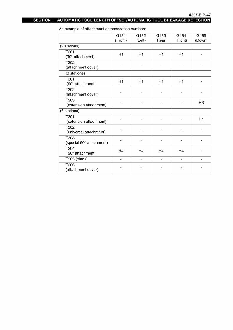
4297-E P-47SECTION 1 AUTOMATIC TOOL LENGTH OFFSET/AUTOMATIC TOOL BREAKAGE DETECTION
An example of attachment compensation numbers
G181(Front)
G182 (Left)
G183(Rear)
G184(Right)
G185 (Down)
(2 stations)
T301 (90° attachment)
H1 H1 H1 H1 -
T302 (attachment cover)
- - - - -
(3 stations)
T301 (90° attachment)
H1 H1 H1 H1 -
T302(attachment cover)
- - - - -
T303 (extension attachment)
- - - - H3
(6 stations)
T301 (extension attachment)
- - - - H1
T302 (universal attachment)
- - - - -
T303(special 90° attachment)
- - - - -
T304 (90° attachment)
H4 H4 H4 H4 -
T305 (blank) - - - - -
T306 (attachment cover)
- - - - -

4297-E P-48SECTION 1 AUTOMATIC TOOL LENGTH OFFSET/AUTOMATIC TOOL BREAKAGE DETECTION
3-2-9. Calculating the Compensation Data for a 90° Attachment
Eeoemr5s1052When a 90° attachment is used, it is necessary to find the attachment swivel compensation datausing the coordinate values obtained in step 5) of [3-2-8. Measuring the Attachment Swivel Com-pensation Data].The formula below are used to match the center of the vertical reference tool with the horizontal ref-erence tool nose.
EIOEMR5S1033R01
In the explanation below, D1 represents the diameter of the reference tool mounted in the verticalspindle and D2 the diameter of the reference tool mounted in the horizontal spindle.
• PAC = 0°
EIOEMR5S1034R01
• PAC = 90°
EIOEMR5S1035R01
• PAC = 180°
EIOEMR5S1036R01
Vertical reference tool
Horizontal reference tool
Vertical reference tool
D1 D2
Z+
Horizontal reference toolX+
X’ = X +
Y’ = Y
Z’ = Z +D2
2
D1
2
Vertical reference tool
Z+
Y+
Horizontal reference tool
X’ = X
Y’ = Y + D1
2
Z’ = Z + D2
2
X+Z+
Y’ = Y
D1
2X’ = X +
Z’ = Z + D2
2

4297-E P-49SECTION 1 AUTOMATIC TOOL LENGTH OFFSET/AUTOMATIC TOOL BREAKAGE DETECTION
• PAC = 270°
EIOEMR5S1037R01
Z+Y+Y’ = Y +
D1
2
X’ = X
Z’ = Z + D2
2
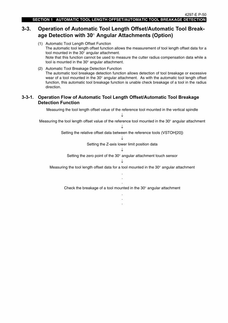
4297-E P-50SECTION 1 AUTOMATIC TOOL LENGTH OFFSET/AUTOMATIC TOOL BREAKAGE DETECTION
3-3. Operation of Automatic Tool Length Offset/Automatic Tool Break-age Detection with 30° Angular Attachments (Option)
Eeoemr5s1053(1) Automatic Tool Length Offset FunctionThe automatic tool length offset function allows the measurement of tool length offset data for atool mounted in the 30° angular attachment.Note that this function cannot be used to measure the cutter radius compensation data while atool is mounted in the 30° angular attachment.
(2) Automatic Tool Breakage Detection FunctionThe automatic tool breakage detection function allows detection of tool breakage or excessivewear of a tool mounted in the 30° angular attachment. As with the automatic tool length offsetfunction, this automatic tool breakage function is unable check breakage of a tool in the radiusdirection.
3-3-1. Operation Flow of Automatic Tool Length Offset/Automatic Tool Breakage Detection Function
Eeoemr5s1056Measuring the tool length offset value of the reference tool mounted in the vertical spindle
↓Measuring the tool length offset value of the reference tool mounted in the 30° angular attachment
↓Setting the relative offset data between the reference tools (VSTOH[20])
↓Setting the Z-axis lower limit position data
↓Setting the zero point of the 30° angular attachment touch sensor
↓Measuring the tool length offset data for a tool mounted in the 30° angular attachment
.
.
.
Check the breakage of a tool mounted in the 30° angular attachment
.
.
.

4297-E P-51SECTION 1 AUTOMATIC TOOL LENGTH OFFSET/AUTOMATIC TOOL BREAKAGE DETECTION
3-3-2. Relative Offset Data between Reference Tools (VSTOH [20])
Eeoemr5s1057To use the automatic tool length offset/automatic tool breakage detection function with an angularattachment other than a 90° angular attachment(30°, 45°, 60°), a special referent tool, called refer-ence tool B, is used to measure the attachment compensation data. Differing from the convention-ally used reference tool - called reference tool A - which has a cylindrical shape, reference tool Bhas a ball-shaped nose.When setting the touch sensor zero point, the sensor zero point in the vertical and horizontal direc-tions is usually determined by the length of reference tool A, which is determined by the specificationcode (Bit 7 of specification code No. 24).When setting the angular attachment touch sensor zero point, however, reference tool B is used toset the zero point. This means the accurate length of the reference tool must be known beforehand.The value used to calculate the length of reference tool B based on the length of reference tool A iscalled the “relative offset data between reference tools”.If a value is set for PLI, explained in [3-3-5. Setting the Touch Sensor Zero Point], setting the "relativeoffset data between reference tools" is not necessary.The relative offset data between reference tools can be obtained easily by following the procedureindicated below.
Procedure :
1 Mount reference tool B in the vertical spindle and read the Z-axis coordinate value by bringingit into contact with the reference block.Assume the read Z-axis coordinate value to be “B”.
2 Mount reference tool A in the vertical spindle and read the Z-axis coordinate value by bringingit into contact with the reference block.Assume the read Z-axis coordinate value to be “A”.
3 Calculate the relative offset data between reference tools using the following formula.
EIOEMR5S1038R01
Relative offset data between reference tools = Length of reference tool B (coordinate value B)
- Length of reference tool A (coordinate value A)

4297-E P-52SECTION 1 AUTOMATIC TOOL LENGTH OFFSET/AUTOMATIC TOOL BREAKAGE DETECTION
3-3-3. Designating the Operation Mode (VFST)
Eeoemr5s1058Use system variable “VFST” to designate the basic operation modes for automatic tool length offsetor automatic tool breakage detection operation for a 30° angular attachment.VFST consists of one byte (8 bits) and each bit has the following significance.
EIOEMR5S1039R01
NOTICE
Bit No. Setting Description
Bit 00 Automatic tool breakage detection cycle
1 Automatic tool length offset cycle
Bit 1 0 Always set “0”.
Bit 2 0 Always set “0”.
Bit 30
Moves the X-axis when positioning a reference tool at the touch sensor position.If this setting is made although the zero point of the touch sensor and the X-axis has not been set, this will cause very dangerous situation since positioning is made to the machine zero point in this case.
1Does not move the X-axis when positioning a reference tool at the touch sensor position.
Bit 4 0 Always set “0”.
Bit 5 0 Always set “0”.
Bit 6 0 Always set “0”.
Bit 70 Designates the relative offset type.
1 Designates the absolute offset type.
Pay attention to the setting of system variable VFST since it is also used for the automatic toollength offset/automatic tool breakage detection functions for a vertical tool, B/C-axis attachment,extension attachment and 90° angular attachment.Although the operation mode is backed up in the CNC memory, you are recommended to set themode for each execution of the automatic tool length offset/automatic tool breakage detectionfunctions since the setting is also used for other applications as described above.
VFST Bit 7 Bit 6 Bit 5 Bit 4 Bit 3 Bit 2 Bit 1 Bit 0

4297-E P-53SECTION 1 AUTOMATIC TOOL LENGTH OFFSET/AUTOMATIC TOOL BREAKAGE DETECTION
3-3-4. Setting the Z-axis Lower Limit Position (OO32)
Eeoemr5s1059When the automatic tool length offset/automatic tool breakage detection cycle is executed, a toolmust be brought into contact with the touch sensor at the right angle. Therefore, the tool is posi-tioned in the direction in which the touch sensor is at the right angle before executing these cycleswith the 30° angular attachment tool. The point where the tool is positioned is called the “approachstart position”.The position where the Y-axis should be retracted to avoid interference with a workpiece before posi-tioning to the approach start position is called the Z-axis lower limit position.For details on the approach start position, refer to [3-3-5. Setting the Touch Sensor Zero Point].The Z-axis lower limit position is also used as the spindle retraction position for sensor unit advance/retract operation for models such as MCR-B II in which the sensor unit can interfere with the spindleduring sensor unit advance/retract operation.Note that the set Z-axis lower limit position is used for the automatic tool length offset/automatic toolbreakage detection function of the MCM horizontal tool and the B/C-axis attachment and 90° angu-lar attachment. Therefore, if these specifications are used in combination, set the Z-axis lower limitposition with care.
Procedure :
1 Move the Y-axis to the position where the Z-axis lower limit position is to be set.In this operation, the Z- and X-axis may be at any position.
2 At this position, execute the following program after selecting the MDI or automatic mode.CALLOO32When this program is executed, the axes do not move.After the execution of the program, the actual position of the Z-axis is stored in system workcoordinate system No. 9 as the Z-axis lower limit position.The set value can be checked by opening the MSB ZERO OFFSET (VSZO✽[N]) pop-up win-dow on the GAUGING RESULTS screen.

4297-E P-54SECTION 1 AUTOMATIC TOOL LENGTH OFFSET/AUTOMATIC TOOL BREAKAGE DETECTION
3-3-5. Setting the Touch Sensor Zero Point
Eeoemr5s1060Before executing the automatic tool length offset/automatic tool breakage detection function usingthe 30° angular attachment, it is necessary to set the zero point of the touch sensor.Follow the procedure indicated below to set the touch sensor zero point.
Procedure :
1 Set the VFST (operation mode) in the MDI or automatic mode.For this operation, only bit 7 (incremental/absolute offset type selection) has significance. Forother bits “0” may be set.
2 Execute M144 (sensor unit advance) in the MDI or automatic mode.Pay attention to the execution of M144 since the sensor unit may interfere with the spindle onsome models.
3 Mount reference tool B to the 30° angular attachment and orient the attachment.
4 Position the tool approximately 10 mm away from the touch sensor so that it will contact thetouch sensor at the right angle when it is moved in the tool length direction.
5 Select the MDI or automatic mode and execute the following program.CALL OO34 PAXI=#07HAfter the execution of the program above, the touch sensor zero point coordinate values (X, Y,Z) are set using the designation for PAXI.For details of PAXI designation, refer to [3-3-11. Variables].Note the relative offset data between the reference tools (VSTOH[20]) is used since PLI is notdesignated.
NOTICE
For details on the relative offset data between the reference tools, refer to [3-3-2. Relative OffsetData between Reference Tools (VSTOH [20])].How the reference tool moves during the execution of the program is explained in [3-3-6. ReferenceTool Movements during Touch Sensor Zero Point Setting].The result is fed back as the zero point data to system work coordinate system No. 13.The set zero point data can be checked by opening the MSB ZERO OFFSET (VSZO✽[N]) pop-upwindow on the GAUGING RESULTS screen.
If PLI is designated, the value to be transferred differs depending on the tool length offset type(VFST setting). For the absolute offset type, set the length of reference tool B from the gauge lineto PLI. In the case of the relative offset type, set the relative length of reference tool B in refer-ence to reference tool A.

4297-E P-55SECTION 1 AUTOMATIC TOOL LENGTH OFFSET/AUTOMATIC TOOL BREAKAGE DETECTION
3-3-6. Reference Tool Movements during Touch Sensor Zero Point Setting
Eeoemr5s1061During the execution of the touch sensor zero point setting for a 30° angular attachment, the refer-ence tool moves as indicated below.
Machine operation(1) The reference tool moves to the approach start point (Y- and Z-axis).
The approach start point is calculated on a line extended from the 30° angular attachment touchsensor in the tool length direction. The following two positions are calculated on the extendedline: the position where the Z-axis is at the travel limit in the positive direction and the positionwhere the Y-axis is at the lower end limit position of the Z-axis. Of these two positions, the posi-tion that is closer to the touch sensor is taken as the approach start point.Since the sensor position has not been measured at the start of touch sensor zero point setting,the position 10 mm ahead of the point where the tool was moved in step 4) of the operationdescribed in [3-3-5. Setting the Touch Sensor Zero Point] is regarded as the 30° angular attach-ment touch sensor position.
(2) The spindle is oriented.
(3) The reference tool moves the Z-axis lower limit position (Y-axis).
(4) The sensor unit retracts.
(5) The sensor unit advances.
(6) The reference tool moves to the approach start point (Y-axis).
(7) The reference tool is brought into contact with the sensor (Z- and Y-axis).
(8) The reference tool moves to the approach start point (Z- and Y-axis).
(9) The reference tool retracts to the Z-axis lower limit position (Y-axis). (If PRET ≠ 1)
(10) The sensor unit retracts. (If PRET ≠ 1)This completes the setting of the touch sensor zero point.

4297-E P-56SECTION 1 AUTOMATIC TOOL LENGTH OFFSET/AUTOMATIC TOOL BREAKAGE DETECTION
3-3-7. Automatic Tool Length Offset Function
Eeoemr5s1062To measure the tool length of the tool mounted in the 30° angular attachment, follow the procedureindicated below.
NOTICE
Procedure :
1 Set the VFST (operation mode) in the MDI or automatic mode.For this operation, only the following bits have significance. For other bits “0” may be set.
• Bit 7 (incremental/absolute offset type selection)Set the same value as set in the touch sensor zero point setting operation.
• Bit 3 (X-axis positioning valid/invalid)“0” (X-axis positioning valid) may be set only when PAXI was used to set the zero point inthe touch sensor zero point setting operation.If “0” is set although the X-axis zero point has not been set, it could be dangerous sincethe X-axis is positioned to the machine zero point.
• Bit 0 (automatic tool length offset/automatic tool breakage detection selection)Since the operation to be performed is “automatic tool length offset”, “1” should be sethere.
2 Mount the tool for which automatic tool length offset is to be executed in the 30° angular attach-ment and set the angular attachment direction.If the tool is mounted manually, the PH parameter must be specified since the tool number isunknown.The obtained offset data is set as the tool length offset data of the tool number transferred bythe PH parameter.The PH parameter does not have to be designated if the tool is mounted using an M code com-mand.
3 Execute the following program after selecting the MDI or automatic mode.CALL OO34 (PLI=Anticipated tool length) (PH=Tool number)When the program is executed, the tool length is measured.The measured tool length data is set as the tool length offset data of the tool number trans-ferred by PH. If no PH parameter is specified, the data is set as the tool length offset data ofthe active tool number.
NOTICE
Before executing automatic tool length offset, make sure that the zero point of the touch sensorhas been set.
If an anticipated tool length is not set, the minimum tool length is used as the anticipated toollength.Therefore, the minimum tool length must be set beforehand for optional parameter (long word)No. 43, as an absolute value in mm units.If the setting for this parameter is inappropriate, the 30° angular attachment may interfere with thesensor unit. Set a value 10 mm longer than the minimum measurable length (determined by themachine specification) as the minimum tool length. If the minimum measurable length is set as the minimum tool length, the 30° angular attachmentwill strike the sensor unit if the tool fails to contact the sensor.
4297-E P-57SECTION 1 AUTOMATIC TOOL LENGTH OFFSET/AUTOMATIC TOOL BREAKAGE DETECTION
Machine operationDuring the execution of automatic tool length offset for the tool mounted in the 30° angular attach-ment, the tool moves as indicated below.
(1) The Z-axis moves up 1 mm from the actual position or to the travel end in the positive (+) direc-tion.If positioning of the X-axis is valid, X-axis positioning is executed.
(2) The spindle is oriented.
(3) The tool retracts to the Z-axis lower limit position (Y-axis).
(4) The sensor unit advances.
(5) The tool moves to the approach start point (Z-, Y-axis).If the maximum tool length designation is valid, it moves to the set maximum tool length position(Z-, Y-axis).
(6) The tool is brought into contact with the touch sensor (Z-, Y-axis).
(7) The tool moves to the approach start point (Z-, Y-axis).
(8) The tool retracts to the Z-axis lower limit position (Y-axis). (If PRET ≠ 1)
(9) The sensor unit retracts. (If PRET ≠ 1)
3-3-8. Tool Change Position Setting Function
Eeoemr5s1064When the automatic tool breakage detection cycle detects a tool has been broken, the broken toolcan be automatically returned to the magazine by using a subprogram.When a tool is returned to the magazine, it may interfere with a workpiece, depending on the shapeof the workpiece. To avoid this, it is necessary to retract the workpiece. The tool change positionsetting function is used to set the tool change position for this purpose.The spindle is moved to the tool change position by X- and Y-axis movements. Note that whether ornot the X-axis moves is determined by the setting for bit 3 of VFST. The X-axis moves only when “0”is set for this bit.
Procedure :
1 Move the spindle to the desired tool change position on the Y-axis.If the setting that enables X-axis movements is made, move the X-axis also.
2 Execute the following program after selecting the MDI or automatic mode.CALL OO31The axes will not move at all even when a program is executed.After the execution of the program, the actual position is set for system work coordinate systemNo. 2 as the tool change position.The set tool change position data can be checked by opening the MSB ZERO OFFSET(VSZO✽[N]) pop-up window on the GAUGING RESULTS screen.

4297-E P-58SECTION 1 AUTOMATIC TOOL LENGTH OFFSET/AUTOMATIC TOOL BREAKAGE DETECTION
3-3-9. Automatic Tool Breakage Detection
Eeoemr5s1065Automatic tool breakage detection is executed in the manner indicated below for the tool mounted inthe 30° angular attachment.
NOTICE
Procedure :
1 Set the VFST (operation mode) in the MDI or automatic mode.For this operation, only the following bits have significance. For other bits “0” may be set.
• Bit 7 (incremental/absolute offset type selection)Set the same value as set in the touch sensor zero point setting operation.
• Bit 3 (X-axis positioning valid/invalid)“0” (X-axis positioning valid) may be set only when PAXI was used to set the zero point inthe touch sensor zero point setting operation.If “0” is set although the X-axis zero point has not been set, it could be dangerous sincethe X-axis is positioned to the machine zero point.
• Bit 0 (automatic tool length offset/automatic tool breakage detection selection)Since the operation to be performed is “automatic tool length offset”, “1” should be sethere.
2 Mount the tool for which automatic tool length offset is to be executed in the 30° angular attach-ment and set the angular attachment direction.If the tool is mounted manually, the PH parameter must be specified since the tool number isunknown.The function compares the measured data to the tool length offset data of the tool offset num-ber transferred by PH to judge breakage of the tool.The PH parameter does not have to be designated if the tool is mounted using an M code com-mand.
3 Execute the following program after selecting the MDI or automatic mode.
EIOEMR5S1040R01
• Tool breakage judgment value (PLE1)If no value is set for PLE1, the judgment value is taken to be 0.1 mm.The tool is judged to be broken if the absolute value of the difference between the presettool length and the measured tool length is larger than the judgment value set for PLE1.
• Offset value update permissible amount (PLE2)When a value is set for PLE2, the present tool length offset data is updated to the mea-sured tool length assuming that the absolute value of the difference between the presettool length and the measured tool length is smaller than the judgment value set for PLE1and larger than the offset value update permissible amount.
• Processing on occurrence of tool breakage (PGO)If a tool is detected to have been broken while no value is set for PGO, an alarm occursand the tool breakage detection cycle ends without returning the broken tool to the mag-azine.
Before executing automatic tool breakage detection, make sure that the zero point of the touchsensor has been set.
CALL OO34 (PLE1=Tool breakage judgement value) (PLE2=Offset value update permissible amount)(PGO=Processing at the occurrence of tool breakage)

4297-E P-59SECTION 1 AUTOMATIC TOOL LENGTH OFFSET/AUTOMATIC TOOL BREAKAGE DETECTION
If a value is set for PGO to select the processing on occurrence of tool breakage, thespecified processing is executed without generating an alarm when tool breakage isdetected.PGO = 1: The tool is returned to the magazine without movement to the tool changeposition.PGO = 2: The tool is returned after positioning to the tool change position.PGO = 3: The tool is not returned to the magazine.Since no alarm occurs if a value is set for PGO, it is necessary to judge tool breakage ina program.For details on judgment of tool breakage in a program, refer to [3-3-10. Judgment forTool Breakage].
Machine OperationDuring the execution of the automatic tool breakage detection for the tool mounted in the 30° angu-lar attachment, the tool moves as indicated below.
(1) The Z-axis moves up 1 mm from the actual position or to the travel end in the positive (+) direc-tion.
If positioning of the X-axis is valid, X-axis positioning is executed.
(2) The spindle is oriented.
(3) The tool retracts to the Z-axis lower limit position (Y-axis).
(4) The sensor unit advances.
(5) The tool moves to the approach start point (Z-, Y-axis).If the maximum tool length designation is valid, it moves to the set maximum tool length position
(Z-, Y-axis).
(6) The tool is brought into contact with the touch sensor (Z-, Y-axis).
(7) The tool is assessed for breakage.
(8) The tool moves to the approach start point (Z-, Y-axis).
(9) The tool retracts to the Z-axis lower limit position (Y-axis). (If PRET ≠ 1)
(10) The sensor unit retracts. (If PRET ≠ 1)
The processing after the detection of tool breakage depends on the setting for PGO.
• PGO = 1:The tool is returned to the magazine without movement to the tool change position.
• PGO = 2:The tool is returned after positioning of the X- and Y-axis to the tool change position.

4297-E P-60SECTION 1 AUTOMATIC TOOL LENGTH OFFSET/AUTOMATIC TOOL BREAKAGE DETECTION
3-3-10. Judgment for Tool Breakage
Eeoemr5s1067When a spare tool is selected on detection of tool breakage, the machine is not stopped by an alarmeven if the breakage of a tool is detected. Therefore, it is necessary to judge whether or not a tool isbroken at the end of the automatic tool breakage detection cycle and branch a part program accord-ing to the result of the judgment.
• System variable VOK1VOK1 = 1: The tool is not broken.VOK1 ≠ 0: The tool is broken.System variable VOK1 stores the result of the tool breakage detection cycle executed immedi-ately before its designation.
• System variable VOK2System variable VOK2 is also used for storing the result of the tool breakage detection cycle.Differing from system variable VOK1, it indicates the occurrence of tool breakage in all detec-tion cycles executed after it has been reset to 0 (VOK2 = 0). If tool breakage is detected evenonce in these cycles, the value of VOK2 is not 0 (VOK2 ≠ 0).
• VOK1 and VOK2 are not reset by resetting the CNC.
[Supplement]The tool number of the tool which has been judged to be broken in a tool breakage detection cycleis registered as a broken tool by the tool management function.To use the same tool number after replacing the broken tool with a new one, it is necessary to resetthe registered broken tool status.For the procedure for resetting this status, refer to Tool Management Function in the special speci-fications of the Operation Manual.

4297-E P-61SECTION 1 AUTOMATIC TOOL LENGTH OFFSET/AUTOMATIC TOOL BREAKAGE DETECTION
3-3-11. Variables
Eeoemr5s1069Variables used in the subroutines that execute automatic tool length offset/automatic tool breakagedetection for the 30° angular attachment.
EIOEMR5S1041R01
PH: Tool offset numberUsed to designate a tool offset number if a tool offset number different from the tool num-ber of the active tool is used for automatic tool length offset/automatic tool breakage detection.
PAXI: One byte (8 bits) transfer variable used when the sensor zero point is set. Each bit has the following meaning.
Bit No. Description
Bit 0 Sets the X-axis zero point.
Bit 1 Sets the Y-axis zero point.
Bit 2 Sets the Z-axis zero point.
Bit 3 Always set “0”.
Bit 4 Always set “0”.
Bit 5 Always set “0”.
Bit 6 Always set “0”.
Bit 7 Always set “0”.
VFST: Designates the operation mode. For details refer to [3-3-3. Designating the Operation Mode (VFST)].
PLE1: Designates the tool breakage judgment value. For details refer to [3-3-9. Automatic Tool Breakage Detection].
PLE2: Designates the offset value update permissible amount. For details, refer to [3-3-9. Auto-matic Tool Breakage Detection].
PLI: Designates the length of the reference tool when setting the touch sensor zero point.Designates the anticipated tool length when measuring the tool length.
PRS: This is an RS command for multi-point spindle orientation operation.
PRET: Touch sensor retraction preventive commandThis is a function to prevent touch sensor retraction at the end of the touch sensor zero point setting, automatic tool length offset and automatic tool breakage detection.
PGO: Designates the processing to be followed on detection of tool breakage. For details, refer to [3-3-9. Automatic Tool Breakage Detection].
PX: Designates the displacement in the X-axis direction during positioning to the sensor posi-tion.
PAXI Bit 7 Bit 6 Bit 5 Bit 4 Bit 3 Bit 2 Bit 1 Bit 0

4297-E P-62SECTION 1 AUTOMATIC TOOL LENGTH OFFSET/AUTOMATIC TOOL BREAKAGE DETECTION
4. Y-axis Escape Position (MCM-B/MCR-B II/MCR-A/VH-40)Eeoemr5s1070During execution of automatic tool length offset (cutter radius compensation) or tool breakage detec-
tion on the vertical or horizontal spindle of MCM-B/MCR-B II/MCR-A, the tool may interfere with thetouch sensor unit cover.With VH-40, execution of automatic tool length offset or tool breakage detection may also causeinterference between the table and the touch sensor unit.In order to prevent such interference, the Y-axis escape cycle should be executed after setting the Y-axis escape position.
4-1. Setting the Y-axis Escape PositionEeoemr5s1071Setting the Y-axis Escape Position for the Vertical Spindle
Set the Y-axis escape position for the vertical spindle (includes VH-40) by following the procedureindicated below.
Procedure :
1 Move the Y-axis to the desired Y-axis escape position.In this operation, the X- and Z-axis may be at any position.
2 At this position, execute the following program after selecting the automatic mode.CALL OO33M02When this program is executed, the axes do not move.After the execution of the program, the actual position of the Y-axis is stored in system workcoordinate system No. 12 as the Y-axis escape position.The set value can be checked by opening the MSB ZERO OFFSET (VSZO✽[N]) pop-up win-dow on the GAUGING RESULTS screen.
Setting the Y-axis Escape Position for the Horizontal Spindle
Set the Y-axis escape position for the vertical spindle by following the procedure indicated below.
Procedure :
1 Move the Y-axis to the desired Y-axis escape position.In this operation, the X- and Z-axis may be at any position.
2 At this position, execute the following program after selecting the automatic mode.ALL OO32M02When this program is executed, the axes do not move.After the execution of the program, the actual position of the Y-axis is stored in system workcoordinate system No. 9 as the Y-axis escape position.The set value can be checked by opening the MSB ZERO OFFSET (VSZO✽[N]) pop-up win-dow on the GAUGING RESULTS screen.
[Supplement]Since system work coordinate systems No. 9 and No. 12 are used exclusively for automatic toollength offset (cutter radius compensation) and automatic tool breakage detection functions, theycannot normally be set or referenced.

4297-E P-63SECTION 1 AUTOMATIC TOOL LENGTH OFFSET/AUTOMATIC TOOL BREAKAGE DETECTION
CAUTION
4-2. Tool Movements during Automatic Tool Length Offset (Cutter Radius Compensation)/Automatic Tool Breakage Detection Cycle
Eeoemr5s1073During automatic tool length offset (cutter radius compensation)/automatic tool breakage detection,the tool moves as indicated below.
Machine operation in the case of vertical machining center (including VH-40)(1) The Z-axis moves at a rapid feedrate to the travel end in the positive (+) direction.
(2) The Y-axis moves at a rapid feedrate to the Y-axis escape position (the position set at systemwork coordinate system No. 9).
(3) The spindle is oriented.
(4) If the movable type sensor is used, the sensor moves back* once and then moves forward.* The sensor unit does not move back if it is already at the retract end position.
(5) The X- and Y-axis move at a rapid feedrate to align the tool nose with the center of the touchsensor.
(6) The tool is brought into contact with the touch sensor according to the selected cycle (automatictool length offset (cutter radius compensation)/automatic tool breakage detection cycle).
(7) The Z-axis moves at a rapid feedrate to the travel end in the positive (+) direction.
(8) The Y-axis moves at a rapid feedrate to the Y-axis escape position (the position set at systemwork coordinate system No. 12).
(9) If the movable type sensor is used, the sensor moves back.
[Supplement]
Machine operation in the case of horizontal machining center(1) The Z-axis moves at a rapid feedrate to the travel end in the positive (+) direction.
(2) The Y-axis moves at a rapid feedrate to the Y-axis escape position (the position set at systemwork coordinate system No. 9).
(3) The spindle is oriented.
(4) If the movable type sensor is used, the sensor moves back* once and then moves forward.* The sensor unit does not move back if it is already at the retract end position.
(5) The X- and Y-axis move at a rapid feedrate to align the tool nose with the center of the touchsensor.
(6) The tool is brought into contact with the touch sensor according to the selected cycle (automatictool length offset (cutter radius compensation)/automatic tool breakage detection cycle).
(7) The Z-axis moves at a rapid feedrate to the travel end in the positive (+) direction.
(8) The Y-axis moves at a rapid feedrate to the Y-axis escape position (the position set at systemwork coordinate system No. 9).
(9) If the movable type sensor is used, the sensor moves back.
Set the Y-axis escape position at a position where interference between the tool and the touchsensor unit cover will not occur.
With the VH-40, since the touch sensor zero point in the Y-axis direction is set at the same positionas the Y-axis escape position, only the X-axis moves in step 5).

4297-E P-64SECTION 1 AUTOMATIC TOOL LENGTH OFFSET/AUTOMATIC TOOL BREAKAGE DETECTION
5. Interference Prevention Measures for MCV-A/MCV-A II During Execution of the Automatic Tool Length Offset/Automatic Tool Breakage Detection Cycle
Eeoemr5s1075This function prevents interference between the touch sensor and the coolant trough, and betweenthe spindle tool and the chip cover, during the execution of the automatic tool length offset (cutterradius compensation)/automatic tool breakage detection cycle for the MCV-A/MCV-A II.To make this function valid, set “1” for CNC optional parameter (bit) No. 36, bit 4.
5-1. Touch Sensor Operation InterlockEeoemr5s1076A notch is provided in the coolant trough and the touch sensor zero point is set above the notch to
prevent interference of the coolant trough with the touch sensor.Touch sensor advance is enabled only at the touch sensor zero point. If the M144 command (touchsensor advance) is executed although the X-axis is not at the touch sensor zero point, the touchsensor does not move and the following alarm occurs.The touch sensor can be advanced only through the notched part. 2437 Alarm B Improper M code 5The X-axis touch sensor zero point described here is the position set by touch sensor zero point set-ting in the Z-axis direction and means the X-axis coordinate value in the system work coordinatesystem No. 1.
5-2. Measures against Interference during Execution of the Automatic Tool Length Offset/Tool Breakage Detection Cycle
Eeoemr5s1077In order to avoid interference between the tool and the chip cover, the X-axis touch sensor zero pointmust be set at the center of the notch provided in the chip cover so that the tool crosses the chipcover through that point.
5-2-1. Provisional Setting of the X-axis Touch Sensor Zero PointEeoemr5s1078Since the M144 command (touch sensor advance) is invalid unless the X-axis is located at the touch
sensor zero point, the provisional X-axis zero point must be set before setting the X-axis touch sen-sor zero point.Note that this setting is not necessary when adjusting a touch sensor zero point that has alreadybeen set.
Procedure :
1 Move the X-axis by manual operation to align the touch sensor with the center of the notch inthe coolant trough.
2 Select the MDI mode and execute “VFST=✽✽”.For "✽✽" set an appropriate value by referring to [6-3. How to Use Variables]. Here, the opera-tion mode may be either automatic tool length offset or automatic tool breakage detection.
3 Select the MDI mode and execute “VSZOX[1]=VRCOX-VMOFX”.
4 Execute M144.
[Supplement]Set the touch sensor zero point in the Z direction by designating “PAXI=7”.
4297-E P-65SECTION 1 AUTOMATIC TOOL LENGTH OFFSET/AUTOMATIC TOOL BREAKAGE DETECTION
5-2-2. Automatic Tool Length Offset/Automatic Tool Breakage Detection
Eeoemr5s1080Before executing the automatic tool length offset or tool breakage detection cycle, set “0” for bit 3 ofVFST to enable X-axis movement.VFST setting for the execution of the automatic tool length offset or automatic tool breakage detec-tion cycle
• Relative offsetAutomatic tool length offset: 1Automatic tool breakage detection: 0
• Absolute offsetAutomatic tool length offset: #81HAutomatic tool breakage detection: #80H
This instruction manual specifies that the tool moves to the touch sensor position during the execu-tion of an automatic tool length offset or tool breakage detection cycle in the following sequence:Z-axis upper limit → Y-axis touch sensor position → X-axis touch sensor position. In this order of tool movements, however, the tool will interfere with the chip cover. The setting indicated above changes the order to: Z-axis upper limit → Z-axis touch sensor position → Y-axis touch sensor position.Similarly, if “PGO = 2” is designated, the order of tool movements to the tool change position (theposition set by the execution of OO31), where the tool moves after the detection of tool breakage, ischanged to:Z-axis upper limit → Y-axis tool change position → X-axis tool change position.

4297-E P-66SECTION 1 AUTOMATIC TOOL LENGTH OFFSET/AUTOMATIC TOOL BREAKAGE DETECTION
6. Variables Used in SubprogramsEeoemr5s1081The basic command format of the automatic tool length offset function and the automatic tool break-
age detection function was explained in the previous subsections.In this subsection, the variables necessary to make effective use of these functions are described.
6-1. Table of Subprograms and VariablesEeoemr5s1082
Subpro-gram Name
Variables for which a Numeri-cal Value Must be Set
Variables for which a Numeri-cal Value Should be Set as
Needed
Variable which Must
not be Used
Setting of Z-axis touch sensor zero point
OO30 PAXI:=3 =4
=7
VFST:
Setting of X- and Y-axis zero pointsSetting of Z-axis zero pointSetting of X-, Y- and Z-axis zero pointsOperation mode
PLI:
PRS:
PRET:=1PH:
PD:
Accurate tool length of reference tool used in setting the zero pointSpindle orientation angleSensor does not retract.Tool length offset numberCutter radius com-pensation number
None
Setting of Y-axis touch sensor zero point
OO30 PAXI:=#17H
VFST:PLI:
PY:
Setting of X-, Y- and Z-axis zero pointsOperation modeAccurate tool length of reference tool used in setting the zero pointAccurate cutter radius of reference tool used in setting the zero point
PRS:
PRET:=1
PH:
PD:
Spindle orientation angle
Sensor does not retract.Tool length offset numberCutter radius com-pensation number
None
Setting of tool change position(Not necessary for MC-H)
OO31 None None None

4297-E P-67SECTION 1 AUTOMATIC TOOL LENGTH OFFSET/AUTOMATIC TOOL BREAKAGE DETECTION
Automatic tool length offset
OO30 VFST:PY:
Operation modeApproximate dis-placement of tool nose in the Y-axis direction from the center of the spindle (i.e., cutter radius)Always set when executing Y-axis automatic tool offset
PLI:
PX:
PY:
PFA:
PF1:
PF2:
PRS:
PRET:=1
PH:
PD:
Anticipated tool lengthApproximate dis-placement of tool nose in the X-axis direction from the center of the spin-dle+/- values are possible.Approximate dis-placement of tool nose in the Y-axis direction from the center of the spindleFeedrate for the movement from the sensor to undertravel point, PUDT (safety distance)Skip feedrate for the first contact detec-tion cycleSkip feedrate for the second contact detection cycleSpindle orientation angle
Sensor does not retract.Tool length offset numberCutter radius com-pensation number
PAXI
Subpro-gram Name
Variables for which a Numeri-cal Value Must be Set
Variables for which a Numeri-cal Value Should be Set as
Needed
Variable which Must
not be Used

4297-E P-68SECTION 1 AUTOMATIC TOOL LENGTH OFFSET/AUTOMATIC TOOL BREAKAGE DETECTION
Automatic tool breakage detection
OO30 VFST:PY:
Operation modeApproximate dis-placement of the tool nose in the Y-axis direction from the center of the spindle (i.e., cutter radius)Always set when executing Y-axis automatic tool break-age detection
PX:
PY:
PLE1:
PLEY:
PLE2:
PGO:
PRS:
PRET:=1
PH:
PD:
PFA:
PF1:
PF2:
Approximate dis-placement of the tool nose in the X-axis direction from the center of the spindle +/- values are possi-ble.Approximate dis-placement of the tool nose in the Y-axis direction from the center of the spindle +/- values are possi-ble.Z-axis direction tool breakage judgment valueY-axis direction tool breakage judgment valueOffset value update permissible amountProcessing on occurrence of tool breakageSpindle orientation angle
Sensor does not retract.Tool length offset numberCutter radius com-pensation numberFeedrate for the movement from the sensor to the under-travel point, PUDT (safety distance)Skip feedrate for the first contact detec-tion cycleSkip feedrate for the second contact detection cycle
PAXI
Subpro-gram Name
Variables for which a Numeri-cal Value Must be Set
Variables for which a Numeri-cal Value Should be Set as
Needed
Variable which Must
not be Used

4297-E P-69SECTION 1 AUTOMATIC TOOL LENGTH OFFSET/AUTOMATIC TOOL BREAKAGE DETECTION
6-2. Table of Subprograms and Variables (MCM Horizontal Tools)Eeoemr5s1083
Subpro-gram Name
Variables for which a Numeri-cal Value Must be Set
Variables for which a Numeri-cal Value Should be Set as
Needed
Variable which Must
not be Used
Setting of tool length direction touch sensor zero point(Y-axis)
OO30 PAXI:=#23H
=#24H
=#27H
VFST:
Setting of X- and Y-axis zero pointsSetting of Z-axis zero pointSetting of X-, Y- and Z-axis zero pointsOperation mode
PLI:
PRS:
PRET:=1
PH:
PD:
Accurate tool length of reference tool used in setting the zero pointSpindle orientation angle
Sensor does not retract.Tool length offset numberCutter radius com-pensation number
None
Setting of tool radius direction touch sensor zero point(Z-axis)
OO30 PAXI=#47H
VFST:PLI:
PZ:
Setting of X-, Y- and Z-axis zero pointsOperation modeAccurate tool length of reference tool used in setting the zero pointAccurate cutter radius of reference tool used in setting the zero point
PRS:
PRET:=1
PH:
PD:
Spindle orientation angle
Sensor does not retract.Tool length offset numberCutter radius com-pensation number
None
Z-axis lower limit setting
OO32 None None None

4297-E P-70SECTION 1 AUTOMATIC TOOL LENGTH OFFSET/AUTOMATIC TOOL BREAKAGE DETECTION
Automatic tool length offset
OO30 VFST:PZ:
Operation modeApproximate dis-placement of tool nose in the tool radius direction (Z-axis direction)Always set when executing automatic tool length offset in the tool radius direc-tion
PLI:
PX:
PZ:
PFA:
PF1:
PF2:
PRS:
PRET:=1
PH:
PD:
Anticipated tool lengthApproximate dis-placement of tool nose in the X-axis direction from the center of the spindleApproximate dis-placement of tool nose in the Z-axis direction from the center of the spindleFeedrate for the movement from the sensor to the under-travel point, PUDT (safety distance)Skip feedrate for the first contact detec-tion cycleSkip feedrate for the second contact detection cycleSpindle orientation angle
Sensor does not retract.Tool length offset numberCutter radius com-pensation number
PAXI
Subpro-gram Name
Variables for which a Numeri-cal Value Must be Set
Variables for which a Numeri-cal Value Should be Set as
Needed
Variable which Must
not be Used

4297-E P-71SECTION 1 AUTOMATIC TOOL LENGTH OFFSET/AUTOMATIC TOOL BREAKAGE DETECTION
Automatic tool breakage detection
OO30 VFST:PZ:
Operation modeApproximate dis-placement of tool nose in the tool radius direction (Z-axis direction)Always set when executing automatic tool length offset in the tool radius direc-tion
PX:
PZ:
PLE1:
PLEZ:
PLE2:
PGO:
PRS:
PRET:=1
PH:
PD:
PFA:
PF1:
PF2:
Approximate dis-placement of tool nose in the X-axis direction from the center of the spindleApproximate dis-placement of tool nose in the Z-axis direction from the center of the spindleTool length direction (Y-axis direction) tool breakage judgment valueTool radius direction (Z-axis direction) tool breakage judgment valueOffset value update permissible amountProcessing on occurrence of tool breakageSpindle orientation angle
Sensor does not retract.Tool length offset numberCutter radius com-pensation numberFeedrate for the movement from the sensor to the under-travel point, PUDT (safety distance)Skip feedrate for the first contact detec-tion cycleSkip feedrate for the second contact detection cycle
PAXI
Subpro-gram Name
Variables for which a Numeri-cal Value Must be Set
Variables for which a Numeri-cal Value Should be Set as
Needed
Variable which Must
not be Used
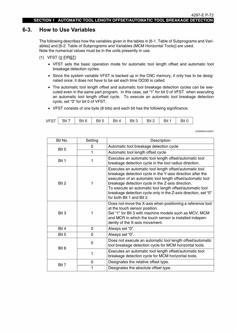
4297-E P-72SECTION 1 AUTOMATIC TOOL LENGTH OFFSET/AUTOMATIC TOOL BREAKAGE DETECTION
6-3. How to Use VariablesEeoemr5s1084The following describes how the variables given in the tables in [6-1. Table of Subprograms and Vari-
ables] and [6-2. Table of Subprograms and Variables (MCM Horizontal Tools)] are used.Note the numerical values must be in the units presently in use.
(1) VFST (V FIRST)
• VFST sets the basic operation mode for automatic tool length offset and automatic toolbreakage detection cycles.
• Since the system variable VFST is backed up in the CNC memory, it only has to be desig-nated once: it does not have to be set each time OO30 is called.
• The automatic tool length offset and automatic tool breakage detection cycles can be exe-cuted even in the same part program. In this case, set “1” for bit 0 of VFST when executingan automatic tool length offset cycle. To execute an automatic tool breakage detectioncycle, set “0” for bit 0 of VFST.
• VFST consists of one byte (8 bits) and each bit has the following significance.
EIOEMR5S1042R01
Bit No. Setting Description
Bit 00 Automatic tool breakage detection cycle
1 Automatic tool length offset cycle
Bit 1 1Executes an automatic tool length offset/automatic tool breakage detection cycle in the tool radius direction.
Bit 2 1
Executes an automatic tool length offset/automatic tool breakage detection cycle in the Y-axis direction after the execution of an automatic tool length offset/automatic tool breakage detection cycle in the Z-axis direction.To execute an automatic tool length offset/automatic tool breakage detection cycle only in the Z-axis direction, set “0” for both Bit 1 and Bit 2.
Bit 3 1
Does not move the X-axis when positioning a reference tool at the touch sensor position.Set “1” for Bit 3 with machine models such as MCV, MCM and MCR in which the touch sensor is installed indepen-dently of the X-axis movement.
Bit 4 0 Always set “0”.
Bit 5 0 Always set “0”.
Bit 60
Does not execute an automatic tool length offset/automatic tool breakage detection cycle for MCM horizontal tools.
1Executes an automatic tool length offset/automatic tool breakage detection cycle for MCM horizontal tools.
Bit 70 Designates the relative offset type.
1 Designates the absolute offset type.
VFST Bit 7 Bit 6 Bit 5 Bit 4 Bit 3 Bit 2 Bit 1 Bit 0
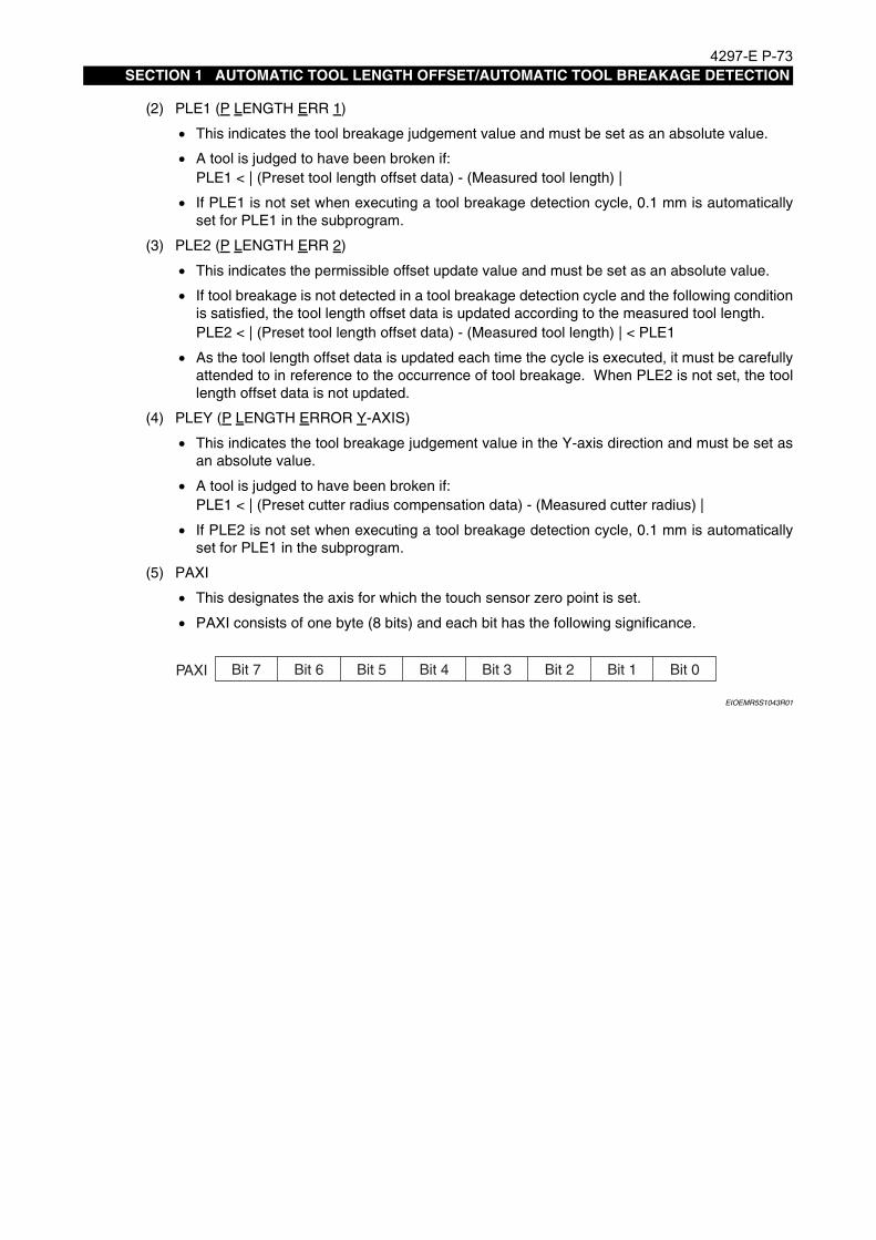
4297-E P-73SECTION 1 AUTOMATIC TOOL LENGTH OFFSET/AUTOMATIC TOOL BREAKAGE DETECTION
(2) PLE1 (P LENGTH ERR 1)
• This indicates the tool breakage judgement value and must be set as an absolute value.
• A tool is judged to have been broken if:PLE1 < | (Preset tool length offset data) - (Measured tool length) |
• If PLE1 is not set when executing a tool breakage detection cycle, 0.1 mm is automaticallyset for PLE1 in the subprogram.
(3) PLE2 (P LENGTH ERR 2)
• This indicates the permissible offset update value and must be set as an absolute value.
• If tool breakage is not detected in a tool breakage detection cycle and the following conditionis satisfied, the tool length offset data is updated according to the measured tool length.PLE2 < | (Preset tool length offset data) - (Measured tool length) | < PLE1
• As the tool length offset data is updated each time the cycle is executed, it must be carefullyattended to in reference to the occurrence of tool breakage. When PLE2 is not set, the toollength offset data is not updated.
(4) PLEY (P LENGTH ERROR Y-AXIS)
• This indicates the tool breakage judgement value in the Y-axis direction and must be set asan absolute value.
• A tool is judged to have been broken if:PLE1 < | (Preset cutter radius compensation data) - (Measured cutter radius) |
• If PLE2 is not set when executing a tool breakage detection cycle, 0.1 mm is automaticallyset for PLE1 in the subprogram.
(5) PAXI
• This designates the axis for which the touch sensor zero point is set.
• PAXI consists of one byte (8 bits) and each bit has the following significance.
EIOEMR5S1043R01
PAXI Bit 7 Bit 6 Bit 5 Bit 4 Bit 3 Bit 2 Bit 1 Bit 0

4297-E P-74SECTION 1 AUTOMATIC TOOL LENGTH OFFSET/AUTOMATIC TOOL BREAKAGE DETECTION
Setting value of PAXI
(6) PX
• This indicates an approximate displacement of the tool nose from the center of the tool(spindle) in the X-axis direction. Designation of plus and minus values is possible. When PXis not set, “PX = 0” is automatically set in a subprogram.
• When the X- and Y-axis move to the center of the touch sensor during automatic tool lengthoffset/automatic tool breakage detection cycle, the tool is positioned PX away from the cen-ter of the touch sensor so that the tool nose is aligned with the center of the touch sensor.
• Since the touch sensor is installed close to the travel limit, pay attention to the setting of PXin reference to the travel limit.
(7) PYThis indicates an approximate displacement of the tool nose from the center of the tool (spindle)in the Y-axis direction. For other details, refer to the explanation for “PX”.When setting the Y-axis zero point, an accurate cutter radius (displacement of the tool nose inthe Y-axis direction) of the reference tool used for zero point setting must be set for PY.
Bit No. Description
Bit 0 Sets the X-axis zero point.
Bit 1 Sets the Y-axis zero point.
Bit 2 Sets the Z-axis zero point.
Bit 3 Always set “0”.
Bit 4
0: Sets the zero point of the tool length direction touch sensor for a vertical tool.1: Sets the zero point of the tool radius direction touch sensor for a vertical tool.
Bit 5Sets the zero point of the tool length direction touch sensor for a horizontal tool.
Bit 6Sets the zero point of the tool radius direction touch sensor for a horizontal tool.
Bit 7 Always set “0”.
Axis Name
Sensor Direction
Vertical Tool MCM Horizontal Tool
Length Direc-tion Sensor
Radius Direc-tion Sensor
Length Direc-tion Sensor
Radius Direc-tion Sensor
Setting of X- and Y-axis zero points
3 (#13H) #23H (#43H)
Setting of Z-axis zero point 4 (#14H) #24H (#44H)
Setting of X-, Y- and Z-axis zero points
7 #17H #27H #47H
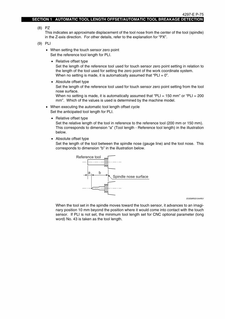
4297-E P-75SECTION 1 AUTOMATIC TOOL LENGTH OFFSET/AUTOMATIC TOOL BREAKAGE DETECTION
(8) PZThis indicates an approximate displacement of the tool nose from the center of the tool (spindle)in the Z-axis direction. For other details, refer to the explanation for “PX”.
(9) PLI
• When setting the touch sensor zero pointSet the reference tool length for PLI.
• Relative offset typeSet the length of the reference tool used for touch sensor zero point setting in relation tothe length of the tool used for setting the zero point of the work coordinate system.When no setting is made, it is automatically assumed that “PLI = 0”.
• Absolute offset typeSet the length of the reference tool used for touch sensor zero point setting from the toolnose surface.When no setting is made, it is automatically assumed that “PLI = 150 mm” or “PLI = 200mm”. Which of the values is used is determined by the machine model.
• When executing the automatic tool length offset cycleSet the anticipated tool length for PLI.
• Relative offset typeSet the relative length of the tool in reference to the reference tool (200 mm or 150 mm).This corresponds to dimension “a” (Tool length - Reference tool length) in the illustrationbelow.
• Absolute offset typeSet the length of the tool between the spindle nose (gauge line) and the tool nose. Thiscorresponds to dimension “b” in the illustration below.
EIOEMR5S1044R01
When the tool set in the spindle moves toward the touch sensor, it advances to an imagi-nary position 10 mm beyond the position where it would come into contact with the touchsensor. If PLI is not set, the minimum tool length set for CNC optional parameter (longword) No. 43 is taken as the tool length.
Reference tool
Spindle nose surfacea b

4297-E P-76SECTION 1 AUTOMATIC TOOL LENGTH OFFSET/AUTOMATIC TOOL BREAKAGE DETECTION
(10) PFA/PF1/PF2These designate the approach or skip feedrate for tool movements toward the sensor.
• PFA: Feedrate for the movement from the sensor to the undertravel point, PUDT (safety dis-tance)
• PF1: Skip feedrate for the first contact detection cycle
• PF2: Skip feedrate for the second contact detection cycle
(11) PGO(P GO)This determines the processing to be followed after the detection of tool breakage. Selection ispossible from “alarm-stop” and “spare tool selection”.
• When PGO is not set:When a tool breakage is detected during the automatic tool breakage detection cycle, theCNC stops in the alarm state after the completion of the automatic tool breakage detectioncycle.
• When the setting is “PGO = 1”:When a tool breakage is detected during the automatic tool breakage detection cycle, thebroken tool is returned to the magazine after the automatic tool breakage detection cycle iscompleted. Then, the execution part program is continued.With MC-V and double-column machining centers, the tool change cycle is executed at theX, Y coordinate positions where the cycle has been executed; therefore, do not set “PGO =1” for these models.
PFA without PLI(anticipated tool length)
Override valid
• When PFA command is not designated:F=PF1 (automatic tool length offset)F4000 (automatic tool breakage detection)
• When PFA command is designated:F=PF1 (automatic tool length offset)F=PFA (automatic tool breakage detection)
PFA with PLI(anticipated tool length)
Override valid
• When PFA command is not designated:F=PF1 (automatic tool length offset)F4000 (automatic tool breakage detection)
• When PFA command is designated:F=PFA
Skip feedrate for the first contact detection cycle
Override valid
• When PF1 command is not designated:F2000
• When PF1 command is designated:F=PF1
Skip feedrate for the second contact detection cycle
Override invalid
• When PF2 command is not designated:F1000
• When PF1 command is designated:F=PF2

4297-E P-77SECTION 1 AUTOMATIC TOOL LENGTH OFFSET/AUTOMATIC TOOL BREAKAGE DETECTION
• When the setting is “PGO = 2”:This setting is not allowed for MC-H.With MC-H, do not set PGO as “2”.If tool breakage is detected during the automatic tool breakage detection cycle, the X- and Y-axis move to the preset tool change position (Y-axis moves first and then the X-axis) after thecompletion of the tool breakage detection cycle. Then, the broken tool is returned to themagazine and the execution of the part program is continued.The tool change position must be set beforehand by executing the tool change position set-ting cycle.
• When the setting is “PGO = 3”:Even when tool breakage is detected during the automatic tool breakage detection cycle, thepart program is executed continuously after the automatic tool breakage detection cycle.
If the setting for PGO is “1”, “2” or “3”, regardless of whether or not the broken tool isreturned to the magazine, the CNC does not stop even if tool breakage is detected and apart program continues to be executed after the completion of the tool breakage detectioncycle.Therefore, it is necessary to judge if the tool is broken or not in a part program and follow thenecessary processing if a tool is found to have been broken. The result of the tool breakage detection cycle is set for system variable VOK1.VOK1 = 1: Tool has not been broken.VOK1 ≠ 1: Tool has been broken.If a measurement impossible alarm occurs, whatever setting is made for PGO, the CNC isalarm-stopped after the automatic tool breakage cycle is completed.
CAUTION1) Setting “PGO = 1” is not allowed with MC-V and double-column machining centers. This
setting can cause interference between the tool or the tool change arm and the work-piece if a tool change cycle starts after an automatic tool breakage detection cycle.
2) Setting “PGO = 2” is not allowed for MC-H. This setting can cause interference betweenthe tool or the spindle and the workpiece in Y- or X-axis movement that follows an auto-matic tool breakage detection cycle.

4297-E P-78SECTION 1 AUTOMATIC TOOL LENGTH OFFSET/AUTOMATIC TOOL BREAKAGE DETECTION
(12) PRS (P RS)When using a special tool, a boring bar for example, the tool bit can fail to contact the touchsensor if the spindle is orient stopped at the preset position. In such cases, it is necessary toindex the spindle to the desired angular position. PRS is used to set the desired spindle indexangle for such cases.Example:In the case of the tool shown below, set “270” for PRS to index the spindle to allow toolbit to contact the touch sensor.
EIOEMR5S1045R01
Execute “CALL OO30 PRS = 270”
EIOEMR5S1046R01
[Supplement]
(13) PRET (P RETRACT)With the retract type touch sensor, the sensor retracts after the completion of a cycle. If “1” isset for this variable, the cycle completes with the sensor at the advanced position.
(14) PH/PD
• Offset data (tool length offset data, cutter radius compensation data) are usually set and ref-erenced for the offset number identical to the actual tool number. By setting PH and/or PD,the offset data can be set for the desired offset number.PH: Tool length offset number (default: actual tool number)PD: Cutter radius compensation number (default: PH number)
• Setting range: 1 to The number of tool data sets
[Supplement]
Spindle orientation is automatically executed at the travel end of the Z-axis in the positivedirection.
Even when only cutter radius compensation is executed, it is necessary to set both PH and PDsince the tool length offset data is also referenced.
Tool
Y-
Sensor
Y+
Y-Y+

4297-E P-79SECTION 1 AUTOMATIC TOOL LENGTH OFFSET/AUTOMATIC TOOL BREAKAGE DETECTION
(15) VLTL (Maximum tool length)The maximum tool length VLTL, used for the automatic tool offset and automatic tool breakagedetection cycles, is added to the system parameters. The operational step 4) in Fig. 1-1 CycleTime Reduction Function on page 28 becomes valid according to the setting for this parameter:
• Optional parameter (bit) No. 36, bit 31: Valid0: Invalid (initial setting)
• Optional parameter (long ward) No. 44: Max. tool length dataFor the maximum tool length, set the maximum tool length among the tools that will be used.Setting range: 0 to 999Unit: mmInitial setting: 0 (may be changed)
CAUTION
(16) PUDT (Undertravel distance (Safety clearance))When a tool is moved towards the sensor, its feedrate is switched from a high speed to a lowspeed. The position where the feedrate is switched is set for this variable in terms of the dis-tance from the sensor to the tool nose. See Fig. 1-1 Cycle Time Reduction Function onpage 28.Designate this variable when calling the subprogram.If PUDT is not set, the following value is regarded as the undertravel distance.
• Automatic tool length offset cycleBoth PLI and PFA are designated: 50 mmEither PLI or PFA is not designated: 10 mm
• Automatic tool breakage detection cycleUndertravel distance: 5 mm
(17) POVT (Overtravel distance (Sensor damaging prevention distance))This is provided to prevent breakage of the sensor if the sensor fails to function when the toolcontacts it.Set the distance from the assumed sensor contact position to the position where axis feedshould stop if the sensor fails to operate.Designate this variable when calling the subprogram. If POVT is not set, “10 mm” is automati-cally set for it.
Because the initial setting for the maximum tool length is “0”, an appropriate value must beset for VLTL.

4297-E P-80SECTION 1 AUTOMATIC TOOL LENGTH OFFSET/AUTOMATIC TOOL BREAKAGE DETECTION
7. Cautions on OperationEeoemr5s1085(1) Because the sensor will not work properly if its zero point is not set, be sure to set the sensor
zero point by executing the sensor zero point setting cycle when the machine is installed. ForMCM, the zero point setting cycle must be executed for the horizontal spindle touch sensor.
• The sensor zero point is set for system work coordinate system No. 1 (Z-axis sensor) andsystem work coordinate system No. 4 (Y-axis sensor).
• System work coordinate systems No. 1 and No. 4 are exclusive to automating specificationsand can neither be set by parameter setting nor referenced.
• System work coordinate systems No. 1 and No. 4 can only be checked by displaying theMSB ZERO OFFSET (VSZO✽[N]) pop-up window in the GAUGING RESULT display screen.
(2) When setting “PGO = 2” with MC-V or a double-column machining center, make sure that thetool change position setting cycle has been executed.The tool change position for the automatic tool breakage detection cycle is set for system workcoordinate system No. 2. System work coordinate system No. 2 is exclusive to automatingspecifications and can neither be set by parameter setting nor referenced.
(3) An emergency stop limit switch is built into the system to protect the touch sensors. This limitswitch stops axis movement if a sensor is pushed in too far.If this happens, the emergency stop limit indicating lamp in the control panel lights up. Torelease the emergency stop condition, select the manual mode, set the emergency stop limitrelease switch to valid, and retract the sensor by moving the axis with the pulse handle in thedirection in which the limit switch is released.
(4) Do not call out the automatic tool length offset or automatic tool breakage detection subprogramwhile there is a remaining shift amount in manual interruption operation or while the machine isstill in the mirror image mode. If a subprogram call is attempted, a “measuring impossible”alarm occurs.
(5) As the automatic tool length offset and automatic tool breakage detection functions are used incombination with the tool management function, the operator must become fully acquaintedwith the tool management function by reading its manual thoroughly before using these func-tions.
(6) The explanations in this manual relate to tools that have the cutting nose at the front edge, suchas drills, taps and reamers. For tools whose cutting edge is off the center of the spindle, likeboring bars, variables PRS and PX or PY must be set in accordance with the tool nose offsetdirection.
(7) The automatic tool length offset and automatic tool breakage detection functions cannot beused for tools whose tool holder comes into contact with the touch sensor or touch sensor unitbefore the tool nose does.
(8) Numerical values must be assigned to subprograms in the presently used unit system.Note that the real number unit system must not be used.
(9) The cutter radius compensation mode and the local coordinate system are cancelled when anautomatic tool length offset or automatic tool breakage detection subprogram is executed and,once cancelled, they are not restored after the completion of the subprogram.
(10) Call automatic tool length offset and automatic tool breakage detection subprograms in a workcoordinate system. An alarm occurs if a subprogram is called in the machine coordinate sys-tem. Note that a work coordinate system cannot be altered during the execution of an automatictool length offset or automatic tool breakage detection subprogram.
(11) Do not use the user area as the area for storing programs, work coordinate systems, tool offsetdata and common variables, automatic tool length offset or automatic tool breakage detectionsubprograms.

4297-E P-81SECTION 1 AUTOMATIC TOOL LENGTH OFFSET/AUTOMATIC TOOL BREAKAGE DETECTION
(12) The allowable number of nesting levels of subroutines in an automatic tool length offset or toolbreakage detection subprogram is two. This means that the maximum allowable nesting level issix when these functions are executed.
(13) Manual advance/retraction operation of the tool breakage detection unit (touch sensor)With MCM and MCR, the touch sensor can be manually moved forwards and backwards.
a) Set the CNC operation panel mode selecting key-lock type switch to ON to enable indepen-dent manual operation.
b) Set the selector switch to FORWARDS.
c) Press the CYCLE START button.The cover will open and the touch sensor will move forward when the CYCLE START buttonis released.
d) Set the selector switch to BACKWARDS.
e) Press the CYCLE START button.The touch sensor will move backward and the cover will close when the CYCLE START but-ton is released.
f) Set the CNC operation panel mode selecting key-lock type switch to OFF to disable inde-pendent manual operation.
(14) An alarm usually occurs if the actual tool number is “0” when a tool length offset or cutter radiuscompensation cycle is executed. Therefore, you are recommended to carry out a tool change inthe MDl or automatic mode in this case.

4297-E P-82SECTION 1 AUTOMATIC TOOL LENGTH OFFSET/AUTOMATIC TOOL BREAKAGE DETECTION
8. Program Examples
8-1. Automatic Tool Length OffsetEeoemr5s1086• Relative offset type
EIOEMR5S1047R01
EIOEMR5S1048R01
Boring barDrill
T6T2
PY=30
N1 T2
N2 M6
N3 T6
N4 CALL OO30VFST=1(PLI=40)(PF1=1000) .............Tool length offset cycle for T2
N5 M6 PLI ................................................................... Anticipated tool length (relative length)
in reference to the standard tool N6 T5 PF1 ...................................................................First approach feedrate
N7 CALL OO30 PY=30................................................ Tool length offset cycle for T6
N8 M6 PY.....................................................................Tool nose offset amount from the
spindle center (Y direction) = 30 mm
:
:

4297-E P-83SECTION 1 AUTOMATIC TOOL LENGTH OFFSET/AUTOMATIC TOOL BREAKAGE DETECTION
• Absolute offset type
EIOEMR5S1049R01
Commands in ( ) may be omitted.It is not necessary to set variable VFST every time a tool length offset cycle is called. As has beenexplained, the touch sensor zero point must be set before the execution of an automatic tool lengthoffset cycle. For the setting of the touch sensor zero point, select the same offset type (relative orabsolute) as the type used for the automatic tool length offset cycle.
N1 T2
N2 M6
N3 T6
N4 CALL OO30 VFST=#81H (PLI=240) (PF1=1500) ...... Tool length offset cycle for T2
N5 M6 PL1 ........................................................................ Anticipated tool length
(absolute length)
N6 T5
N7 CALL OO30 PY=30 ......................................................Tool length offset cycle for T6
N8 M6
:
:

4297-E P-84SECTION 1 AUTOMATIC TOOL LENGTH OFFSET/AUTOMATIC TOOL BREAKAGE DETECTION
8-2. Automatic Tool Breakage DetectionEeoemr5s1087• Alarm stop
EIOEMR5S1050R01
EIOEMR5S1051R01
Commands in ( ) may be omitted.
Boring bar
PY=30
T3
N1 T1 ..............................T1: Drill
N2 M6
N3 T3 ..............................T3: Boring bar
N4 S300
N5 G81 G56 X40 Y20 Z-30 R3 F80 H1
:
:
:
N12 CALL OO30 VFST=0 (PLE1=0.2)*1 (PLE2=0.05) .. Tool breakage detection cycle for T1
N13 M6
N14 T2 PLE1 ................................................................... Tool breakage judgment value
= 0.2 mm
N15 G0 X30 Y10 .............................................................. If no tool breakage judgment value is
set, "0.1 mm" is automatically set as
the tool breakage judgment value.
:
N29 CALL OO30 PY=30 (PLE1=0.1) ...............................Tool breakage detection cycle for T3
Off-center amount of tool nose:
30 mm
:
:
:

4297-E P-85SECTION 1 AUTOMATIC TOOL LENGTH OFFSET/AUTOMATIC TOOL BREAKAGE DETECTION
When the tool is judged “broken”, i.e., when the measured tool length is smaller than the set toolbreakage judgment value, the operation stops in an alarm state on completion of the cycle (Z-axispositioned at travel end in the positive direction).
• Automatic spare tool selection (MC-H)
EIOEMR5S1052R01
*1: Tool length offset data is updated when variable “PLE2” is set.When the tool length measured in the tool breakage detection cycle is 0.051 mm to 0.2 mm (the range set by “PLE1” and “PLE2”) shorter than the initial tool length measured in the auto-matic tool length offset cycle, the tool length offset data is automatically updated based on the tool length measured in the tool breakage detection cycle to compensate for the tool wear amount.When no “PLE2” data is set, the tool length offset data is not updated.
Boring bar
PY=30
T3T1
Drill

4297-E P-86SECTION 1 AUTOMATIC TOOL LENGTH OFFSET/AUTOMATIC TOOL BREAKAGE DETECTION
EIOEMR5S1053R01
It is not necessary to set variable VFST every time an automatic tool breakage detection cycle iscalled.
*: HA may be designated instead of H1. For details, refer to special specifications of the Operation Manual.
N1 T1 ..............................T1: Drill
N2 M6
N3 T3 ..............................T3: Boring bar
N4 G0 X40 Y10 S300
N5 G56 Z40 H1* M3
:
:
:
N18 CALL OO30 VFST=0 (PLE1=0.1) PGO=2 ...... Tool breakage detection cycle for T1 Tool
breakage judgment value
= 0.1 mm
N19 IF [VOK1 NE 0] N999 ..................................... Jump to N999 if tool is judged "broken"
VOK1: Judgment for tool breakage
N20 M6
N21 T9
N22 G0 X100 Y20
N23 G56 Z20 H3 :
:
:
N42 CALL OO30 PY=30 PGO=2 ........................... Tool breakage detection cycle for T3
N43 IF [VOK1 NE 0] N999 ...................................... Tool breakage judgment value
= 0.1 mm
Tool nose offset amount from the spindle
center = 30 mm
:
:
N999 M60 ............................................................... Pallet change command
Part program for the next workpiece ....................... If a broken tool is called in this program,
a spare tool is automatically selected
rom the same tool group.
At the same time as the spare tool is
selected, the tool offset data is rewritten to
the offset data of the selected spare tool.
The cutter radius compen sation data is
rewritten also.

4297-E P-87SECTION 1 AUTOMATIC TOOL LENGTH OFFSET/AUTOMATIC TOOL BREAKAGE DETECTION
9. Alarm ListEeoemr5s1088Name of Alarm Probable Cause Measures to Take
UNTENDED:gauging impossible(ALARM-B 2305)
At the end of the gauging impossible message, the cause code is displayed.
Refer to the Gauging Impossible Cause Code List and eliminate the cause.
UNTENDED:no subprogram function(ALARM-B 2311)
An attempt is made to execute the tool breakage detection cycle although the corresponding specification is not sup-ported.
Check the VFST setting.
UNTENDED:tool breakage(ALARM-B 2309)
Tool breakage is detected in the tool breakage detection cycle.
Direct of subscript(ALARM-B 2231)
Tool number is “0”.PH and/or PD setting is wrong.
When a tool is changed manually, the active tool number must be set.
UNTENDED:command missing(ALARM-B 2308)
• The PAT command value is out ofthe specifiable range (outside therange 1 to 7).
• Wrong PAC command
• The PAT command is not desig-nated although “1” is set for VFST,bit 6.
Plus travel limit over(ALARM-B 2268)
The value assigned to PLI is too large. Do not set a value larger than the maxi-mum measurable tool length for PLI.For the allowable maximum length of the tool to be measured, refer to your final machine/control specifications.
The value set for the zero point of the touch sensor is incorrect.The touch sensor zero point has been set in the relative offset type but mea-surement is executed in the absolute off-set type, or the touch sensor zero point has been set in the absolute offset type but measurement is executed in the rel-ative offset type.
Set the touch sensor zero point again. Be sure to use the same offset type (rel-ative/absolute) for the setting and mea-surement.
ALARM-B2305 UNTENDED: gauging impossible ××
↑Cause code

4297-E P-88SECTION 1 AUTOMATIC TOOL LENGTH OFFSET/AUTOMATIC TOOL BREAKAGE DETECTION
Gauging Impossible Cause Code List <Alarm B 2305>
Minus travel limit over(ALARM-B 2269)
The value set for CNC optional parame-ter (long word) No. 43 (measurable mini-mum tool length) is too small.
Do not set a value smaller than the mini-mum measurable tool length for CNC optional parameter (long word) No. 43.For the minimum allowable length of the tool to be measured, refer to your final machine/control specifications.
The value assigned to PLI is too small. Do not specify a value smaller than the minimum measurable tool length for PLI.For the maximum allowable length of the tool to be measured, refer to your final machine/control specifications.
The touch sensor zero point has been set in the relative offset type but mea-surement is executed in the absolute off-set type, or the touch sensor zero point has been set in the absolute offset type but measurement is executed in the rel-ative offset type.
Set the touch sensor zero point again. Be sure to use the same offset type (rel-ative/absolute) for the setting and mea-surement.
Code(HEX)
Probable Cause Measures to TakeUsed Subpro-
grams
1 A maker subprogram is called while the machine coordinate system (H0) is selected.
Call a maker subprogram after select-ing a work coordinate system (G15 H1, for example).
OO10OO30OO50
2 The mirror image function is active. Cancel the mirror image function first. OO10OO30OO50
3 Manual shift amount (total) remains. Cancel the manual shift amount (total) to zero.
OO10OO30OO50
4 In the G11 mode (parallel or rotation shift of a coordinate)
Cancel the G11 mode first. OO10
5 In the G51 mode (graphics enlarge-ment/reduction)
Cancel the G51 mode first. OO10
6 T number is zero (0), or no tool is set. • Specify a T number.
• Specify the PTLN command.
OO30
7 Specified T number or PTLN com-mand is larger than the maximum off-set number.
Specify a T number or PTLN com-mand within the allowable range.
OO30
8 The power to the probe is not on when the flash on cycle is attempted.
Check the following:
• Is there any obstacle between thereceiver head and the probe?
• Is the spindle index angle for theprobe correct?
• Does the receiver head flash?
OO15
9 The offset amount of the positioning point for cycle start from the touch sen-sor zero point is greater than PCHK (only for Y and Z axes).
When positioning the Y and Z axes, position them within the range of PCHK from the touch sensor zero point.
OO30
Name of Alarm Probable Cause Measures to Take

4297-E P-89SECTION 1 AUTOMATIC TOOL LENGTH OFFSET/AUTOMATIC TOOL BREAKAGE DETECTION
A The touch probe microcomputer stays on.
Check whether chips are accumulating on the proximity switch.
OO10
B The result of the touch probe test is NG.The touch probe signal cannot be con-firmed.
Check the touch probe battery. OO10
C The touch probe contacts the work-piece while it is being fed at a rapid approach feedrate (X-axis).
With the FM type touch probe, recep-tion of signals is not correct.
• Gauging cycle start point
• PUDT setting
OO10
D The touch probe fails to contact the workpiece while it is being fed at a middle approach feedrate (X-axis).
When using the FM type touch probe, signal reception is not correct.
• Gauging cycle start point
• POVT setting
OO10
E The touch probe fails to contact the workpiece while it is being fed at the final approach feedrate (X-axis).When using the FM type touch probe, signal reception is not correct.
Check the touch probe battery. OO10
F The proximity switch is not turned on although the touch probe is brought into contact with a workpiece (X-axis).
Check if the touch probe has chat-tered.
OO10
10 The touch probe contacts the work-piece while it is being fed at a rapid approach feedrate (Y-axis). When using the FM type touch probe, signal reception is not correct.
Check the following:
• Gauging cycle start point
• PUDT setting
OO10
11 The touch probe fails to contact the workpiece while it is being fed at a middle approach feedrate (Y-axis). When using the FM type touch probe, signal reception is not correct.
Check the following:
• Gauging cycle start point
• POVT setting
OO10
12 The touch probe fails to contact the workpiece while it is being fed at the final approach feedrate (Y-axis). When using the FM type touch probe, signal reception is not correct.
Check the touch probe battery. OO10
13 The proximity switch is not turned on although the touch probe is brought into contact with a workpiece (X-axis).
Check if the touch probe has chat-tered.
OO10
14 The touch probe contacts the work-piece while it is being fed at a rapid approach feedrate (Z-axis). When using the FM type touch probe, signal reception is not correct.
Check the following:
• Gauging cycle start point
• PUDT setting
OO10
Code(HEX)
Probable Cause Measures to TakeUsed Subpro-
grams

4297-E P-90SECTION 1 AUTOMATIC TOOL LENGTH OFFSET/AUTOMATIC TOOL BREAKAGE DETECTION
15 The touch probe fails to contact the workpiece while it is being fed at a middle approach feedrate (Z-axis). When using the FM type touch probe, signal reception is not correct.
Check the following:
• Gauging cycle start point
• POVT setting
OO10
16 The touch probe fails to contact the workpiece while it is being fed at the final approach feedrate (Z-axis). When using the FM type touch probe, signal reception is not correct.
Check the touch probe battery. OO10
17 The proximity switch is not turned on although the touch probe is brought into contact with a workpiece (Z-axis).
Check if the touch probe has chat-tered.
OO10
18 The touch probe contacts the work-piece during the approach to the exter-nal diameter in the OD gauging cycle.
Check the following items:
• Start point of the gauging cycle
• Assumed OD value
OO10
19 PLH is not designated. Set tool length offset number for PLH.
1A PDH is not designated. Set the cutter radius compensation number for PDH.
1B In the C-axis gauging cycle, contact is detected during the approach to the gauging point.
Check the following items:
• Is start point of the C-axis gaugingcycle correct?
• Is PDl value correct?
• Is PGI value correct?
OO10
1C Touch probe contact is not detected in X-axis direction motion within the range of PUDT and POVT. (contact value error)
OO100
1D Touch probe contact is not detected in Y-axis direction motion within the range of PUDT and POVT. (contact value error)
OO100
1E Touch probe contact is not detected in Z-axis direction motion within the range of PUDT and POVT. (contact value error)
OO100
1F In the touch sensor zero setting cycle for the vertical spindle longitudinal direction, the cutting tool fails to con-tact the sensor.
Check the start point of the cycle; is it close to the touch sensor (within 10 mm)?
OO30
20 In the touch sensor zero setting cycle for the vertical spindle radial direction, the cutting tool fails to contact the sen-sor.
Check the start point of the cycle; is it close to the touch sensor(within 10 mm)?
OO30
21 In the touch sensor zero setting cycle for horizontal spindle longitudinal direction, the cutting tool fails to con-tact the sensor.
Check the start position of the cycle; is it close to the touch sensor(within 10 mm)?
OO30
Code(HEX)
Probable Cause Measures to TakeUsed Subpro-
grams

4297-E P-91SECTION 1 AUTOMATIC TOOL LENGTH OFFSET/AUTOMATIC TOOL BREAKAGE DETECTION
22 In the automatic tool length offset/automatic tool breakage detection cycle for the horizontal spindle in the radial direction, the cutting tool fails to contact the sensor.
Check the start point of the cycle; is it close to the touch sensor (within 10 mm)?
OO30
23 When the axis moves 0.5 mm in the positive direction from the contact detect point, the probe contact signal has already been on. (X direction)
OO100
24 When the axis moves 0.5 mm in the positive direction from the contact detect point, the probe contact signal has already been on. (Y direction)
25 When the axis moves 0.5 mm in the positive direction from the contact detect point, the probe contact signal has already been on. (Z direction)
26 When the axis returns 0.5 mm from the contact position detected after approach (X direction), the value is taken as the coordinate value in the workpiece gauging direction again.
27 When the axis returns 0.5 mm from the contact position detected after approach (Y direction), the value is taken as the coordinate value in the workpiece gauging direction again.
28 When the axis returns 0.5 mm from the contact position detected after approach (Z direction), the value is taken as the coordinate value in the workpiece gauging direction again.
29 In the automatic tool length offset/automatic tool breakage detection cycle for the vertical spindle in the lon-gitudinal direction, the cutting tools fails to contact the sensor.
Check if the anticipated tool length is correct. (for tool length offset cycle)
OO30
2B In the automatic tool length offset/automatic tool breakage detection cycle for the horizontal spindle in the longitudinal direction, the cutting tool fails to contact the sensor.
Check the following items:
• Is the anticipated tool length cor-rect? (for tool length offset cycle)
• Is the cutter radius offset dataset? (for tool breakage detectioncycle)
OO30
2C In the automatic tool length offset/automatic tool breakage detection cycle for the vertical spindle in the radial direction, the cutting tool fails to contact the sensor.
Check the following items:
• Is the anticipated cutter radiuscorrect? (for tool length offsetcycle)
• Is the cutter radius offset dataset? (for tool breakage detectioncycle)
OO30
Code(HEX)
Probable Cause Measures to TakeUsed Subpro-
grams

4297-E P-92SECTION 1 AUTOMATIC TOOL LENGTH OFFSET/AUTOMATIC TOOL BREAKAGE DETECTION
2D In the automatic tool length offset cycle in the X-axis direction (with angular attachment), the cutting tool fails to contact the sensor.
Check if PL1 is appropriate. OO30
33 In the U-center zero setting cycle, the cutting bit contacts the sensor, or the contact signal is input, in a sequence in which the cutting bit should not con-tact the sensor.
Check the following items:
• Is the sensor zero point set cor-rectly?
• Is the cutting bit free of chips?
• Is the sensor signal correct?
34 In the U-center zero setting cycle, no contact signal is input.
Check the following items:
• Is PD value correct?
• Is the sensor signal correctly inputto the CNC?
35 In the U-center radius adjusting cycle, the cutting bit contacts the touch sen-sor while the Y-axis is being fed in a sequence in which contact must not be detected.
Check the following items:
• Is the command value correct?
• Is the sensor signal correctly inputto the CNC?
• Is the cutting bit free of chips?
36 In the U-center radius adjusting cycle, the cutting bit fails to contact the touch sensor.
Check the following items:
• Is the U-axis command too large?
• Is the sensor signal correctly inputto the CNC?
37 In the U-center radius adjusting cycle, the cutting bit fails to contact the touch sensor in the sequence in which the U-axis adjusted amount is checked on the Y-axis.
Check if the sensor signal is correctly input to the CNC.
38 In the tool breakage detection cycle, the cutting bit contacts the touch sen-sor while the Y-axis is being fed in a sequence in which contact must not be detected.
Check the following items:
• Is the sensor zero point set cor-rectly?
• Is the sensor signal correctly inputto the CNC?
• Is the cutting bit free of chips?
39 In the tool wear compensation cycle, the cutting bit contacts the touch sen-sor in a sequence in which the Y-axis positioning is executed to a point dis-tanced from the current position by the compensation amount.
Check the following items:
• Is the command value correct?
• Is the U-center bit free of chips?
• Is the sensor signal correctly inputto the CNC?
3A In the tool wear compensation cycle, the cutting bit fails to contact the touch sensor in a sequence in which the cut-ting bit radial position is corrected in the U-axis adjusting cycle.
Check if the sensor signal is correctly input to the CNC.
Code(HEX)
Probable Cause Measures to TakeUsed Subpro-
grams

4297-E P-93SECTION 1 AUTOMATIC TOOL LENGTH OFFSET/AUTOMATIC TOOL BREAKAGE DETECTION
3B After the completion of U-axis com-pensation in the tool wear compensa-tion cycle, the cutting bit fails to contact the touch sensor in the sequence in which the adjusted amount is checked in the Y-axis movement.
Check if the sensor signal is correctly input to the CNC.
3C When the gauging cycle is executed with a touch probe set in the vertical spindle of the MCM, swivel head is not in the M75 (rear) position.
Execute the gauging cycle after index-ing the swivel head to the M75 (rear) position.
OO10
3D In the touch sensor zero setting cycle for the vertical spindle in the longitudi-nal direction on the MCM, the swivel head is not in the M73 (front) position, or the horizontal spindle is being used.
• Execute the cycle after indexingthe swivel head to the M73 (front)position.
• Check if the PAXI data is correct.
OO30
3E In the touch sensor zero setting cycle for the vertical spindle in the radial direction on the MCM, the swivel head is not in the M73 (front) position, or the horizontal spindle is being used.
• Execute the cycle after indexingthe swivel head to the M73 (front)position.
• Check if the PAXI data is correct
OO30
3F In the touch sensor zero setting cycle for the horizontal spindle in the longitu-dinal direction on the MCM, the swivel head is not in the M76 (right) position, or the horizontal spindle is being used.
• Execute the cycle after indexingthe swivel head to the M76 (right)position.
• Check if the PAXI data is correct
OO30
40 In the touch sensor zero setting cycle for the horizontal spindle in the radial direction on the MCM, the swivel head is not in the M76 (right) position, or the horizontal spindle is being used.
• Execute the cycle after indexingthe swivel head to the M76 (right)position.
• Check if the PAXI data is correct.
OO30
41 The tool number for the angular attachment is T52 or T53. (For the angular attachment tool, only T51 (90° angular attachment) can be used for tool length offset).
Check if the T command is correct.
42 The power supply for the optical type touch probe cannot be turned on.
OO16OO18
43 The power supply for the optical type touch probe cannot be turned off.
OO17OO19
Code(HEX)
Probable Cause Measures to TakeUsed Subpro-
grams

4297-E P-94SECTION 2 AUTOMATIC GAUGING FUNCTION
SECTION 2 AUTOMATIC GAUGING FUNCTION
1. OverviewEeoemr5s2001The automatic gauging function automatically checks the dimensions of a workpiece by executing a
subprogram. The touch probe with the same shank shape as the cutting tool is mounted in the spin-dle and brought into contact with the gauging face of the workpiece to read the coordinate values ofthe contact point. The workpiece dimension is then automatically calculated using these coordinatevalues.The results of gauging are displayed on the screen. It is also possible to judge if the gauging resultis acceptable or not in a part program. A function to output the results of gauging to the printer isprovided as an option.It is possible to set the zero offset of any work coordinate system based on the results of gauging.The automatic gauging function is classified into the following two major function types.
• Dimension check function
• Automatic zero offset function (includes the dimension check function)
1-1. Dimension Check FunctionEeoemr5s2002The following four gauging patterns are provided for the dimension check function.
(1) Inner diameter (ID) gaugingThis function automatically measures the center position and the workpiece inner diameter.The results can be evaluated.
(2) Outer diameter (OD) gaugingThis function automatically measures the center position and the workpiece outer diameter.The results can be evaluated.
(3) End face gaugingThis function automatically measures the end face position in any of the following directions: X-axis, Y-axis and Z-axis directions.The results can be evaluated.
(4) Calculation of the center and distance between two pointsThis function calculates the center and the distance between two points measured in any of thethree patterns (1) to (3) described above.Since the results obtained from the gauging cycle (gauging results) are automatically comparedwith the theoretical values (anticipated values) and the difference calculated to judge whether ornot the gauging result is acceptable, this function can be used for the following purposes.
• Controlling the workpiece dimensions
• Recognizing the workpiece type (or pallet table)
• Confirming the zero point
1-2. Automatic Zero Offset FunctionEeoemr5s2003The automatic zero offset function offsets the zero point so that the coordinate values of the position
where the dimension check was executed will be the desired coordinate values. In this way, zero offset is possible for any required work coordinate system.

4297-E P-95SECTION 2 AUTOMATIC GAUGING FUNCTION
2. Operation of the Automatic Gauging FunctionEeoemr5s2004The following flowchart shows the operating procedure of the automatic gauging function.
EIOEMR5S2001R01
[Supplement]The explanation in this section assumes that the functions are executed in the automatic mode.Therefore, the programs necessary in each step of the operation must be prepared. Use the pro-gram edit function to prepare these programs.
Is the machine model MCM?
Is the touch probe mounted in the vertical spindle?
No
Yes
No
Yes
Setting the zero point of the datum hole
Checking the ON/OFF state of the touch probe
Executing the radius compen-sation for the touch probe
Executing the length offset for the touch probe
Checking the workpiece dimension
Automatic zero offset
Execute these steps once a week to maintain the accuracy of automatic gauging.In addition to this compensation/offset at regular intervals, you are recommended to execute these procedures when a new touch probe is set in the magazine.Zero point setting of the datum hole is necessary only when a touch probe is mounted in the vertical spindle (horizontal spindle for MC-H).
Execute this function for controlling workpiece dimensions, judging workpiece kinds or offsetting the zero point automatically.
Execute this function to automatically offset the zero point according to the results of the dimension check function.
4297-E P-96SECTION 2 AUTOMATIC GAUGING FUNCTION
2-1. Setting the Datum Hole Zero PointEeoemr5s2005The datum hole zero point needs to be set only when mounting a touch probe in the horizontal spin-
dle (in the case of MC-H) or the vertical spindle (in the case of MC-V).If a touch probe is mounted in the horizontal spindle of MCM, zero point setting must not be per-formed.
Procedure :
1 Mount a datum hole block (master ring) that has an accurately measured φ20 mm or largerdiameter hole in it.
2 Accurately align the datum hole center with the spindle center using sling gauge or similar tool.Use the pulse handle for this operation.
3 Set the zero point.
4 Select the MDI mode and execute positioning to the zero point at a rapid feedrate. At the zeropoint, check the measured value again.
5 Move only the Z-axis in the positive (+) direction to remove the sling gauge and mount thetouch probe in the spindle.
6 Move the Z-axis in the negative (-) direction to the position where the touch probe ball entersthe datum hole.
7 Move the Z-axis so that the touch probe ball enters the datum hole 5 to 7 mm from the datumblock upper face.
8 Select the MDI mode and execute the following program.CALL OO21M02When this program is executed, the zero point is set so that the actual position of the touchprobe will be X=0, Y=0, Z=0 of system work coordinate system No. 3.

4297-E P-97SECTION 2 AUTOMATIC GAUGING FUNCTION
The result of setting can be confirmed by opening the MSB ZERO OFFSET (VSZO✽[N]) pop-up window in the GAUGING RESULTS screen. The set X, Y and Z values are displayed at X,Y and Z columns of the NO. 3 line.
EIOEMR5S2002R01
[Supplement]
For the procedure for opening the MSB ZERO OFFSET (VSZO✽[N]) pop-up window, refer to SEC-TION 1 [1-2-2. MSB ZERO ON/OFF Function Key].
Since system work coordinate system No. 3 is used exclusively for the automatic gauging function,it cannot normally be set or referenced.

4297-E P-98SECTION 2 AUTOMATIC GAUGING FUNCTION
2-2. Touch Probe Radius CompensationEeoemr5s2006The following describes how the touch probe radius is corrected.
To maintain high gauging accuracy, touch probe radius compensation must be executed at leastonce a week.
2-2-1. Touch Probe Radius Compensation Operation
Eeoemr5s2007The general operating procedure for touch probe radius compensation is described below.For touch probe radius compensation for the MCM horizontal spindle, refer to [2-2-2. Touch ProbeRadius Compensation Operation (MCM Horizontal Spindle)].
CAUTION
Procedure :
1 Execute the datum hole zero point setting cycle.
2 In the MDI mode, specify “VNCOM[1] = 8” and touch the probe by hand to check if the contactdetection signal is correctly turned ON and OFF.The ON/OFF state of the contact detection signal can be checked by displaying the ACTUALPOSITION screen or by observing the indicator lamps on the operation panel.
3 Mount the touch probe in the spindle.
4 Select the automatic mode and execute the following program.CALL OO10 PMOD=9 PDI=(Datum hole diameter) POVT=3M02The command must be specified in the presently selected unit system.When the program is executed, the touch probe automatically enters the datum hole and theradius compensation cycle is executed.The results of the cycle are set for the tool radius compensation number indicated below.
If the radius compensation cycle for the touch probe is executed before setting the zero point ofthe datum hole, the machine will operate unpredictably.Execute the touch probe radius compensation cycle only after setting the datum hole zero point.
System VariableDirection
Radius Compensation Data
X+ VSTOD [1]
X- VSTOD [2]
Y+ VSTOD [3]
Y- VSTOD [4]
Z+ -
Z- VSTOD [5]

4297-E P-99SECTION 2 AUTOMATIC GAUGING FUNCTION
The set data can be checked by opening the MSB TOOL LENGTH OFFSET (VSTOH[N])/MSBCUTR COMP. (VSTOD[N]) pop-up window, shown below.
EIOEMR5S2003R01
For the procedure for opening the MSB TOOL ON/OFF pop-up window, refer to SECTION 1[1-2-3. MSB TOOL ON/OFF Function Key].After making sure that the touch probe radius compensation data is set for the tool radius com-pensation number, proceed to the steps below.
5 Using the hole where the touch probe radius compensation cycle has been executed, executethe ID gauging cycle.For the ID gauging cycle, refer to [2-4. Inner Diameter (ID) Gauging Function].
6 On the GAUGING RESULT display screen, compare the anticipated center value with the mea-sured center value to confirm that the difference is less than several micrometers.
7 Remove the touch probe from the spindle and mount the sling gauge instead.
8 Turn the sling gauge at the measured center position and compare the measured center value,sling gauge reading and anticipated center value. Make sure that differences among thesethree values are less than several micrometers.This completes the touch probe radius compensation operation.
[Supplement]Since cutter radius compensation numbers 1 to 20 for the system are used exclusively for the auto-matic gauging function, they cannot normally be set or referenced.

4297-E P-100SECTION 2 AUTOMATIC GAUGING FUNCTION
Machine operationDuring the execution of the touch probe radius compensation cycle, the touch probe moves as indi-cated below.
(1) The Z-axis moves at a rapid feedrate to the travel end in the positive (+) direction.
(2) The spindle is oriented.Spindle orientation may be executed after the spindle has rotated a half turn to check the touchprobe signal.For details, refer to [6-1. Checking Proximity Switch Operation].
(3) The X- and Y-axis move to the center of the datum hole at a rapid feedrate.
(4) The Z-axis moves down at a rapid feedrate until the touch probe ball reaches a point 30 mmaway from the datum hole.
(5) The Z-axis moves down 30 mm further at a rapid feedrate and the touch probe ball enters thedatum hole.
(6) Datum hole gauging cycle is executed in the following sequence: X+ direction, X- direction, Y+direction and Y- direction.
(7) The Z-axis moves at a rapid feedrate to the travel end in the positive (+) direction.
2-2-2. Touch Probe Radius Compensation Operation (MCM Horizontal Spindle)
Eeoemr5s2009The operating procedure for touch probe radius compensation is described below for the touchprobe mounted in the MCM horizontal spindle.For general touch probe radius compensation, refer to [2-3. Touch Probe Length Offset].
Procedure :
1 Mount a datum hole block (master ring) that has an accurately measured φ20 mm or largerdiameter hole in it.
2 Accurately align the datum hole center with the spindle center using sling gauge or similar tool.Use the pulse handle for this operation.
3 Set the zero point.To do this, select the zero point setting mode and enter the data using the keyboard.
4 Select the MDI mode and execute positioning to the zero point at a rapid feedrate. At the zeropoint, check the measured value again.
5 Move only the Z-axis in the positive (+) direction to remove the sling gauge, and mount thetouch probe in the spindle.At the POT NO./TOOL NO. TABLE (FIXED ADDRESS) in the TOOL DATE SET screen mode,set HORIZONTAL TOOL USED for ACTUAL TOOL NO.
6 Move the Z-axis in the negative (-) direction to the position where the touch probe ball entersthe datum hole.
7 Move the Z-axis so that the touch probe ball enters the datum hole 5 to 7 mm from the datumblock upper face.

4297-E P-101SECTION 2 AUTOMATIC GAUGING FUNCTION
8 In the MDI mode, specify “VNCOM[1] = 8” and touch the probe by hand to check if the contactdetection signal is correctly turned ON and OFF.The ON/OFF state of the contact detection signal can be checked by displaying the ACTUALPOSITION screen or by observing the indicator lamps on the operation panel.
9 Mount the touch probe in the spindle.
10 Select the automatic mode and execute the following program.CALL OO10 PMOD=9 PDI=(Datum hole diameter) POVT=3M02The command must be specified in the presently selected unit system.When the program is executed, the touch probe automatically enters the datum hole and theradius compensation cycle is executed.
[Supplement]
The results of the cycle are set for the tool radius compensation number indicated below.
The set data can be checked by opening the MSB TOOL LENGTH OFFSET (VSTOH[N])/MSBCUTR COMP. (VSTOD[N]) pop-up window, shown below.
EIOEMR5S2004R01
To allow the CNC to automatically recognize the direction of the touch probe, the touch probemust be mounted in the spindle in the automatic or MDI mode.
Radius Com-pensation Data
Direction
System Variable
M73 (Front) M74 (Left) M75 (Rear) M76 (Right)
X+ - VSTOD [9] VSTOH [3] VSTOD [17]
X- VSTOH [1] VSTOD [10] - VSTOD [18]
Y+ VSTOD [7] VSTOH [2] VSTOD [15] -
Y- VSTOD [8] - VSTOD [16] VSTOH [4]
Z+ VSTOD [5] VSTOD [11] VSTOD [13] VSTOD [19]
Z- VSTOD [6] VSTOD [12] VSTOD [14] VSTOD [20]

4297-E P-102SECTION 2 AUTOMATIC GAUGING FUNCTION
For the procedure for opening the MSB TOOL ON/OFF pop-up window, refer to SECTION 1 [1-2-3. MSB TOOL ON/OFF Function Key].After making sure that the touch probe radius compensation data is set for the tool radius com-pensation number, proceed to the steps below.
11 Using the hole where the touch probe radius compensation cycle has been executed, executethe ID gauging cycle.For the ID gauging cycle, refer to [2-4. Inner Diameter (ID) Gauging Function].
12 On the GAUGING RESULT display screen, compare the anticipated center value with the mea-sured center value to confirm that the difference is less than several micrometers.
13 Remove the touch probe from the spindle and mount the sling gauge instead.
14 Turn the sling gauge at the measured center position and compare the measured center value,sling gauge reading and anticipated center value. Make sure that differences among thesethree values are less than several micrometers.This completes the touch probe radius compensation operation for the touch probe mounted inthe MCM horizontal spindle.
[Supplement]
Machine operationDuring the execution of the touch probe radius compensation cycle for the touch probe mounted inthe MCM horizontal spindle, the touch probe moves as indicated below.
(1) The spindle is oriented.Spindle orientation may be executed after the spindle has rotated a half turn to check the touchprobe signal.For details, refer to [6-1. Checking Proximity Switch Operation].
(2) The gauging cycle is executed for the datum hole in the sequence indicated below.
(3) The Z-axis moves to and stops at the center of the datum hole.
Since cutter radius compensation numbers 1 to 20 for the system are used exclusively used for theautomatic gauging function, then cannot normally be set or referenced.
Touch Probe DirectionGauging Order
1 2 3 4
MCMHorizontal
spindle
M73 (Front) Y+ Y- Z+ Z-
M74 (Left) X+ X- Z+ Z-
M75 (Rear) Y+ Y- Z+ Z-
M76 (Right) X+ X- Z+ Z-

4297-E P-103SECTION 2 AUTOMATIC GAUGING FUNCTION
2-3. Touch Probe Length OffsetEeoemr5s2011The following describes how the touch probe length is offset.
To maintain high gauging accuracy, touch probe length offset must be executed at least once aweek.
EIOEMR5S2005R01
The operating procedure for touch probe length offset is described below.
Procedure :
1 Position the X-, Y- and Z-axis so that the touch probe comes to the end face where the gaugingcycle is to be executed.For this positioning, use a part program (manual or MDI mode operation is also allowed).The distance between the touch probe ball and the gauging face can be any desired distance.
2 Select the automatic mode and execute the following program.
EIOEMR5S2006R01
When the program is executed, the length offset data of the touch probe is automatically mea-sured.The offset data is calculated so that the result of the gauging cycle executed at the same gaug-ing face will be the value set for PEI and set for system length offset number 5.For MCM, the offset data is set for system length offset numbers 1 to 5 as indicated below
No.
Direction
Vertical ToolMCM Horizontal Tool
M73 (Front) M74 (Left) M75 (Rear) M76 (Right)
Tool Length Off-set No.
VSTOH [5] VSTOH [1] VSTOH [2] VSTOH [3] VSTOH [4]
PEI
Ref
eren
ce to
ol
PLI
Workpiece
(Approximate length offset data of the touch probe in reference to the reference tool)
(Coordinate value of the Z-axis gauging face)
CALL OO10 PMOD=8 PEI=(Z-coordinate value of gauging face) PLI=(Approximate touch probe length offset data)
M02

4297-E P-104SECTION 2 AUTOMATIC GAUGING FUNCTION
The set data can be checked by opening the MSB TOOL LENGTH OFFSET (VSTOH[N])/MSBCUTR COMP. (VSTOD[N]) pop-up window, shown below.
EIOEMR5S2007R01
This completes the touch probe length offset operation.
[Supplement]
For the procedure for opening the MSB TOOL ON/OFF pop-up window, refer to SECTION 1 [1-2-3.MSB TOOL ON/OFF Function Key].
Machine operationDuring the execution of the touch probe length offset cycle, the touch probe moves as indicatedbelow.
(1) The spindle is oriented.Spindle orientation may be executed after the spindle has rotated a half turn to check the touchprobe signal.For details, refer to [6-1. Checking Proximity Switch Operation].
(2) The touch probe moves to the gauging face to measure the gauging face.
(3) The touch probe moves in the length direction and stops at the previous position.The touch probe does not move in the radius direction for the execution of the touch probe
length offset cycle.
Since cutter radius compensation numbers 1 to 20 for the system are used exclusively for theautomatic gauging function, then cannot normally be set or referenced.

4297-E P-105SECTION 2 AUTOMATIC GAUGING FUNCTION
2-4. Inner Diameter (ID) Gauging FunctionEeoemr5s2014The ID gauging function automatically measures the center position and the diameter of the target
hole.This function can evaluate the result of gauging at the same time.The ID gauging procedure is described below.
Procedure :
1 Position the touch probe ball at the anticipated center position of the target hole using a partprogram.
2 Select the automatic mode and execute the following program.CALL OO10 PMOD=7 PDI=(Anticipated hole diameter)M02
3 When this program is executed, the ID gauging cycle is automatically executed.If a touch probe is mounted in the MCM horizontal spindle, the function automatically recog-nizes the touch probe direction and executes the ID gauging cycle accordingly.
[Supplement]
The results of gauging are displayed on the GAUGING RESULTS screen.For the procedure for displaying the GAUGING RESULTS screen, refer to SECTION 1 [1-1.Displaying the Result of Gauging].
EIOEMR5S2008R01
To allow the CNC to automatically recognize the touch probe direction, the touch probe mustbe mounted in the spindle in the automatic or MDI mode.

4297-E P-106SECTION 2 AUTOMATIC GAUGING FUNCTION
4 Retract the touch probe using a part program.This completes the ID gauging operation.Example program
EIOEMR5S2009R01
Machine operationDuring the execution of the ID gauging cycle, the touch probe moves as indicated below.
(1) The spindle is oriented.Spindle orientation may be executed after the spindle has rotated a half turn to check the touchprobe signal.For details, refer to [6-1. Checking Proximity Switch Operation].
(2) The function measures the hole ID by moving the touch probe in the following sequence ofdirections: X+, X-, Y+, Y-, X+ and X-.For the MCM, the order of axis movements depends on the touch probe direction as indicatedbelow.The touch probe stops at the center of the hole obtained as the result of the ID gaugingcycle.
(3) The touch probe stops at the center of the hole obtained as the result of the ID gauging cycle.The touch probe lengthwise direction axis does not move during the execution of the ID gauging
cycle.
Touch Probe Direc-tion
Gauging Order
1 2 3 4 5 6
Vertical Spindle X+ X- Y+ Y- X+ X-
MCMHorizontal
spindle
M73(Front)
Y+ Y- Z+ Z- Y+ Y-
M74(Left)
X+ X- Z+ Z- X+ X-
M75 (Rear)
Y+ Y- Z+ Z- Y+ Y-
M76(Right)
X+ X- Z+ Z- X+ X-
R100
G0 X0 Y0G56 Z50 H1M130G1 Z-5 F1000M131CALL OO10 PMOD=7 PDI=200G0 Z500M02
H1: Touch probe tool length offset data

4297-E P-107SECTION 2 AUTOMATIC GAUGING FUNCTION
2-5. Outer Diameter (OD) Gauging FunctionEeoemr5s2017The OD gauging function automatically measures the center position and the diameter of a work-
piece.This function can evaluate the result of gauging at the same time.The OD gauging procedure is described below.
Procedure :
1 Position the touch probe ball to the anticipated center position of the target outer diameterusing a part program.In this positioning, move the touch probe ball to a point approximately 10 mm away from thegauging point.
2 Select the automatic mode and execute the following program.CALL OO10 PMOD=6 PDI=(Anticipated outer diameter) *PIN=(Infeed direction feed distance)M02* PZIN may be used instead of PIN.For argument PIN (PZIN), specify a relative value (a positive incremental value).
3 When the program is executed, the OD gauging cycle is automatically executed.The results of gauging are displayed on the GAUGING RESULTS screen.For the procedure for displaying the GAUGING RESULTS screen, refer to SECTION 1 [1-1.Displaying the Result of Gauging].
EIOEMR5S2010R01

4297-E P-108SECTION 2 AUTOMATIC GAUGING FUNCTION
4 Retract the touch probe using a part program.This completes the OD gauging operation.Example program
EIOEMR5S2011R01
R100
Touch probePIN(PZIN)
G0 X0 Y0G56 Z10 H1CALL OO10 PMOD=6 PDI=200 PZIN=15G0 Z500M02
In this program, positioning of the Z-axis is executed at a rapid feedrate.
H1: Touch probe tool length offset data

4297-E P-109SECTION 2 AUTOMATIC GAUGING FUNCTION
Machine operationDuring the execution of the OD gauging cycle, the touch probe moves as indicated below.
EIOEMR5S2012R01
(1) The spindle is oriented.Spindle orientation may be executed after the spindle has rotated a half turn to check the touchprobe signal.For details, refer to [6-1. Checking Proximity Switch Operation].
(2) The function measures the hole ID by moving the touch probe in the following sequence ofdirections: X+, X-, Y+, Y-, X+ and X-.For the MCM, the order of axis movements depends on the touch probe direction as indicatedbelow.
(3) The touch probe stops at the center obtained as the result of the OD gauging cycle.
Touch Probe Direc-tion
Gauging Order
1 2 3 4 5 6
Vertical Spindle X+ X- Y+ Y- X+ X-
MCMHorizontal
spindle
M73(Front)
Y+ Y- Z+ Z- Y+ Y-
M74 (Left)
X+ X- Z+ Z- X+ X-
M75(Rear)
Y+ Y- Z+ Z- Y+ Y-
M76(Right)
X+ X- Z+ Z- X+ X-
Touch probea
b
c
PIN(PZIN)
Workpiece OD

4297-E P-110SECTION 2 AUTOMATIC GAUGING FUNCTION
2-6. End Face Gauging CycleEeoemr5s2020The end face gauging cycle automatically measures the end face position in any of the following
directions: X-axis, Y-axis and Z-axis directions.This function can evaluate the result of gauging at the same time.
2-6-1. X-axis End Face Gauging Operation
Eeoemr5s2021The X-axis end face gauging procedure is described below.
Procedure :
1 Position the touch probe ball near the target X-axis end face using a part program.In this positioning, move the touch probe ball to a point approximately 10 mm away from thegauging point.
2 Select the automatic mode and execute the following program.CALL OO10 PMOD=1 PEI=(Anticipated X-axis end face position)M02When the program is executed, the direction of X-axis movement is automatically determinedand the X-axis end face gauging cycle is then automatically executed.The results of gauging are displayed on the GAUGING RESULTS screen.For the procedure for displaying the GAUGING RESULTS screen, refer to SECTION 1 [1-1.Displaying the Result of Gauging].
EIOEMR5S2013R01

4297-E P-111SECTION 2 AUTOMATIC GAUGING FUNCTION
3 Retract the touch probe using a part program.This completes the X-axis end face OD gauging operation.Example program
EIOEMR5S2014R01
Machine operationDuring the execution of the X-axis end face gauging cycle, the touch probe moves as indicatedbelow.
(1) The spindle is oriented.Spindle orientation may be executed after the spindle has rotated a half turn to check the touchprobe signal.For details, refer to [6-1. Checking Proximity Switch Operation].
(2) The X-axis moves toward the target gauging end face and its position is measured.
(3) The X-axis returns to and stops at the previously located position.Note that Y- and Z-axis do not move during the X-axis end face gauging cycle.
Touch probe100
PEI
G0 X-120 Y0G56 Z50 H1M130G1 Z-5 F1000M131CALL OO10 PMOD=1 PEI=-100G0 Z500M02
H1: Touch probe tool length offset data

4297-E P-112SECTION 2 AUTOMATIC GAUGING FUNCTION
2-6-2. Y-axis End Face Gauging Operation
Eeoemr5s2023The Y-axis end face gauging procedure is described below.
Procedure :
1 Position the touch probe ball near the target Y-axis end face using a part program.In this positioning, move the touch probe ball to a point approximately 10 mm away from thegauging point.
2 Select the automatic mode and execute the following program.CALL OO10 PMOD=2 PEI=(Anticipated Y-axis end face position)M02When the program is executed, the direction of Y-axis movement is automatically determinedand the Y-axis end face gauging cycle is then automatically executed.The results of gauging are displayed on the GAUGING RESULTS screen.For the procedure for displaying the GAUGING RESULTS screen, refer to SECTION 1 [1-1.Displaying the Result of Gauging].
EIOEMR5S2015R01
3 Retract the touch probe using a part program.This completes the Y-axis end face OD gauging operation.
Machine operationDuring the execution of the Y-axis end face gauging cycle, the touch probe moves as indicatedbelow.
(1) The spindle is oriented.Spindle orientation may be executed after the spindle has rotated a half turn to check the touchprobe signal.For details, refer to [6-1. Checking Proximity Switch Operation].
(2) The Y-axis moves toward the target gauging end face and its position is measured.
(3) The Y-axis returns to and stops at the previously located position.Note that X- and Z-axis do not move during the Y-axis end face gauging cycle.

4297-E P-113SECTION 2 AUTOMATIC GAUGING FUNCTION
2-6-3. Z-axis End Face Gauging Operation
Eeoemr5s2025The Z-axis end face gauging procedure is described below.
Procedure :
1 Position the touch probe ball near the target Z-axis end face using a part program.In this positioning, move the touch probe ball to a point approximately 10 mm away from the
gauging point.
2 Select the automatic mode and execute the following program.CALL OO10 PMOD=3 PEI=(Anticipated Z-axis end face position)M02When the program is executed, the direction of Z-axis movement is automatically determinedand the Z-axis end face gauging cycle is then automatically executed.The results of gauging are displayed on the GAUGING RESULTS screen.For the procedure for displaying the GAUGING RESULTS screen, refer to SECTION 1 [1-1.Displaying the Result of Gauging].
EIOEMR5S2016R01
3 Retract the touch probe using a part program.
This completes the Z-axis end face OD gauging operation.

4297-E P-114SECTION 2 AUTOMATIC GAUGING FUNCTION
Machine operationDuring the execution of the Z-axis end face gauging cycle, the touch probe moves as indicatedbelow.
(1) The spindle is oriented.Spindle orientation may be executed after the spindle has rotated a half turn to check the touchprobe signal.For details, refer to [6-1. Checking Proximity Switch Operation].
(2) The Z-axis moves toward the target gauging end face and its position is measured.
(3) The Z-axis returns to and stops at the previously located position.
Note that X- and Y-axis do not move during the Z-axis end face gauging cycle.

4297-E P-115SECTION 2 AUTOMATIC GAUGING FUNCTION
2-7. Saving of Gauging Cycle ResultsEeoemr5s2027The results obtained from the gauging cycle are stored in the CNC memory, and are updated to the
new results when the next gauging cycle is executed.This data storage area where the data is updated every time a gauging cycle is executed is called Amemory.The CNC memory also has an extra area in which all the results obtained from previous gaugingcycles are stored; it can be accessed as required. This data storage area is called B memory.The procedure for transferring the contents in A memory to B memory is explained below.
Procedure :
1 Execute a gauging cycle for the first gauging point.The result of the gauging cycle is stored to A memory.
2 Select the automatic mode and execute the following program. This is an example programapplicable when the gauging point is on an inner diameter.CALL OO10 PMOD=15 PAXI=3After the execution of the program, the data in A memory and that in B memory are swappedand the data in A memory is saved in B memory.Axes do not move even if the gauging result data is saved in B memory.The setting for argument PAXI differs depending on the type of gauging cycle. See the tablebelow for this setting.
3 Execute a gauging cycle for the next gauging point.The result of the gauging cycle is stored to A memory. Since the previous result of gauging hasalready been saved in B memory, it is not overwritten by the new result of gauging.
Gauging Cycle Type PAXI = Data Stored in A Memory
ID gaugingOD gauging
3 Center point of X- and Y-axis
5Center point of X- and Z-axis
(Only for MCM horizontal spindle)
6Center point of Y- and Z-axis
(Only for MCM horizontal spindle)
X-axis end face gauging 1 Gauging point on X-axis end face
Y-axis end face gauging 2 Gauging point on Y-axis end face
Z-axis end face gauging 4 Gauging point on Z-axis end face

4297-E P-116SECTION 2 AUTOMATIC GAUGING FUNCTION
2-8. Calculating the Center and Distance between Two PointsEeoemr5s2028The center-point/distance (between points) calculation function calculates the center point and the
distance between two points, stored in A memory and B memory.The distance is calculated in the X- and Y-axis components, individually.The operating procedure for measuring two points (point 1 and point 2) and calculating the centerand the distance between them is described below.
Procedure :
1 Execute a gauging cycle at point 1.The results obtained from measurement of point 1 are stored in A memory.
2 Select the automatic mode and execute the following program. This is an example programapplicable when the gauging point is on an inner diameter.CALL OO10 PMOD=15 PAXI=3After the execution of the program, the data in A memory is saved in B memory.
3 Execute a gauging cycle at point 2.The results obtained from measurement of point 2 are stored in A memory.
4 Select the automatic mode and execute the following program. This is an example programapplicable when the gauging point is on an inner diameter.CALL OO10 PMOD=14 PAXI=3For the setting for argument PAXI, refer to the table in 2-7.When the program is executed, the center point and the distance between points 1 and 2 arecalculated and stored in A memory.This completes the center-point/distance (between two points) calculating operation.The results of gauging are displayed on the GAUGING RESULTS screen.For the procedure for displaying the GAUGING RESULTS screen, refer to SECTION 1 [1-1.Displaying the Result of Gauging].
EIOEMR5S2017R01

4297-E P-117SECTION 2 AUTOMATIC GAUGING FUNCTION
[Supplement]
Example program
EIOEMR5S2018R01
Axes do not move during the execution of the center-point/distance (between two points) cal-culation function.
R150
R100
300
300
Point 2
Center-point between two points
Point 1
G0 X0 Y0G56 Z-5 H1CALL OO10 PMOD=7 PDI=200CALL OO10 PMOD=15 PAXI=3G0G56 Z10 H1X300 Y-300Z-5CALL OO10 PMOD=7 PDI=300CALL OO10 PMOD=14 PAXI=3G0 Z500M02
H1: Touch probe tool length offset data

4297-E P-118SECTION 2 AUTOMATIC GAUGING FUNCTION
2-9. Calculating the Center and Distance between Two End FacesEeoemr5s2029The center-point/distance (between end faces) calculation function calculates the center point and
the distance between two end faces (distance/center between inner faces, distance/center betweenouter faces of a projection).
2-9-1. Touch Probe Movements during Gauging of the Distance between Two End Faces
Eeoemr5s2030(1) Gauging the center-point/distance between inner faces
EIOEMR5S2019R01
(2) Gauging the center-point/distance between outer faces of a projection
EIOEMR5S2020R01
Skip feedRapid feed

4297-E P-119SECTION 2 AUTOMATIC GAUGING FUNCTION
2-9-2. Command Format of Center-point/Distance (between End Faces) Gauging Program
Eeoemr5s2031(1) Gauging cycle for calculating the center-point/distance between inner faces
EIOEMR5S2021R01
Variables in ( ) should be designated as needed.
(2) Gauging cycle for calculating the center-point/distance between projection outer faces
EIOEMR5S2022R01
Other variables: Same as in (1)PMOD, PELI and PIN must always be designated.Variables in ( ) should be designated as needed.
CALL OO10 PMOD=** PEL1=**
(PELE=**) (PCE=**) (PGO=*) (PUDT=**) (POVT=**) (VNUM=**)
PELI : Anticipated distance between two end faces
PCE : Permissible center error
PGO= 1: Touch probe does not stop on occurrence of excessive error alarm.
0: Touch probe stops on occurrence of excessive error alarm.
PMOD= 11: X direction
12: Y direction
13: Z direction
PELE : Permissible distance error
PUDT : Undertravel distance (safety clearance to the sensor)
POVT : Overtravel distance (sensor damage prevention distance)
VNUN : Gauging cycle number
PMOD and PELl must always be designated.
CALL OO10 PMOD= ** PELI=** PIN=**
(PELE=**) (PCE=**) (PGO=*) (PUDT=**) (POVT=**) (VNUM=**)
PIN: Infeed direction feed distance

4297-E P-120SECTION 2 AUTOMATIC GAUGING FUNCTION
2-9-3. Gauging Result Display Screen
Eeoemr5s2032The results of center-point/distance (between end faces) gauging cycle are displayed on the GAUG-ING RESULTS screen as shown below.For the procedure for displaying the GAUGING RESULTS screen, refer to SECTION 1 [1-1. Display-ing the Result of Gauging].
EIOEMR5S2023R01
a: EXPECTED CENTER POSITIONThis indicates the positioning point at the start of the gauging cycle. Coordinate value is displayedonly for the gauging axis.b: PERMISSIBLE ERROR (value set for PCE).A value is displayed only when PCE is set.c: MEASURED CENTER POSITIONCoordinate value is displayed only for the gauging axis.d: EXPECTED DISTANCE (value set for PELI)A value is displayed only when PELI is set.e: PERMISSIBLE ERROR (value for PELE)A value is displayed only when PELE is set.f: MEASURED DISTANCEDistance (axis component) is displayed only for the gauging axis.g: Result of evaluation“DECISION OK” is displayed if the results of gauging are acceptable. In other cases, alarm contentsare displayed.

4297-E P-121SECTION 2 AUTOMATIC GAUGING FUNCTION
2-10. Automatic Zero Offset FunctionEeoemr5s2033The automatic zero offset function automatically offsets the zero point so that the point measured by
the dimension check function will take the desired coordinate values.Zero offset is possible for a desired work coordinate system.
Procedure :
1 Execute a dimension check cycle for the point that should be established as the zero point.It is possible to set the center point obtained as the result of center-point/distance calculationfunction as the zero point.
2 Select the automatic mode and execute the following program.CALL OO20 PHN=(Work coordinate system No. where zero offset is executed)PX=(Coordinate value of X gauging point after the execution of zero offset)PY=(Coordinate value of Y gauging point after the execution of zero offset)PZ=(Coordinate value of Z gauging point after the execution of zero offset)
[Supplement]
[Supplement]
Example program (To set the ID center X=0, Y=0)
EIOEMR5S2024R01
1) Specify only the axis (PX, PY or PZ) for which zero offset is required.2) Do not designate axes in which dimension check cycle has not been executed.3) Zero offset is not executed unless PHN is designated.
An alarm (ALARM-B 2308) occurs.After the execution of the program, the zero point of the work coordinate system specified byPHN is offset so that the coordinate values of the measured point will take the value set for PX,PY and/or PZ. The zero point is not offset for the unspecified axes.The results can be checked by displaying the ZERO OFFSET screen.The axes do not move even when the automatic zero offset is executed.
1) Automatic zero offset is impossible if the CNC is reset after executing the dimension check func-tion. An alarm (ALARM-B 2310) occurs.
2) Execute the automatic zero offset function immediately after executing a gauging cycle (ID, OD,end face) or a center-point/distance calculation cycle.
300
G0 X0 Y0G56 Z-5 H1CALL OO10 PMOD=7 PDI=300CALL OO20 PHN=1 PX=0 PY=0G0 Z500M02
H1: Touch probe tool length offset data

4297-E P-122SECTION 2 AUTOMATIC GAUGING FUNCTION
2-11. Copying the Touch Probe Offset DataEeoemr5s2034The touch probe offset data copying function is valid only for the MCM.
This function allows the touch probe length offset/radius compensation data, measured in the verti-cal spindle, to be used as the touch probe offset data for the horizontal spindle. This function is suit-able for operations that require simple operation rather than high accuracy
Procedure :
1 Measure the length offset data and radius compensation data of the touch probe by mounting itin the vertical spindle.
2 Select the automatic mode and execute the following program.CALL OO22M02After the execution of the program, touch probe offset data set for VSTOH[5] and VSTOD[1] to[4] is set for VSTOH[1] to [4] and VSTOD[5] to [20], where the offset data is set for the individ-ual directions (M73, M74, M75 and M76) of the MCM.The result of setting can be confirmed by opening the MSB ZERO OFFSET (VSZO✽[N]) pop-up window in the GAUGING RESULTS screen.
EIOEMR5S2025R01
[Supplement]If touch probe offset data has already been set, the data is updated to the offset data obtainedusing the touch probe mounted in the vertical spindle.

4297-E P-123SECTION 2 AUTOMATIC GAUGING FUNCTION
3. Automatic Gauging Function for B-/C-axis, 90° Angular and Extension Attachments (Option)
Eeoemr5s2035This function executes automatic gauging of the vertical spindle attachment (also referred to asattachment cover), 90° angular attachment, extension attachment, and B-/C-axis attachmentmounted in the spindle.
EIOEMR5S2026R01
Fig.2-1 Relationship between PAC Angles and X, Y, Z Axes of 90° Angular Attachment
EIOEMR5S2027R01
Fig.2-2 Relationship between PAC Angles and X, Y, Z Axes of B-/C-axis Attachment
(PAC = 90°)
(PAC = 180°)
(PAC = 270°)
(PAC = 0°)
Z+
X+Y+
PAC = 90°
PAC = 180°
PAC = 270°
PAB
PAC = 0°
Z+
Y+X+

4297-E P-124SECTION 2 AUTOMATIC GAUGING FUNCTION
[Supplement]1) PAB index angle should be PAB = 0° or PAB = 90°.2) The relationships between the items on the ATTACHMENT (PAC, PAB) SWIVEL COMPENSA-
TION screen and those on the ATTACHMENT SWlVEL COMPENSATION screen are indicatedbelow.
EIOEMR5S2028R01
H*: Attachment compensation numbers H1 to H7If two B-/C-axis attachments are used, set their data for the individual compensation numbers.
ATTACHMENT (PAC, PAB) ATTACHMENT SWlVE SWIVEL COMPENSATION screen COMPENSATION screen
Data for PAC=0 PAB=0 H* in LOWER (G185) screenData for PAC=0 PAB=90 H* in LOWER (G181) screenData for PAC=90 PAB=90 H* in LOWER (G182) screenData for PAC=180 PAB=90 H* in LOWER (G183) screenData for PAC=270 PAB=90 H* in LOWER (G184) screen

4297-E P-125SECTION 2 AUTOMATIC GAUGING FUNCTION
3-1. Automatic Gauging for 90° Angular Attachment and B-/C-axis Attachment (PAB=90°)
Eeoemr5s2036The programs for executing the gauging functions are indicated below.
(1) Touch probe radius compensationCALL OO10 PMOD=9 PDI=✽ PAT=✽ PAC=✽
PDI: Datum hole diameter
(2) Touch probe length offsetCALL OO10 PMOD=8 PEI=✽ PLI=✽ PAT=✽ PAC=✽
PEI: Z coordinate value of gauging facePLI: Approximate length of touch probe
(3) ID gaugingCALL OO10 PMOD=7 PDI=✽ PAT=✽ PAC=✽
PDI: Anticipated diameter of target hole
(4) OD gaugingCALL OO10 PMOD=6 PDI=✽ PIN=✽ PAT=✽ PAC=✽
PDI: Anticipated outer diameterPIN: Infeed direction feed distance
(5) End face gauging (X-axis)CALL OO10 PMOD=1 PEI=✽ PAT=✽ PAC=✽
PEI: Anticipated X-end face position
(6) End face gauging (Y-axis)CALL OO10 PMOD=2 PEI=✽ PAT=✽ PAC=✽
PEI: Anticipated Y-end face position
(7) End face gauging (Z-axis)CALL OO10 PMOD=3 PEI=✽ PAT=✽ PAC=✽
PEI: Anticipated Z-end face position
(8) Additional variablesPAT: Attachment switch compensation No. (1 to 7)PAC: Direction of 90° angular attachment, B-/C-axis attachment (0, 90, 180, 270)
[Supplement]1) The gauging cycle is executed using the vertical spindle if PAT is not specified.2) The value set for PAC is valid only when PAT is specified.
If PAC is not specified, “PAC=0” is assumed.3) The PAC value must be set meeting the mounting angle of the 90° angular attachment or the B-
/C-axis attachment (PAB=90°).4) There are no other changes in the automatic gauging function.

4297-E P-126SECTION 2 AUTOMATIC GAUGING FUNCTION
3-2. Automatic Gauging for Extension Attachment and B-/C-axis Attachment (PAB=0°)
Eeoemr5s2037The programs for executing the gauging functions are indicated below.
(1) Touch probe radius compensationCALL OO10 PMOD=9 PDI=✽ PAT=✽ PAV=1PDI: Datum hole diameter
(2) Touch probe length offsetCALL OO10 PMOD=8 PEI=✽ PLI=✽ PAT=✽ PAV=1PEI: Z coordinate value of gauging facePLI: Approximate length of touch probe
(3) ID gaugingCALL OO10 PMOD=7 PDI=✽ PAT=✽ PAV=1PDI: Anticipated diameter of target hole
(4) OD gaugingCALL OO10 PMOD=6 PDI=✽ PIN=✽ PAT=✽ PAV=1PDI: Anticipated outer diameterPIN: Infeed direction feed distance
(5) End face gauging (X-axis)CALL OO10 PMOD=1 PEI=✽ PAT=✽ PAV=1PEI: Anticipated X-end face position
(6) End face gauging (Y-axis)CALL OO10 PMOD=2 PEI=✽ PAT=✽ PAV=1PEI: Anticipated Y-end face position
(7) End face gauging (Z-axis)CALL OO10 PMOD=3 PEI=✽ PAT=✽ PAV=1PEI: Anticipated Z-end face position
(8) Additional variablesPAT: Attachment switch compensation No. (1 to 7)PAV: Attachment type (1: Extension attachment / B-/C-axis attachment (PAB=0°), 0 or omission:90° angular attachment / B-/C-axis attachment (PAB=90°))
[Supplement]1) The gauging cycle is executed using the vertical spindle if PAT is not specified.2) The value set for PAV is valid only when PAT is specified.
If PAV is not specified, “PAV = 0 (90° angular attachment/B-/C-axis attachment (PAB=90°))” isassumed.
3) When a gauging cycle is executed using the extension attachment or B-/C-axis attachment(PAB=0°), always set “PAV = 1”.
4) There are no other changes in the automatic gauging function.

4297-E P-127SECTION 2 AUTOMATIC GAUGING FUNCTION
4. Power ON/OFF Cycle of Renishaw's Optical Touch Probe (MP7/MP9/MP10)
Eeoemr5s2038The following describes the power ON/OFF cycle of Renishaw's Optical Touch Probe.
4-1. Power ON/OFF Cycle CommandsEeoemr5s2039The power ON cycle commands are indicated below.
(1) MP7CALL OO16
(2) MP9CALL OO16
(3) MP10CALL OO18 (PRS=✽)PRS:Specify the spindle index angle. If PRS is not specified, the spindle stops at the orienta-tion position.
The power OFF cycle commands are indicated below.
(1) MP7CALL OO17
(2) MP9Power is turned off in approximately 3 minutes after power ON.
(3) MP10CALL OO19 (PRS=✽)PRS:Specify the spindle index angle. If PRS is not specified, the spindle stops at the orienta-
tion position.

4297-E P-128SECTION 2 AUTOMATIC GAUGING FUNCTION
4-2. Power ON/OFF Cycle Operation
4-2-1. Power ON Cycle OperationEeoemr5s2041• OO16 (MP7/MP9)
Machine operation
a) At the present position, the spindle rotates at 500 min-1.Note that nothing happens if the power is already ON.
b) The spindle stops and the function checks whether the power has been turned ON correctly.If the power is found not to have been turned ON, operation is suspended (dwell command)for 7 seconds and then spindle start/stop is executed again.If the power is not turned ON even after this, the following alarm message is displayed on thescreen and the machine stops.2305 ALARM-B UNTENDED: gauging impossible 42
c) This completes the power ON cycle.
• OO18 (MP10)
Machine operationa) The spindle stops at the specified index position or orientation position, then an M code
(M127) is output internally.Note that nothing happens if the power is already ON.
b) After a dwell for 5 seconds, the function checks whether the power has been turned ON cor-rectly.If the power is found to have not been turned ON, operation is suspended (dwell command)for 5 seconds and then “M code output and a dwell for 5 seconds” is executed again.If the power is not turned ON even after this, the following alarm message is displayed on thescreen and the machine stops.2305 ALARM-B UNTENDED: gauging impossible 42
c) This completes the power ON cycle.

4297-E P-129SECTION 2 AUTOMATIC GAUGING FUNCTION
4-2-2. Power OFF Cycle Operation
Eeoemr5s2042• OO17 (MP7)
Machine operation
a) At the present position, the spindle rotates at 500 min-1.Note that nothing happens if the power is already OFF.
b) The spindle stops and the function checks whether the power has been turned OFF cor-rectly.If the power is found not to have been turned OFF, operation is suspended (dwell command)for 7 seconds and then spindle start/stop is executed again.If the power is not turned OFF even after this, the following alarm message is displayed onthe screen and the machine stops.2305 ALARM-B UNTENDED: gauging impossible 43
c) This completes the power OFF cycle.
• OO19 (MP10)
Machine operationa) The spindle stops at the specified index position or orientation position, then an M code
(M127) is output internally.Note that nothing happens if the power is already OFF.
b) After a dwell for 5 seconds, the function checks whether the power has been turned OFFcorrectly.If the power is found not to have been turned OFF, operation is suspended (dwell command)for 5 seconds and then “M code output and a dwell for 5 seconds” is executed again.If the power is not turned OFF even after this, the following alarm message is displayed onthe screen and the machine stops.2305 ALARM-B UNTENDED: gauging impossible 43
c) This completes the power OFF cycle.
NOTICEWhen subprogram OO16 or OO17 is executed, the spindle speed command (S command) valueis changed to “500” (min-1). Therefore, the required spindle speed must be specified to start thespindle after the execution of OO16 or OO17.

4297-E P-130SECTION 2 AUTOMATIC GAUGING FUNCTION
5. DetailsEeoemr5s2043The foregoing subsections described the basic operating procedure for using the automatic gauging
functions.This subsection gives detailed information on the automatic gauging functions.
5-1. Touch Probe MovementsEeoemr5s2044Touch probe movements are described in detail below, taking gauging for an inner diameter as an
example.
EIOEMR5S2029R01
Touch probe movements in the ID gauging cycle consist of six passes (1) to (6), as shown in theillustration above. Each of movements (1) to (6) may be regarded as a single gauging cycle on anend face.Therefore, touch probe movements are explained in detail for a single end face gauging cycle.
EIOEMR5S2030R01
: Cutting feedrate: Rapid feedrate
(1)
(1)’
(3)(3)’
(2)
(2)’
(6)
(6)’
(4) (4)’
(5)
(5)’
PUDT POVT
Position C
: Cutting feedrate: Rapid feedrate
Anticipated end face position
Position A
Position B
(1)
(2)
(2)’
(3)
(3)’

4297-E P-131SECTION 2 AUTOMATIC GAUGING FUNCTION
Machine operation(1) The present position of the touch probe when subprogram OO10 is called is stored in the CNC
memory as position A.
(2) The position distanced from the anticipated position of the end face to be measured by theamount set for PUDT is calculated. This position is taken as position B. If PUDT is not set when subprogram OO10 is called, PUDTis automatically set as 10 mm.
(3) If position A is already closer to the anticipated position of the end face to be measured thanposition B, then movement 4) is skipped and movement 5) is executed.
(4) The touch probe advances at a rapid approach speed to position B.If the actual position differs excessively from the anticipated position of the end face to be mea-sured, the touch probe will come into contact with the end face to be measured during the rapidapproach movement. If this happens, the touch probe returns to position A at a rapid feedrateand stops there with the gauging impossible error in effect.If the touch probe stops during its advance due to signal reception error (for FM type touchprobe), it returns to position A at a rapid feedrate and then advances toward position B onceagain.If it stops again during this second advance due to signal reception error, it returns to position Aat a rapid feedrate and stops there with the gauging impossible error in effect.
(5) The function calculates the position beyond the anticipated position of the end face to be mea-sured by the amount set for POVT. This position is taken as position C.If POVT is not set when subprogram OO10 is called, “POVT = 10 mm” is assumed.
(6) The touch probe advances at a rapid approach speed to position C. When it comes into contact with the end face to be measured during this advance, it stops atthat position.If the actual position differs excessively from the anticipated position of the end face to be mea-sured, the touch probe will fail to come into contact with the end face to be measured even afterit has reached position C. If this happens, the touch probe returns to position A at a rapid fee-drate and stops there with the gauging impossible error in effect.If the touch probe stops during its advance due to signal reception error (for FM type touchprobe), it returns to position B at a rapid feedrate and then advances toward position C onceagain.If it stops again during this second advance due to signal reception error, it returns to position Aat a rapid feedrate and stops there with the gauging impossible error in effect.
(7) The touch probe returns at a rapid feedrate to a position 0.5 mm away from the contact detectedposition.
(8) The touch probe advances at a slow approach speed to a position 1 mm beyond the contactdetected position on the end face.If the touch probe comes into contact with the end face to be measured again while it is advanc-ing, it comes to a stop immediately.If the touch probe stops during its advance due to signal reception error (for FM type touchprobe), it returns to the position 0.5 mm away from the contact detected position at a rapid fee-drate. After that it advances toward the end face to be measured once again.If it stops again during this second advance due to signal reception error, it returns to position Aat a rapid feedrate and stops there with the gauging impossible error in effect.

4297-E P-132SECTION 2 AUTOMATIC GAUGING FUNCTION
(9) The touch probe returns to position A at a rapid feedrate.
[Supplement]1) The position where the touch probe came into contact with the end face to be measured is the
position where the limit switch inside the touch probe was activated. Therefore, the actual posi-tion of the ball of the touch probe is 0.1 to 0.2 mm beyond the position where it has come intocontact with the end face to be measured.
2) When the gauging cycle has been completed, the touch probe comes to a stop at the center ofthe hole on which measurement was carried out in the case of ID / OD gauging cycles.
3) For POVT and PUDT, set a value larger than 3 mm.

4297-E P-133SECTION 2 AUTOMATIC GAUGING FUNCTION
5-2. Approach Speed to the WorkpieceEeoemr5s2045The approach speed at which the touch probe moves toward a workpiece is described below.
EIOEMR5S2031R01
(1) First approach speedThe first approach speed is the axis feedrate at which the touch probe moves to the point“safety clearance” away from the anticipated gauging point.This feedrate is specified as PF1=✽✽ when calling a subroutine.The feed override function is valid for this feedrate.
• Approach speed to the workpiece when PF1 is specifiedX/Y direction: PF1 valueZ direction: 1/2 PF1 value
• Approach speed to the workpiece when PF1 is not specifiedX/Y direction: F4000Z direction: F2000
(2) Second approach speedThe second approach speed represents the axis feedrate at which the touch probe moves fromthe first approach point to the point where it comes into contact with the workpiece.This feedrate is specified as PF2=✽✽ when calling a subroutine.The feed override function is valid for this feedrate.
• Approach speed to the workpiece when PF2 is specifiedX/Y/Z direction: PF2 value
• Approach speed to the workpiece when PF2 is not specifiedX/Y/Z direction: F1000
Touch probe
(1)
(2) (3)
Workpiece

4297-E P-134SECTION 2 AUTOMATIC GAUGING FUNCTION
(3) Third approach speedThe third approach speed is the axis feedrate at which the touch probe moves from the point 0.5mm away from the contact detected position to the position where the touch probe comes intocontact with the workpiece again.The feedrate is fixed at F100 and the override function is not valid.An example of OD gauging cycle (CALL O10 PMOD=6)
EIOEMR5S2032R01
(1)
(8) (9)
(16)
(15)(14)
(13)
(12)
(11)
(10)
G00
G31(7)
(2) (6)
(5)
(4)
(3)

4297-E P-135SECTION 2 AUTOMATIC GAUGING FUNCTION
5-3. Variables Used in SubprogramsEeoemr5s2046In this subsection, the variables necessary to make effective use of the automatic gauging functions
are described
5-3-1. Table of Subprograms and Variables
Eeoemr5s2047Subpro-
gram Name
Variables for which Numerical Value Must be Set
Variables for which Numerical Value Should be Set as
Needed
Variable which Must
not be Used
Datum Hole Zero Point Setting
OO21 None VNUM: Gauging cycle num-ber
None
Touch Probe Radius Compen-sation
OO10 PMOD=PDI:
9Datum hole diameter
VNUM: Gauging cycle num-ber
None
Touch Probe Length Offset
OO10 PMOD=PEI:
PLI:
8Z-coordinate value of datum Z-end faceApproximate touch probe length offset data
VNUM: Gauging cycle num-ber
None
Inner Diameter Gauging
OO10 PMOD=PDI:
7Anticipated hole diameter
PDE:
PCE:
PGO:=1
PUDT:POVT:PMSR:= 1
VNUM:
PF1:PF2:
Permissible diame-ter errorPermissible hole center position error
Does not cause alarm stop on occur-rence of excessive errorUndertravel distanceOvertravel distance
Second gauging not executedGauging cycle num-ber1st approach speed2nd approach speed
None

4297-E P-136SECTION 2 AUTOMATIC GAUGING FUNCTION
Outer Diameter Gauging
OO10 PMOD=PDI:
PIN:
6Anticipated boss diameterInfeed direction feed distance (PZIN)
PDE:
PCE:
PGO:=1
PUDT:POVT:PMSR: =1
VNUM:
PF1:PF2:
Permissible diame-ter errorPermissible center position error
Does not cause alarm stop on occur-rence of excessive errorUndertravel distanceOvertravel distance
Second gauging not executedGauging cycle num-ber1st approach speed2nd approach speed
None
End face gauging(X-axis)
OO10 PMOD=PEI:
1Anticipated X-end face position
PEE:
PGO:=1
PUDT:POVT:VNUM:
PF1:PF2:
Permissible error of X-end face position
Does not cause alarm stop on occur-rence excessive errorUndertravel distanceOvertravel distanceGauging cycle num-ber1st approach speed2nd approach speed
None
End face gauging(Y-axis)
OO10 PMOD=PEI:
2Anticipated Y-end face position
PEE:
PGO:=1
PUDT:POVT:VNUM:
PF1:PF2:
Permissible error of Y-end face position
Does not cause alarm stop on occur-rence of excessive errorUndertravel distanceOvertravel distance Gauging cycle num-ber1st approach speed2nd approach speed
None
Subpro-gram Name
Variables for which Numerical Value Must be Set
Variables for which Numerical Value Should be Set as
Needed
Variable which Must
not be Used

4297-E P-137SECTION 2 AUTOMATIC GAUGING FUNCTION
End face gauging (Z-axis)
OO10 PMOD=PEI:
3Anticipated Z-end face position
PEE:
PGO: =1
PUDT:POVT:VNUM:
PF1:PF2:
Permissible error of Z-end face position
Does not cause alarm stop on occur-rence of excessive errorUndertravel distanceOvertravel distance Gauging cycle num-ber1st approach speed2nd approach speed
None
Gauging cycle for calculating the center-point/ dis-tance between inner faces
OO10 PMOD:=11=12=13
X directionY directionZ direction
PELI:
PCE:
PGO:=1
=0
PELE:
PUDT:
POVT:
VNUM:
Anticipated distance between two end facesPermissible center error
Does not cause alarm stop on occur-rence of excessive error.Causes alarm stop on occurrence of excessive error.Permissible dis-tance errorUndertravel dis-tance (safety clear-ance to the sensor)Overtravel distance (sensor damage pre-vention distance)Gauging cycle num-ber
PMOD and PELI must always be specified.
Subpro-gram Name
Variables for which Numerical Value Must be Set
Variables for which Numerical Value Should be Set as
Needed
Variable which Must
not be Used
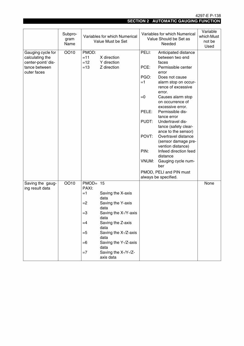
4297-E P-138SECTION 2 AUTOMATIC GAUGING FUNCTION
Gauging cycle for calculating the center-point/ dis-tance between outer faces
OO10 PMOD:=11=12=13
X directionY directionZ direction
PELI:
PCE:
PGO:=1
=0
PELE:
PUDT:
POVT:
PIN:
VNUM:
Anticipated distance between two end facesPermissible center errorDoes not cause alarm stop on occur-rence of excessive error.Causes alarm stop on occurrence of excessive error.Permissible dis-tance errorUndertravel dis-tance (safety clear-ance to the sensor)Overtravel distance (sensor damage pre-vention distance)Infeed direction feed distanceGauging cycle num-ber
PMOD, PELI and PIN must always be specified.
Saving the gaug-ing result data
OO10 PMOD=PAXI:=1
=2
=3
=4
=5
=6
=7
15
Saving the X-axis dataSaving the Y-axis dataSaving the X-/Y-axis dataSaving the Z-axis dataSaving the X-/Z-axis dataSaving the Y-/Z-axis dataSaving the X-/Y-/Z-axis data
None
Subpro-gram Name
Variables for which Numerical Value Must be Set
Variables for which Numerical Value Should be Set as
Needed
Variable which Must
not be Used

4297-E P-139SECTION 2 AUTOMATIC GAUGING FUNCTION
Gauging cycle for calculating the center-point/ dis-tance between two points
OO10 PMOD=PAXI:=1
=2
=3
=4
=5
=6
=7
14
Calculation on the X-axisCalculation on the Y-axisCalculation on the X-/Y-axisCalculation on the Z-axisCalculation on the X-/Z-axisCalculation on the Y-/Z-axisCalculation on the X-/Y-/Z-axis
PE:PXCI:
PXCE:
PXLI:
PXLE:
PYCI:
PYCE:
PYLI:
PYLE:
PZCI:
PZCE:
PZLI:
PZLE:
PGO:=1
Permissible errorAnticipated center position - XPermissible center position error - XAnticipated dis-tance - X-XPermissible dis-tance error - X-XAnticipated center position - YPermissible center position error - YAnticipated distance - Y-YPermissible dis-tance error - Y-YAnticipated center position - ZPermissible center position error - ZAnticipated distance - Z-ZPermissible dis-tance error - Z-Z
Does not cause alarm stop on occur-rence of excessive error.
None
Automatic zero offset
OO20 PHN:
PX:
PY:
PZ:
Coordinate system number for which zero point is offsetX coordinate value after zero offsetY coordinate value after zero offsetZ coordinate value after zero offset
None
Subpro-gram Name
Variables for which Numerical Value Must be Set
Variables for which Numerical Value Should be Set as
Needed
Variable which Must
not be Used

4297-E P-140SECTION 2 AUTOMATIC GAUGING FUNCTION
5-3-2. How to Use Variables
Eeoemr5s2048(1) PMOD (P MODE)Designates the automatic gauging mode.
(2) PDI (P DIAMETER IDEAL VALUE)Sets the anticipated diameter in the ID/OD gauging cycles.
(3) PDE (P DIAMETER ERROR LIMIT)Sets the permissible error of the diameter for the ID/OD gauging cycles as an absolute value.The hole dia. error over alarm occurs if:PDE < | PDl - (Actual measured value of the diameter) |The value obtained from the measurement in the X-axis direction is used as the actual mea-sured value.With the horizontal spindle of the MCM, the value measured in either the X- or Y- axis directionis used as the actual measured value.The measured diameter is not evaluated if PDE is not set. In this case, the result of judgment isalways OK.
(4) PCE (P CENTER ERROR LIMIT)Sets the permissible error of the center position of a circle as an absolute value for ID/OD gaug-ing cycles.The X-axis permissible error, the Y-axis permissible error and Z-axis permissible error cannotbe set individually.The excessive off-center alarm occurs when,PCE < | (Anticipated center of X-axis) - (Actual measured center of X-axis) |PCE < | (Anticipated center of Y-axis) - (Actual measured center of Y-axis) |PCE < | (anticipated center of Z-axis) - (actual measured center of Z-axis) | (for MCM horizontalspindle)The anticipated centers of the X-, Y- and Z-axis are the actual positions of the X-, Y- and Z-axiswhen the ID/OD gauging subprograms are called during the execution of a part program.Error in the measured center position is not evaluated if PCE is not set.
(5) PIN (P IN)/PZIN (P Z IN)Sets the Z-axis direction infeed distance as a relative value (positive incremental amount) forthe OD gauging cycle
(6) PEI (P EDGE IDEAL VALUE)Sets the end face position of the gauging target for the X-, Y- and Z-axis end face gaugingcycles and the touch probe length offset cycle.
(7) PEE (P EDGE ERROR LIMIT)Sets the permissible error of the end face position for an end face gauging cycle.The excessive off-center alarm occurs when,PEE< | PEI - (Actual measured value of end face) |Error in the measured end face position is not evaluated if PEE is not set.
PMOD Setting Gauging Mode
1 End face gauging cycle (X-axis)
2 End face gauging cycle (Y-axis)
3 End face gauging cycle (Z-axis)
6 OD gauging cycle
7 ID gauging cycle
8 Touch probe length offset
9 Touch probe radius compensation
14Calculation of center and distance
between two points
15 Saving of the measurement results

4297-E P-141SECTION 2 AUTOMATIC GAUGING FUNCTION
(8) PUDT (P UNDER TRAVEL)Sets the undertravel distance as an absolute value.During the execution of a gauging cycle, the touch probe moves to a position a certain amountaway from the anticipated contact detection position at a fast feedrate. This amount is set usingPUDT.If no value is set for PUDT, the undertravel distance is automatically set at 10 mm.The gauging impossible alarm occurs when the touch probe comes into contact with the work-piece while it is advancing at a fast feedrate up to this position. If an occurrence of this error issuspected, PUDT should be set. Usually, set a value larger than 3 mm.For the designation of PUDT, see examples 1 to 4.
(9) POVT (P OVER TRAVEL)Sets the overtravel distance as absolute values.During the execution of a gauging cycle, the touch probe moves to a position PUDT away fromthe anticipated contact detection position at a fast feedrate. After this positioning, the touchprobe moves to a position a certain amount beyond the anticipated contact detection position ata medium-fast feedrate. This amount is set using POVT.If no value is set for POVT, the overtravel distance is automatically set at 10 mm.The gauging impossible alarm occurs when the touch probe fails to contact the workpiece evenon reaching the position determined by POVT. If an occurrence of this error is suspected,POVT should be set.For the designation of POVT, see examples 1 to 4.
CAUTION
EIOEMR5S2033R01
Since the touch probe stops when it comes into contact with the workpiece, setting a largevalue for POVT will generally not cause a problem. However, it could cause the touch probeunit to strike the workpiece if a contact signal is not output due to the failure of the touchprobe itself.When an axis movement command larger than the touch probe stylus stroke is set, the touchprobe will be damaged if the contact signal is not output due to the failure of the touch probeitself.Therefore, do not set an unnecessarily large value for POVT.
Example 1: PUDT and POVT not designatedIf PUDT and POVT are not designated, 10 mm is automatically set as the undertravel and overtravel distance.Example program:CALL OO10 PMOD=1 PEI=40
Anticipated position
Actual position
Touch probe stops if contact signal is not output.
X40 X43 X50
POVT=10PUDT=10
X30

4297-E P-142SECTION 2 AUTOMATIC GAUGING FUNCTION
EIOEMR5S2034R01
EIOEMR5S2035R01
[Supplement]
EIOEMR5S2036R01
Example 2: Only POVT designatedExample program:CALL OO10 PMOD=1 PEI=40 POVT=2
Example 3 Only PUDT designated (PUDT = 15)Example program:CALL OO10 PMOD=1 PEI=40 PUDT=15
Determine the PUDT value taking into consideration the allowable over-stroke of the touchprobe.
Example 4: Both POVT and PUDT designated (POVT = 5, PUDT = 15)Example program:CALL OO10 PMOD=1 PEI=40 POVT=5
Touch probe stops if contact signal is not output.
Set so that this distance is smaller than the allowable over-stroke of the touch probe.
X42X40X35X30
POVT=2
7mm
PUDT=10
Touch probe stops if contact signal is not output.
X50X40X30X25
PUDT=15 POVT=10
Touch probe stops if contact signal is not output.
X45X40X35X25
PUDT=15 POVT=5

4297-E P-143SECTION 2 AUTOMATIC GAUGING FUNCTION
(10) PMSR (P MEASURE)Usually, contact detection is executed two times in the X-axis direction when an ID/OD gaugingcycle is executed. If “PMSR = 1” is set, however, the second contact detection cycle is not exe-cuted.When the touch probe is set in the horizontal spindle of MCM, the second contact detectioncycle in the X or Y-axis direction is not executed.
(11) PGO (P GO)
• When “PGO = 1” is set, an alarm does not occur if the results obtained from the gaugingcycle exceed the permissible range. When “PGO = 1” is set, judge the results of gauging(OK/NG) in a part program by reading system variable VOK1 after the completion of an auto-matic gauging subprogram.“VOK1 = 0” when the result is OK.
• Another system variable, VOK2, is also used for storing the result of the gauging cycle. Dif-fering from system variable VOK1, which holds the result of the dimension check cycle exe-cuted immediately before its designation, VOK2 indicates, if “VOK2 ≠ 0”, an occurrence thatthe result of any one of dimension check cycles has exceeded the permissible error in all ofthe dimension check cycles executed after VOK2 has been reset to 0 (VOK2 = 0).
• In the case of the gauging impossible alarm, zero offset impossible alarm, command missingerror alarm or no subprogram function alarm, the CNC is alarm-stopped even if “PGO = 1” isset.When PGO is not set, the CNC is alarm-stopped when the gauging cycle results haveexceeded the permissible error also.
EIOEMR5S2037R01
With the program above, the diameter of the hole finished by boring operation is measured(N24). If the hole diameter is within a specified range (φ79.95 to φ80.05 mm), the machiningcycle is continued. If the diameter is larger than φ80.05 mm, the workpiece is determineddefective and the machining cycle is halted.If the diameter is smaller than φ79.95 mm, execution of the program is interrupted by the M0command in N27. This allows the operator to adjust the boring bit, to carry out the boringcycle on the same hole again.
(12) VNUM (V NUM BER)Sets the gauging cycle number (range: 0 to 9999).Before the execution of an ID/OD gauging cycle, touch probe length offset, or touch proberadius compensation cycle, the present VNUM value is increased by “1” and the new number isprinted as the gauging cycle numberOnce designated, VNUM is automatically increased by “1” at each execution of a gauging cycleto be printed.
Program example with "PGO = 1" setting .
.N24 CALL OO10 PMOD=7 PDI=80 PDE=0.05 PGO=1.......... ID gaugingN25 IF [VOK1 EQ 0] N29 ........................................................ Jumps to N29 if the result is OK.N26 IF [VC930 GT 80000] N100.............................................. Jumps to N100 if the diameter is
greater than φ80.05 mm.N27 M0N28 GOTO N18 ....................................................................... Re-machiningN29 M6N30 T10N31 G0 X140 Y0 .
.

4297-E P-144SECTION 2 AUTOMATIC GAUGING FUNCTION
(13) PAXI (P AXIS)Sets the target axes for saving the gauging cycle results or for calculating the center and dis-tance between two points.
(14) PHN (P H NUMBER)Sets the work coordinate system number for which zero offset is executed using the automaticzero offset function.When PHN is not set, this results in a command missing alarm.
(15) PX, PY, PZThese variables set the coordinate values that the actual position should take after offsetting ofthe zero point by the automatic zero offset function.Set the coordinate value only for the axes on which zero offset is required.For the undesignated axes, the zero offset data remains unchanged.
a) Execute the ID gauging cycle.
b) Execute the following program.CALL OO20 PHN=2 PX=10 PY=50
(16) PXCI (P X CENTER IDEAL VALUE)/PYCI (P Y CENTER IDEAL VALUE)/PZCI (P Z CENTER IDEAL VALUE)These variables set the anticipated values of the center between two points (X-X, Y-Y, Z-Z) inthe calculation of the center/distance between two points.When these values are not set, the center position obtained as the result of a gauging cycleresult is not evaluated.
(17) PXCE (P X CENTER ERROR LIMIT)/PYCE (P Y CENTER ERROR LIMIT)/PZCE (P Z CENTER ERROR LIMIT)These variables set the permissible errors in the position of the center between two points (X-X,Y-Y, Z-Z) in the calculation of the center/distance between two points. Designate absolute val-ues.When these values are not set, the center position obtained as the result of a gauging cycle isnot evaluated.
(18) PXLI (P X LENGTH IDEAL VALUE)/PYLI (P Y LENGTH IDEAL VALUE)/PZLI (P Z LENGTH IDEAL VALUE)These variables set the anticipated distances between two points (X-X, Y-Y, Z-Z) in the calcula-tion of the center/distance between two points.When these values are not set, the distance between two points obtained as the results of agauging cycle result is not evaluated.
PAXI Setting Target Axes
1 X-axis
2 Y-axis
3 X- and Y-axis
4 Z-axis
5 X- and Z-axis
6 Y- and Z-axis
7 X-, Y- and Z-axis
Example: The procedure for offsetting the zero point of work coordinate system No. 2 so that the center of an inner diameter will have the coordinate values X = 10, Y = 50 is described below.

4297-E P-145SECTION 2 AUTOMATIC GAUGING FUNCTION
(19) PXLE (P X LENGTH ERROR LIMIT)/PYLE (P Y LENGTH ERROR LIMIT)/PZLE (P Z LENGTH ERROR LIMIT)These variables set the permissible errors in the distances between two points (X-X, Y-Y, Z-Z) inthe calculation of the center/distance between two points. Designate absolute values.When these values are not set, the distance between two points obtained as the results of agauging cycle result is not evaluated.
(20) PE (P ERROR)For the designation of the cycle to calculate the center/distance between two points, if the samevalue is assigned to permissible error values of the center position and the distance, variablePE can replace the designation of PXCE, PYCE, PZCE, PXLE, PYLE and PZLE.The following two programs have the same effect.PXCE=0.01 PYCE=0.01 PZCE=0.01 PXLE=0.01 PYLE=0.01 PZLE=0.01PE=0.01Note that PE is given priority over PXCE, PYCE, PZCE, PXLE, PYLE and PZLE. Therefore,take care when using PE with other variables.If the setting is, for example, as indicated belowPE=0.01 PZCE=0.02 PZLE=0.03it is the same asPE=0.01 PZCE=0.01 PZLE=0.01
(21) PELI (P EDGE LENGTH IDEAL VALUE)Sets the anticipated distance between two faces.
(22) PELE (P EDGE LENGTH ERROR LIMIT)Sets the permissible error between the distance set for PELI and the actual measured value.

4297-E P-146SECTION 2 AUTOMATIC GAUGING FUNCTION
5-3-3. Common Variables for Storing Gauging Cycle Results
Eeoemr5s2049After the execution of an automatic gauging cycle, the obtained results can be checked by displayingthe GAUGING RESULTS screen. In addition to this check, the results can be used in a part pro-gram to control program flow and other processing since they are stored in the common variablesindicated below.
Note that referencing of the common variables indicated above is not allowed in the usual commonvariable reference method. To use the data stored in these common variables, move it to other com-mon variables that can be referenced.To reference the end face gauging result in the X-axis direction, move the data to VC1, for example,by specifying “VC1 = VS29”, then read common variable VC1 in a part program.
[Supplement]
Type of Gauging CycleCommon Variable
Type of Gauging CycleCommon Variable
Type of Gauging
Cycle
Common Variable
ID gauging: Center (X)
ID gauging: Center (Y)
ID gauging: ID
VS29
VS28
VS30
Data saving: X-axis data
Data saving: Y-axis data
Data saving: Z-axis data
VS26
VS25
VS24
End face gauging: X-
axis dataEnd face
gauging: Y-axis dataEnd face
gauging: Z-axis data
VS29
VS28
VS27
OD gauging: Center (X)
OD gauging: Center (Y)
OD gauging: OD
VS29
VS28
VS30
Center between two points (X)
Center between two points (Y)
Center between two points (Z)
VS29
VS28
VS27
— —
When the CNC is reset or the operation mode is changed to manual after the execution of a gaug-ing cycle, the data obtained in this gauging cycle is cleared. In this case, it is necessary to executethe gauging cycle again.

4297-E P-147SECTION 2 AUTOMATIC GAUGING FUNCTION
6. Touch Probe Safety Measures
6-1. Checking Proximity Switch OperationEeoemr5s2050The touch probe signal is transmitted by the proximity switch. However, when chips adhere to the
proximity switch, the touch probe signal may not be transmitted.To check if the proximity switch is operating correctly, the following sequence is executed when anautomatic gauging cycle is executed.
Machine operation(1) The touch probe signal is checked when an automatic gauging cycle subprogram OO10 is
called.
(2) If the signal is not output, the Z-axis moves to the travel end in the positive (+) direction and thespindle starts rotating to remove chips.
(3) If the output of the signal is not confirmed even after the check above is repeated several times,the operation is stopped by the gauging impossible alarm.If the output of the signal is confirmed, the axes move to the gauging cycle start point at a rapidfeedrate.
[Supplement]1) When the touch probe is set in the spindle manually, carry out this operation to confirm that the
signal is transmitted even if the proximity switch seems to be functioning correctly.2) When the touch probe is set in the spindle manually, always orient the spindle before calling an
automatic gauging cycle subprogram.3) With the FM type touch probe, operations of the proximity switch are not checked.

4297-E P-148SECTION 2 AUTOMATIC GAUGING FUNCTION
6-2. Replacing the Touch Probe BatteryEeoemr5s2051The FM type touch probe has a battery incorporated in its body.
If a gauging cycle is executed while the battery voltage is low, the touch probe fails to function nor-mally and the gauging cycle impossible alarm occurs.
(1) Checking the BatteryPress the battery ON switch halfway with the touch probe detached from the spindle.The low battery voltage indicating LED should light in this condition.If it is not lit, replace the battery.If the low battery voltage indicating LED is blinking while the touch probe is set in the spindle,replace the battery soon.
(2) Replacing the BatteryTo replace the battery, follow the procedure indicated below. Take care not to bend the antennaand battery holder while replacing the battery.
EIOEMR5S2038R01
Procedure :
1 Remove the cover clamp nut and the cover.The battery incorporated in the touch probe body will be exposed.
2 Remove the battery from the battery holder.
3 Disconnect the battery connector and replace the battery with a new one.
[Supplement]1) Battery type: Type OO6P (9 V, 2 pcs.)2) Battery life: Approx. 40 hours in continuous use3) You are recommended to remove the battery from the touch probe unit and store it properly
when the touch probe is not used.
Battery and holder
Cover clamp nut
Stylus
Low battery voltage indicating LED
Transmission antenna
There are two types of battery ON switch.
Battery ON switchCover
4297-E P-149SECTION 2 AUTOMATIC GAUGING FUNCTION
7. Supplementary InformationEeoemr5s2054Supplementary information relating to the automatic gauging function is given below. Before using
this function, make sure you fully understand the information below.
(1) All commands for programs are given in units of 1 mm or 0.001 mm. Commands should begiven in the unit presently selected.Commands cannot be given in units of 0.01 mm.
(2) Cutter radius compensation mode cancel command (G40) is executed in an automatic gaugingcycle subprogram.Note that S commands may be changed due to the execution of an automatic gauging cyclesubprogram.
(3) Do not call an automatic gauging cycle subprogram while a shift amount in a manual interven-tion operation remains.If an automatic gauging cycle subprogram is called in this state, the gauging impossible alarmoccurs.
(4) The work coordinate system cannot be changed during the execution of an automatic gaugingcycle subprogram.
(5) The user area for tape storage length, number of work coordinate sets, number of tool offsetsets, and common variables is not used in execution of an automatic gauging cycle subpro-gram.
(6) Do not execute an automatic gauging/automatic zero offset cycle while using a local coordinatesystem or the graphics enlarge/reduction mode.
(7) The permissible nesting level of subroutines during the execution of an automatic gauging sub-program is two.Accordingly, nesting of the maximum of six levels is possible only when the automatic gaugingfunction is called.
(8) Do not call an automatic gauging subprogram in the machine coordinate system (H0).
(9) As with other tools, you are recommended to set the same number as the touch probe toolnumber for VSTOH[5] as the tool offset number. This facilitates program and other checkingsince the touch probe length offset data can be checked in the same way as for other tools.
(10) When setting a value for POVT, the restrictions indicated below apply. When a 100% feed over-ride is set, the feedrate is F1000.Example
[Supplement]
(11) The diameter of holes or bosses to be measured must be larger than φ20 mm.
(12) With MCM series machining centers, index the swivel head to the rear position (M75) when set-ting the touch probe in the vertical spindle.If the touch probe is set in the vertical spindle with the swivel head at a position other than therear position, an alarm occurs (UNTENDED: gauging impossible 3C).Note that the automatic or MDI mode must be selected when mounting the touch probe in thevertical spindle.
1st Approach Speed (Feed Override Setting) Min. POVT Setting
F1000 (100%) 2 mm
F1500 (150%) 3 mm
F2000 (200%) 4 mm
The minimum value of POVT varies within a range of 2 to 5 mm depending on the servo char-acteristics.

4297-E P-150SECTION 2 AUTOMATIC GAUGING FUNCTION
(13) With MCM series machining centers, never execute the zero point setting cycle (OO21) for thedatum hole with the horizontal spindle.
(14) The direction of touch probe mounting in the spindle is determined by the machine model.Therefore, pay attention to the direction when manually mounting the touch probe in the spin-dle.
(15) To check the touch probe function, follow the steps indicated below.
a) After entering “VNCOM[1] = 8” in the MDI mode, press the CYCLE START button.
b) Manually move the touch probe right and left.
c) The characters “touch probe” on the screen (position display screen) are highlighted if thetouch probe is operating correctly.The data at VNCOM[1] is reset to “0” when the CNC is reset or the operation mode ischanged to manual.In this state, the displayed characters do not change even when the touch probe is moved.
CAUTIONIf the touch probe is manually set in the horizontal spindle of an MCM series machining center toexecute the touch probe radius compensation cycle, always set the horizontal spindle tool com-mand on the TOOL DATA SET screen.Otherwise, the Z-axis will move and the touch probe will be broken.
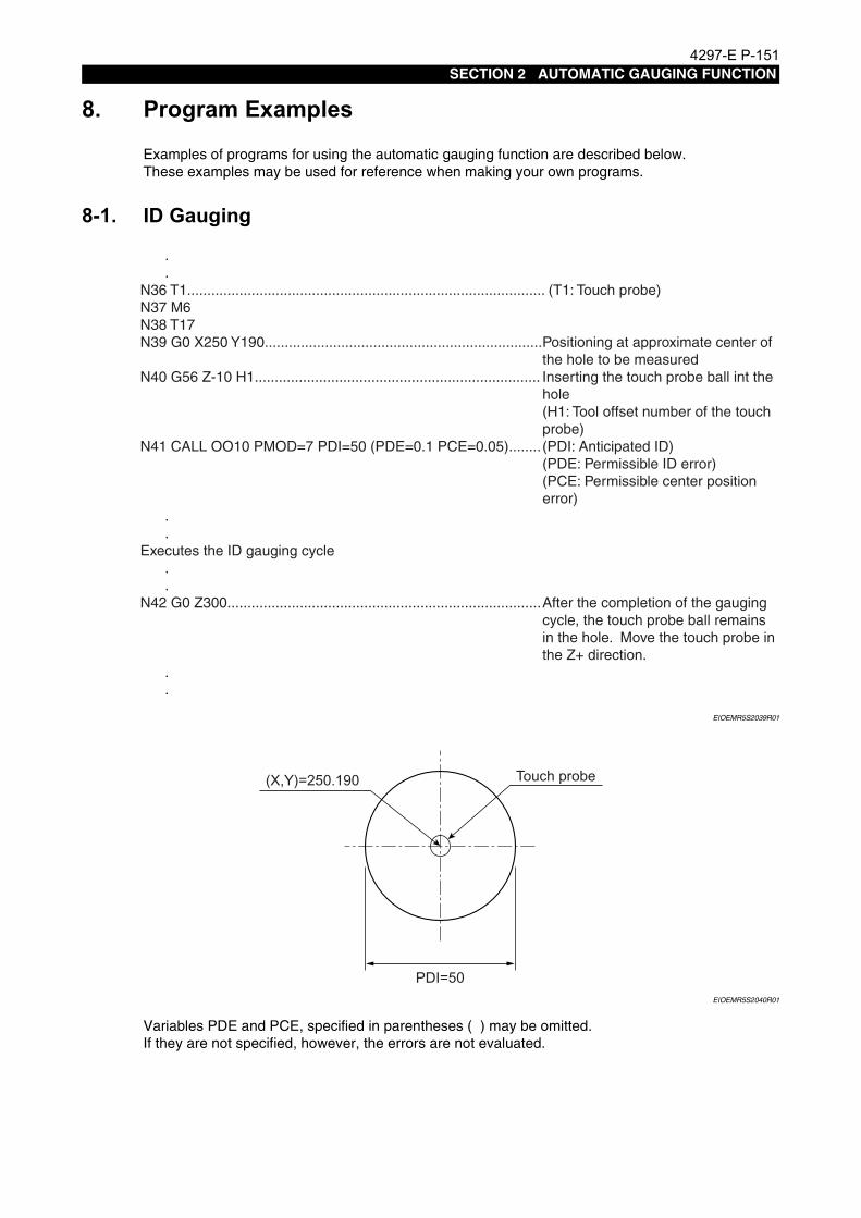
4297-E P-151SECTION 2 AUTOMATIC GAUGING FUNCTION
8. Program ExamplesEeoemr5s2055Examples of programs for using the automatic gauging function are described below.
These examples may be used for reference when making your own programs.
8-1. ID GaugingEeoemr5s2056
EIOEMR5S2039R01
EIOEMR5S2040R01
Variables PDE and PCE, specified in parentheses ( ) may be omitted.If they are not specified, however, the errors are not evaluated.
.
.N36 T1......................................................................................... (T1: Touch probe)N37 M6N38 T17N39 G0 X250 Y190.....................................................................Positioning at approximate center of
the hole to be measuredN40 G56 Z-10 H1....................................................................... Inserting the touch probe ball int the
hole(H1: Tool offset number of the touch probe)
N41 CALL OO10 PMOD=7 PDI=50 (PDE=0.1 PCE=0.05)........ (PDI: Anticipated ID)(PDE: Permissible ID error)(PCE: Permissible center positionerror)
.
.Executes the ID gauging cycle
. .N42 G0 Z300..............................................................................After the completion of the gauging
cycle, the touch probe ball remainsin the hole. Move the touch probe inthe Z+ direction.
.
.
(X,Y)=250.190 Touch probe
PDI=50
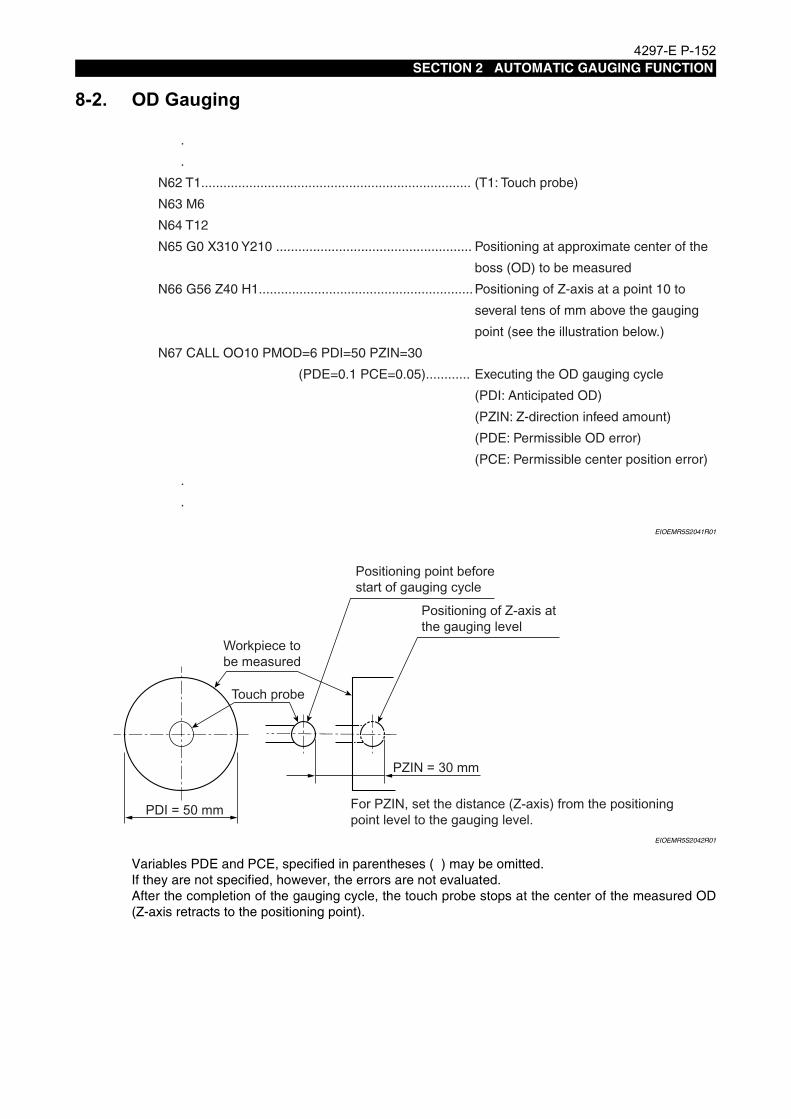
4297-E P-152SECTION 2 AUTOMATIC GAUGING FUNCTION
8-2. OD GaugingEeoemr5s2057
EIOEMR5S2041R01
EIOEMR5S2042R01
Variables PDE and PCE, specified in parentheses ( ) may be omitted.If they are not specified, however, the errors are not evaluated.After the completion of the gauging cycle, the touch probe stops at the center of the measured OD(Z-axis retracts to the positioning point).
.
.
N62 T1......................................................................... (T1: Touch probe)
N63 M6
N64 T12
N65 G0 X310 Y210 ..................................................... Positioning at approximate center of the
boss (OD) to be measured
N66 G56 Z40 H1..........................................................Positioning of Z-axis at a point 10 to
several tens of mm above the gauging
point (see the illustration below.)
N67 CALL OO10 PMOD=6 PDI=50 PZIN=30
(PDE=0.1 PCE=0.05)............ Executing the OD gauging cycle
(PDI: Anticipated OD)
(PZIN: Z-direction infeed amount)
(PDE: Permissible OD error)
(PCE: Permissible center position error)
.
.
Positioning point before start of gauging cycle
Positioning of Z-axis at the gauging level
PZIN = 30 mm
For PZIN, set the distance (Z-axis) from the positioning point level to the gauging level.
Workpiece to be measured
Touch probe
PDI = 50 mm

4297-E P-153SECTION 2 AUTOMATIC GAUGING FUNCTION
8-3. End Face Gauging on Z-axisEeoemr5s2058
EIOEMR5S2043R01
EIOEMR5S2044R01
Variable PEE, specified in parentheses ( ) may be omitted.If this variable is not specified, however, the error is not evaluated.
.
.
N95 T1.............................................................................. (T1: Touch probe)
N96 M6
N97 T4
N98 G0 X-25 Y60
N99 G56 Z80 H1
N100 CALL OO10 PMOD=3 PEI=35 (PEE=0.1).............. (PEI: Anticipated end face position)
(PEE: Permissible error)
N101 G0 Z300
.
.
Positioning at a point 10 to several tens mm away from the Z-end face to be measured
PEI = 35 mm
Position the touch probe ball at a point 10 to several tens of mm away from the target end face.
After the completion of the gauging cycle, the touch probe returns to the point where the first positioning was completed.

4297-E P-154SECTION 2 AUTOMATIC GAUGING FUNCTION
8-4. Distance between End Faces (X-axis direction)Eeoemr5s2059
EIOEMR5S2045R01
EIOEMR5S2046R01
Variables specified in parentheses ( ) may be omitted.If they are not specified, however, errors are not evaluated.When measuring the center and the distance between two points, the commands to store the firstgauging data in B memory are necessary (Example: N245 CALL OO10 PMOD=15).
.
.
N242 G0 X-20 Y60
N243 G56 Z-10 H1
N244 CALL OO10 PMOD=1 PEI=0 ........................... End face gauging cycle on end face A
N245 CALL OO10 PMOD=15 PAXI=1......................... Storing the result of gauging in B
memory
N246 G0 Z300
N247 X90
N248 G56 Z-10 H1
N249 CALL OO10 PMOD=1 PEI=70 .......................... End face gauging cycle on end face B
N250 CALL OO10 PMOD=14 PAXI=1
(PXCI=35 PXCE=0.05 PXLI=70 PXLE=0.05)............ Distance calculation cycle
(PXCI: Anticipated center position)
(PXCE: Permissible center position
error)
(PXLI: Anticipated distance between
end faces)
(PXLE: Permissible error of distance
between end faces)
N251 G0 Z300
.
.
N250 CALL OO10 PMOD=14...................................... No axis moves during the execution of
the distance calculationcycle
Positioning at a point 10 to several tens of mm away from one of the target end faces (end face A)
Positioning at a point 10 to several tens of mm away from the other target end face (end face B)
End face B
PXCI = 35
End face A
10 to Several tens of mm
Program zero
10 to Several tens of mm PXCI = 70

4297-E P-155SECTION 2 AUTOMATIC GAUGING FUNCTION
If these commands are not specified, the result of the first gauging cycle is overwritten by the resultof the next gauging cycle.For details on how to save the gauging result data refer to [2-7. Saving of Gauging Cycle Results].
8-5. Automatic Zero OffsetEeoemr5s2060
EIOEMR5S2047R01
EIOEMR5S2048R01
On execution of sequences N415 and N420, no axis moves.Execute the automatic zero offset cycle immediately after the execution of a gauging cycle (ID/ODgauging cycle, end face gauging cycle, center/distance between two points calculation cycle).Since an alarm occurs and zero offset is not executed if PHN is not set, always set it.
.
.
N412 G0 X40 Y50
N413 G56 Z-40 H1
N414 CALL OO10 PMOD=7 PDI=45 (PCE=0.03 PDE=0.05)..ID gauging cycle
N415 CALL OO20 PHN=5 PX=0 PY=0....................................For coordinate system No. 5, the
zero point (X = 0, Y = 0) is
established at the hole center
obtained by executing the ID
gauging cycle.
(PHN: Coordinate system No.)
N416 G0 Z300
N417 X60 Y60
N418 G56 Z-20 H1
N419 CALL OO10 PMOD=3 PEI=-30 (PEE=0.05)...................End face gauging cycle on Z- axis
N420 CALL OO20 PHN=5 PZ=0..............................................For the coordinate system No. 5,
the zero point (Z = 0) is
established at the end face
position obtained bexecuting the
end face gauging cycle
(Z-axis).N421 G0 Z300
Face A
Program zero
30
The zero point of coordinate system No. 5 is set at the hole center and the end face (face A).

4297-E P-156SECTION 2 AUTOMATIC GAUGING FUNCTION
8-6. Example Program for MCM Horizontal SpindleEeoemr5s2061
EIOEMR5S2049R01
2-10 DRILL
φ100 4-M20
4-M6XZ
Y
φ75

4297-E P-157SECTION 2 AUTOMATIC GAUGING FUNCTION
EIOEMR5S2050R01
.
.
N1 G15 H1.........................................................Selecting work coordinate system No. 1
N2 G0 X-500 Y800 G56 H1
N3 T1................................................................. T1: Touch probe
N4 M6
N5 T10 .............................................................. T10: φ17.5 drill
N6 G0 X0 Y0...................................................... Moving the X- and Y-axis to the anticipated
center of the φ100 mm hole
N7 Z-5 H1.......................................................... Moving the touch probe ball into the hole
(H1: Touch probe length offset data)
N8 CALL OO10 PMOD=7 PDI=100 POVT=3.... ID gauging cycle at φ100 mm hole
(PDI: Anticipated hole diameter)
(POVT: Overtravel distance)
N9 CALL OO20 PX=0 PY=0 PHN=1................. Zero offset according to the gauging results
(PX: X coordinate value after zero offset)
(PY: Y coordinate value after zero offset)
(PHN: Coordinate system No.)
N10 G0 Z100
N11 X75
N12 G56 Z30 H1............................................... Positioning of the Z-axis near the end face
(Z-axis)
N13 CALL OO10 PMOD=3 PEI=0 POVT=3 End face gauging cycle (Z-axis)
(PEI: Anticipated end face position)
N14 CALL OO20 PZ=0 PHN=1......................... Zero offset according to the gauging results
(PZ: Z coordinate value after zero offset)
N15 G0 Z400
N16 X500 Y800
N17 M6
N18 T11............................................................. T11: M20 tap
N19 NCYL G81 G56 R5 Z-58 F90 S450 H10....Part program for machining at the workpiece
upper face

4297-E P-158SECTION 2 AUTOMATIC GAUGING FUNCTION
EIOEMR5S2051R01
.
.
N49 G0 Z400
N50 X500 Y800
N51 M67
N52 M77
N53 T15
N54 G0 Y0 M75 ................................................ M75: Indexing the swivel head to the rear
position
N55 G54 X-500 H1
N56 Z-170 ........................................................ Moving the Y- and Z-axis to the anticipated
center of the φ75 mm hole
N57 X-270 ........................................................ Moving the touch probe ball into the hole
N58 CALL OO10 PMOD=7 PDI=75.................. ID gauging cycle at φ75 mm hole
N59 CALL OO20 PY=0 PZ=0 PHN=2 .............. Zero offset according to the gauging results
N60 G0 X-400
N61 Y60
N62 G54 X-300 H1............................................ Positioning of the X-axis near the end face
(X-axis)
N63 CALL OO10 PMOD=1 PEI=-280 .............. End face gauging cycle (X-axis)
N64 CALL OO20 PX=0 PHN=2 ....................... Zero offset according to the gauging results
N65 G0 X-400
.
.
Normal part program
.
.

4297-E P-159SECTION 2 AUTOMATIC GAUGING FUNCTION
9. Examples of Gauging Result DisplayEeoemr5s2064(1) Result of ID gauging
EIOEMR5S2053R01
(2) Result of OD gauging
EIOEMR5S2054R01

4297-E P-160SECTION 2 AUTOMATIC GAUGING FUNCTION
(3) Result of end face gauging (X-axis)
EIOEMR5S2055R01
(4) Result of end face gauging (Y-axis)
EIOEMR5S2056R01

4297-E P-161SECTION 2 AUTOMATIC GAUGING FUNCTION
(5) Result of end face gauging (Z-axis)
EIOEMR5S2057R01
(6) Result of calculation of the center/distance between two points
EIOEMR5S2058R01

4297-E P-162SECTION 2 AUTOMATIC GAUGING FUNCTION
10. Alarm List
10-1. Alarm ListEeoemr5s2062Name of Alarm Probable Cause Measures to Take
UNTENDED:gaugingimpossible(ALARM-B 2305)
At the end of the gauging impossible message, the cause code is dis-played.
Refer to the Gauging Impossible Cause Code Chart and eliminate the cause.
UNTENDED:no subprogramfunction(ALARM-B 2311)
Although there is no automatic zero offset specification, an attempt was made to call the automatic zero offset subprogram.
—
UNTENDED:commandmissing(ALARM-B 2308)
An undefined number was set for variable PMOD.
Check the value set at PMOD.
There is no PDI setting for ID/OD gauging cycle, or for touch probe radius compensation cycle.
For the ID/OD gauging cycle, set an anticipated diameter for PDI. For the touch probe radius compensation cycle, set an accurate ID for PDI.
There is no PHN setting in automatic zero offset commands.
Set the work coordinate system num-ber for which zero offset is to be exe-cuted for PHN.
There is no PEI setting for the end face gauging cycle (X, Y or Z), or for the touch probe length offset cycle.
For the end face gauging cycle, set an anticipated end face position for PEl. For the touch probe tool length offset cycle, set accurate Z end face position data for PEI.
UNTENDED:hole dia.error over(ALARM-B 2306)
The difference between the antici-pated diameter and the actual diame-ter obtained as the result of ID/OD gauging cycle has exceeded the per-missible error (PDE).
—
UNTENDED:off centerline(ALARM-B 2307)
The difference between the antici-pated center position and the actual center position obtained as the result of the ID/OD gauging cycle has exceeded the permissible error (PCE).
—
The difference between the antici-pated end face position and the actual end face position obtained as the result of the end face gauging cycle (X, Y, Z) has exceeded the per-missible error (PEE).
—
"ALARM-B 2305UNTENDED:
gauging impossible ××"↑
Cause code

4297-E P-163SECTION 2 AUTOMATIC GAUGING FUNCTION
UNTENDED:center distanceerror over(ALARM-B 2312)
The difference between the antici-pated value (center position and dis-tance between two points) and the actual value obtained as the results of the gauging and calculation cycle has exceeded the permissible error.
—
UNTENDED:zero offsetimpossible(ALARM-B 2310)
Since the results of the dimension check executed immediately before the automatic zero offset function were NG, zero offsetting is impossi-ble.
—
Automatic zero offset is executed although a dimension check is not executed.
Automatic zero offset is possible only after a dimension check has been executed.
Automatic zero offset is executed after pressing the RESET button fol-lowing the execution of a dimension check.
If the RESET button is pressed after executing the dimension check, the results of the gauging cycle are cleared and thus the automatic zero offset is impossible. In this case, the dimension check must be executed again.
Touch probebattery(ALARM-D 4223)
The battery incorporated in the Kuroda touch probe has expired. The life expiration signal is turned on. <I/O bit>I/O check No. 22 Bit 7 (MX-V series)ON (green): AbnormalOFF: NormalThe input bit position varies accord-ing to the machine model. For the bit position, refer to the wiring diagram.
Replace the battery.
Name of Alarm Probable Cause Measures to Take

4297-E P-164SECTION 2 AUTOMATIC GAUGING FUNCTION
10-2. Gauging Impossible Cause Code Chart (Alarm B 2305)Eeoemr5s2063Code
(HEX)Probable Cause Measures to Take
Used Subprograms
1 A maker subprogram is called while the machine coordinate system (H0) is selected
Call a maker subprogram after select-ing a work coordinate system (G15 H1, for example).
OO10OO30
2 The mirror image function is active. Cancel the mirror image function first. OO10OO30
3 Manual shift amount (total) remains. Cancel the manual shift amount (total) to zero.
OO10OO30
4 In the G11 mode (parallel or rotation shift of a coordinate)
Cancel the G11 mode first. OO10
5 In the G51 mode (graphics enlargement/reduction)
Cancel the G51 mode first. OO10
6 T number is zero (0), or no tool is set. • Specify a T number.
• Specify the PTLN command.
OO30
7 Specified T number or PTLN com-mand is larger than the maximum off-set number.
Specify a T number or PTLN com-mand within the allowable range.
OO30
8 The power to the probe is not on when the flash on cycle is attempted.
Check the following:
• Is there any obstacle between thereceiver head and the probe?
• Is the spindle index angle for theprobe correct?
• Does the receiver head flash?
OO15
9 The offset amount of the positioning point for cycle start from the touch sen-sor zero point is greater than PCHK(only for Y and Z axes).
When positioning the Y and Z axes, position them within the range of PCHK from the touch sensor zero point.
OO30
A The touch probe microcomputer stays on.
Check whether chips are accumulating on the proximity switch.
OO10
B The result of the touch probe test is NG.The touch probe signal cannot be con-firmed.
Check the touch probe battery. OO10
C The touch probe contacts the work-piece while it is being fed at a rapid approach feedrate (X-axis).
With the FM type touch probe, recep-tion of signals is not correct.
• Gauging cycle start point
• PUDT setting
OO10
D The touch probe fails to contact the workpiece while it is being fed at a middle approach feedrate (X-axis).
When using the FM type touch probe, signal reception is not correct.
• Gauging cycle start point
• POVT setting
OO10
E The touch probe fails to contact the workpiece while it is being fed at the final approach feedrate (X-axis).When using the FM type touch probe, signal reception is not correct.
Check the touch probe battery. OO10

4297-E P-165SECTION 2 AUTOMATIC GAUGING FUNCTION
F The proximity switch is not turned on although the touch probe is brought into contact with a workpiece (X-axis).
Check if the touch probe has chat-tered.
OO10
10 The touch probe contacts the work-piece while it is being fed at a rapid approach feedrate (Y-axis). When using the FM type touch probe, signal reception is not correct.
Check the following:
• Gauging cycle start point
• PUDT setting
OO10
11 The touch probe fails to contact the workpiece while it is being fed at a middle approach feedrate (Y-axis). When using the FM type touch probe, signal reception is not correct.
Check the following:
• Gauging cycle start point
• POVT setting
OO10
12 The touch probe fails to contact the workpiece while it is being fed at the final approach feedrate (Y-axis). When using the FM type touch probe, signal reception is not correct.
Check the touch probe battery. OO10
13 The proximity switch is not turned on although the touch probe is brought into contact with a workpiece (X-axis).
Check if the touch probe has chat-tered.
OO10
14 The touch probe contacts the work-piece while it is being fed at a rapid approach feedrate (Z-axis). When using the FM type touch probe, signal reception is not correct.
Check the following:
• Gauging cycle start point
• PUDT setting
OO10
15 The touch probe fails to contact the workpiece while it is being fed at a middle approach feedrate (Z-axis). When using the FM type touch probe, signal reception is not correct.
Check the following:
• Gauging cycle start point
• POVT setting
OO10
16 The touch probe fails to contact the workpiece while it is being fed at the final approach feedrate (Z-axis). When using the FM type touch probe, signal reception is not correct.
Check the touch probe battery. OO10
17 The proximity switch is not turned on although the touch probe is brought into contact with a workpiece (Z-axis).
Check if the touch probe has chat-tered.
OO10
18 The touch probe contacts the work-piece during the approach to the exter-nal diameter in the OD gauging cycle.
Check the following items:
• Start point of the gauging cycle
• Assumed OD value
OO10
19 PLH is not designated. Set tool length offset number for PLH.
1A PDH is not designated. Set the cutter radius compensation number for PDH.
Code(HEX)
Probable Cause Measures to TakeUsed
Subprograms

4297-E P-166SECTION 2 AUTOMATIC GAUGING FUNCTION
1B In the C-axis gauging cycle, contact is detected during the approach to the gauging point.
Check the following items:
• Is start point of the C-axis gaugingcycle correct?
• Is PDl value correct?
• Is PGI value correct?
OO10
1C Touch probe contact is not detected in X-axis direction motion within the range of PUDT and POVT. (contact value error)
OO100
1D Touch probe contact is not detected in Y-axis direction motion within the range of PUDT and POVT. (contact value error)
OO100
1E Touch probe contact is not detected in Z-axis direction motion within the range of PUDT and POVT. (contact value error)
OO100
1F In the touch sensor zero setting cycle for the vertical spindle longitudinal direction, the cutting tool fails to con-tact the sensor.
Check the start point of the cycle; is it close to the touch sensor (within 10 mm)?
OO30
20 In the touch sensor zero setting cycle for the vertical spindle radial direction, the cutting tool fails to contact the sen-sor.
Check the start point of the cycle; is it close to the touch sensor (within 10 mm)?
OO30
21 In the touch sensor zero setting cycle for horizontal spindle longitudinal direction, the cutting tool fails to con-tact the sensor.
Check the start position of the cycle; is it close to the touch sensor (within 10 mm)?
OO30
22 In the automatic tool length offset/automatic tool breakage detection cycle for the horizontal spindle in the radial direction, the cutting tool fails to contact the sensor.
Check the start point of the cycle; is it close to the touch sensor (within 10 mm)?
OO30
23 When the axis moves 0.5 mm in the positive direction from the contact detect point, the probe contact signal has already been on. (X direction)
OO100
24 When the axis moves 0.5 mm in the positive direction from the contact detect point, the probe contact signal has already been on. (Y direction)
25 When the axis moves 0.5 mm in the positive direction from the contact detect point, the probe contact signal has already been on. (Z direction)
Code(HEX)
Probable Cause Measures to TakeUsed
Subprograms

4297-E P-167SECTION 2 AUTOMATIC GAUGING FUNCTION
26 When the axis returns 0.5 mm from the contact position detected after approach (X direction), the value is taken as the coordinate value in the workpiece gauging direction again.
27 When the axis returns 0.5 mm from the contact position detected after approach (Y direction), the value is taken as the coordinate value in the workpiece gauging direction again.
28 When the axis returns 0.5 mm from the contact position detected after approach (Z direction), the value is taken as the coordinate value in the workpiece gauging direction again.
29 In the automatic tool length offset/automatic tool breakage detection cycle for the vertical spindle in the lon-gitudinal direction, the cutting tools fails to contact the sensor.
Check if the anticipated tool length is correct. (for tool length offset cycle)
OO30
2A In the automatic tool length offset/automatic tool breakage detection cycle for the vertical spindle in the radial direction, the cutting tools fails to contact the sensor.
Check the following items:
• Is the anticipated tool length cor-rect? (for tool length offset cycle)
• Is the cutter radius offset dataset? (for tool breakage detectioncycle)
OO30
2B In the automatic tool length offset/automatic tool breakage detection cycle for the horizontal spindle in the longitudinal direction, the cutting tool fails to contact the sensor.
Check the following items:
• Is the anticipated tool length cor-rect? (for tool length offset cycle)
• Is the cutter radius offset dataset? (for tool breakage detectioncycle)
OO30
2C In the automatic tool length offset/automatic tool breakage detection cycle for the vertical spindle in the radial direction, the cutting tool fails to contact the sensor.
Check the following items:
• Is the anticipated cutter radiuscorrect? (for tool length offsetcycle)
• Is the cutter radius offset dataset? (for tool breakage detectioncycle)
OO30
2D In the automatic tool length offset cycle in the X-axis direction (with angular attachment), the cutting tool fails to contact the sensor.
Check if PL1 is appropriate. OO30
33 In the U-center zero setting cycle, the cutting bit contacts the sensor, or the contact signal is input, in a sequence in which the cutting bit should not con-tact the sensor.
Check the following items:
• Is the sensor zero point set cor-rectly?
• Is the cutting bit free of chips?
• Is the sensor signal correct?
Code(HEX)
Probable Cause Measures to TakeUsed
Subprograms
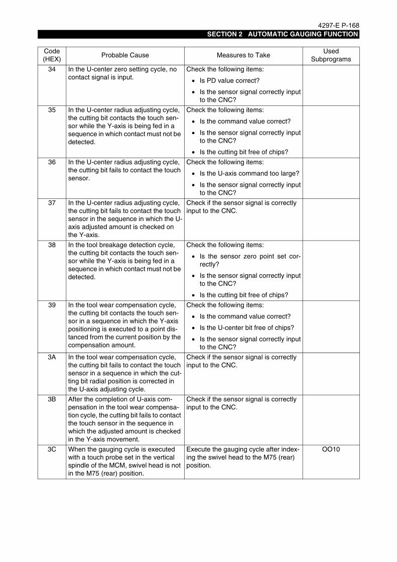
4297-E P-168SECTION 2 AUTOMATIC GAUGING FUNCTION
34 In the U-center zero setting cycle, no contact signal is input.
Check the following items:
• Is PD value correct?
• Is the sensor signal correctly inputto the CNC?
35 In the U-center radius adjusting cycle, the cutting bit contacts the touch sen-sor while the Y-axis is being fed in a sequence in which contact must not be detected.
Check the following items:
• Is the command value correct?
• Is the sensor signal correctly inputto the CNC?
• Is the cutting bit free of chips?
36 In the U-center radius adjusting cycle, the cutting bit fails to contact the touch sensor.
Check the following items:
• Is the U-axis command too large?
• Is the sensor signal correctly inputto the CNC?
37 In the U-center radius adjusting cycle, the cutting bit fails to contact the touch sensor in the sequence in which the U-axis adjusted amount is checked on the Y-axis.
Check if the sensor signal is correctly input to the CNC.
38 In the tool breakage detection cycle, the cutting bit contacts the touch sen-sor while the Y-axis is being fed in a sequence in which contact must not be detected.
Check the following items:
• Is the sensor zero point set cor-rectly?
• Is the sensor signal correctly inputto the CNC?
• Is the cutting bit free of chips?
39 In the tool wear compensation cycle, the cutting bit contacts the touch sen-sor in a sequence in which the Y-axis positioning is executed to a point dis-tanced from the current position by the compensation amount.
Check the following items:
• Is the command value correct?
• Is the U-center bit free of chips?
• Is the sensor signal correctly inputto the CNC?
3A In the tool wear compensation cycle, the cutting bit fails to contact the touch sensor in a sequence in which the cut-ting bit radial position is corrected in the U-axis adjusting cycle.
Check if the sensor signal is correctly input to the CNC.
3B After the completion of U-axis com-pensation in the tool wear compensa-tion cycle, the cutting bit fails to contact the touch sensor in the sequence in which the adjusted amount is checked in the Y-axis movement.
Check if the sensor signal is correctly input to the CNC.
3C When the gauging cycle is executed with a touch probe set in the vertical spindle of the MCM, swivel head is not in the M75 (rear) position.
Execute the gauging cycle after index-ing the swivel head to the M75 (rear) position.
OO10
Code(HEX)
Probable Cause Measures to TakeUsed
Subprograms

4297-E P-169SECTION 2 AUTOMATIC GAUGING FUNCTION
3D In the touch sensor zero setting cycle for the vertical spindle in the longitudi-nal direction on the MCM, the swivel head is not in the M73 (front) position, or the horizontal spindle is being used.
• Execute the cycle after indexingthe swivel head to the M73 (front)position.
• Check if the PAXI data is correct.
OO30
3E In the touch sensor zero setting cycle for the vertical spindle in the radial direction on the MCM, the swivel head is not in the M73 (front) position, or the horizontal spindle is being used.
• Execute the cycle after indexingthe swivel head to the M73 (front)position.
• Check if the PAXI data is correct
OO30
3F In the touch sensor zero setting cycle for the horizontal spindle in the longitu-dinal direction on the MCM, the swivel head is not in the M76 (right) position, or the horizontal spindle is being used.
• Execute the cycle after indexingthe swivel head to the M76 (right)position.
• Check if the PAXI data is correct
OO30
40 In the touch sensor zero setting cycle for the horizontal spindle in the radial direction on the MCM, the swivel head is not in the M76 (right) position, or the horizontal spindle is being used.
• Execute the cycle after indexingthe swivel head to the M76 (right)position.
• Check if the PAXI data is correct.
OO30
41 The tool number for the angular attachment is T52 or T53. (For the angular attachment tool, only T51 (90° angular attachment) can be used for tool length offset).
Check if the T command is correct.
42 The power supply for the optical type touch probe cannot be turned on.
OO16OO18
43 The power supply for the optical type touch probe cannot be turned off.
OO17OO19
Code(HEX)
Probable Cause Measures to TakeUsed
Subprograms

4297-E P-170SECTION 3 GAUGING DATA OUTPUT FUNCTION
SECTION 3 GAUGING DATA OUTPUT FUNCTION
1. OverviewEeoemr5s3001The gauging data output function outputs the gauging results obtained by executing the automatic
tool length offset/compensation function, automatic tool breakage detection function, or the auto-matic gauging function, to the connected RS-232C device.
1-1. ParametersEeoemr5s3002In order to use the gauging data output function, the parameters indicated below must be set.
EIOEMR5S3001R01
OUTPUT FUNCTION IS MADE EFFECTIVESets whether the output function is valid or invalid.
DESIGNATION OF OUTPUT DEVICESets the RS-232C channel device name.
RS232C STOP BITSets the number of stop bits for the designated RS-232C device.
Initial Setting Setting Range
DOES NOT DOES/DOES NOT
Initial Setting Setting Range
CN0: CN0:/CN1:/CN2:
Initial Setting Setting Range
2 1/2

4297-E P-171SECTION 3 GAUGING DATA OUTPUT FUNCTION
RS232C PARITY BITSets the parity scheme for the designated RS-232C device.
BAUD RATE (BPS)Sets the baud rate for the designated RS-232C device.
FLOW CONTROLSets the data processing method for the designated RS-232C device.
8bit JISSets if the characters set by 8-bit JIS code are directly output or converted into 7-bit JIS code for thedesignated RS-232C device.
READY WAITING TIMESets the waiting time for starting communications with the designated RS-232C device.If the device fails to get ready within the set length of waiting time, an alarm occurs.
1-2. Output OperationEeoemr5s3003It is possible to output the results of gauging after the execution of a workpiece gauging cycle, an
automatic tool length offset cycle or an automatic tool breakage detection cycle.Whether or not the results are output is set for system variable VPRT.VPRT = 1:Gauging results are output.VPRT = 0:Gauging results are not output.Before executing a gauging cycle, set “VPRT (=1 or 0)” in the MDI mode or automatic mode andpress the CYCLE START button.When the power is turned ON, the setting for VPRT is “VPRT = 0”.
Initial Setting Setting Range
ODD NON/EVEN/ODD
Initial Setting Setting Range
600 110 to 19200 [bps]
Initial Setting Setting Range
DC CODE DC CODE/BTR (NO DC CODE)/ RS/CS
Initial Setting Setting Range
8bit JIS 8bit JIS/7bit JIS
Initial Setting Setting Range
10 1 to 9999 [sec]

4297-E P-172SECTION 3 GAUGING DATA OUTPUT FUNCTION
1-3. Example ProgramEeoemr5s3004
EIOEMR5S3002R01
EIOEMR5S3003R01
R100
VPRT=1....................................................................... Output valid
G0 X0 Y0
G56 Z50 H1
M130
G1 Z-5 F1000
M131
CALL OO10 PMOD=7 PDI=200 ..................................Outputs the gauging results.
G0 Z500
VPRT=0 ...................................................................... Output invalid
G0 X0 Y0
G56 Z10 H1
CALL OO10 PMOD=6 PDI=200 PZIN=15 .................. Does not output the gauging results.
G0 Z500
M02
Touch probe length offset data

4297-E P-173SECTION 3 GAUGING DATA OUTPUT FUNCTION
1-4. Example of OutputsEeoemr5s3005The following shows an example of output of the gauging results.
EIOEMR5S3004R01
INSIDE DIAMETER No. 5 X Y D EXPECTED VALUE -42.227 49.911 30.150 PERMISSIBLE ERROR 0.050 0.050 MEASURED VALUE -42.228 49.911 30.152 DECISION OK
WORK SURFACE No. 6 X Y Z EXPECTED VALUE 0.000 PERMISSIBLE ERROR MEASURED VALUE 0.009 NO DECISION
OUTSIDE DIAMETER No. 11 X Y D EXPECTED VALUE 73.606 287.131 30.150 PERMISSIBLE ERROR 0.050 0.050 MEASURED VALUE 74.873 286.087 29.946 ALARM: ALIGNMENT OUT OF TOLERANCE
OUTSIDE DIAMETER No. 12 X Y D EXPECTED VALUE 74.896 286.085 29.050 PERMISSIBLE ERROR 0.050 0.050 MEASURED VALUE 74.896 286.086 29.946 DECISION OK ZERO OFFSET POSITION X Y ZCOORDINATES No. 19 60.256 286.086 . . . .TOOL LENGTH OFFSET: TOOL MANAGEMENT No. 29 COMPENSATED VALUE 0.400TOOL BREAKAGE DETECTION: TOOL MANAGEMENT No. 29 DECISION OK . .

4297-E P-174SECTION 3 GAUGING DATA OUTPUT FUNCTION
1-5. Output ItemsEeoemr5s3006The data to be output is indicated below.
Maker Subprogram
Gauging Mode Output Items
OO10
End face gauging
(1) Anticipated value (in the gaugingdirection)
(2) Permissible error (in the gaugingdirection)
(3) Actual measured value (in thegauging direction)
(4) Evaluation
ID/OD gauging
(1) Anticipated value (in the gaugingdirection)
(2) Permissible error (in the gaugingdirection)
(3) Actual measured value (in thegauging direction)
(4) Evaluation
Center/distance between two points
(1) Anticipated value (in the gaugingdirection)
(2) Permissible error (in the gaugingdirection)
(3) Actual measured value (in thegauging direction)
(4) Evaluation
OO20 Automatic zero offsetZero offset data of the work coordi-nate system for which automatic zero offset was executed.
OO30
Automatic tool length offsetTool length offset data of the tool for which automatic tool length offset was executed.
Automatic tool breakage detection
Tool breakage detection result of the tool for which automatic tool break-age detection was executed, and the tool breakage judging value when the tool breakage was detected.

4297-E P-175SECTION 3 GAUGING DATA OUTPUT FUNCTION
2. Interface Specifications for Connecting VP-600Eeoemr5s3007The interface specifications for connecting a VP-600 printer (Epson) are indicated below.
2-1. Connection DiagramEeoemr5s3008The signal connections between the VP-600 and CNC are shown below.
EIOEMR5S3005R01
FG 1
TxD 2
RxD 3
RTS 4
CTS 5
DSR 6
SG 7
CD 8
RG1 9
DTR 20
EX-INT 23
1 PG
3 RD
2 SD
7 SG
6 DSR
8 DCD
20 DTR
Signal Name
Pin No.Signal Name
Pin No.
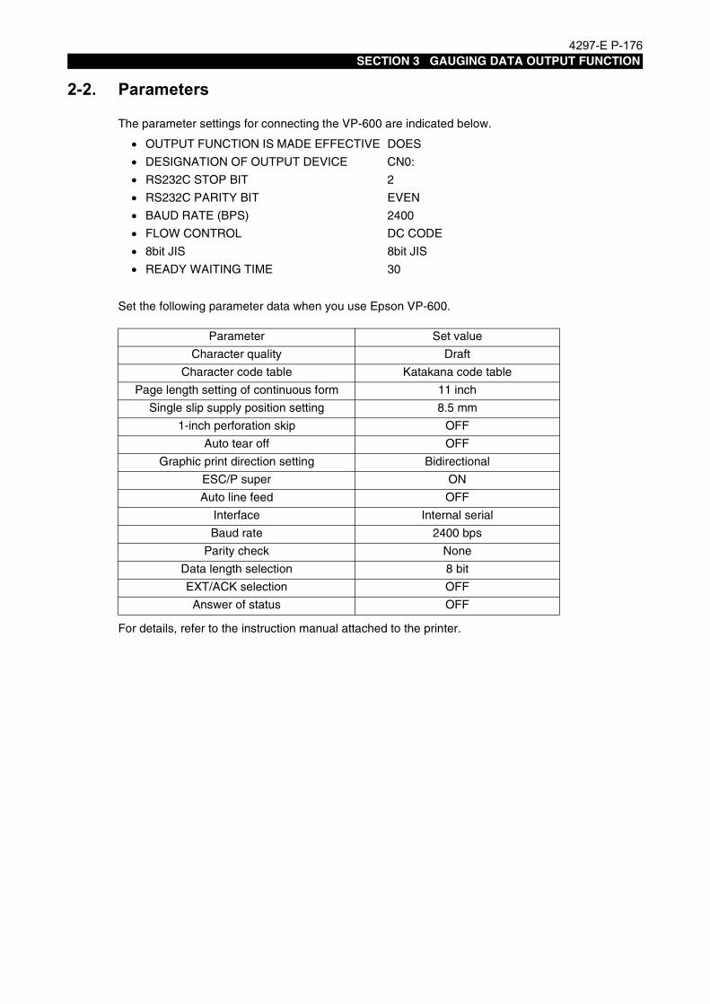
4297-E P-176SECTION 3 GAUGING DATA OUTPUT FUNCTION
2-2. ParametersEeoemr5s3009The parameter settings for connecting the VP-600 are indicated below.
Set the following parameter data when you use Epson VP-600.
For details, refer to the instruction manual attached to the printer.
• OUTPUT FUNCTION IS MADE EFFECTIVE DOES
• DESIGNATION OF OUTPUT DEVICE CN0:
• RS232C STOP BIT 2
• RS232C PARITY BIT EVEN
• BAUD RATE (BPS) 2400
• FLOW CONTROL DC CODE
• 8bit JIS 8bit JIS
• READY WAITING TIME 30
Parameter Set value
Character quality Draft
Character code table Katakana code table
Page length setting of continuous form 11 inch
Single slip supply position setting 8.5 mm
1-inch perforation skip OFF
Auto tear off OFF
Graphic print direction setting Bidirectional
ESC/P super ON
Auto line feed OFF
Interface Internal serial
Baud rate 2400 bps
Parity check None
Data length selection 8 bit
EXT/ACK selection OFF
Answer of status OFF

4297-E P-177SECTION 4 GAUGING DATA OUTPUT TO FILE
SECTION 4 GAUGING DATA OUTPUT TO FILE
1. OutlineEeoemr5sb001The print statement has been used to output the data and character strings of the variables to the
panel CRT or an external device (such as a printer).In addition to these output operations, this function allows output of the variables data to a file(MD1:A.MDF).
2. Parameters
2-1. NC Optional Parameter BitEeoemr5sb002
No. bit Description
2 4 The print function outputs variables data to an external device on reception of a print command.
Effective Ineffective
16 3 If a print command is issued while the file is accessed in the program operation mode or MD1: does not have enough free area, an alarm C will occur.
Alarm C"3237"
Alarm D"4262"
32 5 The print function outputs data to a file (A.MDF) regard-less of the variable data (VPRT) for designating the dis-playing device.
Does Does not

4297-E P-178SECTION 4 GAUGING DATA OUTPUT TO FILE
3. Designation of Displaying DeviceEeoemr5sb003The displaying device designation signal is output with a variable VPRT as shown in the table below.
4. Print CommandEeoemr5sb004The value or the character string of the specified variable is output to an external device such as a
printer, the panel CRT, or a file according to the variable (VPRT) for designating the displayingdevice.If a variable or a character string is omitted, only a line is fed. The area used to display the variabledata and character string are already divided and allocated to each system variable used. If a spaceis used as a delimiter, the variable data or character string is displayed immediately after the previ-ously printed data without line feed.
When the command 1) is specified, the specified variable data and the character strings are dis-played with normal characters. When the command 2) is specified, they are displayed with enlargedcharacters. When the command 3) is specified, they are displayed with normal characters withoutline feed.
Output deviceUnit of variables data
Minimum unit system
Standard unit system
Not output VPRT = 0 VPRT = 4
Output to an external device VPRT = 1 VPRT = 5
Output to the panel CRT VPRT = 2 VPRT = 6
Output to an external device and the panel CRT VPRT = 3 VPRT = 7
Output to a file VPRT = 8 VPRT = 12
Output to an external device and a file VPRT = 9 VPRT = 13
Output to the panel CRT and a file VPRT = 10 VPRT = 14
Output to an external device, the panel CRT, and a file VPRT = 11 VPRT = 15
Note 1 : Output to an external device is effective only when a checkmark is set at the checkbox of the NC optional parameter (bit) No.2, bit4.
Note 2 : If a checkmark is set at the checkbox of the NC optional parameter (bit) No. 32 bit 5, data is output to the file (MD1:A.MDF), regardless of the variable (VPRT) for designating the displaying device.
Note 3 : The gauging data obtained by execution of an MSB is not output to a file even when the relevant value is set at the variable VPRT.It is output only when a checkmark is set at the NC optional parameter (bit) No.32, bit 5.
Note 4 : For the output in minimum unit system or standard unit system, refer to the explanation about the print command of the floating-point variable described in 4-1, *3.
Command format 1) PRINT [<Expression> ---]
2) LPRINT [<Expression> ---]
3) SPRINT [<Expression> ---]
Sample statement PRINT "ABC"
Note 1: The LPRINT command (enlarged display) is effective only for the printer OKUMA PP-5000-EPSON. Enlarged characters are not displayed on the CRT panel or a file. They are dis-played with normal characters even though the LPRINT command is issued.

4297-E P-179SECTION 4 GAUGING DATA OUTPUT TO FILE
4-1. System Variables for PrintingEeoemr5sb005<Expression> Range Output example
VINTGInteger type variable[Sample statement] PRINT VINTG
-99999999 to 99999999 " -99999999"[12 digits]
VNUM[Sample statement] PRINT VNUM
-999 to 999 "NO. 9"[7 digits]
VOK1[Sample statement] PRINT VOK1
0 to 5, 10 to 15 Normal chars (Enlarged chars)" " VOK1=0 (VOK1=10)" OK" VOK1=1 (VOK1=11)"+OK" VOK1=2 (VOK1=12)"+NG" VOK1=3 (VOK1=13)"-NG" VOK1=4 (VOK1=14)" NG" VOK1=5 (VOK1=15)
[3 digits]
VOK2[Sample statement] PRINT VOK2
1, 2 "TOTAL OK" VOK2=1"TOTAL NG" VOK2=2
[8 digits]
VPCNTVariable for printer control code[Sample statement] SPRINT VPCNT
0 to 255(0 to 127) *2
$1F (hexadecimal 1 byte)When VPCNT=31
VC**, VPRTFloating-point variable[Sample statement] PRINT VC1
-99999999 to 999999999(Max 8 digits)
In millimetes" -99999.999"In inches" -9999.9999"
[12 digits]
"--------"Character string[Sample statement] PRINT "ABC"
Max number of characters: 80 "ABC"
#----HCharacters displayed in hexadecimal[Sample statement] PRINT #B1B2B3B4H
Max number of characters: 4 "aiue"
*1 : If the variable is EMPTY, a blank " " is output.
*2 : If you output the printer control code (VPCNT) without setting a checkmark at the NC optional parameter (bit) No.8, bit 0 (8bit JIS), the data from 0 to 127 ($00 to $7F) are output with the parity bit (bit7).When the PRINT VPCNT is specified, the line feed command is output after the printer con-trol code. Therefore if you want to output only the printer control code, specify the SPRINT VPCNT.

4297-E P-180SECTION 4 GAUGING DATA OUTPUT TO FILE
*3 : For the floating-point variable, the displayed data varies depending on weather the mini-mum unit system is selected or the standard one is selected for the VPRT that designates the displaying device (see item 3. Designation of Displaying Device).
Unit Description of floating-point variable Output example
Standard unit systemVPRT=4 to 7
Metric VC**=12.34 12.340
Inch VC**=12.34 12.3400
Minimum unit systemVPRT=0 to 3
Metric VC**=12.34 0.012
Inch VC**=12.34 0.0012
* When a checkmark is set at the checkbox of the NC optional parameter bit No. 3, bit 0, the inch unit system is selected. If not, metric is selected.The data, which can be displayed in minimum unit system, may exceed 8 digits if con-verted into the standard unit system. In that case, the following indication appears:" +OVER FLOW" or " -OVER FLOW"
*4 : Only the following codes are output to a file (MD1:A.MDF): space ! " # $ % & ' ( ) * + , - . / 0 to 9 : ; < = > ? @ A to Z [ \ ] a to z { | }(The other codes are replaced with "?".

4297-E P-181SECTION 5 MANUAL GAUGING
SECTION 5 MANUAL GAUGING
1. Overview
1-1. SpecificationsEeoemr5s4001The manual gauging function is used to set the zero point, tool length offset data, etc., using a touch
probe or a touch sensor.Differing from the automatic gauging and automatic tool length offset functions, the manual gaugingfunction sets the data in an interactive operation using comments displayed on the screen and alsospecially provided switches. Therefore, the operator does not have to learn special gauging functionprograms.This function allows you easy and quick data setting without referring to the programming manual,and can be used effectively in the following cases:
• Setting the zero point or the tool length offset data for machining a one-of-a-kind workpiece
• Setting the zero point or the tool length offset data for machining the first workpiece, and begin-ning production from the next workpiece, using the set data.
• Setting the zero point or the tool offset data when performing machining jobs by interrupting lotproduction using the same part program.

4297-E P-182SECTION 5 MANUAL GAUGING
1-2. Overview of Manual Gauging FunctionsEeoemr5s4002The following is an outline of the manual gauging functions.
General configuration of manual gauging functions is shown in [1-3. List of Display Screens].
1-2-1. Work Gauging Function
Eeoemr5s4003The work gauging function measures the workpiece length, hole diameter, center position, etc. usinga touch probe, and executes zero offset. Zero offset is automatically executed after the completionof a gauging cycle. To execute only measurement, skip the zero offset process.This work gauging function provides the following gauging patterns. Choose the appropriate patternaccording to the shape of the target to be measured.
(1) End face (X, Y, Z)
(2) Center of ID
(3) Center of OD
(4) Center between two internal faces
(5) Center between two external faces
(6) Inclination and corner
EIOEMR5S4001R01
[Supplement]Refer to [3-1. Preparation for Work Gauging/Tool Length Gauging Cycles] for the preparation nec-essary before starting a work gauging cycle.

4297-E P-183SECTION 5 MANUAL GAUGING
1-2-2. Tool Length Gauging Function
Eeoemr5s4004The tool length gauging function measures the tool length using a touch sensor and executes tooloffset according to the result of gauging.Use a reference tool, or a tool of whose length from the gauge line to the tool nose is known, as agauge.
EIOEMR5S4002R01
Either of the following two types of tool offset is executed.
• Relative offset typeThe difference between the measured length and the length of the tool used as the gauge istaken as the tool length offset data.
EIOEMR5S4003R01
• Absolute offset typeThe length from the gauge line to the tool nose is taken as the tool length offset data.
EIOEMR5S4004R01
Reference tool
"L" is registered as the tool length offset data.
L
Gauge line
"L" is registered as the tool length offset data.
L

4297-E P-184SECTION 5 MANUAL GAUGING
[Supplement]
1-2-3. Cutter Radius Gauging Function
Eeoemr5s4005The cutter radius gauging function measures the radius of a tool with a touch sensor oriented hori-zontally, and executes cutter radius compensation according to the result of gauging.Use a reference tool or a tool whose radius is known as a gauge.
EIOEMR5S4005R01
[Supplement]
Refer to [3-1. Preparation for Work Gauging/Tool Length Gauging Cycles] for the preparation nec-essary before starting a tool length gauging cycle.
Refer to [3-2. Preparation for Cutter Radius Compensation Cycle] for the preparation necessarybefore starting a cutter radius gauging cycle.

4297-E P-185SECTION 5 MANUAL GAUGING
1-2-4. Gauging Preparation Function
Eeoemr5s4006The gauging preparation function is provided to perform the preparatory steps required for the workgauging, tool length gauging or cutter radius gauging function. Execute this gauging preparationfunction before starting a manual gauging cycle.
EIOEMR5S4006R01
• Preparation for starting a work gauging cycleBefore starting a work gauging cycle, set the length offset data and the radius compensationdata (in the four directions X+, X-, Y+ and Y-) of the touch probe.After selecting “A. PREPARATION OF WORK GAUGING/TOOL LENGTH GAUGING”, executethe preparation functions in the order indicated below.
a) A-1. REFERENCE SURFACE SET (REF TOOL)
b) A-2. TOUCH PROBE LENGTH OFFSET
c) A-3. TOUCH PROBE RADIUS COMP
[Supplement]
• Preparation for starting a tool length gauging cycleBefore starting a tool length gauging cycle, select “A. PREPARATION OF WORK GAUGING/TOOL LENGTH GAUGING” then execute “A-1. REFERENCE SURFACE SET (REF TOOL)”.
• Preparation for starting a cutter radius gauging cycleBefore starting a cutter radius gauging cycle, select “B. PREPARATION OF CUTTER RADIUSGAUGING” then execute “B-1. REF POS SET FOR CUTTER RADIUS COMP”.
1) Once length offset and radius compensation have been executed for the touch probe, they donot need to be executed every time a work gauging cycle is executed. Execute them from timeto time as needed.
2) After a feeler has been replaced or a feeler strikes a workpiece or other object, touch probelength offset/radius compensation must always be executed.
3) To obtain high accuracy in the work gauging operation, the run-out of the touch probe must beminimized.

4297-E P-186SECTION 5 MANUAL GAUGING
1-3. List of Display ScreensEeoemr5s4007The screens used for manual gauging operation and configuration of them are shown below.
EIOEMR5S4007R01
Man
ual G
augi
ng M
enu
Cut
ter
Rad
ius
Gau
ging
Tool
Len
gth
Gau
ging
Wor
k G
augi
ng M
enu
End
Fac
e (X
, Y, Z
)O
D C
ente
rC
ente
r be
twee
n Tw
o E
xter
nal F
aces
ID C
ente
rC
ente
r be
twee
n Tw
o In
tern
al F
aces
Incl
inat
ion
and
Cor
ner
Gau
ging
Pre
para
tion
Men
u
Ref
eren
ce P
ositi
on S
ettin
g fo
r C
utte
r R
adiu
s C
ompe
nsat
ion
Touc
h P
robe
Rad
ius
Com
pens
atio
nTo
uch
Pro
be L
engt
h O
ffset
Ref
eren
ce F
ace
Set
ting
(Ref
eren
ce T
ool)

4297-E P-187SECTION 5 MANUAL GAUGING
2. Basic OperationEeoemr5s4008Since manual gauging is executed in the manual operation mode, all manual operations, such as
rapid feed, jog feed, and pulse handle feed, are permitted during the execution of a gauging cycle.When moving an axis to a position close to the target, move it at a rapid feedrate, and for the detec-tion of contact of the touch probe or touch sensor, move the axis using the pulse handle.The desired manual gauging function can be selected from the MANUAL GAUGING MENU screen.Display the MANUAL GAUGING MENU screen by following the procedure indicated below, then per-form the desired function.
Procedure :
1 Select the manual mode.
2 Press function key [F1] (MANUAL GAUGING).The operation mode changes to the manual gauging mode and the MANUAL GAUGINGMENU screen is displayed.
[Supplement]If function key [F1] MANUAL GAUGING is not displayed, press the [EXTENSION] key so that theMANUAL GAUGING function is assigned to [F1].
EIOEMR5S4008R01
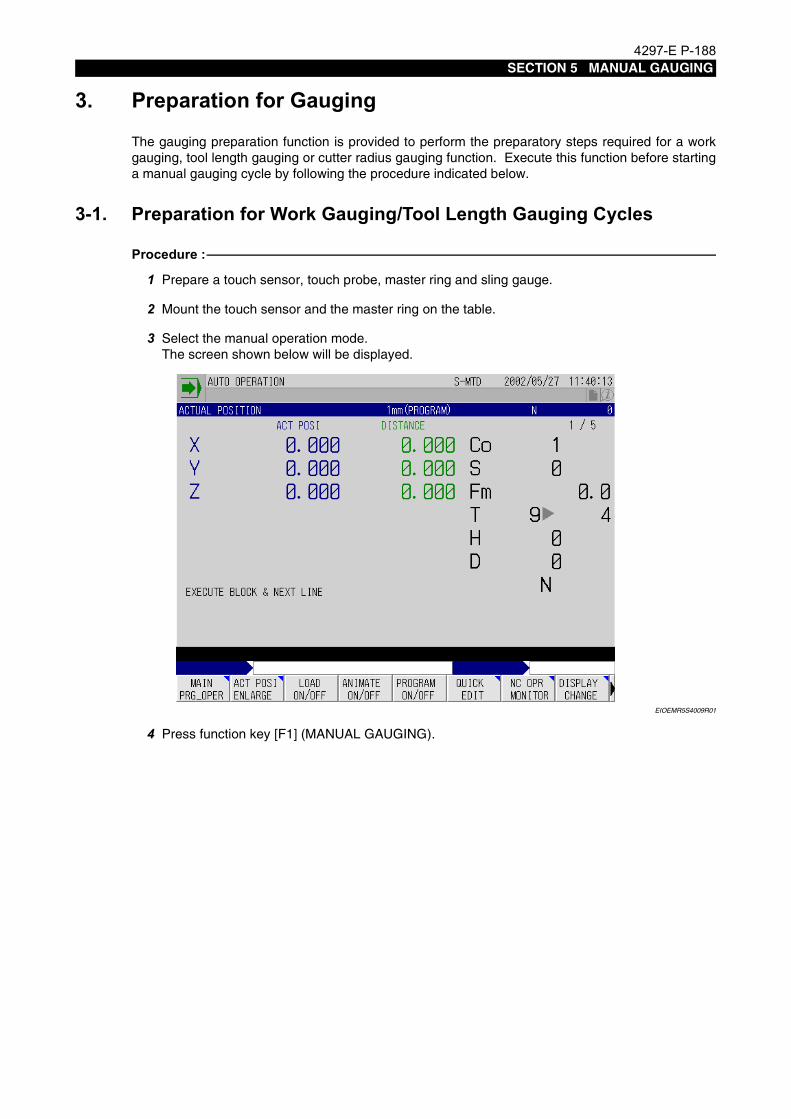
4297-E P-188SECTION 5 MANUAL GAUGING
3. Preparation for GaugingEeoemr5s4009The gauging preparation function is provided to perform the preparatory steps required for a work
gauging, tool length gauging or cutter radius gauging function. Execute this function before startinga manual gauging cycle by following the procedure indicated below.
3-1. Preparation for Work Gauging/Tool Length Gauging CyclesEeoemr5s4010Procedure :
1 Prepare a touch sensor, touch probe, master ring and sling gauge.
2 Mount the touch sensor and the master ring on the table.
3 Select the manual operation mode.The screen shown below will be displayed.
EIOEMR5S4009R01
4 Press function key [F1] (MANUAL GAUGING).

4297-E P-189SECTION 5 MANUAL GAUGING
The MANUAL GAUGING MENU screen, shown below, will be displayed.
EIOEMR5S4010R01
5 Press function key [F4] (GAUGING PREPAR).The GAUGING PREPARATION menu screen, shown below, will be displayed.
EIOEMR5S4011R01
[Supplement]The comment “MOVE CURSOR AND PRESS WRITE BUTTON” is displayed on a menuscreen. When this comment is displayed, the desired item can be selected by using the cursorand the WRITE key as well as by function key operation.

4297-E P-190SECTION 5 MANUAL GAUGING
6 Press function key [F1] (WORK/TOOL LEN).The A-1. REFERENCE SURFACE SET (REF TOOL) screen, shown below, will be displayed.
EIOEMR5S4012R01
7 Move the table to a position where ATC operation will not cause interference.
8 Move the cursor to “NXT TOOL”, input the tool number of the reference tool and press theWRITE key.
9 Press the 1 CYCLE START key on the ATC operation panel to mount the reference tool in thespindle.
10 Bring the reference tool into contact with the touch sensor by operating the pulse handle.Feed the reference tool with the “x1” multiplication ratio setting to detect the contact.The touch sensor red LED lights when the reference tool contacts the touch sensor.
EIOEMR5S4013R01
Execute zero offset at this position to store the touch sensor position.System zero offset No. 10 is used exclusively for registering the touch sensor position and notused in an ordinary program.
Reference tool
Touch sensorRed LED (lit)

4297-E P-191SECTION 5 MANUAL GAUGING
11 Move the cursor to “ZERO OFFSET X” and the following comment is displayed.“WRITE A 0”
EIOEMR5S4014R01
12 Input “0” as instructed by the comment.The zero offset data X is rewritten and the X coordinate value of ACT POSIT changes to “0”.The cursor automatically moves to “ZERO OFFSET Y”.
13 Input “0” for Y also.The Y coordinate value of ACT POSIT changes to “0” and the cursor automatically moves to“ZERO OFFSET Z”.The following comment is displayed when the cursor moves to “ZERO OFFSET Z”.“WRITE A 0 FOR A REL OFST OR WRITE THE REF TOOL-1 FOR A ABS OFST.”
14 Input “0” and press the WRITE key.The zero offset data displayed on the screen is automatically rewritten and the Z coordinatevalue of ACT POSIT changes to “0”.The preparatory steps for tool length gauging are now complete.For a work gauging cycle, proceed to the following after pressing function key [F7] (NEXT).
[Supplement]If the absolute offset type is selected, the distance between the gauge line and the tool nose iswritten. In this case, the written value is set for the coordinate value of ACT POSIT.

4297-E P-192SECTION 5 MANUAL GAUGING
15 Move the reference tool away from the touch sensor by operating the pulse handle then movethe table to a position where ATC operation will not cause interference.
16 With the A-1. REFERENCE SURFACE SET (REF TOOL) screen displayed, press function key[F7] (NEXT).The A-2. TOUCH PROBE LENGTH OFFSET screen, shown below, will be displayed.Tool length offset No. 21 is exclusively used for storing the touch probe length offset data.
EIOEMR5S4015R01
17 Move the cursor to “NEXT TOOL” and the following comment is displayed.“WRITE THE NEXT GAUGING TOOL NUMBER AND START ATC 1 CYCLE”
18 Input the tool number of the touch probe as instructed by the comment.
19 Press the 1 CYCLE START key on the ATC operation panel to mount the touch probe to thespindle. The “NEXT TOOL” column now shows NONE.
20 The cursor automatically moves to “TOOL LENGTH OFFSET” and the following comment isdisplayed on the screen.“PRESS WRITE BUTTON”
21 Bring the touch probe into contact with the touch sensor by operating the pulse handle.Feed the touch probe with the “x1” multiplication ratio setting to detect the contact.The red LED of both the touch sensor and the touch probe lights when the touch probe con-tacts the touch sensor.
22 At the contact position, press the WRITE key.The tool length offset data is rewritten.This completes the length offset operation for the touch probe. Press function key [F7] (NEXT)to execute the touch probe radius compensation.

4297-E P-193SECTION 5 MANUAL GAUGING
23 In the state the A-2. TOUCH PROBE LENGTH OFFSET screen is displayed, press functionkey [F7] (NEXT).The A-3. TOUCH PROBE RADIUS COMP screen, shown below, is displayed with the followingcomment.“FIND THE REF RING CENTER AND PRESS WRITE BUTTON AT THAT POS”
EIOEMR5S4016R01
24 Move the cursor to “REF RING DIA”, and the following comment is displayed.“WRITE THE DIAMETER OF THE REFERENCE RING”
25 Input the diameter of the master ring and press the WRITE key.The cursor moves to “REF POSITION X” and the following comment is displayed.“FIND THE REF RING CENTER AND PRESS WRITE BUTTON AT THAT POS”
26 Manually remove the touch probe from the spindle and mount the sling gauge.
27 Bring the sling gauge into contact with the master ring by operating the pulse handle. Align thespindle center with the master ring center by turning the spindle.
EIOEMR5S4017R01
28 While the spindle center is aligned with the master ring center, make sure that the cursor is on“REF RING CENTER X” and press the WRITE key.
Sling gauge
Master ring
Table

4297-E P-194SECTION 5 MANUAL GAUGING
29 Move the cursor to “REF RING CENTER Y” and press the WRITE key.The ACT POSIT data of X and Y will be “X0” and “Y0”. Note that the Z-axis coordinate valuemay not be set.
30 Manually remove the sling gauge from the spindle and mount the touch probe.
31 Manually orient the spindle.
32 Manually move the touch probe into the master ring approximately 7 mm by operating the pulsehandle, then move it into the X+ side (position 1 in the guide diagram) to make it contact themaster ring.Be sure to select the “x1” multiplication ratio to bring the touch probe into contact with the mas-ter ring.The red LED of the touch probe lights when contact is detected.
33 Move the cursor to “RAD COMP 1 (+X Ds21)” and press the WRITE key.
34 Repeat the same steps for “RAD COMP 2”, “RAD COMP 3” and “RAD COMP 4”.Note that the ACT POSIT data must be “0” when setting the touch probe radius compensationdata as indicated below.ACT POSIT Y = 0 for setting “RAD COMP 1 (+X)” and “RAD COMP 2 (-X)”ACT POSIT X = 0 for setting “RAD COMP 3 (+Y)” and “RAD COMP 4 (-Y)”
35 When the compensation data is displayed for all of “RAD COMP 1 (+X)” to “RAD COMP 4 (-Y)”,check the displayed data.Preferably, mutual differences should be within 0.03 mm.This completes the touch probe radius compensation operation.
36 Press function key [F8] (CLOSE).The screen returns to the GAUGING PREPARATION screen.
37 Press function key [F8] (CLOSE).The screen returns to the MANUAL GAUGING MENU screen.

4297-E P-195SECTION 5 MANUAL GAUGING
3-2. Preparation for Cutter Radius Compensation CycleEeoemr5s4011Procedure :
1 With the MANUAL GAUGING menu screen is displayed, press function key [F2] (CUTTERRADIUS).For the procedure to display the MANUAL GAUGING menu screen, refer to [3-1. Preparationfor Work Gauging/Tool Length Gauging Cycles].The B-1. REF POS SET FOR CUTTER RADIUS COMP screen, shown below, will be dis-played.
EIOEMR5S4018R01
2 After moving the cursor to “REF TOOL DIA”, input the diameter of the reference tool and pressthe WRITE key.The cursor moves to “REF POSITION X” and the following comment is displayed.“MAKE A TOUCH AND PRESS WRITE BUTTON”
3 Manually orient the spindle.
4 Bring the reference tool into contact with the touch sensor by operating the pulse handle.Feed the reference tool with the “x1” multiplication ratio setting to detect the contact.The touch sensor red LED lights when the reference tool contacts the touch sensor.
5 At the position where contact is detected, press the WRITE key.The data at “REF POSITION X” is rewritten and the X coordinate value of ACT POSIT changesto “0”.The cursor moves to “REF POSITION Y”.
6 Press the WRITE key.The data at “REF POSITION Y” is rewritten and the Y coordinate value of ACT POSIT changesto “0”.The cursor moves to “REF POSITION Z”.

4297-E P-196SECTION 5 MANUAL GAUGING
7 Press the WRITE key.The data at “REF POSITION Z” is rewritten and the Z coordinate value of ACT POSIT changesto “0”.This completes the preparation for cutter radius gauging operation.
8 Press function key [F8] (CLOSE).The screen returns to the GAUGING PREPARATION screen.
9 Press function key [F8] (CLOSE).The screen returns to the MANUAL GAUGING MENU screen.

4297-E P-197SECTION 5 MANUAL GAUGING
4. Work Gauging
4-1. End Face Gauging (X, Y, Z)Eeoemr5s4012End face gauging is used for setting the zero point at the end face.
Procedure :
1 With the MANUAL GAUGING menu screen displayed, press function key [F1] (WORK GAUG-ING).For the procedure to display the MANUAL GAUGING menu screen, refer to [2. Basic Opera-tion].The WORK GAUGING menu screen, shown below, will be displayed.
EIOEMR5S4019R01
[Supplement]The comment “MOVE CURSOR AND PRESS WRITE BUTTON” is displayed on a menuscreen. When this comment is displayed, the desired item can be selected by using the cursorand the WRITE key as well as by function key operation.

4297-E P-198SECTION 5 MANUAL GAUGING
2 Press function key [F1] (X,Y,Z END FACE).The WORK GAUGING 1. X,Y,Z END FACE screen, shown below, is displayed.
EIOEMR5S4020R01
The cursor moves to “AXIS SELECT” and the following comment is displayed.“SELECT AXIS BY CURSOR AND PRESS WRITE BUTTON”

4297-E P-199SECTION 5 MANUAL GAUGING
3 Move the cursor to an axis position (+X, -X, +Y, -Y, +Z, -Z) as instructed by the comment andpress the WRITE key to select an axis.The axis name of the selected axis is displayed for “AXIS SELECT” and the cursor moves to“END FACE POS”.
EIOEMR5S4021R01
For “ZERO OFFSET NO.” and the “H” number of ACT POSIT, the currently valid zero offsetnumber is displayed. In the example screen above, “H1” is displayed for both items.
[Supplement]
The following comment is displayed.“TOUCH THE END FACE AND PRESS WRITE BUTTON”
4 Bring the touch probe into contact with the end face to be measured as instructed by the com-ment. For this operation, use the pulse handle.Feed the touch probe with the “x1” multiplication ratio setting to detect the contact.The touch probe red LED lights when it contacts the end face.
To execute only a gauging cycle without zero offset, select the zero offset number for whichthe gauging cycle is to be executed in the MDI mode and perform a manual gauging operation.

4297-E P-200SECTION 5 MANUAL GAUGING
5 At the position where contact is detected, press the WRITE key.The end face position in the presently selected coordinate system is displayed and the cursormoves to “ZERO OFFSET NO.”
EIOEMR5S4022R01
The following comment is displayed.“WRITE THE WORK COORDINATE SYSTEM THE FORMS THE ZERO OFFSET”
6 Input the work coordinate system number as instructed by the comment and press the WRITEkey.The data for all of “END FACE POS”, “ZERO OFFSET”, and “SCT POS” is changed to the datain the selected work coordinate system.When “ZERO OFFSET NO.” is written, the cursor moves to the “ZERO OFFSET” data position.
EIOEMR5S4023R01

4297-E P-201SECTION 5 MANUAL GAUGING
The following comment is displayed.“WRITE THE POSITION OF THE NEW COORDINATE”
7 Input the end face position data (X, Y, Z) in the new work coordinate system, as instructed bythe comment, and press the WRITE key.To set the end face position to “0”, input “0”, and to set the end face position to “-50”, input “-50”.The set end face position (X, Y, Z) is displayed at “END FACE POS” on the screen and theZERO OFFSET data is automatically rewritten.The cursor returns to “AXIS SELECT”.
EIOEMR5S4024R01
8 To execute the same gauging cycle for other axes, repeat steps 3) to 7) for the desired axes.
9 After finishing gauging for all desired axes, press function key [F8] (CLOSE).The screen returns to the WORK GAUGING menu screen.
10 Press function key [F8] (CLOSE).The screen returns to the MANUAL GAUGING MENU screen.

4297-E P-202SECTION 5 MANUAL GAUGING
4-2. I.D. Center GaugingEeoemr5s4013I.D center gauging is used to set the zero point at the center of an I.D.
This function calculates the center of the specified I.D. by bringing the touch probe into contact withfour points on the I.D.
Procedure :
1 With the MANUAL GAUGING menu screen displayed, press function key [F1] (WORK GAUG-ING).For the procedure to display the MANUAL GAUGING menu screen, refer to [2. Basic Opera-tion].The WORK GAUGING menu screen, shown below, will be displayed.
EIOEMR5S4025R01
[Supplement]The comment “MOVE CURSOR AND PRESS WRITE BUTTON” is displayed on a menuscreen. When this comment is displayed, the desired item can be selected by using the cursorand the WRITE key as well as by function key operation.

4297-E P-203SECTION 5 MANUAL GAUGING
2 Press function key [F2] (I.D. CENTER).The WORK GAUGING 2. I.D. CENTER screen, shown below, is displayed.
EIOEMR5S4026R01
The cursor is positioned on “TOUCH POS 1” with the following comment displayed on thescreen.“POS. TOUCH PROBE TO AROUND THE CENTER TOUCH THE TOUCH POS. 1 TO MOVE X AXIS & PRESS WRITE BUTTON”
3 Position the touch probe near contact position 1 (position 1 in the guide diagram) and bring itinto contact with the I.D. at position 1 as instructed by the comment. Use the pulse handle tomove the touch probe for contact detection.Move the touch probe with the “x1” multiplication ratio setting to detect the contact.The touch probe red LED lights when contact is detected.
4 Press the WRITE key.The coordinate values of the contact position in the presently selected coordinate system aredisplayed.The cursor moves to “TOUCH POS 2” and The following comment is displayed on the screen.“TOUCH THE TOUCH POS. 2 TO MOVE X AXIS & PRESS WRITE BUTTON”
5 Position the touch probe near contact position 2 (position 2 in the guide diagram) by moving itonly in the X-axis direction, and bring it into contact with the I.D. at position 2 as instructed bythe comment. Use the pulse handle to move the touch probe for contact detection.Move the touch probe with the “x1” multiplication ratio setting to detect contact.The touch probe red LED lights when contact is detected.If the Y-axis is moved during this positioning, an alarm occurs and the following alarm messageis displayed.4244 there axis not indicated has been movedThis alarm is automatically cleared when the Y-axis coordinate value in the machine coordinatesystem agrees with the Y data of TOUCH POS 1.

4297-E P-204SECTION 5 MANUAL GAUGING
6 Press the WRITE key.The coordinate values of the contact position in the presently selected coordinate system aredisplayed.The cursor moves to “TOUCH POS 3” and the following comment is displayed on the screen.“TOUCH THE TOUCH POS. 1 TO MOVE X AXIS & PRESS WRITE BUTTON TOUCH THE TOUCH POS. 3 TO MOVE Y AXIS & PRESS WRITE BUTTON”
7 Position the touch probe near contact position 3 (position 3 in the guide diagram) and bring itinto contact with the I.D. at position 3 as instructed by the comment. Use the pulse handle tomove the touch probe for contact detection.Move the touch probe with the “x1” multiplication ratio setting to detect the contact.The touch probe red LED lights when contact is detected.
8 Press the WRITE key.The coordinate values of the contact position in the presently selected coordinate system aredisplayed.The cursor moves to “TOUCH POS 4” and the following comment is displayed on the screen.“TOUCH THE TOUCH POS. 4 TO MOVE Y AXIS & PRESS WRITE BUTTON”
9 Position the touch probe near contact position 4 (position 4 in the guide diagram) by moving itonly in the Y-axis direction, and bring it into contact with the I.D. at position 4 as instructed bythe comment. Use the pulse handle to move the touch probe for contact detection.Move the touch probe with the “x1” multiplication ratio setting to detect the contact.The touch probe red LED lights when contact is detected.If the X-axis is moved during this positioning, an alarm occurs and the following alarm messageis displayed.4244 there axis not indicated has been movedThis alarm is automatically cleared when the X-axis coordinate value in the machine coordi-nate system agrees with the Y data of TOUCH POS 3.
10 Press the WRITE key.The coordinate values of the contact position, in the presently selected coordinate system, aredisplayed. The cursor moves to “CENTER POS/RAD”.
EIOEMR5S4027R01

4297-E P-205SECTION 5 MANUAL GAUGING
11 With the cursor on “CENTER POS/RAD”, press the WRITE key.The data is automatically displayed as shown below and the cursor moves to “ZERO OFFSETNO.”.
EIOEMR5S4028R01
When the cursor comes to “ZERO OFFSET NO.”, The following comment is displayed.“WRITE THE WORK COORDINATE SYSTEM THE FORMS THE ZERO OFFSET”
12 Input the work coordinate system number as instructed by the comment and press the WRITEkey.The data of “TOUCH POS”, “CENTER POS/RAD”, “ZERO OFFSET” and “ACT POSIT”, withthe exception of “D”, is updated to the coordinate values in the set coordinate system.
EIOEMR5S4029R01

4297-E P-206SECTION 5 MANUAL GAUGING
When the data is set for “ZERO OFFSET NO.”, the cursor moves to “ZERO OFFSET X” and thefollowing comment is displayed.OFFSET X” and the following comment is displayed.
13 Input the X and Y coordinate values of the I.D. center in the new coordinate system and pressthe WRITE key.The set I.D. center coordinate values, X and Y, are displayed at “CENTER POS” and the dataof “TOUCH POS”, “ZERO OFFSET” and “ACT POSIT” are updated accordingly.The cursor automatically returns to “TOUCH POS.1”.
EIOEMR5S4030R01
This completes the I.D center gauging operation.
14 Press function key [F8] (CLOSE).The screen returns to the WORK GAUGING menu screen.
15 Press function key [F8] (CLOSE).The screen returns to the MANUAL GAUGING MENU screen.

4297-E P-207SECTION 5 MANUAL GAUGING
4-3. O.D. Center GaugingEeoemr5s4014O.D. center gauging is used to set the zero point at the center of an I.D.
This function calculates the center of the specified I.D. by bringing the touch probe into contact withfour points on the I.D.
Procedure :
1 With the MANUAL GAUGING menu screen displayed, press function key [F1] (WORK GAUG-ING).For the procedure to display the MANUAL GAUGING menu screen, refer to [2. Basic Opera-tion].The WORK GAUGING menu screen, shown below, will be displayed.
EIOEMR5S4031R01
[Supplement]The comment “MOVE CURSOR AND PRESS WRITE BUTTON” is displayed on a menuscreen. When this comment is displayed, the desired item can be selected by using the cursorand the WRITE key as well as by function key operation.

4297-E P-208SECTION 5 MANUAL GAUGING
2 Press function key [F3] (O.D. CENTER).The WORK GAUGING 3. O.D. CENTER screen, shown below, is displayed.
EIOEMR5S4032R01
The cursor is positioned on “TOUCH POS 1” with the following comment displayed on thescreen.“FEED THE TOUCH PROBE CLOSE TO THE WORKPIECE POSITION1 TOUCH THE TOUCH POS. 1 TO MOVE X AXIS & PRESS WRITE BUTTON”
3 Position the touch probe near contact position 1 (position 1 in the guide diagram) and bring itinto contact with the I.D. at position 1 as instructed by the comment. Use the pulse handle tomove the touch probe for contact detection.Move the touch probe with the “x1” multiplication ratio setting to detect the contact.The touch probe red LED lights when contact is detected.
4 Press the WRITE key.The coordinate values of the contact position in the presently selected coordinate system aredisplayed.The cursor moves to “TOUCH POS 2” and The following comment is displayed on the screen.“POS. TOUCH PROBE TO AROUND 2 SHOWN IN DRAWING TO MOVE Z & X AXISTOUCH THE TOUCH POS. 2 TO MOVE X AXIS & PRESS WRITE BUTTON”
5 Position the touch probe near contact position 2 (position 2 in the guide diagram) by moving itonly in the X- and Z-axis direction and bring it into contact with the O.D. at position 2 by movingit only in the X-axis direction as instructed by the comment. Use the pulse handle to move thetouch probe for contact detection.Move the touch probe with the “x1” multiplication ratio setting to detect the contact.The touch probe red LED lights when contact is detected.If the Y-axis is moved during this positioning, an alarm occurs and the following alarm messageis displayed.4244 there axis not indicated has been movedThis alarm is automatically cleared when the Y-axis coordinate value in the machine coordinatesystem agrees with the Y data of TOUCH POS 1.

4297-E P-209SECTION 5 MANUAL GAUGING
6 Press the WRITE key.The coordinate values of the contact position in the presently selected coordinate system aredisplayed.The cursor moves to “TOUCH POS 3” and the following comment is displayed on the screen.“TOUCH THE TOUCH POS. 3 TO MOVE X AXIS & PRESS WRITE BUTTON TOUCH THE TOUCH POS. 3 TO MOVE Y AXIS & PRESS WRITE BUTTON”
7 Position the touch probe near contact position 3 (position 3 in the guide diagram) and bring itinto contact with the I.D. at position 3 as instructed by the comment. Use the pulse handle tomove the touch probe for contact detection.Move the touch probe with the “x1” multiplication ratio setting to detect the contact.The touch probe red LED lights when contact is detected.
8 Press the WRITE key.The coordinate values of the contact position in the presently selected coordinate system aredisplayed.The cursor moves to “TOUCH POS 4” and the following comment is displayed on the screen.“POS. TOUCH PROBE TO AROUND 4 SHOWN IN DRAWING TO MOVE Z & Y AXIS TOUCH THE TOUCH POS. 4 TO MOVE Y AXIS & PRESS WRITE BUTTON”
9 Position the touch probe near contact position 4 (position 4 in the guide diagram) by moving itonly in the Y- and Z-axis direction and bring it into contact with the O.D. at position 4 by movingit only in the Y-axis direction as instructed by the comment. Use the pulse handle to move thetouch probe for contact detection.Move the touch probe with the “x1” multiplication ratio setting to detect the contact.The touch probe red LED lights when contact is detected.If the X-axis is moved during this positioning, an alarm occurs and the following alarm messageis displayed.4244 there axis not indicated has been movedThis alarm is automatically cleared when the X-axis coordinate value in the machine coordi-nate system agrees with the Y data of TOUCH POS 3.

4297-E P-210SECTION 5 MANUAL GAUGING
10 Press the WRITE key.The coordinate values of the contact position in the presently selected coordinate system aredisplayed. The cursor moves to “CENTER POS/RAD”.
EIOEMR5S4033R01
The following comment is displayed.“PRESS WRITE BUTTON”
11 With the cursor on “CENTER POS/RAD”, press the WRITE key.The data is automatically displayed as shown below and the cursor moves to “ZERO OFFSETNO.”.
EIOEMR5S4034R01
When the cursor comes to “ZERO OFFSET NO.”, the following comment is displayed.“WRITE THE WORK COORDINATE SYSTEM THE FORMS THE ZERO OFFSET”

4297-E P-211SECTION 5 MANUAL GAUGING
12 Input the work coordinate system number as instructed by the comment and press the WRITEkey.The data of “TOUCH POS”, “CENTER POS/RAD”, “ZERO OFFSET” and “ACT POSIT”, withthe exception of “D”, is updated to the coordinate values in the set coordinate system.
EIOEMR5S4035R01
When the data is set for “ZERO OFFSET NO.”, the cursor moves to “ZERO OFFSET X” and thefollowing comment is displayed.“WRITE THE POSITION OF THE NEW COORDINATE”

4297-E P-212SECTION 5 MANUAL GAUGING
13 Input the X and Y coordinate values of the I.D. center in the new coordinate system and pressthe WRITE key.The set O.D. center coordinate values, X and Y, are displayed at “CENTER POS” and the dataof “TOUCH POS”, “ZERO OFFSET” and “ACT POSIT” are updated accordingly.The cursor automatically returns to “TOUCH POS.1”.
EIOEMR5S4036R01
This completes the O.D. center gauging operation.
14 Press function key [F8] (CLOSE).The screen returns to the WORK GAUGING menu screen.
15 Press function key [F8] (CLOSE).The screen returns to the MANUAL GAUGING MENU screen.

4297-E P-213SECTION 5 MANUAL GAUGING
4-4. Internal Faces Center GaugingEeoemr5s4015The center gauging function for two internal faces (groove center gauging function) is used to set the
zero point at the center of the two internal faces.The function provides two modes of operation to calculate the center - 2-point contact and 3-pointcontact.
4-4-1. Selecting 2-point/3-point Contact
Eeoemr5s4016Which of the gauging modes is used can be selected by parameter setting or by using the buttonson the screen.
• Selection by parameterTo select the contact mode by parameter setting, use CNC optional parameter (bit) No. 48, bit 3.Without check mark: 2-point contactWith check mark: 3-point contact
[Supplement]
• Selection with buttonsFor selecting the gauging mode, the [2 POSITIONS] and [3 POSITIONS] buttons are providedon the screen. Select the desired gauging pattern by pressing the corresponding button.
EIOEMR5S4037R01
If the gauging mode is selected by parameter, the screen display is not changed unless thescreen is closed and redisplayed.
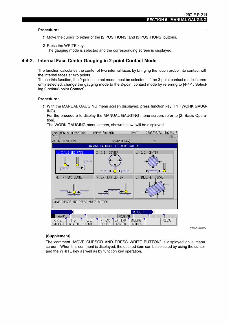
4297-E P-214SECTION 5 MANUAL GAUGING
Procedure :
1 Move the cursor to either of the [2 POSITIONS] and [3 POSITIONS] buttons.
2 Press the WRITE key.The gauging mode is selected and the corresponding screen is displayed.
4-4-2. Internal Face Center Gauging in 2-point Contact Mode
Eeoemr5s4017The function calculates the center of two internal faces by bringing the touch probe into contact withthe internal faces at two points.To use this function, the 2-point contact mode must be selected. If the 3-point contact mode is pres-ently selected, change the gauging mode to the 2-point contact mode by referring to [4-4-1. Select-ing 2-point/3-point Contact].
Procedure :
1 With the MANUAL GAUGING menu screen displayed, press function key [F1] (WORK GAUG-ING).For the procedure to display the MANUAL GAUGING menu screen, refer to [2. Basic Opera-tion].The WORK GAUGING menu screen, shown below, will be displayed.
EIOEMR5S4038R01
[Supplement]The comment “MOVE CURSOR AND PRESS WRITE BUTTON” is displayed on a menuscreen. When this comment is displayed, the desired item can be selected by using the cursorand the WRITE key as well as by function key operation.

4297-E P-215SECTION 5 MANUAL GAUGING
2 Press function key [F4] (INT END CENTER).The WORK GAUGING 4. INT END CENTER screen, shown below, is displayed.
EIOEMR5S4039R01
The following comment is displayed on the screen.“SELECT AXIS BY CURSOR AND PRESS WRITE BUTTON”
3 Select the axis (X or Y) used for gauging and press the WRITE key as instructed by the com-ment.The selected axis is displayed at “AXIS SELECT” and the cursor moves to “TOUCH POS 1”.
EIOEMR5S4040R01
The following comment is displayed on the screen.“TOUCH THE END FACE AND PRESS WRITE BUTTON”.

4297-E P-216SECTION 5 MANUAL GAUGING
4 Move the touch probe in the selected axis direction using the pulse handle to bring it into con-tact with the end face.Move the touch probe with the “x1” multiplication ratio setting for contact detection.The touch probe red LED lights when the touch probe contacts the end face.
5 At the position where contact is detected, press the WRITE key.The end face position in the presently selected coordinate system is displayed and the cursormoves to “TOUCH POS 2”.
6 Perform a similar operation to make the touch probe contact the other end face, then press theWRITE key.When position 2 is set, the cursor moves to “CENTER POS”.
EIOEMR5S4041R01
The following comment is displayed.“PRESS WRITE BUTTON”

4297-E P-217SECTION 5 MANUAL GAUGING
7 Press the WRITE key as instructed by the comment.The coordinate values of the center position are automatically displayed and the cursor movesto “ZERO OFFSET NO.”.
EIOEMR5S4042R01
The following comment is displayed.“WRITE THE WORK COORDINATE SYSTEM THE FORMS THE ZERO OFFSET”
8 Input the work coordinate system number as instructed by the comment and press the WRITEkey.The data of “TOUCH POS”, “CENTER POS”, “ZERO OFFSET” and “ACT POSIT”, with theexception of “L”, is updated to the coordinate values in the set coordinate system.When the data is set for “ZERO OFFSET NO.”, the cursor moves to “ZERO OFFSET X” and thefollowing comment is displayed.
EIOEMR5S4043R01

4297-E P-218SECTION 5 MANUAL GAUGING
“WRITE THE POSITION OF THE NEW COORDINATE”
9 Input the X and Y coordinate values of the center position between two internal faces in thenew coordinate system and press the WRITE key.The set center coordinate values, X and Y, are displayed at “CENTER POS” and the data of“TOUCH POS”, “ZERO OFFSET” and “ACT POSIT” are updated accordingly.The cursor automatically returns to “AXIS SELECT”.
EIOEMR5S4044R01
This completes the internal face center gauging operation.
10 Press function key [F8] (CLOSE).The screen returns to the WORK GAUGING menu screen.
11 Press function key [F8] (CLOSE).The screen returns to the MANUAL GAUGING MENU screen.

4297-E P-219SECTION 5 MANUAL GAUGING
4-4-3. Internal Face Center Gauging in 3-point Contact Mode
Eeoemr5s4018This function calculates the center of two internal faces by bringing the touch probe into contact withthe internal faces at three points.To use this function, the 3-point contact mode must be selected. If the 2-point contact mode is pres-ently selected, change the gauging mode to the 3-point contact mode by referring to [4-4-1. Select-ing 2-point/3-point Contact].
[Supplement]
Procedure :
1 With the MANUAL GAUGING menu screen displayed, press function key [F1] (WORK GAUG-ING).For the procedure to display the MANUAL GAUGING menu screen, refer to [2. Basic Opera-tion].The WORK GAUGING menu screen, shown below, will be displayed.
EIOEMR5S4045R01
[Supplement]
Even if the 3-point contact mode is selected, it is possible to calculate the center position by bring-ing the touch probe into contact with the internal faces at two points. For details, refer to [4-4-4.Gauging only Two Points in 3-Point Contact Mode].
The comment “MOVE CURSOR AND PRESS WRITE BUTTON” is displayed on a menuscreen. When this comment is displayed, the desired item can be selected by using the cursorand the WRITE key as well as by function key operation.

4297-E P-220SECTION 5 MANUAL GAUGING
2 Press function key [F4] (INT END CENTER).The WORK GAUGING 4. INT END CENTER screen, shown below, is displayed with the cursorpositioned at “TOUCH POS 1”.
EIOEMR5S4046R01
The following comment is displayed on the screen.“TOUCH THE END FACE AND PRESS WRITE BUTTON IF 2 POSITIONS GAUGING,SELECT AXIS”
[Supplement]
3 Move the touch probe in the selected axis direction using the pulse handle to bring it into con-tact with the internal face at position 1 (position 1 in the guide diagram).Move the touch probe with the “x1” multiplication ratio setting for contact detection.The touch probe red LED lights when the touch probe detects a contact.
4 At the position where the contact is detected, press the WRITE key.The end face position in the presently selected coordinate system is displayed and the cursormoves to “TOUCH POS 2”.The following comment is displayed.“TOUCH THE END FACE AND PRESS WRITE BUTTONIF SELECTING 2 POSITIONS GAUGING, DON’T GAUGE THIS POSITION”
To execute gauging with touch probe contact at only two points, move the cursor “AXISSELECT”, select an axis (X or Y), then move the cursor “TOUCH POS 1” again.

4297-E P-221SECTION 5 MANUAL GAUGING
5 Perform a similar operation to make the touch probe contact position 2 and position 3 (positions2 and 3 in the guide diagram).
[Supplement]1) At positions 1 and 2, gauging is executed on one internal face, and at position 3, gauging is
executed on the other internal face that is parallel to the first internal face.2) To execute this gauging operation by bringing the touch probe into contact with the internal
faces at two points, skip the contact at position 2 (TOUCH POS 2).When positions 2 and 3 are set, the cursor moves to “CENTER POS”.
EIOEMR5S4047R01
The following comment is displayed.“PRESS WRITE BUTTON”

4297-E P-222SECTION 5 MANUAL GAUGING
6 Press the WRITE key as instructed by the comment.The data is automatically displayed for “CENTER POS”, “distance between end faces (L)” and“inclination angle (β)”, then the cursor moves to “ZERO OFFSET NO.”.
EIOEMR5S4048R01
The data is obtained in the manner indicated below for each item.
The following comment is displayed.“WRITE THE WORK COORDINATE SYSTEM THE FORMS THE ZERO OFFSET”
CENTER POS: The center position between positions 1 and 3 is calculated assuming that the end faces are parallel to each other.
Distance between end faces (L):The distance between two end faces in the right angle direc-tion to the faces is calculated assuming that the inclined face gauged at positions 1 and 2 and the other face gauged at posi-tion 3 are parallel with each other.
Inclination angle (β): The angle made between the inclined face gauged at positions 1 and 2, and the X-axis is calculated.

4297-E P-223SECTION 5 MANUAL GAUGING
7 Input the work coordinate system number as instructed by the comment and press the WRITEkey.The input number is displayed at “ZERO OFFSET NO.” and the cursor moves to “ZERO OFF-SET” data position.
EIOEMR5S4049R01
The following comment is displayed.“WRITE THE POSITION OF THE NEW COORDINATE”
8 Input the X and Y coordinate values of the center position between two end faces in the newcoordinate system and press the WRITE key.The set center coordinate values, X and Y, are displayed at “CENTER POS” and the data of“TOUCH POS”, “ZERO OFFSET” and “ACT POSIT” are updated accordingly.The cursor automatically returns to “AXIS SELECT”.
EIOEMR5S4050R01

4297-E P-224SECTION 5 MANUAL GAUGING
This completes the internal face center gauging (3-point contact mode) operation.
9 Press function key [F8] (CLOSE).The screen returns to the WORK GAUGING menu screen.
10 Press function key [F8] (CLOSE).The screen returns to the MANUAL GAUGING MENU screen.
4-4-4. Gauging only Two Points in 3-Point Contact ModeEeoemr5s4019To obtain the center position by bringing the touch probe into contact at only two points after select-
ing the 3-point contact mode, the operation procedure differs from the normal gauging operation inthe following points.
• Selection of an axis is necessary.
• Contact detection is not carried out at position 2 but must be carried out at positions 1 and 3.
• “Center position”, “distance between end faces” and “inclination angle” are calculated as indi-cated below.
[Supplement]
For details of operation, refer to [4-4-3. Internal Face Center Gauging in 3-point Contact Mode].
Center position: The center between positions 1 and 3
Distance between end faces (L):Distance between positions 1 and 3
Inclination angle (β): If the X-axis is selected for “AXIS SELECT”, this angle is 90°.If the Y-axis is selected for “AXIS SELECT”, this angle is 0°.
To execute gauging at only two points although the 3-point contact mode is selected, no data mustbe displayed for “TOUCH POS 2” (immediately after the data is cleared or the start of this gaugingoperation).

4297-E P-225SECTION 5 MANUAL GAUGING
4-5. External Faces Center GaugingEeoemr5s4020The center gauging function for two external faces (projection center gauging function) is used to set
the zero point at the center of the two external faces.The function provides two modes of operation to calculate the center - 2-point contact and 3-pointcontact.
4-5-1. Selecting 2-point/3-point Contact
Eeoemr5s4021Which of the gauging modes is used can be selected by parameter setting or by using the buttonson the screen.
• Selection by parameterTo select the contact mode by parameter setting, use CNC optional parameter (bit) No. 48, bit 3.Without check mark: 2-point contactWith check mark: 3-point contact
[Supplement]
• Selection with buttonsFor selecting the gauging mode, the [2 POSITIONS] and [3 POSITIONS] buttons are providedon the screen. Select the desired gauging pattern by pressing the corresponding button.
EIOEMR5S4051R01
Procedure :
1 Move the cursor to either of the [2 POSITIONS] and [3 POSITIONS] buttons.
2 Press the WRITE key.The gauging mode is selected and the corresponding screen is displayed.
If the gauging mode is selected by parameter, the screen display is not changed unless thescreen is closed and redisplayed.

4297-E P-226SECTION 5 MANUAL GAUGING
4-5-2. External Face Center Gauging in 2-point Contact Mode
Eeoemr5s4022The function calculates the center of two external faces by bringing the touch probe into contact withthe external faces at two points.To use this function, the 2-point contact mode must be selected. If the 3-point contact mode is pres-ently selected, change the gauging mode to the 2-point contact mode by referring to [4-5-1. Select-ing 2-point/3-point Contact].
Procedure :
1 With the MANUAL GAUGING menu screen displayed, press function key [F1] (WORK GAUG-ING).For the procedure to display the MANUAL GAUGING menu screen, refer to [2. Basic Opera-tion].The WORK GAUGING menu screen, shown below, will be displayed.
EIOEMR5S4052R01
[Supplement]The comment “MOVE CURSOR AND PRESS WRITE BUTTON” is displayed on a menuscreen. When this comment is displayed, the desired item can be selected by using the cursorand the WRITE key as well as by function key operation.

4297-E P-227SECTION 5 MANUAL GAUGING
2 Press function key [F5] (EXT END CENTER).The WORK GAUGING 5. EXT END CENTER screen, shown below, is displayed.
EIOEMR5S4053R01
The following comment is displayed on the screen.“SELECT AXIS BY CURSOR AND PRESS WRITE BUTTON”
3 Select the axis (X or Y) used for gauging and press the WRITE key as instructed by the com-ment.The selected axis is displayed at “AXIS SELECT” and the cursor moves to “TOUCH POS 1”.
EIOEMR5S4054R01
The following comment is displayed on the screen.“TOUCH THE END FACE AND PRESS WRITE BUTTON”.

4297-E P-228SECTION 5 MANUAL GAUGING
4 Move the touch probe in the selected axis direction using the pulse handle to bring it into con-tact with the end face.Move the touch probe with the “x1” multiplication ratio setting for contact detection.The touch probe red LED lights when the touch probe contacts the end face.
5 At the position where contact is detected, press the WRITE key.The end face position in the presently selected coordinate system is displayed and the cursormoves to “TOUCH POS 2”.
6 Perform a similar operation to make the touch probe contact the other end face, then press theWRITE key.When the position 2 is set, the cursor moves to “CENTER POS”.
EIOEMR5S4055R01
The following comment is displayed.“PRESS WRITE BUTTON”

4297-E P-229SECTION 5 MANUAL GAUGING
7 Press the WRITE key as instructed by the comment.The coordinate values of the center position are automatically displayed and the cursor movesto “ZERO OFFSET NO.”.
EIOEMR5S4056R01
The following comment is displayed.“WRITE THE WORK COORDINATE SYSTEM THE FORMS THE ZERO OFFSET”
8 Input the work coordinate system number as instructed by the comment and press the WRITEkey.The data of “TOUCH POS”, “CENTER POS”, “ZERO OFFSET” and “ACT POSIT”, with anexception of “L”, is updated to the coordinate values in the set coordinate system.When the data is set for “ZERO OFFSET NO.”, the cursor moves to “ZERO OFFSET X”,
EIOEMR5S4057R01

4297-E P-230SECTION 5 MANUAL GAUGING
The following comment is displayed.“WRITE THE POSITION OF THE NEW COORDINATE”
9 Input the X and Y coordinate values of the center position between two external faces in thenew coordinate system and press the WRITE key.The set center coordinate values, X and Y, are displayed at “CENTER POS” and the data of“TOUCH POS”, “ZERO OFFSET” and “ACT POSIT” are updated accordingly.The cursor automatically returns to “AXIS SELECT”.
EIOEMR5S4058R01
This completes the external face center gauging operation.
10 Press function key [F8] (CLOSE).The screen returns to the WORK GAUGING menu screen.
11 Press function key [F8] (CLOSE).The screen returns to the MANUAL GAUGING MENU screen.
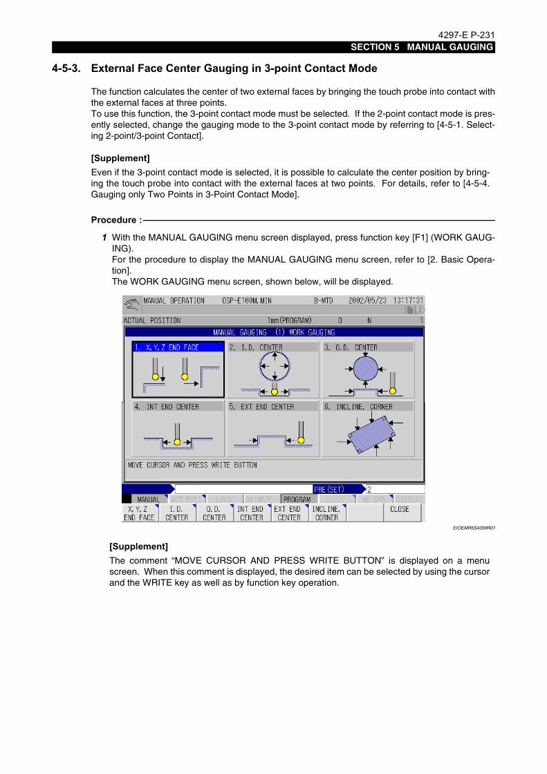
4297-E P-231SECTION 5 MANUAL GAUGING
4-5-3. External Face Center Gauging in 3-point Contact Mode
Eeoemr5s4023The function calculates the center of two external faces by bringing the touch probe into contact withthe external faces at three points.To use this function, the 3-point contact mode must be selected. If the 2-point contact mode is pres-ently selected, change the gauging mode to the 3-point contact mode by referring to [4-5-1. Select-ing 2-point/3-point Contact].
[Supplement]
Procedure :
1 With the MANUAL GAUGING menu screen displayed, press function key [F1] (WORK GAUG-ING).For the procedure to display the MANUAL GAUGING menu screen, refer to [2. Basic Opera-tion].The WORK GAUGING menu screen, shown below, will be displayed.
EIOEMR5S4059R01
[Supplement]
Even if the 3-point contact mode is selected, it is possible to calculate the center position by bring-ing the touch probe into contact with the external faces at two points. For details, refer to [4-5-4.Gauging only Two Points in 3-Point Contact Mode].
The comment “MOVE CURSOR AND PRESS WRITE BUTTON” is displayed on a menuscreen. When this comment is displayed, the desired item can be selected by using the cursorand the WRITE key as well as by function key operation.

4297-E P-232SECTION 5 MANUAL GAUGING
2 Press function key [F5] (EXT END CENTER).The WORK GAUGING 5. EXT END CENTER screen, shown below, is displayed with the cur-sor positioned at “TOUCH POS 1”.
EIOEMR5S4060R01
The following comment is displayed on the screen.“TOUCH THE END FACE AND PRESS WRITE BUTTON IF 2 POSITIONS GAUGING, SELECT AXIS”
[Supplement]
3 Move the touch probe in the selected axis direction using the pulse handle to bring it into con-tact with the internal face at position 1 (position 1 in the guide diagram).Move the touch probe with the “x1” multiplication ratio setting for contact detection.The touch probe red LED lights when the touch probe detects a contact.
4 At the position where the contact is detected, press the WRITE key.The end face position in the presently selected coordinate system is displayed and the cursormoves to “TOUCH POS 2”.The following comment is displayed.“TOUCH THE END FACE AND PRESS WRITE BUTTON IF SELECTING 2 POSITIONS GAUGING, DON’T GAUGE THIS POSITION”
To execute gauging by making the touch probe contact only at two points, move the cursor“AXIS SELECT”, select an axis (X or Y), then move the cursor “TOUCH POS 1” again.

4297-E P-233SECTION 5 MANUAL GAUGING
5 Perform a similar operation to make the touch probe contact position 2 and position 3 (positions2 and 3 in the guide diagram).
[Supplement]1) At positions 1 and 2, gauging is executed on one internal face, and at position 3, gauging is
executed on the other internal face that is parallel to the first internal face.2) To execute this gauging operation by bringing the touch probe into contact with the external
faces at two points, skip the contact at position 2 (TOUCH POS 2).When positions 2 and 3 are set, the cursor moves to “CENTER POS”.
EIOEMR5S4061R01
The following comment is displayed“PRESS WRITE BUTTON”

4297-E P-234SECTION 5 MANUAL GAUGING
6 Press the WRITE key as instructed by the comment.The data is automatically displayed for “CENTER POS”, “distance between end faces (L)” and“inclination angle (b)”, then the cursor moves to “ZERO OFFSET NO.”.
EIOEMR5S4062R01
The data for each item is obtained in the manner indicated below.
The following comment is displayed.“WRITE THE WORK COORDINATE SYSTEM THE FORMS THE ZERO OFFSET”
CENTER POS: The center position between positions 1 and 3 is calculated assuming that the end faces are parallel to each other.
Distance between end faces (L): The distance between two end faces in the right angle direc-tion to the faces is calculated assuming that the inclined face gauged at positions 1 and 2 and the other face gauged at position 3 are parallel with each other.
Inclination angle (β): The angle made between the inclined face gauged at posi-tions 1 and 2, and the X-axis is calculated.

4297-E P-235SECTION 5 MANUAL GAUGING
7 Input the work coordinate system number as instructed by the comment and press the WRITEkey.The input number is displayed at “ZERO OFFSET NO.” and the cursor moves to “ZERO OFF-SET” data position.
EIOEMR5S4063R01
The following comment is displayed.“WRITE THE POSITION OF THE NEW COORDINATE”
8 Input the X and Y coordinate values of the center position between two end faces in the newcoordinate system and press the WRITE key.The set center coordinate values, X and Y, are displayed at “CENTER POS” and the data of“TOUCH POS”, “ZERO OFFSET” and “ACT POSIT” are updated accordingly.The cursor automatically returns to “AXIS SELECT”.
EIOEMR5S4064R01

4297-E P-236SECTION 5 MANUAL GAUGING
This completes the external face center gauging (3-point contact mode) operation.
9 Press function key [F8] (CLOSE).The screen returns to the WORK GAUGING menu screen.
10 Press function key [F8] (CLOSE).The screen returns to the MANUAL GAUGING MENU screen.
4-5-4. Gauging only Two Points in 3-Point Contact ModeEeoemr5s4024To obtain the center position by bringing the touch probe into contact only at two points after select-
ing the 3-point contact mode, the operation procedure differs from the normal gauging operation inthe following points.
• Selection of an axis is necessary.
• Contact detection is not carried out at position 2 but must be carried out at positions 1 and 3.
• “Center position”, “distance between end faces” and “inclination angle” are calculated as indi-cated below.
[Supplement]
For details of operation, refer to [4-5-3. External Face Center Gauging in 3-point Contact Mode].
Center position: The center between positions 1 and 3
Distance between end faces (L): Distance between positions 1 and 3
Inclination angle (β): If X-axis is selected for “AXIS SELECT”, this angle is 90°.If Y-axis is selected for “AXIS SELECT”, this angle is 0°.
To execute gauging only at two points although the 3-point contact mode is selected, no data mustbe displayed for “TOUCH POS 2” (immediately after the data is cleared or the start of this gaugingoperation).

4297-E P-237SECTION 5 MANUAL GAUGING
4-6. Inclination and Corner GaugingEeoemr5s4025This function is used to determine the zero point on the X- and Y-axis for workpieces that are not
mounted parallel to these axes.Note that although the zero offset is automatically executed for the X- and Y-axis, zero offset for incli-nation is not carried out automatically and therefore the data must be reflected to the part programas necessary.
Procedure :
1 With the MANUAL GAUGING menu screen displayed, press function key [F1] (WORK GAUG-ING).For the procedure to display the MANUAL GAUGING menu screen, refer to [2. Basic Opera-tion].The WORK GAUGING menu screen, shown below, will be displayed.
EIOEMR5S4065R01
[Supplement]The comment “MOVE CURSOR AND PRESS WRITE BUTTON” is displayed on a menuscreen. When this comment is displayed, the desired item can be selected by using the cursorand the WRITE key as well as by function key operation.

4297-E P-238SECTION 5 MANUAL GAUGING
2 Press function key [F2] (INCLINE, CORNER).The WORK GAUGING 6. INCLINE, CORNER screen is displayed.
EIOEMR5S4066R01
The following comment is displayed.“SELECT CORNER BY CURSOR AND PRESS WRITE BUTTON”
3 Select the corner where gauging is to be executed from “GAUGING CORNER (A, B, C, D)” asinstructed by the comment and press the WRITE key.The colors of the arrow symbol, and the related number and corner name automaticallychange.
EIOEMR5S4067R01

4297-E P-239SECTION 5 MANUAL GAUGING
The direction of gauging at a contact detection position differs depending on the selected cor-ner as shown below.
The cursor moves to “TOUCH POS 1”.
EIOEMR5S4068R01
The following comment is displayed.“MAKE A TOUCH AND PRESS WRITE BUTTON”
4 Bring the touch probe into contact with the workpiece at position 1 (position 1 in the guide dia-gram) using the pulse handle as instructed by the comment.Feed the touch probe with the “x1” multiplication ratio setting for contact detection.The touch probe red LED lights when the touch probe detects a contact.
5 At the position where the contact is detected, press the WRITE key.The corner position in the presently selected coordinate system is displayed and the cursormoves to “TOUCH POS 2”.
GAUGING CORNER Contact Position 1 Contact Position 2 Contact Position 3
CORNER A Y+ Y+ X+
CORNER B Y+ Y+ X-
CORNER C Y- Y- X-
CORNER D Y- Y- X+

4297-E P-240SECTION 5 MANUAL GAUGING
6 Execute gauging at contact positions 2 and 3 (positions 2 and 3 in the guide drawing) using thesame operation.The cursor moves to “CORNER POS/ANG”.
EIOEMR5S4069R01
The following comment is displayed.“PRESS WRITE BUTTON”
7 Press the WRITE key as instructed by the comment.The data of the corner, and the angle, are automatically displayed and the cursor moves to“ZERO OFST NO.”
EIOEMR5S4070R01
The following comment is displayed.“WRITE THE WORK COORDINATE SYSTEM THE FORMS THE ZERO OFFSET”
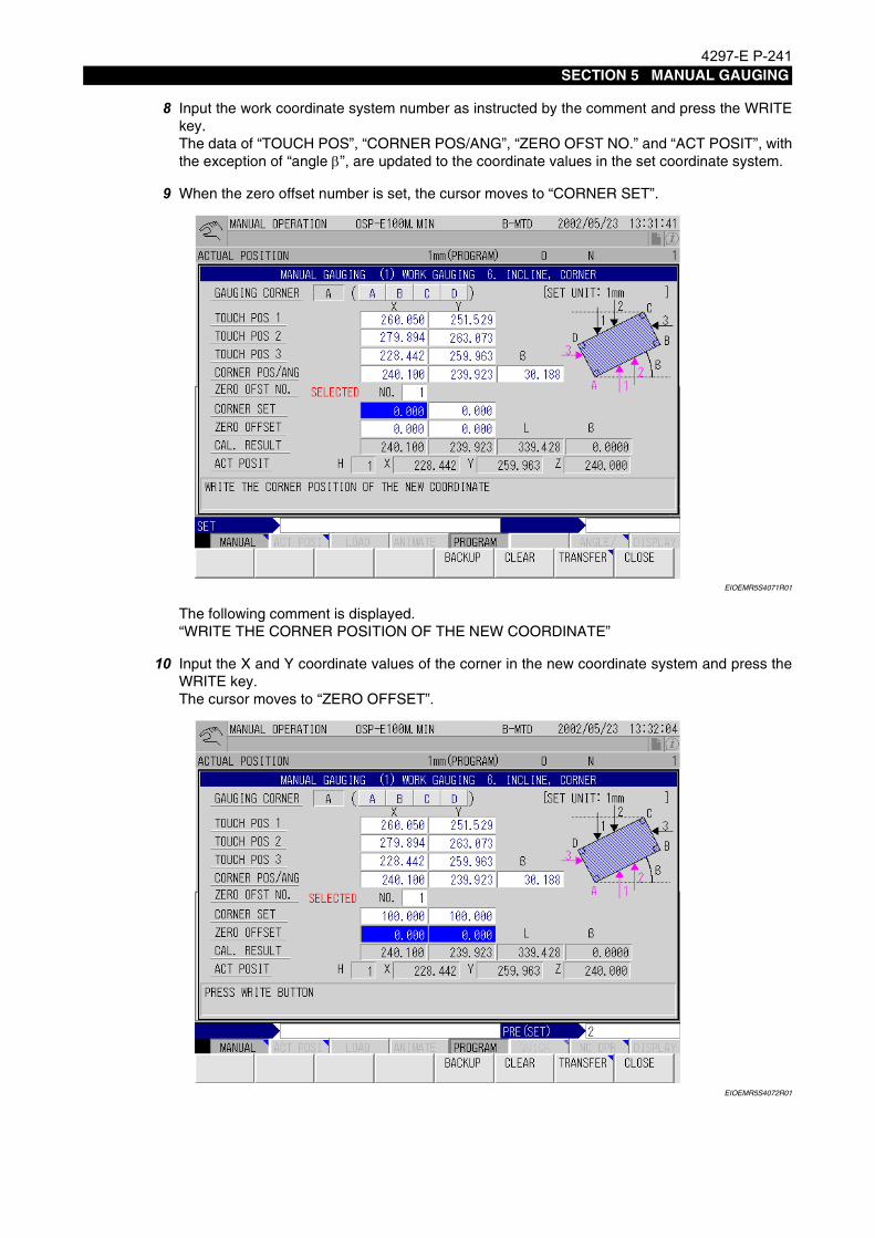
4297-E P-241SECTION 5 MANUAL GAUGING
8 Input the work coordinate system number as instructed by the comment and press the WRITEkey.The data of “TOUCH POS”, “CORNER POS/ANG”, “ZERO OFST NO.” and “ACT POSIT”, withthe exception of “angle β”, are updated to the coordinate values in the set coordinate system.
9 When the zero offset number is set, the cursor moves to “CORNER SET”.
EIOEMR5S4071R01
The following comment is displayed.“WRITE THE CORNER POSITION OF THE NEW COORDINATE”
10 Input the X and Y coordinate values of the corner in the new coordinate system and press theWRITE key.The cursor moves to “ZERO OFFSET”.
EIOEMR5S4072R01

4297-E P-242SECTION 5 MANUAL GAUGING
The following comment is displayed.“PRESS WRITE BUTTON”
11 Press the WRITE key as instructed by the comment.The data of “TOUCH POS”, “CORNER POS/ANG”, “ZERO OFST NO.” and “ACT POSIT” isautomatically updated and the cursor returns to “GAUGING CORNER”.
EIOEMR5S4073R01
This completes the inclination/corner gauging operation.
12 Press function key [F8] (CLOSE).The screen returns to the WORK GAUGING menu screen.
13 Press function key [F8] (CLOSE).The screen returns to the MANUAL GAUGING MENU screen.
[Supplement]1) The function assumes that angles at a corner (A, B, C, D) are right angles.2) The angle value (β) is the angle made between the X-axis and the line defined by contact detec-
tion positions 1 and 2.3) The angle value (β) displayed at “β” of “CAL. RESULT” is registered in system common vari-
ables VS65.4) The value set for VS65 cannot be directly displayed on the screen. It is cleared when the power
is turned off.To check the value set for VS65 or to retain the value after turning the power off, perform the fol-lowing steps.

4297-E P-243SECTION 5 MANUAL GAUGING
Procedure :
1 Select the MDI mode.
2 Input “VC✽✽=VS65”.Input a normal common variable number for “✽✽”.
3 Press the WRITE key.
4 Press the CYCLE START button.The value set for VS65 is set at VC✽✽.Once the value is set for a common variable, the value can be checked by displaying theparameter setting screen.
NOTICEIn a program, specify the commands like “G11 P=VC✽✽”.

4297-E P-244SECTION 5 MANUAL GAUGING
5. Tool Length GaugingEeoemr5s4026The tool length gauging function is used to set the tool length offset data.
Procedure :
1 In the state the MANUAL GAUGING MENU screen is displayed, press function key [F2] (TOOLLENGTH GAUGING).For the procedure for displaying the MANUAL GAUGING MENU screen, refer to [2. BasicOperation].The TOOL LENGTH GAUGING screen, shown below, will be displayed.
EIOEMR5S4074R01
[Supplement]
The following comment is displayed.“WRITE THE NEXT GAUGING TOOL NUMBER BY SET AND START ATC 1 CYCLE”
2 Input the tool number of the tool to be gauged to “NEXT TOOL” and press the WRITE key asinstructed by the comment.
The comment “MOVE CURSOR AND PRESS WRITE BUTTON” is displayed on a menuscreen. When this comment is displayed, the desired item can be selected by using the cursorand the WRITE key as well as by function key operation.

4297-E P-245SECTION 5 MANUAL GAUGING
3 Press the [1 CYCLE START] button on the ATC operation panel to mount the tool to be gaugedin the spindle.The tool number of the tool mounted in the spindle is displayed at “ACT TOOL”.
EIOEMR5S4075R01
The cursor moves to “TOOL-L OFST NO.” and the following comment is displayed.“WRITE THE TOOL LENGTH OFFSET NUMBER”
4 Input the tool length offset number as instructed by the comment and press the WRITE key.The cursor moves to “TOOL-L OFFSET”.
EIOEMR5S4076R01
The following comment is displayed.“MAKE A TOUCH AND PRESS WRITE BUTTON”.

4297-E P-246SECTION 5 MANUAL GAUGING
5 Bring the tool into contact with the touch sensor, as instructed by the comment, by operatingthe pulse handle.Move the tool with the “x1” multiplication ratio setting for contact detection.The touch probe red LED lights when contact is detected.
6 At the position where contact is detected, press the WRITE key.The tool length offset data is displayed.This completes the tool length gauging operation when the tool offset data of other tools is notmeasured.To execute the tool length gauging cycle for other tools, proceed to the next step.
7 Move the cursor to “ACT TOOL”.
8 Input the tool number to “ACT TOOL” and press the WRITE key.The cursor moves to “POT NO.” and the following comment is displayed.“WRITE THE RETURN DESTINATION POT NUMBER BY SET (✽ WHEN NOT SET)”
9 Input the return tool pot number or “✽” as instructed by the comment and press the WRITE key.When the return pot number is set, pressing the [1 CYCLE START] button on the ATC opera-tion panel causes the tool to be returned to the specified pot.If an attempt is made to call another tool by setting its number at “NEXT TOOL” while a returnpot number is set at “POT NO.”, an alarm occurs and the following alarm message is displayedon the screen.“5266 Pot command exist”.To avoid this, input “✽” for “POT NO.” and press the WRITE key. This causes “NA” to be set for“POT NO.”, allowing the next tool set for “NEXT TOOL” to be called.After calling the next tool, repeat steps 4) to 9) for all tools for which the tool length offset datashould be set.
10 Press function key [F8] (CLOSE).The screen returns to the MANUAL GAUGING MENU screen.
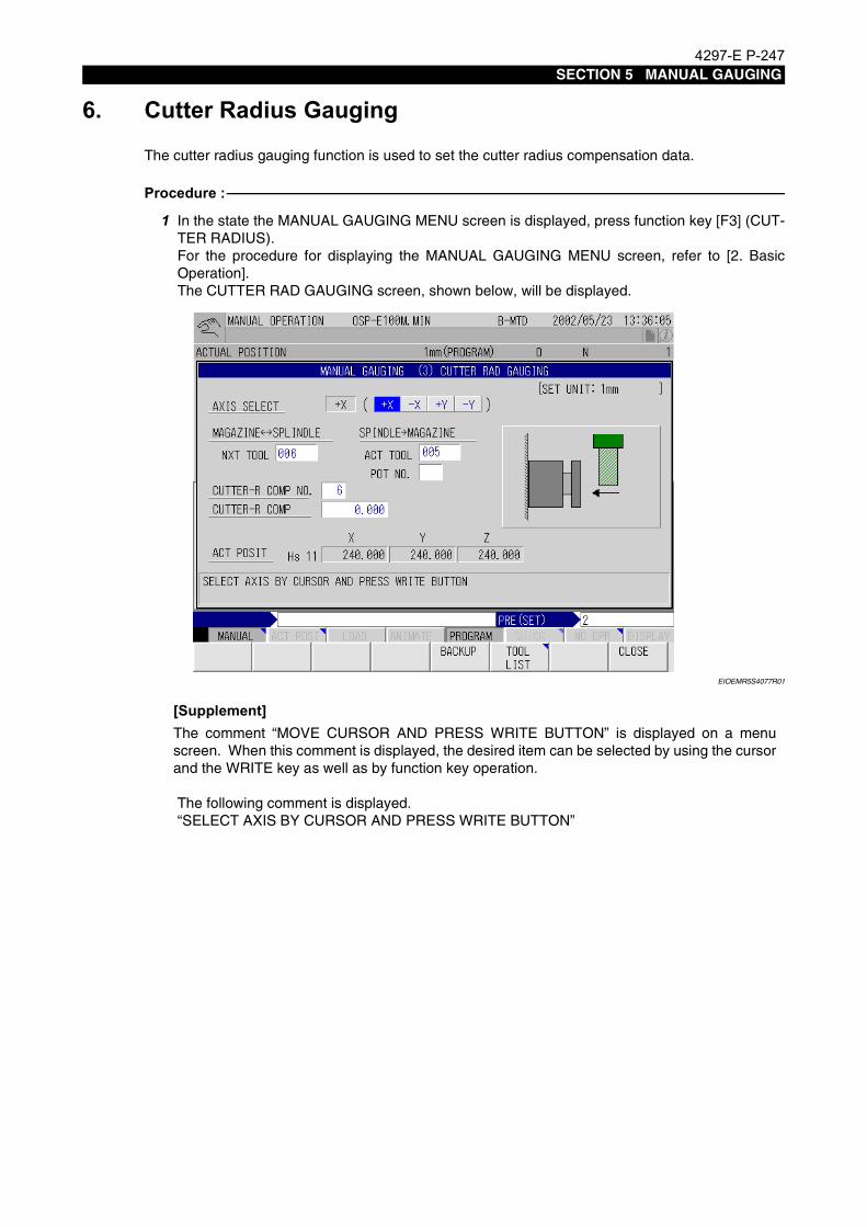
4297-E P-247SECTION 5 MANUAL GAUGING
6. Cutter Radius GaugingEeoemr5s4027The cutter radius gauging function is used to set the cutter radius compensation data.
Procedure :
1 In the state the MANUAL GAUGING MENU screen is displayed, press function key [F3] (CUT-TER RADIUS).For the procedure for displaying the MANUAL GAUGING MENU screen, refer to [2. BasicOperation].The CUTTER RAD GAUGING screen, shown below, will be displayed.
EIOEMR5S4077R01
[Supplement]
The following comment is displayed.“SELECT AXIS BY CURSOR AND PRESS WRITE BUTTON”
The comment “MOVE CURSOR AND PRESS WRITE BUTTON” is displayed on a menuscreen. When this comment is displayed, the desired item can be selected by using the cursorand the WRITE key as well as by function key operation.

4297-E P-248SECTION 5 MANUAL GAUGING
2 Select the direction of gauging (+X, -X, +Y, -Y) by moving the cursor to the desired choice, asinstructed by the comment, and press the WRITE key.
EIOEMR5S4078R01
Fig.5-1 Selecting the Gauging Axis
The cursor moves to “NEXT TOOL” and the following message is displayed.“WRITE THE NEXT GAUGING TOOL NUMBER BY SET AND START ATC 1 CYCLE”
3 Input the tool number of the tool to be gauged at “NEXT TOOL” and press the WRITE key asinstructed by the comment.
4 Press the [1 CYCLE START] button on the ATC operation panel to mount the tool to be gaugedin the spindle.
5 The spindle is orientated.The cursor moves to “CUTR-R COMP NO.” and the following comment is displayed.“WRITE THE CUTTER RADIUS COMPENSATION NUMBER”
6 Input the cutter radius compensation number as instructed by the comment and press theWRITE key.The cursor moves to “CUTR-R COMP”.
EIOEMR5S4079R01
The following comment is displayed.“MAKE A TOUCH AND PRESS WRITE BUTTON”.
-X
+Y
-Y
+X

4297-E P-249SECTION 5 MANUAL GAUGING
7 Bring the tool into contact with the touch sensor as instructed by the comment by operating thepulse handle.Move the tool with the “x1” multiplication ratio setting for contact detection.The touch probe red LED lights when contact is detected.
8 At the position where contact is detected, press the WRITE key.The cutter radius compensation data is displayed.This completes the cutter radius gauging operation when the cutter radius compensation dataof other tools is not measured.
9 To execute the cutter radius gauging cycle for other tools, repeat the gauging operation stepsindicated above for all tools for which the cutter radius compensation data is to be set.This completes the cutter radius gauging operation.
10 Press function key [F8] (CLOSE).The screen returns to the MANUAL GAUGING MENU screen.For the procedure for setting "ACT TOOL" and "POT NO." refer to [5. Tool Length Gauging].

4297-E P-250SECTION 5 MANUAL GAUGING
7. Comparison and Calculation of Gauging ResultsEeoemr5s4028In conventional gauging operation, absolute gauging results are obtained in the work coordinate
system currently selected. The new manual gauging function allows gauging results to be savedusing the data transfer function and to perform gauging while comparing and calculating gaugingresults of various gauging cycles.Any combination of gauging cycles, for example “INCLINE, CORNER” and “INT END CENTER”, “IDGAUGING” and “OD GAUGING”, and others, is allowed as long as the results of gauging (to beexplained later) remain on the WORK GAUGING screen. It is also possible to display the results ofcomparison/calculation (angle, distance, coordinate value, etc.) WORK GAUGING screens.
EIOEMR5S4080R01
7-1. Transferring Gauging ResultsEeoemr5s4029The procedure for transferring results of gauging after the completion of a gauging cycle is
described below.
Procedure :
1 After the completion of a work gauging cycle, press function key [F7] (TRANSFER) on theWORK GAUGING screen. A comment such as the one indicated below will be displayed.“INT CENTER (H0) X162.475 INT CENTER (H0) Y147.078 INT CENTER β45.000 THESEARE PREVIOUS GAUGING RESULTS WHICH RESULT DO YOU TRANSFER?”The term such as “INT CENTER” given in the comment represents the mode of the gaugingcycle that was executed to obtain the result.“INT CENTER (H0) X162.475” in the comment shown in the example screen above means thatthe data that was transferred is the X-axis gauging result obtained in the internal face centergauging operation and that the value is “162.475” in the machine coordinate system (H0).The comment displayed on the screen includes one of the following terms, which indicate thegauging mode used.
• “END FACE”: Data transferre as the result of end face gauging operation
• “INSIDE DIA”: Data transferred as the result of the I.D. gauging operation

4297-E P-251SECTION 5 MANUAL GAUGING
• “OUTSIDE DIA”: Data transferred as the result of the O.D. gauging operation
• “INT CENTER”: Data transferred as the result of the internal end face center gaugingoperation
• “EXT CENTER”: Data transferred as the result of the external end face center gaugingoperation
• “CORNER”: Data transferred as the result of inclination/corner gauging operation
[Supplement]
2 In this state, select the data to be transferred by pressing the corresponding function key.
• [F1] POSIT: Transfers the position data.
• [F2] ANGLE: Transfers the angle data.
• [F3] POSIT & ANGLE: Transfers the position and angle data.
If no data is to be transferred, press function key [F8] (CANCEL).If any of function keys [F1] (POSIT), [F2] (ANGLE) and [F3] (POSIT & ANGLE) is pressed, thecorresponding data obtained in the latest gauging cycle is transferred and stored in the CNCmemory.The actual data to be transferred depends on the executed work gauging cycle. See the tablebelow for the relationship between a work gauging cycle and the data to be transferred.
If function key [F3] (POSIT & ANGLE) is pressed, both the kinds of data selected by [F1](POSIT) and [F2] (ANGLE) are transferred.If any of these function keys ([F1], [F2], [F3]) is pressed before a gauging cycle is completed,no data is transferred and the following comment is displayed on the screen. The previoustransferred data remains.“NO GAUGING RESULT! CONTINUE GAUGING”
3 If the comment indicated above is displayed, press function key [F8] (CANCEL). This cancels data transfer mode and allows the operation to be continued.
The X and Y data, among the transferred data, are coordinate values in the machine coordi-nate system (H0).Data “β” represents an angle value.
Work Gauging Cycle Transferred Data with [F1] Transferred Data with [F2]
End face gauging (X, Y, Z) End face position 0
I.D. center I.D. center position 0
O.D. center O.D. center position 0
Center between two internal faces(2-point contact mode)
Center position between two internal faces
(only for the selected axis)0
Center between two internal faces(3-point contact mode)
Center position between two internal faces
End face angle
Center between two external faces(2-point contact mode)
Center position between two external faces
(only for the selected axis)0
Center between two external faces(3-point contact mode)
Center position between two external faces
End face angle
Inclination/corner Corner position Workpiece angle

4297-E P-252SECTION 5 MANUAL GAUGING
7-2. Comparison with Gauging DataEeoemr5s4030Data obtained in other gauging cycles is converted into the values in a pseudo local coordinate sys-
tem on the basis of the transferred data. Angle, distance, and coordinate values (with reference tothe zero point in the local coordinate system) are displayed on each WORK GAUGING screen.Note that calculation results may not be calculated and displayed depending on the type of gaugingoperation, as indicated in the table below.
: Calculation results are displayed.—: Calculation results are not displayed.
7-3. Example of Calculation Results DisplayEeoemr5s4031How the calculation results are displayed is described below.
Assume workpiece A shown below is set on the table with a certain angle to the machine coordinatesystem. The following is the procedure to obtain the distance between the reference corner positionand the center of hole “a”, and coordinate values of the center of hole “a” in the xy coordinate sys-tem (pseudo local coordinate system).
EIOEMR5S4081R01
Gauging Operation Calculation
End face gauging —
I.D. center
O.D. center
Center between two internal faces (2 points)
—
Center between two internal faces (3 points)
Center between two external faces (2 points)
—
Center between two external faces (3 points)
Inclination/corner
Workpiece AHole "a"
75 150
Reference corner position
(xm, ym)........Machine coordinate system
ym
0 xm
x
y
(x, y).............Pseudo local coordinate system
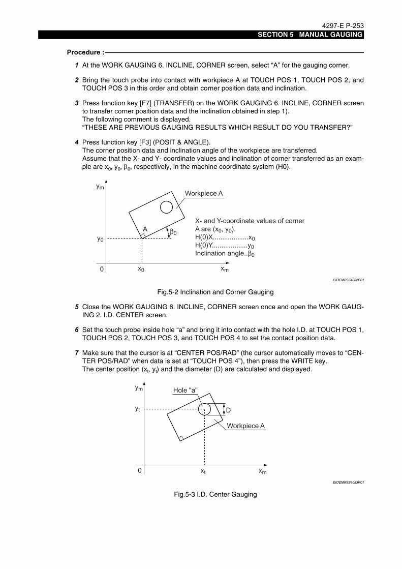
4297-E P-253SECTION 5 MANUAL GAUGING
Procedure :
1 At the WORK GAUGING 6. INCLINE, CORNER screen, select “A” for the gauging corner.
2 Bring the touch probe into contact with workpiece A at TOUCH POS 1, TOUCH POS 2, andTOUCH POS 3 in this order and obtain corner position data and inclination.
3 Press function key [F7] (TRANSFER) on the WORK GAUGING 6. INCLINE, CORNER screento transfer corner position data and the inclination obtained in step 1).The following comment is displayed.“THESE ARE PREVIOUS GAUGING RESULTS WHICH RESULT DO YOU TRANSFER?”
4 Press function key [F3] (POSIT & ANGLE).The corner position data and inclination angle of the workpiece are transferred.Assume that the X- and Y- coordinate values and inclination of corner transferred as an exam-ple are x0, y0, β0, respectively, in the machine coordinate system (H0).
EIOEMR5S4082R01
Fig.5-2 Inclination and Corner Gauging
5 Close the WORK GAUGING 6. INCLINE, CORNER screen once and open the WORK GAUG-ING 2. I.D. CENTER screen.
6 Set the touch probe inside hole “a” and bring it into contact with the hole I.D. at TOUCH POS 1,TOUCH POS 2, TOUCH POS 3, and TOUCH POS 4 to set the contact position data.
7 Make sure that the cursor is at “CENTER POS/RAD” (the cursor automatically moves to “CEN-TER POS/RAD” when data is set at “TOUCH POS 4”), then press the WRITE key.The center position (xt, yt) and the diameter (D) are calculated and displayed.
EIOEMR5S4083R01
Fig.5-3 I.D. Center Gauging
Workpiece A
X- and Y-coordinate values of corner A are (x0, y0).H(0)X...................x0H(0)Y...................y0Inclination angle..β0
ym
y0
0 x0 xm
A β0
Workpiece A
ym
yt
0 xt xm
Hole "a"
D

4297-E P-254SECTION 5 MANUAL GAUGING
The X- and Y-coordinate values (xt, yt) of the center of hole “a” will be displayed at the calcula-tion result display area on the screen. These coordinate values are calculated on the basis ofthe corner position data (x0, y0) transferred in step 5) above and are expressed as coordinatevalues in the local coordinate system (x, y) which is obtained by rotating the machine coordi-nate system (xm, ym) by transferred angle data β.The distance to the center calculated in the I.D. gauging is obtained at the same time and dis-played on the screen.
EIOEMR5S4084R01
Fig.5-4 Local Coordinate System after Comparison/Calculation
The calculation result display area shows the following data.
NOTICE
CAL. RESULT X: The distance between the reference point (x0, y0) and the center of hole “a” along the X-axis in the local coordinate system (x, y).
CAL. RESULT Y: The distance between the reference point (x0, y0) and the center of hole “a” along the Y-axis in the local coordinate system (x, y).
CAL. RESULT L: The distance between the reference point (x0, y0) and the center of hole “a”.
CAL. RESULT β: The angle formed between the X-axis and segment L in the local coordinate system.
Angle β displayed at CAL. RESULT β is completely different from angle β which is obtained ingauging operation and is transferred.
Workpiece Aym
y0
0 x0 xm
Hole "a"
y
x
LRotation by β
Reference corner position
15075
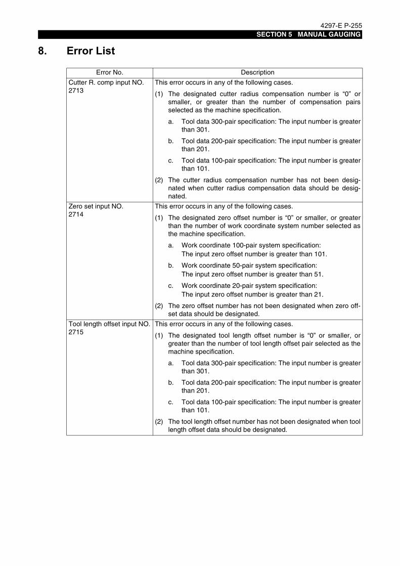
4297-E P-255SECTION 5 MANUAL GAUGING
8. Error ListEeoemr5s4032Error No. Description
Cutter R. comp input NO.2713
This error occurs in any of the following cases.
(1) The designated cutter radius compensation number is “0” orsmaller, or greater than the number of compensation pairsselected as the machine specification.
a. Tool data 300-pair specification: The input number is greaterthan 301.
b. Tool data 200-pair specification: The input number is greaterthan 201.
c. Tool data 100-pair specification: The input number is greaterthan 101.
(2) The cutter radius compensation number has not been desig-nated when cutter radius compensation data should be desig-nated.
Zero set input NO.2714
This error occurs in any of the following cases.
(1) The designated zero offset number is “0” or smaller, or greaterthan the number of work coordinate system number selected asthe machine specification.
a. Work coordinate 100-pair system specification: The input zero offset number is greater than 101.
b. Work coordinate 50-pair system specification: The input zero offset number is greater than 51.
c. Work coordinate 20-pair system specification:The input zero offset number is greater than 21.
(2) The zero offset number has not been designated when zero off-set data should be designated.
Tool length offset input NO.2715
This error occurs in any of the following cases.
(1) The designated tool length offset number is “0” or smaller, orgreater than the number of tool length offset pair selected as themachine specification.
a. Tool data 300-pair specification: The input number is greaterthan 301.
b. Tool data 200-pair specification: The input number is greaterthan 201.
c. Tool data 100-pair specification: The input number is greaterthan 101.
(2) The tool length offset number has not been designated when toollength offset data should be designated.

4297-E P-256SECTION 5 MANUAL GAUGING
Set data limit over2716
This error occurs in any of the following cases (Items 3 and 4 apply when the interactive gauging function is used).
(1) When designating the REF ring diameter, the input data is out-side the range 0 to 1000.000.
(2) When designating the reference tool diameter, the input data isoutside the range 0 to 1000.000.
(3) When designating the Z-axis upward stroke for OD gaugingmode, the input data is outside the range 0 to 2000.000.
(4) When designating the maximum contact detection stroke, theinput data is outside the range 0 to 2000.000.
Data set not ready2718
This error occurs in any of the following cases.
(1) In the work gauging mode (1. X, Y, Z, END FACE), an attempt ismade to designate a zero offset value while the reference surfaceposition has not been obtained.
(2) In the work gauging mode (2. I.D. CENTER, 3. O.D. CENTER),an attempt is made to designate zero offset data while the centerposition has not been obtained.
(3) In the work gauging mode (4. INT END CENTER, 5. EXT ENDCENTER), an attempt is made to designate zero offset datawhile the center position has not been obtained.
(4) In the work gauging mode (6. INCLINE, CORNER), an attempt ismade to designate zero offset data while the corner position andinclination angle have not been obtained.
Error No. Description

4297-E P-257SECTION 6 INTERACTIVE GAUGING FUNCTION
SECTION 6 INTERACTIVE GAUGING FUNCTION
1. SpecificationsEeoemr5s5001Zero point setting and tool offset setting are carried out using the touch probe or touch sensor. Dif-
fering from conventional automatic gauging and automatic tool gauging functions, the operator cancarry out the gauging operations in the manual mode using the switches following the guide mes-sages displayed on the screen. Therefore, the operator does not have to master special gaugingprograms.This function allows you easy and quick data setting without referring to the programming manual,and can be effectively used for:
(1) Setting the zero point or the tool length offset data for machining one-of-a-kind workpiece.
(2) Setting the zero point or the tool length offset data for machining the first workpiece and begin-ning production from the next workpiece using the set data.
(3) Setting the zero point or the tool offset data when performing machining jobs by interrupting lotproduction using the same part program.

4297-E P-258SECTION 6 INTERACTIVE GAUGING FUNCTION
2. List of Display ScreenEeoemr5s5002
EIOEMR5S5001R01
INT
ER
AC
TIV
E G
AU
GIN
G
WO
RK
G
AU
GIN
G
-BLO
CK
M
OD
E+B
LOC
K
MO
DE
AU
TO
M
OD
E
TO
OL
GA
UG
ING
TO
UC
H
SIG
NA
L
Ope
ratio
n gu
ide
lam
ps
AU
TO
MO
DE
sel
ectio
n bu
tton
-BLO
CK
MO
DE
sel
ectio
n bu
tton
+BLO
CK
MO
DE
sel
ectio
n bu
tton
TO
UC
H S
IGN
AL
lam
p
Inte
ract
ive
gaug
ing
effe
ctiv
e/in
effe
ctiv
e sw
itch W
OR
K G
AU
GIN
G/
TO
OL
GA
UG
ING
sw
itch
Inte
ract
ive
gaug
ing
effe
ctiv
e/in
effe
ctiv
e sw
itch
GA
UG
ING
CY
CLE
M
OD
E
INTE
RAC
T. G
AUG
ING
- W
OR
K G
AUG
ING
Scr
een
REFE
RENC
E SU
RFAC
E SE
T Sc
reen
TO
UC
H P
RO
BE
LE
NG
TH
OF
FS
ET
S
cree
n
TOU
CH
PR
OB
E
RA
DIU
S C
OM
P S
cree
nPR
EPAR
ATIO
N (W
ORK)
Scr
een
PARA
METE
R (T
OOL
LENG
TH) S
creen
WO
RK
GA
UG
ING
S
cree
n
X, Y
, Z E
ND
FA
CE
Scr
een
I.D. C
EN
TE
R S
cree
n
O.D
. CE
NT
ER
Scr
een
INT
EN
D C
EN
TE
R S
cree
n
EX
T E
ND
CE
NT
ER
Scr
een
INC
LIN
E, C
OR
NE
R S
cree
n
INT
ER
AC
T. G
AU
GIN
G -
TO
OL
LEN
GT
H G
AU
GIN
G S
cree
n
L RE
F T
OO
L
RE
F F
AC
E0
LZ
t
RE
F F
AC
E0RE
F T
OO
L
PREP
ARAT
ION
(TOO
L LE
NGTH
) Scre
en

4297-E P-259SECTION 6 INTERACTIVE GAUGING FUNCTION
3. Switches
3-1. Main Operation PanelEeoemr5s5003
EIOEMR5S5002R01
(1) INTERACTIVE GAUGING operation panelThis operation panel is specific to the interactive gauging cycle. For details, refer to Section 3-2.
(2) CYCLE START buttonPressing this button starts the gauging cycle. After selecting the +BLOCK MODE, -BLOCKMODE or AUTO MODE on the interactive gauging operation panel, press the CYCLE STARTbutton.
(3) SLIDE HOLD buttonPressing this button temporarily stops the gauging operation. All types of manual operationssuch as axis feed using the pulse handle or rapid feed function, or spindle release operation arepossible even when this button is pressed.
(4) FEEDRATE (%) switchThe axis feedrate of gauging operation can be changed as needed using this switch. The fee-drate does not affect the gauging accuracy.
(5) AXIS SELECT keysThese keys are used to select the axis along which the gauging operation is executed. SelectX-, Y-, or Z-axis.
INTERACTIVE GAUGING
WORK GAUGING
-BLOCKMODE
+BLOCKMODE
AUTOMODE
TOOLGAUGING
TOUCHSIGNAL
(4) Operation guide lamps
(5) AUTO MODE selection button(6) -BLOCK MODE selection button(7) +BLOCK MODE selection button
(3) TOUCH SIGNAL lamp
(2) WORK GAUGING/TOOL GAUGING switch(1) Interactive gauging effective/ineffective switch
GAUGING
CYCLEMODE

4297-E P-260SECTION 6 INTERACTIVE GAUGING FUNCTION
(6) RAPID OVERRIDEFor axis movement which is free of interference in such as axis return motion after the comple-tion of gauging, the axes are fed at a rapid feedrate. Select the proper feedrate using this rotaryswitch.If the switch is set at 0% position, the cycle is suspended. Use the switch in the range of 10 to100%.
(7) EMG. STOP buttonPress this button to stop the machine in case of emergency.
(8) RESET keyUse this key to cancel the previous key operations. If a wrong pushbutton switch has beenpressed on the interactive gauging operation panel (1), wrong switch or key on the NC opera-tion panel (10) has been pressed, or a wrong function key (11) has been pressed, press theRESET switch.It is also possible to stop and reset the gauging cycle by pressing this key while the gaugingcycle which has been started by pressing the CYCLE START pushbutton switch (2) is beingexecuted.
(9) Display ScreenThe display screen displays gauging menus with graphic display and guide messages.
(10) NC Operation PanelDuring gauging operation, the status indicating lamp RUN lights. Select the desired gaugingmenu screen using the cursor control keys [ ↑ ], [ ↓ ], [ ← ], [ → ].
(11) Function keysOperation functions displayed at the bottom line of the display screen can be selected by press-ing the corresponding function keys. When the function key is pressed, the display screen isswitched or the data setting operation is enabled.
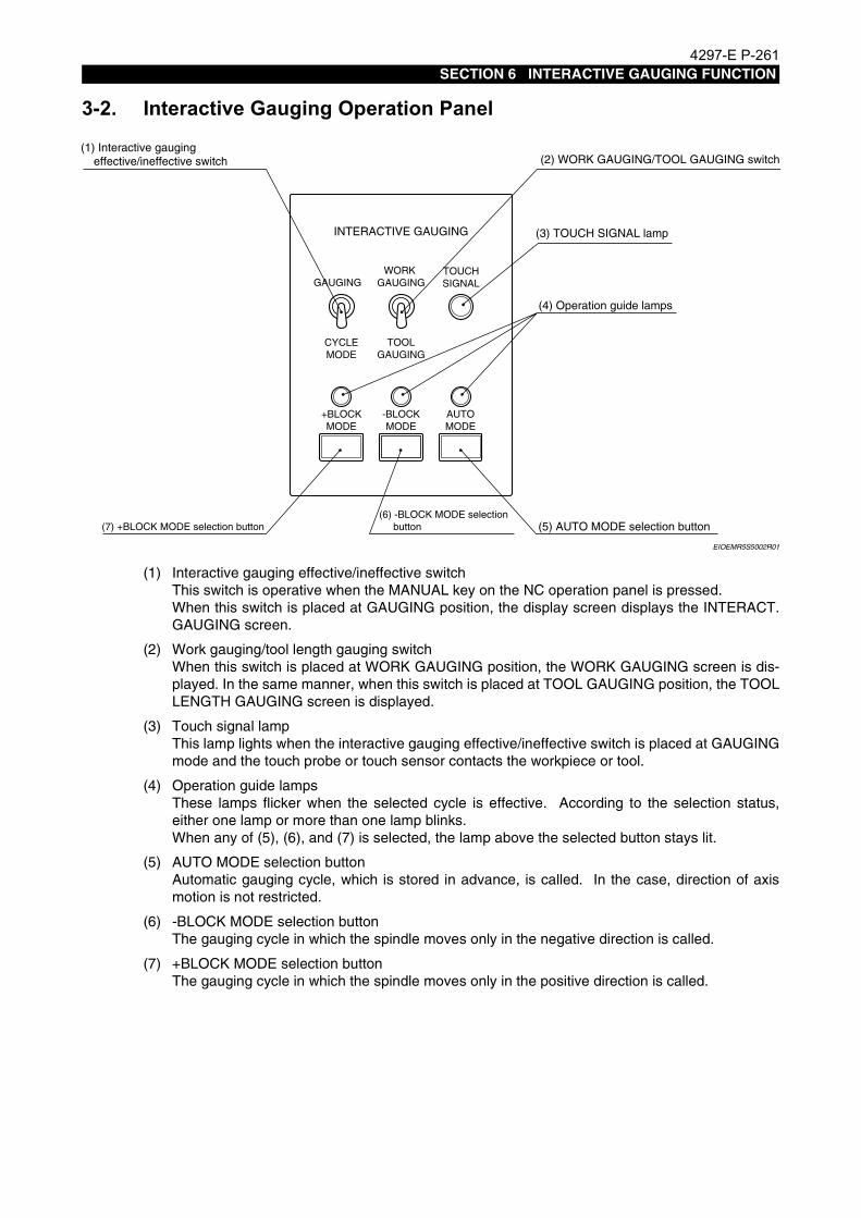
4297-E P-261SECTION 6 INTERACTIVE GAUGING FUNCTION
3-2. Interactive Gauging Operation PanelEeoemr5s5004
EIOEMR5S5002R01
(1) Interactive gauging effective/ineffective switchThis switch is operative when the MANUAL key on the NC operation panel is pressed. When this switch is placed at GAUGING position, the display screen displays the INTERACT.GAUGING screen.
(2) Work gauging/tool length gauging switchWhen this switch is placed at WORK GAUGING position, the WORK GAUGING screen is dis-played. In the same manner, when this switch is placed at TOOL GAUGING position, the TOOLLENGTH GAUGING screen is displayed.
(3) Touch signal lampThis lamp lights when the interactive gauging effective/ineffective switch is placed at GAUGINGmode and the touch probe or touch sensor contacts the workpiece or tool.
(4) Operation guide lampsThese lamps flicker when the selected cycle is effective. According to the selection status,either one lamp or more than one lamp blinks.When any of (5), (6), and (7) is selected, the lamp above the selected button stays lit.
(5) AUTO MODE selection buttonAutomatic gauging cycle, which is stored in advance, is called. In the case, direction of axismotion is not restricted.
(6) -BLOCK MODE selection buttonThe gauging cycle in which the spindle moves only in the negative direction is called.
(7) +BLOCK MODE selection buttonThe gauging cycle in which the spindle moves only in the positive direction is called.
INTERACTIVE GAUGING
WORK GAUGING
-BLOCKMODE
+BLOCKMODE
AUTOMODE
TOOLGAUGING
TOUCHSIGNAL
(4) Operation guide lamps
(5) AUTO MODE selection button(6) -BLOCK MODE selection button(7) +BLOCK MODE selection button
(3) TOUCH SIGNAL lamp
(2) WORK GAUGING/TOOL GAUGING switch(1) Interactive gauging effective/ineffective switch
GAUGING
CYCLEMODE

4297-E P-262SECTION 6 INTERACTIVE GAUGING FUNCTION
4. TerminologyEeoemr5s5005
EIOEMR5S5003R01
(1) SETSets the entered data as new data. To issue the SET command, press the function key [F1](SET), enter required data through the keyboard, and then press the WRITE key.Data cannot be set until the WRITE key is pressed.
(2) CALSets the data obtained by adding or subtracting the entered data to or from the preset value asnew data. To issue the CAL command, press the function key [F3] (CAL), enter required datathrough the keyboard, and then press the WRITE key.Data cannot be set until the WRITE key is pressed.
(3) BACKUPData such as tool length offset, origin of work coordinate system, and parameters (except sys-tem parameters) are stored in the memory at regular intervals as backup data. Therefore, if youturn off the power right after you change these data, they may remain unchanged. To changethe data securely, execute the BACKUP command by pressing the function key [F7] (BACKUP)before turning off the power.
(4) ZERO OFFSET NO. 10 (for system)This offset number is used to register the touch sensor position (setting of the REF surface) asthe preparatory step for the gauging operation. This offset number cannot be used in usualmachining program. It is not possible to change the number by moving the cursor on thescreen.
(5) TOOL LENGTH OFFSET NO. 5 (for system)This offset number is used as the tool offset number special to the touch probe as the prepara-tory step for the gauging operation. It is not possible to change the number by moving the cur-sor on the screen.
(6) REF RING CENTER HS3This is the coordinate system used to obtain the center of the REF ring for the touch probediameter compensation as the preparatory step for the gauging operation. It is not possible tochange the coordinate system number by moving the cursor on the screen.
F2
BS
SP
CAPSLOCK
! " DEL
PARAMETER
PMacMan
WRITE
RUN S.T.M SLIDEHOLD
PROGRAMSTOP LIMIT ALARM
AUTO MDI MANUAL EDIT AUX TOOL DATAZERO SET
A B C D E F G
H I J K L M N
O P Q R S T U
V W X Y Z : ,
# $ ( )
@ &,
? HT %
/^ [ ]|
- ;{ } < >
CTRL
UPPERCASE
CANPP */
+-=.0
1 2 34 5 67 8 9
F1 F3 F4 F5 F6 F7 F8
-
,

4297-E P-263SECTION 6 INTERACTIVE GAUGING FUNCTION
(7) Relative OffsetThe reference tool length is taken as "0" and tool offset is made based on the differencebetween the length of the tool in question and the reference tool length.
(8) Absolute OffsetLength of each tool is input directly and tool offset made based on the input length.The reference tool length is: 150 mm (5.91 in.) for NT No. 40 and 200 mm (7 .87 in.) for NT No.50.
(9) H.P. SET (ATC home position setting)This is effective only for vertical machining centers.The tool change position for tool length gauging cycle is set. After bringing the tool to the posi-tion where the ATC operation can be conducted safely, press the function key [F4] (H.P. SET).The position is registered as the ATC home position.The auto cycle for the tool length gauging is effective only after the home position has been set.Once set, the home position remains effective until the power is turned off.The set home position is lost when the power is turned off. Therefore, it is necessary to set thehome position after turning on the power.

4297-E P-264SECTION 6 INTERACTIVE GAUGING FUNCTION
5. Basic OperationEeoemr5s5006Because the manual gauging is carried out in the manual operation mode, all types of manual oper-
ations such as rapid feed, cutting feed and pulse handle feed are possible during the execution ofmanual gauging. Therefore, feed the touch probe or touch sensor manually until it is brought nearthe contact point.When bringing the touch sensor or touch probe into contact with the object, select the -SINGLE,+SINGLE, or AUTO by using the buttons on the specially prepared INTERACTIVE GAUGING oper-ation panel and press the CYCLE START button. The slide hold and override functions are effectivein this automatic touch detection cycle.In the slide hold mode, manual feed is also possible; to restart the automatic cycle operation, pressthe CYCLE START.The lamps above these cycle selection buttons flicker when the corresponding cycle is selectable.When the cycle is selected from those indicated by the flickering lamps, the lamp corresponding tothe selected cycle stays lit and other lamps go off. Pressing the CYCLE START button under suchcondition can begin the selected cycle.
Procedure :
1 Press the MANUAL key on the NC operation panel to select the manual operation mode.
2 Place the interactive gauging effective/ineffective switch at GAUGING position.This establishes the interactive gauging mode. Switching between WORK GAUGING modeand TOOL GAUGING mode is done using the work gauging/tool length gauging switch on theINTERACTIVE GAUGING operation panel.
EIOEMR5S5002R01
INTERACTIVE GAUGING
WORK GAUGING
-BLOCKMODE
+BLOCKMODE
AUTOMODE
TOOLGAUGING
TOUCHSIGNAL
(4) Operation guide lamps
(5) AUTO MODE selection button(6) -BLOCK MODE selection button(7) +BLOCK MODE selection button
(3) TOUCH SIGNAL lamp
(2) WORK GAUGING/TOOL GAUGING switch(1) Interactive gauging effective/ineffective switch
GAUGING
CYCLEMODE

4297-E P-265SECTION 6 INTERACTIVE GAUGING FUNCTION
6. Outline of Interactive Gauging FunctionEeoemr5s5007The interactive gauging function includes the following specification. For general specifications,
refer to Section 2, "LIST OF DISPLAY SCREEN".
(1) Work Gauging FunctionThis is the function to carry out the zero offset using the touch probe. This function provides thefollowing five gauging function to meet variety of workpiece shape:1. X, Y, Z END FACE2. I.D. CENTER3. O.D. CENTER4. INT END CENTER5. EXT END CENTER6. INCLINE, CORNER
EIOEMR5S5004R01
Before carrying out the work gauging function, always carry out the gauging PREPARATION(WORK) and PARAMETER (WORK).

4297-E P-266SECTION 6 INTERACTIVE GAUGING FUNCTION
(2) Tool Length Gauging FunctionThis is the function to carry out the tool length offset using the touch sensor.To carry out this function, a reference tool or a tool for which the length between the gauge lineand the tool nose is known is used as the "gauge".For the offset data, two types of offset data are available - relative offset data and absolute off-set data. The relative tool offset data uses the difference in lengths between the reference tooland a tool in question.The absolute tool offset data uses the length of the tool in question between the gauge line andthe tool nose.
EIOEMR5S5005R01
EIOEMR5S5006R01
Before carrying out the tool length gauging, always carry out the preparation for tool lengthgauging and set the gauging parameter data.
Gauge lineReference tool
Value "L" is registered as the tool length offset data
(Absolute Offset)
Value "L" is registered as the tool length offset data
(Relative Offset)
L
L

4297-E P-267SECTION 6 INTERACTIVE GAUGING FUNCTION
(3) Preparation for work gauging and setting the parametersBefore carrying out the work gauging cycle, it is necessary to set the data on the INTERACT.GAUGING PREPARATION (WORK) screen and the INTERACT. GAUGING PARAMETER(WORK) screen.
a) Preparatory step
EIOEMR5S5007R01
Before carrying out the work gauging function, it is necessary to set the tool offset data andtool radius compensation (4 directions of +X, -X, +Y, -Y) data of the touch probe itself.The touch probe length offset and radius compensation are required only when a touchprobe is changed or a touch probe has been struck against an obstacle.
b) Setting the gauging parameters
EIOEMR5S5008R01
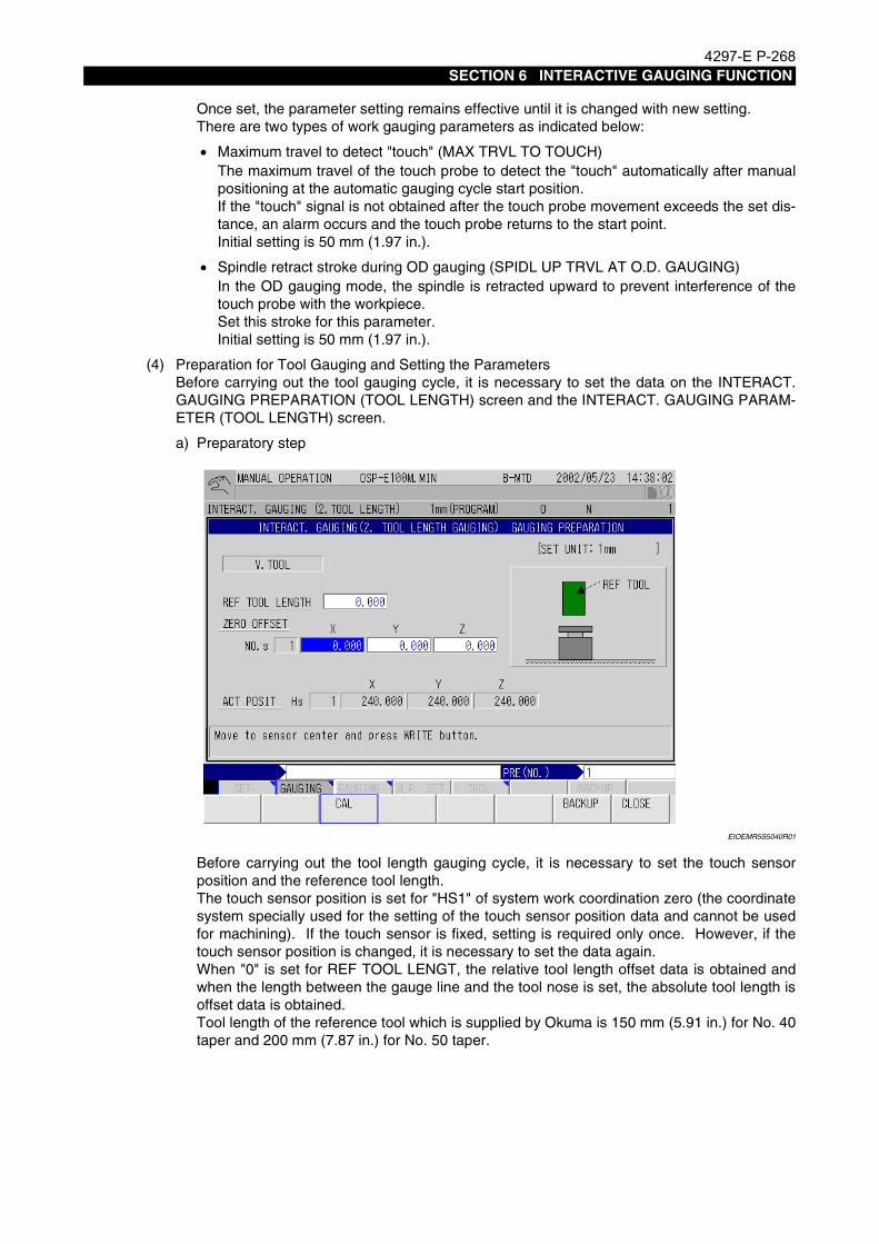
4297-E P-268SECTION 6 INTERACTIVE GAUGING FUNCTION
Once set, the parameter setting remains effective until it is changed with new setting.There are two types of work gauging parameters as indicated below:
• Maximum travel to detect "touch" (MAX TRVL TO TOUCH)The maximum travel of the touch probe to detect the "touch" automatically after manualpositioning at the automatic gauging cycle start position.If the "touch" signal is not obtained after the touch probe movement exceeds the set dis-tance, an alarm occurs and the touch probe returns to the start point.Initial setting is 50 mm (1.97 in.).
• Spindle retract stroke during OD gauging (SPIDL UP TRVL AT O.D. GAUGING)In the OD gauging mode, the spindle is retracted upward to prevent interference of thetouch probe with the workpiece.Set this stroke for this parameter.Initial setting is 50 mm (1.97 in.).
(4) Preparation for Tool Gauging and Setting the ParametersBefore carrying out the tool gauging cycle, it is necessary to set the data on the INTERACT.GAUGING PREPARATION (TOOL LENGTH) screen and the INTERACT. GAUGING PARAM-ETER (TOOL LENGTH) screen.
a) Preparatory step
EIOEMR5S5040R01
Before carrying out the tool length gauging cycle, it is necessary to set the touch sensorposition and the reference tool length.The touch sensor position is set for "HS1" of system work coordination zero (the coordinatesystem specially used for the setting of the touch sensor position data and cannot be usedfor machining). If the touch sensor is fixed, setting is required only once. However, if thetouch sensor position is changed, it is necessary to set the data again.When "0" is set for REF TOOL LENGT, the relative tool length offset data is obtained andwhen the length between the gauge line and the tool nose is set, the absolute tool length isoffset data is obtained.Tool length of the reference tool which is supplied by Okuma is 150 mm (5.91 in.) for No. 40taper and 200 mm (7.87 in.) for No. 50 taper.

4297-E P-269SECTION 6 INTERACTIVE GAUGING FUNCTION
b) Setting the gauging parameter
EIOEMR5S5010R01
Once set, the parameter setting remains effective until it is changed with new setting.There are two types of tool length gauging parameters as indicated below:
• Maximum travel to detect "touch" (MAX TRAVEL TO TOUCH)The maximum travel of the touch probe to detect the "touch" in the -BLOCK MODE aftermanual positioning at the gauging cycle start position.If the "touch" signal is not obtained after the touch probe movement exceeds the set dis-tance, an alarm occurs and the touch probe returns to the start point.Initial setting is 50 mm (1.97 in.).

4297-E P-270SECTION 6 INTERACTIVE GAUGING FUNCTION
• Maximum tool length (MAX TOOL LENGTH)Set the length of the longest tool that will be used in user's plant. The data to be set dif-fers depending on whether the relative tool length offset data is to be used or the abso-lute tool length offset data is to be used.The setting for this parameter determines the distance in which the tool advances to thetouch sensor at a rapid feedrate when the tool length offset data is read in the AUTOmode after setting HP. Because the tool will be hit against the touch sensor if the settingis too small, set the data taking safety into consideration.
EIOEMR5S5011R01
CAUTIONIf the maximum tool length is set to a value smaller than the actual tool length, the tool andthe touch sensor will collide.Never set the maximum tool length shorter than the actual tool length.
Touch sensor
HP position
1
Auto Mode Cycle
Rapid feed
Cutting feed
Operation sequence
2
3 4
5
Max. tool length +10 mm

4297-E P-271SECTION 6 INTERACTIVE GAUGING FUNCTION
7. Work Gauging Function
7-1. PARAMETER (WORK) ScreenEeoemr5s5008Procedure :
1 After selecting the MANUAL mode, place the interactive gauging switch at GAUGING position,and then place the work gauging/tool length gauging switch at WORK GAUGING position. Thescreen indicated below is displayed.
EIOEMR5S5004R01
2 Press the function key [F8] (GAUGING PARAM). The screen below will be displayed.
EIOEMR5S5008R01

4297-E P-272SECTION 6 INTERACTIVE GAUGING FUNCTION
3 Locate the cursor at the data column of MAX TRVL TO TOUCH L=. After inputting the value,press the function key [F1] (SET).
4 Locate the cursor at the data SPIDL UP TRVL AT O.D. GAUGING. After entering the value,press the function key [F1] (SET).
5 Press the function keys [F7] (BACKUP) and [F8] (CLOSE) in this order.
7-2. PREPARATION (WORK) ScreenEeoemr5s5009Prepare the followings:
- touch probe- reference ring- swing gauge- reference block- reference tool
Procedure :
1 After selecting the MANUAL mode, place the interactive gauging switch on the interactivegauging operation panel at GAUGING position, and then place the work gauging/tool lengthgauging switch at WORK GAUGING position.The screen as indicated below is displayed.
EIOEMR5S5004R01

4297-E P-273SECTION 6 INTERACTIVE GAUGING FUNCTION
2 Press the function key [F7] (GAUGING PREPARE). Screen below will be displayed.
EIOEMR5S5009R01
3 Locate the cursor at the data column of NXT TOOL and key in the reference tool registrationNo.Press the 1 CYCLE START key after moving the axes to the positions where the ATC opera-tion is possible.The reference tool is extracted from the ATC magazine and mounted to the spindle.
4 After the reference tool has been mounted to the spindle, manually bring the reference tool intocontact with the reference block.Then, move the cursor to the data column of ZERO OFFSET Z.
5 When the cursor is moved to the data column of ZERO OFFSET Z, the message "Write theREF block thickness" will be displayed on the screen. Key in the thickness (L) of referenceblock.

4297-E P-274SECTION 6 INTERACTIVE GAUGING FUNCTION
6 Press the function key [F5] (NEXT). Screen below will be displayed.
EIOEMR5S5012R01
7 Locate the cursor at the data column of NXT TOOL and key-in the touch probe registration No.Press the 1 CYCLE START key after moving the axes to the position where the ATC operationis possible.
8 After the touch probe has been mounted to the spindle, locate the cursor at the data column ofTOOL LENGTH OFFSET.
9 After confirming that the message "Position near REF face and select cycle" is displayed onthe screen, manually move the touch probe close to the reference surface.Press "Z" key to select Z-axis for gauging axis direction.Press -BLOCK MODE key on the INTERACTIVE GAUGING operation panel and then pressthe CYCLE START button.The touch probe will start the automatic gauging cycle.
10 The tool offset values are entered when the touch prove contacts the reference surface.

4297-E P-275SECTION 6 INTERACTIVE GAUGING FUNCTION
11 Press the function key [F5] (NEXT). This will display screen below.
EIOEMR5S5013R01
12 Fix the reference ring on the table.
13 Locate the cursor at the data column of REF RING DIA D and key-in the ring diameter.
14 After the completion of operation in step (13), the message "Find the ref ring center and pressWRITE button at that pos" is displayed on the screen. The cursor will advance to the data col-umn of REF RING CENTER.
15 Manually remove the touch probe from the spindle and press the swing gauge against the spin-dle.Leave marking on the touch probe to confirm the correct phase alignment with the drive keybefore removing the touch probe from the spindle.
16 Obtain the center of the reference ring by manually moving the swing gauge and align the cen-ter of reference ring and spindle center.
EIOEMR5S5014R01
Swing gauge
Datum ring
Table

4297-E P-276SECTION 6 INTERACTIVE GAUGING FUNCTION
Press the WRITE key at that position. The values for ZERO OFFSET NO. 3 (for system) (X, Y)will be changed and the cursor will advance to the data column of RAD COMP.
EIOEMR5S5015R01
17 While maintaining the X and Y axes at the center of the reference ring, retract the Z-axis.Remove the swing gauge from the spindle and mount the touch probe to the spindle whilealigning the match mark with the drive key.Then, manually carry out spindle orientation. If the touch probe radius compensation is carriedout without carrying out spindle orientation, a gauging error might be caused.
18 Lower Z-axis until the touch probe tip will come into the reference ring. Press "X" key to selectX-axis, and press AUTO MODE button and CYCLE START button in this order.

4297-E P-277SECTION 6 INTERACTIVE GAUGING FUNCTION
19 The touch probe will execute the automatic gauging cycle and the values for RAD COMP 1, 2,3 and 4 will be entered.
EIOEMR5S5007R01
EIOEMR5S5016R01
20 Pressing the function keys [F7] (BACKUP) and [F8] (CLOSE) in this order will return the screento the WORK GAUGING MENU screen.
Solid line : Cutting feedBroken line: Rapid feed
Automatic Gauging Cycle of Touch Probe
3
1
5
3
44
2
2
6
6
1
5
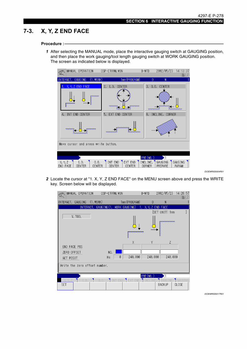
4297-E P-278SECTION 6 INTERACTIVE GAUGING FUNCTION
7-3. X, Y, Z END FACEEeoemr5s5010Procedure :
1 After selecting the MANUAL mode, place the interactive gauging switch at GAUGING position,and then place the work gauging/tool length gauging switch at WORK GAUGING position.The screen as indicated below is displayed.
EIOEMR5S5004R01
2 Locate the cursor at "1. X, Y, Z END FACE" on the MENU screen above and press the WRITEkey. Screen below will be displayed.
EIOEMR5S5017R01

4297-E P-279SECTION 6 INTERACTIVE GAUGING FUNCTION
3 Enter the ZERO OFFSET NO. (work coordinate No.).The work coordinate No. can be selected irrespective of the work coordinate No. currentlyeffective.
4 After the completion of operation in step 3, the zero offset values of the selected coordinatesystem and the actual position values in the selected coordinate system will be displayed.
EIOEMR5S5018R01
5 Move the touch probe close to the gauging position.
6 Select an axis along which the gauging cycle is carried out by pressing any of the AXISSELECT keys.When the axis is selected, the cursor will advance to the data column of the selected axis ofZERO OFFSET.
7 The indicating lamps of +BLOCK MODE and -BLOCK MODE flicker.

4297-E P-280SECTION 6 INTERACTIVE GAUGING FUNCTION
Select the direction in which the touch probe is moved. The indicating lamp of the directionselected will continue flickering, while the lamp of the direction not selected will stop flickering.
EIOEMR5S5002R01
8 Pressing the CYCLE START button starts the automatic gauging cycle in the selected direc-tion.
9 The touch probe moves at the speed determined by the cutting override switch setting until itwill contact the workpiece.
10 After the touch probe has contacted the workpiece, it will once retract for 0.5 mm from theworkpiece and then contact the workpiece again. The speed at which this motion is conductedis constant disregarding the cutting override switch setting.
11 After the second contact, the touch probe returns to the previous gauging position.
12 The zero offset data is changed; zero offset is carried out automatically so that the coordinatevalue of the contact position will be "0".
13 To set the zero offset data so that the contact position coordinate values will be other than "0",select an axis using the AXIS SELECT key and the cursor moves to the data area of theselected axis. Press the function key [F3] (CAL) and enter the required value.
INTERACTIVE GAUGING
WORK GAUGING
-BLOCKMODE
+BLOCKMODE
AUTOMODE
TOOLGAUGING
TOUCHSIGNAL
(4) Operation guide lamps
(5) AUTO MODE selection button(6) -BLOCK MODE selection button(7) +BLOCK MODE selection button
(3) TOUCH SIGNAL lamp
(2) WORK GAUGING/TOOL GAUGING switch(1) Interactive gauging effective/ineffective switch
GAUGING
CYCLEMODE

4297-E P-281SECTION 6 INTERACTIVE GAUGING FUNCTION
[Supplement]1) When a wrong operation mode has been selected +BLOCK MODE, -BLOCK MODE or wrong
zero offset data has been entered, press either the function key [F7] (QUIT) or RESET key.2) An alarm, indicating the gauging cycle is not possible, is lit in the following cases:
- The contact is not detected within the distance set for a parameter.- The CYCLE START switch is pressed after selecting the +BLOCK MODE or -BLOCK MODEwith the pulse handle selected.Press the RESET key to cancel the alarm state.
3) The direction in which an axis moves in the automatic cycle coincides with the direction of theaxis selected using the AXIS SELECT key.If a wrong axis is selected, the touch sensor will not move in the required direction.For ID or OD gauging, select the X-axis for automatic mode.The cursor on the screen moves to the axis which is selected using the AXIS SELECT key.That is, when X-axis is selected, the cursor moves to the X-axis data column of ZERO OFF-SET.
EIOEMR5S5020R01
EIOEMR5S5018R01
When the PULSE HANDLE is selected using the AXIS SELECT key, the cursor on the screen iscleared; if the gauging cycle is started under such condition, an alarm occurs.
X
4 5 PULSEHANDLE
Y Z
AXIS SELECT

4297-E P-282SECTION 6 INTERACTIVE GAUGING FUNCTION
7-4. I.D. CENTEREeoemr5s5011Procedure :
1 After selecting the manual mode, place the interactive gauging switch at GAUGING position,and then place the work gauging/tool length gauging switch at WORK GAUGING position.The screen as indicated below is displayed.
EIOEMR5S5004R01
2 Locate the cursor at the data column of "2. I.D. CENTER" on the above screen and press theWRITE key.Screen below will be displayed.
EIOEMR5S5021R01
3 Enter the ZERO OFFSET NO. (work coordinate No.).

4297-E P-283SECTION 6 INTERACTIVE GAUGING FUNCTION
4 The indicating lamps of +BLOCK MODE and AUTO MODE flicker.
5 The message "Position near end-face, select axis, then select cycle" will be displayed on thescreen.Feed the touch probe manually to the following position and then feed it into the hole.
[Supplement]
6 AUTO MODEWhen the AUTO MODE is selected, the indicating lamp of AUTO MODE will continue flicker-ing.Select the X-axis using the AXIS SELECT key and press the CYCLE START button.The gauging cycle starts and gauging is carried out in the sequence of X-axis, Y-axis, and X-axis. Finally, the touch probe stops at the center of the hole and the gauging cycle is com-pleted. The zero offset of X- and Y-axes is carried out so that the X and Y coordinate values ofthe center of the hole will be (0, 0).
7 +BLOCK MODEWhen the +BLOCK MODE is selected, the indicating lamp of +BLOCK MODE will continueflickering.
EIOEMR5S5022R01
(1) Feed the touch probe manually close to point "1" as illustrated below and insert it into thehole.
EIOEMR5S5023R01
AUTO MODE .... Near the center of the hole
+BLOCK MODE .... Near the wall of the hole in the +X-axis direction
Selection of the AUTO MODE and +BLOCK MODE should be made according to the IDdimension. AUTO MODE ......... The ID is 2 x max. travel or less to touch. +BLOCK MODE ...... The ID is greater than 2 x max. travel to touch.The initial setting for this parameter is 50 mm (1.97 in.).Change the setting as needed.
-BLOCK MODE
+BLOCK MODE AUTO
Manual feed
12
X
Y

4297-E P-284SECTION 6 INTERACTIVE GAUGING FUNCTION
(2) Select the X-axis using the AXIS SELECT key and press the CYCLE START button.
(3) The gauging cycle starts; the touch probe moves in the positive direction of X-axis andafter the detection of "contact", it returns to the previously located position.
(4) The indicating lamp of AUTO MODE continues flickering, while the indicating lamp of+BLOCK MODE stops flickering.
(5) Manually feed the touch probe close to point "2" as shown in (1).In this axis movement, move only X-axis and do not move Y-axis. If Y-axis is moved, theresults of the gauging cycle are not correct.
(6) Select the X-axis using the AXIS SELECT key and press the cycle start switch.
EIOEMR5S5024R01
(7) The gauging cycle starts; the touch probe moves in the negative direction of X-axis andafter the detection of "contact", it moves to the center position. Then, the cycle is contin-uously carried out in the order of Y-axis and X-axis. Finally, the touch probe stops at thecenter of the hole.After the completion of gauging, the zero offset of X- and Y-axes is carried out so thatthe X and Y coordinate values of the center of the hole will be (0, 0). At the same time,the ID measurement is also displayed.
(8) When zero offset is required so that the coordinate values of the obtained center of thehole will be other than "0", select the axis using the AXIS SELECT key. The cursormoves to the data area of the corresponding axis on the screen. Press the function key[F3] (CAL) and enter the required value.
-BLOCK MODE
+BLOCK MODE
AUTO

4297-E P-285SECTION 6 INTERACTIVE GAUGING FUNCTION
7-5. O.D. CENTEREeoemr5s5012Procedure :
1 After selecting the manual mode, place the interactive gauging switch at GAUGING position,and then place the work gauging/tool length gauging switch at WORK GAUGING position.Screen as indicated below will be displayed.
EIOEMR5S5004R01
2 Locate the cursor at the data column of "3. O.D. CENTER" on the above screen ad press theWRITE key.Screen below will be displayed.
EIOEMR5S5025R01
3 Enter the ZERO OFFSET NO. (work coordinate No.).

4297-E P-286SECTION 6 INTERACTIVE GAUGING FUNCTION
4 The indicating lamp of -BLOCK MODE will flicker.
5 Manually move the touch probe to the position "1" of the drawing below.
EIOEMR5S5026R01
After the positioning of the X- and Y-axes, move the touch probe down; the infeed amount ("A"in drawing above) must be smaller than the spindle retract stroke set for SPIDL UP TRVL ATO.D. GAUGING.
6 Select the X-axis using the AXIS SELECT key, select the -BLOCK MODE and press theCYCLE START button.
7 The gauging cycle starts; the touch probe moves in the negative direction of X-axis and afterthe detection of "contact", it returns to the previously located position and then the Z-axismoves upward.The Z-axis upward movement amount is as the amount set for SPIDLE UP TRVL AT O.D.GAUGING. The initial setting for this parameter is 50 mm. Change the setting when needed.
8 Manually move the touch probe close to position "2" in drawing in 5. In this axis movement,move only X-axis and do not move Y-axis. If Y-axis is moved, the results obtained in the gaug-ing cycle will not be correct.
9 Select the X-axis using the AXIS SELECT key, select the AUTO MODE and press the CYCLESTART button.
10 The gauging cycle starts; the touch probe moves in the positive direction of X-axis and after thedetection of "contact", the Z-axis moves upward and then to the center of the OD.The gauging is carried out in the sequence of Y-axis and X-axis while Z-axis moves upwardand downward. Finally the touch probe stops at the center of the hole.The zero offset of X- and Y-axes is carried out so that the X and Y coordinate values of thecenter of the hole will be (0, 0).At the same time, the OD measurement is also displayed.
11 When zero offset is required so that the coordinate values of the obtained center of the hole willbe other than "0", select the axis using the AXIS SELECT key. The cursor moves to the dataarea of the corresponding axis on the screen. Press the function key [F3] (CAL) and enter therequired value.
Manual feed
12
X
A
Y

4297-E P-287SECTION 6 INTERACTIVE GAUGING FUNCTION
7-6. INT END CENTEREeoemr5s5013Procedure :
1 After selecting the manual mode, place the interactive gauging switch at GAUGING position,and then place the work gauging/tool length gauging switch at WORK GAUGING position.The screen as indicated below is displayed.
EIOEMR5S5004R01
2 Locate the cursor at "4. INT END CENTER" on the above screen and press the WRITE key.Screen below will be displayed.
EIOEMR5S5027R01

4297-E P-288SECTION 6 INTERACTIVE GAUGING FUNCTION
3 Enter the ZERO OFFSET NO. (work coordinate No.).
4 The indicating lamps of +BLOCK MODE and AUTO MODE will flicker.
5 The message "Position near end-face, select axis, then select cycle" will be displayed on thescreen.Feed the touch probe manually to the following position and then feed it into the groove.
[Supplement]
6 AUTO MODEWhen AUTO MODE is selected, the indicating lamp of AUTO MODE will continue flickering.Select an axis along which the gauging cycle is carried out using the AXIS SELECT key andpress the CYCLE START button.The gauging cycle starts. The zero offset is carried out so that the coordinate value of the cen-ter of the internal end face will be "0".
EIOEMR5S5028R01
AUTO MODE .... Near the center of the internal end face
+BLOCK MODE .... Near the wall of the groove in the positive direction of the selected axis
Selection of the AUTO MODE and +BLOCK MODE should be made according to the internalend face dimension. AUTO MODE ........ When the internal end face is 2 x max. travel or less to touch. +BLOCK MODE ..... When the internal end face is greater than 2 x max. travel to touch.The initial setting for this parameter is 50 mm (1.97 in.). Change the setting as needed.
Y-axis zero offset
X-axis zero offset
1
12
2X
Y
Manual feed

4297-E P-289SECTION 6 INTERACTIVE GAUGING FUNCTION
7 +BLOCK MODEWhen the +BLOCK MODE is selected, the indicating lamp of +BLOCK MODE will continueflickering.When the +BLOCK MODE is selected, the indicating lamp of +BLOCK MODE willcontinue flickering.
(1) Move the touch probe manually close to point "1" as illustrated below and insert it intothe groove.
EIOEMR5S5029R01
(2) Select an axis using the AXIS SELECT key and press the CYCLE START button.
(3) The gauging cycle starts. After the completion of gauging, the touch probe returns to thepreviously located position.
(4) Move the touch probe close to the opposite wall of the groove.
(5) Select an axis using the AXIS SELECT key, select the -BLOCK MODE and press theCYCLE START button.After the completion of gauging, the zero offset of the axis gauged is carried out so thatthe coordinate value of the center will be "0". At the same time, the internal end facedimension (width between walls) is also displayed.
(6) When zero offset is required so that the coordinate value of the obtained center will beother than "0", select the axis using the AXIS SELECT key. The cursor moves to thedata area of the corresponding axis on the screen. Press the function key [F3] (CAL)and enter the required value.
[Supplement]In this example, the -BLOCK MODE cycle is carried out after the completion of the +BLOCKMODE cycle. The operation in the reverse order is also possible.
12

4297-E P-290SECTION 6 INTERACTIVE GAUGING FUNCTION
7-7. EXT END CENTEREeoemr5s5014Procedure :
1 After selecting the manual mode, place the interactive gauging switch at GAUGING positionand then place the work gauging/tool length gauging switch at WORK GAUGING position.The screen as indicated below is displayed.
EIOEMR5S5004R01
2 Locate the cursor at "5. EXT END CENTER" on the above screen and press the WRITE key.Screen below will be displayed.
EIOEMR5S5030R01

4297-E P-291SECTION 6 INTERACTIVE GAUGING FUNCTION
3 Enter the ZERO OFFSET NO. (work coordinate No.).
4 The indicating lamp of -BLOCk MODE will flicker.
5 Manually move the touch probe to the position "1" of the drawing below.After the positioning of the X- and Y-axes, move the touch probe down; this infeed amount ("A"in drawing above) must be smaller than the spindle retract stroke set for SPIDL UP TRVL ATO.D. GAUGING.
EIOEMR5S5031R01
6 Select an axis along which the gauging cycle is carried out by pressing any of the AXISSELECT keys.Press the -BLOCK MODE button and the CYCLE START button.
7 The gauging cycle starts. After the completion of gauging, the touch probe returns to the previ-ously located position.
8 Manually move the touch probe close to the opposite side wall.
9 Select an axis using the AXIS SELECT key, select the +BLOCK MODE and press the CYCLESTART button.After the completion of gauging, the zero offset of the axis gauged is carried out so that thecoordinate value of the center will be "0". At the same time, the external end face dimension isalso displayed.
10 When zero offset is required so that the coordinate value of the obtained center will be otherthan "0", select the axis using the AXIS SELECT key. The cursor moves to the data area of thecorresponding axis on the screen. Press the function key [F3] (CAL) and enter the requiredvalue.
Y-axis zero offset
X-axis zero offset
1
2
12
X
A
Y

4297-E P-292SECTION 6 INTERACTIVE GAUGING FUNCTION
[Supplement]In this example, the -BLOCK MODE cycle is carries out after the completion of the +BLOCK MODEcycle. The operation in the reverse order is also possible.Select "5. EXT END CENTER" for the case indicated below where the touch probe is brought intocontact twice in the same direction.
EIOEMR5S5032R01

4297-E P-293SECTION 6 INTERACTIVE GAUGING FUNCTION
7-8. INCLINE, CORNEREeoemr5s5015Procedure :
1 Select the "MAN. OPERATION" mode. Set the interactive gauging effective/ineffective switchon the interactive gauging operation panel to "GAUGING". Set the WORK GAUGING/TOOL GAUGING switch to "WORK GAUGING". The followingscreen appears.
EIOEMR5S5004R01
2 Locate the cursor at "6. INCLINE, CORNER" on the above MENU screen and press theWRITE key to display the screen below.
EIOEMR5S5033R01
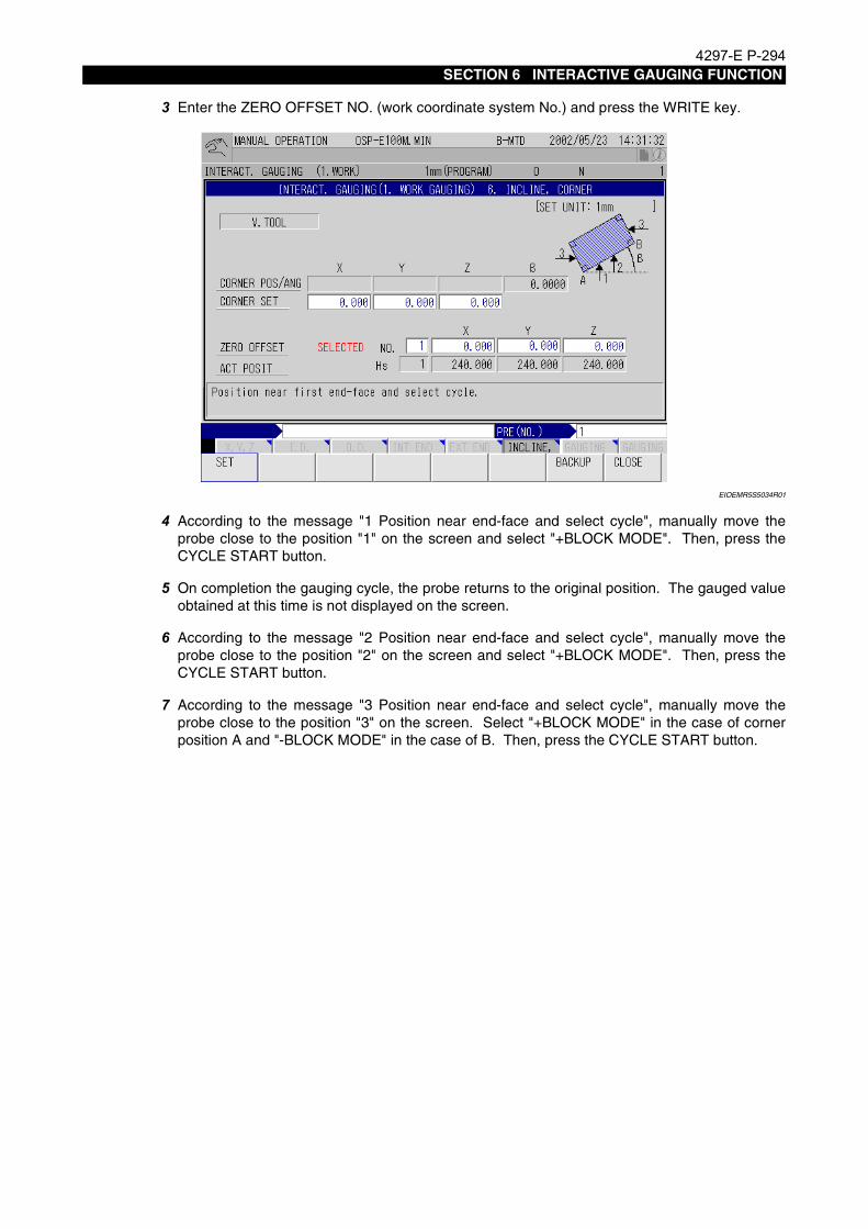
4297-E P-294SECTION 6 INTERACTIVE GAUGING FUNCTION
3 Enter the ZERO OFFSET NO. (work coordinate system No.) and press the WRITE key.
EIOEMR5S5034R01
4 According to the message "1 Position near end-face and select cycle", manually move theprobe close to the position "1" on the screen and select "+BLOCK MODE". Then, press theCYCLE START button.
5 On completion the gauging cycle, the probe returns to the original position. The gauged valueobtained at this time is not displayed on the screen.
6 According to the message "2 Position near end-face and select cycle", manually move theprobe close to the position "2" on the screen and select "+BLOCK MODE". Then, press theCYCLE START button.
7 According to the message "3 Position near end-face and select cycle", manually move theprobe close to the position "3" on the screen. Select "+BLOCK MODE" in the case of cornerposition A and "-BLOCK MODE" in the case of B. Then, press the CYCLE START button.
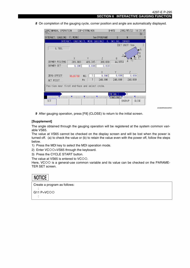
4297-E P-295SECTION 6 INTERACTIVE GAUGING FUNCTION
8 On completion of the gauging cycle, corner position and angle are automatically displayed.
EIOEMR5S5035R01
9 After gauging operation, press [F8] (CLOSE) to return to the initial screen.
[Supplement]
NOTICE
The angle obtained through the gauging operation will be registered at the system common vari-able VS65.The value at VS65 cannot be checked on the display screen and will be lost when the power isturned off. (a) to check the value or (b) to retain the value even with the power off, follow the stepsbelow.1) Press the MDI key to select the MDI operation mode.2) Enter VC =VS65 through the keyboard.3) Press the CYCLE START button.The value at VS65 is entered to VC .Here, VC is a general-use common variable and its value can be checked on the PARAME-TER SET screen.
Create a program as follows: :G11 P=VC :

4297-E P-296SECTION 6 INTERACTIVE GAUGING FUNCTION
8. Tool Length Gauging
8-1. Parameter (Tool Length)Eeoemr5s5016Procedure :
1 After selecting the manual mode, place the interactive gauging switch at GAUGING position,and then place the work gauging/tool length gauging switch at TOOL GAUGING position.The screen as indicated below is displayed.
EIOEMR5S5005R01
2 Press the function key [F3] (GAUGING PARAM).Screen below will be displayed.
EIOEMR5S5010R01
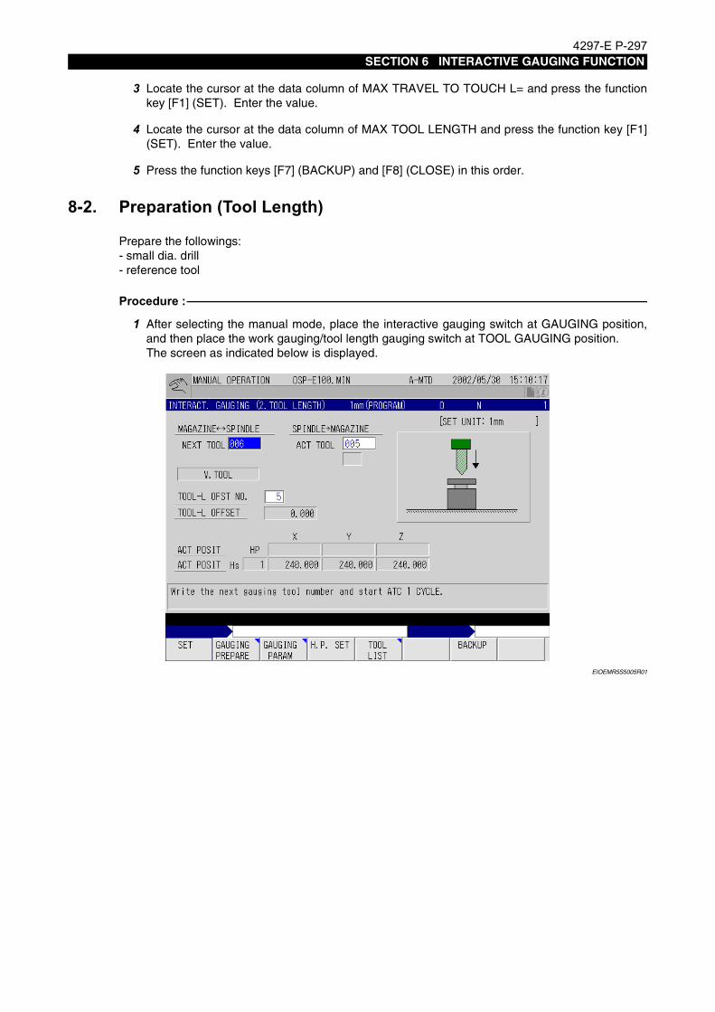
4297-E P-297SECTION 6 INTERACTIVE GAUGING FUNCTION
3 Locate the cursor at the data column of MAX TRAVEL TO TOUCH L= and press the functionkey [F1] (SET). Enter the value.
4 Locate the cursor at the data column of MAX TOOL LENGTH and press the function key [F1](SET). Enter the value.
5 Press the function keys [F7] (BACKUP) and [F8] (CLOSE) in this order.
8-2. Preparation (Tool Length)Eeoemr5s5017Prepare the followings:
- small dia. drill- reference tool
Procedure :
1 After selecting the manual mode, place the interactive gauging switch at GAUGING position,and then place the work gauging/tool length gauging switch at TOOL GAUGING position.The screen as indicated below is displayed.
EIOEMR5S5005R01

4297-E P-298SECTION 6 INTERACTIVE GAUGING FUNCTION
2 After confirming that the message "Write the next gauging tool number and start ATC 1CYCLE" is displayed on the above screen, press the function key [F1] (SET) and key-in theregistration No. of the small dia. drill. (This operation is necessary to align the center of the drilltool (X-, Y-axes) and the center of the touch sensor.)
EIOEMR5S5041R01
3 Press the 1 CYCLE START key and mount the small dia. drill to the spindle.
4 Align the center of the drill (X-, Y-axes) and the center of the touch sensor. (by eye measureallowed)
5 Press the function key [F2] (GAUGING PREPARE).
6 Locate the cursor at the data column of ZERO OFFSET X and press the WRITE key.The zero offset for X-axis will be executed.
7 Locate the cursor at the data column of ZERO OFFSET Y and press the WRITE key.The zero offset for Y-axis will be executed.
8 Move Z-axis upward while holding X- and Y-axis at that position, and remove the small dia. drillin the spindle and mount the reference tool instead.

4297-E P-299SECTION 6 INTERACTIVE GAUGING FUNCTION
9 Manually move the Z-axis downward and locate the reference tool close to the touch sensor.The distance between the reference tool and the touch sensor must be smaller than the valueset for MAX TRAVEL TO TOUCH L.The initial setting for this parameter is 50 mm (1.97 in.).
EIOEMR5S5036R01
10 After pressing the -BLOCK MODE key, select Z-axis by pressing the AXIS SELECT key.Then, press the CYCLE START button.
11 The gauging cycle starts. After the reference tool has contacted the touch probe, the referencetool returns to the previously located position.
12 Press the function keys [F7] (BACKUP) and [F8] (CLOSE) in this order.
13 Move the Z-axis upward. Manually remove the reference tool from the spindle and mount thesmall dia. drill instead.
14 Move the spindle to the position where ATC operation is possible (Z-axis ... plus limit, Y- and Z-axis ... position which is free of interference) and press the function key [F4] (H.P. SET). Thisposition is set as the home position for tool change operation.
15 Press the 1 CYCLE START key without setting the data for next tool. The small dia. drill will bereturned to the ATC magazine.
16 To proceed with the tool length gauging cycle, key-in the registration No. of the tool at NXTTOOL and carry out the 1 CYCLE START function.
L

4297-E P-300SECTION 6 INTERACTIVE GAUGING FUNCTION
8-3. Tool Length GaugingEeoemr5s5018The tool length gauging cycle consists of the two modes - -BLOCK MODE and AUTO MODE.
For both the -BLOCK MODE and AUTO MODE, select Z-axis using the AXIS SELECT key.Use these modes to measure the tool length of a boring bar, face milling cutter, end mill and othertypes of cutting tools which do not have the cutting tip at the center of the tool because manual oper-ation (spindle free, manual pulse feed, rapid feed) is allowed during slide hold mode.To restart the operation after activating the slide hold function, press the CYCLE START button.
Procedure :
1 After selecting the manual mode, place the interactive gauging switch at the GAUGING posi-tion, and then place the work gauging/tool length gauging switch at the TOOL GAUGING posi-tion.The screen as indicated below is displayed.
EIOEMR5S5005R01
2 The cursor is located at the data column of NXT TOOL. After keying-in the registration No. ofthe tool to be gauged, press the 1 CYCLE START key.
-BLOCk MODE .... The gauging cycle is carried out after a cutting tool is positioned above the touch sensor manually. In this mode, only Z-axis is controlled and after the detection of "contact", the cutting tool returns to the previously located position.
AUTO MODE .... The cycle is enabled after the HP (ATC position for interactive gauging operation) has been set. The cutting tool is positioned automatically at a position above the touch sensor and then the Z-axis moves down until the "contact" is detected.After the detection of "contact", the cutting tool returns to the HP posi-tion.

4297-E P-301SECTION 6 INTERACTIVE GAUGING FUNCTION
3 The cursor moves to the data column of TOOL-L OFST NO. Enter the tool length offset num-ber.
EIOEMR5S5037R01
4 When the tool offset number is entered, the -BLOCK MODE and AUTO MODE indicatinglamps will light up.
5 The cursor moves to the data column of TOOL-L OFFSET.
6 -BLOCK MODE
EIOEMR5S5038R01
(a) Manually move the cutting tool above the touch sensor and select Z-axis with the AXISSELECT key.

4297-E P-302SECTION 6 INTERACTIVE GAUGING FUNCTION
(b) Press the -BLOCK MODE switch and then the CYCLE START button.
(c) When the cutting tool is brought into contact with the touch sensor, the tool length offsetvalue is displayed automatically and the Z-axis moves up.
7 AUTO MODE
(a) Press the AUTO MODE switch and the CYCLE START button. The cutting tool beginsmoving from the HP (home position) automatically until it is brought into contact with thetouch sensor.
(b) Upon contact with the touch sensor, the tool length offset data is automatically dis-played.
(c) The cutting tool returns to the HP automatically.
[Supplement]Setting the HPAfter positioning the cutting tool at a position (X, Y, Z) where interference will not occur whenthe ATC cycle is carried out, press the function key [F4] (H.P. SET).Because the set HP is lost when the power is turned off, it in necessary to set the HP eachtime the power is turned on.

4297-E P-303SECTION 6 INTERACTIVE GAUGING FUNCTION
9. Other Supplementary ExplanationsEeoemr5s5019When the work gauging cycle is carried out, zero point is automatically offset at the completion of
the cycle. However, if automatic zero offsetting is not required and only the work gauging should becarried out, set "0" for bit 7 of NC optional parameter (bit) No. 46. Initial setting is "1" when themachine is shipped.
EIOEMR5S5038R01
For carrying out the tool length gauging cycle, this manual assumes that all tools are stored in thetool magazine and that the tool for which the tool gauging cycle is to be carried out is set in the spin-dle in the automatic tool change cycle. In other word, the required tool is set in the spindle by carry-ing out the automatic tool change cycle after entering the corresponding tool number for NXT TOOL.If the tool to be gauged is set in the spindle by hand instead of using the ATC, and if that tool isreturned to the tool magazine using the ATC, enter the tool number of manually set tool for ACTTOOL. To return the tool to the required pot in the tool magazine, enter the pot number at POT NO.before starting the ATC cycle. If the tool may be returned to any pot, carry out the ATC cycle withoutdesignation the return pot number.In this case, the tool is returned to an empty pot automatically.
(1) NC parameters
a) Set whether or not the automatic zero setting is carried out when the work gauging cycle iscarried out.NC optional parameter (bit) No. 46, bit 7
b) Set whether only the automatic cycle is effective or both the automatic and block cycles areeffective at the start of the work gauging cycle.NC optional parameter (bit) No. 46, bit 6
1 : Automatic zero setting is carried out.
0 : Only gauging is carried out.
1 : Both the block and automatic modes are effective.
0 : Only the automatic mode is effective.
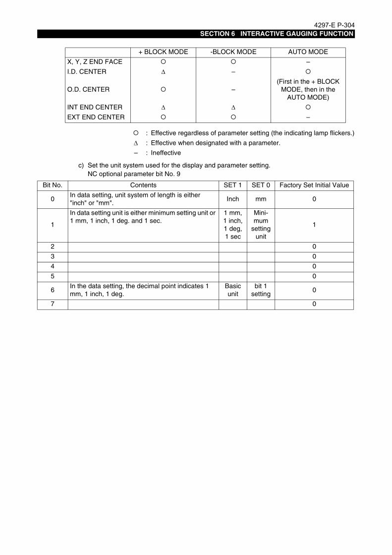
4297-E P-304SECTION 6 INTERACTIVE GAUGING FUNCTION
c) Set the unit system used for the display and parameter setting.NC optional parameter bit No. 9
+ BLOCK MODE -BLOCK MODE AUTO MODE
X, Y, Z END FACE –
I.D. CENTER ∆ –
O.D. CENTER –(First in the + BLOCK
MODE, then in the AUTO MODE)
INT END CENTER ∆ ∆EXT END CENTER –
: Effective regardless of parameter setting (the indicating lamp flickers.)
∆ : Effective when designated with a parameter.
– : Ineffective
Bit No. Contents SET 1 SET 0 Factory Set Initial Value
0In data setting, unit system of length is either "inch" or "mm".
Inch mm 0
1
In data setting unit is either minimum setting unit or 1 mm, 1 inch, 1 deg. and 1 sec.
1 mm, 1 inch,1 deg, 1 sec
Mini-mum
setting unit
1
2 0
3 0
4 0
5 0
6In the data setting, the decimal point indicates 1 mm, 1 inch, 1 deg.
Basic unit
bit 1 setting
0
7 0
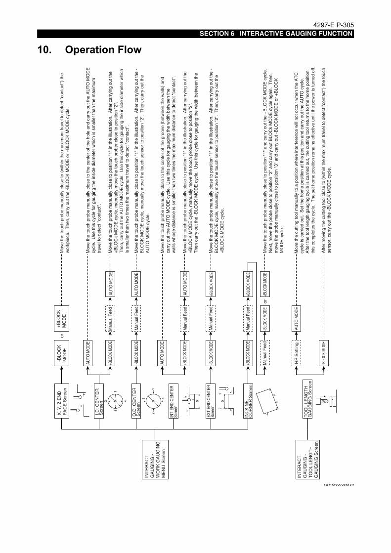
4297-E P-305SECTION 6 INTERACTIVE GAUGING FUNCTION
10. Operation FlowEeoemr5s5020
EIOEMR5S5039R01
INT
ER
AC
T.
GA
UG
ING
-
WO
RK
GA
UG
ING
M
EN
U S
cree
n
I.D. C
EN
TE
R
Scr
een
INT
END
CEN
TER
Sc
reen
INC
KIN
E,
CO
RN
ER
Scr
een
X, Y
, Z E
ND
F
AC
E S
cree
n-B
LOC
K
MO
DE
or
03 4
12
0
3 4
12
or
+BLO
CK M
ODE
AUTO
MO
DE
+BLO
CK
M
OD
E
Man
ual F
eed
INT
ER
AC
T.
GA
UG
ING
-
TO
OL
LEN
GT
H
GA
UG
ING
Scr
een
TO
OL
LEN
GT
H
GA
UG
ING
Scr
een
HP
Set
ting
AUTO
MO
DE
Mov
e th
e to
uch
prob
e m
anua
lly c
lose
to p
ositi
on "
1" in
the
illus
trat
ion.
Afte
r ca
rryi
ng o
ut th
e +B
LOC
k M
OD
E c
ycle
, man
ually
mov
e th
e to
uch
prob
er c
lose
to p
ositi
on "
2".
The
n, c
arry
out
the
AU
TO
MO
DE
cyc
le.
Use
this
cyc
le fo
r ga
ugin
g th
e in
side
dia
met
er w
hich
is
sm
alle
r th
an tw
o tim
es th
e m
axim
um tr
avel
to d
etec
t "co
ntac
t".
Mov
e th
e cu
tting
tool
man
ually
to a
pos
ition
whe
re in
terf
eren
ce w
ill n
ot o
ccur
whe
n th
e A
TC
cy
cle
is c
arrie
d ou
t. S
et th
e ho
me
posi
tion
at th
is p
ositi
on a
nd c
arry
out
the
AU
TO
cyc
le.
Afte
r th
e to
ol le
ngth
gau
ging
cyc
le is
car
ried
out,
the
cutti
ng to
ol r
etur
ns to
the
hom
e po
sitio
n;
this
com
plet
es th
e cy
cle.
The
set
hom
e po
sitio
n re
mai
ns e
ffect
ive
until
the
pow
er is
turn
ed o
ff.
Mov
e th
e to
uch
prob
e m
anua
lly c
lose
to p
ositi
on "
1" a
nd c
arry
out
the
+BLO
CK
MO
DE
cyc
le.
Nex
t, m
ove
the
prob
e cl
ose
to p
ositi
on "
2" a
nd c
arry
out
BLO
Ck
MO
DE
cyc
le a
gain
. T
hen,
m
ove
the
prob
e m
anua
lly c
lose
to p
ositi
on "
3" a
nd c
arry
out
-B
LOC
K M
OD
E o
r +B
LOC
K
MO
DE
cyc
le.
Afte
r m
ovin
g th
e cu
tting
tool
clo
se to
(w
ithin
the
max
imum
trav
el to
det
ect "
cont
act"
) th
e to
uch
sens
or, c
arry
out
the
-BLO
CK
MO
DE
cyc
le.
Mov
e th
e to
uch
prob
e m
anua
lly c
lose
to p
ositi
on "
1" in
the
illus
trat
ion.
Afte
r ca
rryi
ng o
ut th
e -
BLO
CK
MO
DE
cyc
le, m
anua
lly m
ove
the
touc
h se
nsor
to p
ositi
on "
2".
The
n, c
arry
out
the
AU
TO
MO
DE
cyc
le.
Mov
e th
e to
uch
prob
e m
anua
lly c
lose
to p
ositi
on "
1" in
the
illus
trat
ion.
Afte
r ca
rryi
ng o
ut th
e -
BLO
CK
MO
DE
cyc
le, m
anua
lly m
ove
the
touc
h se
nsor
to p
ositi
on "
2".
The
n, c
arry
out
the
+BLO
CK
MO
DE
cyc
le.
Mov
e th
e to
uch
prob
e m
anua
lly c
lose
to th
e ce
nter
of t
he g
roov
e (b
etw
een
the
wal
ls)
and
carr
y ou
t the
AU
TO
MO
DE
cyc
le.
Use
this
cyc
le fo
r ga
ugin
g th
e w
idth
bet
wee
n th
e w
alls
who
se d
ista
nce
is s
mal
ler
than
two
times
the
max
imum
dis
tanc
e to
det
ect "
cont
act"
.
Mov
e th
e to
uch
prob
e m
anua
lly c
lose
to p
ositi
on "
1" in
the
illus
trat
ion.
Afte
r ca
rryi
ng o
ut th
e +B
LOC
K M
OD
E c
ycle
, man
ually
mov
e th
e to
uch
prob
e cl
ose
to p
ositi
on "
2".
The
n ca
rry
out t
he -
BLO
CK
MO
DE
cyc
le.
Use
this
cyc
le fo
r ga
ugin
g th
e w
idth
bet
wee
n th
e
Mov
e th
e to
uch
prob
e m
anua
lly c
lose
to (
with
in th
e m
axim
um tr
avel
to d
etec
t "co
ntac
t")
the
wor
kpie
ce.
The
n, c
arry
out
the
-BLO
CK
MO
DE
or
+BLO
CK
MO
DE
cyc
le.
Mov
e th
e to
uch
prob
e m
anua
lly c
lose
to th
e ce
nter
of t
he h
ole
and
carr
y ou
t the
AU
TO
MO
DE
cy
cle.
Use
this
cyc
le fo
r ga
ugin
g th
e in
side
dia
met
er w
hich
is s
mal
ler
than
the
max
imum
tr
avel
to d
etec
t "co
ntac
t".
01
2
01
2
AUTO
MO
DE
O.D
. CE
NT
ER
S
cree
n-B
LOCK
MOD
EM
anua
l Fee
dAU
TO M
OD
E
AUTO
MO
DE
+BLO
CK M
ODE
Man
ual F
eed
AUTO
MO
DE
EXT
END
CEN
TER
Sc
reen
-BLO
CK M
ODE
Man
ual F
eed
+BLO
CK M
ODE
+BLO
CK M
ODE
Man
ual F
eed
+BLO
CK M
ODE
Man
ual F
eed
-BLO
CK M
ODE
+BLO
CK M
ODE
-BLO
CK M
ODE

4297-E P-306SECTION 6 INTERACTIVE GAUGING FUNCTION
11. Error ListEeoemr5s5021No. Error Message Contents
Cutter R. comp input NO. 2713
(1) The designated cutter radius compensation number is "0" or smaller, orgreater than the number of compensation pairs selected with user'sspecification.
a. Tool data 300-pair specificationThe input number is greater than 301.
b. Tool data 200-pair specificationThe input number is greater than 201.
c. Tool data 100-pair specificationThe input number is greater than 101.
(2) The cutter radius compensation number has not been designated whenthe cutter radius compensation data should be designated.
Zero set input NO. 2714
(1) The designated zero offset number is "0" or smaller, or greater than thenumber of work coordinate system number selected with user's specifi-cation.
a. Work coordinate 100-pair system specificationThe input zero offset number is greater than 101.
b. Work coordinate 50-pair system specificationThe input zero offset number is greater than 51.
c. Work coordinate 20-pair system specificationThe input zero offset number is greater than 21.
(2) The zero offset number has not been designated when the zero offsetdata should be designated.
Tool length offset input NO.2715
(1) The designated tool length offset number is "0" or smaller, or greaterthan the number of tool length offset pair selected with user's specifica-tion.
a. Tool data 300-pair specificationThe input number is greater than 301.
b. Tool data 200-pair specificationThe input number is greater than 201.
c. Tool data 100-pair specificationThe input number is greater than 101.
(2) The tool length offset number has not been designated when the toollength offset data should be designated.
Set data limit over2716
(1) When designating the REF ring diameter, the input data is outside therange of 0 to 1000.000.
(2) When designating the reference tool diameter, the input data is outsidethe range of 0 to 1000.000.
(3) When designating the Z-axis upward stroke for OD gauging mode, theinput data is outside the range of 0 to 2000.000.
(4) When designating the maximum contact detection stroke, the inputdata is outside the range of 0 to 2000.000.
Note: Causes (3) and (4) above apply when the interactive gauging function is used.

4297-E P-307SECTION 6 INTERACTIVE GAUGING FUNCTION
Data set not ready2718
(1) In the work gauging mode (1. X, Y, Z, END FACE), an attempt is madeto designate a zero offset value while the reference surface positionhas not been obtained.
(2) In the work gauging mode (2. I.D. CENTER, 3. O.D. CENTER), anattempt is made to designate a zero offset data while the center posi-tion has not been obtained.
(3) In the work gauging mode (4. INT END CENTER, 5. EXT END CEN-TER), an attempt is made to designate a zero offset data while the cen-ter position has not been obtained.
(4) In the work gauging mode (6. INCLINE, CORNER), an attempt is madeto designate a zero offset data while the corner position and inclinationangle have not been obtained.
No. Error Message Contents

4297-E P-308SECTION 7 NON-CONTACT SENSOR CALCULATION FUNCTION
SECTION 7 NON-CONTACT SENSOR CALCULATION FUNCTION
1. What is Non-contact Sensor?Eeoemr5s6001The non-contact sensor uses a laser beam for measurement unlike existing sensors with mechani-
cal or electric contacts. This optical sensor, by taking advantages of a non-contact sensor, cangauge even a rotating tool, which used to be impossible for the existing sensors. The sensor canincrease the gauging speed, and can gauge sphericity by taking the advantage of a linear sensor.However, the bloom sensor in tended for linear gauging can not gauge the maximum length (orradial) of an irregular shaped tool depending on the sensor position. Scanning gauging* makes upthis disadvantage. This gauging method permits gauging of a rotating tool or gauging while search-ing the maximum length.
EIOEMR5S6001R01
* Scanning gauging: The sensor gauges a tool in a gauging direction (e.g. the Y-axis)and shifts along the axis at right angles with the gauging axis (e.g. the Z-axis). By repeating the above gauging several times, the sensor determines the maximum tool length (or diameter).

4297-E P-309SECTION 7 NON-CONTACT SENSOR CALCULATION FUNCTION
2. OutlineEeoemr5s6002Non-contact sensor gauging is roughly classified into two methods according to the position where-
the sensor is installed: gauging with a fixed sensor and gauging with a movable one. A fixed sensorcan gauge a horizontal spindle tool (an attachment tool). But a movable sensor can gauge only avertical spindle tool.
EIOEMR5S6002R01
The sensor mode (fixed/movable) can be switched by bit 3 of the system-variable VFST.
The tool-gauging program consists of the following maker's subprograms:
• Preparation program for gauging
• Gauging program
• Tool breakage detection program
Programs classified by the sensor position are described on the following pages.
Movable sensor for gauging a vertical spindle tool or horizontal spindle tool
Fixed sensor for gauging a vertical spindle tool or horizontal spindle toolfor gauging a vertical spindle tool
Bit 3 of VFST 0 ...... Movable sensor
1 ...... Fixed sensor

4297-E P-310SECTION 7 NON-CONTACT SENSOR CALCULATION FUNCTION
3. Maker's Subprogram in the Movable Sensor ModeEeoemr5s6003As mentioned earlier, the sensor mode (fixed/movable) can be switched by bit 3 of the system-vari-
able VFST. When selecting the movable sensor mode, turn off bit 3 of the variable.
EIOEMR5S6003R01
When using a movable sensor, the sensor position can be set with bits 0 and 1 of NC optionalparameter No. 72. Four positions are available as shown in the figure below, and the moving axisand the approach direction are different among the four positions.
EIOEMR5S6009R01
Sensorposition
NC optional parameter bit No. 72Approach direction
Bit 1 Bit 0
0 0 0 Negative X-axis direction → Positive X-axis direction
1 0 1 Negative Y-axis direction → Positive Y-axis direction
2 1 0 Positive X-axis direction → Negative X-axis direction
3 1 1 Positive Y-axis direction → Negative Y-axis direction
0
1
3
2Y+
X+
Default position

4297-E P-311SECTION 7 NON-CONTACT SENSOR CALCULATION FUNCTION
[List of gauging preparation cycle]
[List of gauging cycle]
[List of tool breakage detection cycle]
[Tool change position setting cycle (OO31)]
[Y-axis retract position setting cycle (OO33)]
[Spindle speed]
[Sensor zero setting cycle in the lengthwise direction (OO93)]
OO31 Position setting cycle for tool change
OO33 Position setting cycle for Y-axis retract
OO93 Sensor zero setting cycle in the lengthwise direction
OO94 Sensor zero setting cycle in the radial direction
OO95 Gauging in the lengthwise direction
OO96 Gauging in the radial direction
OO99 Gauging the sphericity
OO95 Tool breakage detection in the lengthwise direction
OO96 Tool breakage detection in the radial direction
OO97 High-speed tool breakage detection
On the machine of which tool change function is set at ON (bit 0 of NC specification code No.21 is turned on), the NC performs tool change by transferringtheargumentPGO=2 on detection of tool breakage. The cycle sets the tool change position used for that purpose. The tool change position is stored in the system-work coordinates No.2.For details, refer to “Section 1. AUTOMATIC TOOL LENGTH OFFSET / AUTOMATIC TOOL BREAKAGE DETECTION FUNCTION”.
CALL OO31
In some machines, the sensor may interfere with the Y-axis when it advances or retracts.If interference is anticipated, move the Y-axis to its retract position before advancing or retract-ing the sensor. If necessary, refer to “Section 1. AUTOMATIC TOOL LENGTH OFFSET / AUTOMATIC TOOL BREAKAGE DETECTION FUNCTION”.
CALL OO33
When performing gauging while rotating the spindle, specify the spindle speed by referring to the speed obtained by the following formula:
S=F/N
Here,S means the actual spindle speed. This is the S command value multiplied by the spindle speed override.F is the actual feedrate. If PFI (the 1st approach speed of the sensor) is not specified with an argument, this value is 2,000 multiplied by the cutting feedrate override. If PFI is specified with an argument, this value is the specified value multiplied by the cutting feedrate override.N is the number of tool blades.
This cycle determines the sensor position used to gauge the tool length and detect tool break-age.The offset method can be switched by bit 7 of VFST.
Bit 7 of VFST OFF : Relatively position offset
ON : Absolutely position offset
Do not change this setting after you select the offset method here. The gauging results are stored in the system-work coordinates No.20.

4297-E P-312SECTION 7 NON-CONTACT SENSOR CALCULATION FUNCTION
• Calling sequence
CALL OO93 PAXI=* PLI=* [PRS=*] [PSPN=* [PPIC=*] [PTOL=*]] [PUDT=*] [POVT=*] [PAT=*][PRET=1] [PCON=1] [PF1=*] [PF2=*] [PF3=*] [PF4=*] [PSBA=*]
PAXI: Axis of which zero point is set (bit0: the X-axis, bit1: the Y-axis, bit2: Z-axis)
When the sensor position is 0 or 2, set PAXI at #06H. When a movable sensor is used, the sensor and the tool may interfere with each other and the machine will consequently get damaged if the Y-axis position is not set.When the sensor position is 1 or 3, set PAXI at #05H. When a movable sensor is used, the sensor and the tool may interfere with each other and the machine will consequently get damaged if the X-axis position is not set.
PLI: Reference tool length
For the absolute position offset (as mentioned earlier), specify the length from the gauge line to the end of the reference tool. For the relative position offset, specify the difference between the reference tool length for relative position off-set and the reference tool length used for individual gauging. If they are the same, just specify 0.
PRS: Spindle orientation position
If PRS is omitted and an M code for spindle rotation (M03 or M04) is specified, the tool is measured while in rotation. When PRS is specified, the spindle is ori-ent-stopped and the sensor gauges the stopped tool. With out the above M code, however, the spindle is orient-stopped and the sensor gauges the stopped tool even if PRS is omitted.
PSPN [PPIC] [PTOL]: Gauging width in scanning [Pick feed in scanning] [Skip value in scan-ning]
Specify the width of gauging in one direction. In scanning gauging, the sensor measures the tool in both positive and negative directions. Without designation of PSPN, the sensor cannot gauge the tool. The default pick feed for gauging is 0.1 mm (0.004 in.). Scanning gauging is in tended for determining the maximum tool length position. When the measured value decreased, it is assumed that the subsequent gaug-ing data will no more in crease. This means the sensor does not need to con-tinue gauging before it covers the width of PSPN. The criterion for stopping gauging is called skip value. The default is 0.005 mm (0.00020 in.).

4297-E P-313SECTION 7 NON-CONTACT SENSOR CALCULATION FUNCTION
• Gauging operation
PUDT: Under-travel amount in the first approach. (Default: 50 mm (1.97 in.))
POVT: Over-travel amount in the first approach. (Default: 50 mm (1.97 in.))
PAT: Attachment offset number
Set the offset amount to VATSC [185, attachment offset number].Use this number when performing the sensor zero setting cycle using an attachment. The movable sensor cannot gauge a horizontal tool. Therefore, this number applies only to the gauging on extension attachments.
PCON: Z-axis retraction inhibiting parameter*
Usually the Z-axis is positioned near the positive travel limit where the gauging cycle is finished. To hold the Z-axis after gauging, specify "1" for PCON.
PRET: Sensor retraction inhibiting parameter*
Usually the sensor retracts after gauging. To hold the sensor position after gauging, specify "1" for PRET.
* When"1"is set at the Z-axis retract inhibiting parameter, "1"is automatically set also at the sensor retraction inhibiting parameter. This is because the sensor inter-feres with a machine component when it advances or retracts depending on the axis position or the machine.
PF1: 1st approach speed of the sensor
PF2: 2nd approach speed of the sensor
PF3: 3rd approach speed of the sensor & 1st approach speed in scanning cycle
PF4: 4th approach speed of the sensor & 2nd approach speed in scanning cycle
Usually, the tool approaches the sensor four times. In scanning gauging, the tool approaches the sensor twice. Here, specify the approach speed at that time. The default speed is 2,000 mm/min, 1,000 mm/min, 100 mm/min, and 3 mm/min respec-tively. In the case of gauging of a rotating tool, the 4th approach speed depends on rotation speed (0.001 x S [mm]/min).
PSBA: Dwelling time [s] for sensor air blow(3 [s]by default)
1. nstall the reference tool.
2. Advance the sensor with M144. (Ensure that the sensor does not interfere with anything.)
3. Turn on the laser with M375. (The laser is turned off by M374.)
4. Locate the tool near the sensor by hand. (Locate the tool in a position where the sensor works by Z-axis movement)
5. Execute the sensor zero setting cycle in automatic or MDI operation mode.

4297-E P-314SECTION 7 NON-CONTACT SENSOR CALCULATION FUNCTION
• Cycle operation
1. The sensor is positioned near the Z-axis positive limit.
2. The sensor is positioned at the Y-axis retract position, if the machine needs retraction of Y-axis before gauging.
3. Spindle orientation is done except for gauging of rotating tool.
4. The sensor advances.
5. The Y-axis is positioned.
6. The X-axis is positioned.
7. The Z-axis moves to the under-travel position.
8. The laser shutter opens.
9. Gauging cycle starts. (Sensor air blow is carried out for the 1st gauging.)
10. The Z-axis moves to the sensor position.
11. Scanning cycle starts if the cycle is selected.
12. The sensor is positioned near the Z-axis positive limit.*
13. The laser shutter closes.
14. The Y-axis retracts if it is so designed.*
15. The sensor retracts.*
* Positioning to the positive limit by the sequence No.12 is omitted when PCON is specified.Sensor retraction by the sequence No.14 and 15 is omitted when PRET is specified.

4297-E P-315SECTION 7 NON-CONTACT SENSOR CALCULATION FUNCTION
[Sensor zero setting cycle in the radial direction (OO94)]
• Calling sequence
This cycle determines the sensor position for gauging the cutter radius and detecting tool breakage.The gauging results are stored in the system work coordinates No.20.
CALL OO94 PAXI=* PRI=* PLI=* [PIN=*] [PRS=*] [PSPN=* [PPIC=*] [PTOL=*]] [PUDT=*][POVT=*] [PAT=*] [PRET=*] [PCON=*] [PF1=*] [PF2=*] [PF3=*] [PF4=*] [PSBA=*]
PAXI: Axis of which zero point is set (bit0: X-axis, bit1: Y-axis, and bit2: Z-axis)
When the sensor position is 0 or 2, set PAXI at #01H.When the sensor position is 1 or 3, set PAXI at #02H.
PRI: Reference tool radial
Specify the cutter radius of the reference tool.
PLI: Reference tool length
Refer to the sensor zero setting cycle in the lengthwise direction.
PIN: Z-axis infeed amount
When the sensor zero setting cycle is executed, the sensor starts gauging by shift-ing from the starting position in the negative direction by a distance specified with PIN.
PRS: Spindle orientation position
Refer to the sensor zero setting cycle in the lengthwise direction.
PSPN [PPIC] [PTOL]: Gauging width in scanning [Pick feed in scanning] [Skip value in scanning]
Refer to the sensor zero setting cycle in the lengthwise direction.
PUDT: Under-travel amount in the first approach. (Default: 50 mm (1.97 in.))
POVT: Over-travel amount in the first approach. (Default: 50 mm (1.97 in.))
PAT: Attachment offset number
Refer to the sensor zero setting cycle in the lengthwise direction.
PRET: Sensor retraction inhibiting parameter*
Refer to the sensor zero setting cycle in the lengthwise direction.
PCON: Z-axis retraction inhibiting parameter*
Refer to the sensor zero setting cycle in the lengthwise direction.
* Points to be noted in the sensor zero setting cycle in the lengthwise direction also apply to this parameter.
PF1: The 1st approach speed of the sensor
PF2: The 2nd approach speed of the sensor
PF3: The 3rd approach speed of the sensor & the 1st approach speed in scanning cycle
PF4: The 4th approach speed of the sensor & the 2nd approach speed in scanning cycle
Refer to the sensor zero setting cycle in the lengthwise direction.
PSBA: Dwelling time [s] for sensor air blow (3 [s] by default)

4297-E P-316SECTION 7 NON-CONTACT SENSOR CALCULATION FUNCTION
• Gauging operation
• Cycle operation
1. Install the reference tool.
2. Advance the sensor with M144. (Ensure that the sensor does not interfere with anything.)
3. Turn on the laser with M375. (The laser is turned off by M374.)
4. Locate the tool near the sensor by hand. (Locate the tool in a position where the sensor works by Y-axis or X-axis movement.
5. Execute the sensor zero setting cycle in automatic or MDI operation mode.
1. The sensor is positioned near the Z-axis positive limit.
2. The sensor is positioned at the Y-axis retract position, if the machine needs retraction of Y-axis before gauging.*3
3. Spindle orientation is done except for gauging of rotating tool.
4. The sensor advances.
5. The Y-axis is positioned at the gauging starting position.*2
6. The X-axis is positioned at the under-travel position.*2
7. The Z-axis is positioned at the gauging starting position. (When PIN is specified, the Z-axis shifts from the starting position in the negative direction by a distance specified with PIN.)
8. The laser shutter opens.
9. Gauging cycle starts. (Sensor air blow is carried out for the 1st gauging.)
10. The X-axis moves to the sensor position.*2
11. Scanning cycle starts if the cycle is selected.
12. The sensor is positioned near the Z-axis positive limit.*
13. The laser shutter closes.
14. The Y-axis retracts if it is so designed.*, *3
15. The sensor retracts.*
* Positioning to the positive limit by the sequence No.12 is omitted when PCON is specified.Sensor retraction by the sequence No.14 and 15 is omitted when PRET is specified.
*2 When the sensor position is 1 or 3 (for measurement in Y-axis direction), the Y-axis moves instead of the X-axis in the above steps 6 and 10, and the X-axis moves instead of Y-axis in the above step 5.
*3 When the sensor position is 1 or 3 (for measurement in Y-axis direction), Y-axis retraction does not take place.

4297-E P-317SECTION 7 NON-CONTACT SENSOR CALCULATION FUNCTION
[Gauging in the lengthwise direction]
• Calling sequence
This cycle gauges the tool length. When gauging the tool length, turn on bit 0 of the system-variable VFST.
CALL OO95 PLI=* [PRS=*] [PSPN=* [PPIC=*] [PTOL=*]] [PUDT=*] [POVT=*] [PAT=*] [PH=*][PRET=*] [PCON=*] [PF1=*] [PF2=*] [PF3=*] [PF4=*] [PSBA=*] [PSAM=*] [PSPR=*] [PSRA=*] [PRTY=*]
PLI: Tool length
Specify the (expected) tool length.
PRS: Spindle orientation position
Refer to the sensor zero setting cycle in the lengthwise direction.
PSPN [PPIC] [PTOL]:Gauging width in scanning [Pick feed in scanning] [Skip value in scanning]
Refer to the sensor zero setting cycle in the lengthwise direction.
PUDT: Under-travel amount in the first approach. (Default: 10 mm (0.39 in.))
POVT: Over-travel amount in the first approach. (Default: 10 mm (0.39 in.))
PAT: Attachment offset number
An offset must be set at VATSC [185, attachment offset designation number]. Use this setting for executing a sensor zero setting cycle using an attachment. It is also necessary to match the attachment number with the attachment offset number. Set attachment rotation offset numbers (G181 to G185) to the attachment in ascending order.
Example:T301: Offset number 1 (PAT = 1 at this time)T302: Offset number 2 (PAT = 2 at this time)T303: Offset number 3 (PAT = 3 at this time) : :When a movable sensor is used, horizontal tools cannot be measured. In this case, only gauging using an extension attachment is available.
PH: Tool length offset number
Specify the tool length offset number where the gauged tool length is stored.When PH is omitted, the active tool offset number (VTLCN) is set.
PRET: Sensor retraction inhibiting parameter*
Refer to the sensor zero setting cycle in the lengthwise direction.
PCON: Z-axis retraction inhibiting parameter*
Refer to the sensor zero setting cycle in the lengthwise direction.
PF1: The 1st approach speed of the sensor
PF2: The 2nd approach speed of the sensor
PF3: The 3rd approach speed of the sensor & the 1st approach speed in scanning cycle
PF4: The 4th approach speed of the sensor & the 2nd approach speed in scanning cycle
Refer to the sensor zero setting cycle in the lengthwise direction.
PSBA: Dwelling time [s] for sensor air blow (3 [s] by default)

4297-E P-318SECTION 7 NON-CONTACT SENSOR CALCULATION FUNCTION
PSAM: The number of gauging times.
If PSAM is set to 2 or more, the NC repeats the gauging cycle by the set number of times.For the 1st gauging, the NC performs normal gauging (with 4 times of approach).For the 2nd and later gauging cycles, the NC performs gauging by 2 times of approach to the sensor. The approaching speeds in the 2nd and later gauging cycles are as follows:1st approach ... The 3rd approach speed in the normal gauging cycle2nd approach ... The 4th approach speed in the normal gauging cycleThe average value obtained by several times of gauging is regarded as the finally measured value.The 2nd and later gauging cycles do not include the scanning gauging.The default is 3 (times).
PSPR: Allowable difference between the maximum and the minimum measurements
The maximum and the minimum values are obtained from the results of several times of gauging. Set the allowable range of the difference between the maximum and minimum measurements (variation) at this parameter. The default is 0.005 [mm].
PSRA: Action to be taken when the variation exceeds the allowable range (alarm)
Set whether the variation exceeding the allowable range causes an alarm or not.Set "1" if you want an alarm to be generated. Set "0" if not. The default is "0" (no alarm).
PRTY: Action to be taken when the variation exceeds the allowable range (retry).
Set whether the variation exceeding the allowable range triggers another gauging cycle or not. When retry is desired, set the number of retry times at PRTY.If retry is not desired, set "0" at PRTY.The NC performs gauging by the number of times set at PSAM (number of gauging times) for each retry gauging. During the retry gauging, two times of approach is made even in the 1st gauging cycle.If the variation does not fall within the allowable range after the specified number of retrials, an alarm occurs.If PSRA is set to "1", the PRTY value is ignored. If "0" is set at both PSRA and PRTY, the average value is regarded as the measured value even when the varia-tion is out of the allowable range. The default is "0" (no retry).

4297-E P-319SECTION 7 NON-CONTACT SENSOR CALCULATION FUNCTION
• Cycle operation
1. The sensor is positioned near the Z-axis positive limit.
2. The sensor is positioned at the Y-axis retract position, if the machine needs retraction of Y-axis before gauging.
3. Spindle orientation is done except for gauging of rotating tool.
4. The sensor advances.
5. The Y-axis is positioned at the sensor position.
6. The X-axis is positioned at the sensor position.
7. The sensor-air-blower is turned off.
8. Gauging cycle starts. (Sensor air blow is carried out for the 1st gauging.)
9. The Z-axis moves to the sensor position.
10. Scanning cycle starts if the cycle is selected.
11. In the case of several times of gauging, the NC repeats the gauging cycle by the specified number of times.
12. The Z-axis moves to the sensor position.
13. The sensor is positioned near the Z-axis positive limit.*
14. The laser shutter closes.
15. The Y-axis retracts if it is so designed.*
16. The sensor retracts.*
* Positioning to the positive limit by the sequence No.13 is omitted when PCON is specified.Sensor retraction by the sequence No.15 and 16 is omitted when PRET is specified.
4297-E P-320SECTION 7 NON-CONTACT SENSOR CALCULATION FUNCTION
[Gauging in the radial direction]
• Calling sequence
This cycle gauges the cutter radius. When gauging the cutter radius, turn on bit 0 of the sys-tem-variable VFST.
CALL OO96 PRI=* PLI=* [PRS=*] [PSPN=* [PPIC=*] [PTOL=*]] [PIN=*] [PUDT=*] [POVT=*][PAT=*] [PD=*] [PRET=*] [PCON=*] [PGO=*] [PF1=*] [PF2=*] [PF3=*] [PF4=*][PSBA=*] [PSAM=*] [PSPR=*] [PSRA=*] [PRTY=*]
PLI: Tool length
Specify the offset amount of the tool length.
PRI: Cutter radius
Specify the offset amount of the cutter radius (: the expected offset amount of the cutter radius).
PRS: Spindle orientation position
Refer to the sensor zero setting cycle in the lengthwise direction.
PSPN [PPIC] [PTOL]: Gauging width in scanning [Pick feed in scanning] [Skip value in scanning]
Refer to the sensor zero setting cycle in the lengthwise direction.
PIN: Z-axis infeed amount
The sensor starts gauging by shifting from the starting position in the negative direction by a distance specified with PIN.
PUDT: Under-travel amount in the first approach. (Default: 10 mm (0.39 in.))
POVT: Over-travel amount in the first approach. (Default: 10 mm (0.39 in.))
PAT: Attachment offset number
Refer to the [Gauging cycle in the lengthwise direction].
PD: Cutter radius compensation number
Specify the cutter radius compensation number where is stored the gauged cutter radius.When omitted, the active tool compensation number (VTLCN) is set.
PRET: Sensor retraction inhibiting parameter*
Refer to the sensor zero setting cycle in the lengthwise direction.
PCON: Z-axis retraction inhibiting parameter*
Refer to the sensor zero setting cycle in the lengthwise direction.
PF1: The 1st approach speed of the sensor
PF2: The 2nd approach speed of the sensor
PF3: The 3rd approach speed of the sensor & the 1st approach speed in scanning cycle
PF4: The 4th approach speed of the sensor & the 2nd approach speed in scanning cycle
Refer to the sensor zero setting cycle in the lengthwise direction.
PSBA: Dwelling time [s] for sensor air blow (3 [s] by default)
PSAM: The number of gauging times
Refer to the [Gauging cycle in lengthwise direction].
PSPR: Allowable difference between the maximum and the minimum measurements
Refer to the [Gauging cycle in lengthwise direction].
PSRA: Action to be taken when the variation exceeds the allowable range (alarm)
Refer to the [Gauging cycle in lengthwise direction].
PRTY: Action to be taken when the variation exceeds the allowable range (retry)
Refer to the [Gauging cycle in lengthwise direction].

4297-E P-321SECTION 7 NON-CONTACT SENSOR CALCULATION FUNCTION
• Cycle operation
1. The sensor is positioned near the Z-axis positive limit.
2. The sensor is positioned at the Y-axis retract position, if the machine needs retraction of Y-axis before gauging.*3
3. Spindle orientation is done except for gauging of rotating tool.
4. The sensor advances.
5. The Y-axis is positioned at the sensor position.*2
6. The X-axis moves to the under-travel position.*2
7. The Z-axis is positioned at the sensor position. (When PIN is specified, the sensor position shift sin infeed direction by a distance specified with PIN.)
8. The laser shutter opens.
9. Gauging cycle starts. (Sensor air blow is carried out for the 1st gauging.)
10. The X-axis moves to the sensor position.*2
11. Scanning cycle starts if the cycle is selected.
12. In the case of several times of gauging, the NC repeats the gauging cycle by the specified number of times.
13. The X-axis moves to the sensor position.*2
14. The sensor is positioned near the Z-axis positive limit.*
15. The laser shutter closes.
16. The Y-axis retracts if it is so designed.*, *3
17. The sensor retracts.*
* Positioning to the positive limit by the sequence No.14 is omitted when PCON is specified.Sensor retraction by the sequence No.16 and 17 is omitted when PRET is specified.
*2 When the sensor position is 1 or 3 (for measurement in Y-axis direction), the Y-axis moves instead of the X-axis in the above steps 6, 10, 13, and the X-axis moves instead of Y-axis in the above step 5.
*3 When the sensor position is 1 or 3 (for measurement in Y-axis direction), Y-axis retraction does not take place.

4297-E P-322SECTION 7 NON-CONTACT SENSOR CALCULATION FUNCTION
[Gauging the sphericity (OO99)]
• Calling sequence
This cycle gauges the sphericity at the tip of ball end mill.
CALL OO99 [PH=*] [PLI=*] [PRI=*] [PRA=*] [PRS=*] [PUDT=*] [POVT=*] [PAT=*] [PRET=*][PCON=*] [PRE=*] [PF1=*] [PF2=*] [PF3=*] [PF4=*] [PSBA=*]
PH: Tool management number
Specify the tool management number where the tool length offset amount and the cutter radius compensation amount are stored for judgment of sphericity. When PH is omitted, the active tool number (VTLCN) is set.
PLI: Tool length
Specify the tool length. When omitted, the offset amount of the tool management number is set.
PRI: Cutter radius
Specify the cutter radius. When omitted, the compensation amount of the tool man-agement number is set.
PRA: The angle added for gauging sphericity
The sensor gauges the sphericity from the length wise direction to the radial direc-tion.Specify the incremental angle used for this gauging. The angle must be 5° or over and a divisor of 90°. Default is 15°.
PRS: Spindle orientation position
Refer to the sensor zero setting cycle in the lengthwise direction.
PSPN [PPIC] [PTOL]: Gauging width in scanning [Pick feed in scanning][Skip value in scanning]
Refer to the sensor zero setting cycle in the lengthwise direction.
PUDT: Under-travel amount in the first approach. (Default: 10 mm (0.39 in.))
POVT: Over-travel amount in the first approach. (Default: 10 mm (0.39 in.))
PAT: Attachment offset number
Refer to the [Gauging cycle in the lengthwise direction].
PRET: Sensor retraction inhibiting parameter*
Refer to the sensor zero setting cycle in the lengthwise direction.
PCON: Z-axis retraction inhibiting parameter*
Refer to the sensor zero setting cycle in the lengthwise direction.
PRE: Maximum allowable error
When the error in the sphericity gauging exceeds this amount, an alarm occurs.When PRE is not specified, the cycle does not judge the errors.
PF1: The 1st approach speed of the sensor
PF2: The 2nd approach speed of the sensor
PF3: The 3rd approach speed of the sensor & the 1st approach speed in scanning cycle
PF4: The 4th approach speed of the sensor & the 2nd approach speed in scanning cycle
Refer to the sensor zero setting cycle in the lengthwise direction.
PSBA: Dwelling time [s] for sensor air blow (3 [s] by default)

4297-E P-323SECTION 7 NON-CONTACT SENSOR CALCULATION FUNCTION
• Cycle operation
1. The sensor is positioned near the Z-axis positive limit.
2. The sensor is positioned at the Y-axis retract position, if the machine needs retraction of Y-axis before gauging.*3
3. Spindle orientation is done except for gauging of rotating tool.
4. The sensor advances.
5. The Y-axis is positioned at the sensor position.
6. The X-axis is positioned.*2
7. The laser shutter opens.
8. Gauging cycle starts.(Sensor air blow is carried out for the 1st gauging.)
9. The X-axis and the Z-axis move to the sensor position.*2
10. The PRA angle is added and the sensor gauges sphericity in the slanting direction.
11. Operation sequences No.9 and 10 are repeated up to the gauging angle of 90°.12. The X-axis and Z-axis move to the sensor position.*2
13. The sensor gauges in the radial direction.
14. The sensor is positioned near the Z-axis positive limit.*
15. The laser shutter closes.
16. The Y-axis retracts if it is so designed.*, *3
17. The sensor retracts.*
18. The sphericity is judged, if the judgement command is specified.
* Positioning to the positive limit by the sequence No.14 is omitted when PCON is specified.Sensor retraction by the sequence No.16 and 17 is omitted when PRET is specified.
*2 When the sensor position is 1 or 3 (for measurement in Y-axis direction), the Y-axis moves instead of the X-axis in the above steps 6, 9, 12 and step 10, and the X-axis moves instead of Y-axis in the above step 5.
*3 When the sensor position is 1 or 3 (for measurement in Y-axis direction), Y-axis retraction does not take place.
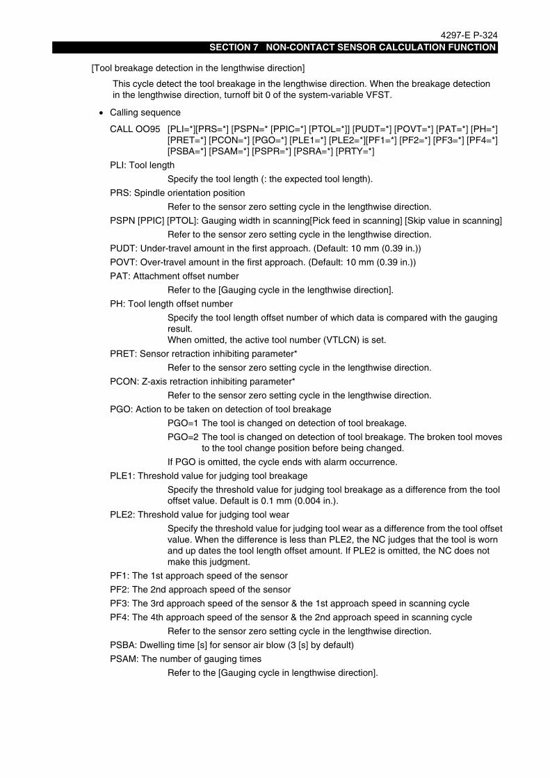
4297-E P-324SECTION 7 NON-CONTACT SENSOR CALCULATION FUNCTION
[Tool breakage detection in the lengthwise direction]
• Calling sequence
This cycle detect the tool breakage in the lengthwise direction. When the breakage detection in the lengthwise direction, turnoff bit 0 of the system-variable VFST.
CALL OO95 [PLI=*][PRS=*] [PSPN=* [PPIC=*] [PTOL=*]] [PUDT=*] [POVT=*] [PAT=*] [PH=*][PRET=*] [PCON=*] [PGO=*] [PLE1=*] [PLE2=*][PF1=*] [PF2=*] [PF3=*] [PF4=*][PSBA=*] [PSAM=*] [PSPR=*] [PSRA=*] [PRTY=*]
PLI: Tool length
Specify the tool length (: the expected tool length).
PRS: Spindle orientation position
Refer to the sensor zero setting cycle in the lengthwise direction.
PSPN [PPIC] [PTOL]: Gauging width in scanning[Pick feed in scanning] [Skip value in scanning]
Refer to the sensor zero setting cycle in the lengthwise direction.
PUDT: Under-travel amount in the first approach. (Default: 10 mm (0.39 in.))
POVT: Over-travel amount in the first approach. (Default: 10 mm (0.39 in.))
PAT: Attachment offset number
Refer to the [Gauging cycle in the lengthwise direction].
PH: Tool length offset number
Specify the tool length offset number of which data is compared with the gauging result.When omitted, the active tool number (VTLCN) is set.
PRET: Sensor retraction inhibiting parameter*
Refer to the sensor zero setting cycle in the lengthwise direction.
PCON: Z-axis retraction inhibiting parameter*
Refer to the sensor zero setting cycle in the lengthwise direction.
PGO: Action to be taken on detection of tool breakage
PGO=1 The tool is changed on detection of tool breakage.
PGO=2 The tool is changed on detection of tool breakage. The broken tool moves to the tool change position before being changed.
If PGO is omitted, the cycle ends with alarm occurrence.
PLE1: Threshold value for judging tool breakage
Specify the threshold value for judging tool breakage as a difference from the tool offset value. Default is 0.1 mm (0.004 in.).
PLE2: Threshold value for judging tool wear
Specify the threshold value for judging tool wear as a difference from the tool offset value. When the difference is less than PLE2, the NC judges that the tool is worn and up dates the tool length offset amount. If PLE2 is omitted, the NC does not make this judgment.
PF1: The 1st approach speed of the sensor
PF2: The 2nd approach speed of the sensor
PF3: The 3rd approach speed of the sensor & the 1st approach speed in scanning cycle
PF4: The 4th approach speed of the sensor & the 2nd approach speed in scanning cycle
Refer to the sensor zero setting cycle in the lengthwise direction.
PSBA: Dwelling time [s] for sensor air blow (3 [s] by default)
PSAM: The number of gauging times
Refer to the [Gauging cycle in lengthwise direction].

4297-E P-325SECTION 7 NON-CONTACT SENSOR CALCULATION FUNCTION
• Cycle operation
PSPR: Allowable difference between the maximum and the minimum measurements
Refer to the [Gauging cycle in lengthwise direction].
PSRA: Action to be taken when the variation exceeds the allowable range (alarm)
Refer to the [Gauging cycle in lengthwise direction].
PRTY: Action to be taken when the variation exceeds the allowable range (retry)
Refer to the [Gauging cycle in lengthwise direction].
1. The sensor is positioned near the Z-axis positive limit.
2. The sensor is positioned at the Y-axis retract position, if the machine needs retraction of Y-axis before gauging.
3. Spindle orientation is done except for gauging of rotating tool.
4. The sensor advances.
5. The Y-axis is positioned at the sensor position.
6. The X-axis is positioned at the sensor position.
7. The laser shutter opens.
8. Gauging cycle starts. (Sensor air blow is carried out for the 1st gauging.)
9. The Z-axis moves to the sensor position.
10. Scanning cycle starts if the cycle is selected.
11. In the case of several times of gauging, the NC repeats the gauging cycle by the specified number of times.
12. The Z-axis moves to the sensor position.
13. The sensor is positioned near the Z-axis positive limit.*
14. The laser shutter closes.
15. The Y-axis retracts if it is so designed.*
16. The sensor retracts.*
17. The tool breakage or the tool wear are judged.
18. When the tool breakage is detected, the tool is changed according to the PGO setting.
* Positioning to the positive limit by the sequence No.13 is omitted when PCON is specified.Sensor retraction by the sequence No.15 and 16 is omitted when PRET is specified.

4297-E P-326SECTION 7 NON-CONTACT SENSOR CALCULATION FUNCTION
[Tool breakage detection in the radial direction]
• Calling sequence
This cycle detects the tool breakage in the radial direction. For the breakage detection in the radial direction, turn off bit 0 of the system-variable VFST.
CALL OO96 [PRI=*] [PLI=*] [PRS=*] [PSPN=* [PPIC=*] [PTOL=*]] [PIN=*] [PUDT=*] [POVT=*][PAT=*] [PD=*] [PRET=*] [PCON=*] [PGO=*] [PLE1=*] [PLE2=*] [PF1=*] [PF2=*][PF3=*] [PF4=*] [PSBA=*] [PSAM=*] [PSPR=*] [PSRA=*] [PRTY=*]
PLI: Tool lengthSpecify the offset amount of the tool length.
PRI: Cutter radiusSpecify the offset amount of the cutter radius (: the expected offset amount of the cutter radius).
PRS: Spindle orientation positionRefer to the sensor zero setting cycle in the lengthwise direction.
PSPN [PPIC] [PTOL]: Gauging width in scanning [Pick feed in scanning] [Skip value in scanning]Refer to the sensor zero setting cycle in the lengthwise direction.
PIN: Z-axis infeed amountRefer to the sensor zero setting cycle in the lengthwise direction.
PIN: Z-axis infeed amountThe sensor starts gauging by shifting from the starting position in the negative direction by a distance specified with PIN.
PUDT: Under-travel amount in the first approach. (Default: 10 mm (0.39 in.))POVT: Over-travel amount in the first approach. (Default: 10 mm (0.39 in.))PAT: Attachment offset number
Refer to the [Gauging cycle in the lengthwise direction].PD: Cutter radius compensation number
The cutter radius is compared with this value.When omitted, the data of the active tool number (VTLCN) is set.
PRET: Sensor retraction inhibiting parameter*Refer to the sensor zero setting cycle in the lengthwise direction.
PCON: Z-axis retraction inhibiting parameter*Refer to the sensor zero setting cycle in the lengthwise direction.
PGO: Action to be taken on detection of tool breakageRefer to the sensor zero setting cycle in the lengthwise direction and the tool breakage detection cycle.
PLE1: Threshold value for judging tool breakageRefer to the sensor zero setting cycle in the lengthwise direction and the tool breakage detection cycle.
PLE2: Threshold value for judging tool wearRefer to the sensor zero setting cycle in the lengthwise direction and the tool breakage detection cycle.
PF1: The 1st approach speed of the sensorPF2: The 2nd approach speed of the sensorPF3: The 3rd approach speed of the sensor & the 1st approach speed in scanning cyclePF4: The 4th approach speed of the sensor & the 2nd approach speed in scanning cycle
Refer to the sensor zero setting cycle in the lengthwise direction.PSBA: Dwelling time [s] for sensor air blow (3 [s] by default)

4297-E P-327SECTION 7 NON-CONTACT SENSOR CALCULATION FUNCTION
• Cycle operation
PSAM: The number of gauging timesRefer to the [Gauging cycle in lengthwise direction].
PSPR: Allowable difference between the maximum and the minimum measurementsRefer to the [Gauging cycle in lengthwise direction].
PSRA: Action to be taken when the variation exceeds the allowable range (alarm)Refer to the [Gauging cycle in lengthwise direction].
PRTY: Action to be taken when the variation exceeds the allowable range (retry)Refer to the [Gauging cycle in lengthwise direction].
1. The sensor is positioned near the Z-axis positive limit.
2. The sensor is positioned at the Y-axis retract position, if the machine needs retraction of Y-axis before gauging.*3
3. Spindle orientation is done except for gauging of rotating tool.
4. The sensor advances.
5. The Y-axis is positioned at the sensor position.*2
6. The X-axis moves to the under-travel position.*2
7. The Z-axis is positioned at the sensor position. (When PIN is specified, the Z-axis shifts in infeed direction by a distance specified with PIN.)
8. The laser shutter opens.
9. Gauging cycle starts. (Sensor air blow is carried out for the 1st gauging.)
10. The X-axis moves to the sensor position.
11. Scanning cycle starts if the cycle is selected.
12. In the case of several times of gauging, the NC repeats the gauging cycle by the specified number of times.
13. The X-axis moves to the sensor position.*2
14. The sensor is positioned near the Z-axis positive limit.*
15. The laser shutter closes.
16. The Y-axis retracts if it is so designed.*, *3
17. The sensor retracts.*
18. The tool breakage or the tool wear are judged.
19. When the tool breakage is detected, the tool is changed according to the PGO setting.
* Positioning to the positive limit by the sequence No.14 is omitted when PCON is specified.Sensor retraction by the sequence No.16 and 17 is omitted when PRET is specified.
*2 When the sensor position is 1 or 3 (for measurement in Y-axis direction), the Y-axis moves instead of the X-axis in the above steps 6, 10, 13, and the X-axis moves instead of Y-axis in the above step 5.
*3 When the sensor position is 1 or 3 (for measurement in Y-axis direction), Y-axis retraction does not take place.

4297-E P-328SECTION 7 NON-CONTACT SENSOR CALCULATION FUNCTION
[High-speed tool breakage detection]
EIOEMR5S6005R01
• Calling sequence
This cycle detects the tool length breakage.The high-speed tool breakage detection is exe-cuted on the assumption that a broken tool does not interrupt the sensor beam as shown in the right figure.This cycle, however, may not be able to detects light tool breakage.
CALL OO97 [PLI=*] [PRI=*] [PRS=*] [PIN=*] [PUDT=*] [POVT=*] [PAT=*] [PH=*] [PRET=*][PCON=*]
PLI: Tool length
Specify the tool length offset amount. When omitted, the value specified with the offset number is set.
PRI: Cutter radius
Specify the cutter radius compensation amount. When omitted, the value specified with the offset number is set.
PRS: Spindle orientation position
Refer to the sensor zero setting cycle in the lengthwise direction.
PIN: Z-axis infeed amount
The sensor starts gauging by shifting from the starting position in the negative direc-tion by a distance specified with PIN. (Default: 0.2 mm (0.008 in.))
PUDT: Under-travel amount in the first approach. (Default: 50 mm (1.97 in.))
POVT: Over-travel amount in the first approach. (Default: 10 mm (0.39 in.))
PAT: Attachment offset number
Refer to the [Gauging cycle in the lengthwise direction].
PH: Tool offset number
Specify the tool off set number. When omitted, the active tool number (VTLCN) is set.
PRET: Sensor retraction inhibiting parameter*
Refer to the sensor zero setting cycle in the lengthwise direction.
PCON: Z-axis retraction inhibiting parameter*
Refer to the sensor zero setting cycle in the lengthwise direction.

4297-E P-329SECTION 7 NON-CONTACT SENSOR CALCULATION FUNCTION
• Cycle operation
1. The sensor is positioned near the Z-axis positive limit.
2. The sensor is positioned at the Y-axis retract position, if the machine needs retraction of Y-axis before gauging.*3
3. Spindle orientation is done except for gauging of rotating tool.
4. The sensor advances.
5. The Y-axis is positioned at the sensor position.*2
6. The X-axis moves to the under-travel position.*2
7. The Z-axis is positioned at the sensor position. (When PIN is specified, the Z-axis shifts in infeed direction by a distance specified with PIN.)
8. The laser shutter opens.
9. The X-axis skips to the target position (sensor position + over travel position).*2
10. The sensor is positioned near the Z-axis positive limit.*
11. The laser shutter closes.
12. The Y-axis retracts if it is so designed.*, *3
13. The sensor retracts.*
14. The tool breakage is judged.
15. When the tool breakage is detected, the tool is changed according to the PGO setting.
* Positioning to the positive limit by the sequence No.10 is omitted when PCON is specified.Sensor retraction by the sequence No.12 and 13 is omitted when PRET is specified.
*2 When the sensor position is 1 or 3 (for measurement in Y-axis direction), the Y-axis moves instead of X-axis in the above steps 6 and 9, and the X-axis moves instead of Y-axis in the above step 5.
*3 When the sensor position is 1 or 3 (for measurement in Y-axis direction), Y-axis retraction does not take place.

4297-E P-330SECTION 7 NON-CONTACT SENSOR CALCULATION FUNCTION
4. Maker's Subprogram in the Fixed Sensor ModeEeoemr5s6004The sensor mode (fixed/movable) can be switched by bit 3 of the system-variable VFST. When
selecting the fixed sensor mode, turn on bit 3 of the variable.A fixed sensor can gauge a horizontal spindle tool (an attachment tool)or a vertical spindle tool. Thesensor mode (horizontal/vertical) can be switched by bit 6 of the system-variable VFST. For gauginga horizontal spindle tool, turn on bit 6 of the variable.The gauging cycles for vertical and horizontal spindle tools are described below:
EIOEMR5S6006R01

4297-E P-331SECTION 7 NON-CONTACT SENSOR CALCULATION FUNCTION
5. Maker's Subprogram for Gauging a Vertical Spindle Tool in the Fixed Sensor Mode
Eeoemr5s6005Like the gauging program for the movable sensor, the program for gauging a vertical spindle tool bythe fixed sensor consists of the following subroutines:[List of gauging preparation cycle]
[List of gauging cycle]
[List of tool breakage detection cycle]
[Tool change position setting cycle (OO31)]
[Y- axis retract position setting cycle (OO33)]
[Spindlespeed]
[Sensor zero setting cycle in the length wise direction (OO93)]
OO31 Position setting cycle for tool change
OO33 Position setting cycle for Y- axis retract
OO93 Sensor zero setting cycle in the length wise direction
OO94 Sensor zero setting cycle in the radial direction
OO95 Gauging in the length wise direction
OO96 Gauging in the radial direction
OO99 Gauging the sphericity
OO95 Tool breakage detection in the length wise direction
OO96 Tool breakage detection in the radial direction
OO97 High-speed tool breakage detection
Refer to "3. Maker's subprogram in the movable sensor mode" [Tool change position setting cycle (OO31)].
Refer to "3. Maker's subprogram in the movable sensor mode" [Y- axis retract position setting cycle (OO33)]
When performing gauging while rotating the spindle, specify the spindle speed by referring to the speed obtained by the following formula:
S=F/N
Here,S means the actual spindle speed. This is the S command value multiplied by the spindle speed override.F is the actual feedrate. If PFI (the 1st approach speed of the sensor)is not specified with an argument, this value is 2,000 multiplied by the cutting feedrate override. If PFI is specified with an argument, this value is the specified value multiplied by the cutting feedrate override.Additionally, when PF1 is specified with an argument, this is a value calculated by multiplying the commanded value by the cutting feedrate override.N is the number of tool blades.
This cycle determines the sensor position used to gauge the tool length and detect tool break-age.The offset method can be switched by bit 7 of VFST.
Bit 7 of VFST OFF : Relatively position offset
ON : Absolutely position offset
Do not change this setting after you select the offset method here. The gauging results are stored in the system-work coordinates No.20.

4297-E P-332SECTION 7 NON-CONTACT SENSOR CALCULATION FUNCTION
• Calling sequence
• Gauging operation
• Cycle operation
CALL OO93 PAXI=* PLI=* [PRS=*] [PSPN=* [PPIC=*] [PTOL=*]] [PUDT=*] [POVT=*] [PAT=*][PRET=1] [PCON=1] [PF1=*] [PF2=*] [PF3=*] [PF4=*] [PSBA=*]
PAXI: Axis of which zero point is set (bit0: the X-axis, bit1: the Y-axis, bit2: Z-axis)
Normal setting data is PAXI=#04H.
PUDT: Under-travel amount in the first approach. (Default: 50 mm (1.97 in.))
POVT: Over-travel amount in the first approach. (Default: 50 mm (1.97 in.))
PLI: Reference tool length
PRS: Spindle orientation position
PSPN [PPIC] [PTOL]: Gauging width in scanning [Pick feed in scanning] [Skip value in scanning]
PAT: Attachment offset number
PCON: Z-axis retraction inhibiting parameter*
PRET: Sensor retraction inhibiting parameter*
PF1: 1st approach speed of the sensor
PF2: 2nd approach speed of the sensor
PF3: 3rd approach speed of the sensor & 1st approach speed in scanning cycle
PF4: 4th approach speed of the sensor & 2nd approach speed in scanning cycle
PSBA: Dwelling time [s] for sensor air blow (3 [s] by default)
Refer to 4. Maker's subprogram in the movable sensor mode.
1. Install the reference tool.
2. Advance the sensor with M144. (Ensure that the sensor does not interfere with anything.)
3. Turn on the laser with M375. (The laser is turned off by M374.)
4. Locate the tool near the sensor by hand.(Locate the tool in a position where the sensor works by Z-axis movement)
5. Execute the sensor zero setting cycle in automatic or MDI operation mode.
1. The sensor is positioned near the Z-axis positive limit.
2. The sensor is positioned at the Y-axis retract position, if the machine needs retraction of Y-axis before gauging.
3. Spindle orientation is done except for gauging of rotating tool.
4. The sensor advances.
5. The Y-axis is positioned.
6. The X-axis is positioned.
7. The Z-axis moves to the under-travel position.
8. The laser shutter opens.
9. Gauging cycle starts.(Sensor air blow is carried out for the 1st gauging.)
10. The Z-axis moves to the sensor position.
11. Scanning cycle starts if the cycle is selected.
12. The sensor is positioned near the Z-axis positive limit.*
13. The laser shutter closes.
14. The Y-axis retracts if it is so designed.*
15. The sensor retracts.*
* Positioning to the positive limit by the sequence No. 12 is omitted when PCON is specified.Sensor retraction by the sequence No.14 and 15 is omitted when PRET is specified.

4297-E P-333SECTION 7 NON-CONTACT SENSOR CALCULATION FUNCTION
[Sensor zero setting cycle in the radial direction (OO94)]
• Calling sequence
• Gauging operation
This cycle determines the sensor position for gauging the cutter radius and detecting tool breakage.The gauging results are stored in the system work coordinates No.20.
CALL OO94 PAXI=* PRI=* PLI=* [PIN=*] [PRS=*] [PSPN=* [PPIC=*] [PTOL=*]] [PUDT=*][POVT=*] [PAT=*] [PRET=*] [PCON=*] [PF1=*] [PF2=*] [PF3=*] [PF4=*] [PSBA=*]
PAXI: Axis of which zero point is set (bit0: X-axis, bit1: Y-axis, and bit2: Z-axis)
Normal setting is #02H.
PUDT: Under-travel amount in the first approach. (Default: 50 mm (1.97 in.))
POVT: Over-travel amount in the first approach. (Default: 50 mm (1.97 in.))
PRI: Reference cutter radius
PLI: Reference tool length
PIN: Z-axis infeed amount
PRS: Spindle orientation position
PSPN [PPIC] [PTOL]: Gauging width in scanning [Pick feed in scanning] [Skip value in scanning]
PAT: Attachment offset number
PRET: Sensor retraction inhibiting parameter*
PCON: Z-axis retraction inhibiting parameter*
PF1: 1st approach speed of the sensor
PF2: 2nd approach speed of the sensor
PF3: 3rd approach speed of the sensor & 1st approach speed in scanning cycle
PF4: 4th approach speed of the sensor & 2nd approach speed in scanning cycle
Refer to "3. Maker's subprogram in the movable sensor mode".
PSBA: Dwelling time [s] for sensor air blow (3 [s] by default)
1. Install the reference tool.
2. Advance the sensor with M144. (Ensure that the sensor does not interfere with anything.)
3. Turn on the laser with M375. (The laser is turned off by M374.)
4. Locate the tool near the sensor by hand. (Locate the tool in a position where the sensor works by Y-axis movement)
5. Execute the sensor zero setting cycle in automatic or MDI operation mode.

4297-E P-334SECTION 7 NON-CONTACT SENSOR CALCULATION FUNCTION
• Cycle operation
1. The sensor is positioned near the Z-axis positive limit.
2. The sensor is positioned at the Y-axis retract position, if the machine needs retraction of Y-axis before gauging.
3. Spindle orientation is done except for gauging of rotating tool.
4. The sensor advances.
5. The Y-axis is positioned at the gauging starting position.
6. The X-axis moves to the under-travel position.
7. The Z-axis is positioned at the gauging starting position. (When PIN is specified, the Z-axis shifts in infeed direction by a distance specified with PIN.)
8. The laser shutter opens.
9. Gauging cycle starts.(Sensor air blow is carried out for the 1st gauging.)
10. The Y-axis moves to the sensor position.
11. Scanning cycle starts if the cycle is selected.
12. The sensor is positioned near the Z-axis positive limit.*
13. The laser shutter closes.
14. The Y-axis retracts if it is so designed.*
15. The sensor retracts.*
* Positioning to the positive limit by the sequence No.12 is omitted when PCON is specified.Sensor retraction by the sequence No.14 and 15 is omitted when PRET is specified.

4297-E P-335SECTION 7 NON-CONTACT SENSOR CALCULATION FUNCTION
[Gauging in the length wise direction]
• Calling sequence
This cycle gauges the tool length. When gauging the tool length, turn on bit 0 of the system-variable VFST.
CALL OO95 PLI=* [PRS=*] [PSPN=* [PPIC=*] [PTOL=*]] [PUDT=*] [POVT=*] [PAT=*] [PH=*][PRET=*] [PCON=*] [PF1=*] [PF2=*] [PF3=*] [PF4=*] [PSBA=*] [PSAM=*] [PSPR=*] [PSRA=*] [PRTY=*]
PLI: Tool length
PRS: Spindle orientation position
PSPN [PPIC] [PTOL]: Gauging width in scanning [Pick feed in scanning] [Skip value in scanning]
PUDT: Under-travel amount in the first approach. (Default: 10 mm (0.39 in.))
POVT: Over-travel amount in the first approach. (Default: 10 mm (0.39 in.))
PAT: Attachment offset number
PH: Tool length offset number
PRET: Sensor retraction inhibiting parameter*
PCON: Z-axis retraction inhibiting parameter*
PF1: The 1st approach speed of the sensor
PF2: The 2nd approach speed of the sensor
PF3: The 3rd approach speed of the sensor & the 1st approach speed in scanning cycle
PF4: The 4th approach speed of the sensor & the 2nd approach speed in scanning cycle
PSBA: Dwelling time [s] for sensor air blow (3 [s] by default)
PSAM: The number of gauging times
PSPR: Allowable difference between the maximum and the minimum measurements
PSRA: Action to be taken when the variation exceeds the allowable range (alarm)
PRTY: Action to be taken when the variation exceeds the allowable range (retry).
Refer to "3. Maker's subprogram in the movable sensor mode".

4297-E P-336SECTION 7 NON-CONTACT SENSOR CALCULATION FUNCTION
• Cycle operation
1. The sensor is positioned near the Z-axis positive limit.
2. The sensor is positioned at the Y-axis retract position, if the machine needs retraction of Y-axis before gauging.
3. Spindle orientation is done except for gauging of rotating tool.
4. The sensor advances.
5. The Y-axis is positioned at the sensor position.
6. The X-axis is positioned at the sensor position.
7. The laser shutter opens.
8. Gauging cycle starts. (Sensor air blow is carried out for the 1st gauging.)
9. The Z-axis moves to the sensor position.
10. Scanning cycle starts if the cycle is selected.
11. In the case of several times of gauging, the NC repeats the gauging cycle by the specified number of times.
12. The Z-axis moves to the sensor position.
13. The sensor is positioned near the Z-axis positive limit.*
14. The laser shutter closes.
15. The Y-axis retracts if it is so designed.*
16. The sensor retracts.*
* Positioning to the positive limit by the sequence No.13 is omitted when PCON is specified.Sensor retraction by the sequence No.15 and 16 is omitted when PRET is specified.
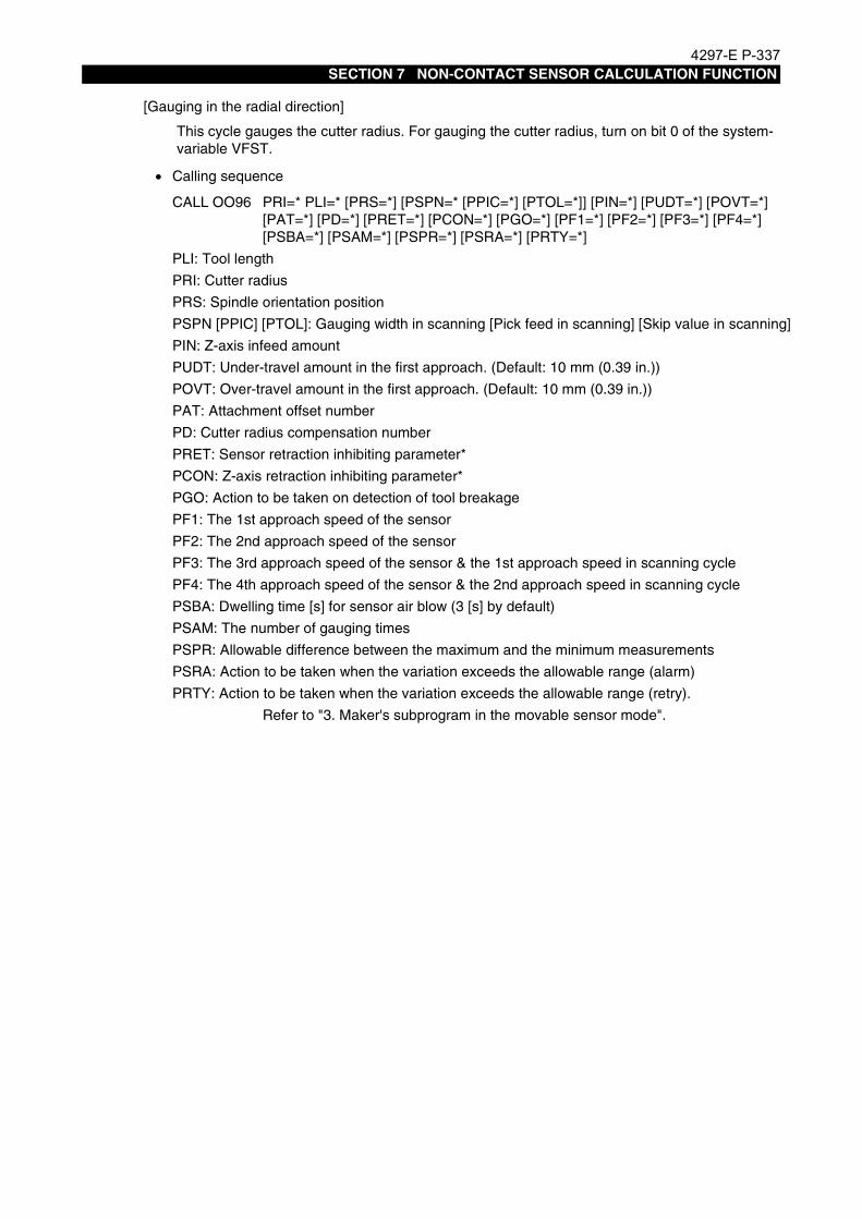
4297-E P-337SECTION 7 NON-CONTACT SENSOR CALCULATION FUNCTION
[Gauging in the radial direction]
• Calling sequence
This cycle gauges the cutter radius. For gauging the cutter radius, turn on bit 0 of the system-variable VFST.
CALL OO96 PRI=* PLI=* [PRS=*] [PSPN=* [PPIC=*] [PTOL=*]] [PIN=*] [PUDT=*] [POVT=*][PAT=*] [PD=*] [PRET=*] [PCON=*] [PGO=*] [PF1=*] [PF2=*] [PF3=*] [PF4=*][PSBA=*] [PSAM=*] [PSPR=*] [PSRA=*] [PRTY=*]
PLI: Tool length
PRI: Cutter radius
PRS: Spindle orientation position
PSPN [PPIC] [PTOL]: Gauging width in scanning [Pick feed in scanning] [Skip value in scanning]
PIN: Z-axis infeed amount
PUDT: Under-travel amount in the first approach. (Default: 10 mm (0.39 in.))
POVT: Over-travel amount in the first approach. (Default: 10 mm (0.39 in.))
PAT: Attachment offset number
PD: Cutter radius compensation number
PRET: Sensor retraction inhibiting parameter*
PCON: Z-axis retraction inhibiting parameter*
PGO: Action to be taken on detection of tool breakage
PF1: The 1st approach speed of the sensor
PF2: The 2nd approach speed of the sensor
PF3: The 3rd approach speed of the sensor & the 1st approach speed in scanning cycle
PF4: The 4th approach speed of the sensor & the 2nd approach speed in scanning cycle
PSBA: Dwelling time [s] for sensor air blow (3 [s] by default)
PSAM: The number of gauging times
PSPR: Allowable difference between the maximum and the minimum measurements
PSRA: Action to be taken when the variation exceeds the allowable range (alarm)
PRTY: Action to be taken when the variation exceeds the allowable range (retry).
Refer to "3. Maker's subprogram in the movable sensor mode".

4297-E P-338SECTION 7 NON-CONTACT SENSOR CALCULATION FUNCTION
• Cycle operation
1. The sensor is positioned near the Z-axis positive limit.
2. The sensor is positioned at the Y-axis retract position, if the machine needs retraction of Y-axis before gauging.
3. Spindle orientation is done except for gauging of rotating tool.
4. The sensor advances.
5. The Y-axis is positioned at the sensor position.
6. The X-axis moves to the under-travel position.
7. The Z-axis is positioned at the sensor position. (When PIN is specified, the Z-axis shifts in infeed direction by a distance specified with PIN.)
8. The laser shutter opens.
9. Gauging cycle starts. (Sensor air blow is carried out for the 1st gauging.)
10. The X-axis moves to the sensor position.
11. Scanning cycle starts if the cycle is selected.
12. In the case of several times of gauging, the NC repeats the gauging cycle by the specified number of times.
13. The X-axis moves to the sensor position.
14. The sensor is positioned near the Z-axis positive limit.*
15. The laser shutter closes.
16. The Y-axis retracts if it is so designed.*
17. The sensor retracts.*
* Positioning to the positive limit by the sequence No.14 is omitted when PCON is specified.Sensor retraction by the sequence No.16 and 17 is omitted when PRET is specified.

4297-E P-339SECTION 7 NON-CONTACT SENSOR CALCULATION FUNCTION
[Gauging the sphericity (OO99)]
• Calling sequence
• Cycle operation
This cycle gauges the sphericity at the tip of a ball end mill.
CALL OO99 [PH=*] [PLI=*] [PRI=*] [PRA=*] [PRS=*] [PUDT=*] [POVT=*] [PAT=*] [PRET=*][PCON=*] [PRE=*] [PF1=*] [PF2=*] [PF3=*] [PF4=*] [PSBA=*]
PH: Tool length offset number, Cutter radius compensation number
PLI: Tool length
PRI: Cutter radius
PRA: The angle added for gauging sphericity
PRS: Spindle orientation position
PUDT: Under-travel amount in the first approach. (Default: 10 mm (0.39 in.))
POVT: Over-travel amount in the first approach. (Default: 10 mm (0.39 in.))
PAT: Attachment offset number
PRET: Sensor retraction inhibiting parameter*
PCON: Z-axis retraction inhibiting parameter*
PRE: Detected error
PF1: The 1st approach speed of the sensor
PF2: The 2nd approach speed of the sensor
PF3: The 3rd approach speed of the sensor & the 1st approach speed in scanning cycle
PF4: The 4th approach speed of the sensor & the 2nd approach speed in scanning cycle
PSBA: Dwelling time [s] for sensor air blow (3 [s] by default)
Refer to "3. Maker's subprogram in the movable sensor mode".
1. The sensor is positioned near the Z-axis positive limit.
2. The sensor is positioned at the Y-axis retract position, if the machine needs retraction of Y-axis before gauging.
3. Spindle orientation is done except for gauging of rotating tool.
4. The sensor advances.
5. The Y-axis is positioned at the sensor position.
6. The X-axis is positioned.
7. The laser shutter opens.
8. Gauging cycle starts. (Sensor air blow is carried out for the 1st gauging.)
9. The X-axis and the Z-axis move to the sensor position.
10. The PRA angle is added and the sensor gauges sphericity in the slanting direction.
11. Operation sequences No.9 and 10 are repeated up to the gauging angle of 90°.12. The X-axis and Z-axis move to the sensor position.
13. The sensor gauges in the radial direction.
14. The sensor is positioned near the Z-axis positive limit.*
15. The laser shutter closes.
16. The Y-axis retracts if it is so designed.*
17. The sensor retracts.*
18. The sphericity is judged, if the judgment command is specified.
* Positioning to the positive limit by the sequence No.14 is omitted when PCON is specified.Sensor retraction by the sequence No.16 and 17 is omitted when PRET is specified.

4297-E P-340SECTION 7 NON-CONTACT SENSOR CALCULATION FUNCTION
[Tool breakage detection in the length wise direction]
• Calling sequence
This cycle detect the tool breakage in the length wise direction. For the breakage detection in the lengthwise direction, turn off bit 0 of the system-variable VFST.
CALL OO95 [PLI=*] [PRS=*] [PSPN=* [PPIC=*] [PTOL=*]] [PUDT=*] [POVT=*] [PAT=*] [PH=*][PRET=*] [PCON=*] [PGO=*] [PLE1=*] [PLE2=*][PF1=*] [PF2=*] [PF3=*] [PF4=*][PSBA=*] [PSAM=*] [PSPR=*] [PSRA=*] [PRTY=*]
PLI: Tool length
PRS: Spindle orientation position
PSPN [PPIC] [PTOL]: Gauging width in scanning [Pick feed in scanning] [Skip value in scanning]
PUDT: Under-travel amount in the first approach. (Default: 10 mm (0.39 in.))
POVT: Over-travel amount in the first approach. (Default: 10 mm (0.39 in.))
PAT: Attachment offset number
PH: Tool length offset number
PRET: Sensor retraction inhibiting parameter*
PCON: Z-axis retraction inhibiting parameter*
PGO: Action to be taken on detection of tool breakage
PLE1: Threshold value for judging tool breakage
PLE2: Threshold value for judging tool wear
PSBA: Dwelling time [s] for sensor air blow (3 [s] by default)
PSAM: The number of gauging times
PSPR: Allowable difference between the maximum and the minimum measurements
PSRA: Action to be taken when the variation exceeds the allowable range (alarm)
PRTY: Action to be taken when the variation exceeds the allowable range (retry).
Refer to "3. Maker's subprogram in the movable sensor mode".

4297-E P-341SECTION 7 NON-CONTACT SENSOR CALCULATION FUNCTION
• Cycle operation
1. The sensor is positioned near the Z-axis positive limit.
2. The sensor is positioned at the Y-axis retract position, if the machine needs retraction of Y-axis before gauging.
3. Spindle orientation is done except for gauging of rotating tool.
4. The sensor advances.
5. The Y-axis is positioned at the sensor position.
6. The X-axis is positioned at the sensor position.
7. The laser shutter opens.
8. Gauging cycle starts. (Sensor air blow is carried out for the 1st gauging.)
9. The Z-axis moves to the sensor position.
10. Scanning cycle starts if the cycle is selected.
11. In the case of several times of gauging, the NC repeats the gauging cycle by the specified number of times.
12. The Z-axis moves to the sensor position.
13. The sensor is positioned near the Z-axis positive limit.*
14. The laser shutter closes.
15. The Y-axis retracts if it is so designed.*
16. The sensor retracts.*
17. The gauging result is judged to be tool breakage or tool wear.
18. When the tool breakage is detected, the tool is changed according to the PGO setting.
* Positioning to the positive limit by the sequence No.13 is omitted when PCON is specified.Sensor retraction by the sequence No.15 and 16 is omitted when PRET is specified.

4297-E P-342SECTION 7 NON-CONTACT SENSOR CALCULATION FUNCTION
[Tool breakage detection in the radial direction]
• Calling sequence
This cycle detects the tool breakage in the radial direction. For thebreakage detection in the radial direction, turn off bit 0 of the system-variable VFST.
CALL OO96 [PRI=*] [PLI=*] [PRS=*] [PSPN=* [PPIC=*] [PTOL=*]] [PIN=*] [PUDT=*] [POVT=*][PAT=*] [PD=*] [PRET=*] [PCON=*] [PGO=*] [PLE1=*] [PLE2=*] [PF1=*] [PF2=*][PF3=*] [PF4=*] [PSBA=*] [PSAM=*] [PSPR=*] [PSRA=*] [PRTY=*]
PLI: Tool length
PRI: Cutter radius
PRS: Spindle orientation position
PSPN [PPIC] [PTOL]: Gauging width in scanning [Pick feed in scanning] [Skip value in scanning]
PIN: Z-axis infeed amount
PUDT: Under-travel amount in the first approach. (Default: 10 mm (0.39 in.))
POVT: Over-travel amount in the first approach. (Default: 10 mm (0.39 in.))
PAT: Attachment offset number
PD: Cutter radius compensation number
PRET: Sensor retraction inhibiting parameter*
PCON: Z-axis retraction inhibiting parameter*
PGO: Action to be taken on detection of tool breakage
PLE1: Threshold value for judging tool breakage
PLE2: Threshold value for judging tool wear
PF1: The 1st approach speed of the sensor
PF2: The 2nd approach speed of the sensor
PF3: The 3rd approach speed of the sensor & the 1st approach speed in scanning cycle
PF4: The 4th approach speed of the sensor & the 2nd approach speed in scanning cycle
PSBA: Dwelling time [s] for sensor air blow (3 [s] by default)
PSAM: The number of gauging times
PSPR: Allowable difference between the maximum and the minimum measurements
PSRA: Action to be taken when the variation exceeds the allowable range (alarm)
PRTY: Action to be taken when the variation exceeds the allowable range (retry).
Refer to "3. Maker's subprogram in the movable sensor mode".

4297-E P-343SECTION 7 NON-CONTACT SENSOR CALCULATION FUNCTION
• Cycle operation
1. The sensor is positioned near the Z-axis positive limit.
2. The sensor is positioned at the Y-axis retract position, if the machine needs retraction of Y-axis before gauging.
3. Spindle orientation is done except for gauging of rotating tool.
4. The sensor advances.
5. The Y-axis is positioned at the sensor position.
6. The X-axis moves to the under-travel position.
7. The Z-axis is positioned at the sensor position. (When PIN is specified, the Z-axis shifts in infeed direction by a distance specified with PIN.)
8. The laser shutter opens.
9. Gauging cycle starts. (Sensor air blow is carried out for the 1st gauging.)
10. The X-axis moves to the sensor position.
11. Scanning cycle starts if the cycle is selected.
12. In the case of several times of gauging, the NC repeats the gauging cycle by the specified number of times.
13. The X-axis moves to the sensor position.
14. The sensor is positioned near the Z-axis positive limit.*
15. The laser shutter closes.
16. The Y-axis retracts if it is so designed.*
17. The sensor retracts.*
18. When the tool breakage is detected, the tool breakage or the tool wear are judged.
19. When the tool breakage is detected, the tool is changed according to the PGO setting.
* Positioning to the positive limit by the sequence No.14 is omitted when PCON is specified.Sensor retraction by the sequence No.16 and 17 is omitted when PRET is specified.

4297-E P-344SECTION 7 NON-CONTACT SENSOR CALCULATION FUNCTION
[High-speed tool breakage detection]
• Calling sequence
• Cycle operation
The tool breakage is detected at high-speed.
CALL OO97 [PLI=*] [PRI=*] [PRS=*] [PIN=*] [PUDT=*] [POVT=*] [PAT=*] [PH=*] [PRET=*][PCON=*]
PLI: Tool length
PRI: Cutter radius
PRS: Spindle orientation position
PIN: Z-axis infeed amount
PUDT: Under-travel amount in the first approach. (Default: 50 mm (1.97 in.))
POVT: Over-travel amount in the first approach. (Default: 10 mm (0.39 in.))
PAT: Attachment offset number
PH: Tool offset number
PRET: Sensor retraction inhibiting parameter*
PCON: Z-axis retraction inhibiting parameter*
Refer to "3. Maker's subprogram in the movable sensor mode".
1. The sensor is positioned near the Z-axis positive limit.
2. The sensor is positioned at the Y-axis retract position, if the machine needs retraction of Y-axis before gauging.
3. Spindle orientation is done except for gauging of rotating tool.
4. The sensor advances.
5. The Y-axis is positioned at the sensor position.
6. The X-axis moves to the under-travel position.
7. The Z-axis is positioned at the sensor position.(When PIN is specified, the Z-axis shifts in infeed direction by a distance specified with PIN.)
8. The laser shutter opens.
9. The X-axis skips to the target position (sensor position + over travel position).
10. The sensor is positioned near the Z-axis positive limit.*
11. The laser shutter closes.
12. The Y-axis retracts if it is so designed.*
13. The sensor retracts.*
14. The gauging result is judged to be tool breakage.
15. When the tool breakage is detected, the tool is changed according to the PGO setting.
* Positioning to the positive limit by the sequence No.10 is omitted when PCON is specified.Sensor retraction by the sequence No.12 and 13 is omitted when PRET is specified.

4297-E P-345SECTION 7 NON-CONTACT SENSOR CALCULATION FUNCTION
6. Maker's Subprogram for Gauging a Horizontal Spindle Tool in the Fixed Sensor Mode
Eeoemr5s6006The sensor mode (fixed/movable)can be switched by bit 3 of the system-variable VFST. Whenselecting the fixed sensor mode, turn on bit 3 of the variable.A fixed sensor can gauge a horizontal spindle tool (an attachment tool)or a vertical spindle tool. Thesensor mode (horizontal/vertical) can be switched by bit 6 of the system-variable VFST. For gauginga horizontal spindle tool, turn on bit 6 of the variable.
EIOEMR5S6007R01
Like the gauging cycles in the movable sensor mode, the horizontal tool gauging program in thefixed sensor mode consists of the following sub routines:[List of gauging preparation cycle]
[List of gauging cycle]
[List of tool breakage detection cycle]
[Tool change position setting cycle (OO31)]
[Z- axis lowering position setting cycle (OO32)]
OO31 Position setting cycle for tool change
OO32 Z- axis lowering position setting cycle
OO93 Sensor zero setting cycle in the length wise direction
OO94 Sensor zero setting cycle in the radial direction
OO95 Gauging in the length wise direction
OO96 Gauging in the radial direction
OO99 Gauging the sphericity
OO95 Tool breakage detection in the length wise direction
OO96 Tool breakage detection in the radial direction
OO97 High-speed tool breakage detection
Refer to "3. Maker's subprogram in the movable sensor mode" [Tool change position setting cycle (OO31)].
For the gauging on extension attachments, the Z-axis lowering position has to been specified. This OO32 cycle set this position. Refer to “Section 1. AUTOMATIC TOOL LENGTH OFFSET / AUTOMATIC TOOL BREAKAGE DETECTION FUNCTION”.

4297-E P-346SECTION 7 NON-CONTACT SENSOR CALCULATION FUNCTION
[Sensor zero setting cycle in the length wise direction (OO93)]
• Calling sequence
• Gauging operation
This cycle determines the sensor position used to gauge the tool length and detect tool break-age.The offset method can be switched by bit 7 of VFST.
Bit 7 of VFST OFF : Relatively position offset
ON : Absolutely position offset
Do not change this setting after you select the offset method here. The gauging results are stored in the system-work coordinates No.23.
CALL OO93 PAXI=* PLI=* [PRS=*] [PSPN=* [PPIC=*] [PTOL=*]] [PUDT=*] [POVT=*]PAT=* [PRET=1] [PCON=1] [PF1=*] [PF2=*] [PF3=*] [PF4=*] [PSBA=*]
PAXI: Axis of which zero point is set (bit0: the X-axis,bit1: the Y-axis, bit2: Z-axis)
Normal setting data is PAXI=#02H.
PLI: Reference tool length
PRS: Spindle orientation position
PSPN [PPIC] [PTOL]: Gauging width in scanning [Pick feed in scanning] [Skip value in scanning]
PUDT: Under-travel amount in the first approach. (Default: 50 mm (1.97 in.))
POVT: Over-travel amount in the first approach. (Default: 50 mm (1.97 in.))
PAT: Attachment offset number
PCON: Z-axis retraction inhibiting parameter*
PRET: Sensor retraction inhibiting parameter*
PF1: 1st approach speed of the sensor
PF2: 2nd approach speed of the sensor
PF3: 3rd approach speed of the sensor & 1st approach speed in scanning cycle
PF4: 4th approach speed of the sensor & 2nd approach speed in scanning cycle
PSBA: Dwelling time [s] for sensor air blow (3 [s] by default)
Refer to "3. Maker's subprogram in the movable sensor mode".
1. Install the reference tool. Set the attachment direction to the right on the user's responsibil-ity.
2. Advance the sensor with M144. (Ensure that the sensor does not interfere with anything.)
3. Turn on the laser with M375. (The laser is turned off by M374.)
4. Locate the tool near the sensor by hand. (Locate the tool in a position where the sensor works by Y-axis movement)
5. Execute the sensor zero setting cycle in automatic or MDI operation mode.

4297-E P-347SECTION 7 NON-CONTACT SENSOR CALCULATION FUNCTION
• Cycle operation
1. The sensor is positioned near the Z-axis positive limit.
2. The Y-axis is positioned at the Z-axis lowering position.
3. Spindle orientation is done except for gauging of rotating tool.
4. The sensor advances.
5. The Z-axis is positioned at the gauging starting position.
6. The Y-axis moves to the under-travel position.
7. The laser shutter opens.
8. Gauging cycle starts. (Sensor air blow is carried out for the 1st gauging.)
9. The Y-axis moves to the sensor position.
10. Scanning cycle starts if the cycle is selected.
11. The Y-axis is positioned at the Z-axis lowering position.
12. The sensor is positioned near the Z-axis positive limit.*
13. The laser shutter closes.
14. The sensor retracts.*
* Positioning to the positive limit by the sequence No.12 is omitted when PCON is specified.Sensor retraction by the sequence No.14 is omitted when PRET is specified.

4297-E P-348SECTION 7 NON-CONTACT SENSOR CALCULATION FUNCTION
[Sensor zero setting cycle in the radial direction (OO94)]
• Calling sequence
• Gauging operation
This cycle determines the sensor position for gauging the cutter radius and detecting the tool breakage. The gauging results are stored in the system work coordinates No.23.
CALL OO94 PAXI=* PRI=* PLI=* [PIN=*] [PRS=*] [PSPN=* [PPIC=*] [PTOL=*]] [PUDT=*][POVT=*] PAT=* [PRET=*] [PCON=*] [PF1=*] [PF2=*] [PF3=*] [PF4=*] [PSBA=*]
PAXI: Axis of which zero point is set (bit0: X-axis, bit1: Y-axis, and bit2: Z-axis)
Normal setting is #04H.
PRI: Reference cutter radius
PLI: Reference tool length
PIN: Z-axis infeed amount
VEST: Sensor setting position
PRS: Spindle orientation position
PSPN [PPIC] [PTOL]: Gauging width in scanning [Pick feed in scanning] [Skip value in scanning]
PUDT: Under-travel amount in the first approach. (Default: 50 mm (1.97 in.))
POVT: Over-travel amount in the first approach. (Default: 50 mm (1.97 in.))
PAT: Attachment offset number
PRET: Sensor retraction inhibiting parameter*
PCON: Z-axis retraction inhibiting parameter*
PF1: 1st approach speed of the sensor
PF2: 2nd approach speed of the sensor
PF3: 3rd approach speed of the sensor & 1st approach speed in scanning cycle
PF4: 4th approach speed of the sensor & 2nd approach speed in scanning cycle
PSBA: Dwelling time [s] for sensor air blow (3 [s] by default)
Refer to "3. Maker's subprogram in the movable sensor mode".
1. Install the reference tool. Set the attachment direction to the right on the user's responsibil-ity.
2. Advance the sensor with M144. (Ensure that the sensor does not interfere with anything.)
3. Turn on the laser with M375. (The laser is turned off by M374.)
4. Locate the tool near the sensor by hand. (Locate the tool in a position where the sensor works by Z-axis movement)
5. Execute the sensor zero setting cycle in automatic or MDI operation mode.

4297-E P-349SECTION 7 NON-CONTACT SENSOR CALCULATION FUNCTION
• Cycle operation
1. The sensor is positioned near the Z-axis positive limit.
2. The Y-axis is positioned at the Z-axis lowering position.
3. Spindle orientation is done except for gauging of rotating tool.
4. The sensor advances.
5. The Z-axis moves to the under-travel position.
6. The Y-axis is positioned at the gauging starting position. (When PIN is specified, the Y-axis shifts in infeed direction by a distance specified with PIN.)
7. The laser shutter opens.
8. Gauging cycle starts. (Sensor air blow is carried out for the 1st gauging.)
9. The Z-axis moves to the sensor position.
10. Scanning cycle starts if the cycle is selected.
11. The Y-axis is positioned at the Z-axis lowering position.
12. The sensor is positioned near the Z-axis positive limit.*
13. The laser shutter closes.
14. The sensor retracts.*
* Positioning to the positive limit by the sequence No.12 is omitted when PCON is specified.Sensor retraction by the sequence No.14 is omitted when PRET is specified.

4297-E P-350SECTION 7 NON-CONTACT SENSOR CALCULATION FUNCTION
[Gauging in the length wise direction]
• Calling sequence
• Cycle operation
This cycle gauges the tool length. When gauging the tool length, turn on bit 0 of the system-variable VFST.
CALL OO95 PLI=* [PRS=*] [PSPN=* [PPIC=*] [PTOL=*]] [PUDT=*] [POVT=*] PAT=* [PH=*][PRET=*] [PCON=*] [PF1=*] [PF2=*] [PF3=*] [PF4=*] [PSBA=*] [PSAM=*] [PSPR=*] [PSRA=*] [PRTY=*]
PLI: Tool length
PRS: Spindle orientation position
PSPN [PPIC] [PTOL]: Gauging width in scanning [Pick feed in scanning][Skip value in scanning]
PUDT: Under-travel amount in the first approach. (Default: 10 mm (0.39 in.))
POVT: Over-travel amount in the first approach. (Default: 10 mm (0.39 in.))
PAT: Attachment off set number
PH: Tool length offset number
PRET: Sensor retraction inhibiting parameter*
PCON: Z-axis retraction inhibiting parameter*
PF1: The 1st approach speed of the sensor
PF2: The 2nd approach speed of the sensor
PF3: The 3rd approach speed of the sensor & the 1st approach speed in scanning cycle
PF4: The 4th approach speed of the sensor & the 2nd approach speed in scanning cycle
PSBA: Dwelling time [s] for sensor air blow (3 [s] by default)
PSAM: The number of gauging times
PSPR: Allowable difference between the maximum and the minimum measurements
PSRA: Action to be taken when the variation exceeds the allowable range (alarm)
PRTY: Action to be taken when the variation exceeds the allowable range (retry).
Refer to "3. Maker's subprogram in the movable sensor mode".
1. The sensor is positioned near the Z-axis positive limit.
2. The Y-axis is positioned at the Z-axis lowering position.
3. Spindle orientation is done except for gauging of rotating tool.
4. The sensor advances.
5. The Z-axis is positioned at the sensor position.
6. The Y-axis is positioned at the under-travel position.
7. The laser shutter opens.
8. Gauging cycle starts. (Sensor air blow is carried out for the 1st gauging.)
9. The Y-axis moves to the sensor position.
10. Scanning cycle starts if the cycle is selected.
11. In the case of several times of gauging, the NC repeats the gauging cycle by the specified number of times.
12. The Y-axis is positioned at the Z-axis lowering position.
13. The sensor is positioned near the Z-axis positive limit.*
14. The laser shutter closes.
15. The sensor retracts.*
* Positioning to the positive limit by the sequence No.13 is omitted when PCON is specified.Sensor retraction by the sequence No.15 is omitted when PRET is specified.

4297-E P-351SECTION 7 NON-CONTACT SENSOR CALCULATION FUNCTION
[Gauging in the radial direction]
• Calling sequence
This cycle gauges the cutter radius. When gauging the cutter radius, turn on bit 0 of the sys-tem-variable VFST.
CALL OO96 PRI=* PLI=* [PRS=*] [PSPN=* [PPIC=*] [PTOL=*]] [PIN=*] [PUDT=*] [POVT=*]PAT=* [PD=*] [PRET=*] [PCON=*] [PGO=*] [PF1=*] [PF2=*] [PF3=*] [PF4=*][PSBA=*] [PSAM=*] [PSPR=*] [PSRA=*] [PRTY=*]
PLI: Tool length
PRI: Cutter radius
PRS: Spindle orientation position
PSPN [PPIC][PTOL]: Gauging width in scanning [Pick feed in scanning] [Skip value in scanning]
PIN: Y-axis infeed amount
PUDT: Under-travel amount in the first approach. (Default: 10 mm (0.39 in.))
POVT: Over-travel amount in the first approach. (Default: 10 mm (0.39 in.))
PAT: Attachment offset number
PD: Cutter radius compensation number
PRET: Sensor retraction inhibiting parameter*
PCON: Z-axis retraction inhibiting parameter*
PF1: The 1st approach speed of the sensor
PF2: The 2nd approach speed of the sensor
PF3: The 3rd approach speed of the sensor & the 1st approach speed in scanning cycle
PF4: The 4th approach speed of the sensor & the 2nd approach speed in scanning cycle
PSBA: Dwelling time [s] for sensor air blow (3 [s] by default)
PSAM: The number of gauging times
PSPR: Allowable difference between the maximum and the minimum measurements
PSRA: Action to be taken when the variation exceeds the allowable range (alarm)
PRTY: Action to be taken when the variation exceeds the allowable range (retry).
Refer to "3. Maker's subprogram in the movable sensor mode".

4297-E P-352SECTION 7 NON-CONTACT SENSOR CALCULATION FUNCTION
• Cycle operation
1. The sensor is positioned near the Z-axis positive limit.
2. The Y-axis is positioned at the Z-axis lowering position.
3. Spindle orientation is done except for gauging of rotating tool.
4. The sensor advances.
5. The Z-axis moves to the under-travel position.
6. The Y-axis is positioned at the sensor position. (When PIN is specified, the Y-axis shifts in infeed direction by a distance specified with PIN.)
7. The laser shutter opens.
8. Gauging cycle starts. (Sensor air blow is carried out for the 1st gauging.)
9. The Z-axis moves to the sensor position.
10. Scanning cycle starts if the cycle is selected.
11. In the case of several times of gauging, the NC repeats the gauging cycle by the specified number of times.
12. The Y-axis is positioned at the Z-axis lowering position.
13. The sensor is positioned near the Z-axis positive limit.*
14. The laser shutter closes.
15. The sensor retracts.*
* Positioning to the positive limit by the sequence No.13 is omitted when PCON is specified.Sensor retraction by the sequence No.15 is omitted when PRET is specified.

4297-E P-353SECTION 7 NON-CONTACT SENSOR CALCULATION FUNCTION
[Gauging the sphericity (OO99)]
• Calling sequence
• Cycle operation
This cycle gauges the sphericity at the tip of a ball end mill.
CALL OO99 [PH=*] [PLI=*] [PRI=*] [PRA=*] [PRS=*] [PUDT=*] [POVT=*] PAT=* [PRET=*][PCON=*] [PRE=*] [PF1=*] [PF2=*] [PF3=*] [PF4=*] [PSBA=*]
PH: Tool length offset number, Cutter radius compensation number
PLI: Tool length
PRI: Cutter radius
PRA: The angle added for gauging sphericity
PRS: Spindle orientation position
PUDT: Under-travel amount in the first approach. (Default: 10 mm (0.39 in.))
POVT: Over-travel amount in the first approach. (Default: 10 mm (0.39 in.))
PAT: Attachment offset number
PRET: Sensor retraction inhibiting parameter*
PCON: Z-axis retraction inhibiting parameter*
PRE: Detected error
PF1: The 1st approach speed of the sensor
PF2: The 2nd approach speed of the sensor
PF3: The 3rd approach speed of the sensor & the 1st approach speed in scanning cycle
PF4: The 4th approach speed of the sensor & the 2nd approach speed in scanning cycle
PSBA: Dwelling time [s] for sensor air blow (3 [s] by default)
Refer to "3. Maker's subprogram in the movable sensor mode".
1. The sensor is positioned near the Z-axis positive limit.
2. The Y-axis is positioned at the Z-axis lowering position.
3. Spindle orientation is done except for gauging of rotating tool.
4. The sensor advances.
5. The Z-axis is positioned at the sensor position.
6. The Y-axis moves to the under-travel position.
7. The laser shutter opens.
8. Gauging cycle starts. (Sensor air blow is carried out for the 1st gauging.)
9. The Y-axis and the Z-axis move to the sensor position.
10. The PRA angle is added and the sensor gauges sphericity in the slanting direction.
11. Operation sequences No.9 and 10 are repeated up to the gauging angle of 90°.12. The Y-axis and Z-axis move to the sensor position.
13. The sensor gauges in the radial direction.
14. The Y-axis is positioned at the Z-axis lowering position.
15. The sensor is positioned near the Z-axis positive limit.*
16. The laser shutter closes.
17. The sensor retracts.*
18. The sphericity is judged, if the judgment command is specified.
* Positioning to the positive limit by the sequence No.15 is omitted when PCON is specified.Sensor retraction by the sequence No.17 is omitted when PRET is specified.

4297-E P-354SECTION 7 NON-CONTACT SENSOR CALCULATION FUNCTION
[Tool breakage detection in the lengthwise direction]
• Calling sequence
This cycle detect the tool breakage in the lengthwise direction. When the breakage detection in the lengthwise direction, turn off bit 0 of the system-variable VFST.
CALL OO95 [PLI=*][PRS=*] [PSPN=* [PPIC=*] [PTOL=*]] [PUDT=*] [POVT=*] PAT=* [PH=*][PRET=*] [PCON=*] [PGO=*] [PLE1=*] [PLE2=*][PF1=*] [PF2=*] [PF3=*] [PF4=*][PSBA=*] [PSAM=*] [PSPR=*] [PSRA=*] [PRTY=*]
PLI: Tool length
PRS: Spindle orientation position
PSPN [PPIC] [PTOL]: Gauging width in scanning [Pick feed in scanning] [Skip value in scanning]
PUDT: Under-travel amount in the first approach. (Default: 10 mm (0.39 in.))
POVT: Over-travel amount in the first approach. (Default: 10 mm (0.39 in.))
PAT: Attachment offset number
PH: Tool length offset number
PRET: Sensor retraction inhibiting parameter*
PCON: Z-axis retraction inhibiting parameter*
PGO: Action to be taken on detection of tool breakage
PLE1: Threshold value for judging tool breakage
PLE2: Threshold value for judging tool wear
PSBA: Dwelling time [s] for sensor air blow (3 [s] by default)
PSAM: The number of gauging times
PSPR: Allowable difference between the maximum and the minimum measurements
PSRA: Action to be taken when the variation exceeds the allowable range (alarm)
PRTY: Action to be taken when the variation exceeds the allowable range (retry).
Refer to "3. Maker's subprogram in the movable sensor mode".

4297-E P-355SECTION 7 NON-CONTACT SENSOR CALCULATION FUNCTION
• Cycle operation
1. The sensor is positioned near the Z-axis positive limit.
2. The Y-axis is positioned at the Z-axis lowering position.
3. Spindle orientation is done except for gauging of rotating tool.
4. The sensor advances.
5. The Z-axis is positioned at the sensor position.
6. The Y-axis moves to the under-travel position.
7. The laser shutter opens.
8. Gauging cycle starts. (Sensor air blow is carried out for the 1st gauging.)
9. The Y-axis moves to the sensor position.
10. Scanning cycle starts if the cycle is selected.
11. The Y-axis is positioned at the Z-axis lowering position.
12. In the case of several times of gauging, the NC repeats the gauging cycle by the specified number of times.
13. The sensor is positioned near the Z-axis positive limit.*
14. The laser shutter closes.
15. The sensor retracts.*
16. The gauging result is judged to be tool breakage or tool wear.
17. When the tool breakage is detected, the tool is changed according to the PGO setting.
* Positioning to the positive limit by the sequence No.13 is omitted when PCON is specified.Sensor retraction by the sequence No.15 is omitted when PRET is specified.

4297-E P-356SECTION 7 NON-CONTACT SENSOR CALCULATION FUNCTION
[Tool breakage detection in the radial direction]
• Calling sequence
This cycle detects the tool breakage in the radial direction. For the breakage detection in the radial direction, turn off bit 0 of the system-variable VFST.
CALL OO96 [PRI=*] [PLI=*] [PRS=*] [PSPN=* [PPIC=*] [PTOL=*]] [PIN=*] [PUDT=*] [POVT=*]PAT=* [PD=*] [PRET=*] [PCON=*] [PGO=*] [PLE1=*] [PLE2=*][PF1=*] [PF2=*][PF3=*] [PF4=*] [PSBA=*] [PSAM=*] [PSPR=*] [PSRA=*] [PRTY=*]
PLI: Tool length
PRI: Cutter radius
PRS: Spindle orientation position
PSPN [PPIC] [PTOL]: Gauging width in scanning [Pick feed in scanning] [Skip value in scanning]
PIN: Y-axis infeed amount
PUDT: Under-travel amount in the first approach. (Default: 10 mm (0.39 in.))
POVT: Over-travel amount in the first approach. (Default: 10 mm (0.39 in.))
PAT: Attachment offset number
PD: Cutter radius compensation number
PRET: Sensor retraction inhibiting parameter*
PCON: Z-axis retraction inhibiting parameter*
PGO: Action to be taken on detection of tool breakage
PLE1: Threshold value for judging tool breakage
PLE2: Threshold value for judging tool wear
PF1: The 1st approach speed of the sensor
PF2: The 2nd approach speed of the sensor
PF3: The 3rd approach speed of the sensor & the 1st approach speed in scanning cycle
PF4: The 4th approach speed of the sensor & the 2nd approach speed in scanning cycle
PSBA: Dwelling time [s] for sensor air blow (3 [s] by default)
PSAM: The number of gauging times
PSPR: Allowable difference between the maximum and the minimum measurements
PSRA: Action to be taken when the variation exceeds the allowable range (alarm)
PRTY: Action to be taken when the variation exceeds the allowable range (retry).
Refer to "3. Maker's subprogram in the movable sensor mode".

4297-E P-357SECTION 7 NON-CONTACT SENSOR CALCULATION FUNCTION
• Cycle operation
1. The sensor is positioned near the Z-axis positive limit.
2. The Y-axis is positioned at the Z-axis lowering position.
3. Spindle orientation is done except for gauging of rotating tool.
4. The sensor advances.
5. The Z-axis moves to the under-travel position.
6. The Y-axis is positioned at the sensor position. (When PIN is specified, the Y-axis is posi-tioned at the shifting point from the sensor position by a distance specified with PIN.)
7. The laser shutter opens.
8. Gauging cycle starts. (Sensor air blow is carried out for the 1st gauging.)
9. The Z-axis moves to the sensor position.
10. Scanning cycle starts if the cycle is selected.
11. In the case of several times of gauging, the NC repeats the gauging cycle by the specified number of times.
12. The Y-axis is positioned at the Z-axis lowering position.
13. The sensor is positioned near the Z-axis positive limit.*
14. The laser shutter closes.
15. The sensor retracts.*
16. If the tool breakage is detected, the NC judges if the tool has been broken or worn.
17. If the judgment is tool breakage, the NC changes the tool according to the PGO setting.
* Positioning to the positive limit by the sequence No.13 is omitted when PCON is specified.Sensor retraction by the sequence No.15 is omitted when PRET is specified.

4297-E P-358SECTION 7 NON-CONTACT SENSOR CALCULATION FUNCTION
[High-speed tool breakage detection]
• Calling sequence
• Cycle operation
The tool breakage is detected at high-speed.
CALL OO97 [PLI=*] [PRI=*] [PRS=*] [PIN=*] [PUDT=*] [POVT=*] PAT=* [PH=*] [PRET=*][PCON=*]
PLI: Tool length
PRI: Cutter radius
PRS: Spindle orientation position
PIN: Y-axis infeed amount
PUDT: Under-travel amount in the first approach. (Default: 50 mm (1.97 in.))
POVT: Over-travel amount in the first approach. (Default: 10 mm (0.39 in.))
PAT: Attachment offset number
PH: Tool offset number
PRET: Sensor retraction inhibiting parameter*
PCON: Z-axis retraction inhibiting parameter*
Refer to "3. Maker's subprogram in the movable sensor mode".
1. The sensor is positioned near the Z-axis positive limit.
2. The Y-axis is positioned at the Z-axis lowering position.
3. Spindle orientation is done except for gauging of rotating tool.
4. The sensor advances.
5. The Z-axis moves to the under-travel position.
6. The Y-axis is positioned at the sensor position. (When PIN is specified, the Y-axis shifts in in feed direction by a distance specified with PIN.)
7. The laser shutter opens.
8. The Z-axis skips to the target position (sensor position + over travel position).
9. The Y-axis is positioned at the Z-axis lowering position.
10. The sensor is positioned near the Z-axis positive limit.*
11. The laser shutter closes.
12. The sensor retracts.*
13. The tool breakage is judged.
14. When the tool breakage is detected, the tool is changed according to the PGO setting.
* Positioning to the positive limit by the sequence No.10 is omitted when PCON is specified.Sensor retraction by the sequence No.12 is omitted when PRET is specified.

4297-E P-359SECTION 7 NON-CONTACT SENSOR CALCULATION FUNCTION
7. List of AlarmsEeoemr5s60072583 Alarm B UNTENDED: Large error in measurement of sphericity
Large errors were detected in measurement of sphericity.[Probable Faulty Locations]In the sensor zero setting cycle, the sensor zero position in the horizontal direction did not match the tool center.Or, the measuring tool was defective.
[Measures to Take]Use a proper tool, such as a spare tool.
2305 Alarm B UNTENDED: Measurement impossible
Measurement became impossible during auto gauging cycle.For this gauging system, the following codes are added to this alarm:
6A Sensor 4 could not be confirmed in the first approach.
6B Contact could not be confirmed in the first approach.
6C Sensor 4 could not be confirmed in the second approach.
6D Contact could not be confirmed in the second approach.
6E Sensor 4 could not be confirmed in the third approach.
6F Contact could not be confirmed in the third approach.
70 Sensor 4 could not be confirmed in the fourth approach.
71 Contact could not be confirmed in the fourth approach.
72 Sensor 4 could not be confirmed in retraction of the skipping cycle.
73 Contact could not be confirmed in the first approach of the skipping cycle.
74 Sensor 4 could not be confirmed in retraction of the skipping cycle.
75 Contact could not be confirmed in the second approach of the skipping cycle.
7B The first sensor could not be confirmed in the high-speed tool breakage detection cycle.
7C The sensor could not be confirmed after skipping in the high-speed tool breakage detection cycle.
95 In the plural measurement operations, the difference between the minimum and maximum measured values exceeded the tolerance.
96 The attachment type does not match the gauging program number.30° angular AT OO125, OO126, OO127, and OO129 are usable.45° angular AT OO115, OO116, OO117, and OO119 are usable.Vertical/Horizontal spindles
In execution of OO95, OO96, OO97, or OO99, no attachment is mounted, or the attachment is not extension one, 90° angular one, or B-/C-axis one.
97 The attachment is not indexed to an angle where measurement is possible.30° angular AT Not indexed to C270°45° angular AT Not indexed to C270°Vertical/Horizontal spindles 90° angular AT not indexed to C270°
B-/C-axis AT indexed to B90° but not indexed to C270°99 The vertical/horizontal spindle tool command (bit 6 of VFST) is wrong.
"1" (horizontal spindle) is set at bit 6 of VFST when no attachment was mounted or an extension AT was mounted for vertical/horizontal spindle measurement. Or, "0" (horizontal spindle) is set at bit 6 of VFST when 90° angular AT or B-/C-axis AT is mounted.

4297-E P-360SECTION 8 NON-CONTACT SENSOR GAUGING FUNCTION FOR HORIZONTAL MC
SECTION 8 NON-CONTACT SENSOR GAUGING FUNC-TION FOR HORIZONTAL MC
1. What is Non-contact Sensor?Eeoemr5s7001The non-contact sensor uses a laser beam for measurement unlike existing sensors with mechani-
cal or electric contacts. This optical sensor, by taking advantages of a non-contact sensor, cangauge even a rotating tool, which used to be impossible for the existing sensors. The sensor canincrease the gauging speed, and can gauge sphericity by taking the advantage of a linear sensor.However, the bloom sensor in tended for linear gauging can not gauge the maximum length (orradial) of an irregular shaped tool depending on the sensor position. Scanning gauging* makes upthis disadvantage. This gauging method permits gauging of a rotating tool or gauging while search-ing the maximum length.
EIOEMR5S7001R01
* Scanning gauging: The sensor gauges a tool in a gauging direction (e.g. the Y-axis) and shifts along the axis at right angles with the gauging axis (e.g. the Z-axis). By repeating the above gauging several times, the sensor determines the maximum tool length (or diameter).

4297-E P-361SECTION 8 NON-CONTACT SENSOR GAUGING FUNCTION FOR HORIZONTAL MC
2. OutlineEeoemr5s7002Non-contact sensor gauging is roughly classified into two methods according to the position where-
the sensor is installed: This gauging function is possible only with the fixed sensor type.
EIOEMR5S7002R01
The sensor mode (fixed/movable) can be switched by bit 3 of the system-variable VFST.
The tool-gauging program consists of the following maker's subprograms:
• Preparation program for gauging
• Gauging program
• Tool breakage detection program
Programs classified by the sensor position are described on the following pages.
3. Gauging with the Fixed SensorEeoemr5s7003Movable sensor and fixed sensor can be switched with the setting at bit 3 of the system variable
VFST. To select the fixed sensor, set ON the bit 3.Perform this gauging by setting OFF the bit 6 of the system variable VFST.
EIOEMR5S7003R01
Bit 3 of VFST 0 ...... Movable sensor
1 ...... Fixed sensor
X+
Y+
Z+
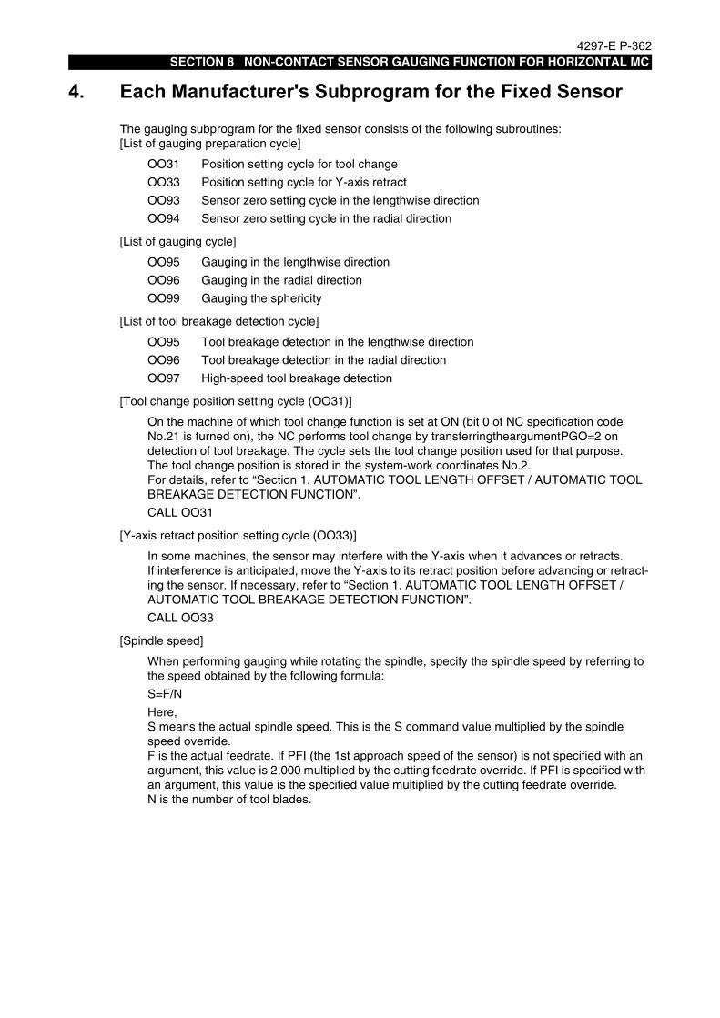
4297-E P-362SECTION 8 NON-CONTACT SENSOR GAUGING FUNCTION FOR HORIZONTAL MC
4. Each Manufacturer's Subprogram for the Fixed SensorEeoemr5s7004The gauging subprogram for the fixed sensor consists of the following subroutines:
[List of gauging preparation cycle]
[List of gauging cycle]
[List of tool breakage detection cycle]
[Tool change position setting cycle (OO31)]
[Y-axis retract position setting cycle (OO33)]
[Spindle speed]
OO31 Position setting cycle for tool change
OO33 Position setting cycle for Y-axis retract
OO93 Sensor zero setting cycle in the lengthwise direction
OO94 Sensor zero setting cycle in the radial direction
OO95 Gauging in the lengthwise direction
OO96 Gauging in the radial direction
OO99 Gauging the sphericity
OO95 Tool breakage detection in the lengthwise direction
OO96 Tool breakage detection in the radial direction
OO97 High-speed tool breakage detection
On the machine of which tool change function is set at ON (bit 0 of NC specification code No.21 is turned on), the NC performs tool change by transferringtheargumentPGO=2 on detection of tool breakage. The cycle sets the tool change position used for that purpose. The tool change position is stored in the system-work coordinates No.2.For details, refer to “Section 1. AUTOMATIC TOOL LENGTH OFFSET / AUTOMATIC TOOL BREAKAGE DETECTION FUNCTION”.
CALL OO31
In some machines, the sensor may interfere with the Y-axis when it advances or retracts.If interference is anticipated, move the Y-axis to its retract position before advancing or retract-ing the sensor. If necessary, refer to “Section 1. AUTOMATIC TOOL LENGTH OFFSET / AUTOMATIC TOOL BREAKAGE DETECTION FUNCTION”.
CALL OO33
When performing gauging while rotating the spindle, specify the spindle speed by referring to the speed obtained by the following formula:
S=F/N
Here,S means the actual spindle speed. This is the S command value multiplied by the spindle speed override.F is the actual feedrate. If PFI (the 1st approach speed of the sensor) is not specified with an argument, this value is 2,000 multiplied by the cutting feedrate override. If PFI is specified with an argument, this value is the specified value multiplied by the cutting feedrate override.N is the number of tool blades.

4297-E P-363SECTION 8 NON-CONTACT SENSOR GAUGING FUNCTION FOR HORIZONTAL MC
[B-axis positioning function]
[Setting a barrier]
[Sensor zero setting cycle in the lengthwise direction (OO93)]
• Calling sequence
This function moves the B-axis to the machine zero before execution of the program for each gauging cycle. Use this function when interference is anticipated between the workpiece and the sensor during gauging.NC optional parameter No. 36 bit 5 (POSITIONING 1: DOES, 0: DOES NOT)
There is an area in which the tool interferes with the sensor when a large-diameter tool is attached to the spindle. A barrier must be set to avoid this.For the setting of a barrier, see the attached manual "SECTION 9 SPECIAL BARRIER FUNC-TION FOR HORIZONTAL MC."
This cycle determines the sensor position used to gauge the tool length and detect tool break-age.The offset method can be switched by bit 7 of VFST.
Bit 7 of VFST OFF : Relatively position offset
ON : Absolutely position offset
Do not change this setting after you select the offset method here. The gauging results are stored in the system-work coordinates No.20.
CALL 0093 PAXI=* PLI=* [PRS=*] [PSPN=* [PPIC=*] [PTOL=*]] [PUDT=*] [POVT=*][PRET=1] [PCON=1] [PF1=*] [PF2=*] [PF3=*] [PF4=*] [PSBA=*]
PAXI: Axis of which zero point is set (bit0: the X-axis, bit1: the Y-axis, bit2: Z-axis)
Normal setting data is PAXI=#05H. In the case of movable sensor, however, set the Y-axis position. Otherwise, the sensor interferes with the tool, damaging the machine.
PUDT: Under-travel amount in the first approach. (Default: 50 mm (1.97 in.))
POVT: Over-travel amount in the first approach. (Default: 50 mm (1.97 in.))
PLI: Reference tool length
For the absolute position offset (as mentioned earlier), specify the length from the gauge line to the end of the reference tool. For the relative position offset, specify the difference between the reference tool length for relative position off-set and the reference tool length used for individual gauging. If they are the same, just specify 0.
PRS: Spindle orientation position
If PRS is omitted and an M code for spindle rotation (M03 or M04) is specified, the tool is measured while in rotation. When PRS is specified, the spindle is ori-ent-stopped and the sensor gauges the stopped tool. With out the above M code, however, the spindle is orient-stopped and the sensor gauges the stopped tool even if PRS is omitted.

4297-E P-364SECTION 8 NON-CONTACT SENSOR GAUGING FUNCTION FOR HORIZONTAL MC
• Gauging operation
PSPN [PPIC] [PTOL]: Gauging width in scanning [Pick feed in scanning] [Skip value in scan-ning]
Specify the width of gauging in one direction. In scanning gauging, the sensor measures the tool in both positive and negative directions. Without designation of PSPN, the sensor cannot gauge the tool. The default pick feed for gauging is 0.1 mm (0.004 in.). Scanning gauging is in tended for determining the maximum tool length position. When the measured value decreased, it is assumed that the subsequent gaug-ing data will no more in crease. This means the sensor does not need to con-tinue gauging before it covers the width of PSPN. The criterion for stopping gauging is called skip value. The default is 0.005 mm (0.00020 in.).
PCON: Z-axis retraction inhibiting parameter*
Usually the Z-axis is positioned near the positive travel limit where the gauging cycle is finished. To hold the Z-axis after gauging, specify "1" for PCON.
PRET: Sensor retraction inhibiting parameter*
Usually the sensor retracts after gauging. To hold the sensor position after gauging, specify "1" for PRET.
* When"1"is set at the Z-axis retract inhibiting parameter, "1"is automatically set also at the sensor retraction inhibiting parameter. This is because the sensor inter-feres with a machine component when it advances or retracts depending on the axis position or the machine.
PF1: 1st approach speed of the sensor
PF2: 2nd approach speed of the sensor
PF3: 3rd approach speed of the sensor & 1st approach speed in scanning cycle
PF4: 4th approach speed of the sensor & 2nd approach speed in scanning cycle
Usually, the tool approaches the sensor four times. In scanning gauging, the tool approaches the sensor twice. Here, specify the approach speed at that time. The default speed is 2,000 mm/min, 1,000 mm/min, 100 mm/min, and 3 mm/min respec-tively. In the case of gauging of a rotating tool, the 4th approach speed depends on rotation speed (0.001 x S [mm]/min).
PSBA: Dwelling time [s] for sensor air blow (3 [s] by default)
1. nstall the reference tool.
2. Advance the sensor with M144. (Ensure that the sensor does not interfere with anything.)
3. Turn on the laser with M375. (The laser is turned off by M374.)
4. Locate the tool near the sensor by hand. (Locate the tool in a position where the sensor works by Z-axis movement)
5. Execute the sensor zero setting cycle in automatic or MDI operation mode.
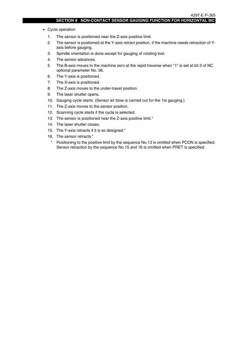
4297-E P-365SECTION 8 NON-CONTACT SENSOR GAUGING FUNCTION FOR HORIZONTAL MC
• Cycle operation
1. The sensor is positioned near the Z-axis positive limit.
2. The sensor is positioned at the Y-axis retract position, if the machine needs retraction of Y-axis before gauging.
3. Spindle orientation is done except for gauging of rotating tool.
4. The sensor advances.
5. The B-axis moves to the machine zero at the rapid traverse when "1" is set at bit 5 of NC optional parameter No. 36.
6. The Y-axis is positioned.
7. The X-axis is positioned.
8. The Z-axis moves to the under-travel position.
9. The laser shutter opens.
10. Gauging cycle starts. (Sensor air blow is carried out for the 1st gauging.)
11. The Z-axis moves to the sensor position.
12. Scanning cycle starts if the cycle is selected.
13. The sensor is positioned near the Z-axis positive limit.*
14. The laser shutter closes.
15. The Y-axis retracts if it is so designed.*
16. The sensor retracts.*
* Positioning to the positive limit by the sequence No.13 is omitted when PCON is specified.Sensor retraction by the sequence No.15 and 16 is omitted when PRET is specified.

4297-E P-366SECTION 8 NON-CONTACT SENSOR GAUGING FUNCTION FOR HORIZONTAL MC
[Sensor zero setting cycle in the radial direction (OO94)]
• Calling sequence
• Gauging operation
This cycle determines the sensor position for gauging the cutter radius and detecting tool breakage.The gauging results are stored in the system work coordinates No.20.
CALL OO94 PAXI=* PRI=* PLI=* [PIN=*] [PRS=*] [PSPN=* [PPIC=*] [PTOL=*]] [PUDT=*][POVT=*] [PRET=*] [PCON=*] [PF1=*] [PF2=*] [PF3=*] [PF4=*] [PSBA=*]
PAXI: Axis of which zero point is set (bit0: X-axis, bit1: Y-axis, and bit2: Z-axis)
Normal setting is #02H.
PUDT: Under-travel amount in the first approach. (Default: 50 mm (1.97 in.))
POVT: Over-travel amount in the first approach. (Default: 50 mm (1.97 in.))
PRI: Reference tool radial
PLI: Reference tool length
PIN: Z-axis infeed amount
PRS: Spindle orientation position
PSPN [PPIC] [PTOL]: Gauging width in scanning [Pick feed in scanning] [Skip value in scanning]
PRET: Sensor retraction inhibiting parameter*
PCON: Z-axis retraction inhibiting parameter*
Refer to the sensor zero setting cycle in the lengthwise direction.
PF1: The 1st approach speed of the sensor
PF2: The 2nd approach speed of the sensor
PF3: The 3rd approach speed of the sensor & the 1st approach speed in scanning cycle
PF4: The 4th approach speed of the sensor & the 2nd approach speed in scanning cycle
Refer to the sensor zero setting cycle in the lengthwise direction.
PSBA: Dwelling time [s] for sensor air blow (3 [s] by default)
1. Install the reference tool.
2. Advance the sensor with M144. (Ensure that the sensor does not interfere with anything.)
3. Turn on the laser with M375. (The laser is turned off by M374.)
4. Locate the tool near the sensor by hand. (Locate the tool in a position where the sensor works by Y-axis movement.)
5. Execute the sensor zero setting cycle in automatic or MDI operation mode.

4297-E P-367SECTION 8 NON-CONTACT SENSOR GAUGING FUNCTION FOR HORIZONTAL MC
• Cycle operation
1. The sensor is positioned near the Z-axis positive limit.
2. The sensor is positioned at the Y-axis retract position, if the machine needs retraction of Y-axis before gauging.
3. Spindle orientation is done except for gauging of rotating tool.
4. The sensor advances.
5. The B-axis moves to the machine zero at the rapid traverse when "1" is set at bit 5 of NC optional parameter No. 36.
6. The Y-axis is positioned at the gauging start position.
7. The X-axis is positioned at the under-travel position.
8. The Z-axis is positioned at the gauging starting position. (When PIN is specified, the Z-axis shifts from the starting position in the negative direction by a distance specified with PIN.)
9. The laser shutter opens.
10. Gauging cycle starts. (Sensor air blow is carried out for the 1st gauging.)
11. The Y-axis moves to the sensor position.
12. Scanning cycle starts if the cycle is selected.
13. The sensor is positioned near the Z-axis positive limit.*
14. The laser shutter closes.
15. The Y-axis retracts if it is so designed.*
16. The sensor retracts.*
* Positioning to the positive limit by the sequence No.13 is omitted when PCON is specified.Sensor retraction by the sequence No.15 and 16 is omitted when PRET is specified.

4297-E P-368SECTION 8 NON-CONTACT SENSOR GAUGING FUNCTION FOR HORIZONTAL MC
[Gauging in the lengthwise direction]
• Calling sequence
This cycle gauges the tool length. When gauging the tool length, turn on bit 0 of the system-variable VFST.
CALL OO95 PLI=* [PRS=*] [PSPN=* [PPIC=*] [PTOL=*]] [PUDT=*] [POVT=*] [PH=*][PRET=*] [PCON=*] [PF1=*] [PF2=*] [PF3=*] [PF4=*] [PSBA=*] [PSAM=*] [PSPR=*] [PSRA=*] [PRTY=*]
PLI: Tool length
PRS: Spindle orientation position
PSPN [PPIC] [PTOL]:Gauging width in scanning [Pick feed in scanning] [Skip value in scanning]
PUDT: Under-travel amount in the first approach. (Default: 10 mm (0.39 in.))
POVT: Over-travel amount in the first approach. (Default: 10 mm (0.39 in.))
PH: Tool length offset number
PRET: Sensor retraction inhibiting parameter*
PCON: Z-axis retraction inhibiting parameter*
PF1: The 1st approach speed of the sensor
PF2: The 2nd approach speed of the sensor
PF3: The 3rd approach speed of the sensor & the 1st approach speed in scanning cycle
PF4: The 4th approach speed of the sensor & the 2nd approach speed in scanning cycle
PSBA: Dwelling time [s] for sensor air blow (3 [s] by default)
Refer to the sensor zero setting cycle in the lengthwise direction.
PSAM: The number of gauging times.
If PSAM is set to 2 or more, the NC repeats the gauging cycle by the set number of times.For the 1st gauging, the NC performs normal gauging (with 4 times of approach).For the 2nd and later gauging cycles, the NC performs gauging by 2 times of approach to the sensor. The approaching speeds in the 2nd and later gauging cycles are as follows:1st approach ... The 3rd approach speed in the normal gauging cycle2nd approach ... The 4th approach speed in the normal gauging cycleThe average value obtained by several times of gauging is regarded as the finally measured value.The 2nd and later gauging cycles do not include the scanning gauging.The default is 3 (times).
PSPR: Allowable difference between the maximum and the minimum measurements
The maximum and the minimum values are obtained from the results of several times of gauging. Set the allowable range of the difference between the maximum and minimum measurements (variation) at this parameter. The default is 0.005 [mm].
PSRA: Action to be taken when the variation exceeds the allowable range (alarm)
Set whether the variation exceeding the allowable range causes an alarm or not.Set "1" if you want an alarm to be generated. Set "0" if not. The default is "0" (no alarm).

4297-E P-369SECTION 8 NON-CONTACT SENSOR GAUGING FUNCTION FOR HORIZONTAL MC
• Cycle operation
PRTY: Action to be taken when the variation exceeds the allowable range (retry).
Set whether the variation exceeding the allowable range triggers another gauging cycle or not. When retry is desired, set the number of retry times at PRTY.If retry is not desired, set "0" at PRTY.The NC performs gauging by the number of times set at PSAM (number of gauging times) for each retry gauging. During the retry gauging, two times of approach is made even in the 1st gauging cycle.If the variation does not fall within the allowable range after the specified number of retrials, an alarm occurs.If PSRA is set to "1", the PRTY value is ignored. If "0" is set at both PSRA and PRTY, the average value is regarded as the measured value even when the varia-tion is out of the allowable range. The default is "0" (no retry).
1. The sensor is positioned near the Z-axis positive limit.
2. The sensor is positioned at the Y-axis retract position, if the machine needs retraction of Y-axis before gauging.
3. Spindle orientation is done except for gauging of rotating tool.
4. The sensor advances.
5. The B-axis moves to the machine zero at the rapid traverse when "1" is set at bit 5 of NC optional parameter No. 36.
6. The X-axis is positioned at the sensor position.
7. The Y-axis is positioned at the sensor position.
8. The sensor-air-blower is turned off.
9. Gauging cycle starts. (Sensor air blow is carried out for the 1st gauging.)
10. The Z-axis moves to the sensor position.
11. Scanning cycle starts if the cycle is selected.
12. In the case of several times of gauging, the NC repeats the gauging cycle by the specified number of times.
13. The Z-axis moves to the sensor position.
14. The sensor is positioned near the Z-axis positive limit.*
15. The laser shutter closes.
16. The Y-axis retracts if it is so designed.*
17. The sensor retracts.*
* Positioning to the positive limit by the sequence No.14 is omitted when PCON is specified.Sensor retraction by the sequence No.16 and 17 is omitted when PRET is specified.

4297-E P-370SECTION 8 NON-CONTACT SENSOR GAUGING FUNCTION FOR HORIZONTAL MC
[Gauging in the radial direction]
• Calling sequence
This cycle gauges the cutter radius. When gauging the cutter radius, turn on bit 0 of the sys-tem-variable VFST.
CALL OO96 PRI=* PLI=* [PRS=*] [PSPN=* [PPIC=*] [PTOL=*]] [PIN=*] [PUDT=*] [POVT=*][PD=*] [PRET=*] [PCON=*] [PGO=*] [PF1=*] [PF2=*] [PF3=*] [PF4=*][PSBA=*] [PSAM=*] [PSPR=*] [PSRA=*] [PRTY=*]
PLI: Tool length
PRI: Cutter radius
PRS: Spindle orientation position
PSPN [PPIC] [PTOL]: Gauging width in scanning [Pick feed in scanning] [Skip value in scanning]
PIN: Z-axis infeed amount
PUDT: Under-travel amount in the first approach. (Default: 10 mm (0.39 in.))
POVT: Over-travel amount in the first approach. (Default: 10 mm (0.39 in.))
PD: Cutter radius compensation number
PRET: Sensor retraction inhibiting parameter*
PCON: Z-axis retraction inhibiting parameter*
PF1: The 1st approach speed of the sensor
PF2: The 2nd approach speed of the sensor
PF3: The 3rd approach speed of the sensor & the 1st approach speed in scanning cycle
PF4: The 4th approach speed of the sensor & the 2nd approach speed in scanning cycle
PSBA: Dwelling time [s] for sensor air blow (3 [s] by default)
PSAM: The number of gauging times
PSPR: Allowable difference between the maximum and the minimum measurements
PSRA: Action to be taken when the variation exceeds the allowable range (alarm)
PRTY: Action to be taken when the variation exceeds the allowable range (retry)
See the description of the zero setting cycle of the sensor for gauging in lengthwise direction and the gauging cycle in lengthwise direction.

4297-E P-371SECTION 8 NON-CONTACT SENSOR GAUGING FUNCTION FOR HORIZONTAL MC
• Cycle operation
1. The sensor is positioned near the Z-axis positive limit.
2. The sensor is positioned at the Y-axis retract position, if the machine needs retraction of Y-axis before gauging.
3. Spindle orientation is done except for gauging of rotating tool.
4. The sensor advances.
5. The B-axis moves to the machine zero at the rapid traverse when "1" is set at bit 5 of NC optional parameter No. 36.
6. The X-axis is positioned at the sensor position.
7. The Y-axis moves to the under-travel position.
8. The Z-axis is positioned at the sensor position. (When PIN is specified, the sensor position shift sin infeed direction by a distance specified with PIN.)
9. The laser shutter opens.
10. Gauging cycle starts. (Sensor air blow is carried out for the 1st gauging.)
11. The X-axis moves to the sensor position.
12. Scanning cycle starts if the cycle is selected.
13. In the case of several times of gauging, the NC repeats the gauging cycle by the specified number of times.
14. The X-axis moves to the sensor position.
15. The sensor is positioned near the Z-axis positive limit.*
16. The laser shutter closes.
17. The Y-axis retracts if it is so designed.*
18. The sensor retracts.*
* Positioning to the positive limit by the sequence No.15 is omitted when PCON is specified.Sensor retraction by the sequence No.17 and 18 is omitted when PRET is specified.

4297-E P-372SECTION 8 NON-CONTACT SENSOR GAUGING FUNCTION FOR HORIZONTAL MC
[Gauging the sphericity (OO99)]
• Calling sequence
This cycle gauges the sphericity at the tip of ball end mill.
CALL OO99 [PH=*] [PLI=*] [PRI=*] [PRA=*] [PRS=*] [PUDT=*] [POVT=*] [PRET=*][PCON=*] [PRE=*] [PF1=*] [PF2=*] [PF3=*] [PF4=*] [PSBA=*]
PH: Tool length offset, cutter radius compensation number
Specify the tool management number where the tool length offset amount and the cutter radius compensation amount are stored for judgment of sphericity. When PH is omitted, the active tool number (VTLCN) is set.
PLI: Tool length
Specify the tool length. When omitted, the offset amount of the tool management number is set.
PRI: Cutter radius
Specify the cutter radius. When omitted, the compensation amount of the tool man-agement number is set.
PRA: The angle added for gauging sphericity
The sensor gauges the sphericity from the length wise direction to the radial direc-tion.Specify the incremental angle used for this gauging. The angle must be 5° or over and a divisor of 90°. Default is 15°.
PRS: Spindle orientation position
PUDT: Under-travel amount in the first approach. (Default: 10 mm (0.39 in.))
POVT: Over-travel amount in the first approach. (Default: 10 mm (0.39 in.))
PRET: Sensor retraction inhibiting parameter*
PCON: Z-axis retraction inhibiting parameter*
PRE: Maximum allowable error
When the error in the sphericity gauging exceeds this amount, an alarm occurs.When PRE is not specified, the cycle does not judge the errors.
PF1: The 1st approach speed of the sensor
PF2: The 2nd approach speed of the sensor
PF3: The 3rd approach speed of the sensor & the 1st approach speed in scanning cycle
PF4: The 4th approach speed of the sensor & the 2nd approach speed in scanning cycle
PSBA: Dwelling time [s] for sensor air blow (3 [s] by default)
Refer to the sensor zero setting cycle in the lengthwise direction.

4297-E P-373SECTION 8 NON-CONTACT SENSOR GAUGING FUNCTION FOR HORIZONTAL MC
• Cycle operation
1. The sensor is positioned near the Z-axis positive limit.
2. The sensor is positioned at the Y-axis retract position, if the machine needs retraction of Y-axis before gauging.
3. Spindle orientation is done except for gauging of rotating tool.
4. The sensor advances.
5. The B-axis moves to the machine zero at the rapid traverse when "1" is set at bit 5 of NC optional parameter No. 36.
6. The X-axis is positioned at the sensor position.
7. The Y-axis is positioned.
8. The laser shutter opens.
9. Gauging cycle starts.(Sensor air blow is carried out for the 1st gauging.)
10. The X-axis and the Z-axis move to the sensor position.
11. The PRA angle is added and the sensor gauges sphericity in the slanting direction.
12. Operation sequences No.9 and 10 are repeated up to the gauging angle of 90°.13. The X-axis and Z-axis move to the sensor position.
14. The sensor gauges in the radial direction.
15. The sensor is positioned near the Z-axis positive limit.*
16. The laser shutter closes.
17. The Y-axis retracts if it is so designed.*
18. The sensor retracts.*
19. The sphericity is judged, if the judgement command is specified.
* Positioning to the positive limit by the sequence No.15 is omitted when PCON is specified.Sensor retraction by the sequence No.17 and 18 is omitted when PRET is specified.

4297-E P-374SECTION 8 NON-CONTACT SENSOR GAUGING FUNCTION FOR HORIZONTAL MC
[Tool breakage detection in the lengthwise direction]
• Calling sequence
This cycle detect the tool breakage in the lengthwise direction. When the breakage detection in the lengthwise direction, turnoff bit 0 of the system-variable VFST.
CALL OO95 [PLI=*][PRS=*] [PSPN=* [PPIC=*] [PTOL=*]] [PUDT=*] [POVT=*] [PH=*][PRET=*] [PCON=*] [PGO=*] [PLE1=*] [PLE2=*][PF1=*] [PF2=*] [PF3=*] [PF4=*][PSBA=*] [PSAM=*] [PSPR=*] [PSRA=*] [PRTY=*]
PLI: Tool length
PRS: Spindle orientation position
PSPN [PPIC] [PTOL]: Gauging width in scanning[Pick feed in scanning] [Skip value in scanning]
PUDT: Under-travel amount in the first approach. (Default: 10 mm (0.39 in.))
POVT: Over-travel amount in the first approach. (Default: 10 mm (0.39 in.))
PH: Tool length offset number
PRET: Sensor retraction inhibiting parameter*
PCON: Z-axis retraction inhibiting parameter*
PGO: Parameter for designating the action when tool breakage is detected
PLE1: Threshold value for judging tool breakage
PLE2: Threshold value for judging tool wear
PSBA: Dwelling time [s] for sensor air blow (3 [s] by default)
Refer to the sensor zero setting cycle in the lengthwise direction.
PSAM: The number of gauging times
PSPR: Allowable difference between the maximum and the minimum measurements
PSRA: Action to be taken when the variation exceeds the allowable range (alarm)
PRTY: Action to be taken when the variation exceeds the allowable range (retry)
See the description of the zero setting cycle of the sensor for gauging in lengthwise direction and the gauging cycle in lengthwise direction.

4297-E P-375SECTION 8 NON-CONTACT SENSOR GAUGING FUNCTION FOR HORIZONTAL MC
• Cycle operation
1. The sensor is positioned near the Z-axis positive limit.
2. The sensor is positioned at the Y-axis retract position, if the machine needs retraction of Y-axis before gauging.
3. Spindle orientation is done except for gauging of rotating tool.
4. The sensor advances.
5. The B-axis moves to the machine zero at the rapid traverse when "1" is set at bit 5 of NC optional parameter No. 36.
6. The X-axis is positioned at the sensor position.
7. The Y-axis is positioned at the sensor position.
8. The laser shutter opens.
9. Gauging cycle starts. (Sensor air blow is carried out for the 1st gauging.)
10. The Z-axis moves to the sensor position.
11. Scanning cycle starts if the cycle is selected.
12. In the case of several times of gauging, the NC repeats the gauging cycle by the specified number of times.
13. The Z-axis moves to the sensor position.
14. The sensor is positioned near the Z-axis positive limit.*
15. The laser shutter closes.
16. The Y-axis retracts if it is so designed.*
17. The sensor retracts.*
18. The tool breakage or the tool wear are judged.
19. When the tool breakage is detected, the tool is changed according to the PGO setting.
* Positioning to the positive limit by the sequence No.14 is omitted when PCON is specified.Sensor retraction by the sequence No.16 and 17 is omitted when PRET is specified.

4297-E P-376SECTION 8 NON-CONTACT SENSOR GAUGING FUNCTION FOR HORIZONTAL MC
[Tool breakage detection in the radial direction]
• Calling sequence
This cycle detects the tool breakage in the radial direction. For the breakage detection in the radial direction, turn off bit 0 of the system-variable VFST.
CALL OO96 [PRI=*] [PLI=*] [PRS=*] [PSPN=* [PPIC=*] [PTOL=*]] [PIN=*] [PUDT=*] [POVT=*][PD=*] [PRET=*] [PCON=*] [PGO=*] [PLE1=*] [PLE2=*] [PF1=*] [PF2=*][PF3=*] [PF4=*] [PSBA=*] [PSAM=*] [PSPR=*] [PSRA=*] [PRTY=*]
PLI: Tool length
PRI: Cutter radius
PRS: Spindle orientation position
PSPN [PPIC] [PTOL]: Gauging width in scanning [Pick feed in scanning] [Skip value in scanning]
PIN: Z-axis infeed amount
PUDT: Under-travel amount in the first approach. (Default: 10 mm (0.39 in.))
POVT: Over-travel amount in the first approach. (Default: 10 mm (0.39 in.))
PD: Cutter radius compensation number
PRET: Sensor retraction inhibiting parameter*
PCON: Z-axis retraction inhibiting parameter*
PGO: Parameter for designating the action when tool breakage is detected
PLE1: Threshold value for judging tool breakage
PLE2: Threshold value for judging tool wear
PF1: The 1st approach speed of the sensor
PF2: The 2nd approach speed of the sensor
PF3: The 3rd approach speed of the sensor & the 1st approach speed in scanning cycle
PF4: The 4th approach speed of the sensor & the 2nd approach speed in scanning cycle
PSBA: Dwelling time [s] for sensor air blow (3 [s] by default)
PSAM: The number of gauging times
PSPR: Allowable difference between the maximum and the minimum measurements
PSRA: Action to be taken when the variation exceeds the allowable range (alarm)
PRTY: Action to be taken when the variation exceeds the allowable range (retry)
See the description of the zero setting cycle of the sensor for gauging in lengthwise direction and the gauging cycle in lengthwise direction.

4297-E P-377SECTION 8 NON-CONTACT SENSOR GAUGING FUNCTION FOR HORIZONTAL MC
• Cycle operation
1. The sensor is positioned near the Z-axis positive limit.
2. The sensor is positioned at the Y-axis retract position, if the machine needs retraction of Y-axis before gauging.
3. Spindle orientation is done except for gauging of rotating tool.
4. The sensor advances.
5. The B-axis moves to the machine zero at the rapid traverse when "1" is set at bit 5 of NC optional parameter No. 36.
6. The X-axis is positioned at the sensor position.
7. The Y-axis moves to the under-travel position.
8. The Z-axis is positioned at the sensor position. (When PIN is specified, the Z-axis shifts in infeed direction by a distance specified with PIN.)
9. The laser shutter opens.
10. Gauging cycle starts. (Sensor air blow is carried out for the 1st gauging.)
11. The X-axis moves to the sensor position.
12. Scanning cycle starts if the cycle is selected.
13. In the case of several times of gauging, the NC repeats the gauging cycle by the specified number of times.
14. The X-axis moves to the sensor position.
15. The sensor is positioned near the Z-axis positive limit.*
16. The laser shutter closes.
17. The Y-axis retracts if it is so designed.*
18. The sensor retracts.*
19. The tool breakage or the tool wear are judged.
20. When the tool breakage is detected, the tool is changed according to the PGO setting.
* Positioning to the positive limit by the sequence No.15 is omitted when PCON is specified.Sensor retraction by the sequence No.17 and 18 is omitted when PRET is specified.

4297-E P-378SECTION 8 NON-CONTACT SENSOR GAUGING FUNCTION FOR HORIZONTAL MC
[High-speed tool breakage detection]
EIOEMR5S7005R01
• Calling sequence
This cycle measures the tool length for detecting broken tool at high speed. The high-speed tool breakage detection is executed on the assumption that a broken tool does not interrupt the sensor beam as shown in the right figure.This cycle, however, may not be able to detects light tool breakage.
CALL OO97 [PLI=*] [PRI=*] [PRS=*] [PIN=*] [PUDT=*] [POVT=*] [PH=*] [PRET=*][PCON=*]
PLI: Tool length
Specify the tool length offset amount. When omitted, the value specified with the offset number is set.
PRI: Cutter radius
Specify the cutter radius compensation amount. When omitted, the value specified with the offset number is set.
PRS: Spindle orientation position
PIN: Z-axis infeed amount
The sensor starts gauging by shifting from the starting position in the negative direc-tion by a distance specified with PIN. (Default: 0.2 mm (0.008 in.))
PUDT: Under-travel amount in the first approach. (Default: 50 mm (1.97 in.))
POVT: Over-travel amount in the first approach. (Default: 10 mm (0.39 in.))
PH: Tool offset number
Specify the tool off set number. When omitted, the active tool number (VTLCN) is set.
PRET: Sensor retraction inhibiting parameter*
PCON: Z-axis retraction inhibiting parameter*
Refer to the sensor zero setting cycle in the lengthwise direction.

4297-E P-379SECTION 8 NON-CONTACT SENSOR GAUGING FUNCTION FOR HORIZONTAL MC
• Cycle operation
1. The sensor is positioned near the Z-axis positive limit.
2. The sensor is positioned at the Y-axis retract position, if the machine needs retraction of Y-axis before gauging.
3. Spindle orientation is done except for gauging of rotating tool.
4. The sensor advances.
5. The B-axis moves to the machine zero at the rapid traverse when "1" is set at bit 5 of NC optional parameter No. 36.
6. The X-axis is positioned at the sensor position.
7. The Y-axis moves to the under-travel position.
8. The Z-axis is positioned at the sensor position. (When PIN is specified, the Z-axis shifts in infeed direction by a distance specified with PIN.)
9. The laser shutter opens.
10. The X-axis skips to the target position (sensor position + over travel position).
11. The sensor is positioned near the Z-axis positive limit.*
12. The laser shutter closes.
13. The Y-axis retracts if it is so designed.*
14. The sensor retracts.*
15. The tool breakage is judged.
16. When the tool breakage is detected, the tool is changed according to the PGO setting.
* Positioning to the positive limit by the sequence No.11 is omitted when PCON is specified.Sensor retraction by the sequence No.13 and 14 is omitted when PRET is specified.

4297-E P-380SECTION 8 NON-CONTACT SENSOR GAUGING FUNCTION FOR HORIZONTAL MC
5. List of AlarmsEeoemr5s70052583 Alarm B UNTENDED: Large error in measurement of sphericity
Large errors were detected in measurement of sphericity.[Probable Faulty Locations]In the sensor zero setting cycle, the sensor zero position in the horizontal direction did not match the tool center.Or, the measuring tool was defective.
[Measures to Take]Use a proper tool, such as a spare tool.
2305 Alarm B UNTENDED: Measurement impossible
Measurement became impossible during auto gauging cycle.For this gauging system, the following codes are added to this alarm:
6A Sensor 4 could not be confirmed in the first approach.
6B Contact could not be confirmed in the first approach.
6C Sensor 4 could not be confirmed in the second approach.
6D Contact could not be confirmed in the second approach.
6E Sensor 4 could not be confirmed in the third approach.
6F Contact could not be confirmed in the third approach.
70 Sensor 4 could not be confirmed in the fourth approach.
71 Contact could not be confirmed in the fourth approach.
72 Sensor 4 could not be confirmed in retraction of the skipping cycle.
73 Contact could not be confirmed in the first approach of the skipping cycle.
74 Sensor 4 could not be confirmed in retraction of the skipping cycle.
75 Contact could not be confirmed in the second approach of the skipping cycle.
7B The first sensor could not be confirmed in the high-speed tool breakage detection cycle.
7C The sensor could not be confirmed after skipping in the high-speed tool breakage detection cycle.
95 In the plural measurement operations, the difference between the minimum and maximum measured values exceeded the tolerance.

4297-E P-381SECTION 9 SPECIAL BARRIER FUNCTION FOR HORIZONTAL MC
SECTION 9 SPECIAL BARRIER FUNCTION FOR HORI-ZONTAL MC
1. OutlineEeoemr5s8001If a non-contact sensor is mounted on a horizontal MC, there is an area in which the tool interferes
with the sensor when a large-diameter tool is attached to the spindle, and consequently the tool maystrike against the sensor.To prevent the tool from striking against the sensor, a special barrier function is adopted.
This function is intended to limit the X-axis travel depending on the Y-axis position.
2. Detailed Specifications
2-1. Parameter SettingEeoemr5s8002Select the parameter setting mode.
Select [F8] (DISPLAY CHANGE) from the function menu.The DISPLAY CHANGE popup window appears.
(a) If the DISPLAY CHANGE popup window shows BARRIER (X, Y), select it to display the BAR-RIER (X, Y) screen.
(b) If not, select [F1] (MENU CHANGE) from the function menu.The MENU CHANGE popup window appears.Using the page keys or [ ↑ ] [ ↓ ] cursor keys, select BARRIER (X, Y)."When you select [F1] (check mark) from the popup function menu in the MENU CHANGEpopup window, a checkmark is set at BARRIER (X, Y)." In this state, select [F7] (OK) from thepopup function menu in the MENU popup window to exit the MENU CHANGE popup window.The DISPLAY CHANGE popup window is updated, and BARRIER (X, Y) is included in the pop-up window. So, select it to display the BARRIER (X, Y) screen.
EIOEMR5S8001R01

4297-E P-382SECTION 9 SPECIAL BARRIER FUNCTION FOR HORIZONTAL MC
Barrier (X, Y) Effective/Ineffective
P limit, N limit
2-2. Setting ItemsEeoemr5s8003Enable or disable the special barrier function in the upper area of the screen.
When Effective is selected, set the barrier data in the table of the screen lower area.In this table, set an effective range of X- and Y-axes. At "Y", set the range where the X-axis travel islimited, and at "X" set the X-axis travel range.Note that the above X- and Y-axis ranges shall be set in the machine coordinate system.Thus, a barrier alarm will occur when both of the following conditions are met.
• Barrier (X, Y) effective
• The Y-axis position in the machine coordinate system is within the set range.
• The X-axis position in the machine coordinate system is not within the set range.
Effective commands : Effective/Ineffective
Initial setting : Ineffective
Effective commands : SET, ADD
Setting range : -99999.999 to 99999.999
Initial value : 0.000

4297-E P-383SECTION 9 SPECIAL BARRIER FUNCTION FOR HORIZONTAL MC
2-3. Barrier Range Setting ExampleEeoemr5s8004When the parameters are set as shown in Figure 1, the barrier ranges are as shown in Figure 2.
EIOEMR5S8002R01
2-4. Barrier Alarm and Resetting MethodEeoemr5s8005If the sensor enters a barrier range set by the special barrier function, the following alarm occurs:
1203 Alarm A Barrier 2To reset his alarm, select the manual operation mode, enable the pulse handle, and reset the NC.First of all, reset the alarm.After the alarm has been reset, axis movement is possible only with the pulse handle. Move theproblem axis out of the interference range using the pulse handle. At the same time, the pulse han-dle can move all the axes.

4297-E P-384SECTION 9 SPECIAL BARRIER FUNCTION FOR HORIZONTAL MC
3. Alarms
3-1. Alarm AEeoemr5s80061203 Barrier
If a non-contact sensor is mounted on a horizontal MC, there is an area in which the tool interferes with the sensor when a large-diameter tool is attached to the spindle.On the parameter setting screen, set a barrier as the interference range of the X- and Y-axes.When (Barrier Y-axis N limit ≤ Y command value ≤ Barrier Y-axis P limit), the alarm lamp lights in either of the following cases:(Barrier X-axis N limit value ≥ X command value) or(Barrier X-axis P limit value ≤ X command value).[Index]None
[Character-string]None
[Code]2: Special barrier function for horizontal MC
[Probable Faulty Locations]Incorrect X-axis or Y-axis command in the program
[Measures to Take]Review the program.A barrier check does not take place in the manual operation mode. When the barrier alarm lamp is lit, select the manual operation mode and reset the alarm. After resetting, axis movement is possible only with the pulse handle. Move the problem axis out of the barrier range using the pulse handle.

4297-E P-385SECTION 10 NON-CONTACT SENSOR GAUGING FUNCTION FOR MCR-AF
SECTION 10 NON-CONTACT SENSOR GAUGING FUNC-TION FOR MCR-AF
1. What is Non-contact Sensor?Eeoemr5s9001The non-contact sensor uses a laser beam for measurement unlike existing sensors with mechani-
cal or electric contacts. This optical sensor, by taking advantages of a non-contact sensor, cangauge even a rotating tool, which used to be impossible for the existing sensors. The sensor canincrease the gauging speed, and can gauge sphericity by taking the advantage of a linear sensor.However, the bloom sensor in tended for linear gauging can not gauge the maximum length (orradial) of an irregular shaped tool depending on the sensor position. Scanning gauging* makes upthis disadvantage. This gauging method permits gauging of a rotating tool or gauging while search-ing the maximum length.
EIOEMR5S9001R01
* Scanning gauging: The sensor gauges a tool in a gauging direction (e.g. the X-axis)and shifts along the axis at right angles with the gauging axis (e.g. the Z-axis). By repeating the above gauging several times, the sensor determines the maximum tool length (or diameter).

4297-E P-386SECTION 10 NON-CONTACT SENSOR GAUGING FUNCTION FOR MCR-AF
2. OutlineEeoemr5s9002Non-contact sensor gauging is roughly classified into two methods according to the position where-
the sensor is installed: This manufacturer's subprogram (hereinafter called the MSB) is for a fixedsensor and can gauge vertical spindle tools.The sensor mode (fixed/movable) can be switched by bit 3 of the system-variable VFST.
EIOEMR5S9002R01
The tool-gauging program consists of the following maker's subprograms:
• Preparation program for gauging
• Gauging program
• Tool breakage detection program
Programs classified by the sensor position are described on the following pages.
Bit 3 of VFST 0 ...... Movable sensor
1 ...... Fixed sensor

4297-E P-387SECTION 10 NON-CONTACT SENSOR GAUGING FUNCTION FOR MCR-AF
3. Manufacturer's Subprogram for the Fixed SensorEeoemr5s9003The movable sensor and fixed sensor can be switched by changing the setting at bit 3 of the system
variable VFST. To select the fixed sensor, set ON the bit 3 of VFST.Since this MSB is used to gauge the vertical spindle tools, be sure to set OFF bit 6 of a system vari-able VFST.
EIOEMR5S9003R01
Vertical spindle tool gauging is described below.
4. Manufacturer's Subprogram for Gauging Vertical Spindle Tools with the Fixed Sensor
Eeoemr5s9004The subprogram for gauging vertical spindle tools with the fixed sensor consists of the following sub-routines:[List of gauging preparation cycle]
[List of gauging cycle]
[List of tool breakage detection cycle]
[Tool change position setting cycle (OO31)]
OO31 Position setting cycle for tool change
OO120 Position setting cycle for X-axis retract
OO93 Sensor zero setting cycle in the lengthwise direction
OO94 Sensor zero setting cycle in the radial direction
OO95 Gauging in the lengthwise direction
OO96 Gauging in the radial direction
OO99 Gauging the sphericity
OO95 Tool breakage detection in the lengthwise direction
OO96 Tool breakage detection in the radial direction
OO97 High-speed tool breakage detection
On the machine of which tool change function is set at ON (bit 0 of NC specification code No.21 is turned on), the NC performs tool change by transferringtheargumentPGO=2 on detection of tool breakage. The cycle sets the tool change position used for that purpose. The tool change position is stored in the system-work coordinates No.2.For details, refer to “Section 1. AUTOMATIC TOOL LENGTH OFFSET / AUTOMATIC TOOL BREAKAGE DETECTION FUNCTION”.
CALL OO31

4297-E P-388SECTION 10 NON-CONTACT SENSOR GAUGING FUNCTION FOR MCR-AF
[X-axis retract position setting cycle (OO120)] (*Set this subroutine without fail.)
Procedure :
1 Move the X-axis to the position to be set as the X-axis retract position.The positions of the X- and Y-axes do not affect the setting.
2 Select the automatic operation mode and execute the following subprogram:CALL OO120M02
The X-axis does not move even if this program is executed.After this program has been executed, the current X-axis position is registered as the X-axisretract position at the system work coordinate system origin No. 12. It can be checked with sys-tem variable VSZOX [12] on the check display screen.
[Spindle speed]
CAUTION
Use this subroutine when moving the X-axis into the machine after gauging.* Set the X-axis position inside the machine when the ATC door is closed.
When performing gauging while rotating the spindle, specify the spindle speed by referring to the speed obtained by the following formula:
S=F/N
Here,S means the actual spindle speed. This is the S command value multiplied by the spindle speed override.F is the actual feedrate. If PFI (the 1st approach speed of the sensor) is not specified with an argument, this value is 2,000 multiplied by the cutting feedrate override. If PFI is specified with an argument, this value is the specified value multiplied by the cutting feedrate override.N is the number of tool blades.
The laser sensor mounting position of the double-column MC "MCR-AF" is outside the travel limit.That is, gauging is performed in a range out of the control of the soft limit.In the sensor zero setting cycle (OO93 or OO94) of this manufacturer's subprogram, the spindleis positioned in the sensor position, and it is, therefore, necessary for the operator to move it outof the travel limit by manual interrupt.Perform this operation with extreme care because it is very dangerous.

4297-E P-389SECTION 10 NON-CONTACT SENSOR GAUGING FUNCTION FOR MCR-AF
[Sensor zero setting cycle in the lengthwise direction (OO93)]
• Calling sequence
This cycle determines the sensor position used to gauge the tool length and detect tool break-age.The offset method can be switched by bit 7 of VFST.
Bit 7 of VFST OFF : Relatively position offset
ON : Absolutely position offset
Do not change this setting after you select the offset method here. The gauging results are stored in the system-work coordinates No.20.
CALL OO93 PAXI=* PLI=* [PRS=*] [PSPN=* [PPIC=*] [PTOL=*]] [PUDT=*] [POVT=*] [PAT=*] [PF1=*] [PF2=*] [PF3=*] [PF4=*] [PSBA=*]
PAXI: Axis of which zero point is set (bit0: the X-axis, bit1: the Y-axis, bit2: Z-axis)
Normal setting is #04H.
PLI: Reference tool length
For the absolute position offset (as mentioned earlier), specify the length from the gauge line to the end of the reference tool. For the relative position offset, specify the difference between the reference tool length for relative position off-set and the reference tool length used for individual gauging. If they are the same, just specify 0.
PRS: Spindle orientation position
If PRS is omitted and an M code for spindle rotation (M03 or M04) is specified, the tool is measured while in rotation. When PRS is specified, the spindle is ori-ent-stopped and the sensor gauges the stopped tool. With out the above M code, however, the spindle is orient-stopped and the sensor gauges the stopped tool even if PRS is omitted.
PSPN [PPIC] [PTOL]: Gauging width in scanning [Pick feed in scanning] [Skip value in scan-ning]
Specify the width of gauging in one direction. In scanning gauging, the sensor measures the tool in both positive and negative directions. Without designation of PSPN, the sensor cannot gauge the tool. The default pick feed for gauging is 0.1 mm (0.004 in.). Scanning gauging is in tended for determining the maximum tool length position. When the measured value decreased, it is assumed that the subsequent gaug-ing data will no more in crease. This means the sensor does not need to con-tinue gauging before it covers the width of PSPN. The criterion for stopping gauging is called skip value. The default is 0.005 mm (0.00020 in.).

4297-E P-390SECTION 10 NON-CONTACT SENSOR GAUGING FUNCTION FOR MCR-AF
• Gauging operation
PUDT: Under-travel amount in the first approach. (Default: 50 mm (1.97 in.))
POVT: Over-travel amount in the first approach. (Default: 50 mm (1.97 in.))
PAT: Attachment offset number
Set the offset amount to VATSC [185, attachment offset number].Use this number when performing the sensor zero setting cycle using an attachment. This MSB is not applicable to the measurement of horizontal spindle tools and can be used only for gauging of the tool mounted with an extension attachment.
PF1: 1st approach speed of the sensor
PF2: 2nd approach speed of the sensor
PF3: 3rd approach speed of the sensor & 1st approach speed in scanning cycle
PF4: 4th approach speed of the sensor & 2nd approach speed in scanning cycle
Usually, the tool approaches the sensor four times. In scanning gauging, the tool approaches the sensor twice. Here, specify the approach speed at that time. The default speed is 2,000 mm/min, 1,000 mm/min, 100 mm/min, and 3 mm/min respec-tively. In the case of gauging of a rotating tool, the 4th approach speed depends on rotation speed (0.001 x S [mm]/min).
PSBA: Dwelling time [s] for sensor air blow (3 [s] by default)
1. Install the reference tool.
2. Execute the sensor zero setting cycle in automatic or MDI operation mode.

4297-E P-391SECTION 10 NON-CONTACT SENSOR GAUGING FUNCTION FOR MCR-AF
• Cycle operation
1. The laser shutter opens.
2. The sensor advances.
3. The ATC door opens (disabling the Z-axis limit).
4. The program stops on reception of M00.
5. Select the manual interrupt mode and move the reference tool near the sensor.The operator must perform the following operations:
• Turn ON manual interrupt mode.
• Manually move the reference tool close to the sensor (where the laser beam isblocked simply by Z-axis movement).
• Turn OFF manual interrupt mode.
• Press the START button.
6. The shift is canceled.
7. The sensor is positioned near the Z-axis positive limit.
8. The sensor is positioned at the X-axis retract position.
9. Spindle orientation is done except for gauging of rotating tool.
10. The X-axis is positioned.
11. The Z-axis moves to the under-travel position.
12. Gauging cycle starts. (Sensor air blow is carried out for the 1st gauging.)
13. The Z-axis moves to the sensor position.
14. Scanning cycle starts if the cycle is selected.
15. The sensor is positioned near the Z-axis positive limit.
16. The laser shutter closes.
17. The X-axis retracts.
18. The sensor retracts.
19. The ATC door closes (enabling the Z-axis limit).

4297-E P-392SECTION 10 NON-CONTACT SENSOR GAUGING FUNCTION FOR MCR-AF
[Sensor zero setting cycle in the radial direction (OO94)]
• Calling sequence
• Gauging operation
This cycle determines the sensor position for gauging the cutter radius and detecting tool breakage.The gauging results are stored in the system work coordinates No.20.
CALL OO94 PAXI=* PRI=* PLI=* [PIN=*] [PRS=*] [PSPN=* [PPIC=*] [PTOL=*]] [PUDT=*][POVT=*] [PAT=*] [PF1=*] [PF2=*] [PF3=*] [PF4=*] [PSBA=*]
PAXI: Axis of which zero point is set (bit0: X-axis, bit1: Y-axis, and bit2: Z-axis)
Normal setting is #01H.
PRI: Reference tool radial
Specify the cutter radius of the reference tool.
PLI: Reference tool length
Refer to the sensor zero setting cycle in the lengthwise direction.
PIN: Z-axis infeed amount
When the sensor zero setting cycle is executed, the sensor starts gauging by shift-ing from the starting position in the negative direction by a distance specified with PIN.
PRS: Spindle orientation position
Refer to the sensor zero setting cycle in the lengthwise direction.
PSPN [PPIC] [PTOL]: Gauging width in scanning [Pick feed in scanning] [Skip value in scanning]
Refer to the sensor zero setting cycle in the lengthwise direction.
PUDT: Under-travel amount in the first approach. (Default: 50 mm (1.97 in.))
POVT: Over-travel amount in the first approach. (Default: 50 mm (1.97 in.))
PAT: Attachment offset number
Refer to the sensor zero setting cycle in the lengthwise direction.
PF1: The 1st approach speed of the sensor
PF2: The 2nd approach speed of the sensor
PF3: The 3rd approach speed of the sensor & the 1st approach speed in scanning cycle
PF4: The 4th approach speed of the sensor & the 2nd approach speed in scanning cycle
Refer to the sensor zero setting cycle in the lengthwise direction.
PSBA: Dwelling time [s] for sensor air blow (3 [s] by default)
1. Install the reference tool.
2. Execute the sensor zero setting cycle in automatic or MDI operation mode.

4297-E P-393SECTION 10 NON-CONTACT SENSOR GAUGING FUNCTION FOR MCR-AF
• Cycle operation
1. The laser shutter opens.
2. The sensor advances.
3. The ATC door opens (disabling the Z-axis limit).
4. The program stops on reception of M00.
5. Select the manual interrupt mode and move the reference tool near the sensor.The operator must perform the following operations:
• Turn ON manual interrupt mode.
• Manually move the reference tool close to the sensor (where the laser beam isblocked simply by Z-axis movement).
• Turn OFF manual interrupt mode.
• Press the START button.
6. The shift is canceled.
7. The sensor is positioned near the Z-axis positive limit.
8. The sensor is positioned at the X-axis retract position.
9. Spindle orientation is done except for gauging of rotating tool.
10. The X-axis is positioned at the under-travel position.
11. The Z-axis is positioned at the gauging starting position. (When PIN is specified, the Z-axis shifts from the starting position in the negative direction by a distance specified with PIN.)
12. Gauging cycle starts. (Sensor air blow is carried out for the 1st gauging.)
13. The X-axis moves to the sensor position.
14. Scanning cycle starts if the cycle is selected.
15. The sensor is positioned near the Z-axis positive limit.
16. The laser shutter closes.
17. The X-axis retracts.
18. The sensor retracts.
19. The ATC door closes (enabling the Z-axis limit).

4297-E P-394SECTION 10 NON-CONTACT SENSOR GAUGING FUNCTION FOR MCR-AF
[Gauging in the lengthwise direction]
• Calling sequence
This cycle gauges the tool length. When gauging the tool length, turn on bit 0 of the system-variable VFST.
CALL OO95 PLI=* [PRS=*] [PSPN=* [PPIC=*] [PTOL=*]] [PUDT=*] [POVT=*] [PAT=*] [PH=*][PF1=*] [PF2=*] [PF3=*] [PF4=*] [PSBA=*] [PSAM=*] [PSPR=*] [PSRA=*] [PRTY=*]
PLI: Tool length
Specify the (expected) tool length.
PRS: Spindle orientation position
Refer to the sensor zero setting cycle in the lengthwise direction.
PSPN [PPIC] [PTOL]:Gauging width in scanning [Pick feed in scanning] [Skip value in scanning]
Refer to the sensor zero setting cycle in the lengthwise direction.
PUDT: Under-travel amount in the first approach. (Default: 10 mm (0.39 in.))
POVT: Over-travel amount in the first approach. (Default: 10 mm (0.39 in.))
PAT: Attachment offset number
Refer to the sensor zero setting cycle in the lengthwise direction.
PH: Tool length offset number
Specify the tool length offset number where the gauged tool length is stored.When PH is omitted, the active tool offset number (VTLCN) is set.
PF1: The 1st approach speed of the sensor
PF2: The 2nd approach speed of the sensor
PF3: The 3rd approach speed of the sensor & the 1st approach speed in scanning cycle
PF4: The 4th approach speed of the sensor & the 2nd approach speed in scanning cycle
Refer to the sensor zero setting cycle in the lengthwise direction.
PSBA: Dwelling time [s] for sensor air blow (3 [s] by default)
PSAM: The number of gauging times.
If PSAM is set to 2 or more, the NC repeats the gauging cycle by the set number of times.For the 1st gauging, the NC performs normal gauging (with 4 times of approach).For the 2nd and later gauging cycles, the NC performs gauging by 2 times of approach to the sensor. The approaching speeds in the 2nd and later gauging cycles are as follows:1st approach ... The 3rd approach speed in the normal gauging cycle2nd approach ... The 4th approach speed in the normal gauging cycleThe average value obtained by several times of gauging is regarded as the finally measured value.The 2nd and later gauging cycles do not include the scanning gauging.The default is 3 (times).
PSPR: Allowable difference between the maximum and the minimum measurements
The maximum and the minimum values are obtained from the results of several times of gauging. Set the allowable range of the difference between the maximum and minimum measurements (variation) at this parameter. The default is 0.005 [mm].
PSRA: Action to be taken when the variation exceeds the allowable range (alarm)
Set whether the variation exceeding the allowable range causes an alarm or not.Set "1" if you want an alarm to be generated. Set "0" if not. The default is "0" (no alarm).
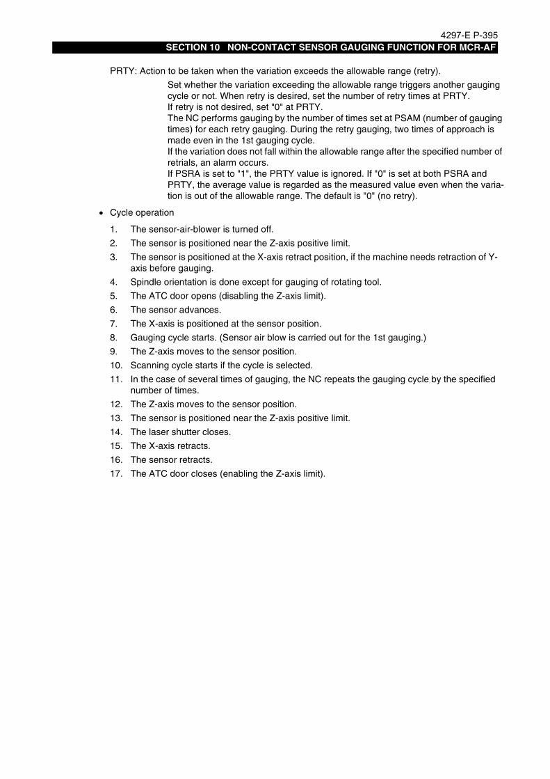
4297-E P-395SECTION 10 NON-CONTACT SENSOR GAUGING FUNCTION FOR MCR-AF
• Cycle operation
PRTY: Action to be taken when the variation exceeds the allowable range (retry).
Set whether the variation exceeding the allowable range triggers another gauging cycle or not. When retry is desired, set the number of retry times at PRTY.If retry is not desired, set "0" at PRTY.The NC performs gauging by the number of times set at PSAM (number of gauging times) for each retry gauging. During the retry gauging, two times of approach is made even in the 1st gauging cycle.If the variation does not fall within the allowable range after the specified number of retrials, an alarm occurs.If PSRA is set to "1", the PRTY value is ignored. If "0" is set at both PSRA and PRTY, the average value is regarded as the measured value even when the varia-tion is out of the allowable range. The default is "0" (no retry).
1. The sensor-air-blower is turned off.
2. The sensor is positioned near the Z-axis positive limit.
3. The sensor is positioned at the X-axis retract position, if the machine needs retraction of Y-axis before gauging.
4. Spindle orientation is done except for gauging of rotating tool.
5. The ATC door opens (disabling the Z-axis limit).
6. The sensor advances.
7. The X-axis is positioned at the sensor position.
8. Gauging cycle starts. (Sensor air blow is carried out for the 1st gauging.)
9. The Z-axis moves to the sensor position.
10. Scanning cycle starts if the cycle is selected.
11. In the case of several times of gauging, the NC repeats the gauging cycle by the specified number of times.
12. The Z-axis moves to the sensor position.
13. The sensor is positioned near the Z-axis positive limit.
14. The laser shutter closes.
15. The X-axis retracts.
16. The sensor retracts.
17. The ATC door closes (enabling the Z-axis limit).

4297-E P-396SECTION 10 NON-CONTACT SENSOR GAUGING FUNCTION FOR MCR-AF
[Gauging in the radial direction]
• Calling sequence
This cycle gauges the cutter radius. When gauging the cutter radius, turn on bit 0 of the sys-tem-variable VFST.
CALL OO96 PRI=* PLI=* [PRS=*] [PSPN=* [PPIC=*] [PTOL=*]] [PIN=*] [PUDT=*] [POVT=*][PAT=*] [PD=*] [PGO=*] [PF1=*] [PF2=*] [PF3=*] [PF4=*][PSBA=*] [PSAM=*] [PSPR=*] [PSRA=*] [PRTY=*]
PLI: Tool length
Specify the offset amount of the tool length.
PRI: Cutter radius
Specify the offset amount of the cutter radius (: the expected offset amount of the cutter radius).
PRS: Spindle orientation position
Refer to the sensor zero setting cycle in the lengthwise direction.
PSPN [PPIC] [PTOL]: Gauging width in scanning [Pick feed in scanning] [Skip value in scanning]
Refer to the sensor zero setting cycle in the lengthwise direction.
PIN: Z-axis infeed amount
The sensor starts gauging by shifting from the starting position in the negative direction by a distance specified with PIN.
PUDT: Under-travel amount in the first approach. (Default: 10 mm (0.39 in.))
POVT: Over-travel amount in the first approach. (Default: 10 mm (0.39 in.))
PAT: Attachment offset number
Refer to the [Gauging cycle in the lengthwise direction].
PD: Cutter radius compensation number
Specify the cutter radius compensation number where is stored the gauged cutter radius.When omitted, the active tool compensation number (VTLCN) is set.
PF1: The 1st approach speed of the sensor
PF2: The 2nd approach speed of the sensor
PF3: The 3rd approach speed of the sensor & the 1st approach speed in scanning cycle
PF4: The 4th approach speed of the sensor & the 2nd approach speed in scanning cycle
Refer to the sensor zero setting cycle in the lengthwise direction.
PSBA: Dwelling time [s] for sensor air blow (3 [s] by default)
PSAM: The number of gauging times
Refer to the [Gauging cycle in lengthwise direction].
PSPR: Allowable difference between the maximum and the minimum measurements
Refer to the [Gauging cycle in lengthwise direction].
PSRA: Action to be taken when the variation exceeds the allowable range (alarm)
Refer to the [Gauging cycle in lengthwise direction].
PRTY: Action to be taken when the variation exceeds the allowable range (retry)
Refer to the [Gauging cycle in lengthwise direction].

4297-E P-397SECTION 10 NON-CONTACT SENSOR GAUGING FUNCTION FOR MCR-AF
• Cycle operation
1. The laser shutter opens.
2. The sensor is positioned near the Z-axis positive limit.
3. The sensor is positioned at the X-axis retract position.
4. Spindle orientation is done except for gauging of rotating tool.
5. The ATC door opens (disabling the Z-axis limit).
6. The sensor advances.
7. The X-axis moves to the under-travel position.
8. The Z-axis is positioned at the sensor position. (When PIN is specified, the sensor position shift sin infeed direction by a distance specified with PIN.)
9. Gauging cycle starts. (Sensor air blow is carried out for the 1st gauging.)
10. The X-axis moves to the sensor position.
11. Scanning cycle starts if the cycle is selected.
12. In the case of several times of gauging, the NC repeats the gauging cycle by the specified number of times.
13. The X-axis moves to the sensor position.
14. The sensor is positioned near the Z-axis positive limit.
15. The laser shutter closes.
16. The X-axis retracts.
17. The sensor retracts.
18. The ATC door closes (enabling the Z-axis limit).

4297-E P-398SECTION 10 NON-CONTACT SENSOR GAUGING FUNCTION FOR MCR-AF
[Gauging the sphericity (OO99)]
• Calling sequence
This cycle gauges the sphericity at the tip of ball end mill.
CALL OO99 [PH=*] [PLI=*] [PRI=*] [PRA=*] [PRS=*] [PUDT=*] [POVT=*] [PAT=*][PRE=*] [PF1=*] [PF2=*] [PF3=*] [PF4=*] [PSBA=*]
PH: Tool length offset, cutter radius compensation number
Specify the tool management number where the tool length offset amount and the cutter radius compensation amount are stored for judgment of sphericity. When PH is omitted, the active tool number (VTLCN) is set.
PLI: Tool length
Specify the tool length. When omitted, the offset amount of the tool management number is set.
PRI: Cutter radius
Specify the cutter radius. When omitted, the compensation amount of the tool man-agement number is set.
PRA: The angle added for gauging sphericity
The sensor gauges the sphericity from the length wise direction to the radial direc-tion.Specify the incremental angle used for this gauging. The angle must be 5° or over and a divisor of 90°. Default is 15°.
PRS: Spindle orientation position
Refer to the sensor zero setting cycle in the lengthwise direction.
PSPN [PPIC] [PTOL]: Gauging width in scanning [Pick feed in scanning][Skip value in scanning]
Refer to the sensor zero setting cycle in the lengthwise direction.
PUDT: Under-travel amount in the first approach. (Default: 10 mm (0.39 in.))
POVT: Over-travel amount in the first approach. (Default: 10 mm (0.39 in.))
PAT: Attachment offset number
Refer to the [Gauging in the lengthwise direction].
PRE: Maximum allowable error
When the error in the sphericity gauging exceeds this amount, an alarm occurs.When PRE is not specified, the cycle does not judge the errors.
PF1: The 1st approach speed of the sensor
PF2: The 2nd approach speed of the sensor
PF3: The 3rd approach speed of the sensor & the 1st approach speed in scanning cycle
PF4: The 4th approach speed of the sensor & the 2nd approach speed in scanning cycle
Refer to the sensor zero setting cycle in the lengthwise direction.
PSBA: Dwelling time [s] for sensor air blow (3 [s] by default)

4297-E P-399SECTION 10 NON-CONTACT SENSOR GAUGING FUNCTION FOR MCR-AF
• Cycle operation
1. The laser shutter opens.
2. The sensor is positioned near the Z-axis positive limit.
3. The sensor is positioned at the X-axis retract position.
4. Spindle orientation is done except for gauging of rotating tool.
5. The ATC door opens (disabling the Z-axis limit).
6. The sensor advances.
7. The X-axis is positioned at the sensor position.
8. Gauging cycle starts.(Sensor air blow is carried out for the 1st gauging.)
9. The X-axis and the Z-axis move to the sensor position.
10. The PRA angle is added and the sensor gauges sphericity in the slanting direction.
11. Operation sequences No.9 and 10 are repeated up to the gauging angle of 90°.12. The X-axis and Z-axis move to the sensor position.
13. The sensor gauges in the radial direction.
14. The sensor is positioned near the Z-axis positive limit.
15. The laser shutter closes.
16. The X-axis retracts.
17. The sensor retracts.
18. The ATC door closes (enabling the Z-axis limit).
19. The sphericity is judged, if the judgement command is specified.

4297-E P-400SECTION 10 NON-CONTACT SENSOR GAUGING FUNCTION FOR MCR-AF
[Tool breakage detection in the lengthwise direction]
• Calling sequence
This cycle detect the tool breakage in the lengthwise direction. When the breakage detection in the lengthwise direction, turnoff bit 0 of the system-variable VFST.
CALL OO95 [PLI=*] [PRS=*] [PSPN=* [PPIC=*] [PTOL=*]] [PUDT=*] [POVT=*] [PAT=*] [PH=*][PGO=*] [PLE1=*] [PLE2=*][PF1=*] [PF2=*] [PF3=*] [PF4=*][PSBA=*] [PSAM=*] [PSPR=*] [PSRA=*] [PRTY=*]
PLI: Tool length
Specify the tool length (: the expected tool length).
PRS: Spindle orientation position
Refer to the sensor zero setting cycle in the lengthwise direction.
PSPN [PPIC] [PTOL]: Gauging width in scanning[Pick feed in scanning] [Skip value in scanning]
Refer to the sensor zero setting cycle in the lengthwise direction.
PUDT: Under-travel amount in the first approach. (Default: 10 mm (0.39 in.))
POVT: Over-travel amount in the first approach. (Default: 10 mm (0.39 in.))
PAT: Attachment offset number
Refer to the [Gauging cycle in the lengthwise direction].
PH: Tool length offset number
Specify the tool length offset number of which data is compared with the gauging result.When omitted, the active tool number (VTLCN) is set.
PGO: Action to be taken on detection of tool breakage
PGO=1 The tool is changed on detection of tool breakage.
PGO=2 The tool is changed on detection of tool breakage. The broken tool moves to the tool change position before being changed.
If PGO is omitted, the cycle ends with alarm occurrence.
PLE1: Threshold value for judging tool breakage
Specify the threshold value for judging tool breakage as a difference from the tool offset value. Default is 0.1 mm (0.004 in.).
PLE2: Threshold value for judging tool wear
Specify the threshold value for judging tool wear as a difference from the tool offset value. When the difference is less than PLE2, the NC judges that the tool is worn and up dates the tool length offset amount. If PLE2 is omitted, the NC does not make this judgment.
PF1: The 1st approach speed of the sensor
PF2: The 2nd approach speed of the sensor
PF3: The 3rd approach speed of the sensor & the 1st approach speed in scanning cycle
PF4: The 4th approach speed of the sensor & the 2nd approach speed in scanning cycle
Refer to the sensor zero setting cycle in the lengthwise direction.
PSBA: Dwelling time [s] for sensor air blow (3 [s] by default)
PSAM: The number of gauging times
Refer to the [Gauging cycle in lengthwise direction].
PSPR: Allowable difference between the maximum and the minimum measurements
Refer to the [Gauging cycle in lengthwise direction].
PSRA: Action to be taken when the variation exceeds the allowable range (alarm)
Refer to the [Gauging cycle in lengthwise direction].
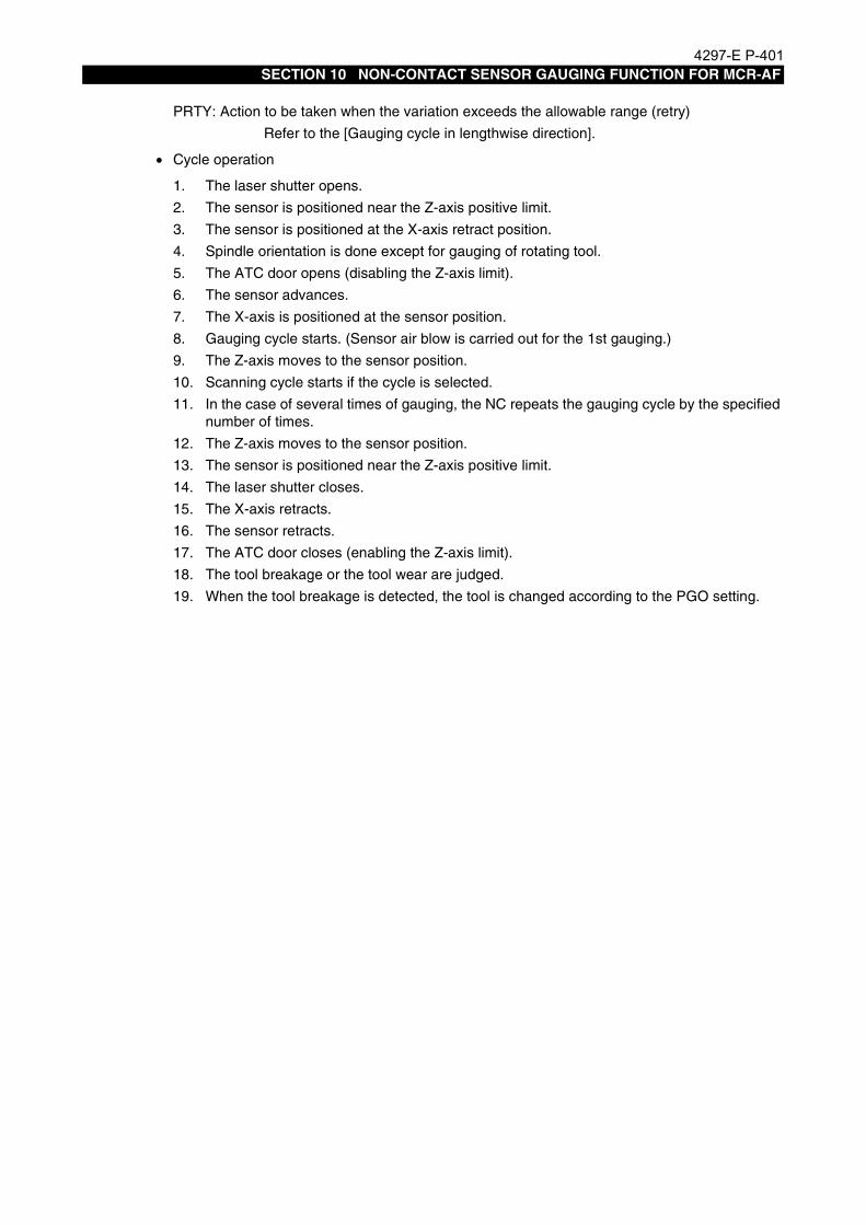
4297-E P-401SECTION 10 NON-CONTACT SENSOR GAUGING FUNCTION FOR MCR-AF
• Cycle operation
PRTY: Action to be taken when the variation exceeds the allowable range (retry)
Refer to the [Gauging cycle in lengthwise direction].
1. The laser shutter opens.
2. The sensor is positioned near the Z-axis positive limit.
3. The sensor is positioned at the X-axis retract position.
4. Spindle orientation is done except for gauging of rotating tool.
5. The ATC door opens (disabling the Z-axis limit).
6. The sensor advances.
7. The X-axis is positioned at the sensor position.
8. Gauging cycle starts. (Sensor air blow is carried out for the 1st gauging.)
9. The Z-axis moves to the sensor position.
10. Scanning cycle starts if the cycle is selected.
11. In the case of several times of gauging, the NC repeats the gauging cycle by the specified number of times.
12. The Z-axis moves to the sensor position.
13. The sensor is positioned near the Z-axis positive limit.
14. The laser shutter closes.
15. The X-axis retracts.
16. The sensor retracts.
17. The ATC door closes (enabling the Z-axis limit).
18. The tool breakage or the tool wear are judged.
19. When the tool breakage is detected, the tool is changed according to the PGO setting.

4297-E P-402SECTION 10 NON-CONTACT SENSOR GAUGING FUNCTION FOR MCR-AF
[Tool breakage detection in the radial direction]
• Calling sequence
This cycle detects the tool breakage in the radial direction. For the breakage detection in the radial direction, turn off bit 0 of the system-variable VFST.
CALL OO96 [PRI=*] [PLI=*] [PRS=*] [PSPN=* [PPIC=*] [PTOL=*]] [PIN=*] [PUDT=*] [POVT=*][PAT=*] [PD=*] [PGO=*] [PLE1=*] [PLE2=*] [PF1=*] [PF2=*][PF3=*] [PF4=*] [PSBA=*] [PSAM=*] [PSPR=*] [PSRA=*] [PRTY=*]
PLI: Tool length
Specify the offset amount of the tool length.
PRI: Cutter radius
Specify the offset amount of the cutter radius (: the expected offset amount of the cutter radius).
PRS: Spindle orientation position
Refer to the sensor zero setting cycle in the lengthwise direction.
PSPN [PPIC] [PTOL]: Gauging width in scanning [Pick feed in scanning] [Skip value in scanning]
Refer to the sensor zero setting cycle in the lengthwise direction.
PIN: Z-axis infeed amount
The sensor starts gauging by shifting from the starting position in the negative direction by a distance specified with PIN.
PUDT: Under-travel amount in the first approach. (Default: 10 mm (0.39 in.))
POVT: Over-travel amount in the first approach. (Default: 10 mm (0.39 in.))
PAT: Attachment offset number
Refer to the [Gauging cycle in the lengthwise direction].
PD: Cutter radius compensation number
The cutter radius is compared with this value.When omitted, the data of the active tool number (VTLCN) is set.
PGO: Action to be taken on detection of tool breakage
Refer to the sensor zero setting cycle in the lengthwise direction and the tool breakage detection cycle.
PLE1: Threshold value for judging tool breakage
Refer to the sensor zero setting cycle in the lengthwise direction and the tool breakage detection cycle.
PLE2: Threshold value for judging tool wear
Refer to the sensor zero setting cycle in the lengthwise direction and the tool breakage detection cycle.
PF1: The 1st approach speed of the sensor
PF2: The 2nd approach speed of the sensor
PF3: The 3rd approach speed of the sensor & the 1st approach speed in scanning cycle
PF4: The 4th approach speed of the sensor & the 2nd approach speed in scanning cycle
Refer to the sensor zero setting cycle in the lengthwise direction.
PSBA: Dwelling time [s] for sensor air blow (3 [s] by default)
PSAM: The number of gauging times
Refer to the [Gauging cycle in lengthwise direction].
PSPR: Allowable difference between the maximum and the minimum measurements
Refer to the [Gauging cycle in lengthwise direction].

4297-E P-403SECTION 10 NON-CONTACT SENSOR GAUGING FUNCTION FOR MCR-AF
• Cycle operation
PSRA: Action to be taken when the variation exceeds the allowable range (alarm)
Refer to the [Gauging cycle in lengthwise direction].
PRTY: Action to be taken when the variation exceeds the allowable range (retry)
Refer to the [Gauging cycle in lengthwise direction].
1. The laser shutter opens.
2. The sensor is positioned near the Z-axis positive limit.
3. The sensor is positioned at the X-axis retract position.
4. Spindle orientation is done except for gauging of rotating tool.
5. The ATC door opens (disabling the Z-axis limit).
6. The sensor advances.
7. The X-axis moves to the under-travel position.
8. The Z-axis is positioned at the sensor position. (When PIN is specified, the Z-axis shifts in infeed direction by a distance specified with PIN.)
9. Gauging cycle starts. (Sensor air blow is carried out for the 1st gauging.)
10. The X-axis moves to the sensor position.
11. Scanning cycle starts if the cycle is selected.
12. In the case of several times of gauging, the NC repeats the gauging cycle by the specified number of times.
13. The X-axis moves to the sensor position.
14. The sensor is positioned near the Z-axis positive limit.
15. The laser shutter closes.
16. The X-axis retracts.
17. The sensor retracts.
18. The ATC door closes (enabling the Z-axis limit).
19. The tool breakage or the tool wear are judged.
20. When the tool breakage is detected, the tool is changed according to the PGO setting.
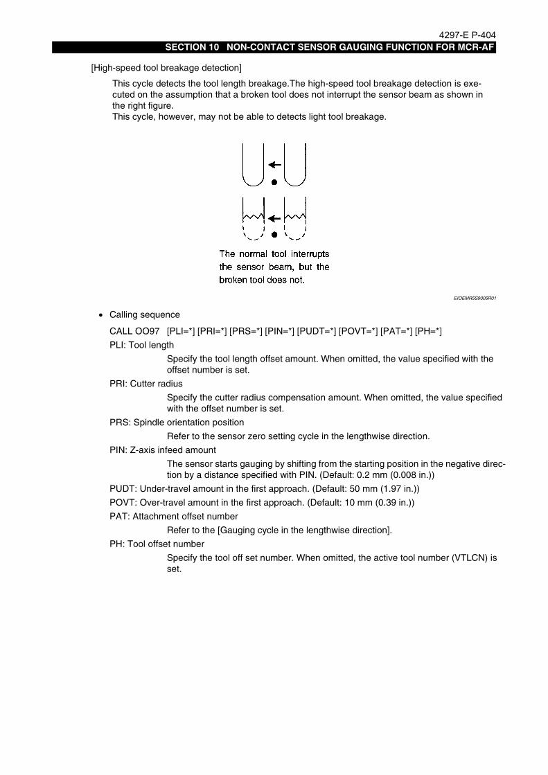
4297-E P-404SECTION 10 NON-CONTACT SENSOR GAUGING FUNCTION FOR MCR-AF
[High-speed tool breakage detection]
EIOEMR5S9005R01
• Calling sequence
This cycle detects the tool length breakage.The high-speed tool breakage detection is exe-cuted on the assumption that a broken tool does not interrupt the sensor beam as shown in the right figure.This cycle, however, may not be able to detects light tool breakage.
CALL OO97 [PLI=*] [PRI=*] [PRS=*] [PIN=*] [PUDT=*] [POVT=*] [PAT=*] [PH=*]
PLI: Tool length
Specify the tool length offset amount. When omitted, the value specified with the offset number is set.
PRI: Cutter radius
Specify the cutter radius compensation amount. When omitted, the value specified with the offset number is set.
PRS: Spindle orientation position
Refer to the sensor zero setting cycle in the lengthwise direction.
PIN: Z-axis infeed amount
The sensor starts gauging by shifting from the starting position in the negative direc-tion by a distance specified with PIN. (Default: 0.2 mm (0.008 in.))
PUDT: Under-travel amount in the first approach. (Default: 50 mm (1.97 in.))
POVT: Over-travel amount in the first approach. (Default: 10 mm (0.39 in.))
PAT: Attachment offset number
Refer to the [Gauging cycle in the lengthwise direction].
PH: Tool offset number
Specify the tool off set number. When omitted, the active tool number (VTLCN) is set.

4297-E P-405SECTION 10 NON-CONTACT SENSOR GAUGING FUNCTION FOR MCR-AF
• Cycle operation
1. The laser shutter opens.
2. The sensor is positioned near the Z-axis positive limit.
3. The sensor is positioned at the X-axis retract position.
4. Spindle orientation is done except for gauging of rotating tool.
5. The ATC door opens (disabling the Z-axis limit).
6. The sensor advances.
7. The X-axis moves to the under-travel position.
8. The Z-axis is positioned at the sensor position. (When PIN is specified, the Z-axis shifts in infeed direction by a distance specified with PIN.)
9. The X-axis skips to the target position (sensor position + over travel position).
10. The sensor is positioned near the Z-axis positive limit.
11. The laser shutter closes.
12. The X-axis retracts.
13. The sensor retracts.
14. The ATC door closes (enabling the Z-axis limit).
15. The tool breakage is judged.
16. When the tool breakage is detected, the tool is changed according to the PGO setting.

4297-E P-406SECTION 10 NON-CONTACT SENSOR GAUGING FUNCTION FOR MCR-AF
5. List of AlarmsEeoemr5s90052583 Alarm B UNTENDED: Large error in measurement of sphericity
Large errors were detected in measurement of sphericity.[Probable Faulty Locations]In the sensor zero setting cycle, the sensor zero position in the horizontal direction did not match the tool center.Or, the measuring tool was defective.
[Measures to Take]Use a proper tool, such as a spare tool.
2305 Alarm B UNTENDED: Measurement impossible
Measurement became impossible during auto gauging cycle.For this gauging system, the following codes are added to this alarm:
6A Sensor 4 could not be confirmed in the first approach.
6B Contact could not be confirmed in the first approach.
6C Sensor 4 could not be confirmed in the second approach.
6D Contact could not be confirmed in the second approach.
6E Sensor 4 could not be confirmed in the third approach.
6F Contact could not be confirmed in the third approach.
70 Sensor 4 could not be confirmed in the fourth approach.
71 Contact could not be confirmed in the fourth approach.
72 Sensor 4 could not be confirmed in retraction of the skipping cycle.
73 Contact could not be confirmed in the first approach of the skipping cycle.
74 Sensor 4 could not be confirmed in retraction of the skipping cycle.
75 Contact could not be confirmed in the second approach of the skipping cycle.
7B The first sensor could not be confirmed in the high-speed tool breakage detection cycle.
7C The sensor could not be confirmed after skipping in the high-speed tool breakage detection cycle.
7E The ATC door is not open.
81 When the Z-axis was lowered, the travel limit failed to become ineffective.
95 In several-times gauging, the difference between the maximum and the minimum measurements exceeded the tolerance.

4297-E P-407SECTION 11 NON-CONTACT SENSOR GAUGING FUNCTION FOR 30°°°°/45°°°° AT (103 VERSIONS)
SECTION 11 NON-CONTACT SENSOR GAUGING FUNC-TION FOR 30°/45° AT (103 VERSIONS)
1. What is Non-contact Sensor?Eeoemr5sa001The non-contact sensor uses a laser beam for measurement unlike existing sensors with mechani-
cal or electric contacts. This optical sensor, by taking advantages of a non-contact sensor, cangauge even a rotating tool, which used to be impossible for the existing sensors. The sensor canincrease the gauging speed, and can gauge sphericity by taking the advantage of a linear sensor.However, the bloom sensor in tended for linear gauging can not gauge the maximum length (orradial) of an irregular shaped tool depending on the sensor position. Scanning gauging* makes upthis disadvantage. This gauging method permits gauging of a rotating tool or gauging while search-ing the maximum length.
EIOEMR5SA001R01
* Scanning gauging: The sensor gauges a tool in a gauging direction (e.g. the Y-axis)and shifts along the axis at right angles with the gauging axis (e.g. the Z-axis). By repeating the above gauging several times, the sensor determines the maximum tool length (or diameter).

4297-E P-408SECTION 11 NON-CONTACT SENSOR GAUGING FUNCTION FOR 30°°°°/45°°°° AT (103 VERSIONS)
2. OutlineEeoemr5sa002Non-contact sensor gauging is classified into two methods:
Gauging with a sensor fixed at a desired positionGauging with a movable sensorGauging the tool mounted in a 30°/45° angular attachment (hereinafter called a 30°/45° AT) is pos-sible only with the fixed sensor.
EIOEMR5SA002R01
The sensor mode (fixed/movable) can be switched by bit 3 of the system-variable VFST.
The tool-gauging program consists of the following maker's subprograms:
• Preparation program for gauging
• Gauging program
• Tool breakage detection program
Programs classified by the sensor position are described on the following pages.
Movable sensor for gauging a vertical spindle tool or horizontal spindle tool
Fixed sensor for gauging a vertical spindle tool or horizontal spindle toolfor 30°/45° AT
Bit 3 of VFST 0 ...... Movable sensor
1 ...... Fixed sensor

4297-E P-409SECTION 11 NON-CONTACT SENSOR GAUGING FUNCTION FOR 30°°°°/45°°°° AT (103 VERSIONS)
3. Manufacturer's Subprogram for the Fixed SensorEeoemr5sa003The movable sensor or fixed sensor can be switched by changing the setting at the bit 3 of the sys-
tem variable VFST. To gauge the tool mounted in a 30°/45° AT, set ON the bit 3 of VFST.
EIOEMR5SA003R01

4297-E P-410SECTION 11 NON-CONTACT SENSOR GAUGING FUNCTION FOR 30°°°°/45°°°° AT (103 VERSIONS)
4. Manufacturer's Subprogram for 30°/45° AT Tool Gauging by the Fixed Sensor
Eeoemr5sa004The subprogram for gauging the tools mounted in the 30°/45° AT with the fixed sensor consists ofthe following subroutines:
30° AT[List of gauging preparation cycle]
[List of gauging cycle]
[List of tool breakage detection cycle]
45° AT[List of gauging preparation cycle]
[List of gauging cycle]
[List of tool breakage detection cycle]
OO31 Position setting cycle for tool change
OO32 Position setting cycle for Y-axis retract
OO123 Sensor zero setting cycle in the lengthwise direction
OO124 Sensor zero setting cycle in the radial direction
OO125 Gauging in the lengthwise direction
OO126 Gauging in the radial direction
OO129 Gauging the sphericity
OO125 Tool breakage detection in the lengthwise direction
OO126 Tool breakage detection in the radial direction
OO127 High-speed tool breakage detection
OO31 Position setting cycle for tool change
OO32 Position setting cycle for Y-axis retract
OO113 Sensor zero setting cycle in the lengthwise direction
OO114 Sensor zero setting cycle in the radial direction
OO115 Gauging in the lengthwise direction
OO116 Gauging in the radial direction
OO119 Gauging the sphericity
OO115 Tool breakage detection in the lengthwise direction
OO116 Tool breakage detection in the radial direction
OO117 High-speed tool breakage detection

4297-E P-411SECTION 11 NON-CONTACT SENSOR GAUGING FUNCTION FOR 30°°°°/45°°°° AT (103 VERSIONS)
[Tool change position setting cycle (OO31)]
[Y-axis retract position setting cycle (OO32)]
[Spindle speed]
On the machine of which tool change function is set at ON (bit 0 of NC specification code No.21 is turned on), the NC performs tool change by transferringtheargumentPGO=2 on detection of tool breakage. The cycle sets the tool change position used for that purpose. The tool change position is stored in the system-work coordinates No.2.For details, refer to “Section 1. AUTOMATIC TOOL LENGTH OFFSET / AUTOMATIC TOOL BREAKAGE DETECTION FUNCTION”.
CALL OO31
In some machines, the sensor may interfere with the Y-axis when it advances or retracts.If interference is anticipated, move the Y-axis to its retract position before advancing or retract-ing the sensor. If necessary, refer to “Section 1. AUTOMATIC TOOL LENGTH OFFSET / AUTOMATIC TOOL BREAKAGE DETECTION FUNCTION”.
CALL OO32
When performing gauging while rotating the spindle, specify the spindle speed by referring to the speed obtained by the following formula:
S=F/N
Here,S means the actual spindle speed. This is the S command value multiplied by the spindle speed override.F is the actual feedrate. If PFI (the 1st approach speed of the sensor) is not specified with an argument, this value is 2,000 multiplied by the cutting feedrate override. If PFI is specified with an argument, this value is the specified value multiplied by the cutting feedrate override.N is the number of tool blades.

4297-E P-412SECTION 11 NON-CONTACT SENSOR GAUGING FUNCTION FOR 30°°°°/45°°°° AT (103 VERSIONS)
[Sensor zero setting cycle in the lengthwise direction (OO123, OO113)]
• Calling sequence
This cycle determines the sensor position used to gauge the tool length and detect tool break-age.The offset method can be switched by bit 7 of VFST.
Bit 7 of VFST OFF : Relatively position offset
ON : Absolutely position offset
Do not change this setting after you select the offset method here. The gauging results are stored in the system work coordinates No. 25 for the tool mounted in the 30° AT, or in the system work coordinates No. 26 for the tool mounted in the 45° AT.
CALL OO123(OO113)
PAXI=* PLI=* [PRS=*] [PSPN=* [PPIC=*] [PTOL=*]] [PUDT=*] [POVT=*] PAT=*[PRET=1] [PCON=1] [PF1=*] [PF2=*] [PF3=*] [PF4=*] [PSBA=*]
PAXI: Axis of which zero point is set (bit0: the X-axis, bit1: the Y-axis, bit2: Z-axis)
Normal setting is #06H.
PLI: Reference tool length
For the absolute position offset (as mentioned earlier), specify the length from the gauge line to the end of the reference tool. For the relative position offset, specify the difference between the reference tool length for relative position off-set and the reference tool length used for individual gauging. If they are the same, just specify 0.
PRS: Spindle orientation position
If PRS is omitted and an M code for spindle rotation (M03 or M04) is specified, the tool is measured while in rotation. When PRS is specified, the spindle is ori-ent-stopped and the sensor gauges the stopped tool. With out the above M code, however, the spindle is orient-stopped and the sensor gauges the stopped tool even if PRS is omitted.
PSPN [PPIC] [PTOL]: Gauging width in scanning [Pick feed in scanning] [Skip value in scan-ning]
Specify the width of gauging in one direction. In scanning gauging, the sensor measures the tool in both positive and negative directions. Without designation of PSPN, the sensor cannot gauge the tool. The default pick feed for gauging is 0.1 mm (0.004 in.). Scanning gauging is in tended for determining the maximum tool length position. When the measured value decreased, it is assumed that the subsequent gaug-ing data will no more in crease. This means the sensor does not need to con-tinue gauging before it covers the width of PSPN. The criterion for stopping gauging is called skip value. The default is 0.005 mm (0.00020 in.).
PUDT: Under-travel amount in the first approach. (Default: 50 mm (1.97 in.))
POVT: Over-travel amount in the first approach. (Default: 50 mm (1.97 in.))
PAT: Attachment offset number
Set the offset amount to VATSC [184, attachment offset number].

4297-E P-413SECTION 11 NON-CONTACT SENSOR GAUGING FUNCTION FOR 30°°°°/45°°°° AT (103 VERSIONS)
• Gauging operation
• Cycle operation
PCON: Z-axis retraction inhibiting parameter*
Usually the Z-axis is positioned near the positive travel limit where the gauging cycle is finished. To hold the Z-axis after gauging, specify "1" for PCON.
PRET: Sensor retraction inhibiting parameter*
Usually the sensor retracts after gauging. To hold the sensor position after gauging, specify "1" for PRET.
* When"1"is set at the Z-axis retract inhibiting parameter, "1"is automatically set also at the sensor retraction inhibiting parameter. This is because the sensor inter-feres with a machine component when it advances or retracts depending on the axis position or the machine.
PF1: 1st approach speed of the sensor
PF2: 2nd approach speed of the sensor
PF3: 3rd approach speed of the sensor & 1st approach speed in scanning cycle
PF4: 4th approach speed of the sensor & 2nd approach speed in scanning cycle
Usually, the tool approaches the sensor four times. In scanning gauging, the tool approaches the sensor twice. Here, specify the approach speed at that time. The default speed is 2,000 mm/min, 1,000 mm/min, 100 mm/min, and 3 mm/min respec-tively. In the case of gauging of a rotating tool, the 4th approach speed depends on rotation speed (0.001 x S [mm]/min).
PSBA: Dwelling time [s] for sensor air blow (3 [s] by default)
1. nstall the reference tool.
2. Advance the sensor with M144. (Ensure that the sensor does not interfere with anything.)
3. Turn on the laser with M375. (The laser is turned off by M374.)
4. Locate the tool near the sensor by hand. (Locate the tool in a position where the sensor moves by angular operation in the tool lengthwise direction.)
5. Execute the sensor zero setting cycle in automatic or MDI operation mode.
1. The laser shutter opens.
2. The sensor is positioned near the Z-axis positive limit.
3. The sensor is positioned at the Y-axis retract position, if the machine needs retraction of Y-axis before gauging.
4. Spindle orientation is done except for gauging of rotating tool.
5. The sensor advances.
6. The Y-axis moves to the under-travel position.
7. Locate the X-axis in the gauging start position.
8. The Z-axis moves to the under-travel position.
9. Gauging cycle starts. (Sensor air blow is carried out for the 1st gauging.)
10. The Y-axis and the Z-axis move to the sensor position.
11. Scanning cycle starts if the cycle is selected.
12. The sensor is positioned near the Z-axis positive limit.*
13. The laser shutter closes.
14. The Y-axis retracts if it is so designed.*
15. The sensor retracts.*
* Positioning to the positive limit by the sequence No.12 is omitted when PCON is specified.Sensor retraction by the sequence No.14 and 15 is omitted when PRET is specified.

4297-E P-414SECTION 11 NON-CONTACT SENSOR GAUGING FUNCTION FOR 30°°°°/45°°°° AT (103 VERSIONS)
[Sensor zero setting cycle in the radial direction (OO124, OO114)]
• Calling sequence
• Gauging operation
This cycle determines the sensor position for gauging the cutter radius and detecting tool breakage.The gauging results are stored in system work coordinates No. 27 for the tool mounted in the 30° AT, or in system work coordinates No. 28 for the tool mounted in the 45° AT.
CALL OO124(OO114)
PAXI=* PRI=* PLI=* [PIN=*] [PRS=*] [PSPN=* [PPIC=*] [PTOL=*]] [PUDT=*][POVT=*] PAT=* [PRET=*] [PCON=*] [PF1=*] [PF2=*] [PF3=*] [PF4=*] [PSBA=*]
PAXI: Axis of which zero point is set (bit0: X-axis, bit1: Y-axis, and bit2: Z-axis)
Normal setting is #06H.
PRI: Reference tool radial
Specify the cutter radius of the reference tool.
PLI: Reference tool length
Refer to the sensor zero setting cycle in the lengthwise direction.
PIN: Z-axis infeed amount
When the sensor zero setting cycle is executed, the sensor starts gauging by shift-ing from the starting position in the negative direction by a distance specified with PIN.When calculating the sensor zero, however, set the tip of the reference tool as thesensor zero by taking this Z-axis infeed amount into account.
PUDT: Under-travel amount in the first approach. (Default: 50 mm (1.97 in.))
POVT: Over-travel amount in the first approach. (Default: 50 mm (1.97 in.))
PRS: Spindle orientation position
PSPN [PPIC] [PTOL]: Gauging width in scanning [Pick feed in scanning] [Skip value in scanning]
PAT: Attachment offset number
PRET: Sensor retraction inhibiting parameter*
PCON: Z-axis retraction inhibiting parameter*
Usually the Z-axis is positioned near the positive travel limit where the gauging cycle is finished. To hold the Z-axis after gauging, specify "1" for PCON.
PF1: The 1st approach speed of the sensor
PF2: The 2nd approach speed of the sensor
PF3: The 3rd approach speed of the sensor & the 1st approach speed in scanning cycle
PF4: The 4th approach speed of the sensor & the 2nd approach speed in scanning cycle
PSBA: Dwelling time [s] for sensor air blow (3 [s] by default)
Refer to the sensor zero setting cycle in the lengthwise direction.
1. Install the reference tool.
2. Advance the sensor with M144. (Ensure that the sensor does not interfere with anything.)
3. Turn on the laser with M375. (The laser is turned off by M374.)
4. Locate the tool near the sensor by hand. (Locate the tool in a position where the sensor moves at an upward angle of 90° from the lengthwise direction.)
5. Execute the sensor zero setting cycle in automatic or MDI operation mode.

4297-E P-415SECTION 11 NON-CONTACT SENSOR GAUGING FUNCTION FOR 30°°°°/45°°°° AT (103 VERSIONS)
• Cycle operation
1. The laser shutter opens.
2. The sensor is positioned near the Z-axis positive limit.
3. The sensor is positioned at the Y-axis retract position, if the machine needs retraction of Y-axis before gauging.
4. Spindle orientation is done except for gauging of rotating tool.
5. The sensor advances.
6. Position the Y-axis at the under-travel position (if PIN is designated, locate the Y-axis in a position shifted by the Y-axis component of PIN).
7. The X-axis is positioned at the gauging start position.
8. Position the Z-axis at the under-travel position (if PIN is designated, locate the Z-axis in a position shifted by the Z-axis component of PIN).
9. Gauging cycle starts. (Sensor air blow is carried out for the 1st gauging.)
10. The Y-axis and the Z-axis move to the sensor position.
11. Scanning cycle starts if the cycle is selected.
12. The sensor is positioned near the Z-axis positive limit.*
13. The laser shutter closes.
14. The Y-axis retracts if it is so designed.*
15. The sensor retracts.*
* Positioning to the positive limit by the sequence No.12 is omitted when PCON is specified.Sensor retraction by the sequence No.14 and 15 is omitted when PRET is specified.
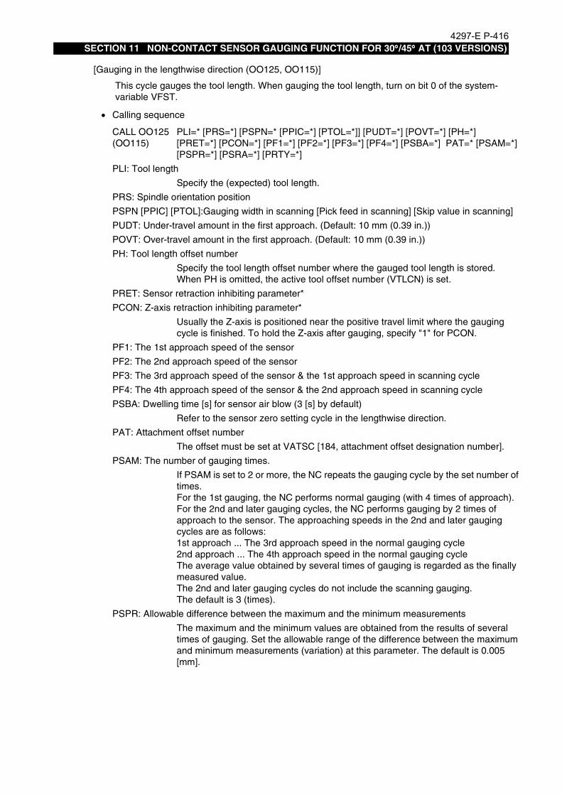
4297-E P-416SECTION 11 NON-CONTACT SENSOR GAUGING FUNCTION FOR 30°°°°/45°°°° AT (103 VERSIONS)
[Gauging in the lengthwise direction (OO125, OO115)]
• Calling sequence
This cycle gauges the tool length. When gauging the tool length, turn on bit 0 of the system-variable VFST.
CALL OO125(OO115)
PLI=* [PRS=*] [PSPN=* [PPIC=*] [PTOL=*]] [PUDT=*] [POVT=*] [PH=*][PRET=*] [PCON=*] [PF1=*] [PF2=*] [PF3=*] [PF4=*] [PSBA=*] PAT=* [PSAM=*][PSPR=*] [PSRA=*] [PRTY=*]
PLI: Tool length
Specify the (expected) tool length.
PRS: Spindle orientation position
PSPN [PPIC] [PTOL]:Gauging width in scanning [Pick feed in scanning] [Skip value in scanning]
PUDT: Under-travel amount in the first approach. (Default: 10 mm (0.39 in.))
POVT: Over-travel amount in the first approach. (Default: 10 mm (0.39 in.))
PH: Tool length offset number
Specify the tool length offset number where the gauged tool length is stored.When PH is omitted, the active tool offset number (VTLCN) is set.
PRET: Sensor retraction inhibiting parameter*
PCON: Z-axis retraction inhibiting parameter*
Usually the Z-axis is positioned near the positive travel limit where the gauging cycle is finished. To hold the Z-axis after gauging, specify "1" for PCON.
PF1: The 1st approach speed of the sensor
PF2: The 2nd approach speed of the sensor
PF3: The 3rd approach speed of the sensor & the 1st approach speed in scanning cycle
PF4: The 4th approach speed of the sensor & the 2nd approach speed in scanning cycle
PSBA: Dwelling time [s] for sensor air blow (3 [s] by default)
Refer to the sensor zero setting cycle in the lengthwise direction.
PAT: Attachment offset number
The offset must be set at VATSC [184, attachment offset designation number].
PSAM: The number of gauging times.
If PSAM is set to 2 or more, the NC repeats the gauging cycle by the set number oftimes.For the 1st gauging, the NC performs normal gauging (with 4 times of approach).For the 2nd and later gauging cycles, the NC performs gauging by 2 times of approach to the sensor. The approaching speeds in the 2nd and later gauging cycles are as follows:1st approach ... The 3rd approach speed in the normal gauging cycle2nd approach ... The 4th approach speed in the normal gauging cycleThe average value obtained by several times of gauging is regarded as the finally measured value.The 2nd and later gauging cycles do not include the scanning gauging.The default is 3 (times).
PSPR: Allowable difference between the maximum and the minimum measurements
The maximum and the minimum values are obtained from the results of several times of gauging. Set the allowable range of the difference between the maximumand minimum measurements (variation) at this parameter. The default is 0.005 [mm].

4297-E P-417SECTION 11 NON-CONTACT SENSOR GAUGING FUNCTION FOR 30°°°°/45°°°° AT (103 VERSIONS)
-
• Cycle operation
PSRA: Action to be taken when the variation exceeds the allowable range (alarm)
Set whether the variation exceeding the allowable range causes an alarm or not.Set "1" if you want an alarm to be generated. Set "0" if not. The default is "0" (no alarm).
PRTY: Action to be taken when the variation exceeds the allowable range (retry).
Set whether the variation exceeding the allowable range triggers another gauging cycle or not. When retry is desired, set the number of retry times at PRTY.If retry is not desired, set "0" at PRTY.The NC performs gauging by the number of times set at PSAM (number of gaugingtimes) for each retry gauging. During the retry gauging, two times of approach is made even in the 1st gauging cycle.If the variation does not fall within the allowable range after the specified number ofretrials, an alarm occurs.If PSRA is set to "1", the PRTY value is ignored. If "0" is set at both PSRA and PRTY, the average value is regarded as the measured value even when the variation is out of the allowable range. The default is "0" (no retry).
1. The sensor-air-blower is turned off.
2. The sensor is positioned near the Z-axis positive limit.
3. The sensor is positioned at the Y-axis retract position, if the machine needs retraction of Y-axis before gauging.
4. Spindle orientation is done except for gauging of rotating tool.
5. The sensor advances.
6. The Y-axis is positioned on the extension line from the sensor position in the tool length-wise direction.
7. The X-axis is positioned at the gauging start position.
8. Gauging cycle starts. (Sensor air blow is carried out for the 1st gauging.)
9. The Y-axis and the Z-axis move to the sensor position.
10. Scanning cycle starts if the cycle is selected.
11. In the case of several times of gauging, the NC repeats the gauging cycle by the specified number of times.
12. The Z-axis moves to the sensor position.
13. The laser shutter closes.
14. The Y-axis retracts if it is so designed.*
15. The sensor retracts.*
* Positioning to the positive limit by the sequence No.12 is omitted when PCON is specified.Sensor retraction by the sequence No.14 and 15 is omitted when PRET is specified.

4297-E P-418SECTION 11 NON-CONTACT SENSOR GAUGING FUNCTION FOR 30°°°°/45°°°° AT (103 VERSIONS)
[Gauging in the radial direction (OO126, OO116)]
• Calling sequence
This cycle gauges the cutter radius. When gauging the cutter radius, turn on bit 0 of the sys-tem-variable VFST.
CALL OO126(OO116)
PRI=* PLI=* [PRS=*] [PSPN=* [PPIC=*] [PTOL=*]] [PIN=*] [PUDT=*] [POVT=*]PAT=* [PD=*] [PRET=*] [PCON=*] [PGO=*] [PF1=*] [PF2=*] [PF3=*] [PF4=*][PSBA=*] [PSAM=*] [PSPR=*] [PSRA=*] [PRTY=*]
PLI: Tool length
Specify the offset amount of the tool length.
PRI: Cutter radius
Specify the offset amount of the cutter radius (: the expected offset amount of the cutter radius).
PRS: Spindle orientation position
Refer to the sensor zero setting cycle in the lengthwise direction.
PSPN [PPIC] [PTOL]: Gauging width in scanning [Pick feed in scanning] [Skip value in scanning]
PIN: Z-axis infeed amount
Set a distance by which the Z-axis further advances from the original advanced distance in the sensor zero setting cycle in the radial direction.
PUDT: Under-travel amount in the first approach. (Default: 10 mm (0.39 in.))
POVT: Over-travel amount in the first approach. (Default: 10 mm (0.39 in.))
PAT: Attachment offset number
Refer to the [Gauging cycle in the lengthwise direction].
PD: Cutter radius compensation number
Specify the cutter radius compensation number where is stored the gauged cutterradius.When omitted, the active tool compensation number (VTLCN) is set.
PRET: Sensor retraction inhibiting parameter*
PCON: Z-axis retraction inhibiting parameter*
Usually the Z-axis is positioned near the positive travel limit where the gauging cycle is finished. To hold the Z-axis after gauging, specify "1" for PCON.
PF1: The 1st approach speed of the sensor
PF2: The 2nd approach speed of the sensor
PF3: The 3rd approach speed of the sensor & the 1st approach speed in scanning cycle
PF4: The 4th approach speed of the sensor & the 2nd approach speed in scanning cycle
PSBA: Dwelling time [s] for sensor air blow (3 [s] by default)
PSAM: The number of gauging times
PSPR: Allowable difference between the maximum and the minimum measurements
PSRA: Action to be taken when the variation exceeds the allowable range (alarm)
PRTY: Action to be taken when the variation exceeds the allowable range (retry)
Refer to the sensor zero setting cycle in the lengthwise direction and the gauging cycle in the lengthwise direction.

4297-E P-419SECTION 11 NON-CONTACT SENSOR GAUGING FUNCTION FOR 30°°°°/45°°°° AT (103 VERSIONS)
• Cycle operation
1. The laser shutter opens.
2. The sensor is positioned near the Z-axis positive limit.
3. The sensor is positioned at the Y-axis retract position, if the machine needs retraction of Y-axis before gauging.
4. Spindle orientation is done except for gauging of rotating tool.
5. The sensor advances.
6. Position the Y-axis at the under-travel position (if PIN is designated, locate the Y-axis in a position shifted by the Y-axis component of PIN).
7. The X-axis is positioned at the gauging start position.
8. Position the Z-axis at the under-travel position (if PIN is designated, locate the Z-axis in a position shifted by the Z-axis component of PIN).
9. Gauging cycle starts. (Sensor air blow is carried out for the 1st gauging.)
10. The Y-axis and the Z-axis move to the sensor position.
11. Scanning cycle starts if the cycle is selected.
12. In the case of several times of gauging, the NC repeats the gauging cycle by the specified number of times.
13. The sensor is positioned near the Z-axis positive limit.*
14. The laser shutter closes.
15. The Y-axis retracts if it is so designed.*
16. The sensor retracts.*
* Positioning to the positive limit by the sequence No.13 is omitted when PCON is specified.Sensor retraction by the sequence No.15 and 16 is omitted when PRET is specified.
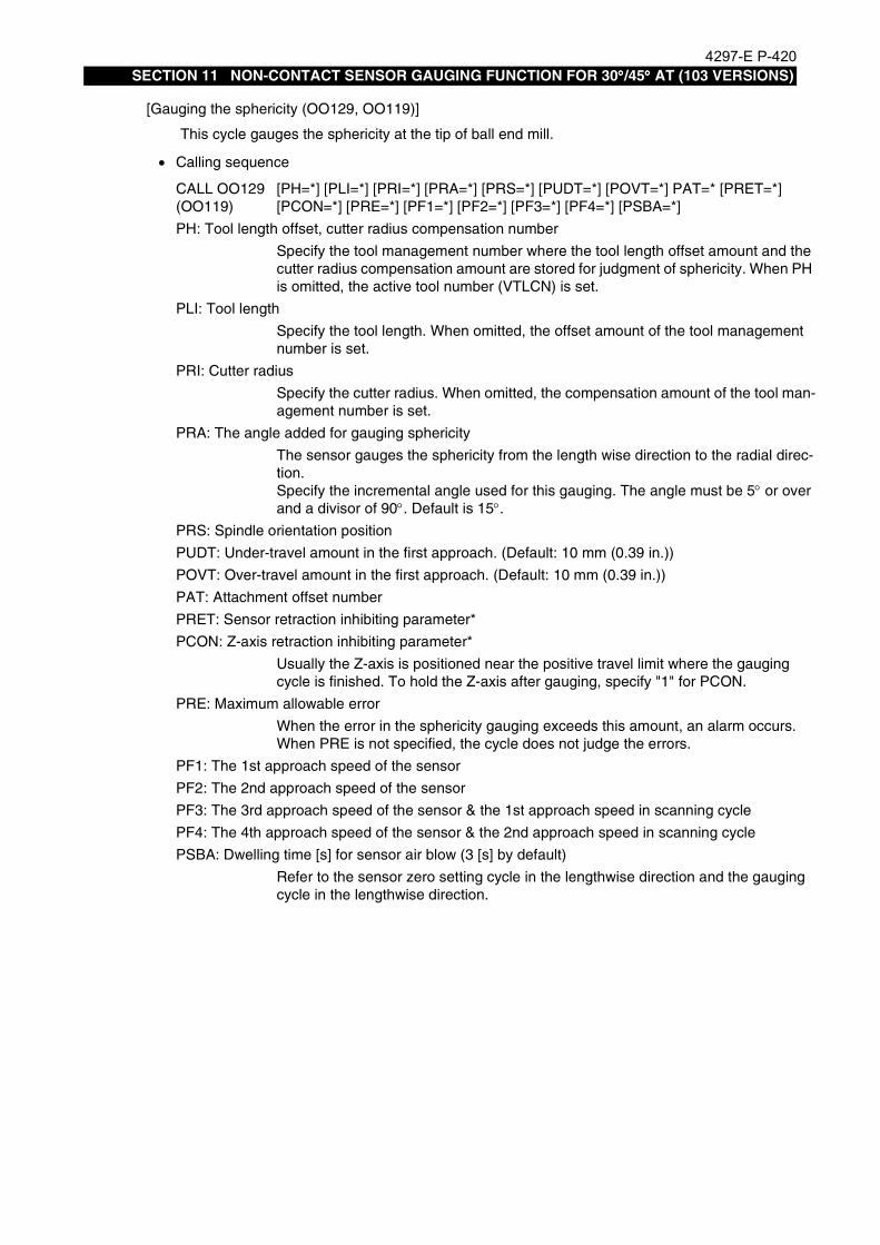
4297-E P-420SECTION 11 NON-CONTACT SENSOR GAUGING FUNCTION FOR 30°°°°/45°°°° AT (103 VERSIONS)
-
[Gauging the sphericity (OO129, OO119)]
• Calling sequence
This cycle gauges the sphericity at the tip of ball end mill.
CALL OO129(OO119)
[PH=*] [PLI=*] [PRI=*] [PRA=*] [PRS=*] [PUDT=*] [POVT=*] PAT=* [PRET=*][PCON=*] [PRE=*] [PF1=*] [PF2=*] [PF3=*] [PF4=*] [PSBA=*]
PH: Tool length offset, cutter radius compensation number
Specify the tool management number where the tool length offset amount and thecutter radius compensation amount are stored for judgment of sphericity. When PHis omitted, the active tool number (VTLCN) is set.
PLI: Tool length
Specify the tool length. When omitted, the offset amount of the tool management number is set.
PRI: Cutter radius
Specify the cutter radius. When omitted, the compensation amount of the tool management number is set.
PRA: The angle added for gauging sphericity
The sensor gauges the sphericity from the length wise direction to the radial direc-tion.Specify the incremental angle used for this gauging. The angle must be 5° or overand a divisor of 90°. Default is 15°.
PRS: Spindle orientation position
PUDT: Under-travel amount in the first approach. (Default: 10 mm (0.39 in.))
POVT: Over-travel amount in the first approach. (Default: 10 mm (0.39 in.))
PAT: Attachment offset number
PRET: Sensor retraction inhibiting parameter*
PCON: Z-axis retraction inhibiting parameter*
Usually the Z-axis is positioned near the positive travel limit where the gauging cycle is finished. To hold the Z-axis after gauging, specify "1" for PCON.
PRE: Maximum allowable error
When the error in the sphericity gauging exceeds this amount, an alarm occurs.When PRE is not specified, the cycle does not judge the errors.
PF1: The 1st approach speed of the sensor
PF2: The 2nd approach speed of the sensor
PF3: The 3rd approach speed of the sensor & the 1st approach speed in scanning cycle
PF4: The 4th approach speed of the sensor & the 2nd approach speed in scanning cycle
PSBA: Dwelling time [s] for sensor air blow (3 [s] by default)
Refer to the sensor zero setting cycle in the lengthwise direction and the gauging cycle in the lengthwise direction.

4297-E P-421SECTION 11 NON-CONTACT SENSOR GAUGING FUNCTION FOR 30°°°°/45°°°° AT (103 VERSIONS)
• Cycle operation
1. The laser shutter opens.
2. The sensor is positioned near the Z-axis positive limit.
3. The sensor is positioned at the Y-axis retract position, if the machine needs retraction of Y-axis before gauging.
4. Spindle orientation is done except for gauging of rotating tool.
5. The sensor advances.
6. The Y-axis is positioned on the extension line from the sensor position in the tool length-wise direction.
7. The X-axis is positioned at the gauging start position.
8. Gauging cycle starts.(Sensor air blow is carried out for the 1st gauging.)
9. The Y-axis and the Z-axis move to the sensor position.
10. The PRA angle is added and the sensor gauges sphericity in the slanting direction.
11. Operation sequences No.9 and 10 are repeated up to the gauging angle of 90°.12. The X-axis and Z-axis move to the sensor position.
13. The laser shutter closes.
14. The Y-axis retracts if it is so designed.*
15. The sensor retracts.*
16. The sphericity is judged, if the judgement command is specified.
* Positioning to the positive limit by the sequence No.12 is omitted when PCON is specified.Sensor retraction by the sequence No.14 and 15 is omitted when PRET is specified.

4297-E P-422SECTION 11 NON-CONTACT SENSOR GAUGING FUNCTION FOR 30°°°°/45°°°° AT (103 VERSIONS)
[Tool breakage detection in the lengthwise direction (OO125, OO115)]
• Calling sequence
This cycle detect the tool breakage in the lengthwise direction. When the breakage detection in the lengthwise direction, turnoff bit 0 of the system-variable VFST.
CALL OO125(OO115)
[PLI=*][PRS=*] [PSPN=* [PPIC=*] [PTOL=*]] [PUDT=*] [POVT=*] [PAT=*] [PH=*][PRET=*] [PCON=*] [PGO=*] [PLE1=*] [PLE2=*][PF1=*] [PF2=*] [PF3=*] [PF4=*][PSBA=*] [PSAM=*] [PSPR=*] [PSRA=*] [PRTY=*]
PLI: Tool length
Specify the tool length (: the expected tool length).
PRS: Spindle orientation position
PSPN [PPIC] [PTOL]: Gauging width in scanning[Pick feed in scanning] [Skip value in scanning]
PUDT: Under-travel amount in the first approach. (Default: 10 mm (0.39 in.))
POVT: Over-travel amount in the first approach. (Default: 10 mm (0.39 in.))
PAT: Attachment offset number
PH: Tool length offset number
Specify the tool length offset number of which data is compared with the gauging result.When omitted, the active tool number (VTLCN) is set.
PRET: Sensor retraction inhibiting parameter*
PCON: Z-axis retraction inhibiting parameter*
Usually the Z-axis is positioned near the positive travel limit where the gauging cycle is finished. To hold the Z-axis after gauging, specify "1" for PCON.
PGO: Action to be taken on detection of tool breakage
PGO=1 The tool is changed on detection of tool breakage.
PGO=2 The tool is changed on detection of tool breakage. The broken tool movesto the tool change position before being changed.
If PGO is omitted, the cycle ends with alarm occurrence.
PLE1: Threshold value for judging tool breakage
Specify the threshold value for judging tool breakage as a difference from the tool offset value. Default is 0.1 mm (0.004 in.).
PLE2: Threshold value for judging tool wear
Specify the threshold value for judging tool wear as a difference from the tool offsetvalue. When the difference is less than PLE2, the NC judges that the tool is worn and up dates the tool length offset amount. If PLE2 is omitted, the NC does not make this judgment.
PF1: The 1st approach speed of the sensor
PF2: The 2nd approach speed of the sensor
PF3: The 3rd approach speed of the sensor & the 1st approach speed in scanning cycle
PF4: The 4th approach speed of the sensor & the 2nd approach speed in scanning cycle
PSBA: Dwelling time [s] for sensor air blow (3 [s] by default)
PSAM: The number of gauging times
PSPR: Allowable difference between the maximum and the minimum measurements
PSRA: Action to be taken when the variation exceeds the allowable range (alarm)
PRTY: Action to be taken when the variation exceeds the allowable range (retry)
Refer to the sensor zero setting cycle in the lengthwise direction and the gauging cycle in the lengthwise direction.

4297-E P-423SECTION 11 NON-CONTACT SENSOR GAUGING FUNCTION FOR 30°°°°/45°°°° AT (103 VERSIONS)
• Cycle operation
1. The laser shutter opens.
2. The sensor is positioned near the Z-axis positive limit.
3. The sensor is positioned at the Y-axis retract position, if the machine needs retraction of Y-axis before gauging.
4. Spindle orientation is done except for gauging of rotating tool.
5. The sensor advances.
6. The Y-axis is positioned on the extension line from the sensor position in the tool length-wise direction.
7. The X-axis is positioned at the sensor position.
8. Gauging cycle starts. (Sensor air blow is carried out for the 1st gauging.)
9. The Y-axis and the Z-axis move to the sensor position.
10. Scanning cycle starts if the cycle is selected.
11. In the case of several times of gauging, the NC repeats the gauging cycle by the specified number of times.
12. The sensor is positioned near the Z-axis positive limit.*
13. The laser shutter closes.
14. The Y-axis retracts if it is so designed.*
15. The sensor retracts.*
16. The tool breakage or the tool wear are judged.
17. When the tool breakage is detected, the tool is changed according to the PGO setting.
* Positioning to the positive limit by the sequence No.12 is omitted when PCON is specified.Sensor retraction by the sequence No.14 and 15 is omitted when PRET is specified.
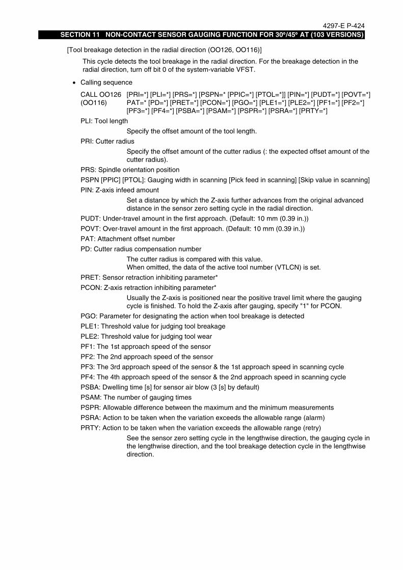
4297-E P-424SECTION 11 NON-CONTACT SENSOR GAUGING FUNCTION FOR 30°°°°/45°°°° AT (103 VERSIONS)
[Tool breakage detection in the radial direction (OO126, OO116)]
• Calling sequence
This cycle detects the tool breakage in the radial direction. For the breakage detection in the radial direction, turn off bit 0 of the system-variable VFST.
CALL OO126(OO116)
[PRI=*] [PLI=*] [PRS=*] [PSPN=* [PPIC=*] [PTOL=*]] [PIN=*] [PUDT=*] [POVT=*]PAT=* [PD=*] [PRET=*] [PCON=*] [PGO=*] [PLE1=*] [PLE2=*] [PF1=*] [PF2=*][PF3=*] [PF4=*] [PSBA=*] [PSAM=*] [PSPR=*] [PSRA=*] [PRTY=*]
PLI: Tool length
Specify the offset amount of the tool length.
PRI: Cutter radius
Specify the offset amount of the cutter radius (: the expected offset amount of the cutter radius).
PRS: Spindle orientation position
PSPN [PPIC] [PTOL]: Gauging width in scanning [Pick feed in scanning] [Skip value in scanning]
PIN: Z-axis infeed amount
Set a distance by which the Z-axis further advances from the original advanced distance in the sensor zero setting cycle in the radial direction.
PUDT: Under-travel amount in the first approach. (Default: 10 mm (0.39 in.))
POVT: Over-travel amount in the first approach. (Default: 10 mm (0.39 in.))
PAT: Attachment offset number
PD: Cutter radius compensation number
The cutter radius is compared with this value.When omitted, the data of the active tool number (VTLCN) is set.
PRET: Sensor retraction inhibiting parameter*
PCON: Z-axis retraction inhibiting parameter*
Usually the Z-axis is positioned near the positive travel limit where the gauging cycle is finished. To hold the Z-axis after gauging, specify "1" for PCON.
PGO: Parameter for designating the action when tool breakage is detected
PLE1: Threshold value for judging tool breakage
PLE2: Threshold value for judging tool wear
PF1: The 1st approach speed of the sensor
PF2: The 2nd approach speed of the sensor
PF3: The 3rd approach speed of the sensor & the 1st approach speed in scanning cycle
PF4: The 4th approach speed of the sensor & the 2nd approach speed in scanning cycle
PSBA: Dwelling time [s] for sensor air blow (3 [s] by default)
PSAM: The number of gauging times
PSPR: Allowable difference between the maximum and the minimum measurements
PSRA: Action to be taken when the variation exceeds the allowable range (alarm)
PRTY: Action to be taken when the variation exceeds the allowable range (retry)
See the sensor zero setting cycle in the lengthwise direction, the gauging cycle in the lengthwise direction, and the tool breakage detection cycle in the lengthwise direction.

4297-E P-425SECTION 11 NON-CONTACT SENSOR GAUGING FUNCTION FOR 30°°°°/45°°°° AT (103 VERSIONS)
• Cycle operation
1. The laser shutter opens.
2. The sensor is positioned near the Z-axis positive limit.
3. The sensor is positioned at the Y-axis retract position, if the machine needs retraction of Y-axis before gauging.
4. Spindle orientation is done except for gauging of rotating tool.
5. The sensor advances.
6. Position the Y-axis at the under-travel position (if PIN is designated, locate the Y-axis in a position shifted by the Y-axis component of PIN).
7. The X-axis is positioned at the gauging start position.
8. Position the Z-axis at the under-travel position (if PIN is designated, locate the Z-axis in a position shifted by the Z-axis component of PIN).
9. Gauging cycle starts. (Sensor air blow is carried out for the 1st gauging.)
10. The Y-axis and the Z-axis move to the sensor position.
11. Scanning cycle starts if the cycle is selected.
12. In the case of several times of gauging, the NC repeats the gauging cycle by the specified number of times.
13. The sensor is positioned near the Z-axis positive limit.*
14. The laser shutter closes.
15. The Y-axis retracts if it is so designed.*
16. The sensor retracts.*
17. The tool breakage or the tool wear are judged.
18. When the tool breakage is detected, the tool is changed according to the PGO setting.
* Positioning to the positive limit by the sequence No.13 is omitted when PCON is specified.Sensor retraction by the sequence No.15 and 16 is omitted when PRET is specified.

4297-E P-426SECTION 11 NON-CONTACT SENSOR GAUGING FUNCTION FOR 30°°°°/45°°°° AT (103 VERSIONS)
-
[High-speed tool breakage detection (OO127, OO117)]
EIOEMR5SA005R01
• Calling sequence
This cycle measure the tool length to detect broken tool at high speed. The high-speed tool breakage detection is executed on the assumption that a broken tool does not interrupt the sensor beam as shown in the right figure.This cycle, however, may not be able to detects light tool breakage.
CALL OO127(OO117)
[PLI=*] [PRI=*] [PRS=*] [PIN=*] [PUDT=*] [POVT=*] PAT=* [PH=*] [PRET=*][PCON=*]
PLI: Tool length
Specify the tool length offset amount. When omitted, the value specified with the offset number is set.
PRI: Cutter radius
Specify the cutter radius compensation amount. When omitted, the value specifiedwith the offset number is set.
PRS: Spindle orientation position
PIN: Z-axis infeed amount
The sensor starts gauging by shifting from the starting position in the negative direction by a distance specified with PIN. (Default: 0.2 mm (0.008 in.))
PUDT: Under-travel amount in the first approach. (Default: 50 mm (1.97 in.))
POVT: Over-travel amount in the first approach. (Default: 10 mm (0.39 in.))
PAT: Attachment offset number
PH: Tool offset number
Specify the tool off set number. When omitted, the active tool number (VTLCN) is set.
PRET: Sensor retraction inhibiting parameter*
PCON: Z-axis retraction inhibiting parameter*
Usually the Z-axis is positioned near the positive travel limit where the gauging cycle is finished. To hold the Z-axis after gauging, specify "1" for PCON.Refer to the sensor zero setting cycle in the lengthwise direction and the gauging cycle in the lengthwise direction.

4297-E P-427SECTION 11 NON-CONTACT SENSOR GAUGING FUNCTION FOR 30°°°°/45°°°° AT (103 VERSIONS)
• Cycle operation
1. The laser shutter opens.
2. The sensor is positioned near the Z-axis positive limit.
3. The sensor is positioned at the Y-axis retract position, if the machine needs retraction of Y-axis before gauging.
4. Spindle orientation is done except for gauging of rotating tool.
5. The sensor advances.
6. Position the Y-axis at the under-travel position (if PIN is designated, locate the Y-axis in a position shifted by the Y-axis component of PIN).
7. The X-axis is positioned at the gauging start position.
8. Position the Z-axis at the under-travel position (if PIN is designated, locate the Z-axis in a position shifted by the Z-axis component of PIN).
9. The Y-axis and the Z-axis skip to the target position (sensor position + over travel posi-tion).
10. The sensor is positioned near the Z-axis positive limit.*
11. The laser shutter closes.
12. The Y-axis retracts if it is so designed.*
13. The sensor retracts.*
14. The tool breakage is judged.
15. When the tool breakage is detected, the tool is changed according to the PGO setting.
* Positioning to the positive limit by the sequence No.10 is omitted when PCON is specified.Sensor retraction by the sequence No.12 and 13 is omitted when PRET is specified.

4297-E P-428SECTION 11 NON-CONTACT SENSOR GAUGING FUNCTION FOR 30°°°°/45°°°° AT (103 VERSIONS)
5. List of AlarmsEeoemr5sa0052583 Alarm B UNTENDED: Large error in measurement of sphericity
Large errors were detected in measurement of sphericity.[Probable Faulty Locations]In the sensor zero setting cycle, the sensor zero position in the horizontal direction did not match the tool center.Or, the measuring tool was defective.
[Measures to Take]Use a proper tool, such as a spare tool.
2305 Alarm B UNTENDED: Measurement impossible
Measurement became impossible during auto gauging cycle.For this gauging system, the following codes are added to this alarm:
6A Sensor 4 could not be confirmed in the first approach.
6B Contact could not be confirmed in the first approach.
6C Sensor 4 could not be confirmed in the second approach.
6D Contact could not be confirmed in the second approach.
6E Sensor 4 could not be confirmed in the third approach.
6F Contact could not be confirmed in the third approach.
70 Sensor 4 could not be confirmed in the fourth approach.
71 Contact could not be confirmed in the fourth approach.
72 Sensor 4 could not be confirmed in retraction of the skipping cycle.
73 Contact could not be confirmed in the first approach of the skipping cycle.
74 Sensor 4 could not be confirmed in retraction of the skipping cycle.
75 Contact could not be confirmed in the second approach of the skipping cycle.
7B The first sensor could not be confirmed in the high-speed tool breakage detection cycle.
7C The sensor could not be confirmed after skipping in the high-speed tool breakage detection cycle.
95 In the plural measurement operations, the difference between the minimum and maximum measured values exceeded the tolerance.
96 The attachment type does not match the gauging program number.30° angular AT OO125, OO126, OO127, and OO129 are usable.45° angular AT OO115, OO116, OO117, and OO119 are usable.Vertical/Horizontal spindles
In execution of OO95, OO96, OO97, or OO99, no attachment is mounted, or the attachment is not extension one, 90° angular one, or B-/C-axis one.
97 The attachment is not indexed to an angle where measurement is possible.30° angular AT Not indexed to C270°45° angular AT Not indexed to C270°Vertical/Horizontal spindles 90° angular AT not indexed to C270°
B-/C-axis AT indexed to B90° but not indexed to C270°99 The vertical/horizontal spindle tool command (bit 6 of VFST) is wrong.
"1" (horizontal spindle) is set at bit 6 of VFST when no attachment was mounted or an extension AT was mounted for vertical/horizontal spindle measurement. Or, "0" (horizontal spindle) is set at bit 6 of VFST when 90° angular AT or B-/C-axis AT is mounted.

LIST OF PUBLICATIONS
Publication No. Date Edition
4297-E January 2000 2nd
4297-E-R1 October 2000 3rd
4297-E-R2 February 2001 4th
4297-E-R3 September 2002 5th
4297-E-R4 December 2002 6th
4297-E-R5 July 2004 7th
4297-E-R6 August 2004 8th
This manual may be at variance with the actual product due to specification or design changes.Please also note that pecifications are subject to change without notice.If you requireclarification or further explanation of any point in this manual, please contact your OKUMA representative.