Embed Size (px)
Citation preview
Paavai Institutions Department of MECH
UNIT-V 5. 1
ME1251 THERMAL ENGINEERING
UNIT V
REFRIGERATION AND AIR CONDITIONING
www.vidyarthiplus.com
Paavai Institutions Department of MECH
UNIT-V 5. 2
CONTENTS
TECHNICAL TERMS
5.1 Fundamentals of refrigeration
5.2 Common Refrigerants
5.3 Required Properties of Ideal Refrigerant
5.4 Coefficient of Performance (COP)
5.5 Vapour Compression Refrigeration
5.5.1 Schematic of a Basic Vapor Compression Refrigeration System
5.5.2 Alternative Refrigerants for Vapour Compression Systems
5.6 Vapour Absorption Refrigeration
5.7 Comparison between Vapor Compression and Absorption System
5.8 Ton of refrigeration
5.9 Air- Conditioning System
5.9.1. Zoned Systems
5.9.2 Unitary Systems
5.10 Window Air-conditioning System
5.10.1 Blower
5.10.2 Propeller fan or the condenser fan
5.11.3 Fan motor
5.11 Split Air-conditioning System
5.11.1 Evaporator Coil or the Cooling Coil
5.11.2 Air Filter
5.11.3 Cooling Fan or Blower
5.11.4 Drain Pipe
5.11.5 Louvers or Fins
5.12 Solved Problems
5.13 Two Marks University Questions
5.14 University Essay Questions
www.vidyarthiplus.com
Paavai Institutions Department of MECH
UNIT-V 5. 3
TECHNICAL TERMS
1. SPECIFIC HEAT
It is the ratio between the quantities of heat required to change the temperature of 1
pound of any substance 1°F, as compared to the quantity of heat required to change 1 pound of
water 1°F. Specific heat is equal to the number of Btu required to raise the temperature of 1
pound of a substance 1°F. For example, the specific heat of milk is .92, which means that 92 Btu
will be needed to raise 100 pounds of milk 1° F. The specific heat of water is 1, by adoption as a
standard, and specific heat of another substance (solid, liquid, or gas) is determined
experimentally by comparing it to water. Specific heat also expresses the heat-holding capacity
of a substance compared to that of water.
2. SENSIBLE HEAT
Heat that is added to, or subtracted from, a substance that changes its temperature but not
its physical state is called sensible heat. It is the heat that can be indicated on a thermometer.
This is the heat human senses also can react to, at least within certain ranges. For example, if a
person put their finger into a cup of water, the senses readily tell that person whether it is cold,
cool, tepid, hot, or very hot. Sensible heat is applied to a solid, a liquid, or a gas/vapor as
indicated on a thermometer. The term sensible heat does not apply to the process of conversion
from one physical state to another.
3. LATENT HEAT
It is the term used for the heat absorbed or given off by a substance while it is changing
its physical state. When this occurs, the heat given off or absorbed does NOT cause a
temperature change in the substance. In other words, sensible heat is the term for heat that affects
the temperature of things; latent heat is the term for heat that affects the physical state of things.
To understand the concept of latent heat, you must realize that many substances may exist as
solids, as liquids, or as gases, depending primarily upon the temperatures and pressure to which
they are subjected.
4. SUPERHEAT
It is a very important term in the terminology of refrigeration - but it is unfortunately used
in different ways. It can be used to describe a process where refrigerant vapour is heated from its
www.vidyarthiplus.com
Paavai Institutions Department of MECH
UNIT-V 5. 4
saturated condition to a condition at higher temperature. The term superheat can also be used to
describe - or quantify - the end condition of the before-mentioned process.
5. PRESSURE
It is defined as a force per unit area. It is usually measured in pounds per square inch
(psi). Pressure may be in one direction, several directions, or in all directions. The ice (solid)
exerts pressure downward. The water (fluid) exerts pressure on all wetted surfaces of the
container. Gases exert pressure on al I inside surfaces of their containers.
6. VAPORIZATION
It is the process of changing a liquid to vapor, either by evaporation or boiling. When a
glass is filled with water, as shown in figure 6-10, and exposed to the rays of the sun for a day or
two, you should note that the water level drops gradually. The loss of water is due to
evaporation. Evaporation, in this case, takes place only at the surface of the liquid. It is gradual,
but the evaporation of the water can be speeded up if additional heat is applied to it. In this case,
the boiling of the water takes place throughout the interior of the liquid. Thus the absorption of
heat by a liquid causes it to boil and evaporate.
7. CONDENSATION
It is the process of changing a vapor into a liquid. For example, in figure 6-12, a warm
atmosphere gives up heat to a cold glass of water, causing moisture to condense out of the air
and form on the outside surface of the glass. Thus the removal of heat from a vapor causes the
vapor to condense.
8. COP of REFRIGERATION
The COP of a refrigeration system is the ratio of net refrigeration effect to the work
required to produce the effect.
9. UNIT OF REFRIGERATION
The capacity of refrigeration is expressed in tonnes of refrigeration (TOR).
1 tones of refrigeration = 210 kJ/min (or) = 3.5 kJ/sec (kW)
A tone of refrigeration is defined as the quantity of heat to be removed in order to form one tone
of ice at 0oC in 24 hours.
10. REFRIGERATION EFFECT
www.vidyarthiplus.com
Paavai Institutions Department of MECH
UNIT-V 5. 5
The amount of heat extracted in a given time is known as refrigeration effect.
11. EFFECTS OF UNDER COOLING
It increases the refrigeration effect therefore the COP increases. The mass flow rate of the
refrigeration is less than that for the simple saturated cycle. The reduced mass flow rate reduces
the piston displacement per minute. Power per tones of refrigeration losses due to reduction in
mass flow rate. The increased efficiency may be offering some extent by the rise in the
condenser pressure. Work input almost remains same. The heat rejection capacity of the
condenser increases.
12. EFFECTS OF SUPER HEATING
Supper heating increases the net refrigeration effect, but super heating requires more
work input therefore super heating reduces the COP.
No moisture contents in the refrigerant therefore no corrosion in the machines part.
13. PROPERTIES OF IDEAL REFRIGERANT
It should have low boiling point and low freezing point.
It must have low specific heat and high latent heat.
It should have high thermal conductivity to reduce the heat transfer in evaporator and
condenser.
It should have low specific volume to reduce the size of the compressor.
It should be non-flammable, non-expensive, non-toxic and non-corrosive.
It should have high critical pressure and temperature to avoid large power requirements.
It should give high COP to reduce the running cost of the system.
It must be cheap and must be readily available
14. RSHF
www.vidyarthiplus.com
Paavai Institutions Department of MECH
UNIT-V 5. 6
Room sensible heat factor is defined as the ratio of room sensible heat load to the room
total heat load.
15. RELATIVE HUMIDITY
It is defined as the ratio of partial pressure of water vapour (pw) in a mixture to the
saturation pressure (ps) of pure water at the same temperature of mixture.
16. SPECIFIC HUMIDITY
It is defined as the ratio of the mass of water vapour (ms) in a given volume to the mass
of dry air in a given volume (ma).
17. DEGREE OF SATURATION
It is the ratio of the actual specific humidity and the saturated specific humidity at the
same temperature of the mixture.
18. DEW POINT TEMPERATURE
The temperature at which the vapour starts condensing is called dew point temperature.
It is also equal to the saturation temperature at the partial pressure of water vapour in the
mixture. The dew point temperature is an indication of specific humidity.
19. SENSIBLE HEAT AND LATENT HEAT
Sensible heat is the heat that changes the temperature of the substance when added to it or
when abstracted from it. Latent heat is the heat that does not affect the temperature but change
of state occurred by adding the heat or by abstracting the heat.
20. PSYCHOMETRIC PROCESSES
1. Sensible heating and sensible cooling, 2. Cooling and dehumidification, 3. Heating
and humidification, 4. Mixing of air streams, 5. Chemical dehumidification, 6. Adiabatic
evaporative cooling.
21. ADIABATIC MIXING
The process of mixing two or more stream of air without any heat transfer to the
surrounding is known as adiabatic mixing. It is happened in air conditioning system.
22. DRY BULB TEMPERATURE (DBT)
www.vidyarthiplus.com
Paavai Institutions Department of MECH
UNIT-V 5. 7
The temperature recorded by the thermometer with a dry bulb. The dry bulb
thermometer cannot affected by the moisture present in the air. It is the measure of sensible heat
of the air.
23. WET BULB TEMPERATURE (WBT)
It is the temperature recorded by a thermometer whose bulb is covered with cotton wick
(wet) saturated with water. The wet bulb temperature may be the measure of enthalpy of air.
WBT is the lowest temperature recorded by moistened bulb.
24. DEW POINT DEPRESSION
It is the difference between dry bulb temperature and dew point temperature of air vapour
mixture.
www.vidyarthiplus.com
Paavai Institutions Department of MECH
UNIT-V 5. 8
UNIT V
REFRIGERATION AND AIR CONDITIONING
5.1 Fundamentals of refrigeration
The first mechanical refrigerators for the production of ice appeared around the year 1860. In
1880 the first ammonia compressors and insulated cold stores were put into use in the USA.
Electricity began to play a part at the beginning of this century and mechanical refrigeration
plants became common in some fields: e.g. breweries, slaughter-houses, fishery, ice production,
for example. After the Second World War the development of small hermetic refrigeration
compressors evolved and refrigerators and freezers began to take their place in the home. Today,
these appliances are regarded as normal household necessities.
Refrigeration is the process of removing heat from an area or a substance and is usually done by
an artificial means of lowering the temperature, such as the use of ice or mechanical
refrigeration.
Mechanical Refrigeration is defined as a mechanical system or apparatus so designed and
constructed that, through its function, heat is transferred from one substance to another. Since
refrigeration deals entirely with the removal or transfer of heat, some knowledge of the nature
and effects of heat is necessary for a clear understanding of the subject.
5.2 Common Refrigerants
Today, there are three specific types of refrigerants used in refrigeration and air-conditioning
systems:
1. Chlorofluorocarbons or CFCs, such as R-11, R-12, and R-114
2. Hydro chlorofluorocarbons or HCFCs, such as R-22 or R-123
3. Hydro fluorocarbons or HFCs, such as R-134a. All these refrigerants are "halogenated,"
which means they contain chlorine, fluorine, bromine, astatine, or iodine.
www.vidyarthiplus.com
Paavai Institutions Department of MECH
UNIT-V 5. 9
Refrigerants, such as Dichlorodifluoromethane (R-12), Mono chloro difluoromethane (R-22),
and Refrigerant 502 (R-502), are called primary refrigerants because each one changes its state
upon the application or absorption of heat, and, in this act of change, absorbs and extracts heat
from the area or substance.
The primary refrigerant is so termed because it acts directly upon the area or substance, although
it may be enclosed within a system. For a primary refrigerant to cool, it must be placed in a
closed system in which it can be controlled by the pressure imposed upon it. The refrigerant can
then absorb at the temperature ranges desired. If a primary refrigerant were used without being
controlled, it would absorb heat from most perishables and freeze them solid.
Secondary Refrigerants are substances, such as air, water, or brine. Though hot refrigerants in
themselves, they have been cooled by the primary refrigeration system; they pass over and
around the areas and substances to be cooled; and they are returned with their heat load to the
primary refrigeration system. Secondary refrigerants pay off where the cooling effect must be
moved over a long distance and gastight lines cost too much.
Refrigerants are classified into groups. The National Refrigeration Safety Code catalogs all
refrigerants into three groups:
Group I – safest of the refrigerants, such as R-12, R-22, and R-502
Group II – toxic and somewhat flammable, such as R-40 (Methyl chloride) and R-764
(Sulfur dioxide)
Group III – flammable refrigerants, such as R-170 (Ethane) and R-290 (Propane).
R-12 Dichlorodifluoromethane (CC12 F2) Dichlorodifluoromethane, commonly referred to as R-
12, is colorless and odorless in concentrations of less than 20 percent by volume in air. In higher
concentrations, its odor resembles that of carbon tetrachloride. It is nontoxic, noncorrosive,
nonflammable, and has a boiling point of -21.7°F (-29°C) at atmospheric pressure.
5.3 Required Properties of Ideal Refrigerant
1) The refrigerant should have low boiling point and low freezing point.
www.vidyarthiplus.com
Paavai Institutions Department of MECH
UNIT-V 5. 10
2) It must have low specific heat and high latent heat. Because high specific heat decreases the
refrigerating effect per kg of refrigerant and high latent heat at low temperature increases the
refrigerating effect per kg of refrigerant.
3) The pressures required to be maintained in the evaporator and condenser should be low
enough to reduce the material cost and must be positive to avoid leakage of air into the system.
4) It must have high critical pressure and temperature to avoid large power requirements.
5) It should have low specific volume to reduce the size of the compressor.
6) It must have high thermal conductivity to reduce the area of heat transfer in evaporator and
condenser.
7) It should be non-flammable, non-explosive, non-toxic and non-corrosive.
8) It should not have any bad effects on the stored material or food, when any leak develops in
the system.
9) It must have high miscibility with lubricating oil and it should not have reacting properly with
lubricating oil in the temperature range of the system.
10) It should give high COP in the working temperature range. This is necessary to reduce the
running cost of the system.
5.4Coefficient of Performance (COP)
The performance of refrigerators and heat pumps is expressed in terms of coefficient of
performance (COP), defined as
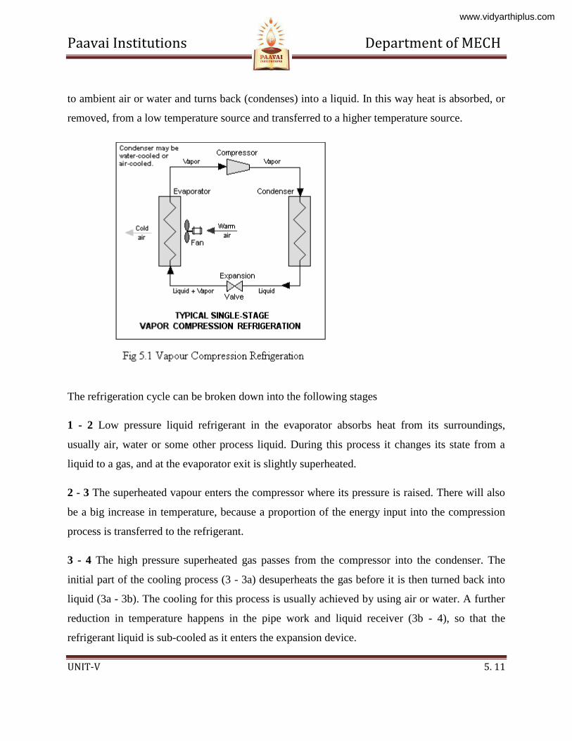
5.5 Vapour Compression Refrigeration
Heat flows naturally from a hot to a colder body. In refrigeration system the opposite
must occur i.e. heat flows from a cold to a hotter body. This is achieved by using a substance
called a refrigerant, which absorbs heat and hence boils or evaporates at a low pressure to form a
gas. This gas is then compressed to a higher pressure, such that it transfers the heat it has gained
www.vidyarthiplus.com
Paavai Institutions Department of MECH
UNIT-V 5. 11
to ambient air or water and turns back (condenses) into a liquid. In this way heat is absorbed, or
removed, from a low temperature source and transferred to a higher temperature source.
The refrigeration cycle can be broken down into the following stages
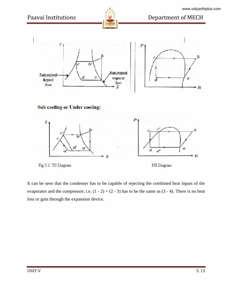
1 - 2 Low pressure liquid refrigerant in the evaporator absorbs heat from its surroundings,
usually air, water or some other process liquid. During this process it changes its state from a
liquid to a gas, and at the evaporator exit is slightly superheated.
2 - 3 The superheated vapour enters the compressor where its pressure is raised. There will also
be a big increase in temperature, because a proportion of the energy input into the compression
process is transferred to the refrigerant.
3 - 4 The high pressure superheated gas passes from the compressor into the condenser. The
initial part of the cooling process (3 - 3a) desuperheats the gas before it is then turned back into
liquid (3a - 3b). The cooling for this process is usually achieved by using air or water. A further
reduction in temperature happens in the pipe work and liquid receiver (3b - 4), so that the
refrigerant liquid is sub-cooled as it enters the expansion device.
www.vidyarthiplus.com
Paavai Institutions Department of MECH
UNIT-V 5. 12
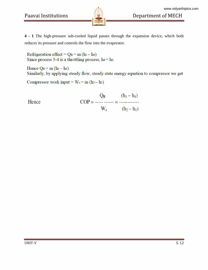
4 - 1 The high-pressure sub-cooled liquid passes through the expansion device, which both
reduces its pressure and controls the flow into the evaporator.
www.vidyarthiplus.com
Paavai Institutions Department of MECH
UNIT-V 5. 13
It can be seen that the condenser has to be capable of rejecting the combined heat inputs of the
evaporator and the compressor; i.e. (1 - 2) + (2 - 3) has to be the same as (3 - 4). There is no heat
loss or gain through the expansion device.
www.vidyarthiplus.com
Paavai Institutions Department of MECH
UNIT-V 5. 14
5.5.1 Schematic of a Basic Vapor Compression Refrigeration System
Advantages of Vapour compression refrigeration system over air refrigeration system:
• Since the working cycle approaches closer to carnot cycle, the C.O.P is quite high.
• Operational cost of vapour compression system is just above 1/4th of air refrigeration
www.vidyarthiplus.com
Paavai Institutions Department of MECH
UNIT-V 5. 15
system.
• Since the heat removed consists of the latent heat of vapour, the amount of liquid
circulated is less and as a result the size of the evaporator is smaller.
• Any desired temperature of the evaporator can be achieved just by adjusting the throttle
valve.
Disadvantages of Vapour compression refrigeration system over air refrigeration system
• Initial investment is high
• Prevention of leakage of refrigerant is a major problem
5.5.2 Alternative Refrigerants for Vapour Compression Systems
The use of CFCs is now beginning to be phased out due to their damaging impact on the
protective tropospheric ozone layer around the earth. The Montreal Protocol of 1987 and the
subsequent Copenhagen agreement of 1992 mandate a reduction in the production of ozone
depleting Chlorinated Fluorocarbon (CFC) refrigerants in a phased manner, with an eventual
stop to all production by the year 1996. In response, the refrigeration industry has developed two
alternative refrigerants; one based on Hydrochloro Fluorocarbon (HCFC), and another based on
Hydro Fluorocarbon (HFC). The HCFCs have a 2 to 10% ozone depleting potential as compared
to CFCs and also, they have an atmospheric lifetime between 2 to 25 years as compared to 100
or more years for CFCs (Brandt, 1992). However, even HCFCs are mandated to be phased out
by 2005, and only the chlorine free (zero ozone depletion) HFCs would be acceptable.
Until now, only one HFC based refrigerant, HFC 134a, has been developed. HCFCs are
comparatively simpler to produce and the three refrigerants 22, 123, and 124 have been
developed. The use of HFCs and HCFCs results in slightly lower efficiencies as compared to
CFCs, but this may change with increasing efforts being made to replace CFCs.
5.6 Vapour Absorption Refrigeration
www.vidyarthiplus.com
Paavai Institutions Department of MECH
UNIT-V 5. 16
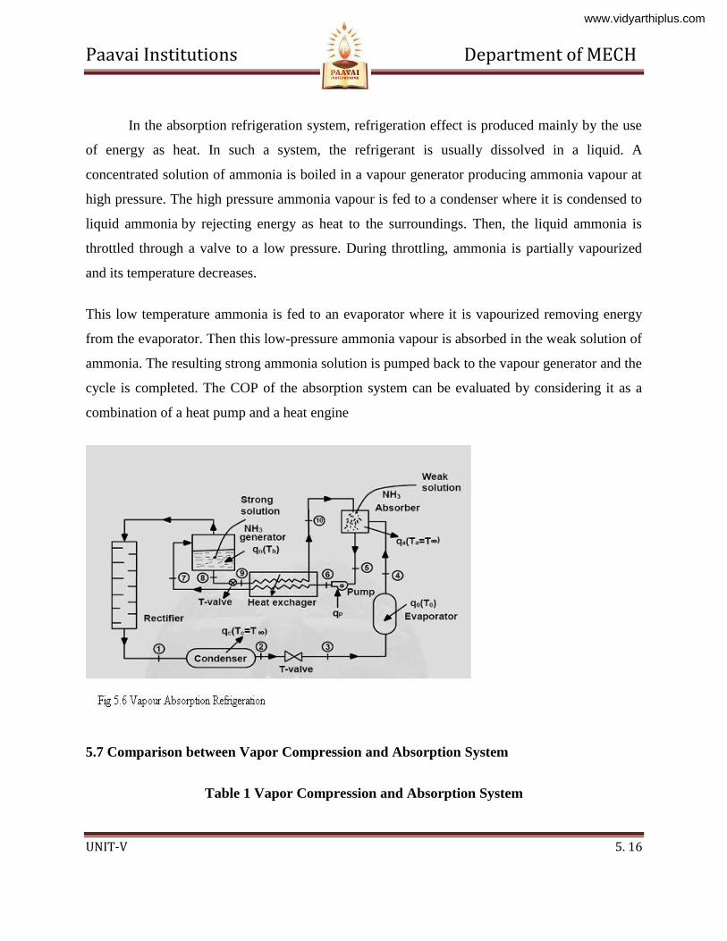
In the absorption refrigeration system, refrigeration effect is produced mainly by the use
of energy as heat. In such a system, the refrigerant is usually dissolved in a liquid. A
concentrated solution of ammonia is boiled in a vapour generator producing ammonia vapour at
high pressure. The high pressure ammonia vapour is fed to a condenser where it is condensed to
liquid ammonia by rejecting energy as heat to the surroundings. Then, the liquid ammonia is
throttled through a valve to a low pressure. During throttling, ammonia is partially vapourized
and its temperature decreases.
This low temperature ammonia is fed to an evaporator where it is vapourized removing energy
from the evaporator. Then this low-pressure ammonia vapour is absorbed in the weak solution of
ammonia. The resulting strong ammonia solution is pumped back to the vapour generator and the
cycle is completed. The COP of the absorption system can be evaluated by considering it as a
combination of a heat pump and a heat engine
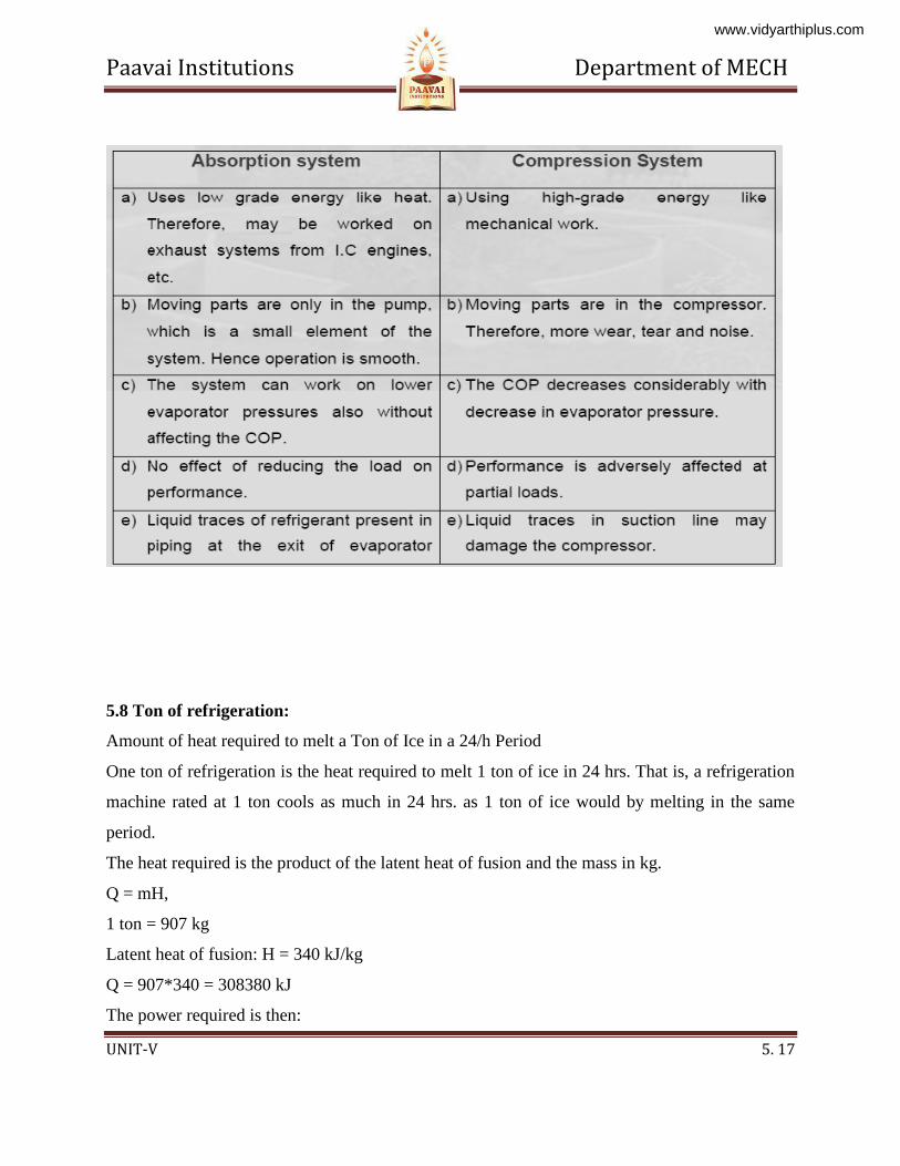
5.7 Comparison between Vapor Compression and Absorption System
Table 1 Vapor Compression and Absorption System
www.vidyarthiplus.com
Paavai Institutions Department of MECH
UNIT-V 5. 17
5.8 Ton of refrigeration:
Amount of heat required to melt a Ton of Ice in a 24/h Period
One ton of refrigeration is the heat required to melt 1 ton of ice in 24 hrs. That is, a refrigeration
machine rated at 1 ton cools as much in 24 hrs. as 1 ton of ice would by melting in the same
period.
The heat required is the product of the latent heat of fusion and the mass in kg.
Q = mH,
1 ton = 907 kg
Latent heat of fusion: H = 340 kJ/kg
Q = 907*340 = 308380 kJ
The power required is then:
www.vidyarthiplus.com
Paavai Institutions Department of MECH
UNIT-V 5. 18
P = E/t = Q/t = 308380 kJ/24 hr = 308380/(24*3600) = 3.57 kw
Note: 1 watt = 1 J/s
So that 1 kw = 1 kJ/s
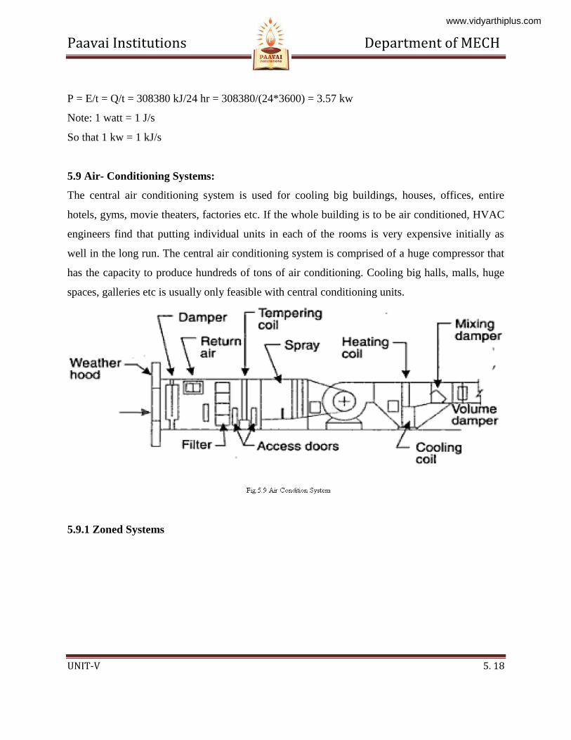
5.9 Air- Conditioning Systems:
The central air conditioning system is used for cooling big buildings, houses, offices, entire
hotels, gyms, movie theaters, factories etc. If the whole building is to be air conditioned, HVAC
engineers find that putting individual units in each of the rooms is very expensive initially as
well in the long run. The central air conditioning system is comprised of a huge compressor that
has the capacity to produce hundreds of tons of air conditioning. Cooling big halls, malls, huge
spaces, galleries etc is usually only feasible with central conditioning units.
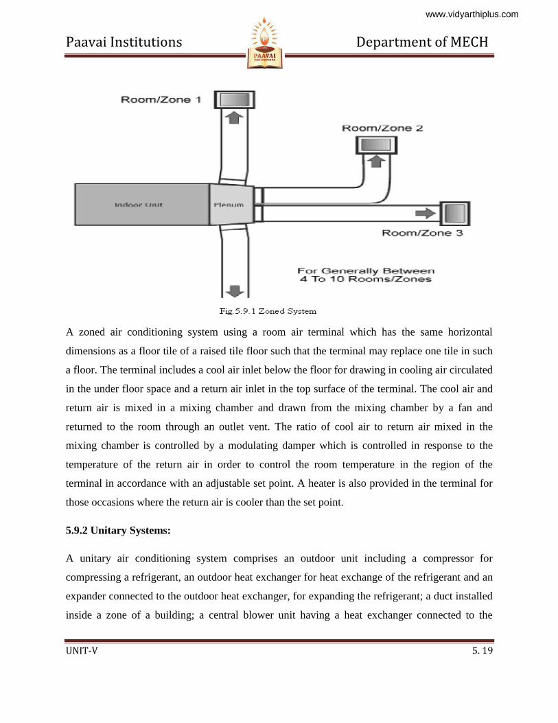
5.9.1 Zoned Systems
www.vidyarthiplus.com
Paavai Institutions Department of MECH
UNIT-V 5. 19
A zoned air conditioning system using a room air terminal which has the same horizontal
dimensions as a floor tile of a raised tile floor such that the terminal may replace one tile in such
a floor. The terminal includes a cool air inlet below the floor for drawing in cooling air circulated
in the under floor space and a return air inlet in the top surface of the terminal. The cool air and
return air is mixed in a mixing chamber and drawn from the mixing chamber by a fan and
returned to the room through an outlet vent. The ratio of cool air to return air mixed in the
mixing chamber is controlled by a modulating damper which is controlled in response to the
temperature of the return air in order to control the room temperature in the region of the
terminal in accordance with an adjustable set point. A heater is also provided in the terminal for
those occasions where the return air is cooler than the set point.
5.9.2 Unitary Systems:
A unitary air conditioning system comprises an outdoor unit including a compressor for
compressing a refrigerant, an outdoor heat exchanger for heat exchange of the refrigerant and an
expander connected to the outdoor heat exchanger, for expanding the refrigerant; a duct installed
inside a zone of a building; a central blower unit having a heat exchanger connected to the
www.vidyarthiplus.com
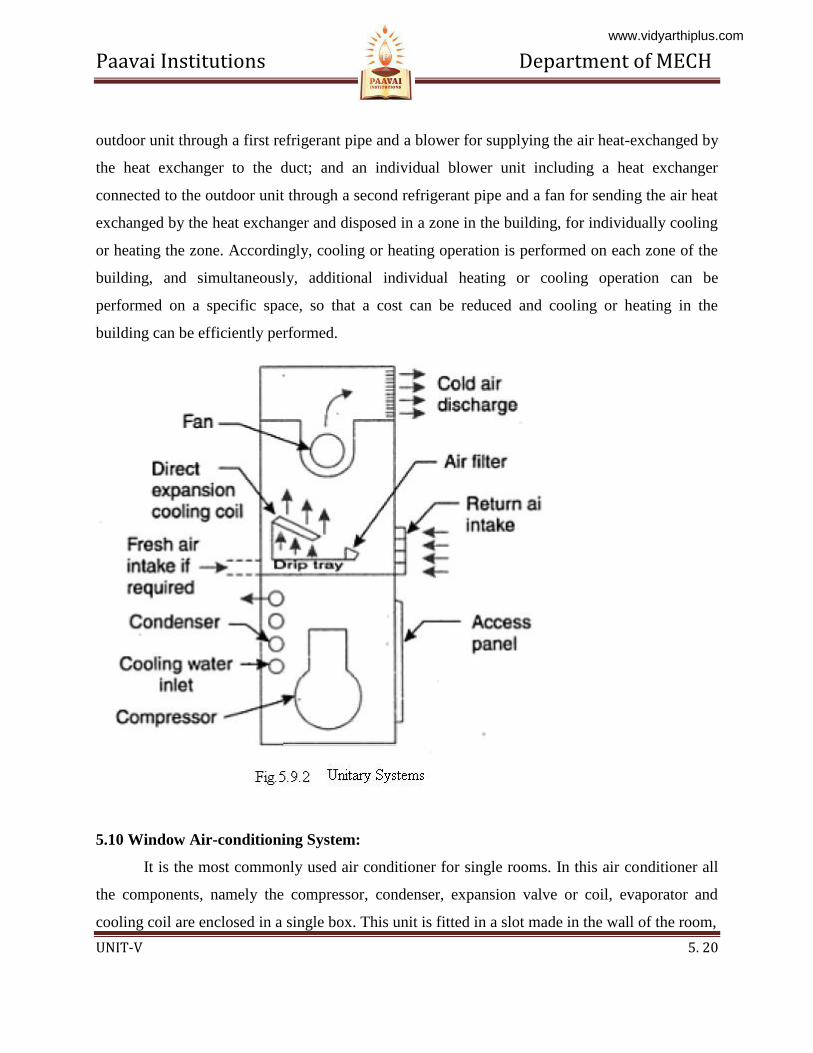
Paavai Institutions Department of MECH
UNIT-V 5. 20
outdoor unit through a first refrigerant pipe and a blower for supplying the air heat-exchanged by
the heat exchanger to the duct; and an individual blower unit including a heat exchanger
connected to the outdoor unit through a second refrigerant pipe and a fan for sending the air heat
exchanged by the heat exchanger and disposed in a zone in the building, for individually cooling
or heating the zone. Accordingly, cooling or heating operation is performed on each zone of the
building, and simultaneously, additional individual heating or cooling operation can be
performed on a specific space, so that a cost can be reduced and cooling or heating in the
building can be efficiently performed.
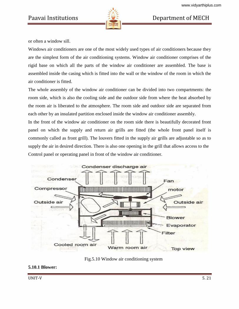
5.10 Window Air-conditioning System:
It is the most commonly used air conditioner for single rooms. In this air conditioner all
the components, namely the compressor, condenser, expansion valve or coil, evaporator and
cooling coil are enclosed in a single box. This unit is fitted in a slot made in the wall of the room,
www.vidyarthiplus.com
Paavai Institutions Department of MECH
UNIT-V 5. 21
or often a window sill.
Windows air conditioners are one of the most widely used types of air conditioners because they
are the simplest form of the air conditioning systems. Window air conditioner comprises of the
rigid base on which all the parts of the window air conditioner are assembled. The base is
assembled inside the casing which is fitted into the wall or the window of the room in which the
air conditioner is fitted.
The whole assembly of the window air conditioner can be divided into two compartments: the
room side, which is also the cooling side and the outdoor side from where the heat absorbed by
the room air is liberated to the atmosphere. The room side and outdoor side are separated from
each other by an insulated partition enclosed inside the window air conditioner assembly.
In the front of the window air conditioner on the room side there is beautifully decorated front
panel on which the supply and return air grills are fitted (the whole front panel itself is
commonly called as front grill). The louvers fitted in the supply air grills are adjustable so as to
supply the air in desired direction. There is also one opening in the grill that allows access to the
Control panel or operating panel in front of the window air conditioner.
Fig.5.10 Window air conditioning system
5.10.1 Blower:
www.vidyarthiplus.com
Paavai Institutions Department of MECH
UNIT-V 5. 22
This is the small blower that is fitted behind the evaporator or cooling coil inside the
assembly of the window air conditioner system. The blower sucks the air from the room which
first passes over the air filter and gets filtered. The air then passes over the cooling coil and gets
chilled. The blower then blows this filtered and chilled air, which passes through the supply air
compartment inside the window air conditioner assembly. This air is then delivered into the
room from the supply air grill of the front panel.
5.10.2 Propeller fan or the condenser fan:
The condenser fan is the forced draft type of propeller fan that sucks the atmospheric air
and blows it over the condenser. The hot refrigerant inside the condenser gives up the heat to the
atmospheric air and its temperature reduces.
5.10.3 Fan motor:
The motor inside the window air conditioner assembly is located between the condenser
and the evaporator coil. It has double shaft on one side of which the blower is fitted and on the
other side the condenser fan is fitted. This makes the whole assembly of the blower, the
condenser fan and the motor highly compact.
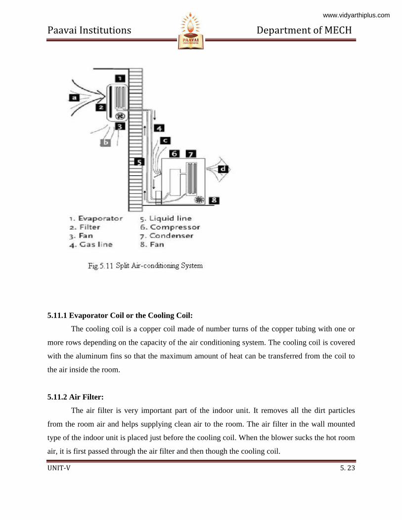
5.11 Split Air-conditioning System:
The split air conditioner comprises of two parts: the outdoor unit and the indoor unit. The
outdoor unit, fitted outside the room, houses components like the compressor, condenser and
expansion valve. The indoor unit comprises the evaporator or cooling coil and the cooling fan.
For this unit you don't have to make any slot in the wall of the room. Further, the present day
split units have aesthetic looks and add to the beauty of the room. The split air conditioner can be
used to cool one or two rooms.
www.vidyarthiplus.com
Paavai Institutions Department of MECH
UNIT-V 5. 23
5.11.1 Evaporator Coil or the Cooling Coil:
The cooling coil is a copper coil made of number turns of the copper tubing with one or
more rows depending on the capacity of the air conditioning system. The cooling coil is covered
with the aluminum fins so that the maximum amount of heat can be transferred from the coil to
the air inside the room.
5.11.2 Air Filter:
The air filter is very important part of the indoor unit. It removes all the dirt particles
from the room air and helps supplying clean air to the room. The air filter in the wall mounted
type of the indoor unit is placed just before the cooling coil. When the blower sucks the hot room
air, it is first passed through the air filter and then though the cooling coil.
www.vidyarthiplus.com
Paavai Institutions Department of MECH
UNIT-V 5. 24
5.11.3 Cooling Fan or Blower:
Inside the indoor unit there is also a long blower that sucks the room air or the
atmospheric air. It is an induced type of blower and while is sucks the room air it is passed over
the cooling coil and the filter due to which the temperature of the air reduces and all the dirt from
it is removed. The blower sucks the hot and unclean air from the room and supplies cool and
clean air back. The shaft of the blower rotates inside the bushes and it is connected to a small
multiple speed motor, thus the speed of the blower can be changed. When the fan speed is
changed with the remote it is the speed of the blower that changes.
5.11.4 Drain Pipe:
Due to the low temperature refrigerant inside the cooling coil, its temperature is very low,
usually much below the dew point temperature of the room air. When the room air is passed over
the cooling due the suction force of the blower, the temperature of the air becomes very low and
reaches levels below its dew point temperature. Due to this the water vapor present in the air gets
condensed and dew or water drops are formed on the surface of the cooling coil. These water
drops fall off the cooling coil and are collected in a small space inside the indoor unit. To remove
the water from this space the drain pipe is connected from this space extending to the some
external place outside the room where water can be disposed off. Thus the drain pipe helps
removing dew water collected inside the indoor unit.
5.11.5 Louvers or Fins:
The cool air supplied by the blower is passed into the room through louvers. The louvers
help changing the angle or direction in which the air needs to be supplied into the room as per
the requirements. With louvers one easily Change the direction in which the maximum amount
of the cooled air has to be passed. There are two types of louvers: horizontal and vertical. The
horizontal louvers are connected to a small motor and there position can set by the remote
control. Once can set a fixed position for the horizontal louvers so that chilled air is passed in a
www.vidyarthiplus.com
Paavai Institutions Department of MECH
UNIT-V 5. 25
particular direction only or one can keep it in rotation mode so that the fresh air is supplied
throughout the room. The vertical louvers are operated manually and one can easily change their
position as per the requirements. The horizontal louvers control flow of air in upper and
downward directions of the room, while vertical louvers control movement of air in left and right
directions.
5.12 SOLVEDE PROBLEMS
www.vidyarthiplus.com
Paavai Institutions Department of MECH
UNIT-V 5. 26
1. A sling psychrometer gives reading of 250c dry bulb temperature 15
0c wet bulb
temperature. The barometer indicates 760 mm of hg assuming partial pressure of the
vapour as 10 mm of Hg. Determine 1. Specific humidity 2. Saturation ratio.
Given Data:
Dry bulb temperature td =250c
Wet bulb temperature tw=150c
Barometer pressure pb=760mm of Hg
Partial pressure pv= 10mm of Hg
To Find:
Specific humidity
Saturation ratio.
Solution:
Specific humidity:
We know that Specific humidity
W =
0.0083 kg/kg of dry air
Saturation ratio:
From steam table corresponding to dry bulb temperature td =250c
We find the partial pressure ps=0.03166 bar
=
=23.8 mm of Hg
We know that Saturation ratio.
www.vidyarthiplus.com
Paavai Institutions Department of MECH
UNIT-V 5. 27
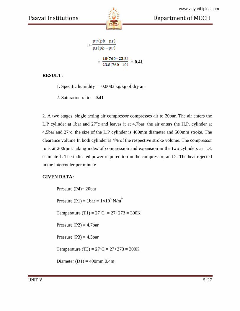
µ=
= = 0.41
RESULT:
1. Specific humidity 0.0083 kg/kg of dry air
2. Saturation ratio. =0.41
2. A two stages, single acting air compressor compresses air to 20bar. The air enters the
L.P cylinder at 1bar and 27oc and leaves it at 4.7bar. the air enters the H.P. cylinder at
4.5bar and 27oc. the size of the L.P cylinder is 400mm diameter and 500mm stroke. The
clearance volume In both cylinder is 4% of the respective stroke volume. The compressor
runs at 200rpm, taking index of compression and expansion in the two cylinders as 1.3,
estimate 1. The indicated power required to run the compressor; and 2. The heat rejected
in the intercooler per minute.
GIVEN DATA:
Pressure (P4)= 20bar
Pressure (P1) = 1bar = 1×10⁵ N/m
2
Temperature (T1) = 27oC = 27+273 = 300K
Pressure (P2) = 4.7bar
Pressure (P3) = 4.5bar
Temperature (T3) = 27oC = 27+273 = 300K
Diameter (D1) = 400mm 0.4m
www.vidyarthiplus.com
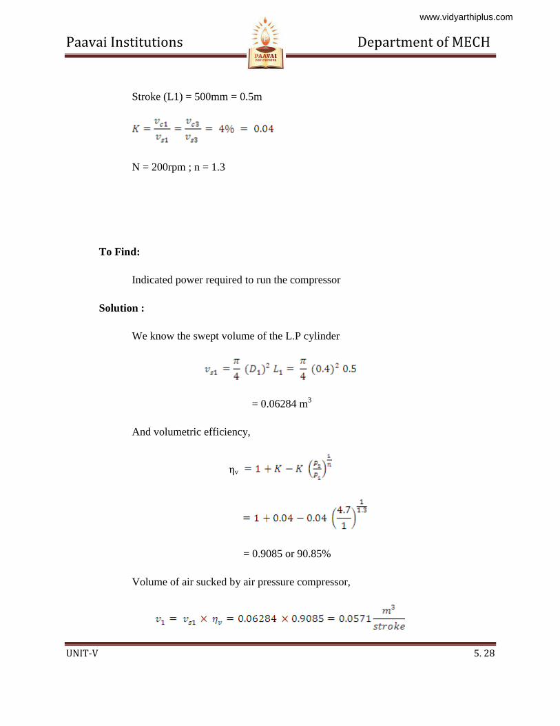
Paavai Institutions Department of MECH
UNIT-V 5. 28
Stroke (L1) = 500mm = 0.5m
N = 200rpm ; n = 1.3
To Find:
Indicated power required to run the compressor
Solution :
We know the swept volume of the L.P cylinder
= 0.06284 m3
And volumetric efficiency,
ηv
= 0.9085 or 90.85%
Volume of air sucked by air pressure compressor,
www.vidyarthiplus.com
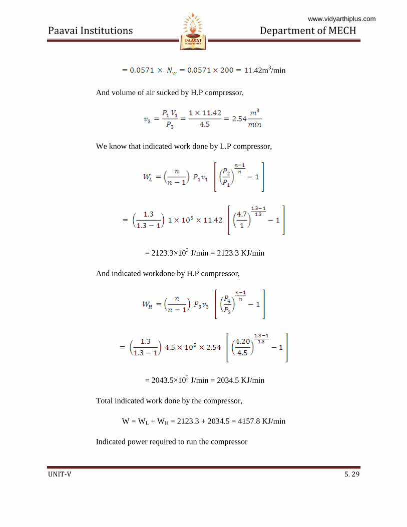
Paavai Institutions Department of MECH
UNIT-V 5. 29
1.42m3/min
And volume of air sucked by H.P compressor,
We know that indicated work done by L.P compressor,
= 2123.3×103 J/min = 2123.3 KJ/min
And indicated workdone by H.P compressor,
= 2043.5×103 J/min = 2034.5 KJ/min
Total indicated work done by the compressor,
W = WL + WH = 2123.3 + 2034.5 = 4157.8 KJ/min
Indicated power required to run the compressor
www.vidyarthiplus.com
Paavai Institutions Department of MECH
UNIT-V 5. 30
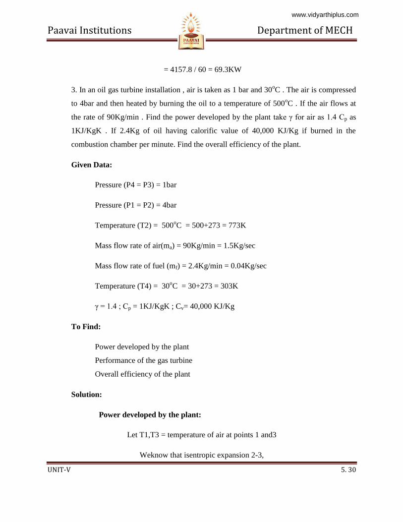
= 4157.8 / 60 = 69.3KW
3. In an oil gas turbine installation , air is taken as 1 bar and 30oC . The air is compressed
to 4bar and then heated by burning the oil to a temperature of 500oC . If the air flows at
the rate of 90Kg/min . Find the power developed by the plant take γ for air as 1.4 Cp as
1KJ/KgK . If 2.4Kg of oil having calorific value of 40,000 KJ/Kg if burned in the
combustion chamber per minute. Find the overall efficiency of the plant.
Given Data:
Pressure (P4 = P3) = 1bar
Pressure (P1 = P2) = 4bar
Temperature (T2) = 500oC = 500+273 = 773K
Mass flow rate of air(ma) = 90Kg/min = 1.5Kg/sec
Mass flow rate of fuel (mf) = 2.4Kg/min = 0.04Kg/sec
Temperature (T4) = 30oC = 30+273 = 303K
γ = 1.4 ; Cp = 1KJ/KgK ; Cv= 40,000 KJ/Kg
To Find:
Power developed by the plant
Performance of the gas turbine
Overall efficiency of the plant
Solution:
Power developed by the plant:
Let T1,T3 = temperature of air at points 1 and3
Weknow that isentropic expansion 2-3,
www.vidyarthiplus.com
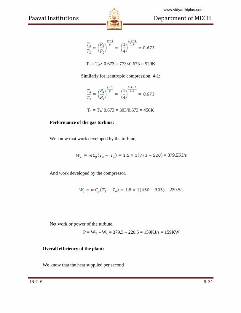
Paavai Institutions Department of MECH
UNIT-V 5. 31
T3 = T2× 0.673 = 773×0.673 = 520K
Similarly for isentropic compression 4-1:
T1 = T4/ 0.673 = 303/0.673 = 450K
Performance of the gas turbine:
We know that work developed by the turbine,
= 379.5KJ/s
And work developed by the compressor,
= 220.5/s
Net work or power of the turbine,
P = WT - Wc = 379.5 – 220.5 = 159KJ/s = 159KW
Overall efficiency of the plant:
We know that the heat supplied per second
www.vidyarthiplus.com
Paavai Institutions Department of MECH
UNIT-V 5. 32
= mf × C = 0.04× 40,000 = 1600 KJ/s
Therefore, overall efficiency of the plant,
ηo = 159/1600 = 0.099 or 9.99%
5.13 TWO MARK UNIVERSITY QUESTIONS:
www.vidyarthiplus.com
Paavai Institutions Department of MECH
UNIT-V 5. 33
Part-A (2 Marks)
1. Name four important properties of a good refrigerant
2. What is the difference between air conditioning and refrigeration?
3. What is the function of the throttling valve in vapour compression refrigeration system?
4. In a vapour compression refrigeration system, where the highest temperature will occur?
5. The vapour absorption system can use low-grade heat energy in the generator. Is true of false?
6. Name any four commonly used refrigerants.
7. Explain unit of Refrigeration.
8. Why throttle valve is used in place of expansion cylinder for vapour compression refrigerant
machine.
9. What are the effect pf super heat and suhcooling on .the vapour compression cycle?
10. What are the properties of good refrigerant?
11. How are air-conditioning systems classified?
12. How does humidity affect human comfort?
13. What are the various sources of heat gain of an air-conditioned space?
14. What do you mean by the term infiltration in heat load calculations?
www.vidyarthiplus.com
Paavai Institutions Department of MECH
UNIT-V 5. 34
5.14 UNIVERSITY ESSAY QUESTIONS:
Part-B (16 Marks)
1. Draw neat sketch of simple vapor compression refrigeration system and explain. (16)
2. Explain with sketch the working principle of aqua Ammonia refrigeration system. (16)
3. Explain with sketch the working principle of water-Lithium bromide refrigeration system. (16)
4. Briefly explain the cooling load calculation in air conditioning system. (16)
5. Explain winter, summer, and year round Alc system. (16)
6. Explain unitary Alc and central Alc system. (16)
7. Explain any four psychometric processes with sketch. (16)
8. A refrigeration system of 10.5 tonnes capacity at an evaporator temperature of -12°C and a
condenser temperature of 27°C is needed in a food storage locker. The refrigerant Ammonia is
sub cooled by 6°C before entering the expansion valve. The compression in the compressor is of
adiabatic type. Find 1. Condition of vapor at outlet of the compressor.2. Condition of vapor at the
entrance of the Evaporator 3.COP &power required. (16)
9. A sling psychrometer in a lab test recorded the following readings DBT=35°C,
WBT=25°CCalculate the following 1. Specific humidity 2. Relative humidity 3. Vapor density in
air 4. Dew point temperature 5. Enthalpy of mixing per kg of air .take atmospheric
pressure=1.0132 bar. (16)
www.vidyarthiplus.com
Paavai Institutions Department of MECH
UNIT-V 5. 35
www.vidyarthiplus.com