Embed Size (px)
Citation preview

Approved Continuing Education for Licensed Professional Engineers
Improving Fan System Performance
Four (4) Continuing Education Hours Course #ME1270
EZ-pdh.com Ezekiel Enterprises, LLC
301 Mission Dr. Unit 571 New Smyrna Beach, FL 32170
800-433-1487 [email protected]

Improving Fan System Performance Ezekiel Enterprises, LLC
ii
Course Description: The Improving Fan System Performance course satisfies four (4) hours of professional development. The course is designed as a distance learning course that overviews fan system performance and practical guidelines for increasing system efficiency.
Objectives: The primary objective of this course is to enable the student to understand fan systems, their components and operation, and various methods and guidelines to improve the performance for new or existing systems.
Grading:
Students must achieve a minimum score of 70% on the online quiz to pass this course. The quiz may be taken as many times as necessary to successful pass and complete the course. A copy of the quiz questions are attached to last pages of this document.

Improving Fan System Performance Ezekiel Enterprises, LLC
iii
Table of Contents Improving Fan System Performance
Introduction ........................................................................... 1
Fans ............................................................................... 1
Fan Performance Curves ................................................. 4
Fan System Components ................................................. 7
Assessing Fan System Needs ......................................... 13
Fan Types ..................................................................... 15
Basic Maintenance ....................................................... 21
Common Fan Systems Problems .................................... 25
Indications of Oversized Fans ........................................ 29
System Leaks ................................................................ 33
Configurations to Improve Fan System Efficiency ........... 35
Controlling Fans with Variable Loads ............................. 39
Fan Drive Options ......................................................... 43
Multiple-Fan Arrangements .......................................... 47
Fan System Economics .................................................. 50
Fan System Terminology ............................................... 54
Quiz Questions ..................................................................... 61

Fans are widely used in industrial and commercial applications. From shop ventilation to material handling to boiler applications, fans are critical for process support and human health. In the manufacturing sector, fans use about 78.7 billion kilowatt-hours2 of energy each year. This con-sumption represents 15 percent of the electricity used by motors.3 Similarly, in the commercial sector, electricity needed to operate fan motors composes a large portion of the energy costs for space conditioning.
Performance may range from “free air” to several pounds per square inch gage (psig), with airflow from a few cubic feet per minute (cfm) to more than 1 million cfm. Pressures above 15 psig generally require air compressors.
In manufacturing, fan reliability is critical to plant operation. For example, where fans serve material handling applications, fan failure will immediately create a process stoppage. In industrial ventilation applications, fan failure will often force a process to be shut down (although there is often enough time to bring the process to an orderly stoppage). Even in heating and cooling applications, fan operation is essential to maintain a productive work environment. Fan failure leads to conditions in which worker productivity and product quality declines. This is especially true for some production applications in which air cleanliness is critical to minimizing production defects (for example, plastics injection molding and electronic component manufacturing).
In each case, fan operation has a significant impact on plant production. The importance of fan reliability
often causes system designers to design fan systems conservatively. Concerned about beingresponsible for under-performing systems, designerstend to compensate for uncertainties in the designprocess by adding capacity to fans. Unfortunately,oversizing fan systems creates problems that canincrease system operating costs while decreasingfan reliability.
Fans that are oversized for their service requirementsdo not operate at their best efficiency points. Insevere cases, these fans may operate in an unstablemanner because of the point of operation on thefan airflow-pressure curve. Oversized fans generateexcess flow energy, resulting in high airflow noiseand increased stress on the fan and the system.Consequently, oversized fans not only cost more topurchase and to operate, they create avoidablesystem performance problems. The use of a “systems approach” in the fan selection processwill typically yield a quieter, more efficient, andmore reliable system.
Fans
There are two primary types of fans: centrifugaland axial. These types are characterized by thepath of the airflow through the fan. Centrifugalfans use a rotating impeller to increase the velocityof an airstream. As the air moves from the impellerhub to the blade tips, it gains kinetic energy. Thiskinetic energy is then converted to a static pressureincrease as the air slows before entering the discharge.Centrifugal fans are capable of generating relativelyhigh pressures. They are frequently used in “dirty”airstreams (high moisture and particulate content),in material handling applications, and in systemsat higher temperatures.
Introduction to Fan Systems
Introduction to Fan Systems
1

Improving Fan System Performance
Axial fans, as the name implies, move an airstreamalong the axis of the fan. The air is pressurized bythe aerodynamic lift generated by the fan blades,much like a propeller and an airplane wing.Although they can sometimes be used interchange-ably with centrifugal fans, axial fans are commonlyused in “clean air,” low-pressure, high-volumeapplications. Axial fans have less rotating mass andare more compact than centrifugal fans of compa-rable capacity. Additionally, axial fans tend to havehigher rotational speeds and are somewhat noisierthan in-line centrifugal fans of the same capacity;however, this noise tends to be dominated by highfrequencies, which tend to be easier to attenuate.
◆ Fan SelectionFan selection is a complex process that starts witha basic knowledge of system operating requirementsand conditions such as airflow rates, temperatures,pressures, airstream properties, and system layout.The variability of these factors and other consider-ations, such as cost, efficiency, operating life,maintenance, speed, material type, space con-straints, drive arrangements, temperature, andrange of operating conditions, complicate fanselection. However, knowledge of the importantfactors in the fan selection process can be helpfulfor the purposes of reducing energy consumptionduring system retrofits or expansions. Often, a fantype is chosen for nontechnical reasons, such asprice, delivery, availability, or designer or operatorfamiliarity with a fan model. If noise levels, energycosts, maintenance requirements, system reliability,or fan performance are worse than expected, thenthe issue of whether the appropriate fan type wasinitially selected should be revisited.
Fans are usually selected from a range of modelsand sizes, rather than designed specifically for a particular application. Fan selection is based on calculating the airflow and pressure require-ments of a system, then finding a fan of the rightdesign and materials to meet these requirements.Unfortunately, there is a high level of uncertaintyassociated with predicting system airflow and pressure requirements. This uncertainty, combinedwith fouling effects and anticipated capacityexpansion, encourages the tendency to increasethe specified size of a fan/motor assembly.
Designers tend to protect against being responsible for inadequate system performance by “over-specifying.” However, an oversized fan/motor assembly creates a different set of operating problems, including inefficient fan operation, excess airflow noise, poor reliability, and pipe/duct vibrations. By describing some of the problems and costs associated with poor fan selection, this course is intended to help designers and oper-ators improve fan system performance through bet-ter fan selection and improved operating and maintenance practices.
Noise. In industrial ventilation applications, noise can be a significant concern. High acoustic levels promote worker fatigue. The noise generated by a fan depends on fan type, airflow rate, and pressure. Inefficient fan operation is often indicated by a comparatively high noise level for a particular fan type.
If high fan noise levels are unavoidable, then ways to attenuate the acoustic energy should be considered. Noise reduction can be accomplished by several methods: insulating the duct; mounting the fan on a soft material, such as rubber or suit-able spring isolator as required to limit the amount of transmitted vibration energy; or installing sound damping material or baffles to absorb noise energy.
Rotational Speed. Fan rotational speed is typically measured in revolutions per minute (rpm). Fan rotational speed has a significant impact on fan performance, as shown by the following fan laws:
Introduction to Fan Systems
RPMfinalAirflowfinal = Airflowinitial ( )
RPMinitial
RPMfinalPressurefinal = Pressureinitial ( )
2
RPMinitial
RPMfinalPowerfinal = Powerinitial ( )3
RPMinitial
2

Rotational speed must be considered concurrentlywith other issues, such as variation in the fan load,airstream temperature, ambient noise, andmechanical strength of the fan.
Variations and uncertainties in system requirementsare critical to fan type and fan rotational speedselection. Fans that generate high airflow at relatively low speeds (for example, forward-curvedblade centrifugal fans) require a relatively accurateestimate of the system airflow and pressure demand.If, for some reason, system requirements are uncertain, then an improper guess at fan rotationalspeed can cause under-performance or excessiveairflow and pressure.
Airstream temperature has an important impact onfan-speed limits because of the effect of heat onthe mechanical strength of most materials. At hightemperatures, all materials exhibit lower yieldstrengths. Because the forces on shafts, blades, andbearings are proportional to the square of the rotational speed, high-temperature applications areoften served by fans that operate at relatively lowspeeds.
Airstream Characteristics. Moisture and particulatecontent are important considerations in selectingfan type. Contaminant build-up on fan blades cancause severe performance degradation and fanimbalance. Build-up problems are promoted by ashallow blade angle with surfaces that allow con-taminants to collect. Fans with blade shapes thatpromote low-velocity air across the blades, such asbackward inclined fans, are susceptible to contaminant build-up. In contrast, radial tip fansand radial blade fans operate so that airflow acrossthe blade surfaces minimizes contaminant build-up.These fans are used in “dirty” airstreams and inmaterial handling applications.
Corrosive airstreams present a different set of problems. The fan material, as well as the fan type,must be selected to withstand corrosive attack.Also, leakage into ambient spaces may be a concern, requiring the fan to be equipped with ashaft seal. Shaft seals prevent or limit leakage fromaround the region where the drive shaft penetratesthe fan housing. For example, in corrosive environ-ments fans can be constructed with expensive alloysthat are strong and corrosion resistant, or they can
be less expensively constructed with fiberglass-reinforced plastic or coated with a corrosion-resistant material. Because coatings are often lessexpensive than superalloy metals, fan types thatwork well with coatings (for example, radial fanblades because of their simple shape) are widelyused in corrosive applications; however, wear willreduce the reliability of coatings. Alternately, mate-rials such as reinforced fiberglass plastics havebeen developed for fan applications and function effectively in many corrosive environments.However, there may be size and speed limitationsfor composite materials and plastic materials.
Airstreams with high particulate content levels canalso be problematic for the fan drive train. In directdrive axial fans, the motor is exposed to theairstream. Sealed motors can be used in theseapplications but tend to be more expensive and, in the event of lost seal integrity, they are suscepti-ble to expensive damage. In axial fans, belt drivesoffer an advantage by removing the motor from theairstream. In centrifugal fans, the particulate content is less of a factor because the motor orsheave can be located outside of the fan enclosureand connected to the impeller through a shaft seal.Gear drives are occasionally used in applicationswhere speed reduction is required but the use of belt drives is unfeasible because of access or maintenance requirements.
In flammable environments, fans are usually constructed of nonferrous alloys to minimize therisk of sparks caused by metal-to-metal contact. Insome applications, certain components of the fancan be fabricated out of spark-resistant materials.Fans that operate in flammable environmentsshould be properly grounded, including rotatingcomponents, to minimize sparking because of stat-ic discharge.
Temperature Range. To a large degree, temperaturerange determines fan type and material selection.In high-temperature environments, many materialslose mechanical strength. The stresses on rotatingcomponents increase as the fan’s operating speedincreases. Consequently, for high-temperatureapplications, the fan type that requires the lowestoperating speed for a particular service is oftenrecommended. Radial blade fans can be ruggedlyconstructed and are frequently used in
Introduction to Fan Systems
3

Improving Fan System Performance
high-temperature environments. Component materials also significantly influence a fan’s ability to serve in high-temperature applications, and different alloys can be selected to provide the necessary mechanical properties at elevated temperatures.
Variations in Operating Conditions. Applications that have widely fluctuating operating requirements should not be served by fans that have unstable operating regions near any of the expected operating conditions. Because axial, backward-inclined airfoil, and forward-curved fans tend to have unstable regions, these fans are not recom-mended for this type of service unless there is a means of avoiding operation in the unstable region, such as a recirculation line, a bleed fea-ture, or some type of anti-stall device.
Space Constraints. Space and structural constraints can have a significant impact on fan selection. In addition to dimensional constraints on the space available for the fan itself, issues such as mainte-nance access, foundation and structural support requirements, and ductwork must be considered. Maintenance access addresses the need to inspect, repair, or replace fan components. Because down-time is often costly, quick access to a fan can pro-vide future cost savings. Foundation and structural requirements depend on the size and weight of a fan. Selecting a compact fan can free up valuable floorspace. Fan weight, speed, and size usually determine the foundation requirements, which, in turn, affect installation cost.
If the available space requires a fan to be located in a difficult configuration (for example, with an elbow just upstream or downstream of a fan), then some version of a flow straightener should be considered to improve the operating efficiency. Because non-uniform airflow can increase the pres-sure drop across a duct fitting and will degrade fan performance, straightening the airflow will lower operating costs.
An important tradeoff regarding space and fan systems is that the cost of floor space often motivates designers and architects to configure a fan system within a tight space envelope. One way to accomplish this is to use small-radius elbows,
small ducts, and very compact fan assemblies.Although this design practice may free up floorspace, the effect on fan system performance can besevere in terms of maintenance costs. The use ofmultiple elbows close to a fan inlet or outlet cancreate a costly system effect, and the added pressure drops caused by small duct size or acramped duct configuration can significantlyincrease fan operating costs. System designersshould include fan system operating costs as aconsideration in configuring fan assemblies andductwork.
Fan Performance Curves
Fan performance is typically defined by a plot ofdeveloped pressure and power required over arange of fan-generated airflow. Understanding thisrelationship is essential to designing, sourcing, andoperating a fan system and is the key to optimumfan selection.
Best Efficiency Point. Fan efficiency is the ratio ofthe power imparted to the airstream to the powerdelivered by the motor. The power of the airflow isthe product of the pressure and the flow, correctedfor units consistency. The equation for total efficiency is:
An important aspect of a fan performance curve is the best efficiency point (BEP), where a fan operates most cost-effectively in terms of bothenergy efficiency and maintenance considerations.Operating a fan near its BEP improves its performance and reduces wear, allowing longerintervals between repairs. Moving a fan’s operatingpoint away from its BEP increases bearing loadsand noise.
Another term for efficiency that is often used withfans is static efficiency, which uses static pressureinstead of total pressure in the above equation.When evaluating fan performance, it is importantto know which efficiency term is being used.
Introduction to Fan Systems
Total Pressure x AirflowTotal Efficiency =
bhp x 6,362
Where: Total Pressure is in inches of waterAirflow is in cubic feet per minute (cfm)bhp is brake horsepower
4
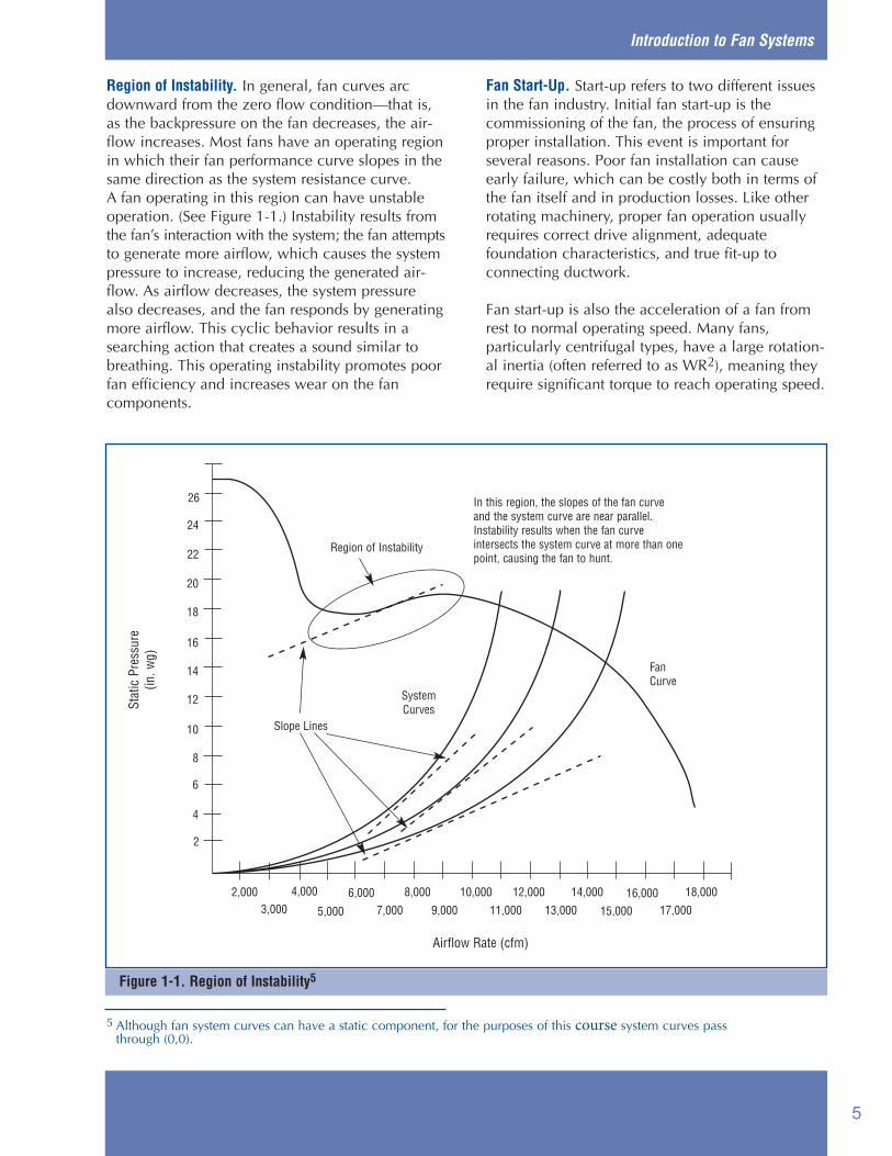
Figure 1-1. Region of Instability5
Region of Instability. In general, fan curves arcdownward from the zero flow condition—that is,as the backpressure on the fan decreases, the air-flow increases. Most fans have an operating regionin which their fan performance curve slopes in thesame direction as the system resistance curve. A fan operating in this region can have unstableoperation. (See Figure 1-1.) Instability results fromthe fan’s interaction with the system; the fan attemptsto generate more airflow, which causes the systempressure to increase, reducing the generated air-flow. As airflow decreases, the system pressurealso decreases, and the fan responds by generatingmore airflow. This cyclic behavior results in asearching action that creates a sound similar tobreathing. This operating instability promotes poorfan efficiency and increases wear on the fan components.
Fan Start-Up. Start-up refers to two different issues in the fan industry. Initial fan start-up is the commissioning of the fan, the process of ensuringproper installation. This event is important for several reasons. Poor fan installation can causeearly failure, which can be costly both in terms ofthe fan itself and in production losses. Like otherrotating machinery, proper fan operation usuallyrequires correct drive alignment, adequate foundation characteristics, and true fit-up to connecting ductwork.
Fan start-up is also the acceleration of a fan fromrest to normal operating speed. Many fans, particularly centrifugal types, have a large rotation-al inertia (often referred to as WR2), meaning theyrequire significant torque to reach operating speed.
Introduction to Fan Systems
5 Although fan system curves can have a static component, for the purposes of this course system curves passthrough (0,0).
Slope Lines
2,000 4,0003,000 13,000 15,000 17,00011,0005,000 7,000 9,000
6,000 8,000 10,000 12,000 14,000 16,000 18,000
Region of Instability
SystemCurvesSt
atic
Pre
ssur
e(in
. wg)
Airflow Rate (cfm)
FanCurve
26
24
22
20
18
16
14
12
10
8
6
4
2
In this region, the slopes of the fan curveand the system curve are near parallel.Instability results when the fan curveintersects the system curve at more than onepoint, causing the fan to hunt.
5

Improving Fan System Performance
In addition to the WR2 load, the air mass movedby the fan also adds to the start-up torque require-ments on the fan motor. Although rotational inertiais not typically a problem in heating, ventilation,and air conditioning (HVAC) applications, it maybe a design consideration in large industrial appli-cations. Proper motor selection is essential in ensuring that the fan can be brought to its operating speed and that, once there, the motoroperates efficiently.
Because the start-up current for most motors is 2 to 5 times the running current, the stress on themotor can be significantly reduced by starting afan under its minimum mechanical load andallowing the motor to achieve normal operatingspeed more quickly than when under full load. In many applications, system dampers can be positioned to reduce the load on the fan motorduring start-up. For example, the power requiredby a centrifugal fan tends to increase with increasingflow (although in “non-overloading” fan types, thepower drops off after reaching a peak). In axialfans, the power tends to decrease with increasingflow. Consequently, for most centrifugal fan types,large fan start-ups should be performed withdownstream dampers closed, while for most axialfan types, start-ups should be performed with thesedampers open. However, there are exceptions tothese guidelines, and the actual power curve forthe fan should be evaluated to determine how tosoften the impact of a large fan start-up.
The power surges that accompany the starting oflarge motors can create problems. Among theeffects of a large start-up current are power qualityproblems and increased wear on the electrical sys-tem. In response to increasing demand for equip-ment that minimizes the problems associated withlarge motor starts, electrical equipment manufac-turers are offering many different technologies,including special devices known as soft starters, toallow gradual motor speed acceleration. A keyadvantage of variable frequency drives (VFDs) isthat they are often equipped with soft starting fea-tures that decrease motor starting current to about1.5 to 2 times the operating current. Although VFDsare primarily used to reduce operating costs, theycan significantly reduce the impact of fan starts onan electrical system.
In axial fan applications, controllable pitch fans offer a similar advantage with respect to reducing start-up current. Shifting the blades to a low angle of attack reduces the required start-up torque of the fan, which allows the motor to reach operating speed more quickly.
System Effect. The system effect is the change in system performance that results from the interaction of system components. Typically, during the design process, the system curve is calculated by adding the losses of each system component (dampers, ducts, baffles, filters, tees, wyes, elbows, grills, louvers, etc.). The governing equation for pressure loss across any particular component is:
The result of this equation is a parabolic line, as shown by the system curve in Figure 1-2. This system curve assumes all components display pressure loss characteristics according to their loss coefficients. However, in reality, non-uniform airflow profiles that are created as the airstream develops swirls and vortices cause system components to exhibit losses that are higher than their loss coefficients. The overall effect of these added losses is to move the system curve up, as shown by the corrected system curve in Figure 1-2.
The system effect can be minimized by configuring the system so that the flow profile remains as uniform as possible. However, if space constraints prevent an ideal system layout, then system effect consequences should be incorporated into the fan selection process.
Introduction to Fan Systems
V∆p = C ( )2ρ
1,097
Where: ∆p = pressure loss in inches of water gage(in. wg)
C = loss coefficient for the componentV = velocity in feet per minuteρ = density of the airstream (0.075 pounds
per cubic foot at standard conditions)
6

Figure 1-2. System Effect for a Typical Fan and System
The system effect can be particularly problematicwhen the airflow into or out of a fan is disruptedinto a highly non-uniform pattern. Poor configurationof ductwork leading to or from a fan can severelyinterfere with a fan’s ability to efficiently impartenergy to an airstream. For example, placing anelbow close to the fan outlet can create a systemeffect that decreases the delivered flow by up to30 percent. This can require an increase in fanspeed, which in turn results in an increase inpower and a decrease in system efficiency.
Although underestimating the system effect causes insufficient air delivery, many designersovercompensate for it and other uncertainties by selecting oversized fans. This practice createsproblems such as high energy costs, high mainte-nance, and reduced system reliability. A more reasonable approach is to combine proper systemlayout practices with an accurate estimate of thesystem effect to determine an appropriate fan size.
Fan System Components
A typical fan system consists of a fan, an electric motor, a drive system, ducts or piping, flow control devices, and air conditioning equipment (filters, cooling coils, heat exchangers, etc.). An example system is illustrated in a diagram on page 8.
To effectively improve the performance of fan systems, designers and operators must understand how other system components function as well. The “systems approach” requires knowing the interaction between fans, the equipment that supports fan operation, and the components that are served by fans.
Prime Movers. Most industrial fans are driven by alternating current (AC) electric motors. Most are induction motors supplied with three-phase, 240- or 480-volt power. Because power supplies are typically rated at slightly higher voltages than motors because of anticipated voltage drops in the
Introduction to Fan Systems
System Curve (with system effect)
System Curve(as calculated)
Expected Performance
Actual Performance
Fan Curve
26
24
22
20
18
16
14
12
10
8
6
4
2
Stat
ic P
ress
ure
(in. w
g)
2,000 4,000
3,000 13,000 15,000 17,00011,0005,000 7,000 9,000
6,000 8,000 10,000 12,000 14,000 16,000 18,000
Airflow Rate (cfm)
7

Improving Fan System Performance
distribution system, motors are typically rated at230 or 460 volts. In recent years, because ofefforts by the National Electrical ManufacturersAssociation (NEMA) and motor manufacturers, theefficiency of general-purpose motors has signifi-cantly improved. These improvements are alsoattributable to the Energy Policy Act (EPAct), whichfor most motors went into effect in October 1997.To improve motor efficiency, motor manufacturershave modified motor designs and incorporatedbetter materials, resulting in slight changes inmotor operating characteristics. Although initialcosts of the motors have increased 10 to 20 per-cent, for high run-time applications, improvementsin motor efficiency create very attractive paybacksthrough lower operating costs.
A characteristic of induction motors is that theirtorque is directly related to slip, or the differencebetween the speed of the magnetic field and thespeed of the motor shaft. Consequently, in many
fans, actual operating speeds are usually around 2 percent less than their nominal speeds. Forexample, a theoretical four-pole induction motorwith no slip would rotate at 1,800 rpm with a 60-hertz power supply; however, rated operatingspeeds for this motor are usually around 1,750 rpm,indicating that slip rates are a little over 2.7 percentat rated load. Fans that are driven by older motorsare probably operating at much lower efficienciesand at higher levels of slip than what is availablefrom new motors.
Upgrading to a new motor can reduce operatingcosts, because of improved motor efficiency, whileoffering slightly improved fan performance. EPAct-efficiency motors operate with less slip, whichmeans fans rotate at slightly higher speeds. Forapplications that can effectively use this additionaloutput, this high efficiency can be attractive.However, if the additional output is not useful, theadded power consumption increases operating costs.
Introduction to Fan Systems
Outlet Diffusers
Filter
Inlet Vanes
Centrifugal Fan
Belt DriveMotor
Motor Controller
Heat Exchanger
Turning Vanes(typically used onshort-radius elbows)
Variable Frequency Drive
Baffles
Figure 1-3. Example Fan System Components
8

Another component of the prime mover is the motorcontroller. The controller is the switch mechanismthat receives a signal from a low power circuit,such as an on/off switch, and energizes or de-ener-gizes the motor by connecting or disconnectingthe motor windings to the power line voltage.Soft starters are electrical devices that are ofteninstalled with a motor controller to reduce theelectrical stresses associated with the start-up oflarge motors. In conventional systems, the high in-rush and starting currents associated with mostAC motors creates power quality problems, such as voltage sag. Soft starters gradually ramp up the voltage applied to the motor, reducingthe magnitude of the start-up current. As industrialfacilities increase the use of computer-basedequipment and control systems, soft starters arebecoming important parts of many motor controlsystems. In fact, a major advantage associated withmost VFDs is that they often have built-in, soft-startcapabilities.
Another common characteristic of motors used infan applications is multiple speed capability.Because ventilation and air-moving requirementsoften vary significantly, the ability to adjust fanspeed is useful. Motors can be built to operate atdifferent speeds in two principal ways: as a singleset of windings equipped with a switch that ener-gizes or de-energizes an additional set of poles, orwith the use of multiple windings, each of whichenergizes a different number of poles. The firsttype of motor is known as a consequent polemotor and usually allows two operating speeds,one twice that of the other. The second type ofmotor can have two, three, or four speeds,depending on application. In general, multiple-speed motors are more costly and less efficient thansingle-speed motors. However, the flow controlbenefit of different motor speeds makes themattractive for many fan applications.
Drive System. The drive system often offers substantial opportunities to improve energy efficiency and to lower overall system operatingcosts. There are two principal types of drive systems:direct drive and belt drive. Gear drives are alsoused but are less common. In direct drive systems,the fan is attached to the motor shaft. This is a simple, efficient system but has less flexibility withrespect to speed adjustments.
Because most fans are operated with inductionmotors, the operating rotational speeds of direct-drive fans are limited to within a few percent ofthe synchronous motor speeds (most commonly1,200, 1,800, and 3,600 rpm). The sensitivity offan output to its operating rotational speed meansthat errors in estimating the performance require-ments can make a direct-drive system operate inef-ficiently (unlike belt drives, which allow fan rota-tional speed adjustments by altering pulley diame-ters). One way to add rotational speed flexibility toa direct-drive system is to use an adjustable speeddrive (ASD). ASDs allow a range of shaft speedsand are quite practical for systems that have varyingdemand. Although ASDs are generally not a prac-tical option for fans that are only required to oper-ate at one speed, ASDs can provide a highly effi-cient system for fans that operate over a range ofconditions.
In axial fans, direct drives have some importantadvantages. Applications with low temperaturesand clean system air are well-suited for directdrives because the motor mounts directly behindthe fan and can be cooled by the airstream. Thisspace-saving configuration allows the motor tooperate at higher-than-rated loads because ofadded cooling. However, accessibility to the motoris somewhat restricted.
Belt drives offer a key advantage to fan systems by providing flexibility in fan speed selection. Ifthe initial estimates are incorrect or if the systemrequirements change, belt drives allow flexibilityin changing fan speed. In axial fans, belt driveskeep the motor out of the airstream, which can bean advantage in high temperature applications, orin dirty or corrosive environments.
There are several different types of belt drives,including standard belts, V-belts, cogged V-belts,and synchronous belts. There are different cost andoperating advantages to each type. In general, synchronous belts are the most efficient, while V-belts are the most commonly used. Synchronousbelts are highly efficient because they use a mesh-type contact that limits slippage and can loweroperating costs. However, switching to synchronousbelts must be done with caution. Synchronousbelts usually generate much more noise than otherbelts. They also transfer shock loads through the
Introduction to Fan Systems
9

Improving Fan System Performance
drivetrain without allowing slip. These suddenload changes can be problematic for both motorsand fans. Another problem with synchronous beltsis the limited availability of pulley sizes. Becausethe pulleys have a mesh pattern, machining themalters the pitch diameter, which interferes withengagement. Consequently, pulleys are available in discrete sizes, which precludes an importantadvantage of belt drives: the ability to alter operatingrotational speeds by adjusting sheave diameters.Because of these factors, synchronous belts are notas widely used as V-belts in fan applications.
In contrast, V-belts are widely used because oftheir efficiency, flexibility, and robust operation. V-belts have a long history in industrial applications,which means there is a lot of industry knowledgeabout them. An important advantage to V-belts istheir protection of the drivetrain during suddenload changes. Service conditions that experiencesudden drivetrain accelerations cause acceleratedwear or sudden failure. While synchronous beltstend to transfer these shock loads directly to theshafts and motors, V-belts can slip, affording someprotection. Although they are less efficient thansynchronous belts, V-belts offer many advantagessuch as low cost, reliable operation, and operatingflexibility. In applications that use standard belts,upgrades to V-belts should be considered.
Although they are not commonly used, gear systemsoffer some advantages to belt systems. Gear systemstend to be much more expensive than belt drivealternatives; however, gears tend to require lessfrequent inspection and maintenance than beltsand are preferable in applications with severelylimited access. Gears also offer several motor/fan configurations, including in-line drives, parallel-offset drives, and 90-degree drives, each of whichmay provide an attractive advantage in some applications. Gear-system efficiency depends largelyon speed ratio. In general, gear efficiencies rangefrom 70 to 98 percent. In large horsepower (hp)applications (greater than 100 hp), gear systemstend to be designed for greater efficiency becauseof the costs, heat, and noise problems that resultfrom efficiency losses. Because gears require lubri-cation, gearbox lubricant must be periodicallyinspected and changed. Also, because gears—likesynchronous belts—do not allow slip, shock loadsare transferred directly across the drivetrain.
Ductwork or Piping. For most fan systems, air is directed through ducts or pipes. In general, ducts are made of sheet metal and used in low-pressure systems, while pipes are sturdier and used in higher-pressure applications. Because ducts are used for most air-moving applications, “duct” will be the common reference for this course; how-ever, most of the same principles can be applied to pipes.
In ventilation applications in which a fan pulls directly from a ventilated space on one side and discharges directly to an external space (like a wall-mounted propeller fan), duct losses are not a significant factor. However, in most applications, ducts are used on one or both sides of a fan and have a critical impact on fan performance. Friction between the airstream and the duct surface is usu-ally a significant portion of the overall load on a fan.
As a rule, larger ducts create lower airflow resistance than smaller ducts. Although larger ducts have higher initial costs in terms of material and installation, the reduced cost of energy because of lower friction offsets some of these costs and should be included during the initial design process and during system modification efforts.
Other considera-tions with ducts are their shape and leakage class. Round ducts have less surface area per unit cross sectional area than rectangular ducts and, as a result, have less leakage. In hot or cool airstreams, this surface area also influences the amount of heat transferred to the environment.
Duct leakage class, typically identified by the factor CL (which has units of cfm/linear foot) is an indicator of duct integrity. Variables that determineCL include the type of joints used in construction,the number of joints per unit length of duct, and the shape of the duct. Depending on the length of the duct system, leakage can account for a significant portion of a fan’s capacity. This is especially applicable to systems with rectangular ducts that have unsealed joints. In many cases, the system designer can improve the performance of the ventilation system by specifying ducts thathave low CLs.
Introduction to Fan Systems
10

Airflow Control Devices. Flow control devicesinclude inlet dampers on the box, inlet vanes at theinlet to the fan, and outlet dampers at the outlet ofthe fan. Inlet box dampers are usually parallelblade dampers. Inlet vanes adjust fan output in twoprincipal ways: by creating a swirl in the airflowthat affects the way in which the air hits the fanblades, or by throttling the air altogether, whichrestricts the amount of air entering the fan. Theinlet vanes and dampers must be designed forproper fan rotation and are to be installed in sucha way that these inlet vanes and dampers open inthe same direction as the fan rotation. The pre-rotation or swirl of the air helps reduce the brakehorsepower of the fan. If the inlet dampers on theinlet box are located too far away from the inlet ofthe fan, the effect of pre-rotation may be lost orreduced, and horsepower savings may be negligible.
The outlet damper, when used for controlling airflow, is usually of opposed-blade design for betterflow distribution on the discharge side of the fan.If the outlet damper is going to be used for open/close service or for isolating the fan, a parallel-blade discharge damper may be used. Typically,fans with inlet vanes provide better power savingswhile operating the fan at part load conditions, asopposed to fans with inlet box dampers operatingin a similar situation. Inlet vanes provide bettercontrollability with optimum power savings compared to other dampers. Outlet dampers adjustresistance to airflow and move the operating pointalong the fan’s performance curve. Because theydo not change air entry conditions, outlet dampersdo not offer energy savings other than shifting theoperating point along the fan horsepower curve.
Dampers can be used to throttle the air entering orleaving a fan and to control airflow in branches ofa system or at points of delivery. Dampers controlairflow by changing the amount of restriction in anairstream. Increasing the restriction creates a largerpressure drop across the damper and dissipates someflow energy, while decreasing the restriction reducesthe pressure differential and allows more airflow.
From a system perspective, proper use of damperscan improve energy efficiency over traditional systemdesigns, especially in HVAC systems. In variable-airvolume (VAV) systems, dampers are effective atrerouting airflow and at controlling the amount of air
delivered to a particular workspace. Because VAVsystems are much more energy efficient than theirprecursors (constant-volume or dual-supply systems),dampers can be used to lower system operating costs.
However, in many applications, dampers candecrease fan efficiency. Dampers decrease total fanoutput by increasing backpressure, which forcesthe operating point of a fan to shift to the left alongits performance curve. Often, as the fan operatingpoint moves to the left along its curve, it operatesless efficiently and, in some cases, may perform inan unstable manner. Unstable fan operation is theresult of an aerodynamic phenomenon in whichthere is insufficient air moving across the fan blades.The airflow rate surges back and forth resulting ininefficient performance, annoying noise character-istics, and accelerated wear on the fan drive system.
Another airflow control method that is availablefor axial fan applications is the use of variablepitch blades. Variable pitch fans control fan outputby adjusting the fan blade angle of attack withrespect to the incoming airstream. This allows thefan to increase or decrease its load in response tosystem demand. In effect, this method is similar tothat provided by inlet vanes, which adjust theangle of attack of the entering airstream by creat-ing a swirl in the airflow pattern. Variable pitchfans provide a highly efficient means of matchingfan output to system demand.
Another method of airflow control is fan speedadjustment. Recalling the fan laws, speed has alinear relationship with airflow, a second-orderrelationship with pressure, and a third-order relationship with power. By slowing or speedingup a fan, its output can be adjusted to match system demand. In general, fan speed adjustmentis the most efficient method of airflow control.
There are two primary speed control options: mul-tiple-speed motors and ASDs. Multiple-speed motorshave discrete speeds, such as “high,” “medium,”and “low.” Although these motors tend to besomewhat less efficient than single speed motors,they offer simplicity, operating flexibility, a relative-ly compact space envelope, and significant energysavings for fan systems with highly variable loads. ASDs include several different types of mechanicaland electrical equipment. The most common type
Introduction to Fan Systems
11

Improving Fan System Performance
Introduction to Fan Systems
of ASD is a VFD. VFDs control the frequency of the power supplied to a motor to establish its operating speed. Unlike multiple speed motors that operate at discrete speeds, VFDs allow motors to operate over a continuous range of speed. This flexibility provides accurate matching between fan output and the flow and pressure requirements of the system.
Air Conditioning and Process Equipment (Filters, Heat Exchangers, etc.). Other equipment commonly found in air-moving systems includes devices used to condition the airstream to obtain certain properties. Heat exchangers are used to heat or cool an airstream to achieve a particular temperature or to remove moisture. Filters are used to remove unwanted particles or gases. Conditioning equipment influences fan performance by providing flow resistance and, in some cases, by changing air density. Filters, including cyclone types or mesh types, inherently create pressure drops, which are often significant components of the overall system pressure drop. Mesh-type filters create increasingly large pressure drops as they accumulate particles. In many systems, poor performance is a direct result of inadequate attention to filter cleanliness.
Cyclone filters remove particulates by rapidly altering the direction of the airflow so that heavy particulates, unable to change direction quickly, get trapped. Although cyclone filters are less effective than mesh filters, they tend to require less maintenance and have more stable pressure-drop characteristics.
The effects of heating and cooling coils on fan system performance depend largely on where in the system the heat exchangers are located, the extent of the temperature change, and how the heat exchangers are constructed. Where there are large changes in airstream temperature, fan per-formance can change as the air density changes. Heat exchangers that have closely spaced fins can accumulate particulates and moisture that not only impact heat transfer properties, but also increase pressure losses.
12

Assessing Fan System Needs
There are three principal opportunities in the lifecycle of a system that can be used to improve fansystem performance:
■ During initial system design and fan selection
■ During troubleshooting to solve a systemproblem
■ During a system capacity modification.
◆ Initial Fan SelectionFan selection starts with a basic knowledge of system operating conditions: air properties (moisture content, temperature, density, contaminant level, etc.), airflow rate, pressure, and system layout. These conditions determine which type of fan—centrifugal or axial—is required to meet service needs.
Axial fans move air along the direction of the fan’s rotating axis, much like a propeller. Axial fans tend to be light and compact. Centrifugal fans accelerate air radially, changing the direction of the airflow. They are sturdy, quiet, reliable, and capable of operating over a wide range of conditions. Many factors are used to determine whether axial or centrifugal fans are more appropriate for certain applications.
After deciding which fan type is appropriate, the right size must be determined. Fans are usually selected on a “best-fit” basis rather than designed specifically for a particular application. A fan is chosen from a wide range of models based on its ability to meet the anticipated demands of a system. Fans have two mutually dependent outputs: airflow and pressure. The variability of these outputs and other factors, such as efficiency, operating life, and maintenance, complicate the fan selection process.
Tendency to Oversize. A conservative design tendency is to source a fan/motor assembly that will be large enough to accommodate uncertainties in system design, fouling effects, or future capacity increases. Designers also tend to oversize fans to protect against being responsible for inadequate system performance.
However, purchasing an oversized fan/motor assembly creates operating problems such as excess airflow noise and inefficient fan operation. The incremental energy costs of operating oversized fans can be significant.
◆ Troubleshooting a System ProblemSome fan system problems, such as abnormally highoperating and maintenance costs and ineffective air-flow control, are sufficiently troublesome to justifya system assessment. If the system problems aresignificant, then a change to the fan, its drive system,or the airflow control devices may be justifiable.
High Operating and Maintenance Costs. Unusuallyhigh operating costs are often caused by inefficientfan operation that, in turn, can be the result ofimproper fan selection, poor system design, orwasteful airflow control practices. Improper fanselection often means the fan is oversized for theapplication, resulting in high energy costs, highairflow noise, and high maintenance requirements.
Poor system design can lead to high operating and maintenance costs by promoting poor airflowconditions. For example, duct configurations thatcreate large system effect factors can cause significant efficiency and airflow losses.
An effective way of minimizing maintenance andoperating costs is to keep a fan operating within areasonable range of its best efficiency point (BEP).However, this practice is often difficult in systemsthat have changing demands.
Poor Airflow Control. Poor airflow control refers to a wide range of causes and problems, includinginadequate delivery to a system branch, surgingoperation, and high airflow noise.
Inadequate delivery may be the result of poor system balancing or leakage. If a branch has adamper that is stuck open or a duct develops alarge leak, then this branch may provide a lowresistance flow path that robs airflow from otherdelivery points. Fans typically react to this loss of
Assessing Fan System Needs
13

Improving Fan System Performance
backpressure by generating high airflow rates. In severe cases, many centrifugal fan motors willoverload if operated against little or no backpressure.If not corrected, an overloaded motor will typicallyshut itself down with thermal or current safetyswitches.
Several situations can cause surging. Fans in a par-allel configuration may be shifting load betweeneach other. A single fan may be operating in a stallcondition or hunting for the right operating pointalong an unstable part of its performance curve. Inthese cases, the system resistance is too high.
Electrical System Wear. Frequent start-ups of largeloads can add significant stress to an electrical system. The in-rush current and the starting currentfor motors can create voltage sags in the electricalsystem and cause the motor to run hot for severalminutes. In fan applications where sensitive loadscan be affected by fan start-ups, the use of softstarters should be considered. Soft starters are electrical devices that gradually ramp up the voltage to the fan motor, limiting the in-rush andstarting current. Soft starters can extend fan motorlife by keeping the motor temperature low.
Variable frequency drives (VFDs) are also com-monly used to soft start fans. By gradually bringingfan speed up to operating conditions, VFDs reducestress on the electrical system.
◆ System Capacity ChangeFor a system that is to be modified or upgraded, anassessment of the available fan capacity should beperformed. Unless the existing fan is considerablyoversized, added capacity requires the installationof a larger fan or an additional fan. Conversely, asystem with excess fan capacity can often beaccommodated by operating the fan at a slowerspeed. In these applications, the effects of operatinga motor at less than half its rated load should beconsidered. Recall that motor efficiency and powerfactor fall significantly when the motor is operatedbelow half its rating.
Higher Fan Rotational Speed. One option to accommodate the increased demand is to operatethe fan at a higher speed. In belt driven applications,the sheave diameters can be changed to increasefan speed. The relationship between fan speed andairflow rate is linear; however, the relationshipbetween fan speed and power consumption iscubed.
Consequently, increasing the airflow rate of the fanby increasing its speed requires significantly morepower and may require a larger motor. The struc-tural integrity of the rotating elements, bearings,shafts, and support structure needs to be evaluatedfor the higher speeds.
Lower Fan Rotational Speed. If the fan is oversizedfor normal operating conditions, the feasibility ofoperating it at lower rotational speeds should beconsidered. Reducing fan speed can significantlyreduce energy consumption. For example, accordingto the fan laws, reducing fan rotational speed by20 percent decreases fan power by 50 percent.Unfortunately, this speed reduction may causemotor efficiency and power factor to drop to lowlevels. The costs of inefficient operation and lowpower factor may justify motor replacement or theinstallation of a variable frequency drive.
Multiple Fans. Airflow rate can also be increased by installing a separate fan next to an existing one. Multiple-fan configurations have many advantages, including flexibility in meeting widely varying system demands and redundancy in case of equip-ment failure. When adding a fan to an existing system, the system can be configured so that both fans operate concurrently or either fan operates independently. The concurrent operation of two fans creates a combined performance curve that may be more appropriate for the system requirements than that of a single fan.
Fan Replacement. Replacing an existing fan with a different model is also an option. Selecting a new, larger fan requires consideration of the same factors that are involved in any initial fan selection. A new fan may be more feasible if the existing one has degraded or requires extensive refurbishment. In high run-time applications, the purchase of a new fan with an energy-efficient motor may provide an attractive payback.
Assessing Fan System Needs
RPMfinalPowerfinal = Powerinitial ( )3
RPMinitial
14
Fan Types
◆ Basic PrincipleFans can be classified primarily into two differenttypes: axial and centrifugal. Axial fans act like propellers, generating airflow along the directionof the fan’s axis. Centrifugal fans generate airflowby accelerating the airstream radially and convert-ing the kinetic energy into pressure. Axial and cen-trifugal fans have overlapping capabilities in termsof pressure, airflow, and efficiency; however, usu-ally they are not interchangeable.
Key impacts that determine which fan type is themost appropriate include technical and non-technical attributes. Technical considerationsinclude pressure, airflow rate, efficiency, spaceconstraints, noise generation, drive configuration,temperature range, variations in operating conditions,and tolerance to corrosive or particulate-ladenairstreams. Nontechnical reasons include cost,delivery time, availability, and designer/operatorfamiliarity with a fan model.
Understanding the principles of fan selection canbe helpful in correcting poor system performance,especially during retrofit or upgrade opportunities.If noise levels, energy costs, maintenance require-ments, or fan performance do not meet expectations,then a different type of fan may need to be considered.
◆ Centrifugal FansCentrifugal fans are the most commonly used typeof industrial fan. Centrifugal fans are capable ofgenerating high pressures with high efficiencies,and they can be constructed to accommodateharsh operating conditions. Centrifugal fans haveseveral types of blade shapes, including forward-curved, radial-blade, radial-tip, backward-inclined, backward-curved, and airfoil. Some centrifugal fantypes are capable of serving widely varying operatingconditions, which can be a significant advantage.
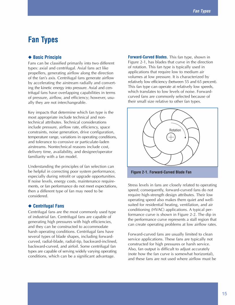
Forward-Curved Blades. This fan type, shown inFigure 2-1, has blades that curve in the directionof rotation. This fan type is typically used in applications that require low to medium air volumes at low pressure. It is characterized by relatively low efficiency (between 55 and 65 percent).This fan type can operate at relatively low speeds,which translates to low levels of noise. Forward-curved fans are commonly selected because oftheir small size relative to other fan types.
Stress levels in fans are closely related to operatingspeed; consequently, forward-curved fans do notrequire high-strength design attributes. Their lowoperating speed also makes them quiet and well-suited for residential heating, ventilation, and airconditioning (HVAC) applications. A typical per-formance curve is shown in Figure 2-2. The dip inthe performance curve represents a stall region thatcan create operating problems at low airflow rates.
Forward-curved fans are usually limited to cleanservice applications. These fans are typically notconstructed for high pressures or harsh service.Also, fan output is difficult to adjust accurately(note how the fan curve is somewhat horizontal),and these fans are not used where airflow must be
Fan Types
Figure 2-1. Forward-Curved Blade Fan
Rotation
15
Improving Fan System Performance
Fan Types
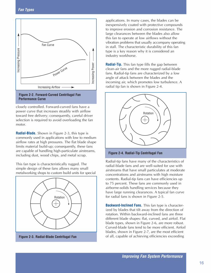
closely controlled. Forward-curved fans have apower curve that increases steadily with airflowtoward free delivery; consequently, careful driverselection is required to avoid overloading the fanmotor.
Radial-Blade. Shown in Figure 2-3, this type iscommonly used in applications with low to mediumairflow rates at high pressures. The flat blade shapelimits material build-up; consequently, these fansare capable of handling high-particulate airstreams,including dust, wood chips, and metal scrap.
This fan type is characteristically rugged. The simple design of these fans allows many small metalworking shops to custom build units for special
applications. In many cases, the blades can be inexpensively coated with protective compoundsto improve erosion and corrosion resistance. Thelarge clearances between the blades also allow this fan to operate at low airflows without thevibration problems that usually accompany operatingin stall. The characteristic durability of this fantype is a key reason why it is considered an industry workhorse.
Radial-Tip. This fan type fills the gap betweenclean-air fans and the more rugged radial-bladefans. Radial-tip fans are characterized by a lowangle of attack between the blades and the incoming air, which promotes low turbulence. Aradial tip fan is shown in Figure 2-4.
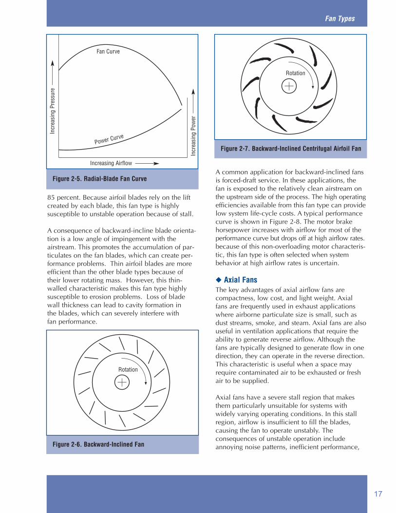
Radial-tip fans have many of the characteristics ofradial-blade fans and are well-suited for use withairstreams that have small particulates at moderateconcentrations and airstreams with high moisturecontents. Radial-tip fans can have efficiencies upto 75 percent. These fans are commonly used inairborne-solids handling services because theyhave large running clearances. A typical fan curvefor radial fans is shown in Figure 2-5.
Backward-Inclined Fans. This fan type is character-ized by blades that tilt away from the direction ofrotation. Within backward-inclined fans are threedifferent blade shapes: flat, curved, and airfoil. Flatblade types, shown in Figure 2-6, are more robust.Curved-blade fans tend to be more efficient. Airfoilblades, shown in Figure 2-7, are the most efficientof all, capable of achieving efficiencies exceeding
Figure 2-2. Forward-Curved Centrifugal FanPerformance Curve
Fan Curve
Increasing Airflow
Incr
easi
ng P
ower
Incr
easi
ng P
ress
ure
Power Curve
Figure 2-3. Radial-Blade Centrifugal Fan
Rotation
Figure 2-4. Radial-Tip Centrifugal Fan
Rotation
16
Fan Types
85 percent. Because airfoil blades rely on the liftcreated by each blade, this fan type is highly susceptible to unstable operation because of stall.
A consequence of backward-incline blade orienta-tion is a low angle of impingement with theairstream. This promotes the accumulation of par-ticulates on the fan blades, which can create per-formance problems. Thin airfoil blades are moreefficient than the other blade types because oftheir lower rotating mass. However, this thin-walled characteristic makes this fan type highlysusceptible to erosion problems. Loss of bladewall thickness can lead to cavity formation in the blades, which can severely interfere with fan performance.
A common application for backward-inclined fansis forced-draft service. In these applications, thefan is exposed to the relatively clean airstream onthe upstream side of the process. The high operatingefficiencies available from this fan type can providelow system life-cycle costs. A typical performancecurve is shown in Figure 2-8. The motor brakehorsepower increases with airflow for most of theperformance curve but drops off at high airflow rates.because of this non-overloading motor characteris-tic, this fan type is often selected when systembehavior at high airflow rates is uncertain.
◆ Axial FansThe key advantages of axial airflow fans are compactness, low cost, and light weight. Axialfans are frequently used in exhaust applicationswhere airborne particulate size is small, such asdust streams, smoke, and steam. Axial fans are also useful in ventilation applications that require theability to generate reverse airflow. Although thefans are typically designed to generate flow in onedirection, they can operate in the reverse direction.This characteristic is useful when a space mayrequire contaminated air to be exhausted or freshair to be supplied.
Axial fans have a severe stall region that makesthem particularly unsuitable for systems with widely varying operating conditions. In this stallregion, airflow is insufficient to fill the blades,causing the fan to operate unstably. The consequences of unstable operation includeannoying noise patterns, inefficient performance,
Figure 2-5. Radial-Blade Fan Curve
Fan Curve
Increasing Airflow
Incr
easi
ng P
ower
Power Curve
Figure 2-6. Backward-Inclined Fan
Rotation
Figure 2-7. Backward-Inclined Centrifugal Airfoil Fan
Rotation
Incr
easi
ng P
ress
ure
17

Improving Fan System Performance
Fan Types
and accelerated drivetrain wear. This problem ofstall can be solved in many axial fans by selectinga fan with an anti-stall device. These devices alterthe airflow patterns around the fan blades, allowingstable fan operation over the entire range of airflowand pressure.
Axial fans must rotate faster than comparable centrifugal fans to achieve the same airflow capacity.This characteristic makes them noisier than comparable centrifugal fans; however, the noisesignature is dominated by higher frequencies,which are easier to attenuate.
Propeller Fans. The simplest version of an axial fanis the propeller type, shown in Figure 2-9.
Propeller fans generate high airflow rates at lowpressures. Because propeller fans do not generatemuch pressure, they are usually not combined withextensive ductwork. Propeller fans tend to haverelatively low efficiencies, but they are inexpensivebecause of their simple construction. Propeller fanstend to be comparatively noisy, reflecting theirinefficient operation.
As shown in Figure 2-10, the power requirementsof propeller fans decrease with increases in airflow.They achieve maximum efficiency, near-free deliv-ery, and are often used in rooftop ventilation applications.
Tubeaxial Fans. A more complex version of a propeller fan is the tubeaxial fan. This type, shownin Figure 2-11, is essentially a propeller fan placedinside a cylinder. By improving the airflow
Figure 2-9. Propeller Fan Figure 2-11. Tubeaxial Fan
Figure 2-10. Propeller Fan Curve
Fan Curve
Increasing Airflow
Power Curve
Incr
easi
ng P
ress
ure
Airflow
Figure 2-8. Backward-Inclined Fan Curve
Fan Curve
Increasing Airflow
Power Curve
Incr
easi
ng P
ress
ure
Incr
easi
ng P
ower
18

Fan Types
characteristics, tubeaxial fans achieve higher pressures and better operating efficiencies thanpropeller fans.
Tubeaxial fans are used in medium-pressure, high-airflow rate applications and are well-suited forducted HVAC installations. The airflow profiledownstream of the fan is uneven, with a large rotational component. This airflow characteristic isaccompanied by moderate airflow noise.
Tubeaxial fans are frequently used in exhaustapplications because they create sufficient pressureto overcome duct losses and are relatively spaceefficient. Also, because of their low rotating mass,they can quickly accelerate to rated speed, whichis useful in many ventilation applications.
The performance curve for tubeaxial fans is shownin Figure 2-12. Much like propeller fans, tubeaxialfans have a pronounced instability region thatshould be avoided.
Tubeaxial fans can be either connected directly to amotor or driven through a belt configuration.Because of the high operating speeds of 2-, 4-, and6-pole motors, most tubeaxial fans use belt drivesto achieve fan speeds below 1,100 revolutions perminute.
Vaneaxial Fans. A further refinement of the axialfan is the vaneaxial fan. As shown in Figure 2-13,a vaneaxial fan is essentially a tubeaxial fan with
outlet vanes that improve the airflow pattern, converting the airstream’s kinetic energy to pressure.These vanes create an airflow profile that is comparatively uniform.
Vaneaxial fans are typically used in medium- tohigh-pressure applications, such as induced draftservice for a boiler exhaust. Like tubeaxial fans,vaneaxial fans tend to have a low rotating mass,which allows them to achieve operating speed relatively quickly. This characteristic is useful inemergency ventilation applications where quick airremoval or supply is required. Also, like other axialfans, vaneaxial fans can generate flow in reversedirection, which is also helpful in ventilation applications. Depending on the circumstances,these applications may require the supply of freshair or the removal of contaminated air.
Figure 2-13. Vaneaxial Fan
Airflow
Figure 2-12. Tubeaxial Fan Curve
Fan Curve
Increasing Airflow
Power Curve
Incr
easi
ng P
ress
ure
Incr
easi
ng P
ower
Figure 2-14. Vaneaxial Fan Curve
Fan Curve
Increasing Airflow
Power Curve
Incr
easi
ng P
ress
ure
Incr
easi
ng P
ower
19
Improving Fan System Performance
Fan Types
Vaneaxial fans are often equipped with variable-pitch blades, which can be adjusted to change theangle of attack to the incoming airstream. Variable-pitch blades can change the load on the fan, providing an effective and efficient method of air-flow control.
As shown in Figure 2-14, vaneaxial fans have performance curves that have unstable regions tothe left of the peak pressure. These fans are highlyefficient. When equipped with airfoil blades andbuilt with small clearances, they can achieve efficiencies up to 85 percent. Vaneaxial fans arefrequently connected directly to a motor shaft.
20

Basic Maintenance
◆ Maintenance ItemsCommon maintenance tasks on fan systemsinclude:
■ Periodic inspection of all system components■ Bearing lubrication and replacement■ Belt tightening and replacement■ Motor repair or replacement■ Fan cleaning.
The most costly consequence of improper maintenance is unscheduled downtime. Causes ofthis downtime vary according to the demands ofthe application. Because each system places partic-ular demands on its air-moving equipment, mainte-nance requirements vary widely.
◆ Maintenance SchedulesTo minimize the amount of unscheduled downtime,basic system maintenance should be performed atreasonable intervals, the length of which should bedetermined by either hours of operation or calendarperiods. The maintenance interval should be basedon manufacturer recommendations and experiencewith fans in similar applications.
Factors that should weigh into this schedule includethe cost of downtime, the cost and the risk of catastrophic failure, and the availability of back-upequipment. In systems that do not have abnormallysevere operating demands, a typical maintenanceschedule would include the items on the checklist.
Belt Inspection. In belt-driven fans, belts are usuallythe most maintenance-intensive part of the fanassembly. As belts wear, they tend to lose tension,reducing their power transmission efficiency. Even new, properly adjusted belts suffer losses of 5 to10 percent. As belt conditions degrade, theselosses increase. Because noise is one of the ways
in which the energy loss of belts is manifested,poor belt condition can add significantly to theambient noise level.
Belt inspection is particularly important to theoperation of large fans because of the size of thepower losses. For example, in a 200-horsepower(hp) fan, a 5 percent decrease in power transmis-sion efficiency results in a 10-hp loss, translating to $3,270 annually for a continuously operatingsystem.1
Basic Maintenance
Basic Maintenance Checklist❏ Belts. Check belt condition, tightness, and
alignment. Also check sheave condition.
❏ Bearings. Determine bearing condition bylistening for noises that indicate excessivewear, measuring bearing operating temperature,or by using a predictive maintenance technique,such as vibration analysis or oil analysis.Lubricate bearings in accordance with fanmanufacturer instructions. Replace bearings,if necessary.
❏ System Cleaning. Fans and system componentsthat are susceptible to contaminant build-upshould be cleaned regularly.
❏ Leaks. Check for ductwork leakage that canlead to energy losses and poor systemperformance.
❏ Motor Condition. Check the integrity of motorwinding insulation. Generally, these tests measureinsulation resistance at a certain voltage ormeasure the rate at which an applied voltagedecays across the insulation. Also, vibrationanalysis can indicate certain conditions withinthe motor windings, which can lead to earlydetection of developing problems.
1 Using $0.05/kilowatt-hour.
21

Improving Fan System Performance
Basic Maintenance
Although belt inspection and tightening is usuallya routine task for any mechanic, increased aware-ness of the costs associated with poorly adjustedbelts can improve the attention devoted to thismaintenance effort.
In multiple-belt arrangements, whenever one beltdegrades to the point of requiring replacement, allthe belts should be replaced at the same time. Asbelts wear and age, they exhibit different properties;consequently, replacing only one or two belts in amultiple-belt arrangement creates a risk of over-loading one or more of the belts. Exposing all thebelts to roughly the same operating time mini-mizes the risk of uneven loading.
Establishing proper belt tightness is essential tominimizing the energy losses associated with beltdrives. However, care should be taken to preventovertightening the belts. This leads to high radialbearing loads, accelerated wear, and shorter bearing replacement intervals.
Fan Cleaning. In many fans, performance decline islargely because of contaminant build-up on fanblades and other system surfaces. Contaminant build-up is often not uniform, resulting in imbalanceproblems that can result in performance problemsand drivetrain wear. Because fans are often used inventilation applications to remove airborne con-taminants, this problem can be particularly acute.Fans that operate in particulate-laden or high-mois-ture airstreams should be cleaned regularly.
Certain fan types, such as backward-inclined airfoil,are highly susceptible to build-up of particulates ormoisture. These build-ups disturb the airflow overthe blades, resulting in decreased fan efficiencyand higher operating costs.
In high-particulate or moisture-content applications,radial-blade, radial-tip, and forward-curved bladetype fans are commonly used because of their resist-ance to contaminant build-up. If, for some otherreason, a different type of fan is used in a high-par-ticulate or high-moisture service, then fan inspec-tion and cleaning should be performed more fre-quently than normal.
Leakage. System leaks degrade system performanceand increase operating costs. Leaks tend to develop
in flexible connections and in areas of a system that experience high vibration levels. Leakage decreases the amount of air delivered to the point of service; consequently, one of the first steps in troubleshooting a system that has experienced declining performance is to check the integrity of the ductwork.
Sources of leaks can be identified visually by inspecting for poorly fitting joints, and tears or cracks in ductwork and flexible joints. In systems with inaccessible ductwork, the use of temporary pressurization equipment can determine if the integrity of the system is adequate.
Bearing Lubrication. Worn bearings can create unsatisfactory noise levels and risk seizure. Bearings should be monitored frequently. Bearing lubrication should be performed in accordance with the manufacturer’s instructions. For example, for high-speed fans in severe environments, lubrication intervals can be necessary weekly or more often.
■ For oil-lubricated bearings, check the oil qualityand, if necessary, replace the oil.
■ For grease-lubricated bearings, check the greasequality and, if necessary, repack the bearings.Be careful not to over-grease bearings as thisinterferes with ball or roller motion and maycause overheating.
■ Ensure the bearings are adequately protectedfrom contamination.
In axial fans, anti-friction bearings (ball, roller-type)are predominantly used because of the need for arobust thrust bearing to handle the axial thrustload.
Motor Replacement. Even properly maintainedmotors have a finite life. Over time, winding insulation inevitably breaks down. Motors inwhich the winding temperatures exceed rated values for long periods tend to suffer acceleratedinsulation breakdown. When faced with the decision to repair or replace a motor, several factors must be considered, including motor size,motor type, operating hours, and cost of electricity.For example, in a motor application where the
22

Basic Maintenance
cost of electricity is $0.05/kilowatt-hour, the motor operates 4,000 hours each year at 75 percent rated load, and the rebuild cost is 60 percent of the price of a new motor, the calculated breakeven point between repair and replacement is 50 hp.2 Under these circumstances, in applications requiring less than 50 hp, replacement motors meeting Energy Policy Act (EPAct) efficiency requirements should be selected, while larger motors should be rebuilt.
Of course, each facility must establish its own repair/replace strategy. There are several resources that provide guidance in developing such a strategy.
For motor rewinds, ensure that the repair facility has a proper quality assurance program, because poor quality motor rewinds can compromise motor efficiency. Although motor rewinds are often cost-effective, motors that have been previously rewound can suffer additional efficiency losses during subsequent rewinds.
For motor replacements, high-efficiency motors should be considered. High-efficiency motors are generally 3 to 8 percent more efficient than standard motors. In high-use applications, this efficiency advantage often provides an attractive payback period. EPAct, which went into effect in October 1997, set minimum efficiency standards for most general-purpose motors from 1 to 200 hp.
The MotorMaster+ software program can be a valuable tool in selecting energy-efficient motors. The program allows users to compare motors and estimate energy costs and savings along with life-cycle costs. Because MotorMaster+ contains motor rotational speed data, it is useful in finding replacement motors that operate at the same speed
as the existing motor. This can help avoid theproblem of installing a motor that, because of itshigher operating speed, causes the fan to generatemore airflow and consume more energy than theprevious motor/fan combination. MotorMaster+ isavailable through the Industrial TechnologiesInformation Clearinghouse and can be downloadedfrom the BestPractices Web site atwww.oit.doe.gov/bestpractices.
Fan Replacement. Under most conditions, fan bladesshould last the life of the impeller. However, in harshoperating environments, erosion and corrosion canreduce fan-blade thickness, weakening the bladesand creating an impeller imbalance. In these cases,either the impeller should be replaced or an entirelynew fan should be installed.
◆ Predictive MaintenanceIn many applications, fan maintenance is reactiverather than proactive. For example, bearing lubrication is performed in response to audiblebearing noises. Fan cleaning is performed to correct an indication of poor fan performance orvibration because of dust build-up. Unfortunately,many fan system problems remain unaddresseduntil they become a nuisance, by which time theymay have resulted in significantly higher operatingcosts.
Vibration analysis equipment is essentially arefined extension of the human ear. By “listening”to the vibrations of a motor or similar piece ofmachinery, the instrumentation can detect theearly symptoms of a bearing problem, motor winding problem, or dynamic imbalance. By identifying problems before they become worse,repairs can be effectively scheduled, reducing therisk of catastrophic failure.
Fortunately, recent improvements in instrumentationand signal analysis software have increased theavailability of vibration monitoring and testingequipment. These devices can be permanentlyinstalled with a fan and incorporated into an alarmor safety shutdown system. Vibration monitorsoffer relatively inexpensive insurance for avoidingcostly failures and can improve the effectivenesswith which fan maintenance is planned.
2 HorsePower Bulletin, Advanced Energy (in cooperation with the U.S. Department of Energy).
23

Improving Fan System Performance
Basic Maintenance
Portable vibration instruments can also be used aspart of a facility’s preventive maintenance system.Vibrations measured during operation can be compared against a baseline set of data, usuallytaken when the machinery was first commissioned.Vibration signatures taken at different points in afan’s operating life can be evaluated to determinewhether a problem is developing and, if so, how fast.
◆ RecordsA written log or record documenting observationsand inspection results is a useful supplement to amaintenance schedule. Often a machinery problemwill develop over time. A history of the repairs,adjustments, or operator observations regardingthe conditions under which the problem becomesnoticeable improves the ability to effectivelyschedule a repair. The MotorMaster+ software contains an inventory module that allows the userto record maintenance and inspection results.
24

Common Fan System Problems
◆ Basic PrincipleLike most other rotating machinery, fans experience wear and require periodic maintenance and repairs. Dynamic surfaces in bearings and belt drives degrade over time. Fan blade surfaces may erode from abrasive particles in the airstream, and motors eventually require replacement or rewinding.
Although some degree of wear is unavoidable, operating the system at efficient levels reduces the risk of sudden equipment failure and can lower the cost and frequency of maintenance.
Fan system problems can be grouped into two principal categories: problems that are related to the fan/motor assembly and problems associated with the system. A systems approach is important to help understand the total costs and performance impacts of these problems.
◆ Fan/Motor Assembly ProblemsProblems with the fan/motor assemblies can result from improper component selection, poorinstallation, or poor maintenance.
Belt Drives. Belt drives are frequently the mostmaintenance-intensive component of a fan/motorassembly. Common problems include belt wear,noise, and rupture. Belt wear can lead to efficiencyand performance problems. As belt slippageincreases, it can translate directly into lower fanoutput. Insufficient belt tension can also causehigh noise levels through belt slap or slippage. In some cases, belts will develop one or moresmooth spots that lead to vibrations during fanoperation.
In contrast, belt tension that is too high increasesthe wear rate, increases load on the bearings, andcan create an increased risk of unexpected down-time.
In multiple-belt drive assemblies, uneven loadingof the belts causes uneven wear, which can affect
the life and reliability of the whole drive unit.Poor belt drive maintenance also promotes costlysystem operation. Contaminant build-up on thebelts often results in increased slippage and noisyoperation. The presence of abrasive particles tendsto accelerate belt wear.
Belts are not the only item in a belt drive assemblythat develop problems. The sheaves themselves are subject to wear and should be periodicallyinspected. Because sheave diameter has a signifi-cant effect on fan speed, the relative wear between the driven and the driving sheave can affect fanperformance.
Bearings. As with most rotating machinery, thebearings in a fan/motor assembly wear and, overtime, can create operating problems. To preventsuch problems from causing unplanned downtime,bearings should be a principal maintenance item.There are two primary bearing types in fan/motorcombinations: radial and thrust. In general, radialbearings tend to be less expensive than thrust bearings in terms of material cost and installationrequirements. Because of the nature of the airflow,axial fans typically require heavier thrust bearings.These bearings tend to be comparatively expensive,making proper fan operation and effective maintenance important.
Common bearing problems include noise, excessiveclearance, and, in severe cases, seizure. Becauseoperating conditions vary widely, the history ofother fans in similar applications should be used toschedule bearing replacement. Vibration analysistools can improve confidence in determining bearing condition and planning bearing work. Inoil-lubricated bearings, oil analysis methods canhelp evaluate bearing condition.
Motors. Even properly maintained motors have afinite life. Over time, winding insulation inevitablybreaks down. Motors in which the winding temperatures exceed rated values for long periodstend to suffer accelerated insulation breakdown.In motor applications below 50 horsepower, the
Common Fan System Problems
25

Improving Fan System Performance
Common Fan System Problems
common repair choice is simply to replace a motor with a new one; however, in larger applica-tions, rewinding an existing motor is often more economically feasible. Although motor rewinds are typically a cost-effective alternative, motors that have been previously rewound can suffer addition-al efficiency losses during subsequent rewinds.
For motor rewinds, ensure that the repair facility has a proper quality assurance program, because poor-quality motor rewinds can compromise motor efficiency.
For motor replacements, energy-efficient motors should be considered. A section of the national Energy Policy Act (EPAct) setting minimum efficiency standards for most common types of industrial motors went into effect in October 1997. EPAct should provide industrial end users with increased selection and availability of energy efficient motors. EPAct-efficient motors can be 3 to 8 percent more efficient than standard motors. In high run-time applications, this efficiency advantage often provides an attractive payback period.
The MotorMaster+ software program can be a valuable tool in selecting energy-efficient motors. The program allows users to compare motors and estimate energy costs and savings along with life cycle costs. It is available through the Information Clearinghouse and can be downloaded from the Web site at www.oit.doe.gov/bestpractices.
Contaminant Build-Up. Some fan types are susceptible to contaminant build-up. The tendency to suffer build-up is related to the velocity and angle of attack of the airflow with respect to the blades. In many cases, especially with backward-inclined blades, this build-up can significantly affect fan performance. Fan types that have blade shapes that discourage material accumulation (for example, radial and radial-tip types) are usually selected for applications in which the airstreams have high particulate or moisture content. However, even in relatively clean air applications, over time, particulate build-up can be a problem. Consequently, fan cleaning should be a part of the routine maintenance program.
In many heating and cooling system applications,highly efficient fan types, such as backward-inclined fans, are increasingly used to lower system energy consumption. An important component in this trend is the use of filters upstreamof the fans to lessen material build-up. While thesefilters can help maintain efficient fan performance,additional attention to filter cleaning and replace-ment is required to avoid the pressure drops andenergy losses that result from clogged filters.
Fan Degradation. In airstreams that have corrosivegases or abrasive particles, fan blade degradationcan present a threat to reliable operation. As fanblades degrade, the airflow over the surfacesbecomes disrupted and the fan imparts energy lessefficiently to the airstream. Certain blade types areparticularly susceptible to erosion because of theangle of attack with the airstream. In applicationswhere higher-than-expected blade degradation hasoccurred, different fan types or fan materials shouldbe considered. Many fan manufacturers havedeveloped materials and coatings that solve thisproblem.
◆ System ProblemsPoor system performance can be caused by several factors, including improper system designand component selection, incorrect installationpractices, and inadequate maintenance. Impropersystem design usually means the system is configured so that it has high system effect factors(SEFs) that result in high operating costs, systemleakage, and noisy system operation. Poor component selection includes oversizing fans orusing ineffective or wasteful flow control devices.
Improper installation practices include on-sitemodifications to the duct system that result in highSEFs, improper fan rotational speed selection, andincorrect fan rotation.
Inadequate maintenance often means a lack ofbearing lubrication and fan cleaning. Contaminantaccumulation on fan blades, duct surfaces, and infilters results in decreased system efficiency andinadequate airflow.
High Operating Costs. Many fan systems are designedto support the highest expected operating loads.Because systems are frequently not re-adjustedduring periods of low demand, fans often generatehigher-than-necessary airflows and incur
26

Common Fan System Problems
higher-than-necessary operating costs. Awarenessof the costs of inefficient system operation canlead to efforts that reduce these costs and increasesystem reliability. An important part of evaluatingwhether operating costs can be significantlyreduced is to measure the amount of variability indelivery requirements and determine operating con-figurations that meet—but do not exceed—theserequirements.
Fouling. The accumulation of contaminants inparts of a system can disrupt airflow profiles andcreate high-pressure drops. Finned heat exchangersand filters are particularly susceptible to contaminantaccumulation that can severely impair airflow. Inheat exchangers, fouling interferes with heat transfer, which can compound an airflow problemby requiring more airflow to compensate for thereduction in heat exchanger effectiveness.Consequently, fouling can have a compoundingimpact on energy use.
Another aspect of fouling that can affect fan performance is interference with inlet-guide vaneoperation or blade-angle adjustment in variable-pitch fans. Inlet-guide vanes are used to changethe load on a fan according to system airflowrequirements, thus allowing lower energy consumption during periods of low demand.However, because these devices are typically controlled with a mechanical linkage, contaminantbuild-up on the linkage components can impairproper operation. Similarly, the linkages controllingthe position of variable-pitch blades can becomefouled with contaminant build-up, limiting blade-angle adjustability.
Where contaminant build-up on mechanical linkages is a problem, it can defeat the energy savings and performance benefits that were intendedwhen the fan system was specified. Consequently,either a greater maintenance effort should be madeto keep the linkage action free, or an alternativeairflow control solution should be considered. In many dirty air fan applications, adjustable-speeddrives are attractive because of the avoided fouling problems.
Airflow Noise. In many systems, airflow noise is alarge component of ambient noise levels. Improperfan selection or operating a fan at higher speedsthan necessary can create avoidable noise levelsthat impair worker comfort and productivity.
Insufficient Delivery. Poor system configuration can lead to insufficient delivery. In many systems, designers have improperly calculated the system effect or have attempted to overpower it with additional fan capacity. The system effect stems from poor airflow conditions, and it can cause a fan to operate much less efficiently. This causes a system component to exhibit a higher-than-expected pressure drop. Frequently, a key consequence of the system effect is inadequate airflow.
There are many alternatives to compensate for this problem. A common solution is to increase fan speed, which increases airflow. Although this option is sometimes unavoidable, it results in higher operating costs and increased airflow noise.
Often, a more effective solution to inadequate airflow can be obtained by addressing the fundamental cause of the problem. By configuring the system to improve airflow and by using flow straighteners where appropriate, the performance problems caused by the system effect can be mini-mized.
Leakage. Some systems are constructed with little attention to joint integrity. In these systems, leakage can have a significant impact on operating cost and system performance. Some system leakage is unavoidable; however, minimizing the amount of airflow and pressure loss can provide key savings.
Over time, system leakage tends to increase. This is particularly true for systems with oversized fans. Higher-than-expected system pressure and high vibration levels cause joint integrity to suffer. As joints loosen, the amount of leakage increases. In systems with extensive ductwork, increases in joint leakage can have a direct impact on airflow delivery and can dramatically increase operating costs.
Unstable Operation. Unstable operation can result from operating certain types of fans at low airflow rates and from the interaction of multiple fans operating in parallel. In single fan configurations, an aerodynamic phenomenon known as “stall” occurs at low airflow rates. The severity of this stall varies according to fan type, but is most severe in axial fans, forward-curved centrifugal fans, and backward-inclined centrifugal fans.
27

Improving Fan System Performance
Common Fan System Problems
The hunting phenomenon associated with fan stalloccurs as the fan searches for a stable operatingpoint.
Stall occurs when there is insufficient air movingacross the fan blades. As the air “separates” fromthe fan blade, the force on the blade changes,causing the airflow to change as well. Stall hap-pens largely because of air separation from the fanblades. When this separation starts on one blade,it often initiates an effect that carries over to thenext blade, resulting in a cascading effect.
The shape and distance between the fan bladessignificantly affect how the stall affects fan perform-ance. Some centrifugal fans, such as those withradial blades, show little change in output. This factis largely because of the way radial-blade fansoperate—they do not rely on air slipping acrossthe blade surfaces and tend to have relatively largedistances between the blades. As a result, stallproblems are not as common in radial-blade fan asthey are in other fans.
Axial fans are particularly vulnerable to stall.Because axial fans rely on the lift generated by bladesurfaces, stall can create a significant performanceproblem. In general, axial fans are not recom-mended for use in systems with widely varyingflow requirements, unless a means of keeping air-flow rates above the stall point, such as a bleedline or a recirculation path, is available.
A solution to this problem is commercially available.A proprietary design feature, known as an anti-stalldevice, automatically modifies the flow patternsaround the fan blades to provide stable operationat all combinations of flow and pressure. In applications where stall is a risk, this fan designcan be considered.
Even in systems in which operating conditions are not expected to create stall problems, fan degradation or a significant increase in systempressure (filter clogging or system fouling) cancause a fan to develop an instability problem. Inmultiple-fan configurations, fans alternately shiftingloads between each other can cause instability.This effect occurs at low-flow rates that are typicallyto the left of the peak pressure on the combinedfan curve. Avoiding this problem requires de-energizing one of the fans or decreasing the
system resistance to allow greater airflow.
28

Indications of Oversized Fans
◆ Tendency to Oversize FansConservative engineering practices often result in the specification, purchase, and installation of fans that exceed system requirements. Engineers often include a margin of safety in sizing fans to compensate for uncertainties in the design process. Anticipated system capacity expansions and potential fouling effects add to the tendency to specify fans that are one size greater than those that meet the system requirements.
A recent U.S. Environmental Protection Agency(EPA) study revealed that within building fan sys-tems, almost 60 percent of the fans were over-sized, and almost 10 percent of the fans were oversized by 60 percent.
Unfortunately, many of the costs and operating problems that result from oversized fans are overlooked during the equipment specification process. The problems that accompany the selection of oversized fans are outlined below.
High Capital Costs. Large fans typically cost more than small ones, and large fans also require larger and more costly motors. Consequently, specifying oversized fans results in higher-than-necessary initial system costs.
High Energy Costs. Oversized fans increase system operating costs both in terms of energy and main-tenance requirements. Higher energy costs can be attributed to two basic causes. The fan may operate inefficiently because the system curve intersects the fan curve at a point that is not near the fan’s best efficiency point (BEP). Alternately, even if an oversized fan operates near its BEP, by generating more airflow than necessary, it uses more energy and increases stress on the system.
Poor Performance. Oversized fans tend to operate with one or more of the indications of poor performance including noisy, inefficient, or unstable fan operation. High airflow noise often results from
the excess flow energy imparted to the airstream.In addition, oversized fans are more likely to operate in their stall regions, which can result insurging flow and vibrations that damage the fansand degrade fan systems. Indications of stallinclude pulsing airflow noise, system ducts thatseem to “breathe” in response to the pressure variations, and vibrating fan and duct supports.
Frequent Maintenance. When oversized fans operate away from their BEP, they may experiencecyclic bearing and drivetrain stresses. This is particularly applicable when a fan operates in itsstall region, which is typically on the left side of thefan performance curve. Also, cyclic bearing loadstend to increase the stress on other drivetrain components such as belts and motors. Oversizedfans also tend to create high system pressures,which increase stress on the ductwork and promote leakage.
High Noise/Vibration Levels. Fans that operate inefficiently tend to create high airborne and structure-borne vibration levels. Airborne vibra-tions are often perceptible as noise, while structure-borne vibrations are felt by the system equipment,ductwork, and duct supports. Oversized fans often create high airflow noise. Workers acclimate toambient acoustic levels and do not express discomfort. However, high noise levels promotefatigue, which reduces worker productivity.
High levels of structure-borne vibrations can createproblems in welds and mechanical joints overtime. High vibration levels create fatigue loads thateventually crack welds and loosen fittings. Insevere cases, the integrity of the system suffers and leaks occur, further degrading system efficiency.
◆ Typical Indications of Oversized FansThere are several indications of oversized fans. Afew of these indications can be discerned by quickchecks of system airflow control device settings.
Indications of Oversized Fans
29

Improving Fan System Performance
Indications of Oversized Fans
Systems in which airflow demand varies widelyinevitably require control devices to restrict airflowfor certain periods. However, in some systems,inlet vanes and dampers remain closed so oftenthat they can be found rusted or locked in arestrictive position. This indicates that the systemcontinually operates against an unnecessary loadand that fan operation is unnecessarily costly.
Other indications of oversized fans require moredetailed measurements. For example, the location ofthe operating point on the fan curve can providean indication of how appropriately the fan is sized.
If possible, compare the pressure required by theend uses to the pressure generated by the fan. If thefan is oversized, it will generate more total pressurefor the same airflow than a correctly sized fan.
Fan Load Factor. As with any measured data, thedata’s usefulness is limited by how representative itis of the average system operating conditions. Insystems with widely varying operating conditions,simply taking data once will probably not providea true indication of system energy consumption.
To account for the fact that a fan does not operateat a single condition all the time, an estimate of itsaverage load factor—the percentage of the fan’sfull capacity at which it operates—must be made.Unfortunately, unless operators maintain comprehensive records or are highly familiar withfan operating data, the average load factor may bedifficult to determine.
Direct Measurement. An accurate way to determinemotor power consumption requires directly measuring amps and volts. Kilowatt use is theproduct of amps and line volts, corrected by thepower factor. Power factor is the ratio of real workperformed to the product of volts and amps. Motorsusually have power factors between 0.8 and 1,because of the reactive power that they draw.Reactive power is essentially the power stored inthe magnetic field of the motor. The power factordata for most motors can be obtained from themanufacturers.
When conditions permit, hot readings (readingstaken while the system is in operation) are relativelysimple to take. Using a clamp-type ammeter, thecurrent on each of the three power cables runningto the motor (most industrial motors are three-phase)can be measured. Sometimes the motor controller
is a convenient point to take these readings, whileat other sites, the connection box on the motor ismore accessible. Line voltage is usually measuredat the motor controller and should be measuredaround the same time as the current reading. In some facilities, line voltage varies over timebecause of changes in plant power consumption.
Alternately, for better accuracy, a power meter canbe used instead of separately reading volts andamps. Most power meters measure real-time power,obviating the need to estimate power factor. Directmeasurement of motor power is not always practical.“Hot” measurement of a motor current exposesworkers to risk and may not be feasible in someindustrial environments because of high voltage orexposure of the power connections to moisture orcontaminants. Such readings should only be takenby properly trained personnel.
Use of Fan Curves. Another method of determiningfan power consumption is to measure the staticpressure generated by the fan and to determine the corresponding brake horsepower as shown inFigure 2-15. To determine electrical power, thebrake horsepower value must be divided by motor efficiency. Also, the static pressure measurementmust be corrected for any difference between thedensity of the airstream and the density used todefine the performance curve. Most fan perform-ance curves assume air density of 0.075 poundsper cubic foot, which is the density of air at standard conditions. Also, because fan performanceis highly sensitive to operating speed, fan rotationalspeed should be measured and the affinity law
Figure 2-15. Use of Fan Curve to Determine Power Consumption
BHP
10
20
30
40
50
60
Power Curve
Fan Curve
Stat
ic P
ress
ure
(in w
g)
2468
101214161820222426
2,0004,000
6,000 10,000 14,000 18,0008,000 16,000
Flow Rate (CFM)
12,000
Flow Rate (cfm)
bhp
Stat
ic P
ress
ure
(in. w
g)
30

Indications of Oversized Fans
relationships should be used to find the equivalentoperating point on the performance curve.
Unfortunately, this method is the least accurateand not usable on fans with relatively flat pressurecurves.
◆ Corrective MeasuresIn systems served by oversized fans, several corrective measures can lower system operatingcosts and extend equipment maintenance intervals.Obviously, the entire fan/motor assembly could bereplaced by a smaller version or, if necessary, witha more appropriate fan type; however, this optionmay be too costly.
Other alternatives include:
■ Decreasing fan speed using different motor andfan sheave sizes (may require downsizing themotor)
■ Installing an adjustable speed drive (ASD)or multiple-speed motor
■ Using an axial fan with controllable pitchblades.
The choice among these measures depends on thesystem and on the particular indicator that pointsto the oversized fan problem.
Decreasing Fan Speed. Applications with an oversized, belt-driven fan may be suitable for decreasing fan speed. Fan power consumption ishighly sensitive to fan speed, as shown by the following equation:
Consequently, significant energy savings are available if the fan can adequately serve the systemat a lower speed. One method of reducing fanspeed is to adjust the ratio of the pulley diametersfor the motor and the fan.
A consideration in the fan-speed adjustment is the effect on the motor. Most motors operate at relatively consistent efficiencies above 50 percentof full load capacity. There is some efficiency lossabove full load rating. However, below 40 percentof the motor load, efficiency begins to decline. Thisefficiency loss should be included in any economic
analysis. If fan power is to be reduced significantly,a smaller motor should be considered.
Another consideration is the effect on the motor’spower factor. At relatively low loads, the powerfactor for a motor tends to decrease. Low powerfactors are detrimental to a motor and its powersupply. Utilities often assess a charge againstindustrial facilities that have low power factors. Thecosts of reducing the motor’s power factor shouldbe included in the economic analysis and mayprovide an incentive to switch to a smaller motor.
Another method of decreasing fan rotational speedis to use a motor that has multiple speeds and toselect a lower rotational speed during low airflowrequirements. However, many of the same advantages available from a multiple-speed motorare also available from ASDs. ASDs, particularlyvariable frequency drives (VFDs) are commonlyused as retrofit solutions because of their ability towork with existing motors. Multiple-speed motorsare usually selected during the initial designprocess rather than retrofitted into an existing sys-tem.
Variable Frequency Drives. Fans that operate over awide range of their performance curves are oftenattractive candidates for ASDs. The most populartype of ASD is the VFD. VFDs use electronic con-trols to regulate motor speed which, in turn,adjusts the fan output more effectively than chang-ing pulley diameters. The principal advantageoffered by VFDs is a closer match between thefluid energy required by the system and the energydelivered to the system by the fan. As the systemdemand changes, the VFD adjusts fan speed tomeet this demand, reducing the energy lost acrossdampers or in excess airflow.
Also, VFDs tend to operate at unity power factors,which can reduce problems and costs associatedwith reactive power loads. Because VFDs do notexpose mechanical linkages to potential foulingfrom contaminants in the airflow, they can alsolead to reduced maintenance costs. The energyand maintenance cost savings provide a return thatoften justifies the VFD investment.
However, VFDs are not practical for all applications.Fans with severe instability regions should not beoperated at rotational speeds that expose the fan toinefficient operating conditions. Additionally, many
RPMfinalPowerfinal = Powerinitial ( )3
RPMinitial
31

Improving Fan System Performance
Indications of Oversized Fans
fans have resonant frequencies at speeds below their normal operating speeds. Operating at these resonant speeds can cause high vibration levels that, if uncorrected, will cause damaging vibrations. Because slowing a fan increases the risk of encountering one of these conditions, a VFD, if used, should be programmed to avoid operating at these frequencies.
Also, for a belt-driven application where the fan load is relatively constant, using a VFD simply to slow the fan is probably less cost-effective than using a sheave change-out.
Controllable Pitch Fans. Where the use of an axial fan is practical, the selection of one with variable-pitch fan blades can provide several advantages. Controllable-pitch fans allow adjustment of the fan blade angle of attack according to airflow require-ments. Adjusting this angle of attack changes both the load on the motor and the amount of energy delivered to the airstream. The average operating efficiencies of controllable pitch fans can equal or exceed those achieved by VFD-powered fans. Consequently, an application that requires an axial fan to meet a peak load while normally operating under much smaller load conditions may be an attractive opportunity to use controllable-pitch blades.
Advantages of controllable-pitch fans include allowing the fan to operate over a wide range of airflow requirements, reducing the start-up load on the motor, and providing constant motor speed operation. The disadvantages of controllable-pitch blades include higher initial cost, exposure of the pitch angle linkage to fouling, and the potential efficiency and power factor effects that accompany operating a motor below one-half of its rated capacity.
32

System Leaks
◆ Basic PrincipleLeakage is a common characteristic of most ductsystems. Because system leakage can be a signifi-cant operating cost, it should be a considerationduring the design of a system and the selection ofa fan. The type of duct, the tightness and qualityof the fittings, joint assembly techniques, and thesealing requirements for duct installation are allfactors that designers should consider during thedevelopment of engineering drawings that guidesystem installation. Failure to account for leakagecan result in an under-performing system. Also,designers who focus on initial costs without con-sidering the costs due to leakage can specify a sys-tem that uses far more energy than necessary.
Leakage decreases the amount of delivered airflow.Often, the costs of compensating for leakage in anunder-performing system far exceed the incrementalcosts of installing a “tight” system or locating andrepairing a system leak.
System leakage tends to increase as the systemsage. Gaskets dry and lose their sealing properties,and joints loosen from vibrations or inadequatesupport (for example, sagging ductwork).
System leakage is also largely dependent upon thepressure in the duct. One of the principal operat-ing consequences of installing an oversized fan ishigher duct pressure, which increases the airflowlosses through leaks. The higher pressure in theduct system is because of the damper throttlingthat is required to achieve the proper flow rate. Asthe dampers are throttled to create a higher pres-sure loss, the system curve becomes steeper. Thehigher pressure upstream of the dampers leads toincreases in leakage.
Costs of Leakage. The cost of leakage includes theadditional fan power required to generate moreairflow to compensate for leakage and, in someapplications, the power applied to cool, heat, orfilter that air. Much of the leakage cost is attributable
to the relationship between fan speed, fan power,and the system curve. Under an assumption thatthe system curve does not change because of theleaks, a 5 percent increase in airflow wouldrequire a 5 percent increase in fan speed and a 16percent increase in power because of the fan lawrelationship between fan speed and power. In real-ity, the actual power required to generate this air-flow is somewhat lower because the leakagechanges the system curve, allowing the fan tooperate against a lower backpressure. Consequently,calculating the effect of leakage on fan powerrequires analysis of the fan curve, the systemcurve, and how the leaks affect the system curve.
However, the costs of leakage can include morethan just the fan power. In many industrial facilities,particularly those that require precise environmentalcontrol, the airflow delivered to the end uses isoften extensively conditioned. Relative humidity,particulate content, and temperature must often bekept within close tolerances. The leakage of airthat has been cleaned and conditioned generallyresults in an increased load on heating, ventilation,and air conditioning (HVAC) equipment, such aschillers, dehumidifiers, etc.
Leakage Class. Leakage classes are denoted by the term CL, which represents leakage in cubic feetper minute (cfm) per 100 square feet of duct sur-face area. CL factors range from 48 for unsealedrectangular ducts to 3 for sealed, round ducts.
Different duct types have different leakage rates.For example, because rectangular ducts have cor-ners, the joints do not seal as well as those inround ducts. Rectangular ducts also have moresurface area than round ducts with an equivalentcross-section. The combined result of these factorsis that rectangular ducts tend to have higher leak-age rates than round ducts.
To determine the correct leakage class in a ductsystem, one must know how the ducts were
System Leaks
33

System Leaks
assembled. A CL of 48 is considered average forunsealed rectangular ducts. Lower leakage classescan be achieved depending on the pressure ratingand the construction techniques specified in theassembly drawings. For example, if the transversejoints in rectangular ducts are sealed, then the estimated CL is reduced to 24 (12 for round ducts).If all joints, seams, and wall penetrations are sealed,then the leakage classes drop to 6 for rectangularducts (3 for round ducts).
The following equation forms the basis for theleakage classes:
A useful resource for evaluating construction techniques and leakage considerations of ventilationductwork is the Sheet Metal and Air ConditioningContractors’ National Association, Inc. (SMACNA).Further information can be found in the HVAC AirDuct Leakage Test Manual, which is referenced inthe Resources and Tools section on page 68.
Another useful resource is a standard maintainedby the American Society of Heating, Refrigerating,and Air Conditioning Engineers (ASHRAE) titled,ASHRAE 90.1, Energy Standard for BuildingsExcept Low-Rise Residential Buildings, also referenced on page 68. In an effort to promoteenergy-efficient building design and constructionpractices, this standard provides guidelines forsealing ducts and test requirements for checkingleakage.
Fittings and Equipment. The tightness of system fittings and equipment, such as access doors,dampers, and terminal boxes, is also an importantconsideration. Poorly constructed dampers orimproper sourcing of fittings promotes system leakage. Designers should specify mating ductworkand system equipment, so that joints fit tightly.Also, where practical, designers should set
maximum allowable leakage rates for systems andequipment, requiring integrity tests to verify thatthe equipment is properly constructed andinstalled.
Installation Practices. In addition to designing systems to minimize leakage, installation personnelshould follow proper installation practices. Systemsshould be sealed with the right type of sealant forthe application. Sealants that are compatible withthe service conditions, such as temperature andmoisture, should be selected. In general, becausethere are essentially no adequate industry performance standards for cloth and vinyl pres-sure-sensitive tape, the tape is not recommendedfor use on metal ducts. However, for flexible ducts,the use of pressure-sensitive tape on metal ductcollars may be prescribed for the connection offlexible duct materials to metal duct collars. This islargely because of the ability of the tape to holdwell on clean, galvanized steel ducts and fittings.Additionally, aluminum foil pressure-sensitive tapemay be specified for the connection of fibrousglass duct to metal fittings (sleeves, terminals, andother equipment), particularly where operatingpressures are 1 in. wg or less.
Tightness Tests. To ensure proper installation ofduct systems, tightness tests should be performed,especially in systems where pressures exceed 2 or3 in. wg. Although tightness checks are often notfeasible on every part of the system, as much ofthe system as practical should be evaluated. Ingeneral, tightness tests pressurize the duct up to itspressure class rating and measure the airflowrequired to sustain this pressure.
QCL =
p0.65
Where: Q = the leakage rate in cubic feet perminute (cfm) per 100 square feet ofduct surface area
p = average of upstream and downstreamstatic pressure in inches of water gage (in. wg) in the duct
Improving Fan System Performance34

Configurations to Improve Fan System Efficiency
◆ Basic PrincipleFlow patterns have a substantial impact on fan out-put and system resistance. Fans and system com-ponents are sensitive to the profile of an entering airstream. Non-uniform air patterns causefans and system components to display flow/pres-sure-drop characteristics that are different from themanufacturer-supplied data. These differences areattributable to the conditions under which themanufacturer or an independent testing facilitytests their products. Lab conditions tend to createuniform airflows. Consequently, performance datathat is gathered under ideal conditions will probablynot be repeated in an industrial environment. Thisdifference is the fundamental reason for includingthe system effect.
The pressure drop across a component is calculatedby the equation:
The loss coefficient, C, is a dimensionless indicatorof flow resistance. The loss coefficient is based onuniform flow into and out of the component.However, under non-uniform flow conditions, thecoefficient becomes less accurate as an indicator.
Loss coefficients for system components such asducts, fittings, and components are typically listedin tables provided by manufacturers. During thesystem design phase, designers calculate systemresistance curves based on the published loss coefficients for each component. However, systemconfigurations that promote non-uniform flow conditions will create flow resistances that are
higher than anticipated, leading to under-performingsystems.
Unfortunately, a common approach to handlinguncertainties in system design is to increase thesize of the air movers, essentially overpoweringthe problems associated with a system effect. Theconsequences of this approach include high equipment costs, high operating costs, increasedenergy use, and noisy system operation.
◆ Design PracticesMany fan performance problems can be avoidedby designing the system so that the inlet and outletducts to and from the fan are as straight as possiblewithin the physical constraints of the available space.Inadequate attention to duct conditions during thedesign phase increases operating costs. Designersdeveloping new systems and operators seeking toupgrade or retrofit existing systems can minimizesystem effect problems by recognizing and avoidingcommon configurations that aggravate them.
Fan Inlet. Poor airflow conditions at the inlet of a fandecrease the effectiveness and efficiency with whicha fan imparts energy to an airstream. In fact, thissensitivity is used to control fan output in many typesof fans. Devices such as variable inlet guide vanesadjust an airflow pattern entering a fan to changethe amount of flow energy transferred by the fan.
A pre-rotational swirl in the airflow rotates in thesame direction as a fan impeller. This phenomenonreduces the load on the fan and shifts its performancecurve down and to the left. As shown in Figure 2-16,these swirls can result from locating elbows too closeto a fan inlet. If possible, the fan should be config-ured so that there is enough distance from the closestbend for the airflow to straighten out. Because spaceconstraints often do not allow ideal configuration,an airflow straightener, such as turning vanes, alsoshown in Figure 2-16, can improve fan performance.
A counter-rotating swirl rotates in the oppositedirection of an impeller. This swirl creates an additional load on the impeller. Although it tends
Configurations to Improve Fan System Efficiency
V∆p = C ( )2ρ
1,097
Where: ∆p = pressure drop in inches of water gage(in. wg)
C = local loss coefficientV = velocity of the airstream in feet per
minute (ft./min.)ρ = density of the airstream in pounds
per cubic foot (lbs./ft.3)
35

Improving Fan System Performance
Configurations to Improve Fan System Efficiency
to shift a fan’s performance curve upwards, acounter-rotating swirl is an inefficient method ofincreasing fan pressure.
Another inlet condition that can interfere with fanperformance is highly non-uniform flow. As shownin Figure 2-17, placing a bend too close to a faninlet can cause the airflow to enter the fan unevenly,
which leads to inefficient energy transfer and fanvibrations. One general guideline is to provide astraight duct length of at least 3 times the ductdiameter just prior to the fan inlet.
Fan Outlet. Poor outlet conditions also contributeto under-performance in fan systems. Swirls andvortices increase the pressure drops of elbows and
Figure 2-16. Pre-Rotational Swirl
Placing a fan close to an elbowcan create a pre-rotating swirl.
The use of turning vanes cancorrect the swirl.
Impeller Rotation Impeller Rotation
Figure 2-17. Effect of Elbow Placement Close to a Fan Inlet
D
DL
L
Placing a bend too close to a fan inlet can impair fan performance. General guideline: ensure L > 3D. If thisis not possible, the fan should be equipped with a factory inlet box.
Alternately, a flow straightener should be considered.
36

Configurations to Improve Fan System Efficiency
other duct fittings and can lead to inadequate service to one or more system branches. As shown in Figure 2-18, tees and other fittings should be placed far enough downstream of a fan for the airflow to become more uniform.Similarly, where possible, fans should be orientedso that the airflow profile out of a fan matches the airflow behavior created by fittings such as an elbow.
Also as shown in Figure 2-18, the outer radius ofan elbow requires higher velocity airflow than theinside edge (because the airflow has farther to travel), which is consistent with the airflow profileleaving a centrifugal fan.
Airflow Straighteners and Splitters. Many problemscan be corrected with devices such as turning vanesor airflow straighteners. For example, as shown inFigure 2-19, flow splitters can prevent highly
Figure 2-18. Fan Outlet Conditions
Changing the configuration toaccommodate the air profileimproves system performance.
Placing the fan and thedownstream elbow such that theairstream reverses the directioncreates a high loss through theelbow and can impair fanperformance.
D
D
L
L
Make sure there is sufficientdistance between the fan andthe tee for the flow tostraighten out. If spaceconstraints make this impossible, consider the useof a flow straightener.
General guideline: ensure L > 3D.
37

Figure 2-19. Effect of Placing a Tee Close to a Fan Inlet
Improving Fan System Performance
Configurations to Improve Fan System Efficiency
disturbed airflow from forming in a tee. By properlyguiding the airstream into an adjoining duct, thesplitter avoids a highly disrupted airflow profile.
However, such devices should be used with caution.For example, a non-uniform profile emergingdownstream of a tee can correct itself within severaldiameter lengths of a straight duct. The use of flowstraighteners in this case may keep this imbalancefrom correcting itself before the flow encountersanother component, thereby creating a problemwhere one did not previously exist.
Duct Sizing. In most fan systems, friction between theairstream and the duct surfaces accounts for most ofthe energy consumed by the fan. The resistance ofairflow through a duct is a function of the squareof the velocity, as shown in the following equation:
The friction coefficient (ƒ) depends on the ductsurface finish, duct diameter, and the level of turbulence in the airstream. Although accuratelycalculating the pressure drop requires detailedknowledge of the duct and airstream characteristics,the relationship between pressure drop and ductsize is readily apparent. For a given delivery volume,increasing duct diameter decreases both the velocity
and the friction loss per duct length. Consequently,larger ducts create lower friction losses and loweroperating costs. For example, in a round duct,doubling the duct diameter reduces frictional headloss by a factor of 32. Although doubling the size ofa duct is often not realistic, increasing the diameterof a round duct from 10 inches to 12 inches canreduce friction head loss by 60 percent.
Offsetting the lower operating costs associated withlarge ducts are higher initial costs, both in terms ofduct material and the added structural requirements.Additionally, larger ducts take up more space, whichmay be a problem for certain facilities. Also, somematerial handling applications require a certain airvelocity to ensure proper entrainment, making frictional head loss less important than system performance. Striking the right balance betweenthese competing costs requires effort; however,using a systems approach during the design phasecan minimize system life-cycle costs.
◆ Installation PracticesFrequently, installation of a fan system is performedwith inadequate regard to the effect of flow profileon fan performance. Ductwork is often bent, shifted,and dented on site to align connections and to makeroom for other equipment.
When done far upstream or downstream of a fan,these installation practices may have only a minorimpact on system performance; however, whenthey create non-uniform flow into or out of a fan,the effect can be costly. In fact, one of the firstchecks typically performed on an under-performingfan system is to examine the ductwork around thefan to determine if it is creating the problem.
Placing the fan inlet too close to the tee canimpair fan performance.
If space constraints force a close gap, the use of asplitter plate is recommended.
V ∆p = ƒ L ( )
2ρ
D 1,097
Where: ∆p = pressure drop (in. wg)ƒ = non-dimensional friction coefficientL = duct length in feet (ft.)D = duct diameter (ft.)V = velocity of the air stream (ft./min.)ρ = density of the airstream (lbs./ft.3)
38

Controlling Fans with Variable Loads
◆ Basic PrincipleFans often serve over a wide range of operatingconditions. For example, many industrial ventilationsystems see variable loads because of changes in ambient conditions, occupancy, and productiondemands. To accommodate demand changes, flowis controlled by three principal methods: inletvanes, outlet dampers, and fan speed control.
Each method has a set of advantages and draw-backs in terms of initial cost, flow control effective-ness, and energy efficiency. In fan systems that are used relatively infrequently (for example, less than500 hours annually), initial cost may be the dominant factor. In high run-time applications,flow control effectiveness and energy efficiencymay be the key determinants.
In many industrial applications, fans must operatefor extended periods. They are often used directlyto support production (material handling) or tomaintain safe working conditions (ventilation). Ineither case, fan system operating efficiency is highpriority. The relative efficiencies of the flow controloptions are shown in Figure 2-20. Although theseflow control options are available for new fanselection, not all of them can be retrofit into exist-ing fans. For example, controllable-pitch bladesare typically not considered for retrofits.
Many fans are sized to handle the largest expectedoperating or peak condition. Because normal oper-ating conditions are often well below these design conditions, air-moving equipment is often oversized,operating below its most efficient point and creatingseveral types of problems. Among these problemsare high energy costs, high system pressures andflow noise, and, in systems with high particulatecontents, erosion of impeller and casing surfaces.
Consequently, the combination of extended operating times and the tendency to oversize theair-moving equipment creates a need for efficientflow control. Often, the existing flow controldevices are inefficient, yet the costs associatedwith their performance are not recognized.
Dampers. Dampers provide flow control by changing the restriction in the path of an airstream.As dampers close, they reduce the amount of flowand increase pressure on their upstream side.
By increasing system resistance, dampers forcefans to operate against higher backpressure, whichreduces their output. As a fan works against higherbackpressure, its operating point shifts to the leftalong its performance curve. Fans operating awayfrom their best efficiency points suffer increasedoperating and maintenance costs.
Inlet Vanes. Inlet vanes are more commonly usedwith centrifugal fans than axial fans. Inlet vanes
Controlling Fans with Variable Loads
Figure 2-20. Relative Power Consumption AmongFlow Control Options
120
100
80
60
40
20
20 40 60 80 100
Percent of Full Flow
Perc
ent o
f Ful
l Loa
d Po
wer
Outlet
Vane
s
Disc Th
rottle
Controllab
le-Pitch
Blades
Spee
d Con
trol
Fan
Law
Inlet Vanes
39

Controlling Fans with Variable Loads
Improving Fan System Performance
change the profile of an airstream entering a fan.Inlet vanes create swirls that rotate in the samedirection as a fan impeller. These pre-rotating swirlslessen the angle of attack between the incomingair and the fan blades, which lowers the load onthe fan and reduces fan pressure and airflow. Bychanging the severity of the inlet swirl, inlet vanesessentially change the fan curve. Because they canreduce both delivered airflow and fan load, inletvanes can improve fan efficiency. Inlet vanes areparticularly cost effective when the airflow demandvaries between 80 and 100 percent of full flow;however, at lower airflow rates, inlet vanes becomeless efficient.
Disc Throttle. In some centrifugal fan designs, thegenerated airflow can be controlled by changingthe effective width of the impeller using a slidingthrottle plate. As the plate moves, it changes theamount of impeller width that is exposed to theairstream. Although this fan design characteristic isnot common, its simple design may be feasible insome applications.
Variable-Pitch Fans. An option with some types ofaxial fans is the incorporation of a variable-pitchfeature for the fan blades. Variable-pitch fans allowthe fan blades to tilt, changing the angle of attackbetween the incoming airflow and the blade.Reducing the angle of attack reduces both the airflow and the load on the motor. Consequently,variable-pitch fans can keep fan efficiency highover a range of operating conditions.
Variable-pitch fans can be a very efficient flowcontrol option and offer several performanceadvantages. Because variable-pitch fans maintaintheir normal operating speed, they avoid reso-nance problems that can be problematic for cer-tain fan types. Additionally, variable-pitch bladescan operate from a no-flow to a full-flow conditionwithout stall problems. During start-up, the fanblades can be shifted to a low angle of attack,reducing the torque required to accelerate the fanto normal operating speed.
Disadvantages of this flow-control option includepotential fouling problems because of contaminantaccumulation in the mechanical actuator that controls the blades. Also, because motor efficiencyand power factor degrade significantly at loads
below 50 percent of rated capacity, operating atlow loads for long periods may not provide efficiency advantages and can incur a low powerfactor charge from the utility.
Fan Rotational Speed Adjustments. Fan rotationalspeed adjustments provide the most efficientmeans of controlling fan flow. By reducing fanrotational speed, less energy is imparted to the air-stream, which means less energy must be dissipatedby the system airflow-control devices. There aretwo primary devices used to control fan rotationalspeed: multiple-speed motors and adjustable speeddrives (ASDs). Although both directly control fanoutput, multiple-speed motors and ASDs typicallyserve separate applications.
Multiple-speed motors contain a different set ofwindings for each motor speed. For example, amotor controller may have high, medium, and lowsettings. Depending on the application, switchingfrom one discrete setting to another may provide asufficient level of speed control. Although they aremore expensive than single-speed motors, multi-ple-speed motors provide a wide range of fan out-put within a single unit, avoiding the need for mul-tiple fans.
ASDs allow fan rotational speed adjustments overa continuous range, avoiding the need to jumpfrom speed to speed as required by multiple-speedfans. ASDs include several different types ofmechanical and electrical systems. MechanicalASDs include hydraulic clutches, fluid couplings,and adjustable belts and pulleys. Electrical ASDsinclude eddy current clutches, wound rotor motorcontrollers, and variable frequency drives (VFDs).VFDs are by far the most popular type of ASD,largely because of their proven effectiveness in reducing energy costs.
◆ Advantages of VFDsFor many systems, VFDs offer a way to improvefan operating efficiency over a wide range of operating conditions. VFDs also provide an effective and easy method of controlling airflow.Among the primary reasons for selecting VFDs areimproved flow control, ability to retrofit to existingmotors, their compact space advantages, and elim-ination of the fouling problems associated withmechanical control devices.
40

Controlling Fans with Variable Loads
VFDs decrease energy losses by lowering overallsystem flow. By slowing the fan and lessening theamount of unnecessary energy imparted to theairstream, VFDs offer substantial savings withrespect to the cost-per-unit volume of air moved.When fan speed decreases, the curves for fan performance and brake horsepower move towardthe origin. Fan efficiency shifts to the left, providingan essential cost advantage during periods of lowsystem demand. Keeping fan efficiency as high aspossible across variations in the system’s flowrequirements reduces fan operating costs.
VFDs eliminate the reliance on mechanical components, providing an attractive operationaladvantage, especially in “dirty” airstreams.
Noise. Other benefits of VFDs include lower airflownoise. Excess fluid energy is primarily dissipated inthe form of noise; consequently, operating a fan athigh capacity and then throttling the airflow tendsto generate high noise levels. Airflow noise can bea significant component of the overall ambientnoise in a workplace. In fact, in many fan systems,airflow noise is high enough to require ear protection.Because VFDs decrease airflow noise during low sys-tem demand, they can improve worker comfort.
Other System Benefits. VFDs offer operatingimprovements by allowing higher fan operatingefficiency and by increasing system efficiency aswell. Using a system perspective to identify areasin which fluid energy is dissipated in non-usefulwork often reveals opportunities for operating costreductions. For example, in many systems, ventingflow does not noticeably affect the backpressureon a fan. Consequently, in these applications, fanefficiency does not necessarily decline during periods of low flow demand. However, by analyzingthe entire system, the energy lost in venting excesspressure or dissipating it across dampers can beidentified.
Another system benefit of VFDs is their soft-startcapability. During start-up, most motors experiencein-rush currents that are 5 to 6 times higher than normal operating currents. In contrast, VFDs allowthe motor to be started with a lower start-up current(usually about 1.5 times the normal operating current), thus reducing wear on the motor windings
and the controller. Soft starting a fan motor alsoprovides a benefit to the electrical distribution system. Large start-up currents can create voltagesags that affect the performance of sensitive equipment, such as controllers. By limiting start-up current, VFDs can reduce these power qualityproblems.
◆ Disadvantages of VFDsAlthough VFDs offer a number of benefits in termsof lower operating and maintenance costs, theyare not appropriate for all applications.
Decreasing the rotational speed of a fan too muchoften risks unstable operation, especially with axialfans and some centrifugal fans, such as backward-inclined airfoil and forward-curved types. Withthese fans, careful review of the performancecurves should precede the selection of a VFD.
Resonance. Fans, like most rotating machinery, aresusceptible to resonance problems. Resonance isan operating condition in which the natural frequency of some component coincides with thefrequency set up by the rotation. Fans are usuallydesigned so that their normal operating speeds arenot near one of these resonant speeds. However,decreasing the rotational speed of a fan increasesthe chances of hitting a resonant speed.
The effects of operating at resonant speeds can bedamaging. Depending on which component of theassembly is in resonance with the fan rotationalspeed, the vibrations can cause a wide range ofproblems, from annoying noise to destructive fail-ure. Shafts, bearings, and foundations are particularly susceptible to problems with resonance.
To avoid resonance problems, VFDs should beprogrammed to avoid operating near resonantspeeds. This requires knowing what these resonantspeeds are, which, in turn, requires input from thefan manufacturers. Similarly, programming the VFDsaccordingly often requires input from the VFDmanufacturers.
High Static Pressure. Another concern is the effectof reducing fan speed in a system with high staticpressure. When a fan’s rotational speed is reduced,
41

Improving Fan System Performance
Controlling Fans with Variable Loads
the fan generates less pressure, and some fans, likemany types of turbomachinery, operate poorlyagainst shut-off conditions. For example, in manyfan systems, duct outlets are equipped with normally closed dampers that require a certainamount of static pressure to open them. If a VFDslows the fan so that this static pressure require-ment exceeds the pressure generated by the fan,no airflow will be generated and the fan may operate poorly.
Power Quality. In some VFD applications, powerquality can also be a concern. VFDs operate byvarying the frequency of the electric power supplied to the motor. The solid-state switching thataccompanies inverter operation can create voltagespikes that increase motor winding temperatures,accelerating the rate of insulation degradation. Toaccount for the added winding heat, conventionalmotors usually must be de-rated by 5 to 10 percentwhen used with VFDs. A classification of motorsknown as “inverter-duty” has been developed toimprove the matching of VFDs to motors.
VFDs can also generate electrical noise that interferes with the power quality of the supportingelectrical supply. These problems are typically correctable with the installation of coils or electrical filters. Systems that are sensitive to minorpower supply disturbances should be served separately from the VFD power supply.
VFD Efficiency. Finally, in some applications, anticipated energy savings from VFDs are not realized because of incomplete consideration of allthe losses associated with a VFD installation.Although at full capacity VFDs can achieve effi-ciencies of 98 percent, their efficiency at part-loads is often much lower. When consideringVFDs, test data from the manufacturer should beevaluated for the efficiencies at the actual load ofthe application.
Although VFDs offer an attractive opportunity toreduce energy consumption in many applications,all of these considerations should be included inany feasibility study or system analysis.
42
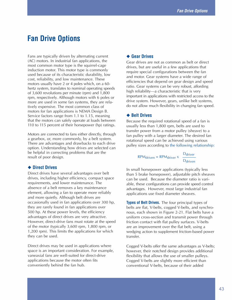
Fan Drive Options
Fans are typically driven by alternating current(AC) motors. In industrial fan applications, themost common motor type is the squirrel-cageinduction motor. This motor type is commonlyused because of its characteristic durability, lowcost, reliability, and low maintenance. Thesemotors usually have 2 or 4 poles which, on a 60-hertz system, translates to nominal operating speedsof 3,600 revolutions per minute (rpm) and 1,800rpm, respectively. Although motors with 6 poles ormore are used in some fan systems, they are rela-tively expensive. The most common class ofmotors for fan applications is NEMA Design B.Service factors range from 1.1 to 1.15, meaningthat the motors can safely operate at loads between110 to 115 percent of their horsepower (hp) ratings.
Motors are connected to fans either directly, througha gearbox, or, more commonly, by a belt system.There are advantages and drawbacks to each driveoption. Understanding how drives are selected canbe helpful in correcting problems that are theresult of poor design.
◆ Direct DrivesDirect drives have several advantages over beltdrives, including higher efficiency, compact spacerequirements, and lower maintenance. Theabsence of a belt removes a key maintenance element, allowing a fan to operate more reliablyand more quietly. Although belt drives are occasionally used in fan applications over 300 hp,they are rarely found in fan applications over 500 hp. At these power levels, the efficiencyadvantages of direct drives are very attractive.However, direct-drive fans must rotate at the speedof the motor (typically 3,600 rpm, 1,800 rpm, or1,200 rpm). This limits the applications for whichthey can be used.
Direct drives may be used in applications wherespace is an important consideration. For example,vaneaxial fans are well-suited for direct-driveapplications because the motor often fits conveniently behind the fan hub.
◆ Gear DrivesGear drives are not as common as belt or directdrives, but are useful in a few applications thatrequire special configurations between the fan and motor. Gear systems have a wide range of efficiencies that depend on gear design and speedratio. Gear systems can be very robust, affordinghigh reliability—a characteristic that is very important in applications with restricted access to thedrive system. However, gears, unlike belt systems,do not allow much flexibility in changing fan speed.
◆ Belt DrivesBecause the required rotational speed of a fan is usually less than 1,800 rpm, belts are used to transfer power from a motor pulley (sheave) to afan pulley with a larger diameter. The desired fanrotational speed can be achieved using variouspulley sizes according to the following relationship:
In small horsepower applications (typically lessthan 5 brake horsepower), adjustable pitch sheavescan be used. Because the diameter ratio is vari-able, these configurations can provide speed controladvantages. However, most large industrial fanapplications use fixed diameter sheaves.
Types of Belt Drives. The four principal types ofbelts are flat, V-belts, cogged V-belts, and synchro-nous, each shown in Figure 2-21. Flat belts have auniform cross-section and transmit power throughfriction contact with flat pulley surfaces. V-beltsare an improvement over the flat belt, using awedging action to supplement friction-based powertransfer.
Cogged V-belts offer the same advantages as V-belts;however, their notched design provides additionalflexibility that allows the use of smaller pulleys.Cogged V-belts are slightly more efficient thanconventional V-belts, because of their added
Fan Drive Options
DdriverRPMdriven = RPMdriver x
Ddriven
43

Improving Fan System Performance
Fan Drive Options
flexibility and the fact that the notched surfacetransfers force more effectively.
Synchronous belts offer many advantages overstandard flat belts and V-belts. By using a meshengagement, synchronous belts are the most efficient type of belt drive because they do not suffer efficiency losses through slip. Synchronousbelts have teeth that engage with grooves in thesheave. Synchronous belts can allow lower belttension than conventional belts, reducing the radialloads on motor and fan bearings and extendingtheir operating lives. Further, synchronous belts donot lose efficiency as they wear.
Despite their advantages, synchronous belts must be used with caution. Synchronous belts are very noisy, which often discourages their use.Synchronous belts transfer torque very quicklyand, in applications with rapid load changes, thecumulative effects of sudden acceleration anddeceleration increases wear on the driven machineryand the risk of catastrophic failure. Synchronousbelts also require precise alignment, which is diffi-cult to achieve in some fan applications. Beforeselecting or switching to synchronous drives, oneshould contact the belt drive vendor and reviewthe history of similar equipment in similar serviceconditions.
Belt Sizing Considerations. The required belt capacity must not only include the horsepowerrequired by the driven load; it must also accountfor site-specific factors, such as temperature,
service factor, and arc of contact. The effect of temperature varies according to the belt material.Rubber contracts at higher temperatures.Consequently, in belts that have high rubber content, tension and stress increase as the drivesystem temperature increases. Because temperaturealso affects the mechanical strength of a belt, beltsshould be sized to meet the torque requirements atthe highest normal operating temperature.
Ignoring the belt service factor and arc of contact(see Table 2-1) can lead to undersizing the belts,which may lead to frequent servicing or belt failure.The belt service factor accounts for accelerationloads during start-up and under load changes. Formost fans, the belt service factor is between 1.2and 1.4. The arc of contact correction factoraccounts for the loss in power that results whenthe belt runs over by less than 180° of the pulley circumference. As shown in Table 2-1, the horse-power rating drops off as the arc of contactdecreases. In applications where a small arc ofcontact is unavoidable, the use of cogged V-beltsis recommended.
Belt Speed. The sensitivity of fan power to speedmakes belt-drive sizing an important issue.Although flow rate is linearly related to fan speed,power is related to the cube of fan speed. Evenchanges in the slip of an induction motor can create noticeable changes in the power transferredto the airstream. Consequently, establishing the rightfan speed is critical to operating the system efficiently.In general, fan-belt speed should not exceed
Figure 2-21. Different Types of Belts
Flat Belt V-Belt Cogged V-Belt Synchronous Belt Mesh Contact
44

Fan Drive Options
6,500 feet per minute (ft./min.). Many manufacturerssuggest that to minimize bearing loads and toincrease reliability, up to but no more than 6,500 ft./min is a good speed value for belt systemdesign.
Maintenance Practices. Belt tension and alignmentshould be checked periodically (see Figure 2-22).Proper belt tension is typically the lowest that prevents a belt from slipping at peak load. Animportant maintenance practice to avoid is the useof belt dressing. Belt dressing is a surface treatmentthat increases the level of friction between a beltand pulley. Because it masks the fundamentalcause of slippage, belt dressing only provides a
temporary means of reducing noise. Belt slippageshould be corrected by either cleaning the drivesystem or adjusting belt tension.
When installing or replacing belts, ensure they areoriented correctly in accordance with the directionsof the manufacturer. Belts are often tagged to showthe preferred direction of rotation. Although somebelts can be operated in either direction, belt manufacturers often test their belts in one directionand package them with an indication of this direction.
In high-temperature applications, new belts shouldbe operated under low-load conditions and at normal
Table 2-1. Effect of Arc of Contact on V-Belt Horsepower Rating
Arc of contact
Figure 2-22. Proper Belt Tension
IncorrectCorrect
Rotation
RotationLoose belt indicated by excessiveslack on the drive side
Reasonable slack on thenon-drive side of the belt
Correction factor forhorsepower rating for a V-belt
according to arc of contact180° 1170° .98160° .95150° .92140° .89130° .86120° .83110° .79100° .7490° .69
45

Improving Fan System Performance
Fan Drive Options
operating temperature for a reasonable period. Thisrun-in time increases the creep strength of the belt.
Maximum Practical Speed Ratio. Most industrial fan-belt drive applications are limited to speed ratiosbelow 4:1 (the motor speed is 4 times faster thatthe fan speed); however, for small horsepowerapplications (less than 1 hp), this ratio can be ashigh as 10:1. The limiting factors on speed ratiosare the practical size of the pulleys, the arc of con-tact between the belt and the drive pulley, and beltspeed.
Alignment. Proper belt installation requires carefulalignment and tensioning to ensure that belts wearcorrectly. Belt alignment is important to minimizeside wear on the belt and to keep the stress on thebelt distributed evenly (see Figure 2-23). Side wearon a belt will shorten its life; insufficient tensionpromotes belt slippage, which can “polish” thesheave surface as well as the contact surface of thebelt. A polished sheave surface has a low frictionconstant, which reduces the belt’s ability to transferpower. This loss is especially problematic after abelt stretches, releasing tension and decreasing theforce holding the belt against the sheave.
◆ Other ConsiderationsService conditions, such as high-temperature, contaminants, erosive or corrosive properties, andmoisture, can preclude the exposure of motors tothe airstream. Motors can be sealed for protectionagainst the harmful effects of some airstreams;however, these motors are more expensive andsometimes require external cooling services.
Motor performance is closely linked to operatingtemperature and, in high-temperature applications,less heat from the motor windings is rejected tothe ambient air. High winding temperaturesdecrease motor efficiency and accelerate thedegradation of winding insulation, shorteningmotor life. In most severe system environments,belt drives are used to allow the motor to operateoutside of the harmful service conditions.
Access. Access to a motor for maintenance andrepairs in a direct-drive fan assembly can also beproblematic. Because many direct-drive applications are selected for space-saving reasons,these motors are often located in tight spaces,complicating tasks such as lubricating and replacingbearings.
Figure 2-23. Improper Alignment
To avoid side wear and to evenly load a belt,minimize these types of misalignments.
46

Multiple-Fan Arrangements
◆ Basic PrincipleFans can be combined in series or in parallel as analternative to using single, large fans. In manycases, two smaller fans are less expensive andoffer better performance than one relatively largeone. Fans configured in series tend to be appropriatefor systems that have long ducts or large pressuredrops across system components. Fans used in aninduced-draft/forced-draft configuration can minimize the amount of pressurization in a duct oran enclosure. Advantages of fans in series include:
■ Lower average duct pressure■ Lower noise generation■ Lower structural and electrical support
requirements.
Fans placed in parallel can provide several advantages including:
■ High efficiencies across wide variations insystem demand
■ Redundancy to mitigate the risk of downtimebecause of failure or unexpected maintenance.
Parallel configurations may be feasible for systemswith large changes in air-moving requirements.Wide variations in system demand preclude a single fan from consistently operating close to itsbest efficiency point (BEP). Operating a fan awayfrom its BEP can result in higher operating andmaintenance costs. Multiple fans placed in parallelallow units to be energized incrementally to meetthe demands of the system. By energizing or de-energizing individual fans to meet demandchanges, each fan can be operated more efficiently.To allow operation of individual fans in a multiple-fan arrangement, each fan must have a back-draftdamper installed to prevent recirculation throughthe fan when it is idle.
Parallel fan configurations may also be a safetyrequirement in case of a single fan failure. In mining and other hazardous work environments,ventilation is critical to worker safety. The
existence of backup fans can help avoid productionstoppages and may be a safety requirement.
◆ Advantages of Multiple-Fan ArrangementsLower Average Duct Pressure. As shown in Figure 2-24, the series-configurations fans alongdifferent points in a system minimize the averagestatic pressure in a duct. Because leakage in a ductsystem depends largely on the pressure differencebetween inside and outside the system, reducingthe maximum system pressure can minimize energylosses attributable to system leaks.
Lower Noise Generation. Lower pressure requirements can decrease the noise generated byfan operation.
Redundancy. Failure of one unit does not force asystem shutdown. In a single-fan application, arepair task on that fan requires a system shutdown.With a multiple-fan arrangement, one can berepaired while the others serve the system. In somefacilities, fan failure can cause the interruption ofproduction work. With redundant fan configurations,failure of one fan does not necessarily cause thewhole process to halt. Although total fan outputfalls if one of the parallel units fails, the capacityof the remaining fan or fans may be sufficient forlimited production.
Efficiency. Allowing each fan to operate close to itsBEP can provide substantial energy savings. Inaddition, a potential advantage of multiple fans isa higher overall efficiency level. Although largermotors tend to be more efficient than smaller ones,operating smaller, higher-speed fans close to theirBEPs can often achieve a net efficiency advantageover a single, low-speed fan.
Structural and Electrical Constraints. Two smallerfans in series may be more suitable in terms ofstructural and electrical requirements than a singleone. Large motors have large starting currents thatcan affect the power supply to other parts of thefacility. This concern is particularly acute if theservice requires the fan to energize and de-energize
Multiple-Fan Arrangements
47

Improving Fan System Performance
Multiple-Fan Arrangements
relatively often. Frequent power surges that oftenaccompany the start-up of large motors can createpower quality variations that are problematic fornumeric controlled machinery and other sensitiveequipment.
Also, the use of multiple fans in parallel may benecessary because of space considerations. A sin-gle fan with an impeller large enough to move theproper amount of air may not fit into the availablespace or may encounter structural constraints.
◆ Potential Disadvantages of Multiple-FanArrangements
When placing centrifugal fans in parallel, cautionshould be used to ensure that one fan does not dominate another. Ideally, all fans should be thesame type and size; however, differences in theduct configuration can cause one fan to operate
against a higher backpressure. In severe cases, onefan will force another fan to operate far away fromits BEP. Often, fans placed in parallel are the samemodel so that there is balanced load sharing during periods when all the fans are operating.
Another problem that accompanies parallel operation of fans is instability. This problem isespecially applicable to fans with unstable operatingregions (axial fans, forward-curved centrifugal fans,and airfoil fans). Instability results from alternateload sharing that can occur below certain airflowrates, as shown by the shaded region in Figure 2-25.This can occur despite the fact that each fan aloneis operating outside of its stall region.
However, the combined performance curve ofboth fans has a region in which there are multiplecombinations of airflow from each fan that can
Figure 2-24. Lower Duct Pressure Because of Fans Placed in Series
Average Pressure
System Resistance
System Resistance
Airflow
Airflow
Peak Pressure
Average Pressure
Peak Pressure
Distance Along Duct
Distance Along Duct
System Resistance
Pres
sure
Pres
sure
Two Fans in Series
Single Fan
48
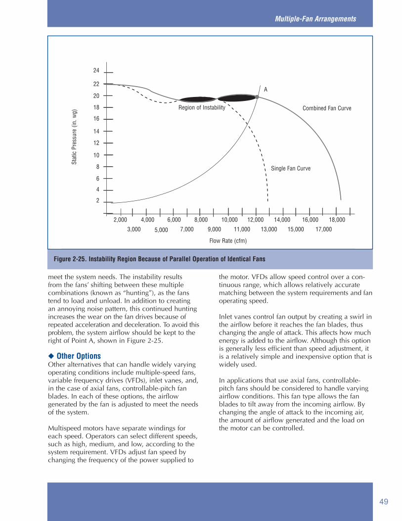
Multiple-Fan Arrangements
meet the system needs. The instability results from the fans’ shifting between these multiple combinations (known as “hunting”), as the fanstend to load and unload. In addition to creating an annoying noise pattern, this continued huntingincreases the wear on the fan drives because ofrepeated acceleration and deceleration. To avoid thisproblem, the system airflow should be kept to theright of Point A, shown in Figure 2-25.
◆ Other OptionsOther alternatives that can handle widely varyingoperating conditions include multiple-speed fans,variable frequency drives (VFDs), inlet vanes, and,in the case of axial fans, controllable-pitch fanblades. In each of these options, the airflow generated by the fan is adjusted to meet the needsof the system.
Multispeed motors have separate windings foreach speed. Operators can select different speeds,such as high, medium, and low, according to thesystem requirement. VFDs adjust fan speed bychanging the frequency of the power supplied to
the motor. VFDs allow speed control over a con-tinuous range, which allows relatively accurate matching between the system requirements and fan operating speed.
Inlet vanes control fan output by creating a swirl in the airflow before it reaches the fan blades, thus changing the angle of attack. This affects how much energy is added to the airflow. Although this option is generally less efficient than speed adjustment, it is a relatively simple and inexpensive option that is widely used.
In applications that use axial fans, controllable-pitch fans should be considered to handle varying airflow conditions. This fan type allows the fan blades to tilt away from the incoming airflow. By changing the angle of attack to the incoming air, the amount of airflow generated and the load on the motor can be controlled.
Figure 2-25. Instability Region Because of Parallel Operation of Identical Fans
Region of Instability
Stat
ic P
ress
ure
(in. w
g)
Single Fan Curve
Flow Rate (cfm)
A
2
4
6
8
10
12
14
16
18
20
22
24
2,000 4,000 6,000 8,000 10,000 12,000 14,000 16,000 18,000
17,00015,00013,00011,0009,0007,0005,0003,000
Combined Fan Curve
49

Fan systems are often critical in supporting plantoperations. A significant portion of all energy con-sumed by motor-driven equipment in manufactur-ing facilities is for process fans and air distribution.In many industrial applications, fans help maintainenvironmental conditions that ensure worker safetyand productivity by keeping machinery spaces cool.Because they often directly support productionprocesses, many fans operate continuously. Theselong run times translate into significant energyconsumption and substantial annual operatingcosts.
The operating costs of large fans are often highenough that improving fan system efficiency canoffer a quick payback. In spite of this, facility person-nel often do not know the annual operating costsof an industrial fan, or how much money theycould save by improving fan system performance.
Fan system operating costs primarily include electricity and maintenance costs. Of these twocomponents, electricity costs can be determinedwith simple measurements. In contrast, maintenancecosts are highly dependent on service conditionsand need to be evaluated case-by-case. Aparticularly useful method of estimating these costsis to review the maintenance histories of similarequipment in similar applications.
◆ Load FactorFan economic analyses are primarily affected bythe amount of time and the percentage of fullcapacity at which a fan operates. Because the fanusually does not operate at rated full load all thetime, an estimate of its average load factor—theaverage percentage of full load that a fan operatesover a period of time—must be made. Unfortunately,unless operators maintain comprehensive recordsor are highly familiar with fan operating data, theaverage load factor may be difficult to determine.
A more accurate analysis of equipment operationis the load-duty cycle. Load-duty cycle refers to theamount of time that equipment operates at variousloads relative to its rated capacity and is often usedduring the system design process. An example of aload-duty cycle is shown in Figure 2-26. Load factor can be determined from the load-duty cycle.
◆ Calculating Electricity ConsumptionElectricity consumption can be determined by several methods, including:
■ Direct measurement of motor current or power■ Use of motor nameplate data■ Use of performance curve data.
With any of these methods, the data’s usefulness islimited by how representative it is of the averagesystem operating conditions.
Fan System Economics
Fan System Economics
Figure 2-26. Load-Duty Cycle
100
80
60
40
20
00 20 40
Percent of Full Load
Perc
ent o
f Ope
ratin
g Ho
urs
60 80 100
50

Improving Fan System Performance
In systems with widely varying operating conditions,simply taking data once will probably not providea true indication of fan energy consumption.
Nameplate Data. A quick way to determine energycosts is to use the fan motor nameplate data. Inmany applications, the fan/motor assembly is oversized, which means the motor operates wellbelow its full-load nameplate data. However, byusing the nameplate data in combination with loadfactor and power factor estimates, the fan’s annualoperating costs can be calculated. Other necessarydata include the annual hours of operation(hours/year) and the average annual unit cost ofelectricity ($/kilowatt-hour [kWh]).
Annual electricity costs can be calculated byinserting this information into the equation foundin the Simple Calculation sidebar. This equationassumes the electric motor driving the fan is 95 percent efficient (the 0.95 in the 1/0.95 factor),which is a reasonable estimate for a fan motorlarger than 50 horsepower (hp). Newer motorsmay have even higher efficiencies, thanks to theEnergy Policy Act, which has been in effect sinceOctober 1997. If the fan uses an older motor thathas been rewound several times or has a smallermotor, then a lower motor efficiency should beused.
The motors used on most fans have a 1.15 contin-uous service factor. This means that a motor with anominal nameplate rating of 100 brake horsepower(bhp) may be operated continuously up to 115 bhp,although motor efficiency drops slightly above therated load. Using nameplate data to calculateenergy costs on motors that operate above theirrated loads will understate actual costs.
Direct Measurement. A more accurate way to determine electricity consumption requires takingelectrical measurements of both full-load ampsand volts. Motor full-load bhp and efficiency arenot required for this calculation. However, thepower factor over a range of operating conditions isrequired. If practical, the power factor should bemeasured with a power meter; however, if thismeasurement is not feasible, then it can beobtained from the motor manufacturer.
Using a clamp-type ammeter, the current on eachof the three power cables running to the motorshould be measured. The average of these threereadings should be used as the current value. Thisis also an opportunity to determine if there arephase imbalances.
Sometimes the motor controller is a convenientpoint to take these readings while, at other sites, theconnection box on the motor itself is more accessi-ble. Line voltage is usually measured at the motorcontroller and should be measured around thesame time as the current reading. In some facilities,line voltage drops with increased power usage.
Wattmeters, in general, are more difficult to usebecause they require two simultaneous inputs,voltage and current; many motor installations donot offer convenient access to both. However, ifthe use of a wattmeter is practical, then it wouldprovide a more accurate indication of actualpower consumption. Wattmeters provide a directreading of real power, obviating the need to estimate power factor. Note that the direct measurement of motor current is not always practical. “Hot” measurement of motor voltageexposes workers to risk and may not be feasible in some industrial environments because of expo-sure of the power connections to moisture or contaminants. Such readings should only be takenby properly trained personnel.
Fan System Economics
Simple CalculationAnnual electricity costs =(motor full-load bhp) x (0.746 kW/hp) x(1/efficiency) x (annual hours of operation) x (electricitycost in $/kWh) x (load factor)
Assumptions:• Cost of electricity = $0.05/kWh• Load factor = 65 percent• Motor efficiency = 95 percent
For example:• Motor full-load bhp = 100 hp• Annual hours of operation = 8,760 hours (3-shift,
continuous operation)
Annual electricity costs = (100 hp) x (0.746 kW/hp) x (1/0.95) x (8,760 hours)x ($0.05/kWh) x (0.65) = $22,356
51

The Direct Measurement sidebar shows an exam-ple calculation of energy costs. By taking full-loadamps and volts, converting them to full-load kilowatt (kW), multiplying by hours of operationand electricity price, annual energy costs can bedetermined.
Use of Fan Curves. Another method of determiningfan power consumption is to take pressure measurements of the airstream and use the fan’sperformance curve to determine the correspondingbhp. Refer to Figure 2-27. The correct method ofmeasuring fan pressure depends on how the fan isconfigured in the system.
Figure 2-28 shows different methods of measuringfan pressure. Once the fan operating pressure isknown, the corresponding horsepower reading canbe found. The Calculation with Fan Curves sidebarshows how to estimate annual energy cost.
◆ Energy and Demand Charges—Understanding Your Electricity Bill
The calculations shown previously use electricityrates that are stated in terms of average dollars perkWh ($/kWh). However, electric utilities bill industrial customers using more complicated ratestructures. These typically include both energy($/kWh) and demand charges ($/kW), and havedifferent rates depending on the level of consumption or seasons. Demand charges are
Fan System Economics
Calculation with Fan CurvesAnnual electricity costs =Fan bhp/motor efficiency x (annual hours of operation)x (electricity cost in $/kWh) x (load factor)
Assumptions:• Fan discharge pressure is known• Motor efficiency = 90 percent• Load factor = 65 percent• $0.05/kWh unit electricity cost
For example:• Fan discharge pressure = 19 in. wg• Reading from the bhp line, fan bhp = 49
Annual electricity costs = (49 bhp) x (0.746 kW/hp) x (1/0.9) x (8,760 hours)x ($0.05/kWh) x (0.65) = $11,563
Direct Measurement CalculationCase I. Separately using a voltmeter and an ammeterAnnual electricity costs =(full-load amps) x (volts) x (1.732) x (power factor) ÷(1000)x (annual hours of operation) x (electricity cost in$/kWh) x (load factor)
Case II. Use of a WattmeterAnnual electricity costs =Wattmeter reading (using a 3-phase setting) x (annualhours of operation) x (electricity cost in $/kWh) x (loadfactor)
Assumptions:• Cost of electricity = $0.05/kWh• Load factor = 65 percent• Motor efficiency = 95 percent• Power factor = 0.85
For example:• Full-load amps = 115 amps• Voltage = 460 volts• Annual hours of operation = 8,760 hours (3-shift,
continuous operation)
Annual electricity costs = (115 amps) x (460 volts) x (1.732) x (0.85)÷(1000) x(8,760 hours) x ($0.05/kWh) x (0.65) = $22,172
Figure 2-27. Use of Fan Curve to Determine Power Consumption
BHP
10
20
30
40
50
60
Power Curve
Fan Curve
Stat
ic P
ress
ure
(in w
g)
2468
101214161820222426
2,0004,000
6,000 10,000 14,000 18,0008,000 16,000
Flow Rate (CFM)
12,000
bhp
Flow Rate (cfm)
Stat
ic P
ress
ure
(in. w
g)
52

Improving Fan System Performance
based on the peak demand for a given month orseason and can have significant impacts on electricity costs for some customers. When the economic impacts of efficiency measures are calculated, the actual cost of the electricity needs tobe considered, taking into account energy anddemand charges, seasonal rates, and different ratesfor different levels of consumption.
◆ Maintenance Considerations andLife-Cycle Costs
In addition to the cost of energy consumption,maintenance costs can be a significant portion of afan system’s total operating costs. There are twoprincipal types of maintenance: preventive andpredictive. Both are intended to improve systemreliability, reduce the risk of unplanned downtime,and avoid expensive failures. Preventive mainte-nance generally refers to the use of a schedule toperform inspections and replacement tasks.Predictive maintenance uses diagnostic tools toevaluate machinery condition, allowing effectiveplanning of repair or replacement tasks.
In much the same way that preventive and predictivemaintenance schedules minimize expensiverepairs, a well-designed system can avoid higher-than-necessary operating costs. Using a life-cyclecost perspective during initial system design orduring the planning of system upgrades and modifications can provide both lower operatingcosts and improved system reliability. For fanapplications, the dominant components of life-cycle cost include initial equipment cost, energyconsumption, maintenance, and decommissioning.A highly efficient fan system is not merely a systemwith an energy-efficient motor. Overall system efficiency is the key to maximum cost savings.Often, users are only concerned with initial cost,accepting the lowest bid for a component, whileignoring system efficiency. To achieve optimumfan system economics, users should select equip-ment based on life-cycle economics and operateand maintain the equipment for peak performance.
Fan System Economics
Figure 2-28. Alternative Methods of Measuring Fan Pressure
Inlet Total Pressure
Ducted Inlet and Outlet
Free Inlet – Ducted Outlet Ducted Inlet – Free Outlet
Fan Total Pressure Outlet Total Pressure
StaticPressure
TotalPressure
TotalPressure
StaticPressure
53

This appendix is a collection of terms used in fans and fan systems. It is based primarily onEngineering Letter G, written by The New YorkBlower Company, and is used here with permission.
acceleration loss—the energy required to induceair to move at the entry to a system
acfm—actual cubic feet per minute; the quantityor volume of a gas flowing at any point in a sys-tem. Fans are rated and selected on the basis ofACFM, as a fan handles the same volume of airregardless of density.
air conditioning—treating air to meet the require-ments of a conditioned space by controlling itstemperature, humidity, cleanliness, and distribu-tion.
air curtain—mechanical air-moving devicedesigned to limit the influx of unwanted air at abuilding opening
air handling unit—factory-made encased assemblyconsisting of a fan or fans and other equipment tocirculate, clean, heat, cool, humidify, dehumidify,or mix air
ambient—immediate surroundings or vicinity
AMCA—Air Movement and Control AssociationInternational, Inc.
anemometer—a device that reads air velocity, suchas a wind vane. In fan applications, it is usually a spinning-vane-type instrument used toread low velocities at registers or grills.
anneal—the process of relieving stress and brittle-ness in metals by controlled heating and cooling
ANSI—American National Standards Institute
API—American Petroleum Institute
ARI—Air Conditioning and Refrigeration Institute
ASHRAE—American Society of Heating,Refrigerating, and Air Conditioning Engineers
ASME—American Society of Mechanical Engineers
aspect ratio—the ratio of width to length
ASTM—American Society for Testing and Materials
atmospheric pressure—one atmosphere is approximately 14.7 psi, 408” water gauge at sealevel. Airflow is the result of a difference in pressure(above or below atmospheric) between two points.
attenuation—absorption of sound pressure.Attenuation reduces the amplitude of a sound wavewhile leaving the frequency unchanged.
axial fan—fan where the airflow through theimpeller is predominantly parallel to the axis ofrotation. The impeller is contained in a cylindricalhousing.
axial flow—in-line air movement parallel to thefan or motor shaft
backdraft damper—damper used in a system torelieve air pressure in one direction and to preventairflow in the opposite direction
backward-inclined fan—a group of centrifugal fanswith blades that angle back from the direction offan rotation. These fans can have curved and air-foil blade shapes. Airfoil blades are among themost efficient fan types.
balancing—the process of adding (or removing)weight on a rotor in order to move the center ofgravity toward the axis of rotation
barometric pressure—a measurement of the pressure of the atmosphere; standard atmosphericpressure is 29.92” Hg at sea level
Fan System Terminology
Fan System Terminology
54

Improving Fan System Performance
bearing losses—power losses resulting from frictionin the main bearings
Bernoulli’s Theorem—the principle that the totalenergy per unit of mass in the streamline flow of amoving fluid is constant, being the sum of thepotential energy, the kinetic energy, and the energybecause of pressure. In terms of air movement, the theorem states that static pressure plus velocitypressure as measured at a point upstream in thedirection of airflow is equal to the static pressureplus velocity pressure as measured at a pointdownstream in the direction of airflow plus the friction and dynamic losses between the points.
best efficiency point (BEP)—the operating conditionat which a fan transfers energy to an airstream mostefficiently. In general, this is a point on a fan curveto the right of peak pressure.
blade liners—pieces of material added over theimpeller blades to reduce abrasion of the blades
blade-pass frequency—the tone generated by theblades passing a fixed object
blast area—the fan outlet area less the projectedarea of the cut-off
brake horsepower (bhp)—a measure of the rate ofenergy expended. One bhp is equivalent to mechan-ical energy consumed at a rate of 33,000-ft. lbs.per minute.
breakdown torque—maximum torque a motor willproduce without a sudden decrease in speed. Oftenreferred to as pullout torque or maximum torque.
Btu—British thermal unit; heat required to raise thetemperature of 1 pound of water by 1°F
capture velocity—air velocity necessary to over-come opposing air currents or natural flow andcause contaminated air, fumes, or material to flowin a desired direction
Celsius—a thermometric scale in which waterboils at 100° and freezes at 0°
centrifugal fan—a fan design in which air is discharged perpendicular to the impeller’s rotational axis
cfm—cubic feet per minute; the volume of flow fora given fan or system
coatings—specialty coverings, typically referred toas paints, with varying degrees of resistance toatmospheric or chemical corrosion
coefficient of conductivity—the rate of heat transferthrough a material, expressed in Btu, transmittedper hour through one square foot of surface perdegree difference in temperature across the material.
compressibility—a factor used by fan manufacturersto correct performance ratings in higher pressureranges to account for the fact that air is a compressible gas
compression—a phenomenon related to positivepressure. When air is forced into a system it iscompressed and becomes more dense. Depending onthe volume or weight of air required downstreamin the positive-pressure portion of the system, thevolume of air at the inlet of a fan may have to beadjusted by the ratio of absolute pressure at theentrance of the fan versus the design requirementsin the system.
conveying velocity—the air velocity required in aduct system to maintain entrainment of a specificmaterial
corrosion—the deterioration of a material bychemical or electrochemical reaction resultingfrom exposure to weathering, moisture, chemical,or other agents in the environment in which it isplaced
curve, fan performance—a graphic representationof static or total pressure and fan bhp requirementsover an airflow volume range
curve, system—a graphic representation of thepressure versus flow characteristics of a given system
damper—an accessory to be installed at the faninlet or outlet for air-volume modulation
density—the measure of unit mass equal to itsweight divided by its volume (lbs./ft.3); standard airis 0.075 lbs./ft.3
Fan System Terminology
55

dew point—the temperature at which condensationbegins to form as air is cooled
dust—air suspension of particles [aerosol] of anysolid material, usually with a particle size smallerthan 100 micrometers
dust collector—an air-cleaning device used toremove heavy-particulate loadings from exhaustsystems prior to discharge
DWDI—double-width, double-inlet fans
dynamic balance—the mechanical balancing of arotating part or assembly in motion
efficiency, mechanical total—the ratio of fan out-put to the power applied to the fan; can be helpfulin selecting fan size, type, or manufacturer for thesame application
elevation—the distance of the subject site above orbelow sea level
entry loss—the loss in pressure caused by air flowing into a system; normally expressed in fractions of velocity pressure
equivalent duct diameter—for rectangular ductwith sides a and b is:
evase—a diffuser at the fan outlet that graduallyincreases in area to decrease velocity and to convert kinetic energy to static pressure at the fanoutlet and inlet
Fahrenheit—a thermometric scale in which waterboils at 212°F and freezes at 32°F
fan—a power-driven machine that moves a continuous volume of air by converting rotationalmechanical energy to an increase in the total pressure of the moving air
fan capacity—performance requirement for whicha fan is selected to meet specific system calculationsgiven in terms of ACFM at the fan inlet
fan class—operating limits at which a fan must bephysically capable of operating safely
fan laws—theoretical constant relationshipsbetween cfm, rpm, static pressure (sp), and bhp fora given fan used in a given fixed system:
cfm ~ rpmsp ~ (rpm)2
bhp ~ (rpm)3
foot-pound (ft.-lb.)—torque rating or requirement;equivalent to the force required to move a 1-pound weight 1 foot in distance, equal to12 in.-lb.
forced draft—how air is provided in a process,such as a combustion process; when air is blownor forced into a process, it is known as a “forceddraft” system. Also see Induced Draft.
forward-curved blade fan—a fan type with bladesthat angle toward the direction of rotation. This fantype generates relatively high pressure at low operating speeds and is used frequently in residentialfurnace applications
fpm—feet per minute; commonly defines air veloc-ity (to determine velocity pressure or suitability formaterial conveying), shaft/bearing speeds (used todetermine lubrication requirements), and impellertip speeds
frame size—a set of physical dimensions of motorsas established by National Electrical ManufacturersAssociation (NEMA) for interchangeability betweenmanufacturers. Dimensions include shaft diameter,shaft height, and motor-mounting footprint.
frequency—any cyclic event, whether vibration,alternating current, or rotational speed. Usuallyexpressed in cycles per second (cps) or just “cycles.”
friction loss—resistance to airflow through anyduct or fitting, given in terms of static pressure
FRP—abbreviation for fiberglass-reinforced-plastic
full-load speed—the speed at which the ratedhorsepower is developed. This speed is less thansynchronous speed and varies with motor type andmanufacturer.
Fan System Terminology
4abDeff = √ π
56
Improving Fan System Performance
full-load torque—the torque required to producethe rated horsepower at full-load speed
fumes—airborne particles, usually less than 1 micrometer in size, formed by condensation ofvapors, sublimation, distillation, or chemical reaction
gauge (gage)—metal manufacturers’ standardmeasure of thickness for sheet stock
gauge pressure—the pressure differential betweenatmospheric and that measured in the system
heat exchanger—a device, such as a coil or radiator, which is used to transfer heat betweentwo physically separated fluids
HEPA filter—high-efficiency particulate air filters,commonly called absolute filters
hertz—frequency measured in cycles per second
Hg—symbol for mercury. Pressure is often measuredin inches of mercury (1 inch Hg = 13.64 incheswg).
horsepower (hp)—(as applied to motors) an indexof the amount of work the machine can perform ina period of time. One hp equals 33,000-ft. lbs. ofwork per minute, also equal to 0.746 kilowatts.Horsepower can be calculated by:
housing—the casing or shroud of a centrifugal fan
HVAC—heating, ventilating, and air conditioning
impeller—another term for fan “wheel.” The rotating portion of the fan designed to increase theenergy level of the gas stream.
impeller diameter—the maximum diameter measured over the impeller blades
impingement—striking or impacting, such as material impingement on a fan impeller
inch of water—unit of pressure equal to the pressure exerted by a column of water 1 inch highat a standard density (1 inch of water = 0.036 psig)
inch-pound (in.-lb.)—torque equal to one-twelfthfoot-pound
inclined manometer—a metering device used toobtain pressure measurements
induced draft—how air is provided in a process,such as a combustion process, where air is drawnor pulled through a process. Also see forced draft.
induction—the production of an electric current ina conductor in a changing magnetic field
inertia—tendency of an object to remain in thestate it is in. Also see WR2.
inlet-vane damper—round multiblade dampermounted to the inlet of a fan to vary the airflow
instability—the point of operation at which a fan orsystem will “hunt” or pulse; common in forward-curved fans and some axial fan types where thepoint of operation is left of the peak of the static-pressure curve
kilowatt—measure of power equal to 1.34 horse-power
L-10 bearing life—the theoretical number of hoursafter which 90 percent of the bearings subjected toa given set of conditions will still be in operation
laminar flow—gas or fluid in parallel layers withsome sliding motion between the layers, characteristicof airstreams with Reynolds numbers less than 2,000
load factor—ratio of the average capacity to therated full capacity, determined by the followingrelationship:
louver—a device composed of multiple bladeswhich, when mounted in an opening, permits theflow of air but inhibits the entrance of undesirableelements
Fan System Terminology
Torque x RPMhorsepower =
5,250
Load ∑ (Actual Load x Number of operating hours at this load)
Factor=
Rated Full Load x Number of hours in the period
57

make-up air—a ventilating term which refers to thereplacement of air lost because of exhaust airrequirements
manometer—instrument for measuring pressure; u-shaped, and partially filled with liquid, eitherwater, light oil, or mercury
maximum continuous rating—the point at whichthe fan is expected to operate
natural frequency—the frequency at which a com-ponent or system resonates
NEMA—the National Electrical ManufacturersAssociation; the trade association establishing standards of dimensions, ratings, enclosures, insulation, and other design criteria for electricmotors and other devices
noise criteria—a way for a designer to specify themaximum permissible sound-power level in eachof the eight-octave bands. Noise criteria curves givemaximum permissible intensity per octave-band ina graphical form.
opposed-blade damper—a type of damper whereadjacent blades rotate in the opposite direction
parallel-blade damper—a type of damper wherethe blades rotate in the same direction
parallel fans—two or more fans that draw air from acommon source and exhaust into a common ductor plenum. A parallel fan arrangement is generallyused to meet volume requirements beyond that ofsingle fans. Two identical fans in parallel willeffectively deliver twice the rated flow of any onefan at the same static pressure.
pitch diameter—the mean diameter or point atwhich V-belts ride within a sheave. This dimensionis necessary for accurate drive calculations.
pitot tube—a metering device consisting of a double-walled tube with a short right-angle bend; theperiphery of the tube has several holes through whichstatic pressure is measured; the bent end of the tubehas a hole through which total pressure is measuredwhen pointed upstream in a moving gas stream
plenum—a chamber or enclosure within an air-handling system in which two or more branchesconverge or where system components such asfans, coils, filters, or dampers are located
poles—the number of magnetic poles establishedinside an electric motor by the placement andconnection of the windings
propeller fan—an axial fan type that is compact,inexpensive, but relatively inefficient
psia—pounds per square inch absolute, representstotal pressure above a perfect vacuum
psig—pounds per square inch measured in gaugepressure, represents the difference between psiaand atmospheric pressure
radial blade—fan impeller design with blades posi-tioned in straight radial direction from the hub
radial-tip fan—a fan type with short blades andlarge clearances between the blades and theimpeller hub
rarefication—a phenomenon related to negativepressure. When air is drawn through resistanceinto a fan inlet, the air is stretched out, or rarefied,and becomes less dense than at the entry to thesystem. While negligible at low pressures and volumes, high-pressure fan selection must bebased on rarefied inlet density.
relative humidity—the ratio of existing water vaporto that of saturated air at the same dry-bulb tempera-ture
Reynolds number—a mathematical factor used toexpress the relation between velocity, viscosity,density, and dimensions in a system of flow; usedto define fan proportionality
rotor—the rotating part of most alternating currentmotors
rpm—revolutions per minute
radial tip—fan impeller design with shallow bladesin which the trailing edge points radially from theaxis of rotation
Fan System Terminology
58

Improving Fan System Performance
saturated air—air containing the maximum amountof water vapor for a given temperature and pressure
scfm—standard cubic feet per minute; a volume of airat 0.075 lbs./ft.3 density; used as an equivalent weightscroll—the general shape of a centrifugal fan hous-ing; the formed piece to which housing sides arewelded
sensible heat—any portion of heat which affects achange in a substance’s temperature but does notalter that substance’s state
series fans—a combination of fans connected sothat the outlet of one fan exhausts into the inlet ofanother. Fans connected in this manner are capableof higher pressures than a single fan and are used tomeet greater pressure requirements than single fans.
service factor—the number by which the horse-power rating is multiplied to determine the maximum safe load that a motor may be expectedto carry continuously
shaft seal—a device to limit gas leakage betweenthe shaft and fan housing
slip—the percentage difference between synchronous speed and actual speed
sound—produced by the vibration of matter. Thevibration causes sound waves to spread throughthe surrounding medium.
surge limit—that point near the peak of the pressure curve that corresponds to the minimumflow at which the fan medium can be operatedwithout instability
sound-power level—acoustic power radiating froma sound source; expressed in watts or in decibels
sound-pressure level—the acoustic pressure at apoint in space where the microphone or listener’sear is situated; expressed in units of pressure or indecibels
specific gravity—the ratio of the weight or mass ofa given volume of any substance to that of anequal volume of some other substance taken as astandard. The ratio of the density of any gas to the
density of dry air at the same temperature andpressure is the specific gravity of the gas.
specific heat—the ratio of the quantity of heatrequired to raise the temperature of a certain volume by one degree to that required to raise anequal volume of water by one degree
squirrel-cage winding—a permanently short-circuited winding, usually uninsulated and chieflyused in induction motors, with its conductors uniformly distributed around the periphery of themachine and joined by continuous end rings
standard air density—0.075 lbs./ft.3, correspondsapproximately to dry air at 70°F and 29.92 in. Hg
stator—the stationary parts of a magnetic circuitwith operating speeds associated windings
synchronous speed—rated motor speed expressedin rpm:
system curve—graphic presentation of the pressure versus volume flow-rate characteristics ofa particular system
system effect—the difference between the actualflow-pressure characteristics of a fan or a fan systemcomponent and the flow-pressure characteristicsdetermined in laboratory tests to obtain performanceratings
tachometer—an instrument which measures thespeed of rotation; usually in rpm
tensile strength—the maximum stress a materialcan withstand before it breaks; expressed inpounds per square inch
tip speed—fan impeller velocity at a point corresponding to the outside diameter of theimpeller blades; normally expressed in feet perminute (circumference times rpm)
torque—a force that produces rotation; commonlymeasured in ft.-lbs. or in.-lbs.
Fan System Terminology
120 x FrequencySynchronous speed =
Number of poles
59
tubeaxial fan—axial fan without guide vanes
tubular centrifugal fan—fan with a centrifugalimpeller within a cylindrical housing that dischargesthe gas in an axial direction.
turbulent flow—airflow in which true velocities ata given point vary erratically in speed and direction
uniform flow—airflow in which velocities betweenany two given points remain fairly constant
vaneaxial fan—axial fan with either inlet or discharge guide vanes or both
ventilation—supplying and removing air by naturalor mechanical means to and from any space
vibration—alternating mechanical motion of anelastic system, components of which are amplitude,frequency, and phase
viscosity—the characteristic of all fluids to resistflow
watt—a unit of power. In electrical terms, theproduct of voltage and amperage; 746 watts areequal to 1 horsepower
wg—water gage. Also see “inch of water.”
WR2—the unit designation of fan-impeller rotational inertia in lb.-ft.2, also known as WK2
Fan System Terminology
60

Improving Fan System Performance Quiz Ezekiel Enterprises, LLC
61
1. How many primary types of fans are there? o Two o Four o Eight o Eighteen o
2. Contaminant build-up problems are promoted by fans with? o High velocity airflow o Shallow blade angles o Steep blade angles o Any blade angle - effects all surfaces o
3. When the fan performance curve slopes in the same direction as the system resistance curve it decreases fan efficiency, what is it called?
o Region of Instability o Efficiency point o System effect o Fan start-up o
4. Which of the following is the most reasonable method to address system effect? o Combine proper system layout practices with an accurate estimate of the
system effect o Always oversize fans to compensate for system effect o Configure system as non-uniform as possible o All of the above o
5. Which of the following is an air control device? o Electric Dampers o Power factor o Limiter o Soft starters o
6. What type of centrifugal fan is well-suited for HVAC applications? o Radial-blade o Radial-tip o Forward-curved blades o Backward-inclined

Improving Fan System Performance Quiz Ezekiel Enterprises, LLC
62
7. Axial fans must rotate __________ comparable centrifugal fans to achieve the same airflow capacity?
o Faster than o Slower than o Roughly the same to o Slightly less than o
8. Which fan type has the greatest susceptibility for contaminant build-up? o Forward-curved blades o Radial-tip o Radial-blade o Backward-inclined o
9. Which of the following are common maintenance tasks on fan systems? o Periodic inspection of all system components o Bearing lubrication and replacement o Belt tightening and replacement o Motor repair or replacement o Fan cleaning o All of the above o
10. True or False? Belt drives are frequently the most maintenance-intensive component of a fan/motor assembly.
o True o False o
11. A system which is found to have inlet vanes or dampers closed so often they are rusted or locked in is a good indication the fan is?
o Undersized o Oversized o Operating at peak efficiency o None of the above o
12. What is the approximate leakage class (Cʟ) for an unsealed rectangular duct system?
o 6 o 12 o 24 o 48

Improving Fan System Performance Quiz Ezekiel Enterprises, LLC
63
13. The general guideline to correct inefficiencies in fan inlets such as pre-rotational swirls or non-uniform flow, is too provide straight duct lengths of at least __________ times the duct diameter prior to fan inlet?
o 10 o 3 o 1 o ½ o
14. True of False? Inlet vanes cause a higher power consumption than outlet vanes. o True o False o
15. Which type of adjustable speed drive is by far the most popular due to proven effectiveness in reducing energy costs?
o Fluid couplings o Eddy current clutches o Variable Frequency Drive (VFD) o Hydraulic clutches o
16. In industrial fan applications, which is the most common type of motor used as it offers low cost, durability, reliability, and low maintenance?
o Slip Ring Induction motor o Wound rotor motor o Squirrel-cage induction motor o Shunt DC motor o
17. Which type of fan belt is recommended in applications with a small arc of contact? o Flat belt o V-belt o Cogged V-belt o Synchronous belt o
18. For a system with long ducts or large pressure drops across components, what type of fan system should be employed?
o Multiple Fans in series o Multiple Fans in parallel o Large axial fan o Any of the above

Improving Fan System Performance Quiz Ezekiel Enterprises, LLC
64
19. Which of the following methods can be used to determine fan electrical consumption?
o Direct measurement of motor current or power o Use of motor nameplate data o Use of performance curve data o All of the above o
20. What are the electrical devices that gradually ramp up the voltage to the fan motor, limiting the in-rush and starting current and can extend fan motor life by keeping the motor temperature low.
o Power factor o Limiter o Soft starters o Electric Dampers


![2017 NEC Significant Code Changes Part 3 - EZ-pdh.com€¦ · 2017 NEC Significant Code Changes Part 3 3 Nonincendive Circuit [as applied to Hazardous (Classified) Locations]. A circuit,](https://img.pdfslide.net/doc/110x75/5eb58c370d2f0803b03a649a/2017-nec-significant-code-changes-part-3-ez-pdhcom-2017-nec-significant-code.jpg)