Embed Size (px)
Citation preview
Measure Guideline: Sealing and Insulating Ducts in Existing Homes R. Aldrich and S. Puttagunta Consortium for Advanced Residential Buildings (CARB)
December 2011

i
NOTICE
This report was prepared as an account of work sponsored by an agency of the United States government. Neither the United States government nor any agency thereof, nor any of their employees, makes any warranty, express or implied, or assumes any legal liability or responsibility for the accuracy, completeness, or usefulness of any information, apparatus, product, or process disclosed, or represents that its use would not infringe privately owned rights. Reference herein to any specific commercial product, process, or service by trade name, trademark, manufacturer, or otherwise does not necessarily constitute or imply its endorsement, recommendation, or favoring by the United States government or any agency thereof. The views and opinions of authors expressed herein do not necessarily state or reflect those of the United States government or any agency thereof.
Available electronically at http://www.osti.gov/bridge
Available for a processing fee to U.S. Department of Energy and its contractors, in paper, from:
U.S. Department of Energy Office of Scientific and Technical Information
P.O. Box 62 Oak Ridge, TN 37831-0062
phone: 865.576.8401 fax: 865.576.5728
email: mailto:[email protected]
Available for sale to the public, in paper, from: U.S. Department of Commerce
National Technical Information Service 5285 Port Royal Road Springfield, VA 22161 phone: 800.553.6847
fax: 703.605.6900 email: [email protected]
online ordering: http://www.ntis.gov/ordering.htm
Printed on paper containing at least 50% wastepaper, including 20% postconsumer waste
i
Measure Guideline: Sealing and Insulating of Ducts in Existing Homes
Prepared for:
Building America
Building Technologies Program
Office of Energy Efficiency and Renewable Energy
U.S. Department of Energy
Prepared by:
Robb Aldrich, P.E. and Srikanth Puttagunta, P.E.
Steven Winter Associates, Inc. for the
Consortium for Advanced Residential Buildings (CARB)
50 Washington Street
Norwalk, CT 06854
NREL Technical Monitor: Cheryn Engebrecht
Prepared under Subcontract No. KNDJ-0-40342-01
December 2011
ii
[This page left blank]
iii
Contents List of Figures ............................................................................................................................................. v List of Tables ............................................................................................................................................. vii Definitions ................................................................................................................................................. viii Foreword ..................................................................................................................................................... ix Progression Summary ................................................................................................................................ x 1 Introduction ........................................................................................................................................... 1 2 Cost and Performance ......................................................................................................................... 3
2.1 Energy Savings ....................................................................................................................3 2.2 Cost ..................................................................................................................................4 2.3 Cost-Performance Trade-Offs and Other Solutions .............................................................4 2.4 Non-Energy Benefits ...........................................................................................................5
2.4.1 Comfort ....................................................................................................................5 2.4.2 HVAC Capacity .......................................................................................................5 2.4.3 IAQ and Combustion Safety ....................................................................................5
3 Ductwork Components ........................................................................................................................ 6 3.1 Duct Materials ......................................................................................................................6
3.1.1 Sheet Metal ..............................................................................................................6 3.1.2 Fiberglass Duct Board..............................................................................................6 3.1.3 Flex Duct ..................................................................................................................7 3.1.4 Building Cavities .....................................................................................................8
3.2 Sealants ................................................................................................................................9 3.2.1 Tapes ........................................................................................................................9 3.2.2 Mastic .....................................................................................................................10 3.2.3 Aerosol Sealant ......................................................................................................11
3.3 Insulation............................................................................................................................11 3.3.1 Fiberglass ...............................................................................................................11 3.3.2 Closed-Cell Polyurethane Foam ............................................................................12
4 Health and Safety................................................................................................................................ 13 4.1 Inspect the House and HVAC Systems .............................................................................13 4.2 Combustion Safety Testing ................................................................................................14
4.2.1 Measure Carbon Monoxide (CO) Concentrations .................................................14 4.2.2 Spillage Tests .........................................................................................................15 4.2.3 Measure Draft ........................................................................................................15 4.2.4 Worst Case Depressurization .................................................................................16 4.2.5 Implications of Combustion Problems...................................................................16
4.3 Personal Safety and Protective Equipment ........................................................................17 5 Evaluating Duct Systems ................................................................................................................... 18
5.1 Check Airflow of System(s) ..............................................................................................18 5.1.1 Temperature Rise ...................................................................................................18 5.1.2 Duct Pressurization Airflow Testing .....................................................................18 5.1.3 Flow Plate Airflow Test .........................................................................................19
5.2 Measure Duct Leakage – Duct Pressurization ...................................................................19 5.3 Pressure Pan Test ...............................................................................................................20
6 Determine Scope of Work .................................................................................................................. 21 7 Duct Sealing Procedure ..................................................................................................................... 22
7.1 How to Apply Mastic .........................................................................................................22 7.2 Applying Tape ...................................................................................................................24
iv
7.3 Existing Duct Insulation ....................................................................................................25 7.4 Furnace and Air Handle Connections ................................................................................26 7.5 Trunk Ducts .......................................................................................................................27 7.6 Branch Connections ...........................................................................................................28
7.6.1 Flex Branches.........................................................................................................28 7.6.2 Sheet Metal Branches ............................................................................................31
7.7 Branch Duct Fittings ..........................................................................................................32 7.8 Boot and Register Connections ..........................................................................................33 7.9 Building Cavities ...............................................................................................................34
8 Insulating Ducts .................................................................................................................................. 37 8.1 Moving Ducts into Conditioned Space ..............................................................................37 8.2 Insulating Duct Wrap .........................................................................................................37 8.3 Ducts Beneath Attic Insulation ..........................................................................................40
9 Testing Out .......................................................................................................................................... 41 9.1 Duct Leakage Tests ............................................................................................................41 9.2 Airflow ...............................................................................................................................41 9.3 Combustion Safety .............................................................................................................41
Appendix A: Measure Implementation Checklist................................................................................... 42 Appendix B: Material Specification ......................................................................................................... 47 References ................................................................................................................................................. 48
v
List of Figures Figure 1. Sheet metal supply plenum sealed with mastic. ..................................................................... 6Figure 2. Fiberglass duct board ducts in an attic .................................................................................... 7Figure 3. Box containing 25 feet of compressed insulated flex duct. ................................................... 8Figure 4. Insulated flex duct in the attic of an existing home ................................................................ 8Figure 5. Floor cavity being used as return pathway. ............................................................................. 8Figure 6. A “panned” return where the building cavity is used to carry air. ........................................ 8Figure 7. Two UL rated duct tapes. ......................................................................................................... 10Figure 8. Aluminum tape falling off of duct board ducts. ..................................................................... 10Figure 9. A gallon of mastic and mesh tape ........................................................................................... 10Figure 10. A duct connection being sealed using fiberglass mesh tape and mastic being applied
with a paint brush. .............................................................................................................................. 10Figure 11. Duct board sealed with mastic. ............................................................................................. 11Figure 12. A duct board trunk with flex duct branches sealed with mastic. ....................................... 11Figure 13. Duct wrap ................................................................................................................................. 12Figure 14. Ducts insulated with closed-cell spray foam in an attic. .................................................... 12Figure 15. Ceiling damage as a result of a misplaced foot while working on ducts in an attic. ....... 14Figure 16. Testing CO levels at the exhaust flue of sealed combustion furnace. .............................. 14Figure 17. Spillage testing of an atmospherically vented, natural gas water heater. ........................ 15Figure 18. How duct leakage can affect building pressures. ............................................................... 17Figure 19. The specified heat rise range for this furnace is 40-70°F according to the faceplate. .... 18Figure 20. Airflow testing using a duct blower. ..................................................................................... 19Figure 21. Duct Leakage Testing ............................................................................................................. 19Figure 22. Blower door being used to pressurize home. ...................................................................... 20Figure 23. Using smoke to visually identify leaks at an air handler. ................................................... 21Figure 24. Duct sealer using a single gloved hand and a “clean” ungloved hand. ........................... 23Figure 25. While sealant has been applied to some of these joints, such a thin coat may not
provide an adequate seal ................................................................................................................... 23Figure 26. Aluminum tape being smoothed out with a plastic comb .................................................. 24Figure 27. Duct sealers here were faced with a tight space and existing insulation. ........................ 25Figure 28 Vapor Barrier has eroded and needs to be replaced ........................................................... 26Figure 29. These polymer sheets with magnets at the edges cover the filter slot in an air
conditioning system. .......................................................................................................................... 27Figure 30. Plumber’s putty installed around refrigerant piping to reduce air handler leakage. ....... 27Figure 31. Supply and return plenums and trunks sealed with mastic. .............................................. 27Figure 32. This duct board trunk was sealed with foil tape that has failed due to the stress put on
the duct ................................................................................................................................................ 28Figure 33. Sealing of duct shown in Figure 32 with mastic and fiberglass mesh. ............................. 28Figure 34 This flex branch never overlapped the collar and the insulation wasn’t properly installed
resulting in leaks and condensation. ............................................................................................... 28Figure 35 A flex branch attached and sealed to a collar ....................................................................... 28Figure 36. What exactly is being secured here? .................................................................................... 30Figure 37. A branch connection collar in a sheet metal trunk ............................................................. 30Figure 38. The inner lining of these flex duct branches have been attached to the collars, but they
have not been sealed ......................................................................................................................... 30Figure 39. Having this much flex duct branching off at the supply plenum makes it very difficult to
properly seal the ducts. ..................................................................................................................... 30Figure 40. Lack of sealant at the branch connection. ........................................................................... 30Figure 41. Disconnected ductwork resulting in conditioned air being lost to the vented attic ........ 31Figure 42. In existing homes, it may be difficult to see all the duct connections, such as these top
take-off sheet metal branches ........................................................................................................... 31Figure 43. It appears the HVAC contractor ran out of the proper sized ducts or collars for this
installation ........................................................................................................................................... 31Figure 45. This flex duct junction has failed completely. ..................................................................... 32Figure 44. Duct board junction box with multiple flex branch ducts. ................................................. 32
vi
Figure 46. A tangle of metal ducts and flue pipes. ................................................................................ 32Figure 47. Sheet metal boot that has not been sealed. ......................................................................... 33Figure 48. Sheet metal boot that has been sealed. ............................................................................... 33Figure 49. Mastic has been used to seal the flex duct to the register boot, seams in the sheet metal
boot itself, and the gap between the boot and the floor ................................................................. 33Figure 50. All seams of the sheet metal boot should be sealed with mastic if accessible - either
from the interior or exterior of the duct. .......................................................................................... 34Figure 51. Floor joist bays used as panned returns. ............................................................................. 35Figure 52. Hard duct, panned returns, and wood blocking are combined as part of the return
system. ................................................................................................................................................ 35Figure 53. This space beneath a stairway was used as a return plenum. .......................................... 36Figure 54. HVAC brought into conditioned space by applying spray foam to roof deck. ................. 37Figure 55. Guidance on properly installing duct wrap .......................................................................... 38Figure 56. A duct board trunk partially buried beneath blown attic insulation .................................. 40 Unless otherwise noted, all figures were created by the CARB team.
vii
List of Tables Table 1. Modeling results on the reference home in Houston with various levels of duct leakage. .. 3Table 2. Modeling results on the reference home in Boston with various levels of duct leakage. .... 3Table 3. Duct sealing costs from NREL’s “National Residential Efficiency Measures Database”.. ... 4Table 4. Duct insulation costs from NREL’s “National Residential Efficiency Measures
Database” .............................................................................................................................................. 4Table 5. Exposure limits for carbon monoxide (CO). ............................................................................ 15Table 6. Typical draft requirements for combustion equipment from BPI’s “Technical Standard for
the Building Performance Professional.” ........................................................................................ 15Table 7. BPI’s retrofit action levels based upon undiluted flue gas CO measurements ................... 16Table 8. Duct sealing with mastic and fiberglass mesh tape. .............................................................. 23Table 9. Properly sealing duct branches to metal collars or boots. .................................................... 29Table 10. Step-by-step guide to properly installing duct wrap. ........................................................... 39
Unless otherwise noted, all tables were created by the CARB team.
viii
Definitions AC Air conditioning
ACCA Air Conditioning Contractors of America
AHU Air handler unit
BPI Building Performance Institute
CAZ Combustion appliance zone
ccSPF Closed-cell spray polyurethane foam
CFM Cubic feet per minute
EPA Environmental Protection Agency
HVAC Heating, Ventilating, and Air Conditioning
IAQ Indoor Air Quality
IECC International Energy Conservation Code
IRC International Residential Code
MSDS Material Safety Data Sheet
SMACNA Sheet Metal and Air Conditioning Contractors National Association
wrt with reference to
ix
Foreword Heating and cooling losses from forced-air ducts can result in high energy costs, lead to thermal comfort problems, and–in some extreme situations–result in serious health and safety concerns. Reducing air leakage and conductive losses from ducts can be a straight-forward way to reduce energy use and improve comfort in homes. The authors hope that this document is useful to a wide audience: builders, remodelers, HVAC contractors, home performance contractors, homeowners, etc. Some of the procedures presented here, however, require specialized equipment or expertise. In addition, some alterations to duct systems may require a specialized license. Persons implementing duct system improvements should not go beyond their expertise or qualifications. This document begins with a discussion on potential cost and performance benefits of duct sealing and insulating (p.3). It continues with a review of typical duct materials and components (p. 6). The overall procedures for assessing and improving the duct system are:
1. Inspect the home and HVAC systems (p. 13): Identify possible hazards and assess duct system materials and conditions.
2. Combustion safety testing (p. 14): Unless all appliances are sealed-combustion, it is important to check combustion equipment for proper operation before and after sealing, because sealing ducts can alter pressure balances in a home.
3. Air system diagnostics (p. 18): Check for adequate system flow and, if appropriate, measure duct leakage levels.
4. Seal the ducts (p. 22) 5. Insulate the ducts (p. 37)
Note that this guide is only intended as a resource for sealing and insulating existing duct systems in homes; this is not intended as a guide for designing, installing, or performing major retrofits to HVAC systems. It is certainly true that a great many duct systems are poorly designed and installed, and reconfiguration may lead to improved efficiency and comfort. Acknowledgements The authors would like to acknowledge the funding and support of the U.S. Department of Energy’s (DOE) Building America Program. This guide is the product of a collaborative effort. Special thanks to David Lee of the U.S. Department of Energy and Ren Anderson and Cheryn Engebrecht of the National Renewable Energy Laboratory (NREL).
x
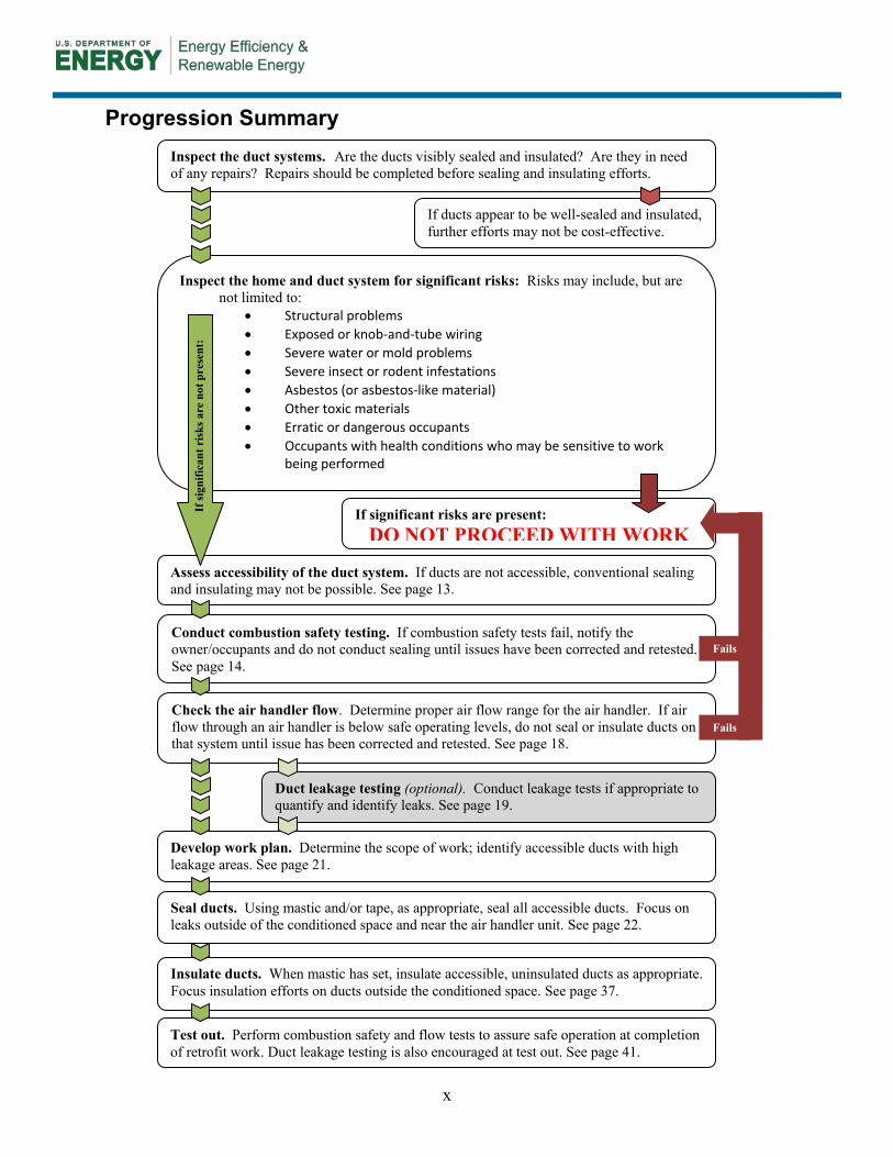
Progression Summary
Inspect the home and duct system for significant risks: Risks may include, but are not limited to:
• Structural problems • Exposed or knob-and-tube wiring • Severe water or mold problems • Severe insect or rodent infestations • Asbestos (or asbestos-like material) • Other toxic materials • Erratic or dangerous occupants • Occupants with health conditions who may be sensitive to work
being performed
If significant risks are present: DO NOT PROCEED WITH WORK
Assess accessibility of the duct system. If ducts are not accessible, conventional sealing and insulating may not be possible. See page 13.
If si
gnifi
cant
ris
ks a
re n
ot p
rese
nt:
Conduct combustion safety testing. If combustion safety tests fail, notify the owner/occupants and do not conduct sealing until issues have been corrected and retested. See page 14.
Check the air handler flow. Determine proper air flow range for the air handler. If air flow through an air handler is below safe operating levels, do not seal or insulate ducts on that system until issue has been corrected and retested. See page 18.
Duct leakage testing (optional). Conduct leakage tests if appropriate to quantify and identify leaks. See page 19.
Develop work plan. Determine the scope of work; identify accessible ducts with high leakage areas. See page 21.
Seal ducts. Using mastic and/or tape, as appropriate, seal all accessible ducts. Focus on leaks outside of the conditioned space and near the air handler unit. See page 22.
Insulate ducts. When mastic has set, insulate accessible, uninsulated ducts as appropriate. Focus insulation efforts on ducts outside the conditioned space. See page 37.
Test out. Perform combustion safety and flow tests to assure safe operation at completion of retrofit work. Duct leakage testing is also encouraged at test out. See page 41.
Fails
Fails
Inspect the duct systems. Are the ducts visibly sealed and insulated? Are they in need of any repairs? Repairs should be completed before sealing and insulating efforts.
If ducts appear to be well-sealed and insulated, further efforts may not be cost-effective.
1
1 Introduction
Ducts carry conditioned air between a central air handler and rooms throughout a home. In an ideal system, all of the supply air leaving the air handler would be transferred by the duct system to various points of use in the home and ultimately be discharged through supply registers within the rooms. Similarly, all of the return air in an ideal system would be drawn from the appropriate return air grilles, through return ducts, and back to the furnace or air handler. Historically, this has not been the case. According to the EPA ENERGY STAR® program, the typical home has 20% duct leakage. In older homes, it is not uncommon for duct leakage to account for 30%-50% of the total system air flow. Much higher leakage rates are possible in very poorly sealed systems. Ideally, duct leakage would be negligible, but a goal of less than 5% of the total system air flow is reasonable for newly installed systems. For existing duct systems, when parts of the duct system are not accessible, going from 30% leakage to 5% leakage is often not realistic. Ducts should be sealed as tightly as is practical, and this level varies tremendously from system to system.
When ducts are located in (or just passing through) unconditioned spaces such as attics or crawlspaces, a significant amount of energy–and heating and cooling capacity–can be lost. If ducts are located within conditioned parts of the home, duct leakage might not be a major energy liability, but still may lead to comfort issues.
Even when ducts are in conditioned space, duct leakage can prevent the proper amount of air from reaching the intended spaces. This can lead to comfort problems because portions of the home are over- or under-conditioned.
Duct leakage can also lead to pressure imbalances within homes. Such imbalances not only can affect comfort and efficiency, but can also impact health and durability. In homes with some types of combustion equipment, for example, large return duct leaks in a basement system can cause negative pressures which, in turn, can interfere with proper draft. Under these conditions, exhaust gases can be sucked into the home. Other risks of pressure imbalances include build up of moisture (and associated problems like mold) in parts of buildings.
Wherever ducts are located, duct leakage should be minimized for optimal efficiency, comfort, and durability in the home. While not addressed in building codes until recently, the 2009 International Energy Conservation Code (IECC) mandates duct leakage to outdoors be no more than 8 CFM25 per 100 ft2 of conditioned floor area (see section 403.2 of the 2009 IECC for details). High performance building programs, such as EPA’s ENERGY STAR Qualified Homes
Major Duct Retrofits
If major HVAC retrofits are planned as part of a project, the following resources may be helpful:
• Air Conditioning Contractors of America (ACCA) Manual J (8th edition), Manual D, Manual S, Manual T, Manual RS, and Standard 5: HVAC Quality Installation Specification
• EPA document “ENERGY STAR Qualified Homes, Version 3 (Rev. 02) HVAC System Quality Installation Contractor Checklist”
• ASHRAE Handbook of Fundamentals 2009
• Sheet Metal and Air Conditioning Contractors National Association (SMACNA) Residential Comfort System Installation Standards Manual
• Building Industry Institute’s Procedures for HVAC System Installation Scope of Work
• ASHRAE Standard 152 - Method of
Test for Determining the Design and Seasonal Efficiencies of Residential Thermal Distribution Systems
2
and USGBC’s LEED® for Homes, require total duct leakage to outdoors not be more than 4 CFM25 per 100 ft2 of conditioned floor area.
Similarly, duct insulation levels strongly impact distribution system performance. The most obvious benefit of insulating ducts is reducing the heat loss from (during heating) or heat gain to (during cooling) the ducted air. This is again more critical when ducts are located in unconditioned spaces, but there may be reasons to insulate ducts in conditioned spaces as well. In humid climates, proper duct insulation can prevent condensation on the cool surface of the ducts (and possible related moisture problems). In long duct runs, adding insulation will reduce energy loss as the air travels from the air handling unit to the supply registers. This will result in more desirable discharge air temperatures from registers, maximizing system capacity and potentially improving occupant comfort.
Note that this guide is only intended as a resource for sealing and insulating existing duct systems in homes; this is not intended as a guide for designing, installing, or performing major retrofits to HVAC systems. It is certainly true that a great many duct systems are poorly designed and installed, and reconfiguration may lead to improved efficiency and comfort.
3
2 Cost and Performance
While duct sealing can be a simple and effective way to improve home HVAC performance, the costs and benefits vary tremendously from home to home and across various climates. This section presents a framework and examples for assessing costs and benefits of duct sealing and insulation.
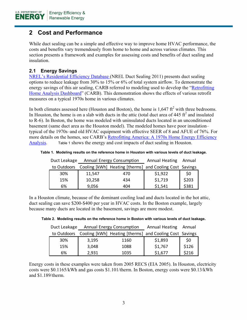
2.1 Energy Savings NREL’s Residential Efficiency Database (NREL Duct Sealing 2011) presents duct sealing options to reduce leakage from 30% to 15% or 6% of total system airflow. To demonstrate the energy savings of this air sealing, CARB referred to modeling used to develop the “Retrofitting Home Analysis Dashboard” (CARB). This demonstration shows the effects of various retrofit measures on a typical 1970s home in various climates.
In both climates assessed here (Houston and Boston), the home is 1,647 ft2 with three bedrooms. In Houston, the home is on a slab with ducts in the attic (total duct area of 445 ft2 and insulated to R-6). In Boston, the home was modeled with uninsulated ducts located in an unconditioned basement (same duct area as the Houston model). The modeled homes have poor insulation–typical of the 1970s–and old HVAC equipment with effective SEER of 8 and AFUE of 76%. For more details on the homes, see CARB’s Retrofitting America: A 1970s Home Energy Efficiency Analysis. Table 1 shows the energy and cost impacts of duct sealing in Houston.
Table 1. Modeling results on the reference home in Houston with various levels of duct leakage.
In a Houston climate, because of the dominant cooling load and ducts located in the hot attic, duct sealing can save $200-$400 per year in HVAC costs. In the Boston example, largely because many ducts are located in the basement, savings are more modest.
Table 2. Modeling results on the reference home in Boston with various levels of duct leakage.
Energy costs in these examples were taken from 2005 RECS (EIA 2005). In Houston, electricity costs were $0.1165/kWh and gas costs $1.101/therm. In Boston, energy costs were $0.13/kWh and $1.189/therm.
Duct Leakage Annual Heating Annualto Outdoors Cooling [kWh] Heating [therms] and Cooling Cost Savings
30% 11,547 470 $1,922 $015% 10,258 434 $1,719 $2036% 9,056 404 $1,541 $381
Annual Energy Consumption
Duct Leakage Annual Heating Annualto Outdoors Cooling [kWh] Heating [therms] and Cooling Cost Savings
30% 3,195 1160 $1,893 $015% 3,048 1088 $1,767 $1266% 2,931 1035 $1,677 $216
Annual Energy Consumption
4
Of course, the savings achieved by duct sealing depends on many, many factors. These examples simply demonstrate that duct leakage can indeed account for a significant portion of heating and cooling costs.
Energy savings from duct insulation varies with the initial state of duct insulation, the duct locations, and how much of the duct system one can effectively insulate. In the examples above, going from entirely uninsulated ducts to R-6 ducts will save approximately $100 per year in both climates (Boston and Houston). Going to R-8 duct insulation provides modest additional savings of $5 per year.
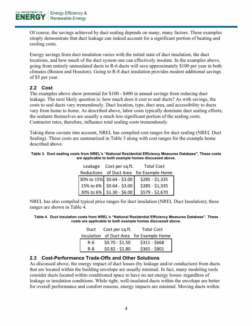
2.2 Cost The examples above show potential for $100 - $400 in annual savings from reducing duct leakage. The next likely question is: how much does it cost to seal ducts? As with savings, the costs to seal ducts vary tremendously. Duct location, type, duct area, and accessibility to ducts vary from home to home. As described above, labor costs typically dominate duct sealing efforts; the sealants themselves are usually a much less significant portion of the sealing costs. Contractor rates, therefore, influence total sealing costs tremendously.
Taking these caveats into account, NREL has compiled cost ranges for duct sealing (NREL Duct Sealing). These costs are summarized in Table 3 along with cost ranges for the example home described above.
Table 3. Duct sealing costs from NREL’s “National Residential Efficiency Measures Database”. These costs are applicable to both example homes discussed above.
NREL has also compiled typical price ranges for duct insulation (NREL Duct Insulation); these ranges are shown in Table 4.
Table 4. Duct insulation costs from NREL’s “National Residential Efficiency Measures Database”. These costs are applicable to both example homes discussed above.
2.3 Cost-Performance Trade-Offs and Other Solutions As discussed above, the energy impact of duct losses (by leakage and/or conduction) from ducts that are located within the building envelope are usually minimal. In fact, many modeling tools consider ducts located within conditioned space to have no net energy losses–regardless of leakage or insulation conditions. While tight, well-insulated ducts within the envelope are better for overall performance and comfort reasons, energy impacts are minimal. Moving ducts within
Leakage Cost per sq.ft. Total CostReductions of Duct Area for Example Home30% to 15% $0.64 - $3.00 $285 - $1,33515% to 6% $0.64 - $3.00 $285 - $1,33530% to 6% $1.30 - $6.00 $579 - $2,670
Duct Cost per sq.ft. Total CostInsulation of Duct Area for Example Home
R-6 $0.70 - $1.50 $311 - $668R-8 $0.82 - $1.80 $365 - $801
5
conditioned space (or expanding conditioned space to encapsulate ducts) is sometimes a viable retrofit strategy.
Aside from moving ducts into conditioned space, and short of complete removal and/or replacement of a forced-air HVAC system, there is no good substitute for duct sealing and insulating. As home heating and cooling loads are reduced (from envelope improvements, high-efficiency equipment, etc.), the relative impact of duct losses will change, but these losses can still be a liability with respect to energy, equipment capacity, and comfort.
2.4 Non-Energy Benefits There are three potential benefits from reducing duct losses: comfort, HVAC capacity, and IAQ/combustion safety
2.4.1 Comfort The comfort benefits are very straight-forward. If heat (or “coolness”) is lost from a duct before the air reaches the register, the room where that register is located will receive less heating or cooling. In large homes, exterior rooms with long, leaky duct runs can be much less comfortable than inner rooms with shorter ducts runs (and possibly where thermostats are located).
2.4.2 HVAC Capacity If a home requires four tons of cooling, and duct losses amount to one additional ton (easily possible with duct leakage over 20%), a five-ton AC system would be needed to meet the loads under design conditions. If a four-ton system was installed, there would likely be comfort problems on design days.
These capacity issues are often compounded by extreme conditions, especially when ducts are located in the attic. On hot summer days, attic temperatures can easily reach 130°F or 140°F. Supply ducts that carry 50°F -55°F air experience at least an 80°F temperature differential; return leaks can draw in 130°F attic air–this obviously requires much more power to cool than indoor air at around 75°F.
Minimizing duct losses can allow for smaller equipment–especially with respect to cooling. If equipment capacity is already stretched, reducing or eliminating duct losses can allow more of the heating and cooling capacity to be delivered to the home.
2.4.3 IAQ and Combustion Safety Duct leakage can cause pressure imbalances in homes. Excessive supply leaks can cause a home to be depressurized; this, in turn, can cause drafting problems and can potentially draw combustion products into the home. Depressurization in hot, humid climates can also lead to moisture problems if humid outdoor air is drawn into cooler envelope assemblies.
To minimize combustion safety risks, combustion safety testing should be conducted both before and after duct sealing is performed.
6
3 Ductwork Components
3.1 Duct Materials This section discusses the three most common duct materials: sheet metal, fiberglass duct board, and flexible duct (typically referred to as “flex duct”). Each material has advantages and disadvantages and can require different approaches for insulating and air sealing. A duct distribution system may utilize a combination of these materials, such as sheet metal trunks off the air handling unit and flex duct branches to supply the individual registers.
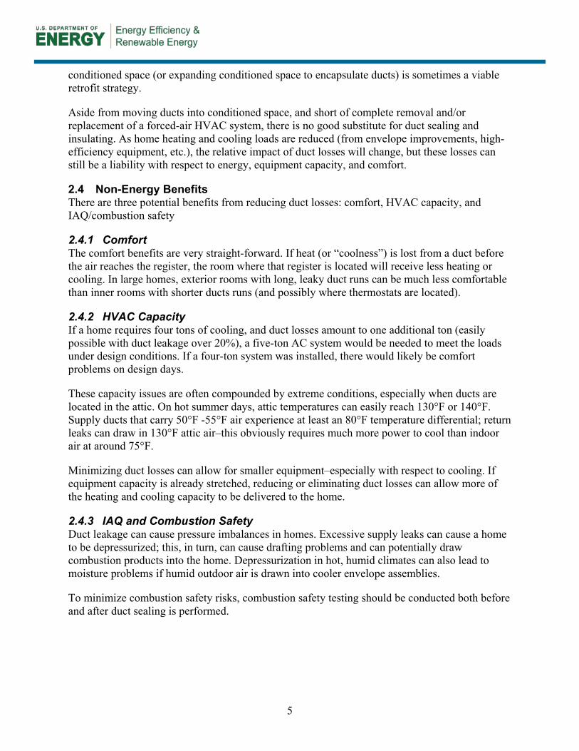
3.1.1 Sheet Metal Galvanized steel metal is a very common duct material and is required in some jurisdictions. Round and rectangular shapes are the most common, but ovals and other shapes are sometimes used. There is also a wide array of sheet metal fittings that connect sections of duct (elbows, transitions, takeoffs, reducers, etc.).
Figure 1. Sheet metal supply plenum sealed with mastic. A flexible, fireproof canvas collar was installed to provide sound/vibration attenuation.
Screws are typically used to connect straight round ducts to collars, elbows, T’s, Y’s, reductions, boots, and other fittings. SMACNA recommends using at least three #8 sheet metal screws spaced equidistant. If seams, gaps, and connections are not sealed before insulation, substantial leakage can result.
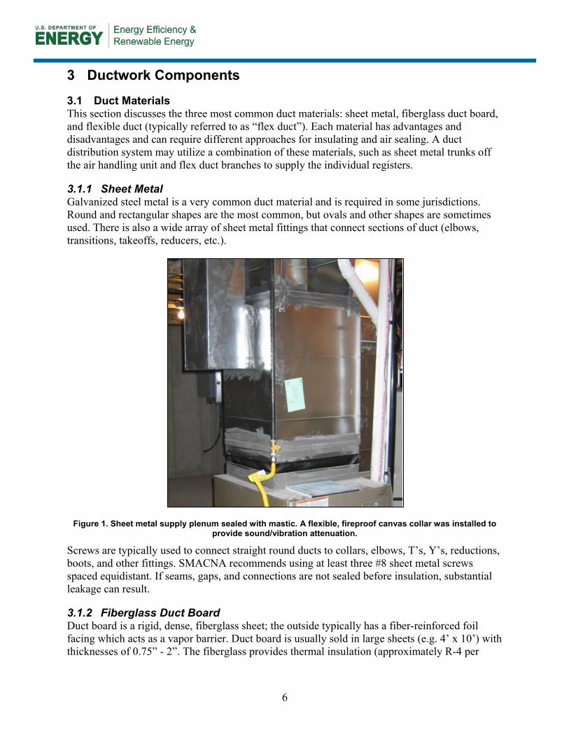
3.1.2 Fiberglass Duct Board Duct board is a rigid, dense, fiberglass sheet; the outside typically has a fiber-reinforced foil facing which acts as a vapor barrier. Duct board is usually sold in large sheets (e.g. 4’ x 10’) with thicknesses of 0.75” - 2”. The fiberglass provides thermal insulation (approximately R-4 per
7
inch) as well as sound attenuation. Duct board is typically cut, folded, and shaped into rectangular sections of duct. Duct board is primarily used for plenums, trunks, and junction boxes; smaller branch ducts can be sheet metal or, more commonly, insulated flex duct. As with sheet metal, the most common areas for leakage are at collars, transitions, or connections to other materials.
Figure 2. Fiberglass duct board ducts in an attic
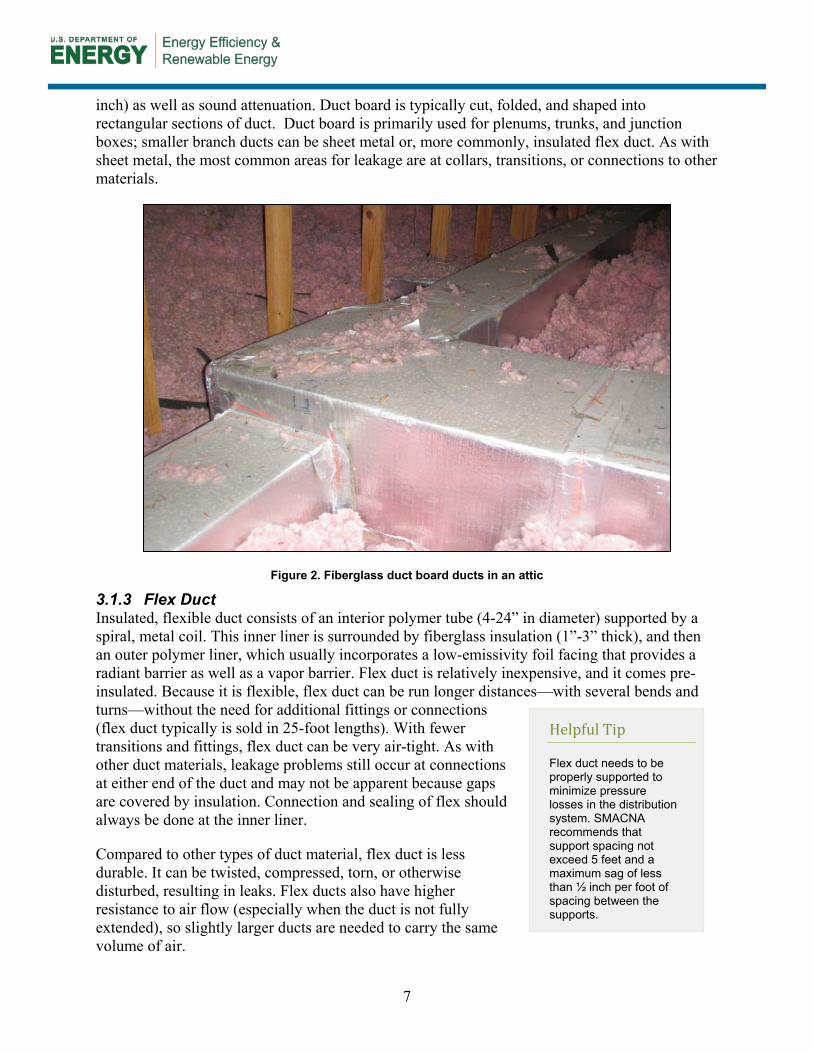
3.1.3 Flex Duct Insulated, flexible duct consists of an interior polymer tube (4-24” in diameter) supported by a spiral, metal coil. This inner liner is surrounded by fiberglass insulation (1”-3” thick), and then an outer polymer liner, which usually incorporates a low-emissivity foil facing that provides a radiant barrier as well as a vapor barrier. Flex duct is relatively inexpensive, and it comes pre-insulated. Because it is flexible, flex duct can be run longer distances—with several bends and turns—without the need for additional fittings or connections (flex duct typically is sold in 25-foot lengths). With fewer transitions and fittings, flex duct can be very air-tight. As with other duct materials, leakage problems still occur at connections at either end of the duct and may not be apparent because gaps are covered by insulation. Connection and sealing of flex should always be done at the inner liner.
Compared to other types of duct material, flex duct is less durable. It can be twisted, compressed, torn, or otherwise disturbed, resulting in leaks. Flex ducts also have higher resistance to air flow (especially when the duct is not fully extended), so slightly larger ducts are needed to carry the same volume of air.
Helpful Tip
Flex duct needs to be properly supported to minimize pressure losses in the distribution system. SMACNA recommends that support spacing not exceed 5 feet and a maximum sag of less than ½ inch per foot of spacing between the supports.
8
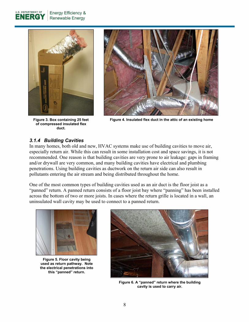
3.1.4 Building Cavities In many homes, both old and new, HVAC systems make use of building cavities to move air, especially return air. While this can result in some installation cost and space savings, it is not recommended. One reason is that building cavities are very prone to air leakage: gaps in framing and/or drywall are very common, and many building cavities have electrical and plumbing penetrations. Using building cavities as ductwork on the return air side can also result in pollutants entering the air stream and being distributed throughout the home.
One of the most common types of building cavities used as an air duct is the floor joist as a “panned” return. A panned return consists of a floor joist bay where “panning” has been installed across the bottom of two or more joists. In cases where the return grille is located in a wall, an uninsulated wall cavity may be used to connect to a panned return.
Figure 4. Insulated flex duct in the attic of an existing home
Figure 3. Box containing 25 feet
of compressed insulated flex duct.
Figure 6. A “panned” return where the building cavity is used to carry air.
Figure 5. Floor cavity being used as return pathway. Note the electrical penetrations into
this “panned” return.
9
3.2 Sealants Ironically, most conventional “duct tape” is not an acceptable product for duct sealing. Proper duct sealants are classified according to two Underwriters Laboratories standards:
• UL-181A, “Standard for Closure Systems for Use With Rigid Air Ducts”
• UL-181B, “Standard for Closure Systems for Use With Flexible Air Ducts and Air”
These standards generally describe the air sealing of new duct systems; bringing older systems up to these levels may not be possible or practical. At a minimum, however, duct sealing products should meet the requirements of the appropriate standard above; these products will be labeled “UL181A” or “UL181B”. Many materials are approved for both A and B, i.e. for sealing both rigid and flexible ducts. Language from Section M1604.4.1 of the 2009 International Residential Code (IRC) may be appropriate to incorporate into duct sealing scopes of work (see sidebar).
ACCA Standard 5: HVAC Quality Installation Specification and the companion Checklist are useful resources for HVAC contractor scopes of work if a major overhaul of the existing duct system is being performed. Another excellent resource is a document published by the U.S. Department of Energy’s Building Technologies Program called “Air Distribution System Installation and Sealing: Proper Duct Installation Increases Efficiency.”
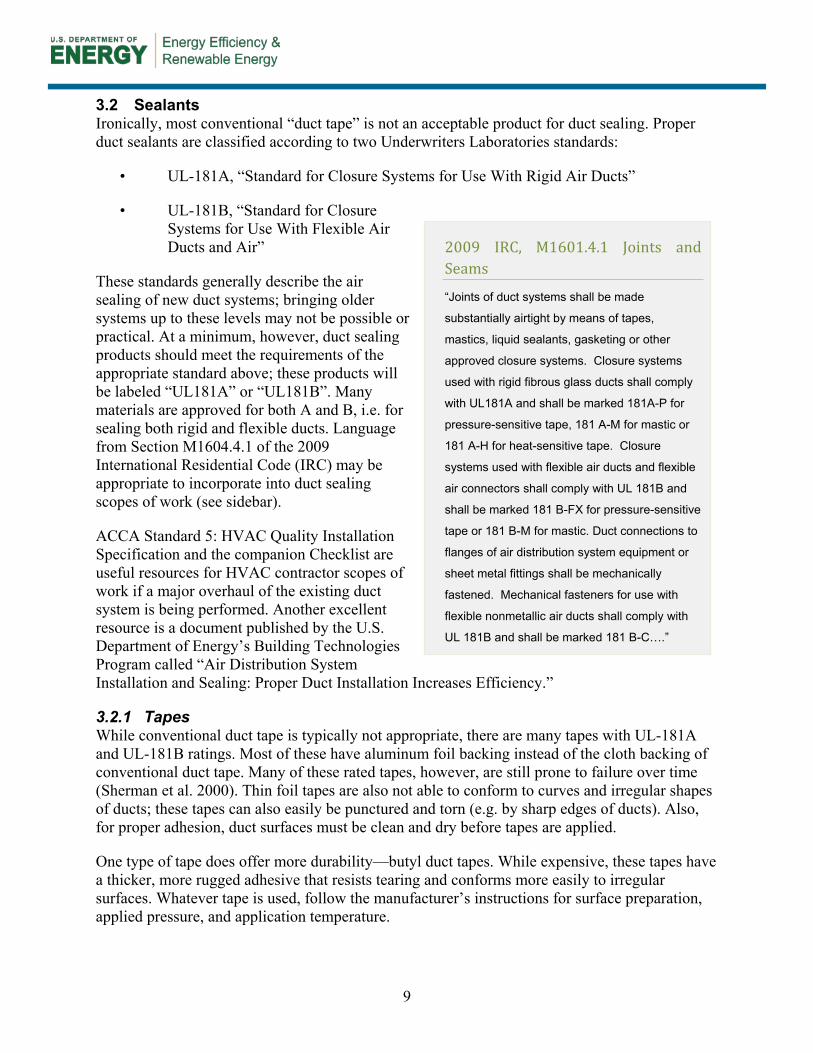
3.2.1 Tapes While conventional duct tape is typically not appropriate, there are many tapes with UL-181A and UL-181B ratings. Most of these have aluminum foil backing instead of the cloth backing of conventional duct tape. Many of these rated tapes, however, are still prone to failure over time (Sherman et al. 2000). Thin foil tapes are also not able to conform to curves and irregular shapes of ducts; these tapes can also easily be punctured and torn (e.g. by sharp edges of ducts). Also, for proper adhesion, duct surfaces must be clean and dry before tapes are applied.
One type of tape does offer more durability—butyl duct tapes. While expensive, these tapes have a thicker, more rugged adhesive that resists tearing and conforms more easily to irregular surfaces. Whatever tape is used, follow the manufacturer’s instructions for surface preparation, applied pressure, and application temperature.
2009 IRC, M1601.4.1 Joints and Seams
“Joints of duct systems shall be made
substantially airtight by means of tapes,
mastics, liquid sealants, gasketing or other
approved closure systems. Closure systems
used with rigid fibrous glass ducts shall comply
with UL181A and shall be marked 181A-P for
pressure-sensitive tape, 181 A-M for mastic or
181 A-H for heat-sensitive tape. Closure
systems used with flexible air ducts and flexible
air connectors shall comply with UL 181B and
shall be marked 181 B-FX for pressure-sensitive
tape or 181 B-M for mastic. Duct connections to
flanges of air distribution system equipment or
sheet metal fittings shall be mechanically
fastened. Mechanical fasteners for use with
flexible nonmetallic air ducts shall comply with
UL 181B and shall be marked 181 B-C….”
10
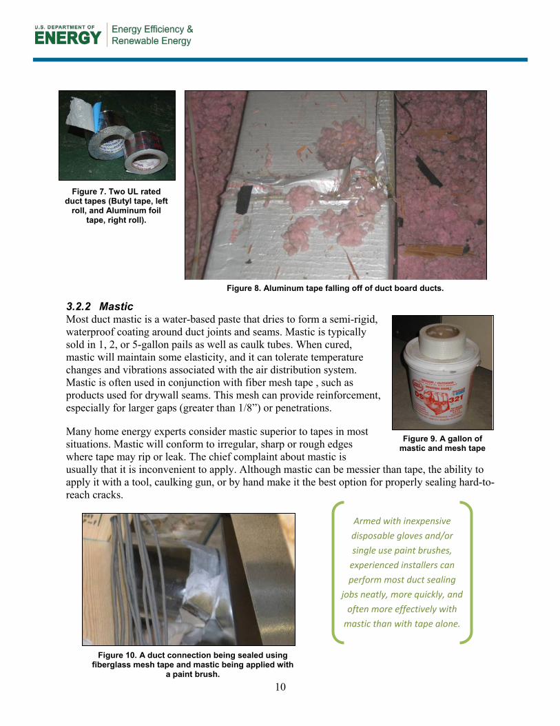
3.2.2 Mastic Most duct mastic is a water-based paste that dries to form a semi-rigid, waterproof coating around duct joints and seams. Mastic is typically sold in 1, 2, or 5-gallon pails as well as caulk tubes. When cured, mastic will maintain some elasticity, and it can tolerate temperature changes and vibrations associated with the air distribution system. Mastic is often used in conjunction with fiber mesh tape , such as products used for drywall seams. This mesh can provide reinforcement, especially for larger gaps (greater than 1/8”) or penetrations.
Many home energy experts consider mastic superior to tapes in most situations. Mastic will conform to irregular, sharp or rough edges where tape may rip or leak. The chief complaint about mastic is usually that it is inconvenient to apply. Although mastic can be messier than tape, the ability to apply it with a tool, caulking gun, or by hand make it the best option for properly sealing hard-to-reach cracks.
Figure 7. Two UL rated duct tapes (Butyl tape, left
roll, and Aluminum foil tape, right roll).
Figure 8. Aluminum tape falling off of duct board ducts.
Figure 9. A gallon of mastic and mesh tape
Armed with inexpensive
disposable gloves and/or
single use paint brushes,
experienced installers can
perform most duct sealing
jobs neatly, more quickly, and
often more effectively with
mastic than with tape alone.
Figure 10. A duct connection being sealed using fiberglass mesh tape and mastic being applied with
a paint brush.
11
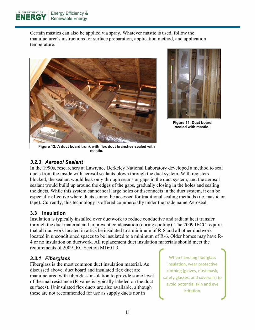
Certain mastics can also be applied via spray. Whatever mastic is used, follow the manufacturer’s instructions for surface preparation, application method, and application temperature.
3.2.3 Aerosol Sealant In the 1990s, researchers at Lawrence Berkeley National Laboratory developed a method to seal ducts from the inside with aerosol sealants blown through the duct system. With registers blocked, the sealant would leak only through seams or gaps in the duct system; and the aerosol sealant would build up around the edges of the gaps, gradually closing in the holes and sealing the ducts. While this system cannot seal large holes or disconnects in the duct system, it can be especially effective where ducts cannot be accessed for traditional sealing methods (i.e. mastic or tape). Currently, this technology is offered commercially under the trade name Aeroseal.
3.3 Insulation Insulation is typically installed over ductwork to reduce conductive and radiant heat transfer through the duct material and to prevent condensation (during cooling). The 2009 IECC requires that all ductwork located in attics be insulated to a minimum of R-8 and all other ductwork located in unconditioned spaces to be insulated to a minimum of R-6. Older homes may have R-4 or no insulation on ductwork. All replacement duct insulation materials should meet the requirements of 2009 IRC Section M1601.3.
3.3.1 Fiberglass Fiberglass is the most common duct insulation material. As discussed above, duct board and insulated flex duct are manufactured with fiberglass insulation to provide some level of thermal resistance (R-value is typically labeled on the duct surfaces). Uninsulated flex ducts are also available, although these are not recommended for use as supply ducts nor in
Figure 12. A duct board trunk with flex duct branches sealed with mastic.
Figure 11. Duct board sealed with mastic.
When handling fiberglass
insulation, wear protective
clothing (gloves, dust mask,
safety glasses, and coveralls) to
avoid potential skin and eye
irritation.
12
unconditioned spaces (return ducts within conditioned space may be an acceptable application for uninsulated flex). Uninsulated flex ducts are sometimes found in systems that were installed or retrofitted by a layperson. In cases where uninsulated flex duct is found, insulation strategies similar to those discussed below for use on sheet metal ductwork can be utilized.
Most sheet metal ducts are uninsulated or wrapped on the outside with fiberglass insulation blankets, sometimes called “duct wrap”. These sheets (typically 2-4 feet wide) are 1-4” thick and include a
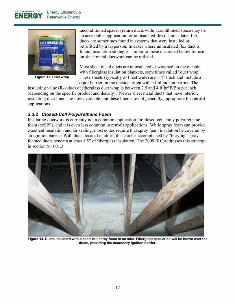
vapor barrier on the outside, often with a foil radiant barrier. The insulating value (R-value) of fiberglass duct wrap is between 2.5 and 4 ft2hr°F/Btu per inch (depending on the specific product and density). Newer sheet metal ducts that have interior, insulating duct liners are now available, but these liners are not generally appropriate for retrofit applications. 3.3.2 Closed-Cell Polyurethane Foam Insulating ductwork is currently not a common application for closed-cell spray polyurethane foam (ccSPF), and it is even less common in retrofit applications. While spray foam can provide excellent insulation and air sealing, most codes require that spray foam insulation be covered by an ignition barrier. With ducts located in attics, this can be accomplished by “burying” spray-foamed ducts beneath at least 1.5” of fiberglass insulation. The 2009 IRC addresses this strategy in section M1601.3.
Figure 14. Ducts insulated with closed-cell spray foam in an attic. Fiberglass insulation will be blown over the
ducts, providing the necessary ignition barrier.
Figure 13. Duct wrap
13
4 Health and Safety
Before describing duct diagnostics, sealing, or insulating procedures, it is important to understand basic health and safety information. Prior to beginning any work, inspect the home and systems to determine if the duct improvement work can be performed safely. It may be appropriate to refer to standards such as the Building Performance Institute’s (BPI’s) “Technical Standards for the Building Analyst Professional” or other protocols.
The contents of this section are provided as suggestions. Contractors should refer to appropriate local codes, regulations, professional standards, and common sense as the situation warrants.
4.1 Inspect the House and HVAC Systems • Structural Issues: If the building is damaged or
structurally unsound, duct sealing work should not be pursued until other repairs are completed.
• Duct Status: Ducts that are disconnected, damaged, or designed poorly can result in poor HVAC performance. If duct systems are to be modified or improved, this should be done before sealing and insulating efforts.
• Asbestos, Mold, and Other Contaminants: If there is an existing mold problem in the building or in the ductwork, or if possible asbestos-containing material is present, the conditions should be documented and assessed to determine if testing and sealing can safely be completed. If testing and sealing cannot be safely completed, the homeowner should be instructed to have the problem(s) addressed by a qualified professional before continuing with duct sealing work.
• Health/Safety of the Occupants: If there are people living in the home with severe medical conditions, the situation should be evaluated to ensure that the duct testing and sealing will not cause adverse health conditions. This could include stirring up dust, blowing cold air into the house, shutting off systems to complete work during extreme weather, etc.
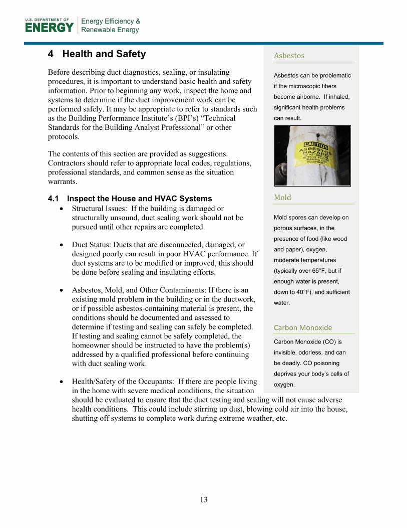
Asbestos
Asbestos can be problematic
if the microscopic fibers
become airborne. If inhaled,
significant health problems
can result.
Mold
Mold spores can develop on
porous surfaces, in the
presence of food (like wood
and paper), oxygen,
moderate temperatures
(typically over 65°F, but if
enough water is present,
down to 40°F), and sufficient
water.
Carbon Monoxide
Carbon Monoxide (CO) is
invisible, odorless, and can
be deadly. CO poisoning
deprives your body’s cells of
oxygen.
14
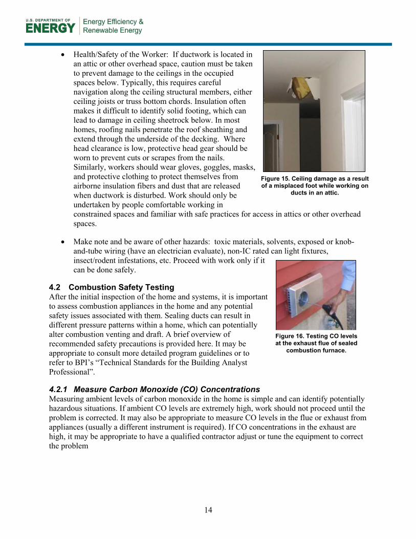
• Health/Safety of the Worker: If ductwork is located in an attic or other overhead space, caution must be taken to prevent damage to the ceilings in the occupied spaces below. Typically, this requires careful navigation along the ceiling structural members, either ceiling joists or truss bottom chords. Insulation often makes it difficult to identify solid footing, which can lead to damage in ceiling sheetrock below. In most homes, roofing nails penetrate the roof sheathing and extend through the underside of the decking. Where head clearance is low, protective head gear should be worn to prevent cuts or scrapes from the nails. Similarly, workers should wear gloves, goggles, masks, and protective clothing to protect themselves from airborne insulation fibers and dust that are released when ductwork is disturbed. Work should only be undertaken by people comfortable working in constrained spaces and familiar with safe practices for access in attics or other overhead spaces.
• Make note and be aware of other hazards: toxic materials, solvents, exposed or knob-and-tube wiring (have an electrician evaluate), non-IC rated can light fixtures, insect/rodent infestations, etc. Proceed with work only if it can be done safely.
4.2 Combustion Safety Testing After the initial inspection of the home and systems, it is important to assess combustion appliances in the home and any potential safety issues associated with them. Sealing ducts can result in different pressure patterns within a home, which can potentially alter combustion venting and draft. A brief overview of recommended safety precautions is provided here. It may be appropriate to consult more detailed program guidelines or to refer to BPI’s “Technical Standards for the Building Analyst Professional”.
4.2.1 Measure Carbon Monoxide (CO) Concentrations Measuring ambient levels of carbon monoxide in the home is simple and can identify potentially hazardous situations. If ambient CO levels are extremely high, work should not proceed until the problem is corrected. It may also be appropriate to measure CO levels in the flue or exhaust from appliances (usually a different instrument is required). If CO concentrations in the exhaust are high, it may be appropriate to have a qualified contractor adjust or tune the equipment to correct the problem
Figure 15. Ceiling damage as a result of a misplaced foot while working on
ducts in an attic.
Figure 16. Testing CO levels at the exhaust flue of sealed
combustion furnace.
15
Table 5. Exposure limits for carbon monoxide (CO).1
Agency / Organization
Maximum CO Concentrations Occupational Safety and Health
Administration (OSHA) 50 ppm as an 8-hour time-weighted
average National Institute for Occupational Safety and
Health (NIOSH) 35 ppm as an 8-hour time-weighted
average AND 200 ppm at any time
American Conference of Governmental Industrial Hygienists (ACGIH)
25 ppm as an 8-hour time-weighted average for a 40-hour work week.
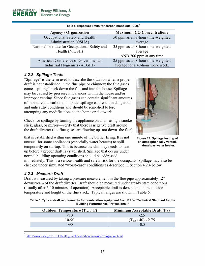
4.2.2 Spillage Tests “Spillage” is the term used to describe the situation when a proper draft is not established in the flue pipe or chimney; the flue gases come “spilling” back down the flue and into the house. Spillage may be caused by pressure imbalances within the house and/or improper venting. Since flue gases can contain significant amounts of moisture and carbon monoxide, spillage can result in dangerous and unhealthy conditions and should be remedied before attempting any modifications to the home or ductwork.
Check for spillage by turning the appliance on and - using a smoke stick, glass, or mirror—verify that there is negative draft around the draft diverter (i.e. flue gases are flowing up–not down–the flue)
that is established within one minute of the burner firing. It is not unusual for some appliances (especially water heaters) to spill temporarily on startup. This is because the chimney needs to heat up before a proper draft is established. Spillage that occurs under normal building operating conditions should be addressed immediately. This is a serious health and safety risk for the occupants. Spillage may also be checked under simulated “worst-case” conditions as described in Section 4.2.4 below.
4.2.3 Measure Draft Draft is measured by taking a pressure measurement in the flue pipe approximately 12” downstream of the draft diverter. Draft should be measured under steady state conditions (usually after 5-10 minutes of operation). Acceptable draft is dependent on the outside temperature and height of the flue stack. Typical ranges are shown in Table 6.
Table 6. Typical draft requirements for combustion equipment from BPI’s “Technical Standard for the Building Performance Professional.”
Outdoor Temperature (Tout, °F) Minimum Acceptable Draft (Pa) <10 -2.5
10-90 (Tout / 40) - 2.75 >90 -0.5
1 http://www.osha.gov/SLTC/healthguidelines/carbonmonoxide/recognition.html
Figure 17. Spillage testing of an atmospherically vented, natural gas water heater.
16
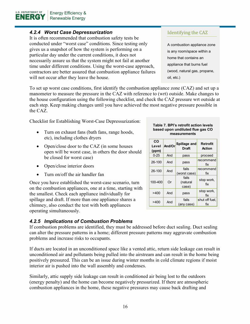
4.2.4 Worst Case Depressurization It is often recommended that combustion safety tests be conducted under “worst case” conditions. Since testing only gives us a snapshot of how the system is performing on a particular day under the current conditions, it does not necessarily assure us that the system might not fail at another time under different conditions. Using the worst-case approach, contractors are better assured that combustion appliance failures will not occur after they leave the house.
To set up worst case conditions, first identify the combustion appliance zone (CAZ) and set up a manometer to measure the pressure in the CAZ with reference to (wrt) outside. Make changes to the house configuration using the following checklist, and check the CAZ pressure wrt outside at each step. Keep making changes until you have achieved the most negative pressure possible in the CAZ.
Checklist for Establishing Worst-Case Depressurization:
• Turn on exhaust fans (bath fans, range hoods, etc), including clothes dryers
• Open/close door to the CAZ (in some houses open will be worst case, in others the door should be closed for worst case)
• Open/close interior doors
• Turn on/off the air handler fan
Once you have established the worst-case scenario, turn on the combustion appliances, one at a time, starting with the smallest. Check each appliance individually for spillage and draft. If more than one appliance shares a chimney, also conduct the test with both appliances operating simultaneously.
4.2.5 Implications of Combustion Problems If combustion problems are identified, they must be addressed before duct sealing. Duct sealing can alter the pressure patterns in a home; different pressure patterns may aggravate combustion problems and increase risks to occupants.
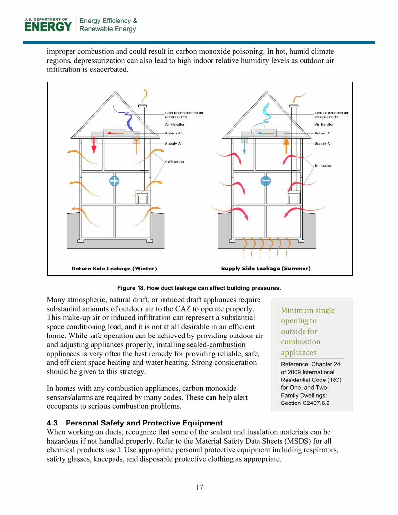
If ducts are located in an unconditioned space like a vented attic, return side leakage can result in unconditioned air and pollutants being pulled into the airstream and can result in the home being positively pressured. This can be an issue during winter months in cold climate regions if moist interior air is pushed into the wall assembly and condenses.
Similarly, attic supply side leakage can result in conditioned air being lost to the outdoors (energy penalty) and the home can become negatively pressurized. If there are atmospheric combustion appliances in the home, these negative pressures may cause back drafting and
Identifying the CAZ
A combustion appliance zone
is any room/space within a
home that contains an
appliance that burns fuel
(wood, natural gas, propane,
oil, etc.)
Table 7. BPI’s retrofit action levels based upon undiluted flue gas CO
measurements
CO Level (ppm)
And/Or Spillage and Draft
Retrofit Action
0-25 And pass proceed
26-100 And pass recommend fix
26-100 And fails (worst case)
recommend fix
100-400 Orfails
(natural case)
stop work, fix
>400 And pass stop work, fix
>400 Andfails
(any case)shut off fuel,
fix
17
improper combustion and could result in carbon monoxide poisoning. In hot, humid climate regions, depressurization can also lead to high indoor relative humidity levels as outdoor air infiltration is exacerbated.
Figure 18. How duct leakage can affect building pressures.
Many atmospheric, natural draft, or induced draft appliances require substantial amounts of outdoor air to the CAZ to operate properly. This make-up air or induced infiltration can represent a substantial space conditioning load, and it is not at all desirable in an efficient home. While safe operation can be achieved by providing outdoor air and adjusting appliances properly, installing sealed-combustion
In homes with any combustion appliances, carbon monoxide sensors/alarms are required by many codes. These can help alert occupants to serious combustion problems.
appliances is very often the best remedy for providing reliable, safe, and efficient space heating and water heating. Strong consideration should be given to this strategy.
4.3 Personal Safety and Protective Equipment When working on ducts, recognize that some of the sealant and insulation materials can be hazardous if not handled properly. Refer to the Material Safety Data Sheets (MSDS) for all chemical products used. Use appropriate personal protective equipment including respirators, safety glasses, kneepads, and disposable protective clothing as appropriate.
Minimum single opening to outside for combustion appliances Reference: Chapter 24 of 2009 International Residential Code (IRC) for One- and Two-Family Dwellings; Section G2407.6.2
18
5 Evaluating Duct Systems
5.1 Check Airflow of System(s) Furnaces and air conditioners are both designed to run within certain airflow ranges to ensure proper and safe performance. Before sealing ducts, system air flow should be measured. If flow is not in an acceptable range, correct the airflow before continuing with sealing. Sealing a very leaky duct system can increase pressure and therefore reduce total airflow. Air flow should be checked after sealing as well to ensure proper operation.
High airflow during cooling operation may result in inadequate dehumidification. Low airflow is also a problem, as too little heat exchange may occur at the evaporator coil. This can cause liquid refrigerant to return to the compressor and damage the motor. Improper airflow may also cause icing of the evaporator coil.
Below are several methods for measuring airflow through air handlers, any of which may be acceptable if performed properly. Typically, air conditioners require airflow of no less than 300-350 cfm per ton of cooling. Some manufacturers may have somewhat different requirements for particular models, but a 350 cfm/ton minimum may be a good rule of thumb (see side bar for more climate specific “rules of thumb”) when the manufacturer’s specifications are not readily available. When nominal furnace flow rates are not available during heating operation, 21.7 cfm/kBtu/h is a default value recommended in California energy codes (CEC).
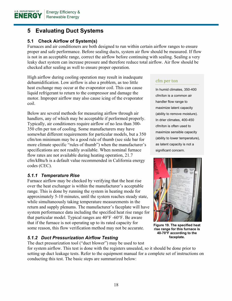
5.1.1 Temperature Rise Furnace airflow may be checked by verifying that the heat rise over the heat exchanger is within the manufacturer’s acceptable range. This is done by running the system in heating mode for approximately 5-10 minutes, until the system reaches steady state, while simultaneously taking temperature measurements in the return and supply plenums. The manufacturer’s faceplate will have system performance data including the specified heat rise range for that particular model. Typical ranges are 40°F -60°F. Be aware that if the furnace is not operating up to its rated capacity for some reason, this flow verification method may not be accurate.
5.1.2 Duct Pressurization Airflow Testing The duct pressurization tool (“duct blower”) may be used to test for system airflow. This test is done with the registers unsealed, so it should be done prior to setting up duct leakage tests. Refer to the equipment manual for a complete set of instructions on conducting this test. The basic steps are summarized below:
Figure 19. The specified heat rise range for this furnace is
40-70°F according to the faceplate.
cfm per ton
In humid climates, 350-400
cfm/ton is a common air
handler flow range to
maximize latent capacity
(ability to remove moisture).
In drier climates, 400-450
cfm/ton is often used to
maximize sensible capacity
(ability to lower temperature),
as latent capacity is not a
significant concern.
19
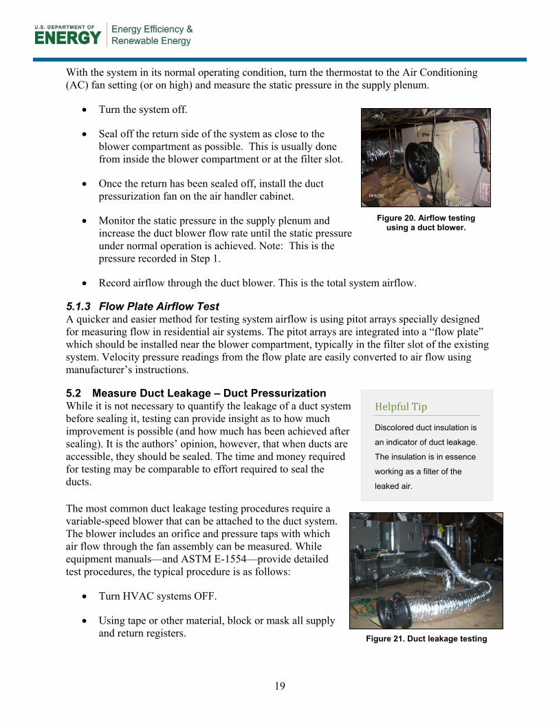
With the system in its normal operating condition, turn the thermostat to the Air Conditioning (AC) fan setting (or on high) and measure the static pressure in the supply plenum.
• Turn the system off.
• Seal off the return side of the system as close to the blower compartment as possible. This is usually done from inside the blower compartment or at the filter slot.
• Once the return has been sealed off, install the duct pressurization fan on the air handler cabinet.
• Monitor the static pressure in the supply plenum and increase the duct blower flow rate until the static pressure under normal operation is achieved. Note: This is the pressure recorded in Step 1.
• Record airflow through the duct blower. This is the total system airflow.
5.1.3 Flow Plate Airflow Test A quicker and easier method for testing system airflow is using pitot arrays specially designed for measuring flow in residential air systems. The pitot arrays are integrated into a “flow plate” which should be installed near the blower compartment, typically in the filter slot of the existing system. Velocity pressure readings from the flow plate are easily converted to air flow using manufacturer’s instructions.
5.2 Measure Duct Leakage – Duct Pressurization While it is not necessary to quantify the leakage of a duct system before sealing it, testing can provide insight as to how much improvement is possible (and how much has been achieved after sealing). It is the authors’ opinion, however, that when ducts are accessible, they should be sealed. The time and money required for testing may be comparable to effort required to seal the ducts. The most common duct leakage testing procedures require a variable-speed blower that can be attached to the duct system. The blower includes an orifice and pressure taps with which air flow through the fan assembly can be measured. While equipment manuals—and ASTM E-1554—provide detailed test procedures, the typical procedure is as follows:
• Turn HVAC systems OFF.
• Using tape or other material, block or mask all supply and return registers.
Figure 20. Airflow testing using a duct blower.
Helpful Tip
Discolored duct insulation is
an indicator of duct leakage.
The insulation is in essence
working as a filter of the
leaked air.
Figure 21. Duct leakage testing
20
• Attach the blower to the duct system – typically at the return side of the air handler.
• Insert a static pressure reference tap—typically in the supply plenum.
• Turn on the fan and pressurize the duct system to the appropriate level (e.g. 25 Pa with respect to outdoors).
• Measure the flow rate through the fan; this is the total duct leakage.
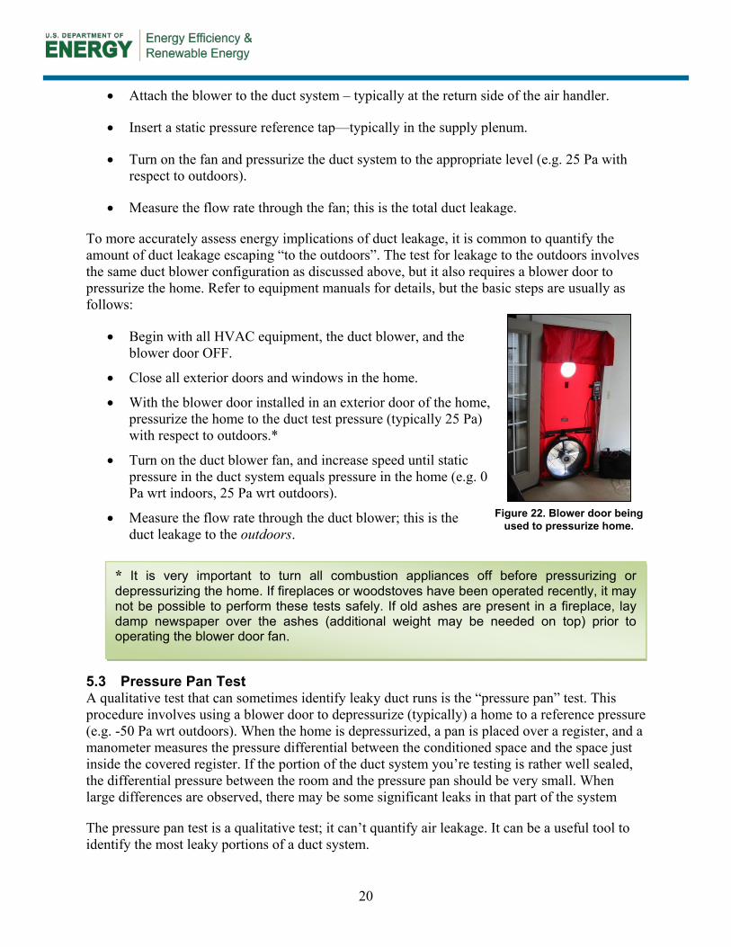
To more accurately assess energy implications of duct leakage, it is common to quantify the amount of duct leakage escaping “to the outdoors”. The test for leakage to the outdoors involves the same duct blower configuration as discussed above, but it also requires a blower door to pressurize the home. Refer to equipment manuals for details, but the basic steps are usually as follows:
• Begin with all HVAC equipment, the duct blower, and the blower door OFF.
• Close all exterior doors and windows in the home.
• With the blower door installed in an exterior door of the home, pressurize the home to the duct test pressure (typically 25 Pa) with respect to outdoors.*
• Turn on the duct blower fan, and increase speed until static pressure in the duct system equals pressure in the home (e.g. 0 Pa wrt indoors, 25 Pa wrt outdoors).
• Measure the flow rate through the duct blower; this is the duct leakage to the outdoors.
5.3 Pressure Pan Test A qualitative test that can sometimes identify leaky duct runs is the “pressure pan” test. This procedure involves using a blower door to depressurize (typically) a home to a reference pressure (e.g. -50 Pa wrt outdoors). When the home is depressurized, a pan is placed over a register, and a manometer measures the pressure differential between the conditioned space and the space just inside the covered register. If the portion of the duct system you’re testing is rather well sealed, the differential pressure between the room and the pressure pan should be very small. When large differences are observed, there may be some significant leaks in that part of the system
The pressure pan test is a qualitative test; it can’t quantify air leakage. It can be a useful tool to identify the most leaky portions of a duct system.
Figure 22. Blower door being used to pressurize home.
* It is very important to turn all combustion appliances off before pressurizing or depressurizing the home. If fireplaces or woodstoves have been operated recently, it may not be possible to perform these tests safely. If old ashes are present in a fireplace, lay damp newspaper over the ashes (additional weight may be needed on top) prior to operating the blower door fan.
21
6 Determine Scope of Work
After conducting preliminary inspections and tests for safety and duct leakage, spend a few moments planning the scope of work for the duct improvement project. Consider:
• Which sections of the duct system can be accessed and effectively sealed/insulated? If there are very few sections of duct accessible, the scope and impact will likely both be small. A method utilizing an aerosol sealant may be worth considering.
• Based on duct leakage tests, what level of benefit can be expected from sealing? If leakage is very low or the forced air system is infrequently used, time and effort may be better spent on other areas of the home’s performance.
• Are there major duct disconnects that can be remedied? Re-attaching disconnected ducts will provide huge energy and comfort savings with very little time and effort.
• Are there major holes or gaps that need to be repaired? This may involve new sections of duct and/or the services of a licensed HVAC contractor.
• If sheet metal ducts are insulated, consider the extra effort involved in removing and replacing the insulation; this can make a job more time consuming and challenging.
• Generally, focus sealing efforts on ducts in unconditioned spaces. Reducing duct leakage to conditioned areas may improve comfort somewhat, but it does not typically result in significant energy savings.
• When possible, focus on leaks at and near the air handler. Because system pressures are higher near the fan, benefits from sealing leaks in these areas are greater.
• When atmospheric combustion equipment is located in the same space as the AHU, focus sealing efforts on return ducts to minimize the potential for depressurizing the space.
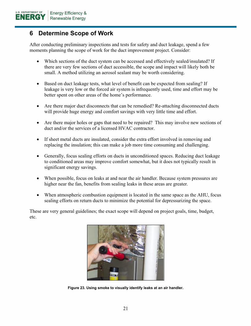
These are very general guidelines; the exact scope will depend on project goals, time, budget, etc.
Figure 23. Using smoke to visually identify leaks at an air handler.
22
7 Duct Sealing Procedure
7.1 How to Apply Mastic The most common complaints about duct mastic are that it is inconvenient or messy to install. With experience, using mastic does not need to be either; sealing with mastic can often be accomplished more quickly and with greater effect than with tapes.
Refer to manufacturer’s literature for the proper temperatures to apply mastic; some should not be used in very cold conditions. Before applying mastic, duct surfaces should be relatively clean. While some contractors report that cleaning ducts is less critical for mastics than for tapes, most mastic manufacturer instructions state surfaces must be free of dirt, dust, grease, water, corrosion, etc. While meticulously washing and drying all ducts before sealing may be impractical, some duct systems can be tremendously dusty and dirty. In such cases, it is important to remove much of this grime by wiping or vacuuming.
Mastic is available in pails of various volumes as well as in caulk tubes. Mastic manufacturers usually instruct users to apply mastic with brushes, trowels, or caulk guns. In the authors’ experience, applying by hand is often much cleaner, quicker, and more effective. Applying by hand (while wearing appropriate gloves) allows the duct sealer to feel the duct surfaces, seams, and gaps; this is especially important when the gaps are not visible—a very common occurrence.
Using proper gloves is key whether applying by hand or with tools. Be aware of screws and sharp edges. Gloves should protect from some of these risks while keeping hands free from mastic (or at least mostly free from mastic). Care should be taken to remove gloves before touching other surfaces. Once cured, mastic is very difficult to remove from surfaces, clothing, and skin.
Heavy-duty rubber gloves are one option, but these sometimes reduce dexterity and “feeling” capacity when applying mastic by hand. Thin, disposable rubber gloves (e.g. latex gloves), on the other hand, do not offer substantial protection from sharp edges. One compromise involves using inexpensive canvas gloves beneath disposable rubber gloves. The outer latex glove can be replaced when it is too dirty or becomes punctured or torn. The inner glove will last longer, but it can also be discarded when it becomes torn or embedded with mastic.
Another “trick” is to only use one hand to apply mastic. Using one hand—with the appropriate glove(s)—for mastic application will leave the other hand clean to move equipment, reach for tools, crawl through tight spaces, etc. Having one clean hand can keep equipment and job sites much cleaner.
While mastic alone can work well to cover small seams, larger gaps and joints may require mesh tape to reinforce the mastic. Generally, this involves spreading a layer of mastic near the gap, applying mesh tape, and then covering the tape with another layer of mastic. Larger gaps of approximately one inch or more are usually too large for tape and may require patches using sheet metal, duct board, or other approved material.
23
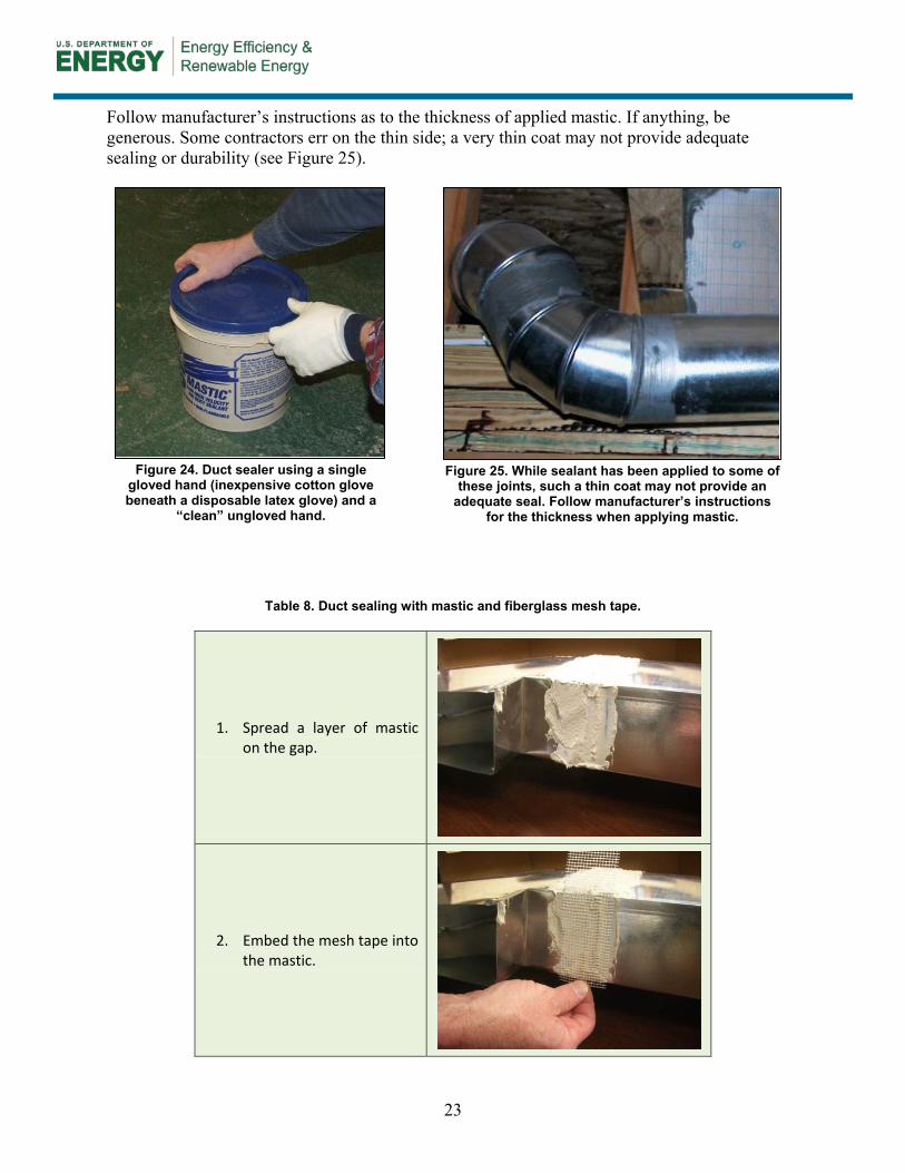
Follow manufacturer’s instructions as to the thickness of applied mastic. If anything, be generous. Some contractors err on the thin side; a very thin coat may not provide adequate sealing or durability (see Figure 25).
Table 8. Duct sealing with mastic and fiberglass mesh tape.
1. Spread a layer of mastic on the gap.
2. Embed the mesh tape into the mastic.
Figure 24. Duct sealer using a single gloved hand (inexpensive cotton glove beneath a disposable latex glove) and a
“clean” ungloved hand.
Figure 25. While sealant has been applied to some of these joints, such a thin coat may not provide an
adequate seal. Follow manufacturer’s instructions for the thickness when applying mastic.
24
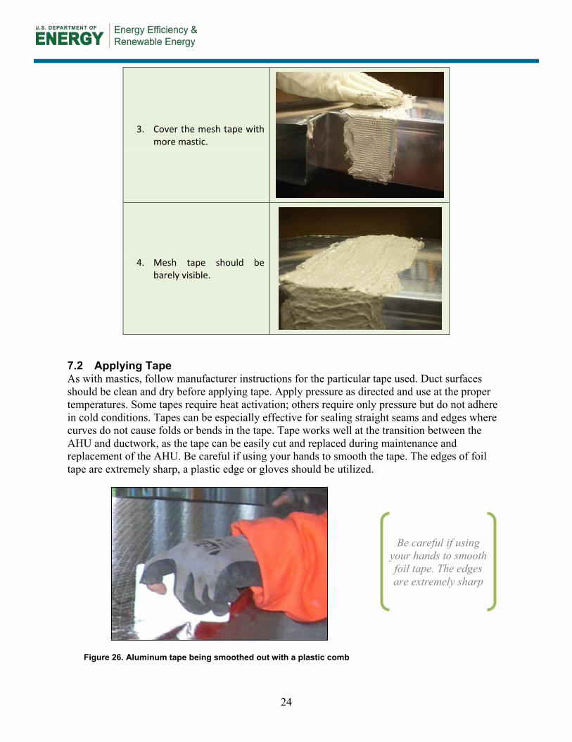
3. Cover the mesh tape with more mastic.
4. Mesh tape should be barely visible.
7.2 Applying Tape As with mastics, follow manufacturer instructions for the particular tape used. Duct surfaces should be clean and dry before applying tape. Apply pressure as directed and use at the proper temperatures. Some tapes require heat activation; others require only pressure but do not adhere in cold conditions. Tapes can be especially effective for sealing straight seams and edges where curves do not cause folds or bends in the tape. Tape works well at the transition between the AHU and ductwork, as the tape can be easily cut and replaced during maintenance and replacement of the AHU. Be careful if using your hands to smooth the tape. The edges of foil tape are extremely sharp, a plastic edge or gloves should be utilized.
Figure 26. Aluminum tape being smoothed out with a plastic comb
Be careful if using your hands to smooth foil tape. The edges are extremely sharp
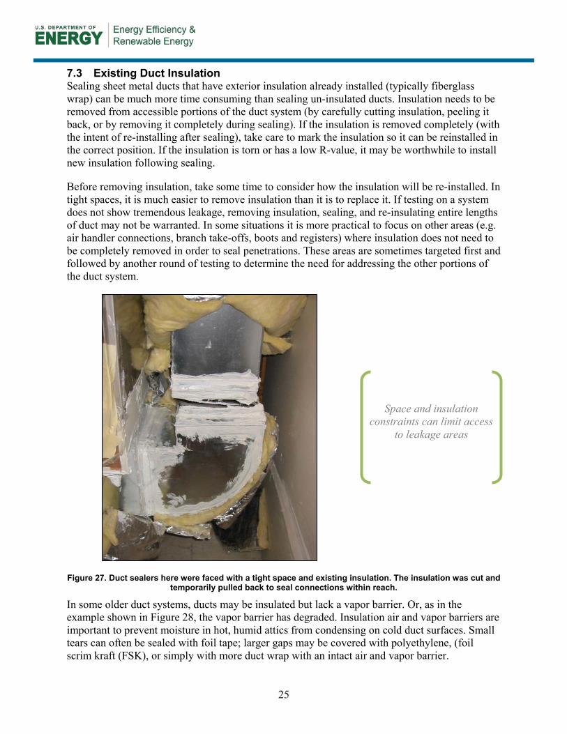
25
7.3 Existing Duct Insulation Sealing sheet metal ducts that have exterior insulation already installed (typically fiberglass wrap) can be much more time consuming than sealing un-insulated ducts. Insulation needs to be removed from accessible portions of the duct system (by carefully cutting insulation, peeling it back, or by removing it completely during sealing). If the insulation is removed completely (with the intent of re-installing after sealing), take care to mark the insulation so it can be reinstalled in the correct position. If the insulation is torn or has a low R-value, it may be worthwhile to install new insulation following sealing.
Before removing insulation, take some time to consider how the insulation will be re-installed. In tight spaces, it is much easier to remove insulation than it is to replace it. If testing on a system does not show tremendous leakage, removing insulation, sealing, and re-insulating entire lengths of duct may not be warranted. In some situations it is more practical to focus on other areas (e.g. air handler connections, branch take-offs, boots and registers) where insulation does not need to be completely removed in order to seal penetrations. These areas are sometimes targeted first and followed by another round of testing to determine the need for addressing the other portions of the duct system.
Figure 27. Duct sealers here were faced with a tight space and existing insulation. The insulation was cut and temporarily pulled back to seal connections within reach.
In some older duct systems, ducts may be insulated but lack a vapor barrier. Or, as in the example shown in Figure 28, the vapor barrier has degraded. Insulation air and vapor barriers are important to prevent moisture in hot, humid attics from condensing on cold duct surfaces. Small tears can often be sealed with foil tape; larger gaps may be covered with polyethylene, (foil scrim kraft (FSK), or simply with more duct wrap with an intact air and vapor barrier.
Space and insulation
constraints can limit access to leakage areas
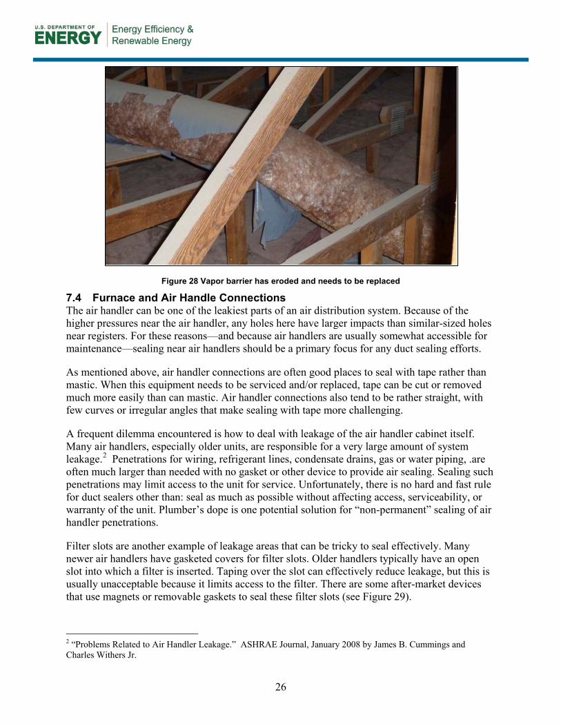
26
Figure 28 Vapor barrier has eroded and needs to be replaced
7.4 Furnace and Air Handle Connections The air handler can be one of the leakiest parts of an air distribution system. Because of the higher pressures near the air handler, any holes here have larger impacts than similar-sized holes near registers. For these reasons—and because air handlers are usually somewhat accessible for maintenance—sealing near air handlers should be a primary focus for any duct sealing efforts.
As mentioned above, air handler connections are often good places to seal with tape rather than mastic. When this equipment needs to be serviced and/or replaced, tape can be cut or removed much more easily than can mastic. Air handler connections also tend to be rather straight, with few curves or irregular angles that make sealing with tape more challenging.
A frequent dilemma encountered is how to deal with leakage of the air handler cabinet itself. Many air handlers, especially older units, are responsible for a very large amount of system leakage.2
Filter slots are another example of leakage areas that can be tricky to seal effectively. Many newer air handlers have gasketed covers for filter slots. Older handlers typically have an open slot into which a filter is inserted. Taping over the slot can effectively reduce leakage, but this is usually unacceptable because it limits access to the filter. There are some after-market devices that use magnets or removable gaskets to seal these filter slots (see
Penetrations for wiring, refrigerant lines, condensate drains, gas or water piping, .are often much larger than needed with no gasket or other device to provide air sealing. Sealing such penetrations may limit access to the unit for service. Unfortunately, there is no hard and fast rule for duct sealers other than: seal as much as possible without affecting access, serviceability, or warranty of the unit. Plumber’s dope is one potential solution for “non-permanent” sealing of air handler penetrations.
Figure 29).
2 “Problems Related to Air Handler Leakage.” ASHRAE Journal, January 2008 by James B. Cummings and Charles Withers Jr.
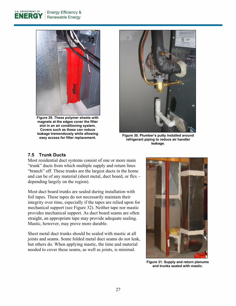
27
7.5 Trunk Ducts Most residential duct systems consist of one or more main “trunk” ducts from which multiple supply and return lines “branch” off. These trunks are the largest ducts in the home and can be of any material (sheet metal, duct board, or flex – depending largely on the region).
Most duct board trunks are sealed during installation with foil tapes. These tapes do not necessarily maintain their integrity over time, especially if the tapes are relied upon for mechanical support (see Figure 32). Neither tape nor mastic provides mechanical support. As duct board seams are often straight, an appropriate tape may provide adequate sealing. Mastic, however, may prove more durable.
Sheet metal duct trunks should be sealed with mastic at all joints and seams. Some folded metal duct seams do not leak, but others do. When applying mastic, the time and material needed to cover these seams, as well as joints, is minimal.
Figure 29. These polymer sheets with magnets at the edges cover the filter
slot in an air conditioning system. Covers such as these can reduce
leakage tremendously while allowing easy access for filter replacement. Figure 30. Plumber’s putty installed around
refrigerant piping to reduce air handler leakage.
Figure 31. Supply and return plenums and trunks sealed with mastic.
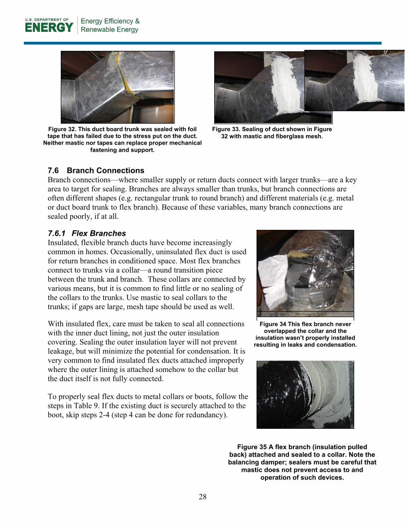
28
7.6 Branch Connections Branch connections—where smaller supply or return ducts connect with larger trunks—are a key area to target for sealing. Branches are always smaller than trunks, but branch connections are often different shapes (e.g. rectangular trunk to round branch) and different materials (e.g. metal or duct board trunk to flex branch). Because of these variables, many branch connections are sealed poorly, if at all.
7.6.1 Flex Branches Insulated, flexible branch ducts have become increasingly common in homes. Occasionally, uninsulated flex duct is used for return branches in conditioned space. Most flex branches connect to trunks via a collar—a round transition piece between the trunk and branch. These collars are connected by various means, but it is common to find little or no sealing of the collars to the trunks. Use mastic to seal collars to the trunks; if gaps are large, mesh tape should be used as well.
With insulated flex, care must be taken to seal all connections with the inner duct lining, not just the outer insulation covering. Sealing the outer insulation layer will not prevent leakage, but will minimize the potential for condensation. It is very common to find insulated flex ducts attached improperly where the outer lining is attached somehow to the collar but the duct itself is not fully connected.
To properly seal flex ducts to metal collars or boots, follow the steps in Table 9. If the existing duct is securely attached to the boot, skip steps 2-4 (step 4 can be done for redundancy).
Figure 32. This duct board trunk was sealed with foil tape that has failed due to the stress put on the duct.
Neither mastic nor tapes can replace proper mechanical fastening and support.
Figure 33. Sealing of duct shown in Figure 32 with mastic and fiberglass mesh.
Figure 34 This flex branch never overlapped the collar and the
insulation wasn’t properly installed resulting in leaks and condensation.
Figure 35 A flex branch (insulation pulled back) attached and sealed to a collar. Note the balancing damper; sealers must be careful that
mastic does not prevent access to and operation of such devices.
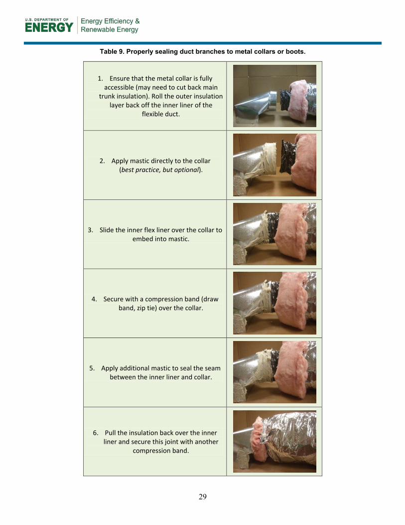
29
Table 9. Properly sealing duct branches to metal collars or boots.
1. Ensure that the metal collar is fully accessible (may need to cut back main
trunk insulation). Roll the outer insulation layer back off the inner liner of the
flexible duct.
2. Apply mastic directly to the collar (best practice, but optional).
3. Slide the inner flex liner over the collar to embed into mastic.
4. Secure with a compression band (draw band, zip tie) over the collar.
5. Apply additional mastic to seal the seam between the inner liner and collar.
6. Pull the insulation back over the inner liner and secure this joint with another
compression band.
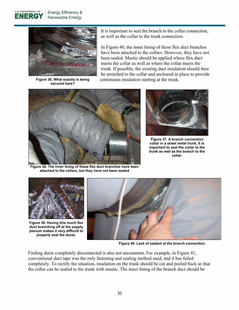
30
It is important to seal the branch to the collar connection, as well as the collar to the trunk connection. In Figure 40, the inner lining of these flex duct branches have been attached to the collars. However, they have not been sealed. Mastic should be applied where flex duct meets the collar as well as where the collar meets the trunk. If possible, the existing duct insulation should then be stretched to the collar and anchored in place to provide continuous insulation starting at the trunk.
Finding ducts completely disconnected is also not uncommon. For example, in Figure 41, conventional duct tape was the only fastening and sealing method used, and it has failed completely. To rectify the situation, insulation on the trunk should be cut and peeled back so that the collar can be sealed to the trunk with mastic. The inner lining of the branch duct should be
Figure 36. What exactly is being secured here?
Figure 38. The inner lining of these flex duct branches have been attached to the collars, but they have not been sealed
Figure 37. A branch connection collar in a sheet metal trunk. It is important to seal the collar to the trunk as well as the branch to the
collar.
Figure 39. Having this much flex duct branching off at the supply plenum makes it very difficult to
properly seal the ducts.
Figure 40. Lack of sealant at the branch connection.
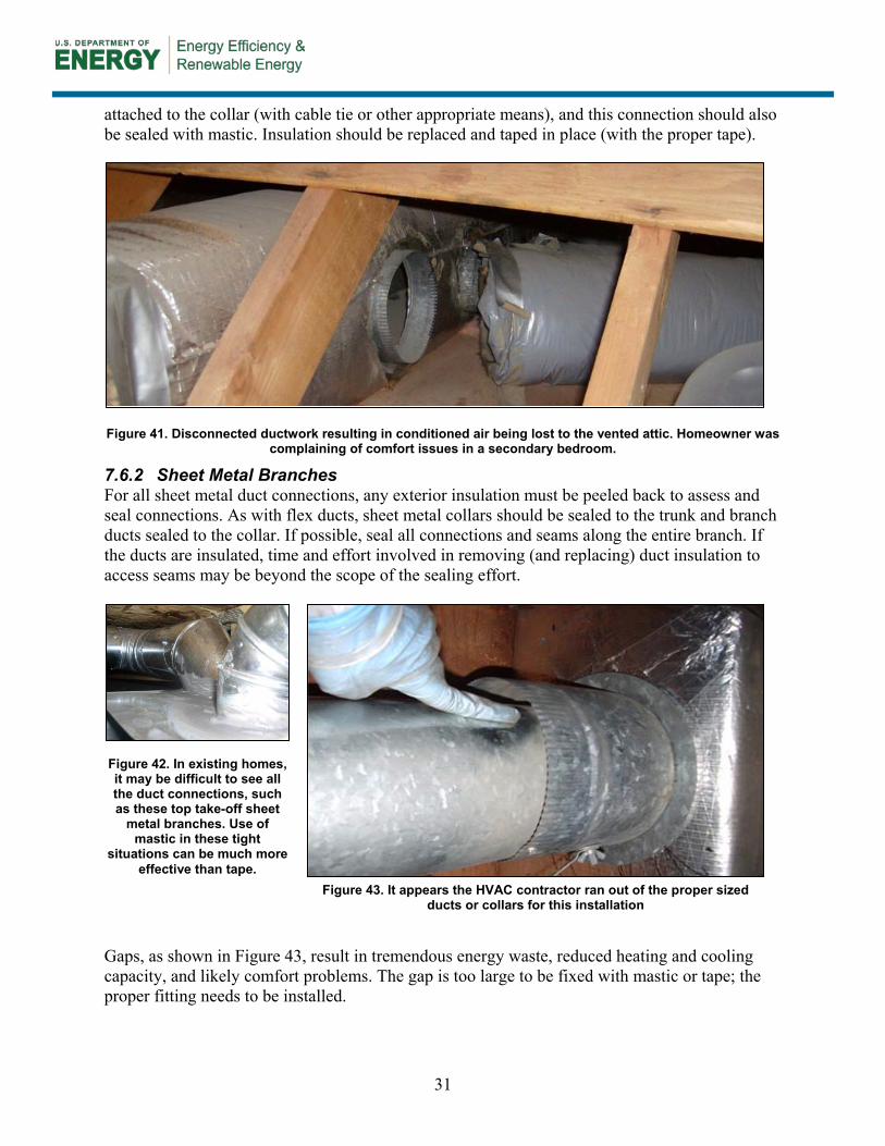
31
attached to the collar (with cable tie or other appropriate means), and this connection should also be sealed with mastic. Insulation should be replaced and taped in place (with the proper tape).
Figure 41. Disconnected ductwork resulting in conditioned air being lost to the vented attic. Homeowner was complaining of comfort issues in a secondary bedroom.
7.6.2 Sheet Metal Branches For all sheet metal duct connections, any exterior insulation must be peeled back to assess and seal connections. As with flex ducts, sheet metal collars should be sealed to the trunk and branch ducts sealed to the collar. If possible, seal all connections and seams along the entire branch. If the ducts are insulated, time and effort involved in removing (and replacing) duct insulation to access seams may be beyond the scope of the sealing effort.
Gaps, as shown in Figure 43, result in tremendous energy waste, reduced heating and cooling capacity, and likely comfort problems. The gap is too large to be fixed with mastic or tape; the proper fitting needs to be installed.
Figure 42. In existing homes, it may be difficult to see all the duct connections, such as these top take-off sheet
metal branches. Use of mastic in these tight
situations can be much more effective than tape.
Figure 43. It appears the HVAC contractor ran out of the proper sized ducts or collars for this installation
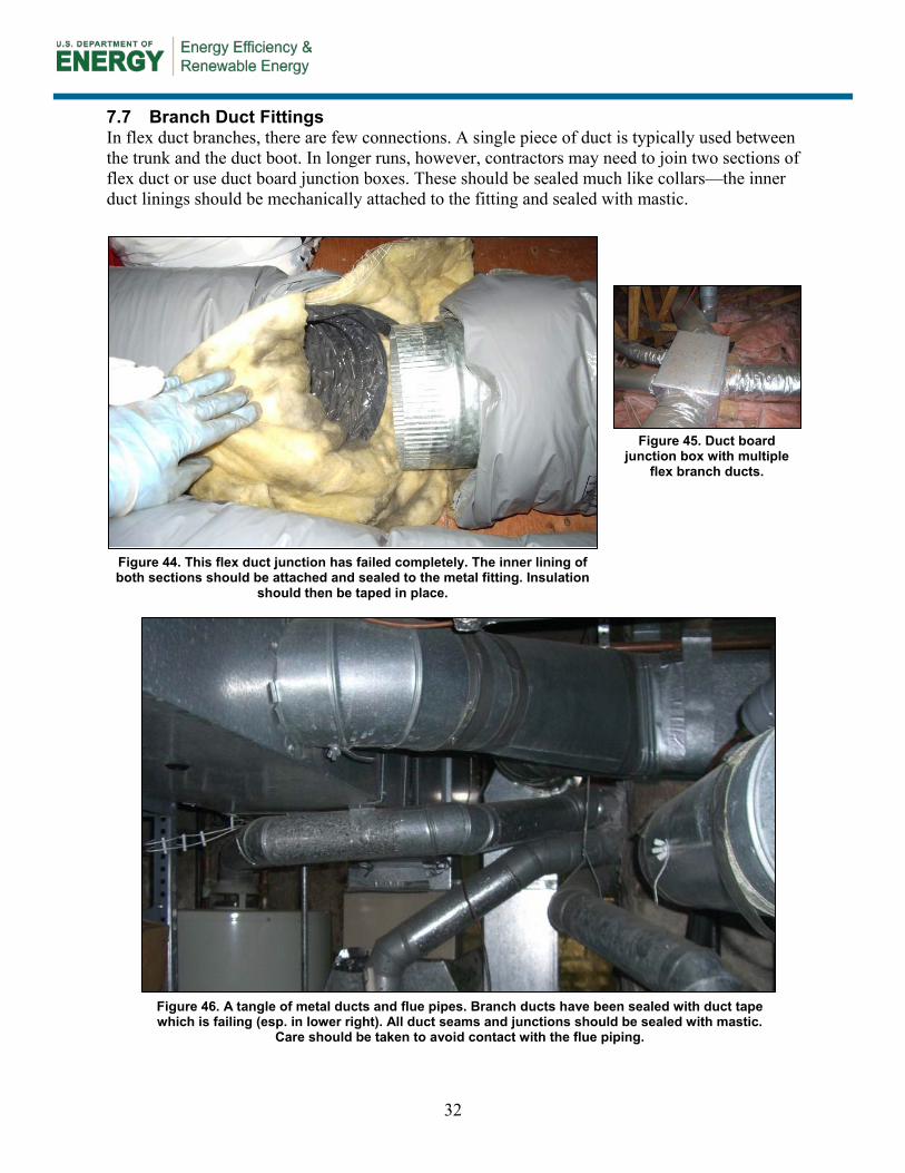
32
7.7 Branch Duct Fittings In flex duct branches, there are few connections. A single piece of duct is typically used between the trunk and the duct boot. In longer runs, however, contractors may need to join two sections of flex duct or use duct board junction boxes. These should be sealed much like collars—the inner duct linings should be mechanically attached to the fitting and sealed with mastic.
Figure 45. Duct board junction box with multiple
flex branch ducts.
Figure 44. This flex duct junction has failed completely. The inner lining of both sections should be attached and sealed to the metal fitting. Insulation
should then be taped in place.
Figure 46. A tangle of metal ducts and flue pipes. Branch ducts have been sealed with duct tape which is failing (esp. in lower right). All duct seams and junctions should be sealed with mastic.
Care should be taken to avoid contact with the flue piping.
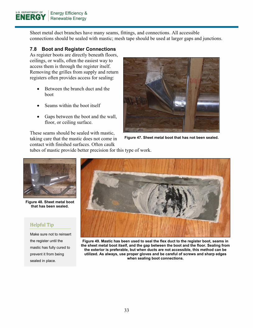
33
Sheet metal duct branches have many seams, fittings, and connections. All accessible connections should be sealed with mastic; mesh tape should be used at larger gaps and junctions.
7.8 Boot and Register Connections As register boots are directly beneath floors, ceilings, or walls, often the easiest way to access them is through the register itself. Removing the grilles from supply and return registers often provides access for sealing:
• Between the branch duct and the boot
• Seams within the boot itself
• Gaps between the boot and the wall, floor, or ceiling surface.
These seams should be sealed with mastic, taking care that the mastic does not come in contact with finished surfaces. Often caulk tubes of mastic provide better precision for this type of work.
Figure 47. Sheet metal boot that has not been sealed.
Helpful Tip
Make sure not to reinsert
the register until the
mastic has fully cured to
prevent it from being
sealed in place.
Figure 48. Sheet metal boot that has been sealed.
Figure 49. Mastic has been used to seal the flex duct to the register boot, seams in the sheet metal boot itself, and the gap between the boot and the floor. Sealing from
the exterior is preferable, but when ducts are not accessible, this method can be utilized. As always, use proper gloves and be careful of screws and sharp edges
when sealing boot connections.
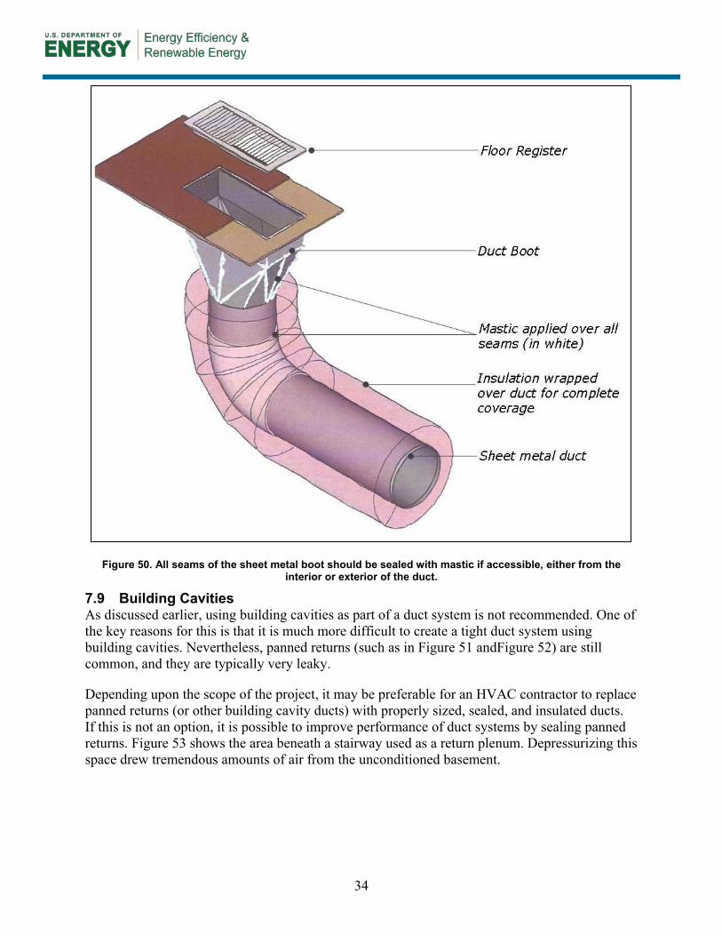
34
Figure 50. All seams of the sheet metal boot should be sealed with mastic if accessible, either from the interior or exterior of the duct.
7.9 Building Cavities As discussed earlier, using building cavities as part of a duct system is not recommended. One of the key reasons for this is that it is much more difficult to create a tight duct system using building cavities. Nevertheless, panned returns (such as in Figure 51 andFigure 52) are still common, and they are typically very leaky.
Depending upon the scope of the project, it may be preferable for an HVAC contractor to replace panned returns (or other building cavity ducts) with properly sized, sealed, and insulated ducts. If this is not an option, it is possible to improve performance of duct systems by sealing panned returns. Figure 53 shows the area beneath a stairway used as a return plenum. Depressurizing this space drew tremendous amounts of air from the unconditioned basement.

35
Figure 51. Floor joist bays used as panned returns.
Figure 52. Hard duct, panned returns, and wood blocking are combined as part of the return system. Gaps
and seams are not sealed at all, and wiring penetrations allow even more leakage.
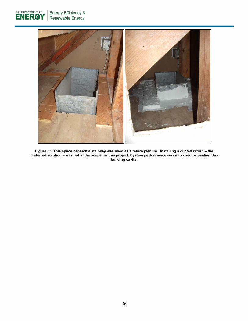
36
Figure 53. This space beneath a stairway was used as a return plenum. Installing a ducted return – the preferred solution – was not in the scope for this project. System performance was improved by sealing this
building cavity.
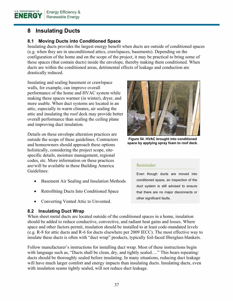
37
8 Insulating Ducts
8.1 Moving Ducts into Conditioned Space Insulating ducts provides the largest energy benefit when ducts are outside of conditioned spaces (e.g. when they are in unconditioned attics, crawlspaces, basements). Depending on the configuration of the home and on the scope of the project, it may be practical to bring some of these spaces (that contain ducts) inside the envelope, thereby making them conditioned. When ducts are within the conditioned areas, detrimental effects of leakage and conduction are drastically reduced.
Insulating and sealing basement or crawlspace walls, for example, can improve overall performance of the home and HVAC system while making these spaces warmer (in winter), dryer, and more usable. When duct systems are located in an attic, especially in warm climates, air sealing the attic and insulating the roof deck may provide better overall performance than sealing the ceiling plane and improving duct insulation.
Details on these envelope alteration practices are outside the scope of these guidelines. Contractors and homeowners should approach these options holistically, considering the project scope, site-specific details, moisture management, regional codes, etc. More information on these practices are/will be available in these Building America Guidelines:
• Basement Air Sealing and Insulation Methods
• Retrofitting Ducts Into Conditioned Space
• Converting Vented Attic to Unvented.
8.2 Insulating Duct Wrap When sheet metal ducts are located outside of the conditioned spaces in a home, insulation should be added to reduce conductive, convective, and radiant heat gains and losses. Where space and other factors permit, insulation should be installed to at least code-mandated levels (e.g. R-8 for attic ducts and R-6 for ducts elsewhere per 2009 IECC). The most effective way to insulate these ducts is often with “duct wrap” products, typically foil-faced fiberglass blankets.
Follow manufacturer’s instructions for installing duct wrap. Most of these instructions begin with language such as, “Ducts shall be clean, dry, and tightly sealed….” This bears repeating: ducts should be thoroughly sealed before insulating. In many situations, reducing duct leakage will have much larger comfort and energy impacts than insulating ducts. Insulating ducts, even with insulation seams tightly sealed, will not reduce duct leakage.
Figure 54. HVAC brought into conditioned space by applying spray foam to roof deck.
Reminder
Even though ducts are moved into
conditioned space, an inspection of the
duct system is still advised to ensure
that there are no major disconnects or
other significant faults.
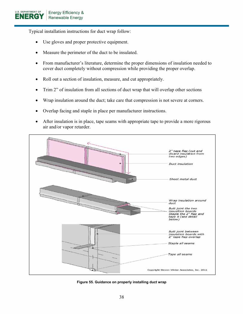
38
Typical installation instructions for duct wrap follow:
• Use gloves and proper protective equipment.
• Measure the perimeter of the duct to be insulated.
• From manufacturer’s literature, determine the proper dimensions of insulation needed to cover duct completely without compression while providing the proper overlap.
• Roll out a section of insulation, measure, and cut appropriately.
• Trim 2” of insulation from all sections of duct wrap that will overlap other sections
• Wrap insulation around the duct; take care that compression is not severe at corners.
• Overlap facing and staple in place per manufacturer instructions.
• After insulation is in place, tape seams with appropriate tape to provide a more rigorous air and/or vapor retarder.
Figure 55. Guidance on properly installing duct wrap
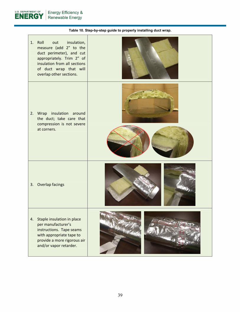
39
Table 10. Step-by-step guide to properly installing duct wrap.
1. Roll out insulation, measure (add 2” to the duct perimeter), and cut appropriately. Trim 2” of insulation from all sections of duct wrap that will overlap other sections.
2. Wrap insulation around the duct; take care that compression is not severe at corners.
3. Overlap facings
4. Staple insulation in place per manufacturer’s instructions. Tape seams with appropriate tape to provide a more rigorous air and/or vapor retarder.
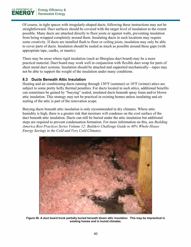
40
Of course, in tight spaces with irregularly-shaped ducts, following these instructions may not be straightforward. Duct surfaces should be covered with the target level of insulation to the extent possible. Many ducts are attached directly to floor joists or against walls, preventing insulation from being wrapped completely around them. Insulating ducts in such locations may require some creativity. If ducts are installed flush to floor or ceiling joists, insulation may only be able to cover parts of ducts. Insulation should be sealed as much as possible around these gaps (with appropriate tape, caulks, or mastic).
There may be areas where rigid insulation (such as fiberglass duct board) may be a more practical material. Duct board may work well in conjunction with flexible duct wrap for parts of sheet metal duct systems. Insulation should be attached and supported mechanically—tapes may not be able to support the weight of the insulation under many conditions.
8.3 Ducts Beneath Attic Insulation Heating and air conditioning ducts running through 130°F (summer) or 10°F (winter) attics are subject to some pretty hefty thermal penalties. For ducts located in such attics, additional benefits can sometimes be gained by “burying” sealed, insulated ducts beneath spray foam and/or blown attic insulation. This strategy may not be practical in existing homes unless insulating and air sealing of the attic is part of the renovation scope.
Burying ducts beneath attic insulation is only recommended in dry climates. Where attic humidity is high, there is a greater risk that moisture will condense on the cool surface of the duct beneath attic insulation. Ducts can still be buried under the attic insulation but additional steps are required to prevent condensation formation. For more information on this, see Building America Best Practices Series Volume 12: Builders Challenge Guide to 40% Whole-House Energy Savings in the Cold and Very Cold Climates.
Figure 56. A duct board trunk partially buried beneath blown attic insulation. This may be impractical in
existing homes and in humid climates.
41
9 Testing Out
Initial testing (“testing in”) is important to make sure the home is safe, the systems are in working order, and that sealing will likely not cause any detriment to performance. Testing after the work is complete is also important to verify that systems are in safe, working order after sealing has been performed.
9.1 Duct Leakage Tests While duct leakage tests are not necessary to assess safety, the tests are useful to gauge impacts of the duct sealing efforts. Duct leakage reductions are required by some programs, and testing duct leakage (both before and after) is one of the best ways for duct sealers to gain experience in the most effective duct sealing practices.
9.2 Airflow Duct sealing can result in lower air flow across the heat exchangers. Repeat initial tests to see if airflow is still in an acceptable range. If air flow is too low, HVAC contractors may need to reconfigure the system to avoid coil freezing or damaging equipment. Depending on the project, fixes may include increasing the size of ducts to reduce pressure drop; or installing properly-sized, smaller-capacity equipment.
9.3 Combustion Safety Because duct sealing can change the pressure patterns in a home, it’s important to repeat combustion safety tests. If tests fail, the combustion problem must be remedied by a qualified contractor. Remedies may include providing outside air for combustion, or replacing appliances with sealed-combustion.
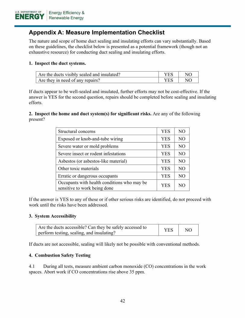
42
Appendix A: Measure Implementation Checklist The nature and scope of home duct sealing and insulating efforts can vary substantially. Based on these guidelines, the checklist below is presented as a potential framework (though not an exhaustive resource) for conducting duct sealing and insulating efforts. 1. Inspect the duct systems.
Are the ducts visibly sealed and insulated? YES NO Are they in need of any repairs? YES NO
If ducts appear to be well-sealed and insulated, further efforts may not be cost-effective. If the answer is YES for the second question, repairs should be completed before sealing and insulating efforts. 2. Inspect the home and duct system(s) for significant risks. Are any of the following present?
Structural concerns YES NO Exposed or knob-and-tube wiring YES NO Severe water or mold problems YES NO Severe insect or rodent infestations YES NO Asbestos (or asbestos-like material) YES NO Other toxic materials YES NO Erratic or dangerous occupants YES NO Occupants with health conditions who may be sensitive to work being done YES NO
If the answer is YES to any of these or if other serious risks are identified, do not proceed with work until the risks have been addressed. 3. System Accessibility
Are the ducts accessible? Can they be safely accessed to perform testing, sealing, and insulating? YES NO
If ducts are not accessible, sealing will likely not be possible with conventional methods. 4. Combustion Safety Testing 4.1 During all tests, measure ambient carbon monoxide (CO) concentrations in the work spaces. Abort work if CO concentrations rise above 35 ppm.
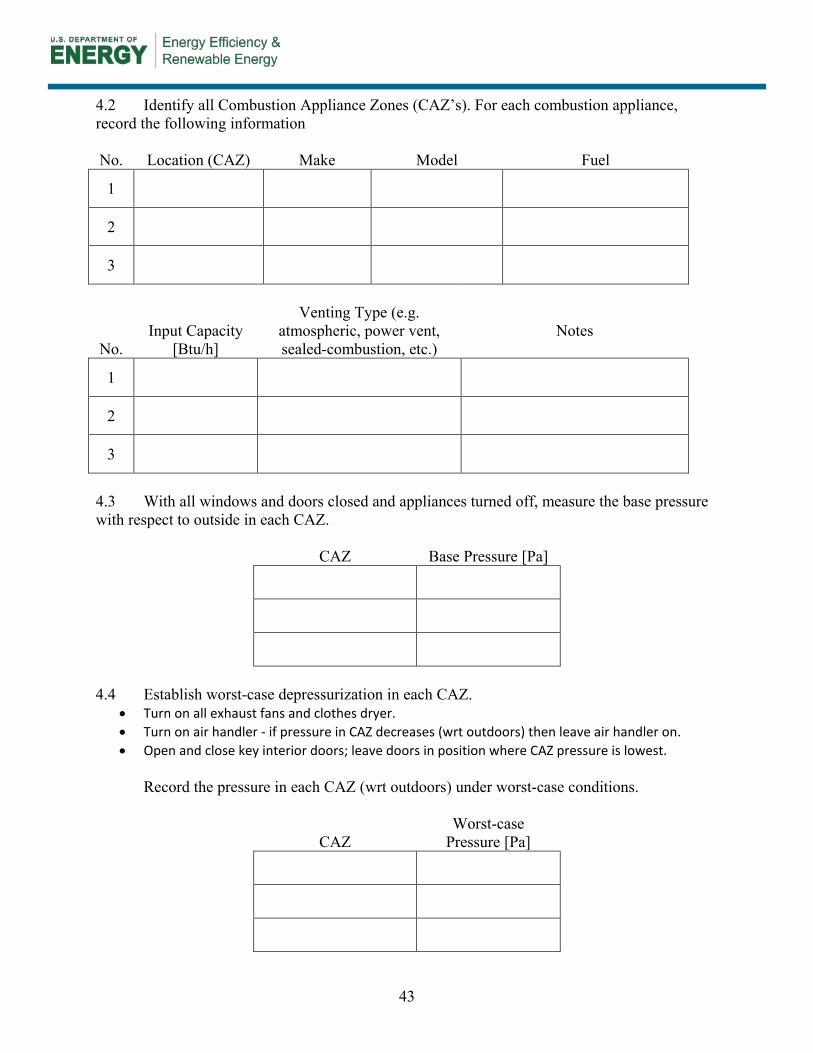
43
4.2 Identify all Combustion Appliance Zones (CAZ’s). For each combustion appliance, record the following information No. Location (CAZ) Make Model Fuel
1
2
3
No. Input Capacity
[Btu/h]
Venting Type (e.g.
atmospheric, power vent, sealed-combustion, etc.)
Notes
1
2
3
4.3 With all windows and doors closed and appliances turned off, measure the base pressure with respect to outside in each CAZ.
CAZ Base Pressure [Pa]
4.4 Establish worst-case depressurization in each CAZ.
• Turn on all exhaust fans and clothes dryer. • Turn on air handler - if pressure in CAZ decreases (wrt outdoors) then leave air handler on. • Open and close key interior doors; leave doors in position where CAZ pressure is lowest.
Record the pressure in each CAZ (wrt outdoors) under worst-case conditions.
CAZ Worst-case
Pressure [Pa]
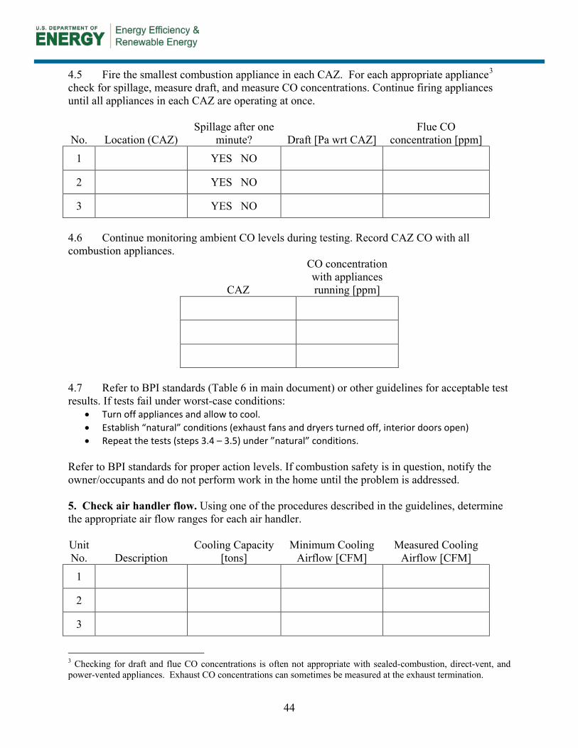
44
4.5 Fire the smallest combustion appliance in each CAZ. For each appropriate appliance3
check for spillage, measure draft, and measure CO concentrations. Continue firing appliances until all appliances in each CAZ are operating at once.
No. Location (CAZ) Spillage after one
minute? Draft [Pa wrt CAZ] Flue CO
concentration [ppm]
1 YES NO
2 YES NO
3 YES NO
4.6 Continue monitoring ambient CO levels during testing. Record CAZ CO with all combustion appliances.
CAZ
CO concentration with appliances running [ppm]
4.7 Refer to BPI standards (Table 6 in main document) or other guidelines for acceptable test results. If tests fail under worst-case conditions:
• Turn off appliances and allow to cool. • Establish “natural” conditions (exhaust fans and dryers turned off, interior doors open) • Repeat the tests (steps 3.4 – 3.5) under ”natural” conditions.
Refer to BPI standards for proper action levels. If combustion safety is in question, notify the owner/occupants and do not perform work in the home until the problem is addressed. 5. Check air handler flow. Using one of the procedures described in the guidelines, determine the appropriate air flow ranges for each air handler. Unit No. Description
Cooling Capacity [tons]
Minimum Cooling Airflow [CFM]
Measured Cooling Airflow [CFM]
1
2
3
3 Checking for draft and flue CO concentrations is often not appropriate with sealed-combustion, direct-vent, and power-vented appliances. Exhaust CO concentrations can sometimes be measured at the exhaust termination.
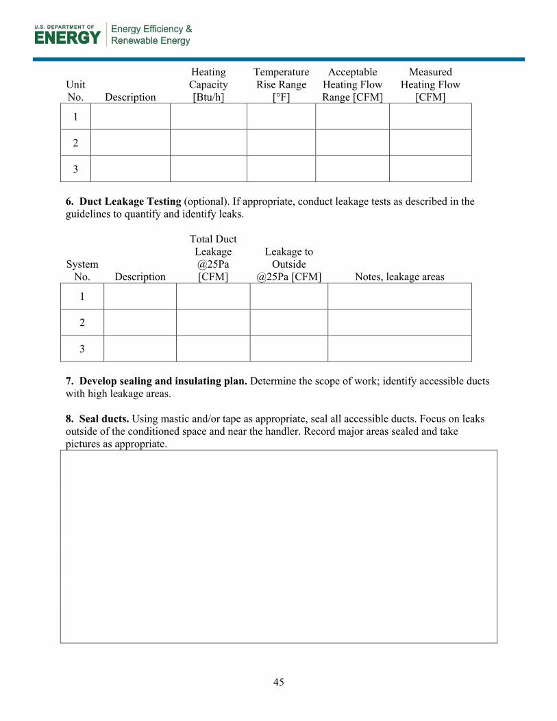
45
Unit No. Description
Heating Capacity [Btu/h]
Temperature Rise Range
[°F]
Acceptable Heating Flow Range [CFM]
Measured Heating Flow
[CFM]
1
2
3
6. Duct Leakage Testing (optional). If appropriate, conduct leakage tests as described in the guidelines to quantify and identify leaks.
System No. Description
Total Duct Leakage @25Pa [CFM]
Leakage to Outside
@25Pa [CFM] Notes, leakage areas
1
2
3
7. Develop sealing and insulating plan. Determine the scope of work; identify accessible ducts with high leakage areas. 8. Seal ducts. Using mastic and/or tape as appropriate, seal all accessible ducts. Focus on leaks outside of the conditioned space and near the handler. Record major areas sealed and take pictures as appropriate.
46
9. Insulate ducts. When mastic has set, insulate accessible, uninsulated ducts as appropriate. Focus insulation efforts on ducts outside the conditioned space. Record insulation installed and/or take pictures as appropriate. 10. Test out. Repeat combustion safety tests (step 3) and airflow tests (step 4) to assure safe operation. Conduct duct leakage test if appropriate (step 5).
47
Appendix B: Material Specification Mastic. Air duct sealant for permanently sealing fabricated joints and seams of HVAC air ducts and thermal insulation.
Required Certification: Water-based duct sealant – UL 181A-M and/or UL 181B-M (depending on duct system type)
Additional Certification: Meets all SMACNA seal and pressure classes. Relevant Test Methods: ASTM R-96, ASTM D-1310, ASTM E-84, ASTM C-731, ASTM D-2202, ASTM C-732
Aluminum and/or Butyl Tape. Air duct tape for permanently sealing fabricated joints and seams of HVAC air ducts and thermal insulation. All pressure-sensitive tapes used in the manufacture of rigid fiberglass ducts shall be UL 181A listed and UL 181B for flexible ducts.
Required Certification: UL 181A-P, UL 181B-FX Relevant Test Methods: ASTM D3330, ASTM D882, AAMA 809.2, ASTM E-96, ASTM
C711-72, ASTM C763-73 Duct Wrap Insulation. Thermally insulated fiberglass batt material that reduces unwanted heat loss or gain and condensation during system operation.
Required Code Requirements: Meet IRC/IECC insulation requirements for climate. Relevant Test Methods: ASTM C1290, ASTM C177, ASTM C518, ASTM C976
Closed Cell Spray Polyurethane Foam. Non-structural thermal insulating material that can be spray applied.
Required Code Requirements: IRC - foam plastic, complies with NFPA Standards 286 Relevant Test Methods: ASTM C518, ASTM E84, ASTM E119
Flexible Duct. Thermally insulated, fully lined, flexible air duct designed for use in HVAC distribution systems.
Required Certification: UL 181, complies with NFPA Standards 90A and 90B Additional Certification: ADC-Certified R-values
Duct Board. Resin-bonded fiberglass formed into rigid rectangular boards faced on exterior with a fire-resistant foil-scrim kraft vapor retarder and faced on the interior with a tightly bonded non-woven mat.
Required Certification: UL 181, complies with NFPA Standards 90A and 90B Relevant Test Methods: ASTM C 1136, ASTM G21, ASTM G22
Sheet Metal Duct. Fabricated ductwork from galvanized steel sheets. Duct systems shall include UL 181 listed ducts with approved closure systems including collars, connections and splices.
Required Certification: UL 181 Relevant Test Methods: ASTM A653
Drawbands/Compression Band. Adjustable length stainless-steel worm-drive hose clamps or uv-resistant nylon duct ties used to secure flexible ductwork to sheet metal collars. Using an adjustable tensioning tool per manufacturer specifications is recommended.
Required Certification: UL 181A and a minimum tensile strength rating of 50 pounds
48
References [2009 IECC] International Code Council. (2009). International Energy Conservation Code. Washington, DC: International Code Council. [2009 IRC] International Code Council. (2009). International Residential Code. Washington, DC: International Code Council. Air Conditioning Contractors of America. (2010). HVAC Quality Installation Specification. Arlington, VA: Air Conditioning Contractors of America. https://www.acca.org/Files/?id=693. Accessed April 8, 2011. [ASTM] American Society for Testing and Materials. (2007). ASTM E1554 -07, Standard Test Methods for Determining Air Leakage of Air Distribution Systems by Fan Pressurization. West Conshohocken, PA: American Society for Testing and Materials. [BPI] Building Performance Institute. (2005). Technical Standards for the Building Analyst Professional. Malta, NY: Building Performance Institute. http://www.bpi.org/Web Download/BPI Standards/Building Analyst Professional_2-28-05nNC-newCO.pdf. Accessed April 8, 2011. Building Technologies Program, Office of Energy Efficiency and Renewable Energy, U.S. Department of Energy. (2003). “Air Distribution System Installation and Sealing. Building Technologies Program.” DOE/GO102003-0783, Office of Energy Efficiency and Renewable Energy, U.S. Department of Energy. http://www.toolbase.org/PDF/DesignGuides/doe_airdistributionsysteminstallation.pdf. Accessed April 8, 2011. [CARB] Consortium for Advanced Residential Buildings. “Retrofitting America: A 1970s Home Energy Efficiency Analysis”. http://www.carb-swa.com/articles/homepage/RetrofittingAmerica_1970sHomeAnalysis.pdf. Accessed April 8, 2011. [CEC] California Energy Commission. (2010). 2008 Building Energy Efficiency Standards: Residential Compliance Manual. Sacramento, CA: California Energy Commission. http://www.energy.ca.gov/2008publications/CEC-400-2008-016/CEC-400-2008-016-CMF-REV1.PDF. Accessed September 27, 2011. Cummings, J. B.; Withers, C. Jr. (January 2008). “Problems Related to Air Handler Leakage.” ASHRAE Journal. [Energy Conservatory] The Energy Conservatory. “Using a Pressure Pan to Diagnose Duct Leakage.” April 2010. http://www.energyconservatory.com/download/presspanuser.pdf. Accessed September 21, 2011. [EIA] Energy Information Administration. “Table US7: Unit Price by Fuels Used.” 2005 Residential Energy Consumption Survey: Energy Consumption and Expenditures Tables.
49
http://www.eia.doe.gov/emeu/recs/recs2005/c&e/summary/pdf/tableus7.pdf. Accessed April 6, 2011. Hohman, J. (2011). HVACR 301. Florence, KY: Delmar Cengage Learning. Holladay, Martin. “Sealing Ducts: What’s Better, Tape or Mastic?” Green Building Advisor. http://www.greenbuildingadvisor.com/book/export/html/17758 Accessed March 7, 2011. Moravek, J. (2009). HVACR 101. Florence, KY: Delmar Cengage Learning. Moravek, J.; Hohman J.E. (2010). HVACR 201. Florence, KY: Delmar Cengage Learning. [NREL Duct Insulation] National Renewable Energy Laboratory. “National Residential Efficiency Measures Database: Retrofit Measures for Duct Insulation.” National Renewable Energy Laboratory. http://www.nrel.gov/ap/retrofits/measures.cfm?gId=2&ctId=16 Accessed April 7, 2011. [NREL Duct Sealing] National Renewable Energy Laboratory. “National Residential Efficiency Measures Database: Retrofit Measures for Duct Sealing.” National Renewable Energy Laboratory. http://www.nrel.gov/ap/retrofits/measures.cfm?gId=2&ctId=17. (Accessed April 7, 2011). Rutkowski, H. (2006). Manual J Residential Load Calculation (Eighth Edition). Arlington, VA: Air Conditioning Contractors of America. Rutkowski, H. (2009). Manual D Residential Duct Systems (Third Edition). Arlington, VA: Air Conditioning Contractors of America. Sherman, M. H.; Walker, I.S.; Dickerhoff, D.J. (2000). “Stopping Duct Quacks: Longevity of Residential Duct Sealants.” Lawrence Berkeley National Laboratory, LBNL-45423. http://www.osti.gov/bridge/purl.cover.jsp;jsessionid=64967D09B341E3EC57F31C315262B1CB?purl=/776574-DXrFxa/native/. Accessed April 8, 2011. Silberstein, E. (2004). Residential Construction Academy: HVACR. Florence, KY: Delmar Cengage Learning. [SMACNA] Sheet Metal and Air Conditioning Contractors’ National Association. (1998). Residential Comfort System Installation Standards Manual. Chantilly, VA: Sheet Metal and Air Conditioning Contractors’ National Association, Inc. [UL 181A] Underwriters Laboratories. (2008). UL Standard 181A: Standard for Closure Systems for Use With Rigid Air Ducts. Camas, WA: Underwriters Laboratories. [UL 181B] Underwriters Laboratories. (2008). UL Standard 181B: Standard for Closure Systems for Use With Flexible Air Ducts and Air Connectors. Camas, WA: Underwriters Laboratories.
DOE/GO-102011-3474 ▪ December 2011
Printed with a renewable-source ink on paper containing at least 50% wastepaper, including 10% post-consumer waste.