Embed Size (px)
Citation preview
MEASUREMENT BASED EVALUATION OFLOW COMPLEXITY RECEIVERS FOR D-TXAA HSDPA
Christian Mehlfuhrer, Sebastian Caban, and Markus Rupp
Institute of Communications and Radio-Frequency EngineeringVienna University of Technology
Gusshausstrasse 25/389, A-1040 Vienna, AustriaEmail: {chmehl, scaban, mrupp}@nt.tuwien.ac.at
Web: http://www.nt.tuwien.ac.at/rapid-prototyping
ABSTRACTIn 2007, the 3GPP agreed to standardize D-TxAA (DualStream Transmit Antenna Array) as the MIMO ex-tension for HSDPA (High Speed Downlink Packet Ac-cess). In this work, we examine receiver structures forD-TxAA.
At a high SINR, D-TxAA operates in the dualstream mode, i.e. two independent data streams aretransmitted to one user simultaneously. In this mode,our receiver uses equalization and optional interferencecancelation. At a low SINR, D-TxAA operates in singlestream mode, in which several users can be served simul-taneously, and hence an interference aware equalizer isnecessary to achieve high performance. Utilizing thesereceiver structures, we measure the average throughputof D-TxAA in outdoor-to-indoor scenarios in the innercity of Vienna.
1. INTRODUCTION
In the last years, MIMO systems gained more and moreattention in standardization committees. Already backin 1999, a multiple transmit antenna option (requiringonly one receive antenna) was specified by the 3GPPfor UMTS. This so-called closed loop mode with trans-mit diversity (TxAA) [1] uses strongly quantized pre-coding at the transmitter to increase the SINR at theuser equipment. In 2007, the 3GPP standardized D-TxAA (Dual Stream Transmit Diversity) [2], the firsttrue MIMO extension in UMTS. D-TxAA is downwardcompatible to TxAA and equals TxAA when the SINRat the user equipment is low. At larger SINRs, D-TxAAswitches to dual stream mode and transmits two inde-pendently coded HSDPA (High Speed Downlink PacketAccess) [3] data streams. An important difference be-tween dual stream and single stream mode is that in thedual stream mode all 15 spreading codes of length 16 areassigned to a single user (the 16-th spreading code is re-quired for transmitting pilot and control information).In single stream mode, the Node B can serve multipleusers at the same time distinguished only by differentspreading codes. Therefore, in single stream mode theuser equipment receiver has to be aware of the interfer-ence generated by the data channels of other users.
The switching between single and dual stream mode,the encoding rate, and the modulation alphabet is de-termined by the CQI (Channel Quality Indicator) feed-back. Depending on the channel conditions and the typeof receiver implemented, the user equipment calculates
an appropriate CQI value in order to achieve a blockerror ratio of 10 % [1].
In this work, we investigate the performance of twolow-complexity receivers for D-TxAA by performingoutdoor-to-indoor measurements in the inner city of Vi-enna. For these measurements we utilize the ViennaMIMO testbed [4], capable of transmitting and receiv-ing arbitrary signals with 5 MHz bandwidth at 2.5 GHz.For comparison, we also measure the performance of thetwo SIMO systems transmitted from the first and secondtransmit antenna, respectively.
2. RECEIVER STRUCTURES
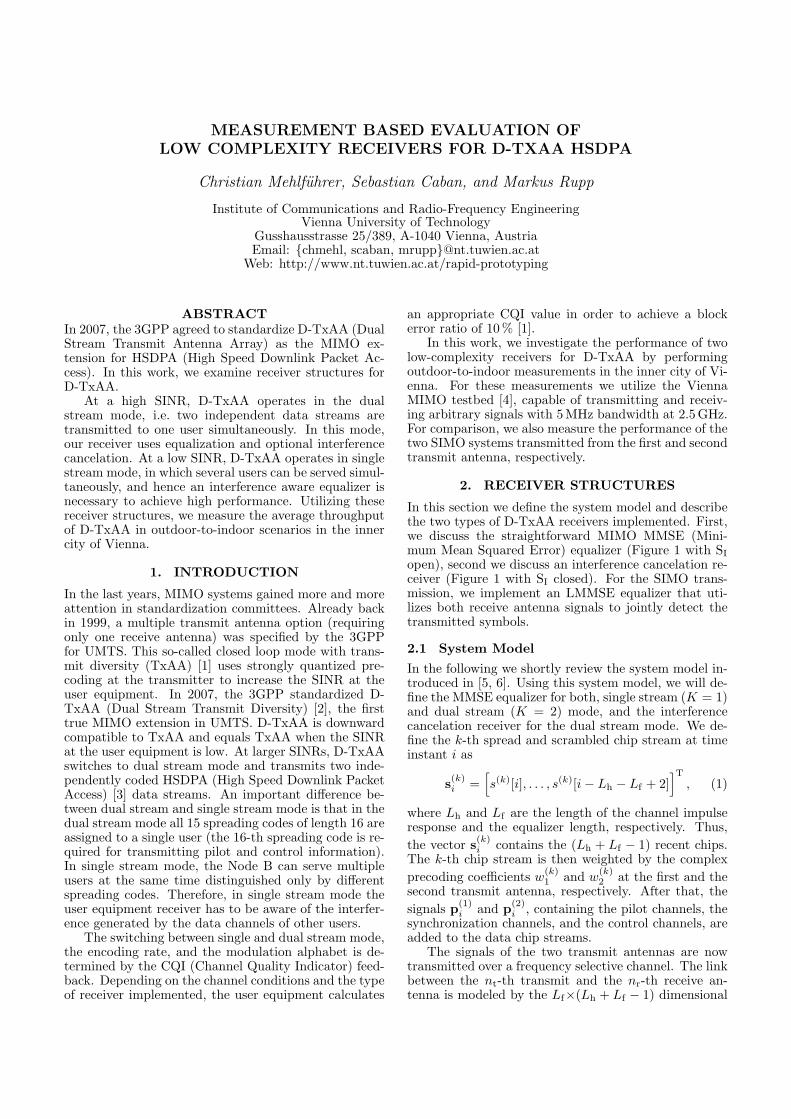
In this section we define the system model and describethe two types of D-TxAA receivers implemented. First,we discuss the straightforward MIMO MMSE (Mini-mum Mean Squared Error) equalizer (Figure 1 with SI
open), second we discuss an interference cancelation re-ceiver (Figure 1 with SI closed). For the SIMO trans-mission, we implement an LMMSE equalizer that uti-lizes both receive antenna signals to jointly detect thetransmitted symbols.
2.1 System Model
In the following we shortly review the system model in-troduced in [5, 6]. Using this system model, we will de-fine the MMSE equalizer for both, single stream (K = 1)and dual stream (K = 2) mode, and the interferencecancelation receiver for the dual stream mode. We de-fine the k-th spread and scrambled chip stream at timeinstant i as
s(k)i =
[s(k)[i], . . . , s(k)[i− Lh − Lf + 2]
]T
, (1)
where Lh and Lf are the length of the channel impulseresponse and the equalizer length, respectively. Thus,the vector s(k)
i contains the (Lh + Lf − 1) recent chips.The k-th chip stream is then weighted by the complexprecoding coefficients w
(k)1 and w
(k)2 at the first and the
second transmit antenna, respectively. After that, thesignals p(1)
i and p(2)i , containing the pilot channels, the
synchronization channels, and the control channels, areadded to the data chip streams.
The signals of the two transmit antennas are nowtransmitted over a frequency selective channel. The linkbetween the nt-th transmit and the nr-th receive an-tenna is modeled by the Lf×(Lh + Lf − 1) dimensional
dual stream mode
dual stream mode
SI
SI
Figure 1: D-TxAA receiver in single stream and dual stream mode, respectively. Interference cancelation is per-formed when the switch SI is closed. We assume without loss of generality that stream one is detected first.
band matrix
H(nr,nt) =
h
(nr,nt)0 . . . h
(nr,nt)Lh−1 0
. . . . . .0 h
(nr,nt)0 . . . h
(nr,nt)Lh−1
,
(2)where the h
(nr,nt)i represent the channel impulse re-
sponse of the nt-th transmit antenna to the nr-th receiveantenna. The entire frequency selective MIMO channelis modeled by a block matrix H consisting of NR×NT
(NT = 2 for TxAA) band matrices defined in (2).
H =
H(1,1) H(1,2)
......
H(NR,1) H(NR,2)
(3)
By stacking the received signal vectors of all NR receiveantennas
ri =[r(1)T
i , . . . , r(NR)Ti
]T
(4)
we can calculate the receive signal as
ri = H(W ⊗ ILh+Lf−1
)︸ ︷︷ ︸Hw
[s(1)i
s(2)i
]+ H
[p(1)
i
p(2)i
]+ vi.
(5)Here, ⊗ symbolizes the Kronecker product, the matrixW is the precoding matrix at the transmitter, and vi
is additive noise. If single stream transmission is per-formed, W1 is given by
W =
[w
(1)1 0
w(1)2 0
](6)
1Note that this matrix W can be slightly modified to alsoconsider the interference generated by the data streams of otherusers, thus making the MMSE equalizer to this system model aninterference aware equalizer. See [5] for more details.
and in the dual stream mode by
W =
[w
(1)1 w
(2)1
w(1)2 w
(2)2
]. (7)
2.2 MMSE Equalizer
By minimizing the quadratic error between the trans-mitted data chip stream and the equalized data chipstream, the MMSE equalizer is directly obtained fromthe system model in Equation (5). By assuming that thetransmitted data sequences and the noise are white, wecan calculate the equalizer filter coefficients [7, 8, 5, 6]as
f (k) =(HwHw
H +σ2
v
σ2s
I)−1
Hweτk,2(Lh+Lf−1). (8)
Here, f (k) =[f (1,k)T, . . . , f (NR,k)T
]Tdefines the NR
equalization filters (see also Figure 1) for the k-th datachip stream. The vector eτk,2(Lh+Lf−1) is a zero vectorof length 2(Lh + Lf − 1) with a single one at position
τk = τ + (k − 1)(Lh + Lf − 1) k = 1 . . .K. (9)
After applying the equalizer f (k) to the receive signal, weobtain an estimate s(k)
i−τ of the k-th data chip sequence.The variable τ specifies the delay of the equalized signaland has to fulfill τ ≥ Lh due to causality.
2.3 Interference Cancelation Receiver
The interference cancelation receiver is shown in Fig-ure 1 (switch SI closed). This receiver first cancels thedeterministic interference
p(nr)i = H
[p(1)
i
p(2)i
](10)
of the pilot and synchronization channels. After that,the data stream with larger post equalization SINR
t in ms
calculate CQI and precoding weights
19 24 1039374 123 ms11390 ms
read TX samplesfrom HDD
read TX samplesfrom HDD
write RX samples to HDD
testblock block
1stretrans-mission
2ndretrans-mission
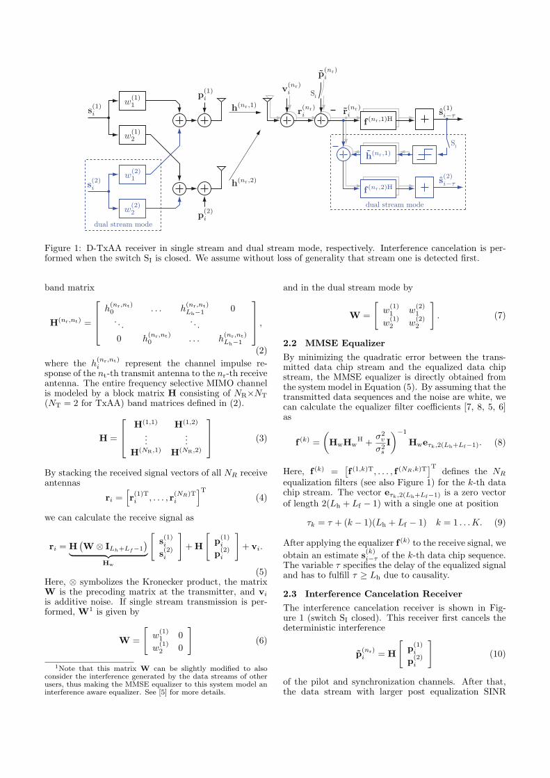
Figure 2: Testbed timing.
(see [6] for a detailed description on the calculationof this SINR) is equalized first2. The equalized chipstream is then descrambled, despread, and hard decidedto the nearest symbol constellation point. This recon-structed symbol stream is then again spread, scrambledand convoluted with the “virtual” channel h(nr,1) =w
(1)1 h(nr,1) + w
(1)2 h(nr,2). The virtual channel h(nr,1)
is given by the true channel coefficients and the precod-ing coefficients. The reconstructed interference can nowbe subtracted from the receive signal r(nr)
i and a secondequalizer yields the second data chip stream.
3. MEASUREMENT SETUP
For the measurements we utilize the Vienna MIMO test-bed, described in detail in [4] and [9]. As transmit anten-nas we used basestation antennas mounted 16 m aboverooftop. The receiver was placed at two different posi-tions indoors in the same building.
The feedback required by HSDPA for adapting thetransmit signal to the actual channel condition is imple-mented as follows.• At first, one HSDPA frame (the testblock) is trans-
mitted, see Figure 2, at time index 19 ms.• This HSDPA frame is then evaluated in a “mini-
receiver” which performs synchronization, receive fil-tering, channel and noise estimation, and an estima-tion of the post equalization SINR. The post equal-ization SINR is calculated for all four possible pre-coding vectors specified in D-TxAA. The SINR val-ues are then mapped to CQI values using an opti-mized CQI mapping table3. This method leads tofour CQI values (and corresponding transport blocksizes)—one for each possible precoding vector. Now,we select that precoding vector that corresponds tothe largest transport block size and thus the largestpotential throughput. The calculation of the CQIvalue and the precoding weight takes about 50 ms.
• The CQI value and the precoding weights are sig-nalled back to the transmitter of the testbed using aLAN connection.
• The transmitter then transmits an HSDPA subframethat was pre-generated and stored on a harddisk.This subframe has been encoded with the CQI value,and weighted by the precoding coefficients, signalledby the receiver. Since in HSDPA, HARQ (HybridAutomatic Retransmission Request) is immanent for
2In the following we assume without loss of generality that thefirst data chip stream has the larger SINR.
3The CQI mapping table was optimized to achieve about 10%block error ratio, as specified in the standard [10, Section 6A.2].
the system performance, we also transmit the firstand second retransmission with a delay of about10 ms. These three subframes are stored on a hard-disk at the receiver for later, off-line evaluation.
This procedure was carried out for a SIMO transmissionat the first transmit antenna, a SIMO transmission atthe second transmit antenna, and the MIMO D-TxAAtransmission4. These three transmissions were repeatedat 16 different transmit attenuator values leading to dif-ferent average receive SNRs. Averaging over small scalefading was achieved by repeating everything at 3840 re-ceive antenna positions, equally spaced distributed overan area of 4×4 λ.
4. MEASUREMENT RESULTS
The results presented in the following are evaluatedin terms of physical layer throughput. The “instanta-neous” throughput at one transmit attenuator value andone receive antenna position is calculated as
D =TBS
k · TTI. (11)
Here, TBS denotes the Transport Block Size, i.e. thenumber of bits transmitted in one HSDPA subframe.The TTI (Transmission Time Interval) here is chosenequal to 2ms. The value k corresponds to the num-ber of transmissions required for correctly receiving thissubframe. If the subframe is not received correctly af-ter two retransmissions (i.e. k = 3), the instantaneousthroughput is set to zero. The average throughput inone scenario is now calculated by averaging over all 3840receive antenna positions.
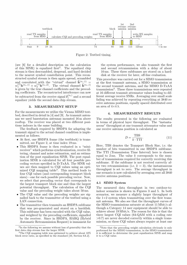
4.1 SIMO System
The measured data throughput in two outdoor-to-indoor scenarios is shown in Figures 3 and 5. In bothscenarios, we measure a slightly larger throughput ofthe 1×2 system when transmitting over the first trans-mit antenna. We also see that the throughput curves ofthe SIMO transmissions saturate at about 11 Mbit/s al-though a Category 14 user equipment should be able toachieve about 19 Mbit/s. The reason for this is that thethree largest CQI values (64-QAM with a coding rate>0.7) are never decoded correctly within a single trans-mission, so these CQI values always require at least one
4Note that the precoding weight calculation obviously is onlyperformed for the MIMO transmission, in the SIMO transmissionit is sufficient to determine the post equalization SINR and mapit to a CQI value.
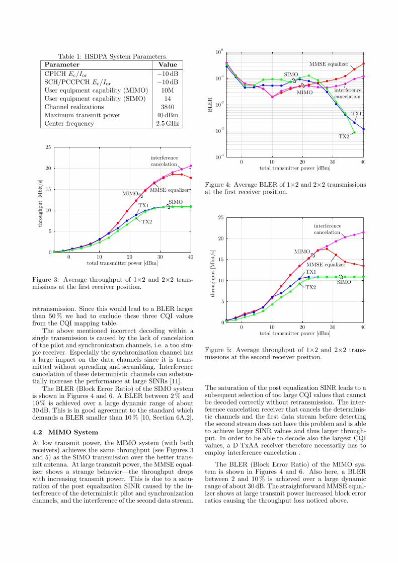
Table 1: HSDPA System Parameters.Parameter ValueCPICH Ec/Ior −10 dBSCH/PCCPCH Ec/Ior −10 dBUser equipment capability (MIMO) 10MUser equipment capability (SIMO) 14Channel realizations 3840Maximum transmit power 40 dBmCenter frequency 2.5GHz
0 10 20 30 40total transmitter power [dBm]
0
5
10
15
20
25
thro
ughp
ut [M
bit/
s]
interferencecancelation
MIMOMMSE equalizer
SIMO
TX2
TX1
Figure 3: Average throughput of 1×2 and 2×2 trans-missions at the first receiver position.
retransmission. Since this would lead to a BLER largerthan 50 % we had to exclude these three CQI valuesfrom the CQI mapping table.
The above mentioned incorrect decoding within asingle transmission is caused by the lack of cancelationof the pilot and synchronization channels, i.e. a too sim-ple receiver. Especially the synchronization channel hasa large impact on the data channels since it is trans-mitted without spreading and scrambling. Interferencecancelation of these deterministic channels can substan-tially increase the performance at large SINRs [11].
The BLER (Block Error Ratio) of the SIMO systemis shown in Figures 4 and 6. A BLER between 2% and10 % is achieved over a large dynamic range of about30 dB. This is in good agreement to the standard whichdemands a BLER smaller than 10% [10, Section 6A.2].
4.2 MIMO System
At low transmit power, the MIMO system (with bothreceivers) achieves the same throughput (see Figures 3and 5) as the SIMO transmission over the better trans-mit antenna. At large transmit power, the MMSE equal-izer shows a strange behavior—the throughput dropswith increasing transmit power. This is due to a satu-ration of the post equalization SINR caused by the in-terference of the deterministic pilot and synchronizationchannels, and the interference of the second data stream.
0 10 20 30 40total transmitter power [dBm]
10-4
10-3
10-2
10-1
100
BLE
R
interferencecancelation
MIMO
MMSE equalizer
SIMO
TX2
TX1
Figure 4: Average BLER of 1×2 and 2×2 transmissionsat the first receiver position.
0 10 20 30 40total transmitter power [dBm]
0
5
10
15
20
25th
roug
hput
[M
bit/
s]
interferencecancelation
MIMO
MMSE equalizer
SIMOTX2
TX1
Figure 5: Average throughput of 1×2 and 2×2 trans-missions at the second receiver position.
The saturation of the post equalization SINR leads to asubsequent selection of too large CQI values that cannotbe decoded correctly without retransmission. The inter-ference cancelation receiver that cancels the determinis-tic channels and the first data stream before detectingthe second stream does not have this problem and is ableto achieve larger SINR values and thus larger through-put. In order to be able to decode also the largest CQIvalues, a D-TxAA receiver therefore necessarily has toemploy interference cancelation .
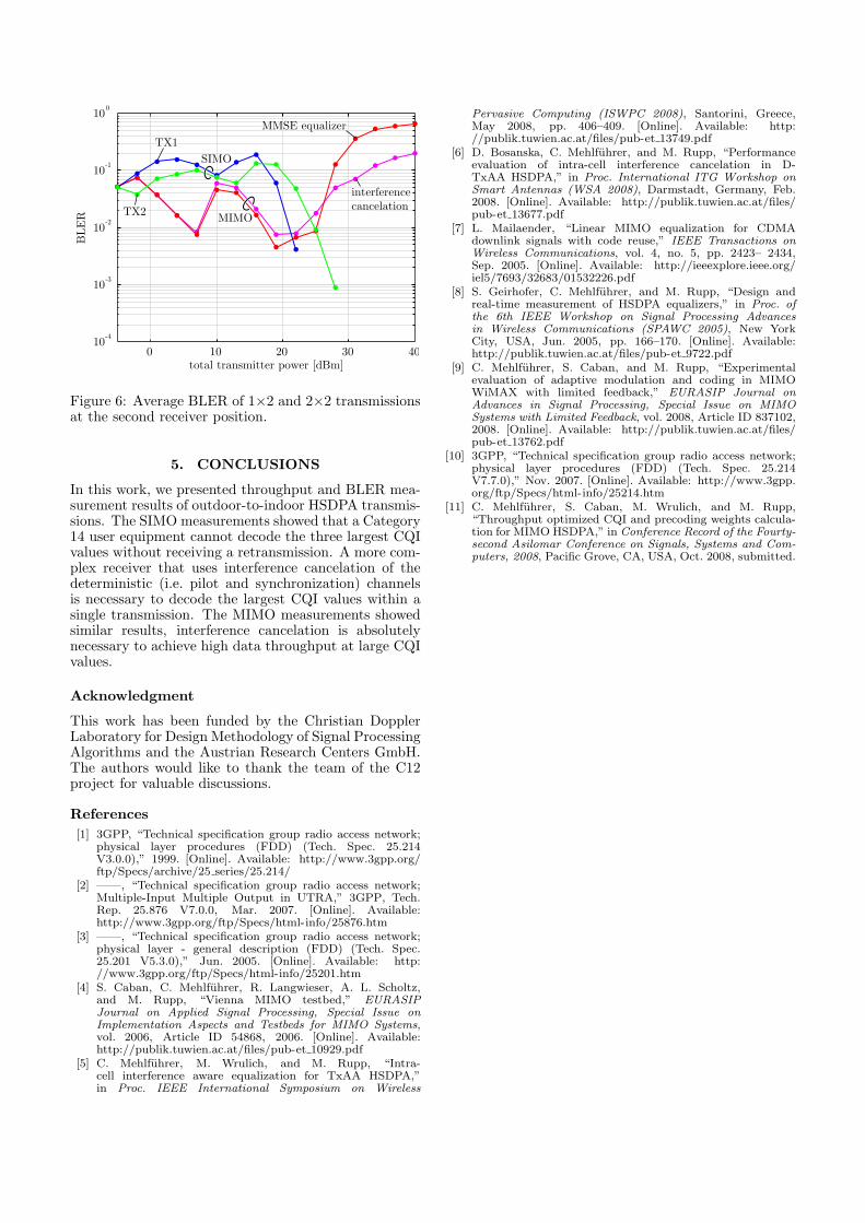
The BLER (Block Error Ratio) of the MIMO sys-tem is shown in Figures 4 and 6. Also here, a BLERbetween 2 and 10% is achieved over a large dynamicrange of about 30 dB. The straightforward MMSE equal-izer shows at large transmit power increased block errorratios causing the throughput loss noticed above.
0 10 20 30 40total transmitter power [dBm]
BLE
R MIMO
10-4
10-3
10-2
10-1
100
SIMO
TX2
interferencecancelation
MMSE equalizerTX1
Figure 6: Average BLER of 1×2 and 2×2 transmissionsat the second receiver position.
5. CONCLUSIONS
In this work, we presented throughput and BLER mea-surement results of outdoor-to-indoor HSDPA transmis-sions. The SIMO measurements showed that a Category14 user equipment cannot decode the three largest CQIvalues without receiving a retransmission. A more com-plex receiver that uses interference cancelation of thedeterministic (i.e. pilot and synchronization) channelsis necessary to decode the largest CQI values within asingle transmission. The MIMO measurements showedsimilar results, interference cancelation is absolutelynecessary to achieve high data throughput at large CQIvalues.
Acknowledgment
This work has been funded by the Christian DopplerLaboratory for Design Methodology of Signal ProcessingAlgorithms and the Austrian Research Centers GmbH.The authors would like to thank the team of the C12project for valuable discussions.
References[1] 3GPP, “Technical specification group radio access network;
physical layer procedures (FDD) (Tech. Spec. 25.214V3.0.0),” 1999. [Online]. Available: http://www.3gpp.org/ftp/Specs/archive/25 series/25.214/
[2] ——, “Technical specification group radio access network;Multiple-Input Multiple Output in UTRA,” 3GPP, Tech.Rep. 25.876 V7.0.0, Mar. 2007. [Online]. Available:http://www.3gpp.org/ftp/Specs/html-info/25876.htm
[3] ——, “Technical specification group radio access network;physical layer - general description (FDD) (Tech. Spec.25.201 V5.3.0),” Jun. 2005. [Online]. Available: http://www.3gpp.org/ftp/Specs/html-info/25201.htm
[4] S. Caban, C. Mehlfuhrer, R. Langwieser, A. L. Scholtz,and M. Rupp, “Vienna MIMO testbed,” EURASIPJournal on Applied Signal Processing, Special Issue onImplementation Aspects and Testbeds for MIMO Systems,vol. 2006, Article ID 54868, 2006. [Online]. Available:http://publik.tuwien.ac.at/files/pub-et 10929.pdf
[5] C. Mehlfuhrer, M. Wrulich, and M. Rupp, “Intra-cell interference aware equalization for TxAA HSDPA,”in Proc. IEEE International Symposium on Wireless
Pervasive Computing (ISWPC 2008), Santorini, Greece,May 2008, pp. 406–409. [Online]. Available: http://publik.tuwien.ac.at/files/pub-et 13749.pdf
[6] D. Bosanska, C. Mehlfuhrer, and M. Rupp, “Performanceevaluation of intra-cell interference cancelation in D-TxAA HSDPA,” in Proc. International ITG Workshop onSmart Antennas (WSA 2008), Darmstadt, Germany, Feb.2008. [Online]. Available: http://publik.tuwien.ac.at/files/pub-et 13677.pdf
[7] L. Mailaender, “Linear MIMO equalization for CDMAdownlink signals with code reuse,” IEEE Transactions onWireless Communications, vol. 4, no. 5, pp. 2423– 2434,Sep. 2005. [Online]. Available: http://ieeexplore.ieee.org/iel5/7693/32683/01532226.pdf
[8] S. Geirhofer, C. Mehlfuhrer, and M. Rupp, “Design andreal-time measurement of HSDPA equalizers,” in Proc. ofthe 6th IEEE Workshop on Signal Processing Advancesin Wireless Communications (SPAWC 2005), New YorkCity, USA, Jun. 2005, pp. 166–170. [Online]. Available:http://publik.tuwien.ac.at/files/pub-et 9722.pdf
[9] C. Mehlfuhrer, S. Caban, and M. Rupp, “Experimentalevaluation of adaptive modulation and coding in MIMOWiMAX with limited feedback,” EURASIP Journal onAdvances in Signal Processing, Special Issue on MIMOSystems with Limited Feedback, vol. 2008, Article ID 837102,2008. [Online]. Available: http://publik.tuwien.ac.at/files/pub-et 13762.pdf
[10] 3GPP, “Technical specification group radio access network;physical layer procedures (FDD) (Tech. Spec. 25.214V7.7.0),” Nov. 2007. [Online]. Available: http://www.3gpp.org/ftp/Specs/html-info/25214.htm
[11] C. Mehlfuhrer, S. Caban, M. Wrulich, and M. Rupp,“Throughput optimized CQI and precoding weights calcula-tion for MIMO HSDPA,” in Conference Record of the Fourty-second Asilomar Conference on Signals, Systems and Com-puters, 2008, Pacific Grove, CA, USA, Oct. 2008, submitted.