Embed Size (px)
Citation preview

Measurement of Blowby in a Turbocharger
JONNY TUOMINEN
Master of Science Thesis Stockholm, Sweden 2007
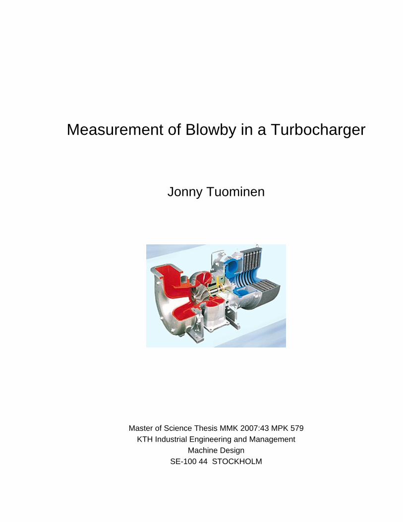
Measurement of Blowby in a Turbocharger
Jonny Tuominen
Master of Science Thesis MMK 2007:43 MPK 579 KTH Industrial Engineering and Management
Machine Design SE-100 44 STOCKHOLM

Master of Science Thesis MMK 2007:43 MPK 579
Measurement of Blowby in a Turbocharger
Jonny Tuominen
Approved
2007-04-03 Examiner
Priidu Pukk Supervisor
Priidu Pukk Commissioner
GM Powertrain Sweden AB Contact person
Eric Olofsson
Abstract The purpose with this Masters Thesis was to design a measurement rig for measurement of the blowby flow that originates from the turbocharger in a passenger car engine. A leakage of com-bustion gases and fresh air from the turbine and the compressor into the bearing housing of the turbocharger is the source of the blowby flow. Principally the measurement rig consists of two parts: a flowmeter for measurement of the blowby flow and a separation unit for separation of the blowby gases from the engine oil that is used for the lubrication of the bearings in the turbo-charger. The rig will be connected between the return oil pipe from the turbocharger and the en-gines crankcase and should only be used in engine testcells. First, an extensive study of different methods for measurement of gas flow and separation of gas and oil was carried out. Methods that best fulfill the set specifications of requirements are chosen to be used in the rig. From the results of the study a conclusion can be made that the best solu-tion is to use a flowmeter specifically made for engine blowby metering with another measure-ment pipe for more accurate measurements. A tank is used for the separation of oil and gas and it functions at the same time as a collecting vessel for the oil. A rack of baffle sheets inside the tank is used as the separation technique. The tank is also equipped with a pump and associated limit switches for controlling the oil level inside the tank. An oil heater is also applied to the tank for heating of the oil while kept in the tank.
Testing of the equipment was executed with an engine in testcells to verify the functionality of the equipment. A test cycle that extended over the engines whole load and speed range was used. Gained results show that the turbocharger blowby follows the same pattern as the total engine blowby. It increases with higher engine load rather than with higher engine speed. It is also pos-sible to confirm that the rig has an influence on the engines blowby system, but also that the size of it is not conclusive to the measurements. A conclusion that the turbocharger blowby should not be measured simultaneously with the engine blowby can be done from the test results.

Examensarbete MMK 2007:43 MPK 579
Mätning av “Blowby” i en turboladdare
Jonny Tuominen
Godkänt
2007-04-03
Examinator
Priidu Pukk
Handledare
Priidu Pukk Uppdragsgivare
GM Powertrain Sweden AB Kontaktperson
Eric Olofsson
Sammanfattning
Detta examensarbete omfattar konstruerandet av en mätningsrigg för mätning av det blowby-flöde som uppstår i en personbilsturbo. Blowby-flödet består av det läckage av förbränningsgaser och friskluft som sker genom turbin och kompressor in i lagerhuset på turboladdaren. Mätnings-riggen består huvudsakligen av två delar: en separationstank för separering av blowby-gaserna från den olja som används för smörjning av turbolagringen och en gasflödesmätare. Mätningsrig-gen kopplas in mellan turbons oljereturrör och motorn och den ska endast användas i motorprov-celler.
Arbetet innehåller en omfattande förstudie där olika metoder för mätning av gasflöde och separe-ring av olja och gas presenteras och diskuteras. Den mätningsmetod som väljs uppfyller bäst de ställda kraven. Resultatet från förstudien visar att den bästa mätningsmetoden är att använda en gasmätare konstruerad för blowby-mätning i motorer, men med ett annat mätrör. Separeringen av olja och gas sker inuti en tank som samtidigt fungerar som en uppsamlingsbehållare för oljan med hjälp av avrinningsplåtar. Tanken är utrustad med en pump med tillhörande styrdon samt en oljevärmare för uppvärmning av oljan i tanken.
Arbetet omfattade också provning av den framtagna utrustningen för att verifiera dess funktion. Provningen utfördes med en motor i motorprovcell med en testcykel som omfattade motorns hela last- och varvtalsregister. Provningens syfte var att undersöka om det går att mäta blowby genom turboladdaren med mätningsriggen samt att bestämma hur stor påverkan mätningsriggen har på motorn.
Resultatet visar att turboblowbyn följer samma mönster som den totala motorblowbyn. Den ökar mer med högre last än med högre motorvarvtal. Det kan också bekräftas att mätningsriggen har en inverkan på motorns blowby-system, men att den är så begränsad att den inte har en avgö-rande inverkan på mätningarna. Resultatet visar också att blowby-flödet genom turbon inte kan mätas samtidigt med motorblowbyn om den specificerade mätningsmetoden används.


TABLE OF CONTENTS
1 INTRODUCTION ...........................................................................................6
1.1 BACKGROUND ............................................................................................................................ 6 1.1.1 DESCRIPTION OF THE PROBLEM ........................................................................................ 7 1.1.2 BLOWBY IN THE TURBOCHARGER .................................................................................... 7 1.1.3 NEGATIVE EFFECTS OF THE BLOWBY .............................................................................. 9
1.2 OBJECT OF THE THESIS ........................................................................................................ 10
1.3 APPROACH ................................................................................................................................. 10
2 PROCEDURE..............................................................................................14
2.1 MEASUREMENT OF GAS FLOW........................................................................................... 14 2.1.1 TURBINE FLOWMETERS...................................................................................................... 14 2.1.2 VORTEX FLOWMETERS....................................................................................................... 16 2.1.3 HOT-WIRE ANEMOMETERS................................................................................................ 17 2.1.4 CORIOLIS FLOWMETER....................................................................................................... 18 2.1.5 FLOW MEASUREMENT WITH PITOT-TUBES................................................................... 18 2.1.6 FLOW MEASUREMENTS WITH VENTURIMETERS AND ORIFICE PLATES ............... 19
2.2 COMPARING THE MEASUREMENT METHODS............................................................... 22 2.2.1 COMPARING THE TECHNICAL PROPERTIES .................................................................. 22 2.2.2 COMPARING THE REQUIREMENTS................................................................................... 23
2.3 EVALUATION OF RESULT ..................................................................................................... 24
2.4 THE BLOWBY METER USED ................................................................................................. 24 2.4.1 BASIC WORKING PRINCIPLE.............................................................................................. 25
2.5 SEPARATION OF ENGINE OIL AND GAS ........................................................................... 27 2.5.1 SEPARATION MECHANISMS............................................................................................... 27 2.5.2 DEGASSING WITH GRAVITATION..................................................................................... 28 2.5.3 CENTRIFUGAL SEPARATION.............................................................................................. 28 2.5.4 CYCLONE SEPARATORS...................................................................................................... 30
2.6 CHOICE OF METHOD FOR SEPARATION ......................................................................... 30
3 MACHINERY...............................................................................................33
3.1 PRINCIPLE OF FUNCTION..................................................................................................... 33
3.2 THE SEPARATION TANK........................................................................................................ 34 3.2.1 RETURNING OIL TO ENGINE .............................................................................................. 35 3.2.2 HEATING OF THE OIL........................................................................................................... 37
4 TESTING .....................................................................................................39
4.1 MEASUREMENT OF TURBOCHARGER BLOWBY........................................................... 39 4.1.1 GAS RETURN TO CRANKCASE........................................................................................... 39 4.1.2 GAS RETURN TO OPEN ROOM ........................................................................................... 40
4.2 MEASUREMENT OF ENGINE BLOWBY.............................................................................. 41 4.2.1 ENGINE PREPARATIONS ..................................................................................................... 41
4.3 THE TEST OBJECTIVE ............................................................................................................ 41 4.3.1 ENGINE SPECIFICATIONS ................................................................................................... 41 4.3.2 TURBOCHARGER SPECIFICATONS ................................................................................... 42
4.4 THE TEST CYCLE ..................................................................................................................... 42 4.4.1 MEASURED VARIABLES...................................................................................................... 43
5 RESULTS....................................................................................................45
5.1 THE ACCOMPLISHED TESTS................................................................................................ 45
5.2 TURBOCHARGER BLOWBY .................................................................................................. 45
5.3 THE BLOWBY MEASURED WITH TWO METHODS ........................................................ 48
5.4 TURBO BLOWBY AND TOTAL ENGINE BLOWBY........................................................... 49 5.4.1 MEASURING WITH GAS RETURN TO ATMOSPHERIC PRESSURE .............................. 49 5.4.2 MEASURING WITH GAS RETURN TO CRANKCASE....................................................... 51
6 CONCLUSIONS ..........................................................................................53
7 RECOMMENDATIONS AND FURTHER WORK ........................................58
8 ACKNOWLEDGEMENTS ...........................................................................60
9 REFERENCES ............................................................................................62 APPENDIX 1: SPECIFICATION OF REQUIREMENTS APPENDIX 2: SPECIFICATION OF REQUIREMENTS FLOW MEASUREMENT APPENDIX 3: SPECIFICATION OF REQUIREMENTS SEPARATION UNIT APPENDIX 4: SPECIFICATION OF REQUIREMENTS PUMPING OF OIL
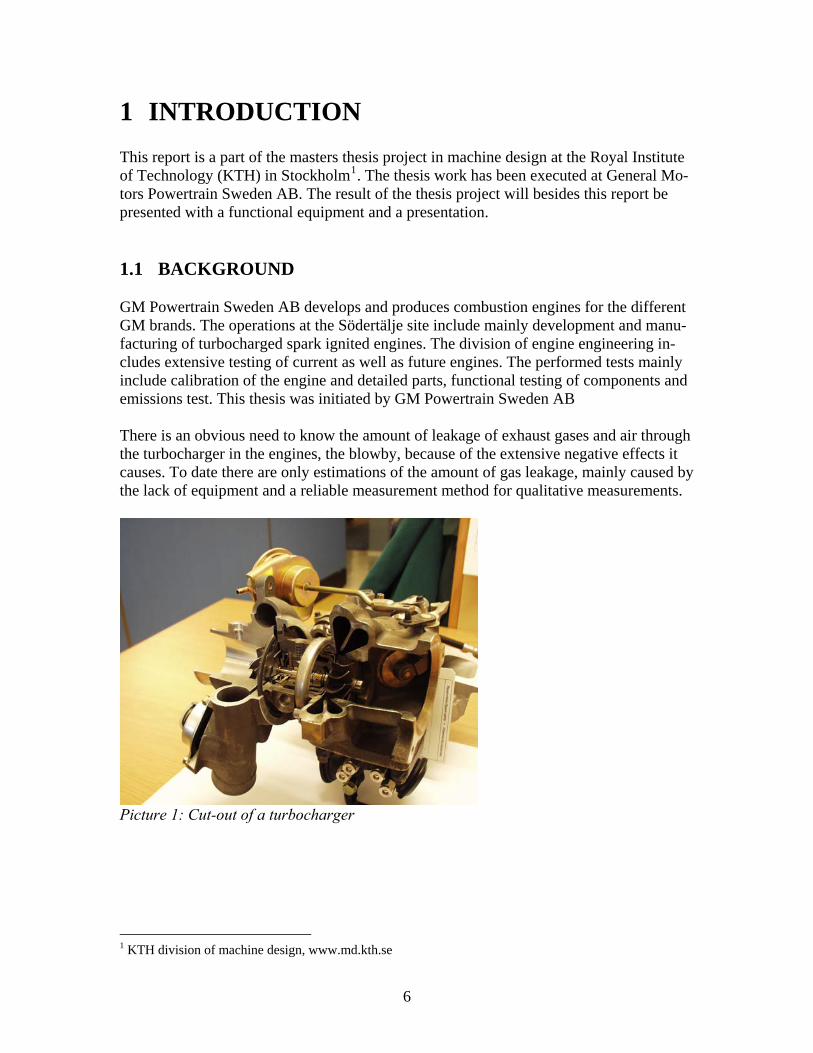
1 INTRODUCTION This report is a part of the masters thesis project in machine design at the Royal Institute of Technology (KTH) in Stockholm1. The thesis work has been executed at General Mo-tors Powertrain Sweden AB. The result of the thesis project will besides this report be presented with a functional equipment and a presentation. 1.1 BACKGROUND GM Powertrain Sweden AB develops and produces combustion engines for the different GM brands. The operations at the Södertälje site include mainly development and manu-facturing of turbocharged spark ignited engines. The division of engine engineering in-cludes extensive testing of current as well as future engines. The performed tests mainly include calibration of the engine and detailed parts, functional testing of components and emissions test. This thesis was initiated by GM Powertrain Sweden AB There is an obvious need to know the amount of leakage of exhaust gases and air through the turbocharger in the engines, the blowby, because of the extensive negative effects it causes. To date there are only estimations of the amount of gas leakage, mainly caused by the lack of equipment and a reliable measurement method for qualitative measurements.
Picture 1: Cut-out of a turbocharger
1 KTH division of machine design, www.md.kth.se
6

1.1.1 DESCRIPTION OF THE PROBLEM There are several advantages to gain in the possibility to measure the amount of blowby created in the turbocharger. This would give an increased understanding of how the dif-ferent parts of the system that generate blowby in the engine work, separately and as a system. There is a wish to be able to measure the specific flow separately through differ-ent parts of the engine, turbocharger and piston rings/cylinder walls. It is also desirable to establish the contribution given by the turbocharger to the total amount of blowby in the engine. The measurement results also give information about the dimensioning of the oil outlet from the turbocharger, the results can also be used for improvements in the design of the sealing elements in the bearing housing of the turbocharger. It would also be possible to establish how changes in the crankcase pressure affect the blowby flow through the tur-bocharger. There is also a wish for the ability to perform future measurements on the turbochargers provided by different suppliers in addition to benchmarking the differences in the quan-tity of gas leakage and differences in design of turbine, compressor and foremost bearing housing which to date varies between suppliers. The results of the measurements would facilitate and above all give information in the process of calibration and design of the turbocharger.
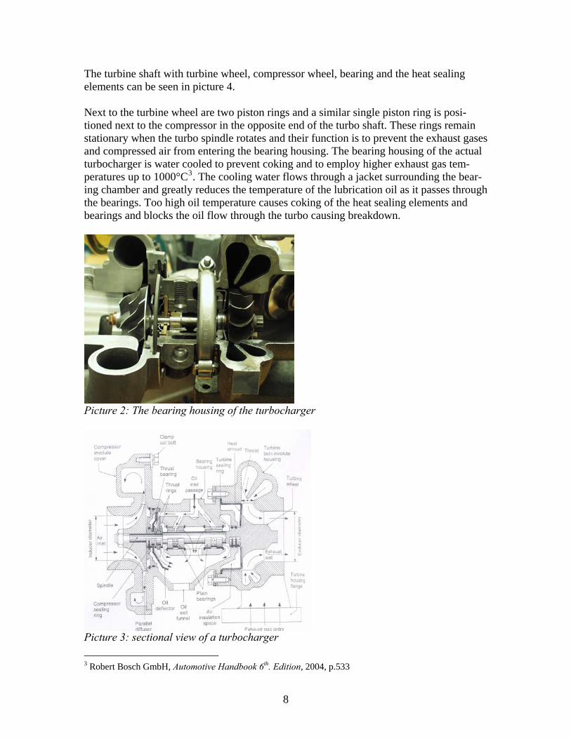
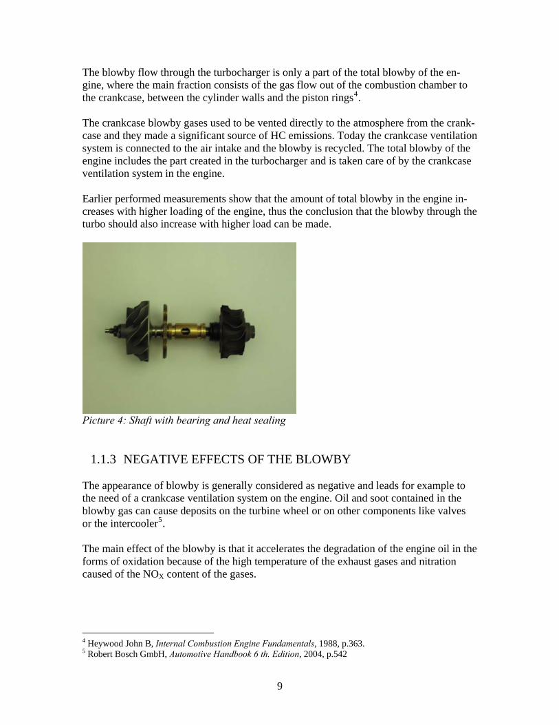
1.1.2 BLOWBY IN THE TURBOCHARGER The blowby gases are also known as crankcase ventilation gases and are produced as a result of the combustion. The gases flow from the combustion chamber through gaps mainly between the piston rings and the cylinder wall. The gas contains rest products from the incomplete combustion, soot and engine oil in the form of small droplets. The blowby flow in the turbocharger consists of the leakage of exhaust gases that pass the turbine wheel and fresh air that passes the compressor and entering the bearing housing via the sealing elements. A view of the bearing housing with the bearings and heat seal-ings can be seen in picture 2. The bearing-housing accommodates the bearings for the shaft that connects the turbine to the compressor. The radial bearings for the shaft are usually of the type rotating in double plain bushings and the bearings are lubricated by connecting the turbocharger to the engines oil circuit2. The oil outlet from the turbocharger is directly connected to the engines crankcase. Oil that passes through the bearings must be free to drain out quickly and without any serious restrictions. Gravity is the only force used to rid the bearing housing of oil. A sectional view of a turbocharger and its different parts can be seen in picture 3.
2 Robert Bosch GmbH, Automotive Handbook 6th. Edition, 2004, p.533.
7
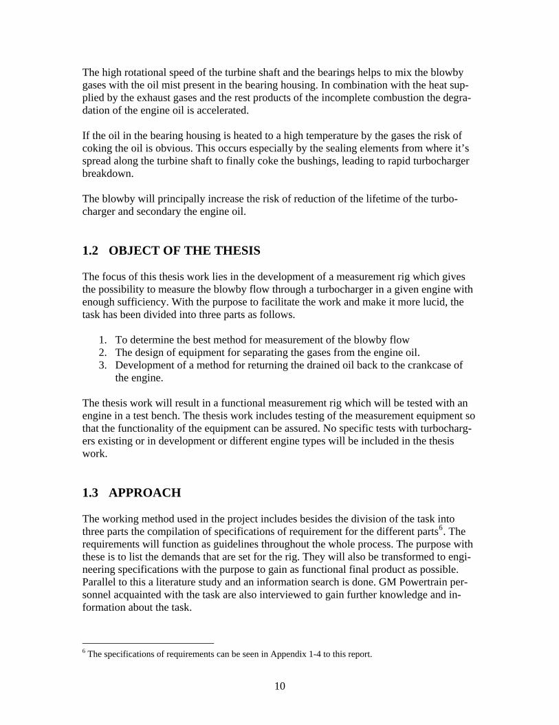
The turbine shaft with turbine wheel, compressor wheel, bearing and the heat sealing elements can be seen in picture 4. Next to the turbine wheel are two piston rings and a similar single piston ring is posi-tioned next to the compressor in the opposite end of the turbo shaft. These rings remain stationary when the turbo spindle rotates and their function is to prevent the exhaust gases and compressed air from entering the bearing housing. The bearing housing of the actual turbocharger is water cooled to prevent coking and to employ higher exhaust gas tem-peratures up to 1000°C3. The cooling water flows through a jacket surrounding the bear-ing chamber and greatly reduces the temperature of the lubrication oil as it passes through the bearings. Too high oil temperature causes coking of the heat sealing elements and bearings and blocks the oil flow through the turbo causing breakdown.
Picture 2: The bearing housing of the turbocharger
Picture 3: sectional view of a turbocharger 3 Robert Bosch GmbH, Automotive Handbook 6th. Edition, 2004, p.533
8
The blowby flow through the turbocharger is only a part of the total blowby of the en-gine, where the main fraction consists of the gas flow out of the combustion chamber to the crankcase, between the cylinder walls and the piston rings4. The crankcase blowby gases used to be vented directly to the atmosphere from the crank-case and they made a significant source of HC emissions. Today the crankcase ventilation system is connected to the air intake and the blowby is recycled. The total blowby of the engine includes the part created in the turbocharger and is taken care of by the crankcase ventilation system in the engine. Earlier performed measurements show that the amount of total blowby in the engine in-creases with higher loading of the engine, thus the conclusion that the blowby through the turbo should also increase with higher load can be made.
Picture 4: Shaft with bearing and heat sealing
1.1.3 NEGATIVE EFFECTS OF THE BLOWBY The appearance of blowby is generally considered as negative and leads for example to the need of a crankcase ventilation system on the engine. Oil and soot contained in the blowby gas can cause deposits on the turbine wheel or on other components like valves or the intercooler5. The main effect of the blowby is that it accelerates the degradation of the engine oil in the forms of oxidation because of the high temperature of the exhaust gases and nitration caused of the NOX content of the gases.
4 Heywood John B, Internal Combustion Engine Fundamentals, 1988, p.363. 5 Robert Bosch GmbH, Automotive Handbook 6 th. Edition, 2004, p.542
9
The high rotational speed of the turbine shaft and the bearings helps to mix the blowby gases with the oil mist present in the bearing housing. In combination with the heat sup-plied by the exhaust gases and the rest products of the incomplete combustion the degra-dation of the engine oil is accelerated. If the oil in the bearing housing is heated to a high temperature by the gases the risk of coking the oil is obvious. This occurs especially by the sealing elements from where it’s spread along the turbine shaft to finally coke the bushings, leading to rapid turbocharger breakdown. The blowby will principally increase the risk of reduction of the lifetime of the turbo-charger and secondary the engine oil. 1.2 OBJECT OF THE THESIS The focus of this thesis work lies in the development of a measurement rig which gives the possibility to measure the blowby flow through a turbocharger in a given engine with enough sufficiency. With the purpose to facilitate the work and make it more lucid, the task has been divided into three parts as follows.
1. To determine the best method for measurement of the blowby flow 2. The design of equipment for separating the gases from the engine oil. 3. Development of a method for returning the drained oil back to the crankcase of
the engine. The thesis work will result in a functional measurement rig which will be tested with an engine in a test bench. The thesis work includes testing of the measurement equipment so that the functionality of the equipment can be assured. No specific tests with turbocharg-ers existing or in development or different engine types will be included in the thesis work. 1.3 APPROACH The working method used in the project includes besides the division of the task into three parts the compilation of specifications of requirement for the different parts6. The requirements will function as guidelines throughout the whole process. The purpose with these is to list the demands that are set for the rig. They will also be transformed to engi-neering specifications with the purpose to gain as functional final product as possible. Parallel to this a literature study and an information search is done. GM Powertrain per-sonnel acquainted with the task are also interviewed to gain further knowledge and in-formation about the task.
6 The specifications of requirements can be seen in Appendix 1-4 to this report.
10

The design process includes the development of multiple solutions to the problem which
lead to several conceptual designs from which the one that best fulfills the set specifications will be further developed to a concept prototype and finally to a fi-nal product.
Because the fact that the blowby gases are mixed with the return oil leaving the turbo-charger, there is an obvious need to measure the blowby flow between the turbocharger and the engine before the oil and gas mixture is returned to the engines crankcase. It is also necessary to avoid mixing the blowby flow from the turbocharger with the blowby generated in the engine itself. The easiest way of measurement is to meter the gas flow after the turbo, before it’s returned to the engine. Another solution would be to make an outlet for the gas through the bearing housing. A problem would be that a hole through the cooling water jacket would cause leakage. It is also questionable if the gases could be exited from the bearing housing this way. To also be able to measure the gas flow is it necessary to drain the gas from the oil. The best way of doing this is simply to lead the oil from the turbocharger to a separate vessel where the draining of the gas can take place and from where the gas can be lead to a measuring device and the oil returned to the engine. This means that the rig will interfere with the oil return pipe between the turbocharger and the engine. The distance between the oil outlet on the turbocharger and the return oil inlet on the engine is similar to the length of the oil return pipe, which varies with engine type. This fact makes it difficult to place a separation device between the turbo and the engine.
Picture 5: Explanatory sketch of the measurement rig
11

Another solution is to separate the turbo from the engine by having a separate oil system to the turbocharger. The blowby flow through the turbocharger could be measured by measuring the total blowby of the engine with and without the turbo connected. A major drawback with this solution is that the turbo needs to be manually connected and discon-nected from the engine which makes it more difficult to perform testing of transients. To provide an acceptable and working oil supply to the turbocharger would be another prob-lem.
12

13
2 PROCEDURE 2.1 MEASUREMENT OF GAS FLOW Instruments used to measure a gas flow can be divided mainly into two classes. In the first class the total volumetric flow rate that flows in a given time is measured. The unit used for the volumetric flow rate is m3/s, for lower flow rates as in the actual case l/min is also commonly used. The other class measures the total mass flow that flows in a given time. The units used are kg/s or kg/hr. Mass flowmeters are particularly more useful when dealing with gases, as the volumetric flow varies more with temperature and pressure than with liquid and solids. The mass flowmeters can be divided into two subclasses. Those who use direct velocity measurement of the gas flow and those using pressure-differential measurement over a contraction in the flow field7. There is a large amount of manufacturers offering flowmeters of all types in the market, why a reasonable solution in the choice of meter is to use an existing meter. These meters also have the possibility to measure both mass flow and volumetric flow and have serial interface so that they can be connected to a PC. The blowby measurements at GM Power-train Sweden AB are done in volumetric flow with the unit l/min. in consideration to make the measurements comparable with earlier and future measurements it is in this case preferable to measure volumetric flow. Nevertheless is it still important to determine the measuring technique that preferably should be used. A common feature in all the meters is that they disturb the flow pattern by placing a probe or a device in the flow field. The meters are therefore of the insertion type and can be installed directly in the flow. These instruments have been developed to measure di-rectly the rate and direction of the gas flow.
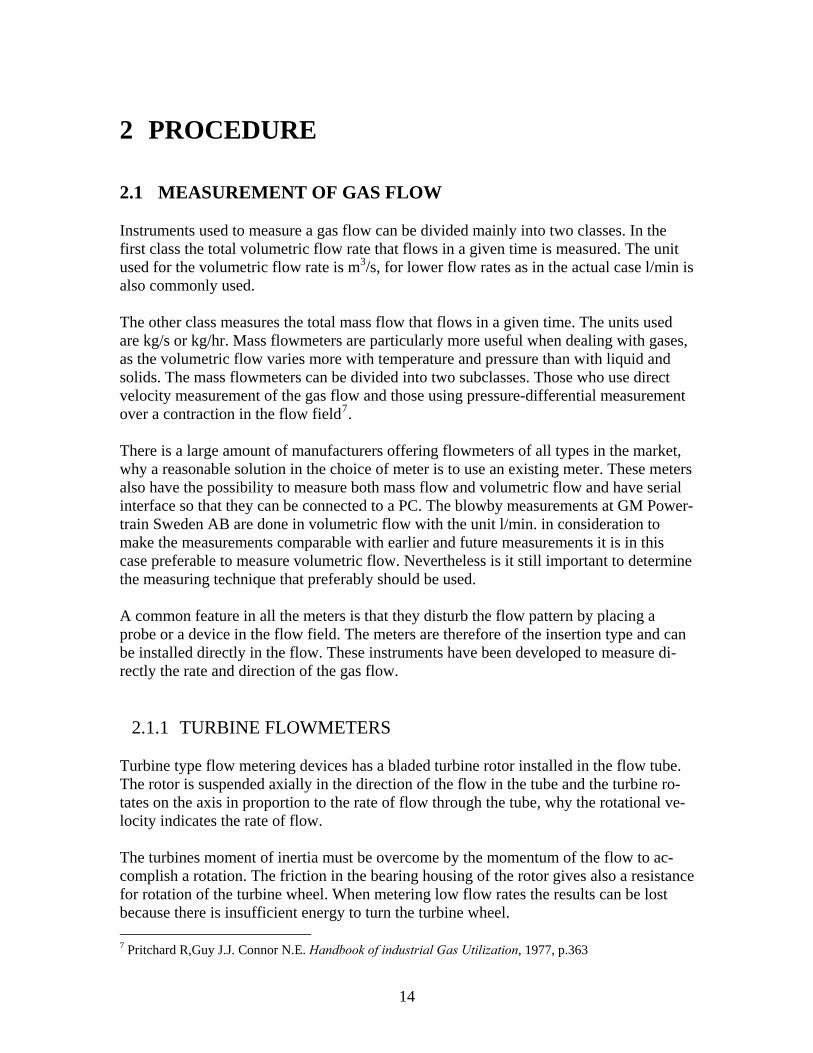
2.1.1 TURBINE FLOWMETERS Turbine type flow metering devices has a bladed turbine rotor installed in the flow tube. The rotor is suspended axially in the direction of the flow in the tube and the turbine ro-tates on the axis in proportion to the rate of flow through the tube, why the rotational ve-locity indicates the rate of flow. The turbines moment of inertia must be overcome by the momentum of the flow to ac-complish a rotation. The friction in the bearing housing of the rotor gives also a resistance for rotation of the turbine wheel. When metering low flow rates the results can be lost because there is insufficient energy to turn the turbine wheel. 7 Pritchard R,Guy J.J. Connor N.E. Handbook of industrial Gas Utilization, 1977, p.363
14
The energy needed to accomplish rotation is emitted by the gas which causes a pressure drop in it. If the pressure drop is large enough an accurate measurement of the gas flow can not be contrived. The turbine wheel used for gas metering should be designed to have low weight to mini-mize the rotational resistance. The turbine wheel is commonly made of cast steel, alumi-num or in a variation of plastic materials8.
Picture 6: Sectional view of a turbine flow meter The rotational velocity of the rotor is usually detected with a sensor that creates a mag-netic field in the flow tube, so that every passage of a rotor blade is detected. This means that every output signal of the sensor has been generated when a certain volumetric flow has passed the meter. The quantity of output signals per unit of time is proportional to the rate of flow. An advantage with the turbine flowmeters is that they are suitable for measurement of high pressure and temperature gases. They are also good in measurement of high volu-metric flows and have a wide operational temperature range. There are unless this several influencing factors in the use of these meters since they consist of moving parts.
• The temperature, pressure and viscosity of the fluid being measured. • Bearing wear and friction. • The conditional and dimensional changes of the blades. • Pressure drop through the flowmeter.
8 Pritchard R,Guy J.J. Connor N.E. Handbook of industrial Gas Utilization, 1977, p.369
15
2.1.2 VORTEX FLOWMETERS
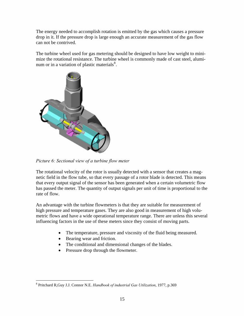
Flowmeters using Vortex Shedding use an object usually called shedding bar in the path of the fluid. When the flow passes this obstacle in its path vortices are created on both sides of the object. The vortices of one side rotate clockwise while those of the other side rotate counterclockwise. These vortices are generated alternating from one side to the other of the shedder bar9. Close to the shedder bar the wave length between the vortices is always constant and measurable, therefore is the volume encompassed by each vortex constant. The frequency of the vortices is proportional to the Strouhal number, the flow velocity and the diameter of the shedder bar10.
duSrf ⋅
∝ [1]
f = frequency [Hz] Sr = Strouhal number [dimensionsless] u = Mean pipe flow velocity [m/s] d = Body diameter [m] Piezoelectric elements are usually used to sense the frequency of the vortices. When the flow is increased, the number of vortices increases creating a linear relation. The vortex flowmeters are highly sensitive for changes in the rate of flow giving good accuracy characteristics. They also operate over a wide range of flows, pressure and temperature. They also don’t include any moving parts and has a low resistance to flow. Disadvan-tages are that at low flow rates, no pulses are generated and the flowmeter can read zero. Vibrations nearby the meter can also cause errors in accuracy.
Picture 7: Inline Vortex flowmeter
9 Alvarez H, Energiteknik, 1990, p.51 10 http://www.spiraxsarco.com/resources/steam-engineering-tutorials/flowmetering/types-of-steam-flowmeter.asp#head76
16

2.1.3 HOT-WIRE ANEMOMETERS Hot-wire instruments is a commonly known method for flow measurement of gas. They involve an electrically heated thin metal wire placed in the path of the gas stream. The wire is usually made of platinum or platinum-coated wolfram. The wire is cooled by the passing gas stream why a higher velocity of flow results in a more efficient cooling of the wire. The loss of heat from the wire to the surrounding gas indicates the amount of elec-tric energy supplied to the wire. The temperature of the wire can then be determined by measurement of the resistance which will increase with higher temperature11. An advantage with this technique is that it uses very small measuring probes. A com-monly used wire diameter is 5µm with the wire length of 1 mm and more. Hot-wire in-struments can be used for measuring laminar, transitional and turbulent flow.
Picture 8: The working principle of the Hot-wire anemometer There are two functional principles for hot-wire anemometers. The first is when the tem-perature of the wire is detected by measuring the resistance of the wire which varies with the temperature. These are called constant current anemometers (CCA). The main draw-back with this method is that when the velocity of the flow changes rapidly, for example in the case of turbulent flow, the reaction time for the wires change in temperature causes an error in the measurements. It should also be noted that changes or variations in the temperature of the gas also affects the cooling of the wire. A calculated correction for this can be made by measuring the gas temperature at the same time. The second method for hot-wire measurement is to regulate the power supplied to the wire so that the resistance of the wire is kept constant. This results in a constant wire temperature and the power needed to accomplish this is proportional to the flow rate. This method is suitable for low velocity gas flows.
11 Pritchard R,Guy J.J. Connor N.E. Handbook of industrial Gas Utilization, 1977, p.374
17
A drawback with this method is that a certain minimum flow is acquired to get a reading on the meter. The gas flow also needs to be completely free from particles or liquid mist to avoid contamination of the wires, which leads to impaired accuracy and general mal-function.
2.1.4 CORIOLIS FLOWMETER The flowmeter can be used to measure the mass flow rate of a gas or a liquid. The operat-ing principle of the flowmeter uses the Coriolis effect. There are two basic configurations of the Coriolis flowmeter, the curved tube flow meter introducing two parallel tubes and the straight tube flowmeter with one single tube. In the curved tube flow meter the gas flow is led through two parallel elastic plastic tubes and the flowmeters operating principle essentially involves rotation, though not through a full circle. It works by inducing a vibration of the tubes that the flow passes through so that an oscillation of the tubes occurs. Mass flow thru the tubes generates Coriolis forces which appear when a particle with mass moves radially in a rotating system. The Coriolis forces deform the tubes and this deformation can be detected with sensors. The phase displacement between the frequencies of the tubes is proportional to the mass flow rate. The forces also have opposite effect on the inlet and outlet sides of the tube which is used in the straight tube flowmeter . The vibration on the inlet side is dampened because flow with no kinetic energy in the sideway direction is entering the tube. The vibration of the outlet side is stronger because flow with a lot of kinetic energy is moving from the inlet part to the outlet. In the straight tube flowmeter sensors are detecting the deformation of the tube by the inlet and the outlet part. The flowmeters using the Coriolis principle are known to be extremely accurate and fast in response to changing flow rates. The main drawback with them is their sensitiveness against contamination of the measured gas with liquid or solid particles.
2.1.5 FLOW MEASUREMENT WITH PITOT-TUBES Using Pitot-tubes is a generally known method for flow measurement. They are very use-ful devices for making temporary measurements of flow. The tube has a cylindrical shape and is placed with its open end facing into the stream. The tube has a hemispherical tip with an impact hole which should be cylindrical and placed central with respect to the hemisphere. The principle of operation is that the impinging gas flow will be brought to rest inside the tube and the kinetic energy is converted to pressure energy. The result of this is that the pressure inside the tube is higher than the ambient pressure of the flow sur-rounding the tube12.
12 Pritchard R,Guy J.J. Connor N.E. Handbook of industrial Gas Utilization, 1977, p.380
18
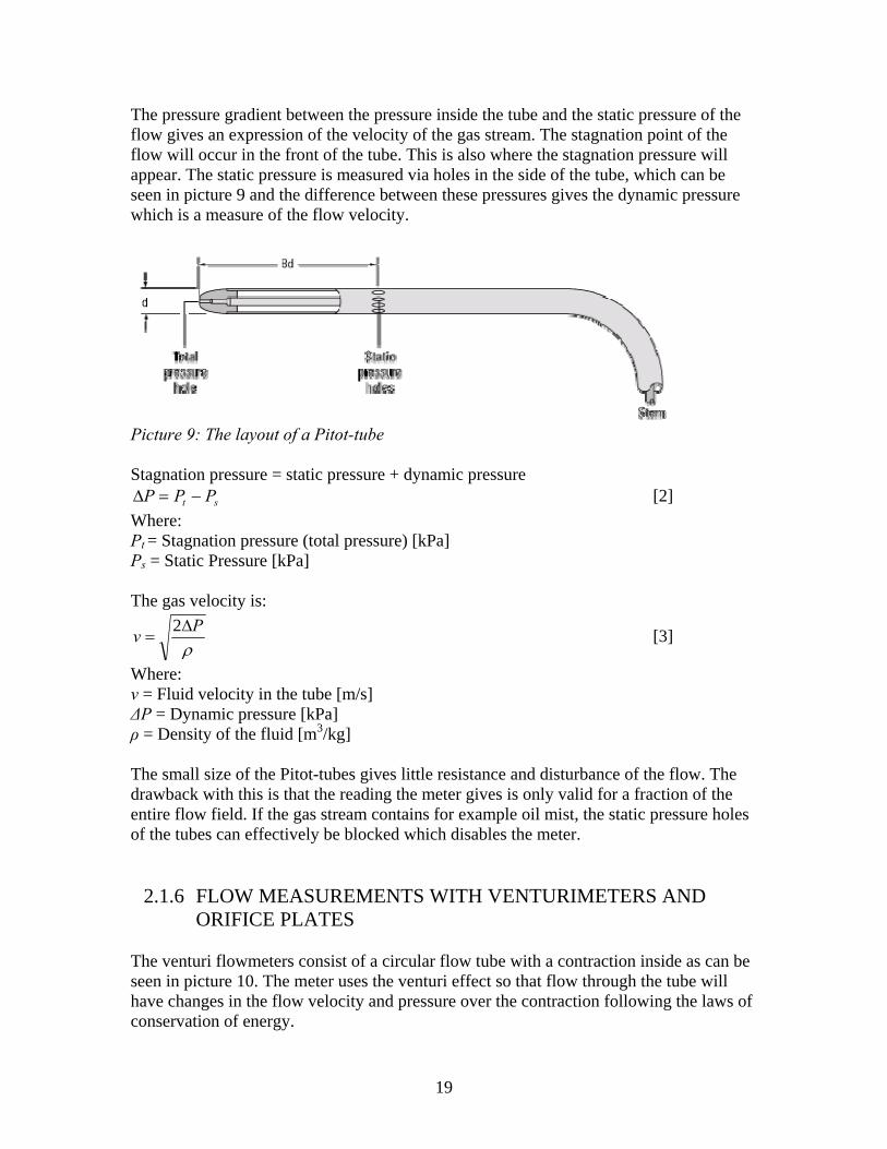
The pressure gradient between the pressure inside the tube and the static pressure of the flow gives an expression of the velocity of the gas stream. The stagnation point of the flow will occur in the front of the tube. This is also where the stagnation pressure will appear. The static pressure is measured via holes in the side of the tube, which can be seen in picture 9 and the difference between these pressures gives the dynamic pressure which is a measure of the flow velocity.
Picture 9: The layout of a Pitot-tube Stagnation pressure = static pressure + dynamic pressure
st PPP −=Δ [2] Where: Pt = Stagnation pressure (total pressure) [kPa] Ps = Static Pressure [kPa] The gas velocity is:
ρPv Δ
=2 [3]
Where: v = Fluid velocity in the tube [m/s] ΔP = Dynamic pressure [kPa] ρ = Density of the fluid [m3/kg] The small size of the Pitot-tubes gives little resistance and disturbance of the flow. The drawback with this is that the reading the meter gives is only valid for a fraction of the entire flow field. If the gas stream contains for example oil mist, the static pressure holes of the tubes can effectively be blocked which disables the meter.
2.1.6 FLOW MEASUREMENTS WITH VENTURIMETERS AND ORIFICE PLATES
The venturi flowmeters consist of a circular flow tube with a contraction inside as can be seen in picture 10. The meter uses the venturi effect so that flow through the tube will have changes in the flow velocity and pressure over the contraction following the laws of conservation of energy.
19
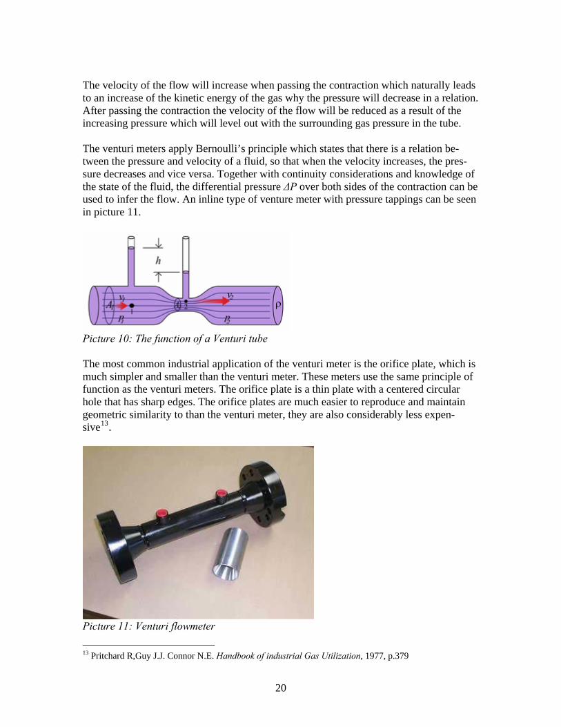
The velocity of the flow will increase when passing the contraction which naturally leads to an increase of the kinetic energy of the gas why the pressure will decrease in a relation. After passing the contraction the velocity of the flow will be reduced as a result of the increasing pressure which will level out with the surrounding gas pressure in the tube. The venturi meters apply Bernoulli’s principle which states that there is a relation be-tween the pressure and velocity of a fluid, so that when the velocity increases, the pres-sure decreases and vice versa. Together with continuity considerations and knowledge of the state of the fluid, the differential pressure ΔP over both sides of the contraction can be used to infer the flow. An inline type of venture meter with pressure tappings can be seen in picture 11.
Picture 10: The function of a Venturi tube The most common industrial application of the venturi meter is the orifice plate, which is much simpler and smaller than the venturi meter. These meters use the same principle of function as the venturi meters. The orifice plate is a thin plate with a centered circular hole that has sharp edges. The orifice plates are much easier to reproduce and maintain geometric similarity to than the venturi meter, they are also considerably less expen-sive13.
Picture 11: Venturi flowmeter
13 Pritchard R,Guy J.J. Connor N.E. Handbook of industrial Gas Utilization, 1977, p.379
20
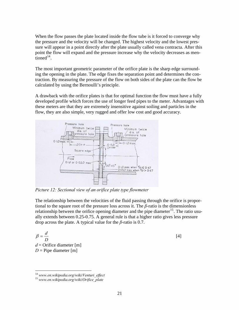
When the flow passes the plate located inside the flow tube is it forced to converge why the pressure and the velocity will be changed. The highest velocity and the lowest pres-sure will appear in a point directly after the plate usually called vena contracta. After this point the flow will expand and the pressure increase why the velocity decreases as men-tioned14. The most important geometric parameter of the orifice plate is the sharp edge surround-ing the opening in the plate. The edge fixes the separation point and determines the con-traction. By measuring the pressure of the flow on both sides of the plate can the flow be calculated by using the Bernoulli’s principle. A drawback with the orifice plates is that for optimal function the flow must have a fully developed profile which forces the use of longer feed pipes to the meter. Advantages with these meters are that they are extremely insensitive against soiling and particles in the flow, they are also simple, very rugged and offer low cost and good accuracy.
Picture 12: Sectional view of an orifice plate type flowmeter The relationship between the velocities of the fluid passing through the orifice is propor-tional to the square root of the pressure loss across it. The β-ratio is the dimensionless relationship between the orifice opening diameter and the pipe diameter15. The ratio usu-ally extends between 0.25-0.75. A general rule is that a higher ratio gives less pressure drop across the plate. A typical value for the β-ratio is 0.7.
Dd
=β [4]
d = Orifice diameter [m] D = Pipe diameter [m]
14 www.en.wikipedia.org/wiki/Venturi_effect 15 www.en.wikipedia.org/wiki/Orifice_plate
21
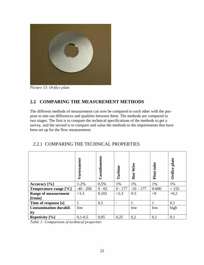
Picture 13: Orifice plate 2.2 COMPARING THE MEASUREMENT METHODS The different methods of measurement can now be compared to each other with the pur-pose to aim out differences and qualities between them. The methods are compared in two stages. The first is to compare the technical specifications of the methods to get a survey, and the second is to compare and value the methods to the requirements that have been set up for the flow measurement.
2.2.1 COMPARING THE TECHNICAL PROPERTIES
Vor
texm
eter
Cor
iolis
met
er
Tur
bine
Hot
-Wir
e
Pito
t-tu
be
Ori
fice
plat
e
Accuracy [%] 1-2% 0,5% 1% 1% 1% 1% Temperature range [°C] -40 - 200 0 - 65 0 - 177 -10 – 177 0-600 < 155 Range of measurement [l/min]
>3.3 0,102 >2,3 0-5 >0 >0,2
Time of response [s] 1 0,5 - 1 1 0,1 Contamination durabil-ity
low low low high
Repetivity [%] 0,1-0,5 0,05 0,25 0,2 0,1 0,1 Table 1: Comparison of technical properties
22

The accuracy is given as a percentage of the total flow. The most available flowmeters upper range of measurement is very high compared to the actual need, why the minimum range of the meters is compared. The repetivity of the methods are a value of accuracy, in this case given as a percentage of the total flow. The values in the table come from a selection of flowmeter manufacturers and are valid for present existing products available on the market.
2.2.2 COMPARING THE REQUIREMENTS The matrix lists the requirements that has been set up for the flow measurement and compares the different solutions for every requirement against a reference solution. In this case the Hot-Wire measurement method is chosen as the reference solution, because it is the most common technique for gas flow measurement, there is also a large knowl-edge of this method. The matrix is only a guideline that shows and compares advantages and disadvantages of the different measuring methods. A drawback with this method is that it doesn’t give any information or numerical value of how much better or worse one solution is compared to another. This is also very hard to estimate. The matrix doesn’t use any weighting of the different criteria because setting a value for each criterion could dramatically change the result. It is also difficult to value the requirements to each other in the mean of importance.
Vor
texm
eter
Cor
oilis
met
er
Tur
bine
Hot
-Wir
e
Pito
t-tu
be
Ori
fice
plat
es
Accuracy - + 0 0 0 Range of meas. - + - 0 + Easy to use 0 0 0 0 0 Calibration 0 0 0 0 0 Temperature sens. + - - + 0
Possibility to change probe
- - - 0 0
Sensitivity against contamination
+ - + + +
Fysical size 0 0 - - - Stability* + - + 0 + Total + 0 -2 -2 +1 +2 Table 2: Comparison matrix
23
The criterions used in the matrix are picked from the set specifications of requirement,
which can be seen in appendix 1 to 4 of this report. Each method is compared to the reference solution in this case the Hot-Wire method.
If the method fulfills the criterion better than the reference it’s given a +, if it’s worse it’s
given a -. If the method is equal or not comparable to the reference it’s given a 0. Each column is then added so that the final result for the method is obtained.
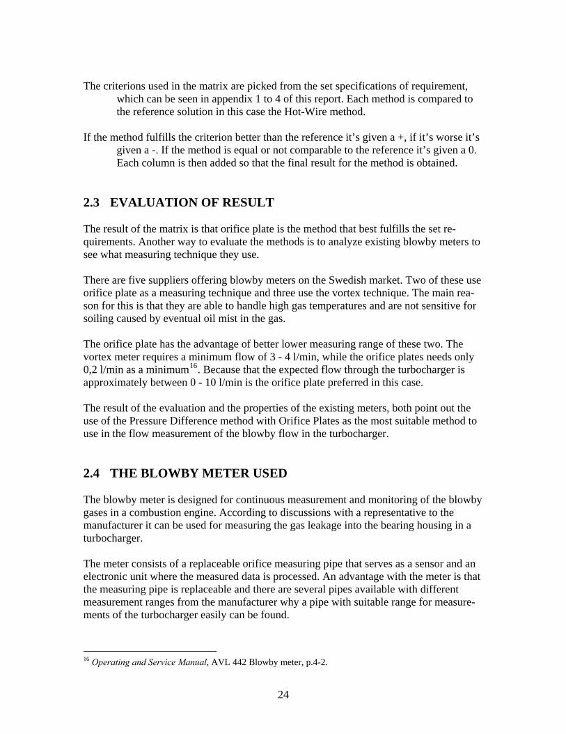
2.3 EVALUATION OF RESULT The result of the matrix is that orifice plate is the method that best fulfills the set re-quirements. Another way to evaluate the methods is to analyze existing blowby meters to see what measuring technique they use. There are five suppliers offering blowby meters on the Swedish market. Two of these use orifice plate as a measuring technique and three use the vortex technique. The main rea-son for this is that they are able to handle high gas temperatures and are not sensitive for soiling caused by eventual oil mist in the gas. The orifice plate has the advantage of better lower measuring range of these two. The vortex meter requires a minimum flow of 3 - 4 l/min, while the orifice plates needs only 0,2 l/min as a minimum16. Because that the expected flow through the turbocharger is approximately between 0 - 10 l/min is the orifice plate preferred in this case. The result of the evaluation and the properties of the existing meters, both point out the use of the Pressure Difference method with Orifice Plates as the most suitable method to use in the flow measurement of the blowby flow in the turbocharger. 2.4 THE BLOWBY METER USED The blowby meter is designed for continuous measurement and monitoring of the blowby gases in a combustion engine. According to discussions with a representative to the manufacturer it can be used for measuring the gas leakage into the bearing housing in a turbocharger. The meter consists of a replaceable orifice measuring pipe that serves as a sensor and an electronic unit where the measured data is processed. An advantage with the meter is that the measuring pipe is replaceable and there are several pipes available with different measurement ranges from the manufacturer why a pipe with suitable range for measure-ments of the turbocharger easily can be found.
16 Operating and Service Manual, AVL 442 Blowby meter, p.4-2.
24
The measurement pipes used has the range of 1.5 - 75 l/min. and 3 - 150 l/min. Picture 14 shows a measurement pipe withholding the Orifice plate. The test cells at the GM Powertrain site are also equipped with similar type of meters why there is knowledge of the function of these in house. The manufacturer has also rep-resentation in the nearby area why service or training is facilitated if needed. Drawbacks with the equipment are that flow rates near the lower end of the measuring range or noise in the pressure sensors can cause fluctuation in the measured results. This can be pre-vented by carrying out the measurements over a period of time, recommended at least 30 seconds, and taking the mean values of the results. Heavily soiled blowby gas can also cause contamination that negatively affects the measurement results when measuring over a longer period of time17.
Picture 14: The measurement pipe
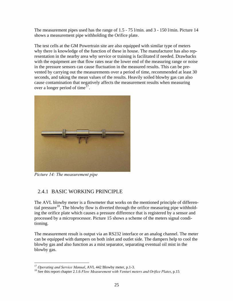
2.4.1 BASIC WORKING PRINCIPLE The AVL blowby meter is a flowmeter that works on the mentioned principle of differen-tial pressure18. The blowby flow is diverted through the orifice measuring pipe withhold-ing the orifice plate which causes a pressure difference that is registered by a sensor and processed by a microprocessor. Picture 15 shows a scheme of the meters signal condi-tioning. The measurement result is output via an RS232 interface or an analog channel. The meter can be equipped with dampers on both inlet and outlet side. The dampers help to cool the blowby gas and also function as a mist separator, separating eventual oil mist in the blowby gas.
17 Operating and Service Manual, AVL 442 Blowby meter, p.1-3. 18 See this report chapter 2.1.6 Flow Measurement with Venturi meters and Orifice Plates, p.15
25
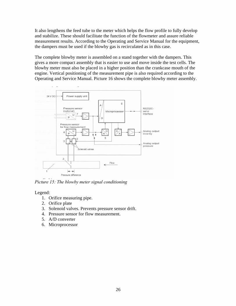
It also lengthens the feed tube to the meter which helps the flow profile to fully develop and stabilize. These should facilitate the function of the flowmeter and assure reliable measurement results. According to the Operating and Service Manual for the equipment, the dampers must be used if the blowby gas is recirculated as in this case. The complete blowby meter is assembled on a stand together with the dampers. This gives a more compact assembly that is easier to use and move inside the test cells. The blowby meter must also be placed in a higher position than the crankcase mouth of the engine. Vertical positioning of the measurement pipe is also required according to the Operating and Service Manual. Picture 16 shows the complete blowby meter assembly.
Picture 15: The blowby meter signal conditioning Legend:
1. Orifice measuring pipe. 2. Orifice plate 3. Solenoid valves. Prevents pressure sensor drift. 4. Pressure sensor for flow measurement. 5. A/D converter 6. Microprocessor
26
Picture 16: The AVL-442 blowby meter assembled with dampers 2.5 SEPARATION OF ENGINE OIL AND GAS
2.5.1 SEPARATION MECHANISMS There are several different mechanisms used for separating liquid and gas. These can be used solely or in combination. The most commonly used and simplest mechanism is the use of gravitational force, also known as settling. This occurs when the drag created by the flowing gas is less than the weight of the liquid droplets. This mechanism can be used in the actual case by letting the oil and gas mixture run along surfaces so that the gas is drained from the oil. The main drawback of this mechanism is that it requires time. A faster mechanism that can be used is the centrifugal force, when the fact that the oil and gas molecules has different mass is used, since the oil molecules are heavier will they separate from the gas under influence of the centrifugal force. The centrifugal force can exceed the gravitational force with a factor up to 10000. This is also the main cause why this mechanism is faster. Another advantage is that a high grade separation is possible under a short period of time. Another separation mechanism is a method where the flowing medium collides with an obstacle placed in the path of the flowing stream. For example can the stream be led into a non-straight channel. When the oil-droplets tend to go in straighter paths and collide with the obstacles will the gas stream follow the path. When the liquid particles impact with the obstacle they will loose momentum and therefore coalesce.
27
The accuracy of the separation is determined by the oil-droplets size in the stream. Larger droplets have more momentum and will follow a straighter path. The velocity of the stream has also an effect on the accuracy because of the increase of momentum with higher velocity. The difference in density between the gas and the liquid is also signifi-cant19. Brownian motion is also a mechanism of separation which occurs in submicron particles. Brownian motion is the random motion of particles suspended in gas or liquid. The cause of this is explained by the momentary inequality in the number and velocity of the sur-rounding molecules which hit the particle randomly from various directions. This ex-tremely tiny motion is enough to separate liquid and gas by throwing droplets of the oil out of the stream of the gas so that they can be cached by obstacles placed in the stream. The efficiency of the separation can be increased with higher temperature of the gas and oil mixture and closer packaging of the material the obstacles are made of20.
2.5.2 DEGASSING WITH GRAVITATION The oil and gas mixture can be separated by letting the oil flow along surfaces, for exam-ple steel sheets, commonly known as baffle sheets. This method uses the gravitational force which makes the oil flow downwards inside a container with the sheets inside. High collecting efficiency can be accomplished using this method. The main drawback of this method is that it requires time. If the system is encroaching in the oil circulation system of the engine it will be necessary to increase the total amount of oil in the system. Advan-tages with this solution are the freedom it gives in designing the oil separator, the wide industrial usage and the low cost that it offers. The developed concepts that use the gravitational force use the general idea that the gravitational force impels the gas and oil mixture through the container. The concepts generate a closed container with a top placed oil inlet, the oil flows along sheet metal plates, perforated plates or dense metal net placed inside the container. The separation will occur under the time the mixture is detained by the plates. The gas drained oil is col-lected in the bottom of the container from which it can be returned to the engine. The to-tal oil volume is easy to regulate with pumping from the container.
2.5.3 CENTRIFUGAL SEPARATION Centrifugal devices can be used for the separation of oil and gas, because of the differ-ence in density between them. Using centrifuges for separation makes it possible to ac-complish a fast high-grade separation compared to other techniques. The rapidness of this technique has it origin in the use of centrifugal force which in some devices can be ap-proximately 10 000 times the gravitation force.
19 http://www.amistco.com/BULLS_PDF/MeshVaneSM.pdf 20 http://www.amistco.com/BULLS_PDF/MeshVaneSM.pdf
28

The centrifugal force appears in this case when a vessel containing the medium to be separated is rotated. This creates a centrifugal acceleration which depends of the angular velocity and the distance to the axis of rotation.
22 ωra = [5] a = centrifugal acceleration [m/s2] r = Rotational radius [m] ω = Angular velocity [s-1] The rotation axis of the centrifugal separator has several conical discs with holes stacked on top of each other in a manner so that the holes form a passage thru the discs. The oil and gas mixture is led into the separation bowl which is rotated. With the influence of the centrifugal force a separation is achieved when the part of the mixture with higher den-sity, in this case oil, is forced against the outer edges of the discs and the substance with lower density stays closer to the rotational axis. The heavier material will be transported downwards along the inside wall of the housing, from where it runs to a sump and an oil outlet at the bottom of the device. The gas is transported via the passages in the discs thru an outlet in the top of the separator21. Centrifugal separators can be used for separating solids from liquids as well as gas and liquids. The separator can be driven by an electric motor or with hydraulic power. The drawback with this method is the high cost and the complexity with several parts, for ex-ample motor, drive and gear.
Picture 17: Centrifugal separator
21 Project report: Centrifugalseparering, Lunds Tekniska Högskola, 2006, p.5-6
29
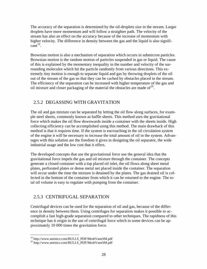
2.5.4 CYCLONE SEPARATORS
Cyclone separators consist of a cylindrical container with a conical shape at the bottom. The inlet which can have a rectangular or a circular shape is placed tangentially on the side of the container. The gas outlet has the shape of a pipe placed thru the top of the cyl-inder and with the other end inside the cylinder below the inlet. The oil outlet consists of an opening at the end of the conical part of the cylinder22. Separation occurs when the flow inside the cylinder is set in a swirl which forces the flow to tangentially move downwards along the outer walls of the container. The gas will move inwards and upwards in the conical part of the separator, while the oil which is the heavier substance of the mixture foremost because of the gravitation will continue downwards and finally leave the cyclone via the outlet at the bottom. The separation effi-ciency is dependent of the velocity of the flow into the cyclone and of the inside diameter of the cylinder. Cyclone separators are primarily used for separating solids from a gas stream but they can also be used for gas separation from liquids.
Picture 18: The function of a cyclone separator
2.6 CHOICE OF METHOD FOR SEPARATION Using a centrifugal device for separation in this case is the most expensive solution be-cause of the amount of equipment needed. It will also make the separation equipment more complex and require most space. A brief search on available centrifugal separators also show that they are more optimized for separating liquids with different density rather than gas and liquid.
22 Hoffman A.C. Stein L.E. Gas Cyclones and Swirl Tubes, p.37-38
30
Using cyclones is a solution that gives a lower cost, but in this specific case it is con-nected with an uncertainty because the oil has a very high grade of mixing with the blowby gases when leaving the turbocharger and contains foam. Because of these reasons it will be hard for the cyclone to handle the oil. The flow into the cyclone needs also to have a certain kinetic energy to create the swirl inside the swirl tube of the cyclone. By decreasing the diameter of the cyclone can the need of kinetic energy be reduced, but that leads to a need of using several cyclones to keep the ability to handle same flow rates. A common solution, mainly used in hydraulic tanks is the baffle sheets. The sheets are arranged inside a container so that the distance that the oil must flow is increased. The degassing of the oil takes place while the oil flows along the sheets. The container also functions as a collecting vessel for the oil. This solution is easiest to implement and gives the lowest cost. At the same time is it also compact solution that requires least space since several parts can be integrated to one unit. It’s also a flexible separation system that is easy to modify when needed. The oil separation can be done in several steps if needed by combining different methods. The separated gas will probably contain oil mist in different quantities which can cause disturbance in the flow measurement23. This can be eliminated by introducing a second step in separation after the baffle sheets with the purpose to separate the oil mist. The flowmeter that will be used in the equip-ment can be equipped with an oil mist separator to purify the gas before it enters the flow meter.
23 See this report, section 2.4.1 Basic Working Principle, p.21
31

32
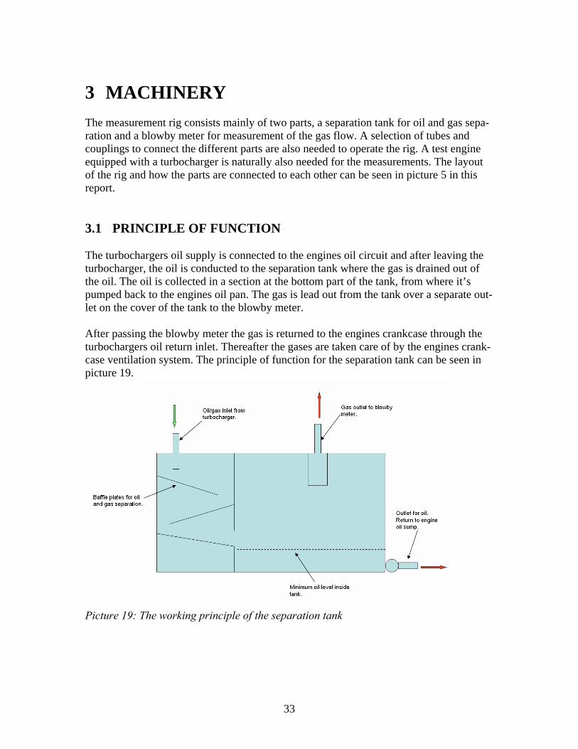
3 MACHINERY The measurement rig consists mainly of two parts, a separation tank for oil and gas sepa-ration and a blowby meter for measurement of the gas flow. A selection of tubes and couplings to connect the different parts are also needed to operate the rig. A test engine equipped with a turbocharger is naturally also needed for the measurements. The layout of the rig and how the parts are connected to each other can be seen in picture 5 in this report. 3.1 PRINCIPLE OF FUNCTION The turbochargers oil supply is connected to the engines oil circuit and after leaving the turbocharger, the oil is conducted to the separation tank where the gas is drained out of the oil. The oil is collected in a section at the bottom part of the tank, from where it’s pumped back to the engines oil pan. The gas is lead out from the tank over a separate out-let on the cover of the tank to the blowby meter. After passing the blowby meter the gas is returned to the engines crankcase through the turbochargers oil return inlet. Thereafter the gases are taken care of by the engines crank-case ventilation system. The principle of function for the separation tank can be seen in picture 19.
Picture 19: The working principle of the separation tank
33

3.2 THE SEPARATION TANK
Picture 20: Separation tank Length: 700 mm. Width: 400 mm. Height (without carriage): 375 mm. The tank is made of stainless steel and has a removable cover which is fastened with 14 M6-screws to a flange on the tank. The separation system inside the tank consists of a system of baffles and a welded plate crossing the shorter side of the tank. The plate di-vides the inside of the tank into two compartments, as can be seen in picture 19. The oil is forced to the surface when passing the plate, which improves the drainment of the gas in the oil. The system of baffle plates can easily be removed from the tank to facilitate cleaning or other usage of the tank. The tank also has two compartments located on both of the long sides which the oil can not enter, as seen in picture 21. The function of these compartments is to decrease the volume of the tank, and to facilitate the pumping because a certain volume of oil in-creases the level in a smaller tank. This gives a more accurate reading on the level switch that controls the pump. The dimensions of these compartments are 300x180x260 mm and 160x110x26 mm. The oil is lead to the tank through the cover by a 3/4” connection, and flows through the baffle system with the help of gravity and settles on the bottom where it’s blended with the oil already existing in the tank. The tank should be filled with oil just over the edge of the cross section plate which height is 125 mm. The separation of oil and gas is facilitated when the oil is forced to flow over the plate. The oil level of the tank is also raised more quickly so that one pumping cycle will inhold a lesser oil volume. The amount of oil in the tank is therefore the total volume of the tank with height 125 mm minus the volume of the compartments.
34

lmV k 35035,0125,04,07,0 3tan ==⋅⋅= [6]
lmVcomp 94,61094,6125,0185,03,0 331 =⋅=⋅⋅= − [7]
lmVcomp 2,2102,2125,011,016,0 332 =⋅=⋅⋅= − [8]
( ) ( ) lVVVV compcompkoil 86,252,294,63521tan =+−=+−= [9]
Picture 21: The tank without cover, heating elements, baffle plates and compartments The tank is placed on a carriage to make transportation easier. There is also an outlet on one of the sides of the tank for oil temperature measurement and one on the cover for pressure measurement. These outlets can be plugged when not used to avoid leakage of oil and gas.
3.2.1 RETURNING OIL TO ENGINE After the draining of gas, the oil is collected in the second compartment of the tank, lo-cated on the right side of the tank in picture 21 from where it’s pumped back to the en-gines crankcase24. The pump operates with compressed air and has a displacement of 3 dl per stroke and the maximum capacity of 30 liters per minute. The low side of the pump is drawn to the bottom of the tank and the pump unit is mounted on the cover of the tank. The pump is separated into a drive unit and a fluid unit to avoid the pump unit from over-heating because of the high oil temperature. The fluid part of the pump is equipped with sealings made of Viton and Teflon to handle operating temperatures up to 135°C. An adjustable valve which operates the speed of the pump is placed on the air inlet. The system also has an adjustable pressure regulator to adjust the operating pressure of the pump. 24 See this report picture 5 on page 12 and picture 19 on page 32.
35
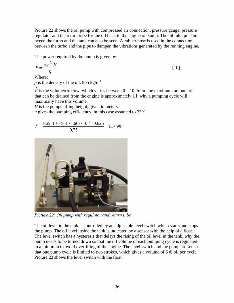
Picture 22 shows the oil pump with compressed air connection, pressure gauge, pressure regulator and the return tube for the oil back to the engine oil sump. The oil inlet pipe be-tween the turbo and the tank can also be seen. A rubber hose is used in the connection between the turbo and the pipe to dampen the vibrations generated by the running engine. The power required by the pump is given by:
ηρ HVgP
•
= [10]
Where: ρ is the density of the oil. 865 kg/m3
•
V is the volumetric flow, which varies between 0 – 10 l/min. the maximum amount oil that can be drained from the engine is approximately 1 l, why a pumping cycle will maximally have this volume. H is the pumps lifting height, given in meters. η gives the pumping efficiency, in this case assumed to 75%
WP 9,11775,0
625,010667,181,910865 53
=⋅⋅⋅⋅⋅
=−
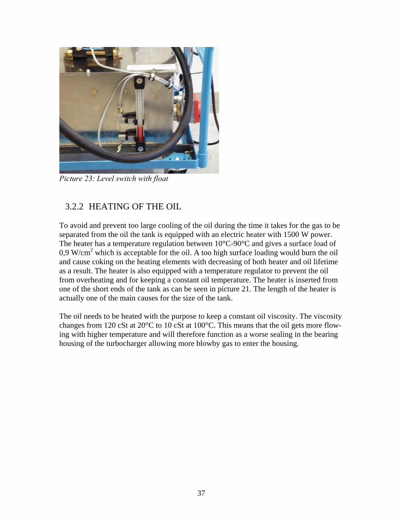
Picture 22: Oil pump with regulator and return tube The oil level in the tank is controlled by an adjustable level switch which starts and stops the pump. The oil level inside the tank is indicated by a sensor with the help of a float. The level switch has a hysteresis that delays the rising of the oil level in the tank, why the pump needs to be turned down so that the oil volume of each pumping cycle is regulated to a minimun to avoid overfilling of the engine. The level switch and the pump are set so that one pump cycle is limited to two strokes, which gives a volume of 6 dl oil per cycle. Picture 23 shows the level switch with the float.
36
Picture 23: Level switch with float
3.2.2 HEATING OF THE OIL To avoid and prevent too large cooling of the oil during the time it takes for the gas to be separated from the oil the tank is equipped with an electric heater with 1500 W power. The heater has a temperature regulation between 10°C-90°C and gives a surface load of 0,9 W/cm2 which is acceptable for the oil. A too high surface loading would burn the oil and cause coking on the heating elements with decreasing of both heater and oil lifetime as a result. The heater is also equipped with a temperature regulator to prevent the oil from overheating and for keeping a constant oil temperature. The heater is inserted from one of the short ends of the tank as can be seen in picture 21. The length of the heater is actually one of the main causes for the size of the tank. The oil needs to be heated with the purpose to keep a constant oil viscosity. The viscosity changes from 120 cSt at 20°C to 10 cSt at 100°C. This means that the oil gets more flow-ing with higher temperature and will therefore function as a worse sealing in the bearing housing of the turbocharger allowing more blowby gas to enter the housing.
37

38
4 TESTING The purpose of the tests is to verify the functionality of the rig and to determine if the blowby through the turbocharger can be measured with the method and the equipment used. To verify a positive functionality of the rig, the tests must confirm that:
1. The separation of the gases from the engine oil is efficient enough. 2. The flow of blowby gases can be measured. 3. The pumping system of the tank must provide the test engine with the oil it needs
for function.
The measurements should also give information of how the turbocharger blowby changes with engine speed and torque. It is also interesting for confirmation of functionality to determine if the measurement rig has an influence on the total blowby of the engine. To confirm the functionality of the rig the tests are basically done by measuring the blowby in the turbocharger by itself and the measuring the total blowby of the engine in-cluding the turbocharger. Finally the blowby of both the engine and the part from the tur-bocharger are measured simultaneously. 4.1 MEASUREMENT OF TURBOCHARGER BLOWBY There are two possible options in connecting the piping between the blowby meter and the engine and both options are tested and the results compared.
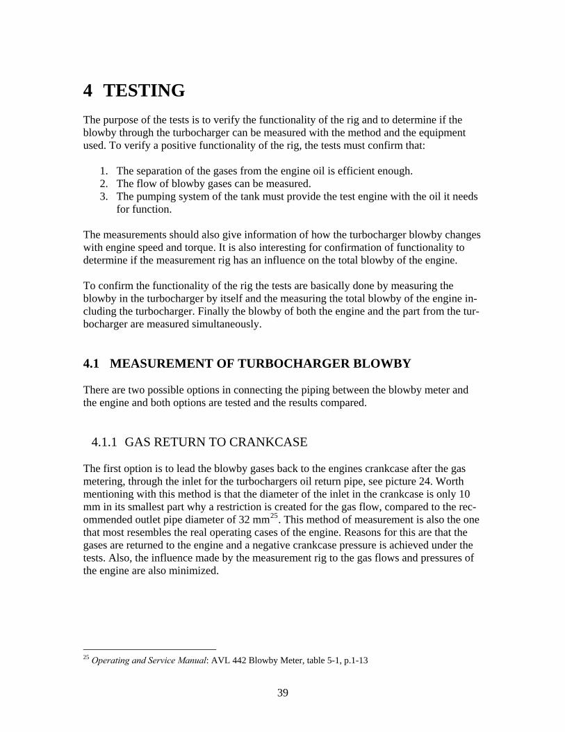
4.1.1 GAS RETURN TO CRANKCASE The first option is to lead the blowby gases back to the engines crankcase after the gas metering, through the inlet for the turbochargers oil return pipe, see picture 24. Worth mentioning with this method is that the diameter of the inlet in the crankcase is only 10 mm in its smallest part why a restriction is created for the gas flow, compared to the rec-ommended outlet pipe diameter of 32 mm25. This method of measurement is also the one that most resembles the real operating cases of the engine. Reasons for this are that the gases are returned to the engine and a negative crankcase pressure is achieved under the tests. Also, the influence made by the measurement rig to the gas flows and pressures of the engine are also minimized.
25 Operating and Service Manual: AVL 442 Blowby Meter, table 5-1, p.1-13
39
Picture 24: Gas return to crankcase
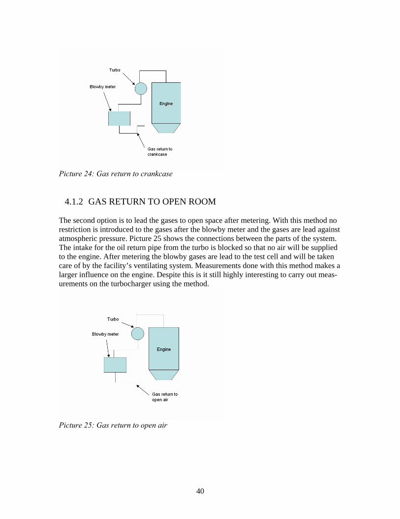
4.1.2 GAS RETURN TO OPEN ROOM The second option is to lead the gases to open space after metering. With this method no restriction is introduced to the gases after the blowby meter and the gases are lead against atmospheric pressure. Picture 25 shows the connections between the parts of the system. The intake for the oil return pipe from the turbo is blocked so that no air will be supplied to the engine. After metering the blowby gases are lead to the test cell and will be taken care of by the facility’s ventilating system. Measurements done with this method makes a larger influence on the engine. Despite this is it still highly interesting to carry out meas-urements on the turbocharger using the method.
Picture 25: Gas return to open air
40
4.2 MEASUREMENT OF ENGINE BLOWBY For measurements of the total engine blowby a specified test procedure, GMPTE-F MEC001 that defines the method to measure the volumetric blowby flow of an engine on a test bench was implemented. The method uses the same procedure as for measurements of the turbocharger blowby. When measuring the engine blowby the same type of blowby meter was used as for the turbocharger measurements. When measuring both blowby flows simultaneously two meters were used.
4.2.1 ENGINE PREPARATIONS On the L850 engine the crankcase ventilation system (PVC system) has two separate cir-cuits that need to be blocked. The first circuit is located at the engine intake manifold and the second goes from the crankcase to the compressor housing on the turbocharger. By doing this the blowby gases can be collected in the crankcase and ventilated through the oil filler cap with a hose to the blowby meter. Worth mentioning is also that the gases are always lead to open air after the flow measurement. 4.3 THE TEST OBJECTIVE
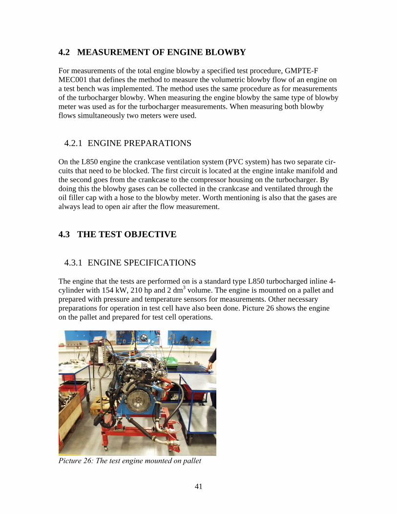
4.3.1 ENGINE SPECIFICATIONS The engine that the tests are performed on is a standard type L850 turbocharged inline 4-cylinder with 154 kW, 210 hp and 2 dm3 volume. The engine is mounted on a pallet and prepared with pressure and temperature sensors for measurements. Other necessary preparations for operation in test cell have also been done. Picture 26 shows the engine on the pallet and prepared for test cell operations.
Picture 26: The test engine mounted on pallet
41
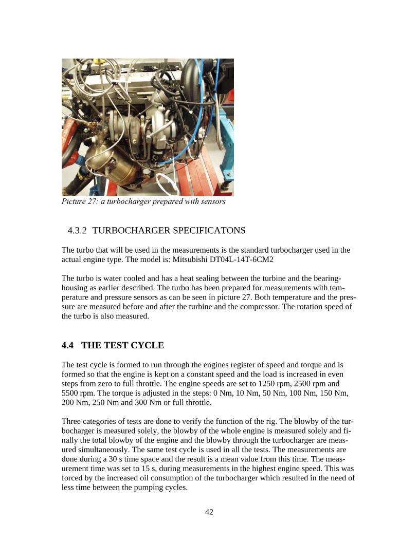
Picture 27: a turbocharger prepared with sensors
4.3.2 TURBOCHARGER SPECIFICATONS The turbo that will be used in the measurements is the standard turbocharger used in the actual engine type. The model is: Mitsubishi DT04L-14T-6CM2 The turbo is water cooled and has a heat sealing between the turbine and the bearing-housing as earlier described. The turbo has been prepared for measurements with tem-perature and pressure sensors as can be seen in picture 27. Both temperature and the pres-sure are measured before and after the turbine and the compressor. The rotation speed of the turbo is also measured. 4.4 THE TEST CYCLE The test cycle is formed to run through the engines register of speed and torque and is formed so that the engine is kept on a constant speed and the load is increased in even steps from zero to full throttle. The engine speeds are set to 1250 rpm, 2500 rpm and 5500 rpm. The torque is adjusted in the steps: 0 Nm, 10 Nm, 50 Nm, 100 Nm, 150 Nm, 200 Nm, 250 Nm and 300 Nm or full throttle. Three categories of tests are done to verify the function of the rig. The blowby of the tur-bocharger is measured solely, the blowby of the whole engine is measured solely and fi-nally the total blowby of the engine and the blowby through the turbocharger are meas-ured simultaneously. The same test cycle is used in all the tests. The measurements are done during a 30 s time space and the result is a mean value from this time. The meas-urement time was set to 15 s, during measurements in the highest engine speed. This was forced by the increased oil consumption of the turbocharger which resulted in the need of less time between the pumping cycles.
42
4.4.1 MEASURED VARIABLES
The most interesting variables measured are: Engine speed [1/min] Engine torque [Nm] Crankcase pressure [kPa] Oil pressure [kPa] Blowby flow in turbocharger [l/min] Blowby flow in engine [l/min] Other variables that grant normal operation of the engine are monitored during testing to avoid engine breakdown. The complete list of measured variables including associated units can be seen in the test engine documentation for test engine FMPG0618.
43

44
5 RESULTS 5.1 THE ACCOMPLISHED TESTS The total number of specific tests executed was 8, divided into totally 23 test cycles. All the test results obtained are documented according to set routines at GM Powertrain Sweden AB. The tests were:
1. Measurement of blowby through the turbocharger with 75 l/min pipe. Gas return against crankcase.
2. Measurement of blowby through the turbocharger with 150 l/min pipe. Gas return against crankcase.
3. Measurement of the engines total blowby and turbocharger blowby, both against atmospheric pressure.
4. Measurement of turbocharger blowby against atmospheric pressure with 150 l/min pipe.
5. Measurement of turbocharger blowby against atmospheric pressure with 75 l/min pipe.
6. Measurement of total blowby of the engine with 75 l/min. pipe. 7. Measurement of total blowby of the engine with 150 l/min. pipe. 8. Measurement of the engines total blowby against atmospheric pressure and turbo-
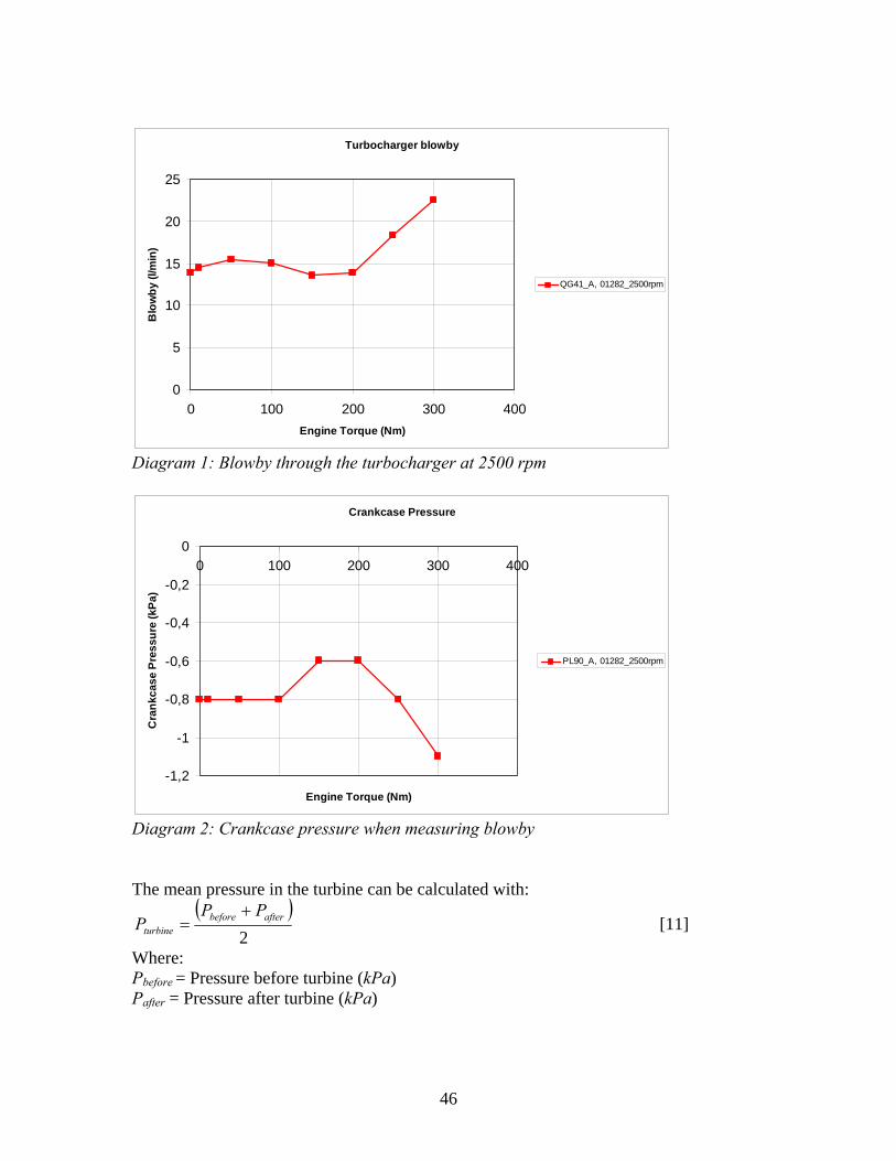
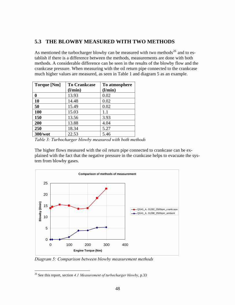
charger blowby with gas return to crankcase. The pumping cycle causes disturbance in the metering and affects the crankcase pressure. This is caused by the fact that the volume in the tank is changed during the pumping cy-cle. The difference in oil level is only approximately 10 mm when the pump is turned on and off, but it has a large effect on the pressure why the measurements are timed to take place between two cycles. This fact also motivates the shorter measurement period of 15 s when measuring with engine speed 5500 rpm. 5.2 TURBOCHARGER BLOWBY The first measurement is planned to answer the question if the blowby through the turbo-charger can be measured with the rig. The results show that the blowby flow increases with higher engine torque. One of the parameters that affect the blowby is the crankcase pressure. Diagram 1 shows the turbocharger blowby as a function of the engine torque. This specific measurement was done with the oil return pipe connected to the crankcase and the actual engine speed was 2500 rpm. The dip in diagram 1 has a related opposite rising in the crankcase pressure as seen in diagram 2. The pressure difference between the turbine and the crankcase functions as the driving force in the system and has therefore a large influence on the blowby.
45
Turbocharger blowby
0
5
10
15
20
25
0 100 200 300 400Engine Torque (Nm)
Blo
wby
(l/m
in)
QG41_A, 01282_2500rpm
Diagram 1: Blowby through the turbocharger at 2500 rpm
Crankcase Pressure
-1,2
-1
-0,8
-0,6
-0,4
-0,2
00 100 200 300 400
Engine Torque (Nm)
Cra
nkca
se P
ress
ure
(kPa
)
PL90_A, 01282_2500rpm
Diagram 2: Crankcase pressure when measuring blowby The mean pressure in the turbine can be calculated with:
( )2
afterbeforeturbine
PPP
+= [11]
Where: Pbefore = Pressure before turbine (kPa) Pafter = Pressure after turbine (kPa)
46

The pressure difference in the system is:
( )crankcase
afterbeforediff P
PPP −
+=
2 [12]
The blowby plotted with the pressure difference shows that the blowby follows the same trend as for the plot with the crankcase pressure, as can be seen in diagram 3.
Turbocharger blowby and Pressure difference
0
5
10
15
20
25
0 10 20 30 40Pressure difference in system (kPa)
Blo
wby
in tu
rboc
harg
er (l
/min
)
QG41_A, 01282_2500rpm
Diagram 3: Turbocharger blowby as a function of the pressure difference The engine speed has an influence on the amount of blowby flow in the turbo, as can be seen in diagram 4. It can be observed that at zero loads there is not particular difference in flow rates between the speeds.
Turbocharger blowby with different engine speeds
-20
-10
0
10
20
30
40
50
60
70
0 100 200 300 400
Engine Torque (Nm)
Blo
wby
(l/m
in) QG41_A, 01281_1250rpm_turbo
blowbyQG41_A, 01282_2500rpm_turboblowbyQG41_A, 01283_5500rpm_turboblowby
Diagram 4: Blowby in the turbocharger with different engine speeds
47
5.3 THE BLOWBY MEASURED WITH TWO METHODS As mentioned the turbocharger blowby can be measured with two methods26 and to es-tablish if there is a difference between the methods, measurements are done with both methods. A considerable difference can be seen in the results of the blowby flow and the crankcase pressure. When measuring with the oil return pipe connected to the crankcase much higher values are measured, as seen in Table 1 and diagram 5 as an example. Torque [Nm] To Crankcase
(l/min) To atmosphere (l/min)
0 13.93 0.02 10 14.48 0.02 50 15.49 0.02 100 15.03 1.1 150 13.56 3.93 200 13.88 4.04 250 18.34 5.27 300/wot 22.53 5.46 Table 3: Turbocharger blowby measured with both methods The higher flows measured with the oil return pipe connected to crankcase can be ex-plained with the fact that the negative pressure in the crankcase helps to evacuate the sys-tem from blowby gases.
Comparison of methods of measurement
0
5
10
15
20
25
0 100 200 300 400Engine Torque (Nm)
Blo
wby
(l/m
in)
QG41_A, 01282_2500rpm_crankcaseQG41_A, 01288_2500rpm_ambient
Diagram 5: Comparison between blowby measurement methods 26 See this report, section 4.1 Measurement of turbocharger blowby, p.33
48
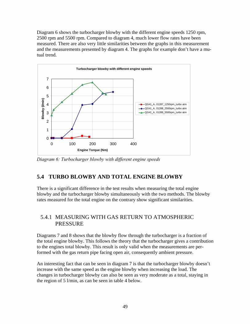
Diagram 6 shows the turbocharger blowby with the different engine speeds 1250 rpm, 2500 rpm and 5500 rpm. Compared to diagram 4, much lower flow rates have been measured. There are also very little similarities between the graphs in this measurement and the measurements presented by diagram 4. The graphs for example don’t have a mu-tual trend.
Turbocharger blowby with different engine speeds
0
1
2
3
4
5
6
7
0 100 200 300 400Engine Torque (Nm)
Blo
wby
(l/m
in)
QG41_A, 01287_1250rpm_turbo atmQG41_A, 01288_2500rpm_turbo atmQG41_A, 01289_5500rpm_turbo atm
Diagram 6: Turbocharger blowby with different engine speeds 5.4 TURBO BLOWBY AND TOTAL ENGINE BLOWBY There is a significant difference in the test results when measuring the total engine blowby and the turbocharger blowby simultaneously with the two methods. The blowby rates measured for the total engine on the contrary show significant similarities.
5.4.1 MEASURING WITH GAS RETURN TO ATMOSPHERIC PRESSURE
Diagrams 7 and 8 shows that the blowby flow through the turbocharger is a fraction of the total engine blowby. This follows the theory that the turbocharger gives a contribution to the engines total blowby. This result is only valid when the measurements are per-formed with the gas return pipe facing open air, consequently ambient pressure. An interesting fact that can be seen in diagram 7 is that the turbocharger blowby doesn’t increase with the same speed as the engine blowby when increasing the load. The changes in turbocharger blowby can also be seen as very moderate as a total, staying in the region of 5 l/min, as can be seen in table 4 below.
49
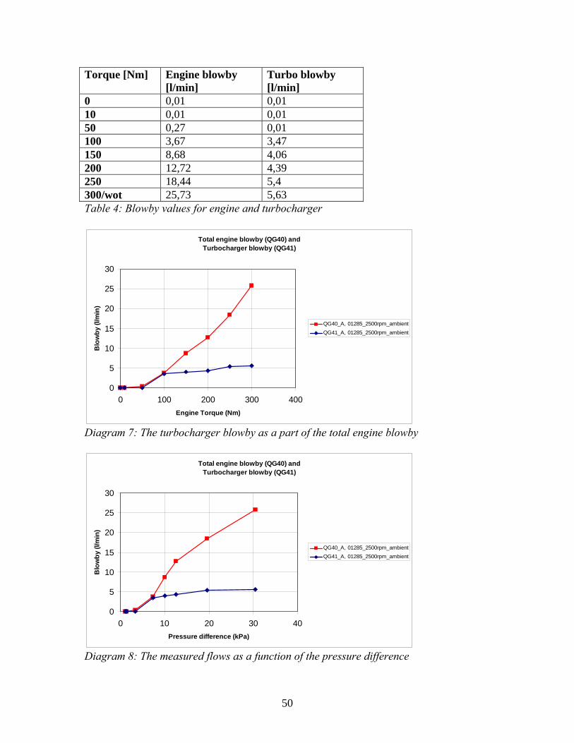
Torque [Nm] Engine blowby [l/min]
Turbo blowby [l/min]
0 0,01 0,01 10 0,01 0,01 50 0,27 0,01 100 3,67 3,47 150 8,68 4,06 200 12,72 4,39 250 18,44 5,4 300/wot 25,73 5,63 Table 4: Blowby values for engine and turbocharger
Total engine blowby (QG40) and Turbocharger blowby (QG41)
0
5
10
15
20
25
30
0 100 200 300 400Engine Torque (Nm)
Blo
wby
(l/m
in)
QG40_A, 01285_2500rpm_ambientQG41_A, 01285_2500rpm_ambient
Diagram 7: The turbocharger blowby as a part of the total engine blowby
Total engine blowby (QG40) andTurbocharger blowby (QG41)
0
5
10
15
20
25
30
0 10 20 30 40Pressure difference (kPa)
Blo
wby
(l/m
in)
QG40_A, 01285_2500rpm_ambientQG41_A, 01285_2500rpm_ambient
Diagram 8: The measured flows as a function of the pressure difference
50

When measuring both blowby flows at the same time, no flow rates can be detected on lower loads on engine speeds 1250 rpm and 2500 rpm. When running 5500 rpm a flow can be measured throughout the whole register. The measured results for the three engine speeds can be seen in table 5 and diagram 9. In this measurement the turbocharger blowby was measured against atmospheric pressure. Torque [Nm] 1250 [rpm] 2500 [rpm] 5500 [rpm] 0 0 0 0 10 0 0 0,61 50 0 0 3,96 100 0 3,47 5,21 150 0,43 4,06 6,09 200 3,41 4,39 6,5 250 - 5,4 7,74 300/wot - 5,63 8,71 Table 5: Turbocharger blowby with different engine speeds
Turbocharger blowby with different engine speeds
0123456789
10
0 100 200 300 400Engine Torque (Nm)
Blo
wby
(l/m
in)
QG41_A, 01284_1250rpm_turbo
QG41_A, 01285_2500rpm_turboQG41_A, 01286_5500rpm_turbo
Diagram 9: turbocharger blowby with different engine speeds
5.4.2 MEASURING WITH GAS RETURN TO CRANKCASE Different results are gained when the other method of measurement for the turbocharger is applied. The only case when a blowby flow can be measured is at 5500 rpm and from 150 Nm and upwards. No indication of flow could be measured at lower engine speeds or lower torque with this method. A comparison between the blowby flows can be seen in diagram 10. The QG40 graph shows the total engine blowby and the QG41 graph the turbocharger blowby. The results for the engine blowby looks different for 5500 rpm as can be seen in diagram 11.
51
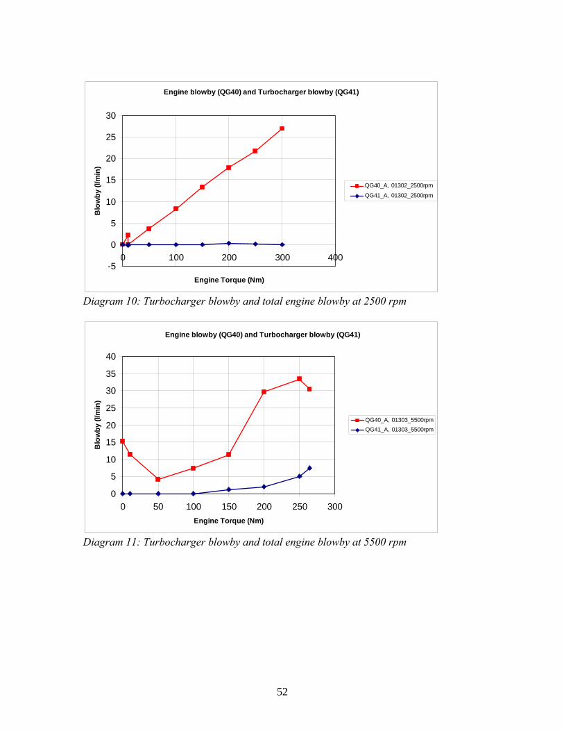
Engine blowby (QG40) and Turbocharger blowby (QG41)
-5
0
5
10
15
20
25
30
0 100 200 300 400
Engine Torque (Nm)
Blo
wby
(l/m
in)
QG40_A, 01302_2500rpm
QG41_A, 01302_2500rpm
Diagram 10: Turbocharger blowby and total engine blowby at 2500 rpm
Engine blowby (QG40) and Turbocharger blowby (QG41)
0
5
10
15
20
25
30
35
40
0 50 100 150 200 250 300Engine Torque (Nm)
Blo
wby
(l/m
in)
QG40_A, 01303_5500rpmQG41_A, 01303_5500rpm
Diagram 11: Turbocharger blowby and total engine blowby at 5500 rpm
52
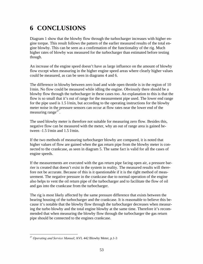
6 CONCLUSIONS Diagram 1 show that the blowby flow through the turbocharger increases with higher en-gine torque. This result follows the pattern of the earlier measured results of the total en-gine blowby. This can be seen as a confirmation of the functionality of the rig. Much higher rates of blowby was measured for the turbocharger than estimated before testing though. An increase of the engine speed doesn’t have as large influence on the amount of blowby flow except when measuring in the higher engine speed areas where clearly higher values could be measured, as can be seen in diagrams 4 and 6. The difference in blowby between zero load and wide open throttle is in the region of 10 l/min. No flow could be measured while idling the engine. Obviously there should be a blowby flow through the turbocharger in these cases too. An explanation to this is that the flow is so small that it’s out of range for the measurement pipe used. The lower end range for the pipe used is 1.5 l/min, but according to the operating instructions for the blowby meter noise in the pressure sensors can occur at flow rates near the lower end of the measuring range27. The used blowby meter is therefore not suitable for measuring zero flow. Besides this, negative flow can be measured with the meter, why an out of range area is gained be-tween -1.5 l/min and 1.5 l/min. If the two methods of measuring turbocharger blowby are compared, it is noted that higher values of flow are gained when the gas return pipe from the blowby meter is con-nected to the crankcase, as seen in diagram 5. The same fact is valid for all the cases of engine speeds. If the measurements are executed with the gas return pipe facing open air, a pressure bar-rier is created that doesn’t exist in the system in reality. The measured results will there-fore not be accurate. Because of this is it questionable if it is the right method of meas-urement. The negative pressure in the crankcase due to normal operation of the engine also helps to vent the oil return pipe of the turbocharger and to facilitate the flow of oil and gas into the crankcase from the turbocharger. The rig is most likely affected by the same pressure difference that exists between the bearing housing of the turbocharger and the crankcase. It is reasonable to believe this be-cause it’s notable that the blowby flow through the turbocharger decreases when measur-ing the turbo blowby and the total engine blowby at the same time. Therefore it’s recom-mended that when measuring the blowby flow through the turbocharger the gas return pipe should be connected to the engines crankcase.
27 Operating and Service Manual; AVL 442 Blowby Meter, p.1-3
53
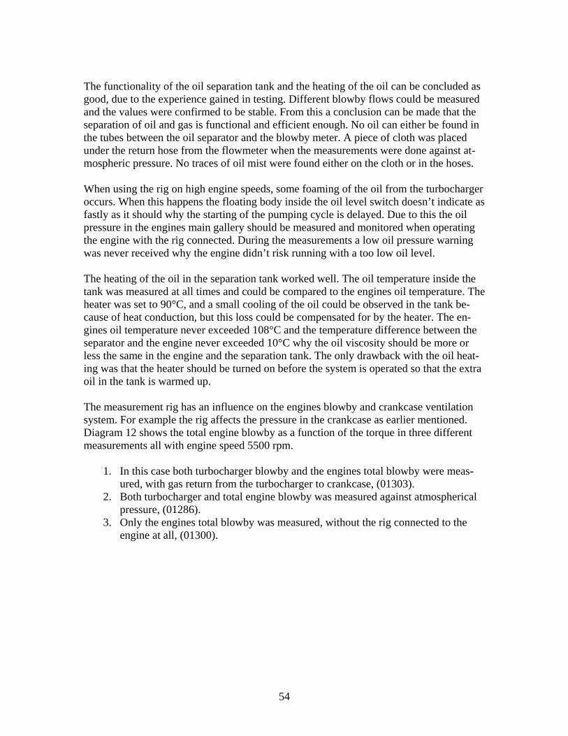
The functionality of the oil separation tank and the heating of the oil can be concluded as good, due to the experience gained in testing. Different blowby flows could be measured and the values were confirmed to be stable. From this a conclusion can be made that the separation of oil and gas is functional and efficient enough. No oil can either be found in the tubes between the oil separator and the blowby meter. A piece of cloth was placed under the return hose from the flowmeter when the measurements were done against at-mospheric pressure. No traces of oil mist were found either on the cloth or in the hoses. When using the rig on high engine speeds, some foaming of the oil from the turbocharger occurs. When this happens the floating body inside the oil level switch doesn’t indicate as fastly as it should why the starting of the pumping cycle is delayed. Due to this the oil pressure in the engines main gallery should be measured and monitored when operating the engine with the rig connected. During the measurements a low oil pressure warning was never received why the engine didn’t risk running with a too low oil level. The heating of the oil in the separation tank worked well. The oil temperature inside the tank was measured at all times and could be compared to the engines oil temperature. The heater was set to 90°C, and a small cooling of the oil could be observed in the tank be-cause of heat conduction, but this loss could be compensated for by the heater. The en-gines oil temperature never exceeded 108°C and the temperature difference between the separator and the engine never exceeded 10°C why the oil viscosity should be more or less the same in the engine and the separation tank. The only drawback with the oil heat-ing was that the heater should be turned on before the system is operated so that the extra oil in the tank is warmed up. The measurement rig has an influence on the engines blowby and crankcase ventilation system. For example the rig affects the pressure in the crankcase as earlier mentioned. Diagram 12 shows the total engine blowby as a function of the torque in three different measurements all with engine speed 5500 rpm.
1. In this case both turbocharger blowby and the engines total blowby were meas-ured, with gas return from the turbocharger to crankcase, (01303).
2. Both turbocharger and total engine blowby was measured against atmospherical pressure, (01286).
3. Only the engines total blowby was measured, without the rig connected to the engine at all, (01300).
54
Comparison of total engine blowby
0
5
10
15
20
25
30
35
40
45
50
0 50 100 150 200 250 300
Engine Torque (Nm)
Engi
ne b
low
by (l
/min
)
QG40_A, 1.01303_5500rpm
QG40_A, 2.01286_5500rpm
QG40_A, 3.01300_5500rpm
Diagram 12: Comparison of total engine blowby The results from diagram 12 show that the two cases where both blowbys were measured, no significant differences can’t be found. In these two cases the measurement rig was in-volved in the measurements. In the third case when measuring the total engine blowby only, a difference compared to the other cases can be found. The value of the difference is the influence that the measurement rig affects the engine with. It can also be noted that the measurement rigs influence is larger in the lower torque areas and is increasing from 10 Nm to 100 Nm, whereupon it decreases. Besides the fact that the measurements have different values, the functions shows distinctly the same trend with a higher start value followed by a dip in the region of 50 Nm whereafter they in-crease similarly. The same form of the diagrams can be seen in earlier performed meas-urements of engine blowby. The diagram also shows that lower values of flow are measured when the rig is used. The main cause for this difference is the pressure drop that takes place in the blowby meter and in the tubing between the separation tank and the flowmeter and likewise between the flowmeter and the engine. The pressure drop can be minimized by shortening the tubes and using as straight tubing as possible. The manual for the blowby meter prescribes as-cending tube into the flowmeter and descending from the meter, which also was used in the measurements28. A conclusion is that the rig has an influence on the blowby system of the engine, but it is limited and can be stated with different measurements as proved.
28 Operating and Service Manual; AVL 442 Blowby meter, p.1-3
55
If comparing the results when first only measuring engine blowby with the specified method to measuring only turbocharger blowby, significant similarities can be seen with the results presented in diagram 7. The turbocharger blowby is a part of the total blowby created in the engine. This result is only valid when measurements are performed with the gas return pipe from turbocharger facing open air, consequently ambient air pressure. The same conclusion is not applicable if the measurements are done with the gas return pipe connected to the engines crankcase. Earlier it could be noticed that the turbocharger blowby in this case was difficult to measure simultaneously with the engine blowby, as shown in diagram 10. The same conclusion is valid in this application. Another conclusion that can be drawn from the results is that it is not recommended to measure the turbo blowby at the same time as the engine blowby is measured. None of the methods for measuring turbo blowby was able to measure flow through the turbo at lower loads at engine speed 1250 rpm and 2500 rpm, witch was stated in sections 5.4.1 and 5.4.2. When the turbo is measured separately a flow can be measured even in these cases, as can be seen in diagram 5. Therefore performing measurements with the engine and the turbo simultaneously gives misleading results that without exception are too low. A rea-son for this is that the measurements are done with two different conditions. In the first case the blowby is measured with ambient pressure in the crankcase and in the second case a negative pressure as in normal engine operations is present. To sum up, if the specified method for measuring engine blowby is applied, the turbo-charger blowby should not be measured at the same time, because the values are not ac-curate enough.
56

57
7 RECOMMENDATIONS AND FURTHER WORK
◊ It should be further investigated if there is an alternative method for measuring
the engine blowby. This method should preferably not apply ambient pressure in the engine crankcase. It would be interesting to compare the results between the two methods.
◊ The measurements should be performed throughout the engines whole speed reg-
ister in narrower spacing, similar to the blowby mappings. From 0 to full speed with 500 rpm spacing. The torque should also be increased in steps of 10 Nm or 20 Nm instead of 50 Nm.
◊ If a more accurate controlling of the oil pumping back to the engine is wished, the
limit switches should be changed to a type that indicates on a smaller oil level change in the tank.
◊ There must be a flexible connection between the engine and the separation tank
sothat the vibrations generated by the engine is not transformed to the tank.
◊ The rack of baffle-sheets is not fastened to the tank so that it can be lifted out if another solution for separation is wished.
◊ The pump has a much higher capacity that is needed for the volumes in question
for the different engine types why it needs to be turned down.
◊ It is highly recommended that in the case of changing the pump to use a pump that operates on compressed air rather than electricity. By doing so the possible electrical disturbances caused by the pump-unit to the blowby meter is eliminated.
58

59
8 ACKNOWLEDGEMENTS
The author of this thesis would like to thank the following people:
◊ Anders Gawell at GM Powertrain Sweden AB for excellent tutoring and guid-ance.
◊ Eric Olofsson at GM Powertrain Sweden AB for initiating this thesis.
◊ Priidu Pukk at KTH Machine design who has been my supervisor during the
work. ◊ Mikael Gellerstedt and Daniel Danielsson, both at GM Powertrain Sweden
AB for great support and giving me ideas.
◊ Karl-Wilhelm Ståhle at GM Powertrain Sweden AB for all the help in getting started with testing.
◊ Mika Heinonen and Lars Karlsson at the workshop for the superb mechanics.
◊ Christer Forslund at GM Powertrain Sweden AB for the Analyzer tool and
Excel expertise.
◊ All those who has shown interest for this thesis and contributed with good and bad ideas.
60

61
9 References R. Pritchard, Guy J.J, Connor N.E. Handbook of Industrial Gas Utilization, Van Nostrand & Reinhold Company, British Gas Corporation 1977 ISBN: 0-442-26635-9 Alvarez H., Energiteknik Del 1, Studentlitteratur 1990 ISBN 91-44-31471-x Heywood J.B. Internal Combustion Engine Fundamentals, McGraw – Hill Book Co. 1988 ISBN 0-07-100499-8 Hoffman A.C. Stein L.E. Gas Cyclones and Swirl Tubes, Springer Verlag 2002 ISBN 3-540-43326-0 Bell C. Maximum Boost, Designing, Testing and Installing Turbocharger Systems, Motor Racing Publications Limited 1997 ISBN 1-899870-23-7 Heisler H. Advanced Engine Technology, SAE International 1995 ISBN 1-56091-7342 Project report BLT010, Centrifugalseparering, Lunds Tekniska Högskola 2006 FTI Flow Technology (www.ftimeters.com) Spirax – Sarco Limited (www.spiraxsarco.com/learn/modules/4_3_01.asp) Sierra Instruments Inc. (www.sierrainstruments.com/products) Brooks Instruments Inc. (www.emersonprocess.com/brooks/products) Amistco Corp. (www.amistco.com/products/eliminators/msh_eliminators) Amistco Corp. (www.amistco.com/BULLS_PDF/meshvaneSM.pdf)
62

63
APPENDIX 1 SPECIFICATION OF REQUIREMENTS
1 The measurement rig will only be used in the engine test cells. 2 A measurement range that includes all present engine types provided by GM
Powertrain Sweden AB must be provided for with the used flowmeter.
3 All present engines must be mechanically applicable to the measurement rig.
4 No changes on the engine pallets or any auxiliary equipment used in the test cells can be done because of the size or form of the rig.
5 The total cost for the measurement rig must not exceed the set frames.
6 Measurement of pressure, temperature and flow rate of gas and oil must be
possible in the rig.
7 Different types of turbochargers provided by the different suppliers should be measured with the rig with minimum of rebuilding.
64

APPENDIX 2 SPECIFICATION OF REQUIREMENTS: FLOW MEASUREMENT
1 The measurement of the blowby flow must have accuracy with a deviation of maximum 2% of the total measured flow.
2 Range of measurement for the flowmeter has to be 0 – 30 l/min.
3 Calibration of the flowmeter used in the rig has to be possible.
4 High gas temperatures and gas possibly soiled with oil mist has to be handled
by the flowmeter.
5 It has to be possible to change the measurement range of the flowmeter with kept accuracy.
6 The flowmeter may not cause any disturbances to the engine or other measur-
ing equipment used in the engine test cells.
65
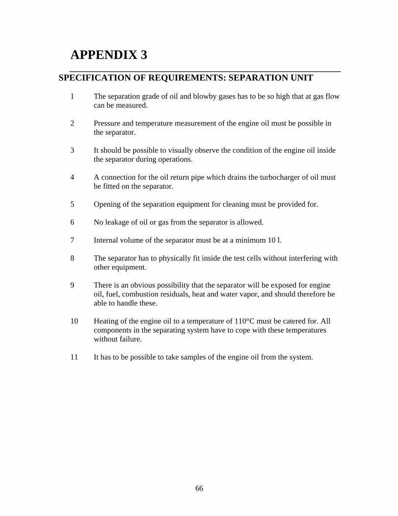
APPENDIX 3
SPECIFICATION OF REQUIREMENTS: SEPARATION UNIT
1 The separation grade of oil and blowby gases has to be so high that at gas flow can be measured.
2 Pressure and temperature measurement of the engine oil must be possible in
the separator.
3 It should be possible to visually observe the condition of the engine oil inside the separator during operations.
4 A connection for the oil return pipe which drains the turbocharger of oil must
be fitted on the separator.
5 Opening of the separation equipment for cleaning must be provided for.
6 No leakage of oil or gas from the separator is allowed.
7 Internal volume of the separator must be at a minimum 10 l.
8 The separator has to physically fit inside the test cells without interfering with other equipment.
9 There is an obvious possibility that the separator will be exposed for engine
oil, fuel, combustion residuals, heat and water vapor, and should therefore be able to handle these.
10 Heating of the engine oil to a temperature of 110°C must be catered for. All
components in the separating system have to cope with these temperatures without failure.
11 It has to be possible to take samples of the engine oil from the system.
66
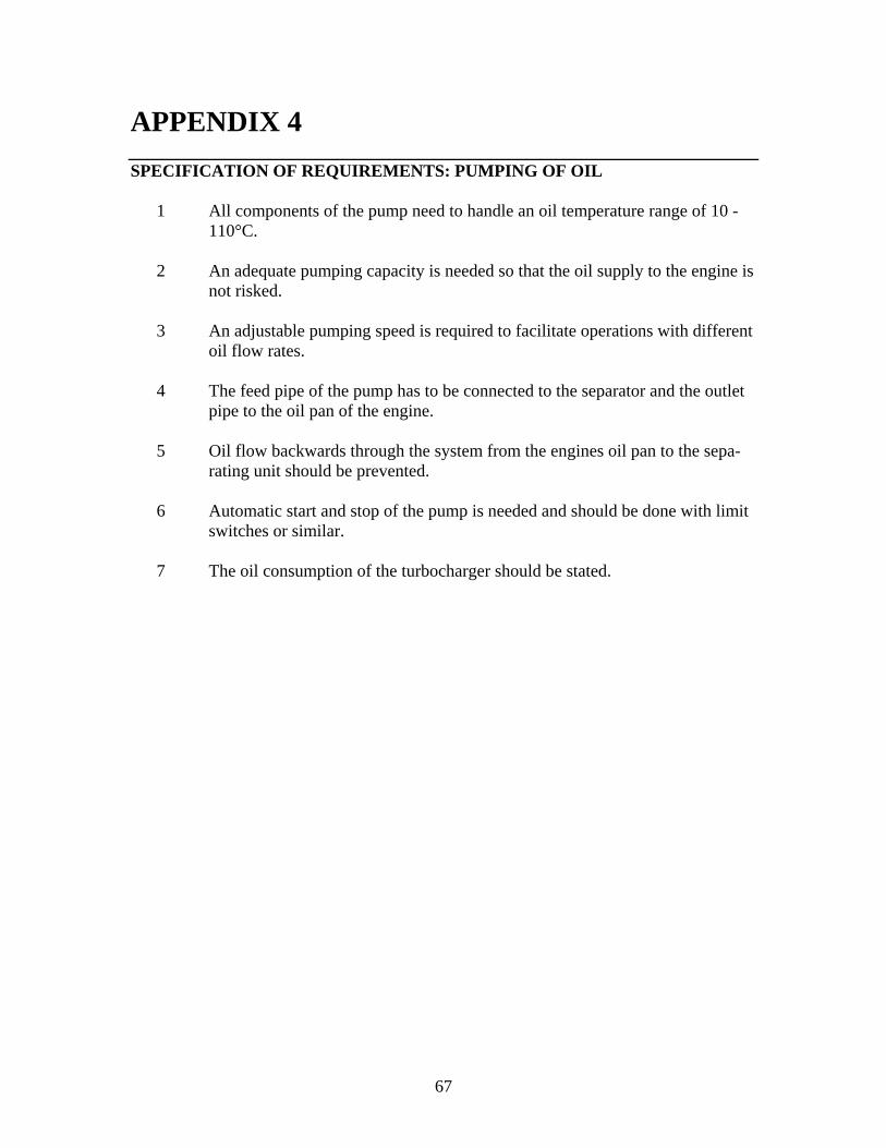
APPENDIX 4 SPECIFICATION OF REQUIREMENTS: PUMPING OF OIL
1 All components of the pump need to handle an oil temperature range of 10 - 110°C.
2 An adequate pumping capacity is needed so that the oil supply to the engine is
not risked.
3 An adjustable pumping speed is required to facilitate operations with different oil flow rates.
4 The feed pipe of the pump has to be connected to the separator and the outlet
pipe to the oil pan of the engine.
5 Oil flow backwards through the system from the engines oil pan to the sepa-rating unit should be prevented.
6 Automatic start and stop of the pump is needed and should be done with limit
switches or similar.
7 The oil consumption of the turbocharger should be stated.
67