Embed Size (px)
Citation preview

Measurement of Elastic and Strength Properties of Cemented Materials in Road Bases R. JONES, Road Research Laboratory, Department of Scientific and Industrial
Research, Great Britain
•MEASUREMENTS of the elastic properties of lean concrete and cement-stabilized materials, i.e., cemented materials in the bases or subbases of flexible roads, are useful for three main reasons.
1. A knowledge of the elastic properties and the thicknesses of the constituent layers of a road permits calculation of the stresses arising in the road from traffic loading (1).
2. There is usually an empirical relationship between the modulus of elasticity and the strength of a cemented material (2). Thus, in situ measurements of the elastic properties of a cemented base or subbase can provide an estimate of its strength and give an indication of whether the material is likely to fail under the stresses previously cited.
3. Changes in the elastic properties of cemented layers of a road with time and traffic indicate whether or not severe deterioration has occurred (~).
The considerably reduced value of the elastic modulus obtained from measurements on roads having badly cracked cemented bases has permitted more realistic computations (1) to be made of the stresses which will develop in other parts of the road when the design criteria allow cracking to occur.
This paper gives the results of measurements of the dynamic elastic properties and the compressive and flexural strengths of laboratory specimens of cemented materials of the type used in road bases and subbases.
A surface wave propagation method is described for measuring the in situ modulus of elasticity of cemented layers of a road. Estimates of the strength of the uncracked materials are made from empirical relations of the type discussed in the next section.
The paper discusses repetitive measurements at the surface of a road by the surfacewave propagation method to study the changes in the elastic properties of cemented bases. The influence of the results of these measurements on design criteria for cemented layers of a road is discussed briefly later.
LABORATORY EXPERIMENTS ON TEST SPECIMENS
Experimental Procedure
Resonance and pulse methods (2) are used to obtain the dynamic Young's modulus and Poisson's ratio of test specimens that are subsequently broken to give the compressive or flexural strength of the material. The measurements of the longitudinal resonant frequency and pulse velocity are made by techniques which are now widely used for test specimens of normal concrete and which are fully described elsewhere (2).
The fundamental resonant frequency (n0 ) of a cylinder or prism in its longitudinal mode of vibration is related to the dynamic Young's modulus (E) of the material by the relation:
Paper sponsored by Committee on Soi I-Portland Cement Stabilization and presented at the 45th Annual Meeting.
101
(1)

102
where
p g 1
Tt
bulk density of specimen, acceleration due to gravity, length of specimen, and a factor to correct for finite cross-section of specimen (2). (In the present experiments T.i, has a maximum value of about 1. 05.) -
Eq. 1 allows E to be calculated when p, n0 , 1 and T.i, are known. When a comparison is made with in situ tests on road bases, it is more convenient to work with the
y, parameter (gE/ p) 2 as explained later.
The pulse veiocity a in the specimen is relaied io ihe elastic moduli by the relation:
(2)
where vis Poisson's ratio calculated from Eqs. 1 and 2 and n0 , 1, Tt and a are known.
30
"' '= ' ~
·o
I >-':: ~ 2·0 f-VJ <t ...J w u.. 0 VJ :::> -' :::> 0 0 2
.VJ (') z
1·0 :::> 0 >-u ~ <t z >-0
0
0
Q
0
0
500
--• - Silty sand, type A
-o-Silty sand . type B
1000
6 Sand /\ Sandy silt
o Clay
1500
COMPRESSIVE STRENG I H - I b / in 7
0
Figure 1. Relation between dynamic Young's modulus and compressive strength of different types of soi I cement (fine-grained soi Is).

103
TABLE 1
CHARACTERISTICS OF SOILS USED IN INVESTIGATION FOR FIGURES 1 AND 2
Br itish Standard
Particle Size Distribution Index Tests Compaction Test
Casagrande {B . S. 1377: 1948) Soil Type Class. Gravel Sand Silt Clay L.L. P.L. P .I.
(%) (%\ (%) (%) (%) (%) (%) Max. Dry Opt. Moist. Density Content
(pcf) (%)
Sandy grave l GF 52 28 13 7 Nonplastic 128 Hr Sand SU 95 2 3 Nonplastic 113 12 Silty sand (A) CL 6 57 29 8 21 15 6 126 10 Silty sand (B) CL 56 31 13 26 15 11 119 12 Sand silt CL 25 60 15 31 18 13 113 15 Clay CH 30 23 47 65 20 45 92 24
Results
The relation between the dynamic Young's modulus and the compressive strength of soil-cement containing fine-grained soils is shown in Figure 1; details of the various soils are given in Table 1. The relation between the dynamic Young's modulus and the flexural strength of the soil cements is shown in Figure 2. The results show that the
30
"' c
D
"'o
>- 2 0 I-
u I-I/) <(
--' w
u. 0 I/)
=> --' => 0 0 }:
I/) 1· 0 .l? z => 0 >-u ~ <( z >-0
0
• Silty sand , type A
O Silty sand , type B
• Sand
b Sa ndy silt
D Clay
100
0
FLEXURAL STRENGTH - lb/in 2
• • • •
200
Figure 2. Relation between dynamic Young's modulus and flexural strength of different types of soil cement (fine-grained soi Is).

104
6
"' c .:::: fl 5 .. Q I
>-~ \,! 4 I-t/)
<l: --' w "-0 3 t/) :::J --' :::J 0 0 ~ 2 t/)
·19 z 6 >-\,! 1 }: <l: z >-0
0
• • • •
... ...
...... .. .. ... t .....
... .....
•
~- . . ... •c •••.• • •••
~" p._. ~ .. " • oc
•
100 200
•
300
• Cemented granular base A
0 Cemented granular base B
.& Lean- concrete base C
400 500 600 F LEXURAL STRENGTH-lb/in1
Figure 3. Relation between dynamic Young's modulus of elast icity and flexural strength of cemented base materials.
dynamic modulus varied between about 0. 5 x 10⁶ psi and 2. O x 106 psi; in the case of soil-cement made from silty sand, type B, the variations were produced by changing the dry density, cement content, moisture content and age of test. Figures 1 and 2 show that the relations between dynamic modulus of elasticity and either compressive or flexural strength for the soil-cement containing silty sand, type B, were relatively insensitive to the variations in composition or age of test; changes in soil type often produced significant deviations from these relations.
Results obtained for the dynamic Young's modulus of elasticity and the flexural strength of cemented base materials containing gravel aggregate to a maximum size of about 1 % in. are shown in Figure 3. Bases A and B contained "as-dug" aggregate and conformed to an outdated specification for cement-bound granular base material, whereas base C contained washed and graded aggregate, and the material conformed to the specification for lean concrete given later. The results (Fig. 3) were obtained on beams cut from the bases, and there is an approximate relation between the dynamic modulus and flexural strength applicable to all three base materials. The significance of these results in the design criteria for cemented bases is discussed later.
Poisson's ratio for all the materials tested in the foregoing investigations was within the range 0. 25 to 0. 40.
MEASUREMENTS OF ELASTIC AND STRENGTH PROPERTIES
Experimental Procedure
Measurements of the wavelength and velocity of surface vibrations gener::itecl ::it frequencies between about 500 and 25, 000 cps were made at the surface of the bases. The experimental technique (3) and interpretation of the results (4) have been given else-where, and only essential details are given here. -
When the velocity of surface waves exceeds the velocity of compressional waves in the medium below the base layer, the wave propagation becomes approximately independent of the underlying medium ~). Flexural waves are propagated in the base layer
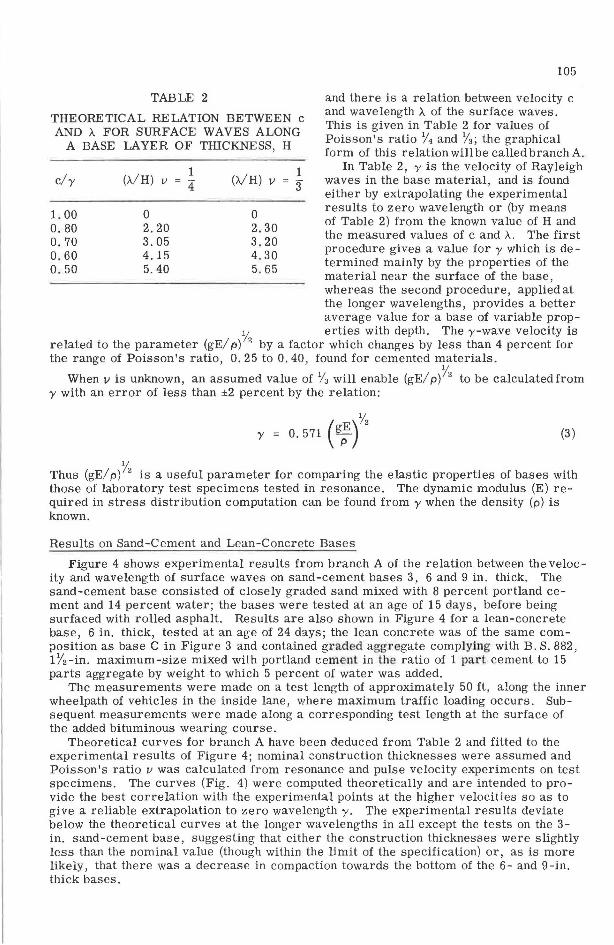
TABLE 2
THEORETICAL RELATION BETWEEN c AND A FOR SURF ACE WAVES ALONG
A BASE LAYER OF THICKNESS, H
c/y
1. 00 0.80 0.70 0.60 0.50
(A/H) 1
v - -- 4
0 2.20 3.05 4.15 5.40
1 (A/H) v = 3
0 2. 30 3.20 4. 30 5. 65
105
and there is a relation between velocity c and wavelength A of the surface waves. This is given in Table 2 for values of Poisson's ratio Y1 and Y3; the graphical form of this relation will be called branch A.
In Table 2, y is the velocity of Rayleigh waves in the base material, and is found either by extrapolating the experimental results to zero wavelength or (by means of Table 2) from the known value of H and the measured values of c and A. The first procedure gives a value for y which is de -termined mainly by the properties of the material near the surface of the base, whereas the second procedure, applied at the longer wavelengths, provides a better average value for a base of variable prop-
Y erties with depth. The y-wave velocity is related to the parameter (gE/ p) 2 by a factor which changes by less than 4 percent for the range of Poisson's ratio, 0. 25 to 0. 40, found for cemented materials.
When 11 is unknown, an assumed value of YJ will enable (gE/ p)Y2 to be calculated from y with an error of less than ±2 percent by the relation:
( E)Y2 y = 0. 571 gp (3)
Thus (gE/ p)Y2 is a useful parameter for comparing the elastic properties of bases with those of laboratory test specimens tested in resonance. The dynamic modulus (E) required in stress distribution computation can be found from y when the density (p) is known.
Results on Sand-Cement and Lean-Concrete Bases
Figure 4 shows experimental results from branch A of the relation between the velocity and wavelength of surface waves on sand-cement bases 3, 6 and 9 in. thick. The sand-cement base consisted of closely graded sand mixed with 8 percent portland cement and 14 percent water; the bases were tested at an age of 15 days, before being surfaced with rolled asphalt. Results are also shown in Figure 4 for a lean-concrete base, 6 in. thick, tested at an age of 24 days; the lean concrete was of the same composition as base C in Figure 3 and contained gnded aggregate complying with B. S. 882, 17'2-in. maximum-size mixed with portland cement in the ratio of 1 part cement to 15 parts aggregate by weight to which 5 percent of water was added.
The measurements were made on a test length of approximately 50 ft, along the inner wheelpath of vehicles in the inside lane, where maximum traffic loading occurs. Subsequent measurements were made along a corresponding test length at the surface of the added bituminous wearing course.
Theoretical curves for branch A have been deduced from Table 2 and fitted to the experimental results of Figure 4; nominal construction thicknesses were assumed and Poisson's ratio v was calculated from resonance and pulse velocity experiments on test specimens. The curves (Fig. 4) were computed theoretically and are intended to provide the best correlation with the experimental points at the higher velocities so as to give a reliable extrapolation to zero wavelength y. The experimental results deviate below the theoretical curves at the longer wavelengths in all except the tests on the 3-in. sand-cement base, suggesting that either the construction thicknesses were slightly less than the nominal value (though within the limit of the specification) or, as is more likely, that there was a decrease in compaction towards the bottom of the 6- and 9-in. thick bases.

106
6000
u 5 000 -4J
"' T </)
w > <{
;: 4 000
w u ~ 0:: ::::J </)
LL 0 >- 3000 .... u g Lil >
2000
• Sand cement H = 9in, 'If = 2750 ~sec, v =ls
o Sand cement H = 6 if\ 'IS= 2600 tt/sec, v =.1:1
.& Sand c ment H = 3in,lS= 2600 itlsec, v .~
t. Lean concrete H = 6in, 'IS= 6250 ttlsec,
"= ~
(II• Esf1mated Rayleigh wave ve1oc·1ty) v= Po·1ssons ratio
1000 '--~~~~~-'-~~~~~-L.~~~~~-L~__;=--~-=---'
0 2 WAVELENGTH - ft
3 4
Figure 4. Experimental results obtained from surface wave propagation on cemented bases of different nominal thicknesses (H).
Estimates of (gE/ p)% obtained from 'Y are compared in Table 3 with the corresponding parameter deduced from laboratory experiments on test specimens at an age of 28
days and cores drilled from the bases. The estimated value of (gE/ p)1/2 at 28 days on the bases was 6 to 20 percent below the same parameter measured on test specimens for both the sand-cement and lean concrete. This is not unusual because it is rarely
TABLE 3
COMPARISON OF RESULTS OBTAINED ON BASES AND TEST SPECIMENS
(gE/p)y' Estimated 'l'est ::ipec1mens
Type and Thickness Age 'Y E (gE/ p)y'
at 28 Days Cores at y of Base (days) (ft/ sec) (x 106 psi)
(ft/ sec) (gE/p)' 28 Days (ft/ sec)
(ft/ sec)
Sand-cement (3 and 6 in.) 15 2, 600 0.50 4,550 4, 950 5, 500 5, 200 Sand-cement (9 in . ) 15 2, 750 0.50 4,800 5.200 5,300 Lean concrete (6 in. ) 24 6,250 3. 5 10 750 10.900 13 ' 200
107
possible to produce such good compaction in the bases as in the test specimens. The
cores taken from the soil-cement bases gave a slightly higher value of (gE/ p)% than was derived from in situ measurements on the bases, but the discrepancy would have arisen because the cores were not from the full depth of the bases and probably represented the stronger material in the base.
TESTS ON ROADS HAVING CEMENTED BASES
Experimental Procedure
The experimental procedure is essentially the same as that described previously except that the experiments are made at the surface of the road. The relation between velocity and wavelength corresponding to branch A is modified by the presence of the extra surface layer which usually has a Young's modulus of elasticity comparable with
6000
500 ~ 9
<)
2: 400 -+'
I
>,__
8 --' w > 3000 w > ~ w
~ Q'. ::::> Ill 2000
1000
~ I • ~ I
~ I \ I ~ I \ I
• 0
c ol
October, 1957 May, 1960
-"'<l--o... 0------o --0--7
D
2 3 4 5 6 7 8 9 10 11 12 13 14 15 16 17
WAVELENGTH - ft
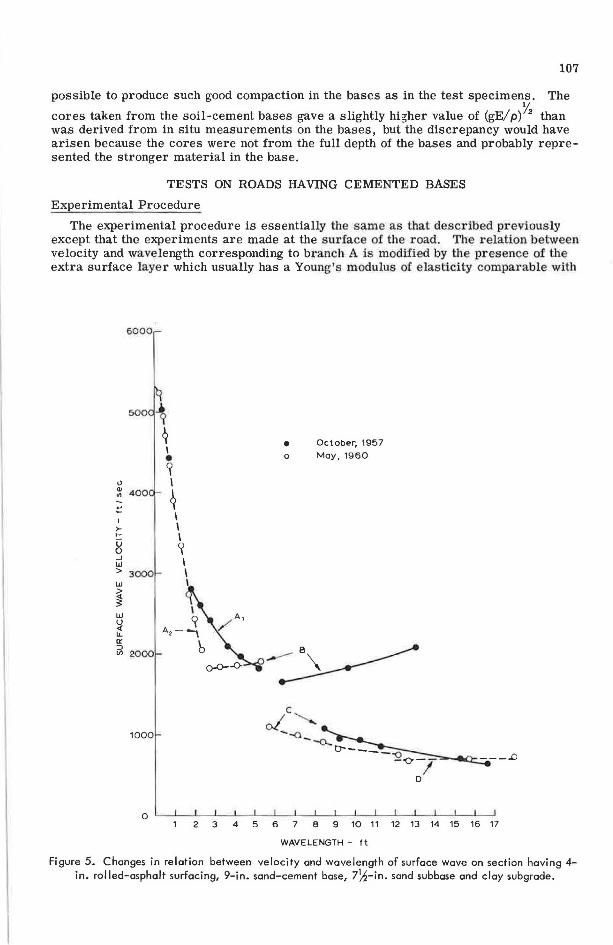
Figure 5. Changes in relation between velocity and wavelength of surface wave on section having 4-in. rot led-asphalt surfacing, 9-in. sand-cement base, 7~-in. sand subbase and clay subgrade.

108
the cemented base. In such cases, the relation corresponding to branch A can be constructed by adding the wavelengths from branch A of the separate layers at each velocity (~). This procedure provides a reliable approximation at velocities below the ywave velocity in Ule layer wiU1 the lowest modulus of elasticity and for ratios of moduli of less than 2:1. Lower velocity branches of the relation between velocity and wavelength become important during the breakup of cemented bases, and these are discussed later.
Results
The experimental results for flexural waves in a composite layer formed by a 4-in. rolled-asphalt surfacing and the 9-in. thick sand-cement layer , are shown in Figure 5 as branch A1· these results were obtained in 1957, immediately after the road was constructed before it was opened to traffic . In 1960 the experimental results fell on curve Az which represents propagation In the asphalt surfacing only and indicated thal the sand-cement base was no longer a continuous material.
Branch B (Fig. 5) can be explained by the compressional wave velocity in the clay subgrade bei ng higher than the compressional wave velocity in the sand subbase (4). The lheory indicates that branch B approaches the velocity of compressional waves in the sand subbase at short wavelengths, and the increase in velocities along branch B between 1957 and 1960 reflects the compaction that occurred in the subbase under traffic (3).
Branch C (Fig. 5) depends on the overall stiffness of the road. The value of the parameter c2.A for this branch is a useful indication of the stiffness of the road and approximately related to the inverse of the deflection of the surface in deflection beam experiments (3). The parameter c2.A decreased from about 90 units in 1957 to about 70 in 1960 showing that the decrease in stiffness due to breakup of the base more than offsets the incr ase in stiffness of the s ubbase .
Branch D is connected with the shear elastic properties of the broken base laye r (3) and gave a value for the dynamic Young's modulus of approximately 4 x 101 psi in 1960 compared wilh the original value of 6 105 psi in sound material.
There were even more spectacular changes in the relation between velocity and wavelength of s urface waves associated wtlh U1e breakup of the 6-in. lean-concrete base discussed previously. This base was on a sand subbase and clay subgrade but was surfaced with 4-in. bitumen macadam. Branch A (Fig. 6) represents flexural waves in the composite layer of surfacing plus base obtained in 1957 before the road was opened to traffic. Eighteen months later , there was no contribution to branch A from the base layer and branch A2 r efers solely lo vibrations in the bitumen macadam . Complete results for all experimentally observed branches of the relation between velocity and wavelength of surface waves in 1957 and 1960 were compared (Fig. 6). Corrections have b en applied to the results obtained in 1960 to allow or the effect of a different test temperature on the elastic properties of the bitumen-macadam layer.
Branch B gives the increase in compressional wave velocity in the sand subbase associated with the compaction occurring betweeu 1957 and 1960. In spite of the increased stiffness of the subbase, the overall stiffness has decreased considerably between 1957 and 1960 and c2 X for branch C fell from about 140 units to 60 units.
Branch D gives an approximate value for the shear wave velocity in the disintegrated lean concrete of 760 ft/sec . The effective dynamic Young's modulus of elasticity was about 6 x 10⁴ psi compared with the original value of 3. 5 x 10⁶ psi. The final value in 1960 was equivalent to that which has been obtained on well-compacted crushed-stone bases (3).
Braiich E gives a shear wave velocity of 610 ft/sec in the compacted sand subbase. The effective dynamic Young's modulus was 28, 000 psi compared with 9, 000 psi mea-sured directly on the subbase (3). he sand in the subbase was of the same type as was used in the sand-cement subbase and the results suggest that, in its compacted state, it attained an elastic modulus (28 000 psi) comparable with the badly broken sandcement base (40, 000 psi).

5000
., "' I
"' I ' .... ::::
~ I >- I >-- b u I g 3000 w > w
~ ~
w u i1_ 2000 0:: -:J (/)
1000
I
~/2 .., I 0 \
~ ...
"-......... c~ "'0.-
• 1957
... 1959
0 1960
,~ D o---o- --o----.,4
5 10 WAVELENGTH- It
-o- - - 7 - --0- - -
Ea
15
109
Figure 6. Change in relation between surface wave velocity and wavelength on a road having 4-in. bitumen-macadam surfacing, 6-in. lean-concrete base, 9-in. sand s®base on clay subgrade.
Discussion
The foregoing technique can be used to provide information on tensile stresses developed in cemented road bases and caused by the passage of traffic. It permits an estimate to be made as to whether the base will develop cracks from these stresses.
Figure 7 shows the computed tensile stresses at the bottom of two thicknesses of bases, 6 and 9 in., where Young's modulus of elasticity varied between 0. 5 to 6. 0 x 106 psi. The foundation material had a Young's modulus of 3 x 10⁴ psi (CBR about 17 percent). The cemented bases were each covered by a rolled-asphalt surfacing, 4-in. thick, having a Young's modulus of 105 psi; the asphalt has this modulus when the surface temperature is about 3 5 C. The wheel load for this calculation was 14, 000 lb. These conditions represent the passage of a very heavy wheel load at normal traffic speeds and correspond to a heavier load than the maximum legal loading for British roads. The mean r·elation between the Young's modulus and flexural strength of cemented and lean-concrete bases (Fig. 4) is also reproduced in Figure 7.
Only materials hav~ng a flexural strength of over 300 psi for a 6-in. base, or over 150 psi for a 9-in. base, would be likely to survive even a single traverse of a 14, 000-lb wheel load in this construction without cracking (Fig. 7). The flexural strength

110
6·0
5-0
4·0
.. 3 ·0 c::
IJ 2·0 0
0
/ /
I I ,
100
I I
I
I I
I I
I
.,,. .... .... ,,.,.
I I 1 9-in base I I
·':I CJJ/
/
I
I ·~/
(0 I
" I ~I
I I
I
6-in bas<>
I
I , Hz= 6in or9in Cemented base E2 =0 ·5-6·0x 10'° lb/in 2
/ / ,
,../ ' 1T777TlT7 Sand /clay E 3 = 3 x 10 .. lb / in'Z
~"'
200 300 400 500 - -----tensile stress -lb/in• --- flexural strength
Figure 7. Computed tensile stresses at bottom surfaces of6-and9-in.cemented basesof different moduli of elasticity compared with flexural strength.
measured on beams is, however, no guide to the behavior of the actual bases , and it is likely to give a very conservative estimate of the resistance of the base to flexural failure for the following reasons.
1. Additional stresses from causes other than traffic are likely to be present, i.e., those due to temperature or moisture gradient.
2. The fatigue strength is lower than the flexural strength derived from a single loading.
3. Cemented materials obey the "weak link" theory and failure will occur at lower stresses in the larger volume of the base than in relatively small test specimens.
At present, deficiencies in our knowledge of the physical properties of these types of material, and particularly of their fatigue failure under appropriate stress conditions, make it impossible to make reliable use of the calculations of stresses and displacements for design purposes. A very approximate idea of the overestimation of the failure condition by the flexural strength may be obtained by comparing the results of Figure 7 with the road performance of lean-concrete bases in comparable road structures. After 5 years of mixed traffic containing between 2 and 3 percent vehicles with half-axle loads (i.e., wheel or wheel units) between 10, 000 and 20, 000 lb, tests on the leanconcrete bases indicated appreciable cracking of the 6-in. base and intermittent cracking of the 9-in. base. This suggests that the flexural strength measured on beams is perhaps 2 or 3 times the failure strength of the in situ material. Once a crack forms in the base there is stress relief in the adjacent material and the frequency of occurrence of cracks depends on the redistribution of stress in relation to the failure strength of the material (6). The stronger the material, the greater is the distance between cracks, hut in the absence of reinforcement there is also a tendency for the cracks to widen giving poor transference of shear stresses and producing reflection cracks in the surfacing.
For the weaker cemented materials, it has been suggested (6) that the material breaks down under traffic into small interlocking pieces, the size of hard core, separated by fine cracks, and thus behaves in a similar manner to a flexible base. The present work shows that the weaker cemented materials break down to give a material having an elastic modulus comparable to that of the original unbound compacted material.

111
ACKNOWLEDGMENT
The work described was carried out as part of the program of the Road Research Board of the Department of Scientific and Industrial Research. The article is published by permission of the Director of Road Research.
REFERENCES
1. Whiffin, A. C., and Lister N. W. The Application of Elastic Theory of Flexible Pavements. Proc. Internat. Conf. on Asphalt Pavements, Univ. of Michigan, Aug. 20-24, 1962, Ann Arbor, pp. 499-521, 1963.
2. Jones, R. Non-Destructive Testing of Concrete. Cambridge Engineering Series, Cambridge, England, Cambridge Univ. Press, 1962.
3. Jones, R. Following Changes in the Properties of Road Bases and Subbases by the Surface Wave Propagation Method. Civ. Eng., London, Vol. 58, No. 682, 613, 615, 617; No. 683, 777-80, 1963.
4. Jones, R. Surface Wave Technique for Measuring the Elastic Properties and Thickness of Roads: Theoretical Development. Brit. Jour. Appl. Phys., Vol. 13, No. 1, pp. 21-29, 1962.
5. Jones, R. In-Situ Measurement of the Dynamic Properties of Soil by Vibration Methods. Geotechnique, London, Vol. 8, No. 1, pp. 1-21, 1958.
6. Maclean, D. J., and Robinson, P. J. M. Methods of Soil Stabilization and Their Application to the Construction of Airfield Pavements. Proc. Inst. Civ. Engineers, Pt. II, Vol. 2, No. 2, pp. 447-486, 1953.