Embed Size (px)
Citation preview

Measurement of partial discharges in medium voltage cable lines 105
MEASUREMENT OF PARTIAL DISCHARGES IN MEDIUM VOLTAGE CABLE LINES
Sławomir Noske / ENERGA-OPERATOR S.A. Elbląg Branch
PARTIAL DISCHARGES A partial discharge is limited in space to an electrical discharge that partially bridges an insulator. It is
caused by a localised concentration of voltage within an insulator or on its surface. When the local electric field exceeds the value of inception voltage, a first seed electron starts an electron avalanche. Fig. 1 shows an equivalent circuit with a void where a partial discharge occurs. Partial discharges vary, depending on a number of factors which include the type of insulation as well as the location and geometry of the voids.
Cb
Cc
Fig. 1. Equivalent circuit diagram of cable line with a void in the insulation where capacities Cc, Cb represent insulation located serial and parallel to the void.
The probability of discharges occurring may, among other things, depend on the type insulation. Partial discharges may result from the insulation’s deteriorating state. Likewise, the degradation of insulation quality may result from the partial discharges, i.e. insulation material degradation and partial discharges mutually af-fect one another. On account of the fact that partial discharges occur in association with the deteriorating state of the insulation, they are harmful and through repeated occurrences frequently lead to power failure. They damage insulation when, for example, high energy electrons break chemical bonds in the polymers or through the aggressive effects of chemical decay resulting from the break up of molecules.
Medium voltage cable lines are an important element of electricity distribution company property. They are used to supply electricity to highly urbanised areas, where users are particularly sensitive to power failures and the conse-quences are very expensive to remedy. The management of such networks has so far chiefly relied on the analysis of failure frequency. Increasing failure frequency has been regarded as the deciding factor in assessing a given power cable line’s technical condition.
Now developments in measuring apparatus allow for new ways of examining the exploitation of power net-works, providing a greater understanding of their technical state. Thanks to the new information, it is now possible to improve the operation and management of cable networks. One can now examine the technical condition of the insula-
tion of various elements within a power cable line. One of these modern methods involves the measurement of partial discharges.
Abstract

MEASUREMENT OF PARTIAL DISCHARGES Partial discharges were recognised as harmful to insulation already at the start of the 20th century, when
high voltage devices started being used. The first industrial tests of partial discharges were carried out in 1940. Developments in technology and computer science in the last decades of the 20th century allowed for the
construction of devices able to measure partial discharges in active power distribution networks.One of the solutions allowing for the measurement of partial discharges (PD) in medium voltage cables
is the Seba KMT OWTS-25 system. OWTS is currently used by the Elbląg branch of ENERGA-OPERATOR S.A.
Photo. 1. Cable test van using the OWTS-25 system
This system uses as the test voltage a self-extinguishing voltage wave. It is produced by raising the tested cable voltage to a required level and then discharging it through an air-core coil. The voltage frequency de-pends on the cable’s capacitance and the coil’s inductance. In tested cables this frequency is generally within the range of 200–800 Hz. Suppression of the voltage amplitude is associated with dielectric losses in the tested cable.
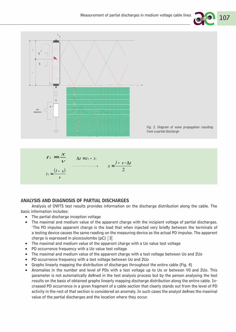
OWTS measures the voltage wave from the load induced during the partial discharge. It spreads in two opposite directions. The device first measures the wave heading for the cable end connected to it (the voltage wave proportional to the load value produced during the PD) and next the other wave after it has rebounded from the other end of the cable. Measurement of the time difference between the two waves allows us to locate exactly where the partial discharge occurred (Fig. 3). Pre-test calibration allows the device to measure PD load intensity in picoCoulombs (pC). This calibration is conducted in accordance with norm IEC 60270.
106Rozwój informatyczny i technologiczny w ostatnich dekadach XX wieku pozwolił na budowę
przewoźnych urządzeń dających możliwość pomiaru wyładowań niezupełnych w eksploatowanych
sieciach energetycznych.
Jednym z rozwiązań pozwalających mierzyć wyładowania niezupełne (wnz) w liniach kablowych
średniego napięcia jest system pomiarowy OWTS-25 firmy SEBA KMT. OWTS jest obecnie
wykorzystywany przez ENERGA-OPERATOR SA Oddział w Elblągu.
Rys. 2. Wóz pomiarowy z zainstalowanym systemem OWTS-25
System ten wykorzystuje jako napięcie probiercze samogasnacą falę napięciową. Wytwarzana
jest ona poprzez ładowanie badanego kabla do pożądanego napięcia, a następnie rozładowanie go
przez specjalnie zaprojektowaną cewkę bezrdzeniową. Częstotliwość napięcia zależna jest od
pojemności kabla i indukcyjności cewki. W praktyce, dla badanych linii kablowych mieści się
ona w granicach 200–800 Hz. Tłumienie zanikającej amplitudy napięcia związane jest ze
stratami dielektrycznymi w badanym kablu.
LCf
π2
1
OWTS mierzy falę napięciową powstałą od ładunku indukowanego podczas wyładowania
niezupełnego. Fala napięciowa rozchodzi się w dwóch kierunkach. Aparatura mierzy falę biegnącą w
kierunku końca z podłączoną aparaturą (fala napięciowa proporcjonalna do wartości ładunku
powstałego podczas wnz), a następnie falę odbitą od drugiego końca kabla. Pomiar różnicy czasu
między pomierzonymi falami pozwala określić miejsce wystąpienia wyładowania niezupełnego (rys.
3). Dokonana przed pomiarem kalibracja pozwala na wyskalowanie aparatury i pomiar
Sławomir Noske / ENERGA-OPERATOR S.A. Elbląg Branch
t
Detekcja wnz
lq
/2q
/2
l -x
x
l
ANALYSIS AND DIAGNOSIS OF PARTIAL DISCHARGES Analysis of OWTS test results provides information on the discharge distribution along the cable. The
basic information includes: • The partial discharge inception voltage • The maximal and medium value of the apparent charge with the incipient voltage of partial discharges.
‘The PD impulse apparent charge is the load that when injected very briefly between the terminals of a testing device causes the same reading on the measuring device as the actual PD impulse. The apparent charge is expressed in picocoulombs (pC) [3]
• The maximal and medium value of the apparent charge with a Uo value test voltage • PD occurrence frequency with a Uo value test voltage • The maximal and medium value of the apparent charge with a test voltage between Uo and 2Uo• PD occurrence frequency with a test voltage between Uo and 2Uo • Graphs linearly mapping the distribution of discharges throughout the entire cable (Fig. 4)• Anomalies in the number and level of PDs with a test voltage up to Uo or between V0 and 2Uo. This
parameter is not automatically defined in the test analysis process but by the person analysing the test results on the basis of obtained graphs linearly mapping discharge distribution along the entire cable. In-creased PD occurrence in a given fragment of a cable section that clearly stands out from the level of PD activity in the rest of that section is considered an anomaly. In such cases the analyst defines the maximal value of the partial discharges and the location where they occur.
107Measurement of partial discharges in medium voltage cable lines
intensywności wyładowania wnz w pikokulombach (pC). Kalibracja dokonywana jest zgodnie z PN-
EN 60270 (tłumaczenie międzynarodowej normy IEC 60270).
t
Detekcja
wnz
l
q/2
q/2
l -x
x
l
Rys. 3. Schematyczny obraz rozchodzenia się fali powstałej w wyniku wyładowania
niezupełnego
2
tvlx
Δ
v
xlt
2
12 ttt Δv
xt 1
Analiza i diagnoza wyładowań niezupełnych
Analiza wyników pomiaru dokonanych systemem OWTS dostarcza informacji o rozkładzie
wyładowań w funkcji długości kabla. Do podstawowych informacji uzyskanych z analizy
należą:
Napięcie początkowe wyładowań niezupełnych
Wartość średnia i maksymalna ładunku pozornego przy napięciu początkowym
wyładowań niezupełnych. „Ładunek pozorny impulsu wnz odpowiada ładunkowi,
który wstrzyknięty w bardzo krótkim czasie między zaciski obiektu badanego
Fig. 2. Diagram of wave propagation resulting from a partial discharge
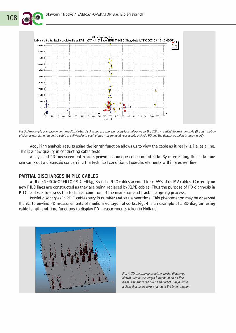
Fig. 3. An example of measurement results. Partial discharges are approximately located between the 210th m and 230th m of the cable (the distribution of discharges along the entire cable are divided into each phase – every point represents a single PD and the discharge value is given in pC).
Acquiring analysis results using the length function allows us to view the cable as it really is, i.e. as a line. This is a new quality in conducting cable tests
Analysis of PD measurement results provides a unique collection of data. By interpreting this data, one can carry out a diagnosis concerning the technical condition of specific elements within a power line.
PARTIAL DISCHARGES IN PILC CABLESAt the ENERGA-OPERTOR S.A. Elbląg Branch PILC cables account for c. 65% of its MV cables. Currently no
new PILC lines are constructed as they are being replaced by XLPE cables. Thus the purpose of PD diagnosis in PILC cables is to assess the technical condition of the insulation and track the ageing process.
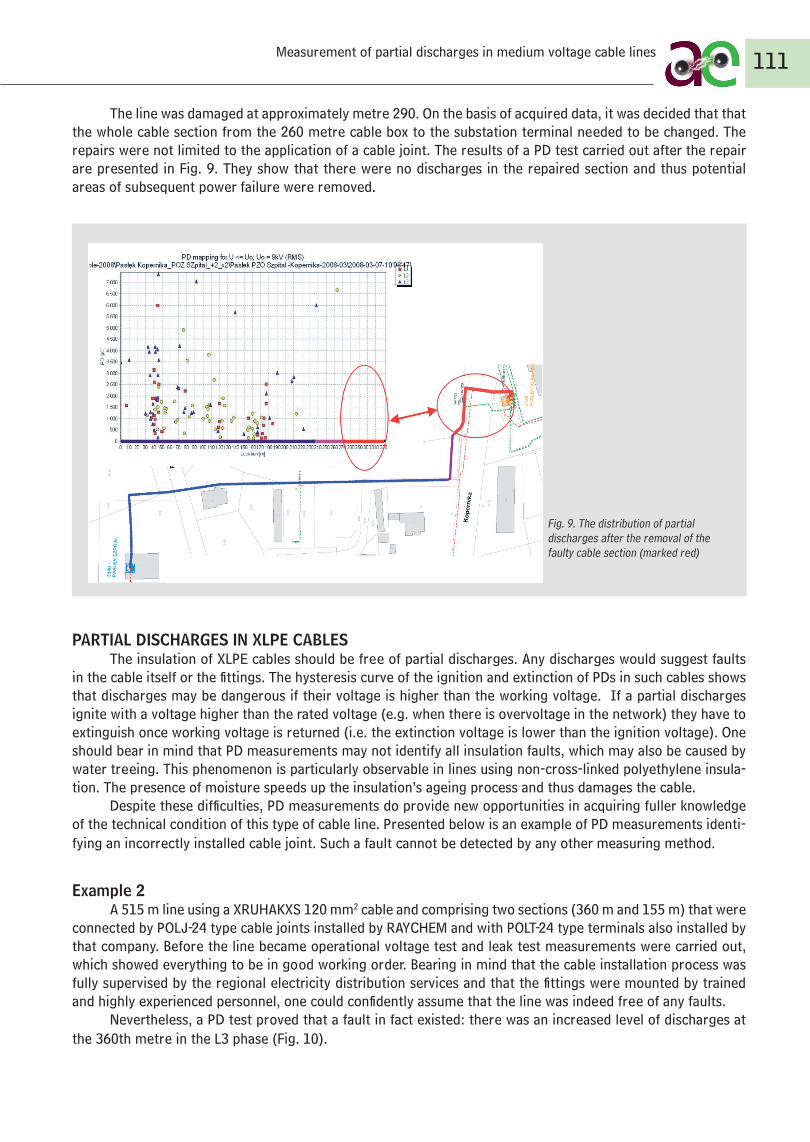
Partial discharges in PILC cables vary in number and value over time. This phenomenon may be observed thanks to on-line PD measurements of medium voltage networks. Fig. 4 is an example of a 3D diagram using cable length and time functions to display PD measurements taken in Holland.
108
Fig. 4. 3D diagram presenting partial discharge distribution in the length function of an on-line measurement taken over a period of 8 days (with a clear discharge level change in the time function)
Sławomir Noske / ENERGA-OPERATOR S.A. Elbląg Branch

Fig. 5. Change in the level of partial discharges depending on the load level in the cable
Figure 5 shows the dependence between the load in the cable and the value of partial discharges. The PD level rises when the load (pressure and temperature in the cable) falls.
When diagnosing the technical condition of PILC lines on the basis of partial discharge measurements, one needs to take into account that:
• Partial discharges may occur in the cable insulation, but their appearance is most usually of a dispersed nature
• The level of discharges and their intensity varies in time and is dependent on the level to which the cable is loaded. This considerably hinders tracing changes associated with the deteriorating state of insulation.
• Practical experience has shown that the level of discharges is dependent on the quality of the cable. In the past a country’s economic condition was undoubtedly a factor determining the quality of cables. There-fore older cables are not always characterised by a higher level of PDs (the ageing structure of a PILC cable line is shown in Fig. 6). The example of a line comprising two cable sections from different years (with different PD levels and intensities) is presented in Fig. 7.
0,00
2,00
4,00
6,00
8,00
10,00
12,00
14,00
16,00
18,00
20,00
1952
1960
1963
1966
1969
1972
1975
1978
1981
1984
1987
1990
1993
1996
1999
2002
2005
2008
l [km
]
długość kabli PILC
Fig. 6 The length of PILC cables installed in the MV network in specific years by ENERGA-Operator SA Elbląg Branch.
109Measurement of partial discharges in medium voltage cable lines
0,00
2,00
4,00
6,00
8,00
10,00
12,00
14,00
16,00
18,00
20,00
1952
1958
1961
1963
1965
1967
1969
1971
1973
1975
1977
1979
1981
1983
1985
1987
1989
1991
1993
1995
1997
1999
2001
2003
2005
2007
2009
[km
]

The above mentioned phenomena mean that diagnosing the state of insulation in these cables is difficult and requires a lot of experience. The current state of research has not yet allowed us to determine a standard PD level beyond which the operator should decide to change an entire section in a cable network. In assessing the technical condition of cables one should pay particular attention to anomalies. In this case anomalies are places where there is an increased level of PDs.
Despite the lack of hard and fast rules to determine the assessment of PILC insulation, there are methods of facilitating decisions concerning operation. Below is an example of a cable line whose section, on the basis of PD tests carried out after a power failure, is changed. In this case it was decided that in order to prevent further power failures the application of a cable repair joint would be inadequate.
Example 1Fig 8 shows cable line HAKnFtA 3x120 mm2, its route map and the results of its PD analysis. With a V0 volt-
age, two places on the cable appear to have increased PD levels (30–50 m and 280–300 m).
110Sławomir Noske / ENERGA-OPERATOR S.A. Elbląg Branch
Fig. 8. The distribution of partial discharges on the examined cable line before the power failure.
Fig. 7. Cable line comprising two cable sections (A – HAKnFtA 3x120 mm2, built in 1979; B – HAKnFtA 3x120 mm2, built in 1984). Section A – breakdown voltage below V0, discharge values up to 8,000 pC, voltage up to 1.7V0 only with individual discharges of c. 25,000 pC. Section B – no discharges with V0 voltage, the discharge level exceeds 100,000 pC with test voltage values up to 1.7V0.
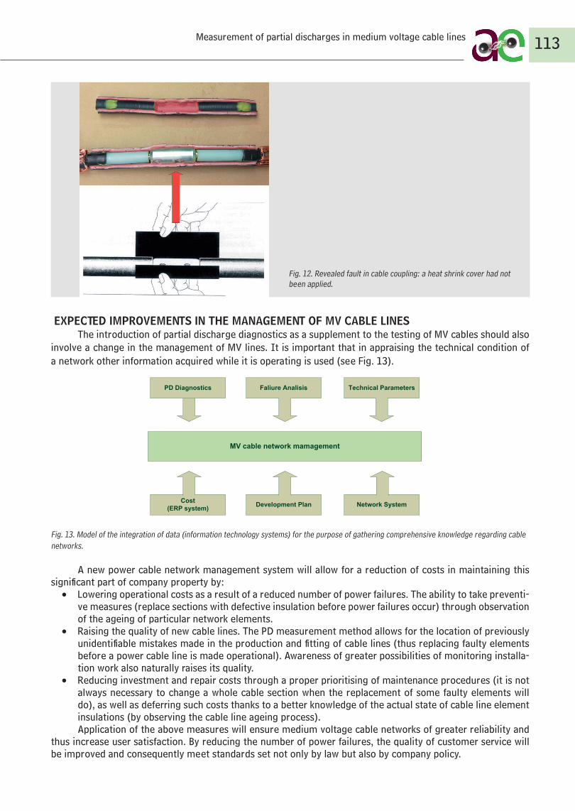
The line was damaged at approximately metre 290. On the basis of acquired data, it was decided that that the whole cable section from the 260 metre cable box to the substation terminal needed to be changed. The repairs were not limited to the application of a cable joint. The results of a PD test carried out after the repair are presented in Fig. 9. They show that there were no discharges in the repaired section and thus potential areas of subsequent power failure were removed.
PARTIAL DISCHARGES IN XLPE CABLESThe insulation of XLPE cables should be free of partial discharges. Any discharges would suggest faults
in the cable itself or the fittings. The hysteresis curve of the ignition and extinction of PDs in such cables shows that discharges may be dangerous if their voltage is higher than the working voltage. If a partial discharges ignite with a voltage higher than the rated voltage (e.g. when there is overvoltage in the network) they have to extinguish once working voltage is returned (i.e. the extinction voltage is lower than the ignition voltage). One should bear in mind that PD measurements may not identify all insulation faults, which may also be caused by water treeing. This phenomenon is particularly observable in lines using non-cross-linked polyethylene insula-tion. The presence of moisture speeds up the insulation’s ageing process and thus damages the cable.
Despite these difficulties, PD measurements do provide new opportunities in acquiring fuller knowledge of the technical condition of this type of cable line. Presented below is an example of PD measurements identi-fying an incorrectly installed cable joint. Such a fault cannot be detected by any other measuring method.
Example 2A 515 m line using a XRUHAKXS 120 mm2 cable and comprising two sections (360 m and 155 m) that were
connected by POLJ-24 type cable joints installed by RAYCHEM and with POLT-24 type terminals also installed by that company. Before the line became operational voltage test and leak test measurements were carried out, which showed everything to be in good working order. Bearing in mind that the cable installation process was fully supervised by the regional electricity distribution services and that the fittings were mounted by trained and highly experienced personnel, one could confidently assume that the line was indeed free of any faults.
Nevertheless, a PD test proved that a fault in fact existed: there was an increased level of discharges at the 360th metre in the L3 phase (Fig. 10).
111
Fig. 9. The distribution of partial discharges after the removal of the faulty cable section (marked red)
Measurement of partial discharges in medium voltage cable lines

Partial discharges occurred in a place where two cable sections were joined. This indicated a joint fault in the L3 phase. Partial discharges occur with V0 voltage and this causes the danger of power failure. On the basis of explanations provided by the manufacturers of the cable joint the most probable reason for the fault was es-tablished: the fitters had failed to apply a heat shrink cover on one of the connectors. The line was built in 2005 and for three years it was subjected to regular tests which revealed no changes (rise) in the level of discharges; the line appeared to be undamaged. In this case one may assume that insulation degradation proceeded very slowly. In order to confirm the PD testing results, the faulty joint was cut out and examined in a Poznań Univer-sity of Technology laboratory, using James G. Biddle Co. equipment. The test findings verified those obtained from the OWTS equipment.
0
2000
4000
6000
8000
10000
12000
14000
16000
PD-Uośr PD-Uomax PD-2Uośr PD-2Uomax
2005-06-01
2005-09-26
2006-10-02
2007-01-25
2007-09-12
2008-02-12
In the laboratory registered discharges with a value of several score pC (whereas in situ measurements registered discharges with a value of several hundred pC). With such values the initial voltage turned out to be considerably lower than V0 (4 kV).
.
112
Fig. 11. Comparison of PD measurement test results, values given in pC
Photo. 2. Partial discharge image during tests carried out on the faulty cable joint using James G. Biddle Co. apparatus.
Sławomir Noske / ENERGA-OPERATOR S.A. Elbląg Branch
0
2000
4000
6000
8000
10000
12000
14000
16000
PD-Uo avg PD-Uo max PD-2Uo avg PD-2Uo max
2005-06-012005-09-262006-10-022007-01-252007-09-122008-02-12
Fig. 10. The distribution of partial discharges in the 360 m joint (L3 phase) with a test voltage value up to V0 and also up to 2Uo
EXPECTED IMPROVEMENTS IN THE MANAGEMENT OF MV CABLE LINES The introduction of partial discharge diagnostics as a supplement to the testing of MV cables should also
involve a change in the management of MV lines. It is important that in appraising the technical condition of a network other information acquired while it is operating is used (see Fig. 13).
Fig. 13. Model of the integration of data (information technology systems) for the purpose of gathering comprehensive knowledge regarding cable networks.
A new power cable network management system will allow for a reduction of costs in maintaining this significant part of company property by:
• Lowering operational costs as a result of a reduced number of power failures. The ability to take preventi-ve measures (replace sections with defective insulation before power failures occur) through observation of the ageing of particular network elements.
• Raising the quality of new cable lines. The PD measurement method allows for the location of previously unidentifiable mistakes made in the production and fitting of cable lines (thus replacing faulty elements before a power cable line is made operational). Awareness of greater possibilities of monitoring installa-tion work also naturally raises its quality.
• Reducing investment and repair costs through a proper prioritising of maintenance procedures (it is not always necessary to change a whole cable section when the replacement of some faulty elements will do), as well as deferring such costs thanks to a better knowledge of the actual state of cable line element insulations (by observing the cable line ageing process). Application of the above measures will ensure medium voltage cable networks of greater reliability and
thus increase user satisfaction. By reducing the number of power failures, the quality of customer service will be improved and consequently meet standards set not only by law but also by company policy.
113
Fig. 12. Revealed fault in cable coupling: a heat shrink cover had not been applied.
Measurement of partial discharges in medium voltage cable lines
Cost (ERP system) Development Plan Network System
MV cable network mamagement
Faliure Analisis Technical ParametersPD Diagnostics

LITERATURE
1. Gulski E., Diagnozowanie wyładowań niezupełnych w urządzeniach wysokiego napięcia w eksploatacji, Warszawa, Oficyna Wydawnicza Politechniki Warszawskiej, 2003.
2. Guide for partial discharge measurements in compliance to IEC 60270, CIGRE Working Group D1.33, 2008.3. Noske S., Efektywne zarządzanie siecią kablową SN, Elektro-info, 2009, nr 1–2.4. Noske S., Wykorzystanie diagnostyki opartej o pomiar wyładowań niezupełnych do zarządzania siecią kablową
średniego napięcia, Konferencyjne Infotech 2008. 5. PN-EN 60270, Wysokonapięciowa technika probiercza. Pomiar wyładowań niezupełnych, PKN, Warszawa 2003.6. Rakowska A., Kryteria oceny weryfikujące jakość polietylenu usieciowanego stosowanego jako izolacja kabli elek-
troenergetycznych, Poznań, Wydawnictwo Politechniki Poznańskiej, 2000.7. Rakowska A., Siodła K., Noske S., Wyniki badań wyładowań niezupełnych jako źródło informacji wspomagających
zarządzanie siecią kablową średnich napięć, Przegląd Elektrotechniczny, 2008, nr 10.8. Van der Wielen P., Steennis F.: First Field Experience of On-line Partial Discharge Monitoring of MV Cable Systems
with Location, 20th International Conference on Electricity Distribution, Prague 2009.9. Wester F., Condition Assessment of Power Cables using Partial Discharge Diagnosis at Damped AC Voltages, Optima
Grafische Communicatie, Rotterdam 2004.
114Sławomir Noske / ENERGA-OPERATOR S.A. Elbląg Branch


![[1].PhD Thesis Modelling of Cavity Partial Discharges](https://img.pdfslide.net/doc/110x75/54fdcdb94a7959422b8b492b/1phd-thesis-modelling-of-cavity-partial-discharges.jpg)