Embed Size (px)
Citation preview
International Journal of Science, Engineering and Technology Research (IJSETR), Volume 3, Issue 10, October 2014
2800
ISSN: 2278 – 7798 All Rights Reserved © 2014 IJSETR
Abstract —The surface of the earth is not smooth and flat. As a
consequence, there is a natural phenomenon that disrupts true
orthogonality of photo image feature. On an aerial photograph
the displacement of image due to variation in relief of the terrain
is known as relief displacement or height distortion. Relief
displacement can also be used to determine the height of an
object from a single vertical photograph if the amount of
displacement (d) can be accurately measured on the photograph.
Height determination is more accurate for tall features imaged
near the edge of the photograph. This is because relief
displacement at this location is more exaggerated and separation
between the top and the base of features is clearly visible on the
photograph, thus, the distance between the top and the base is
more precisely measured.
Index Terms—Aerial Photograph, Flying Height, Focal
Length, Relief Displacement, Remote Sensing
I. INTRODUCTION
Relief displacement is the radial distance between where an
object appears in an image to where it actually should be
according to a Planimetric coordinate system. The images of
ground positions are shifted or displaced due to terrain relief,
in the central projection of an aerial photograph. If a
photograph is truly vertical, the displacement of images is in
a direction radial from the photograph center. This
displacement is called the radial displacement due to relief.
Radial displacement due to relief is also responsible for scale
differences within any one photograph, and for this reason a
photograph is not an accurate map.
Relief displacement is caused by differences in relative
elevation of objects photographed. All objects that extend
above or below a datum plane have their photographic
images displaced to a greater or lesser extent. This
displacement occurs always along the line which connects
the photo point and the nadir and is, therefore termed “radial
line displacement”. Or this displacement is always radial
with respect to principal point. It increases with increasing
height of the feature and the distance from nadir.
II. RELIEF DISPLACEMENT
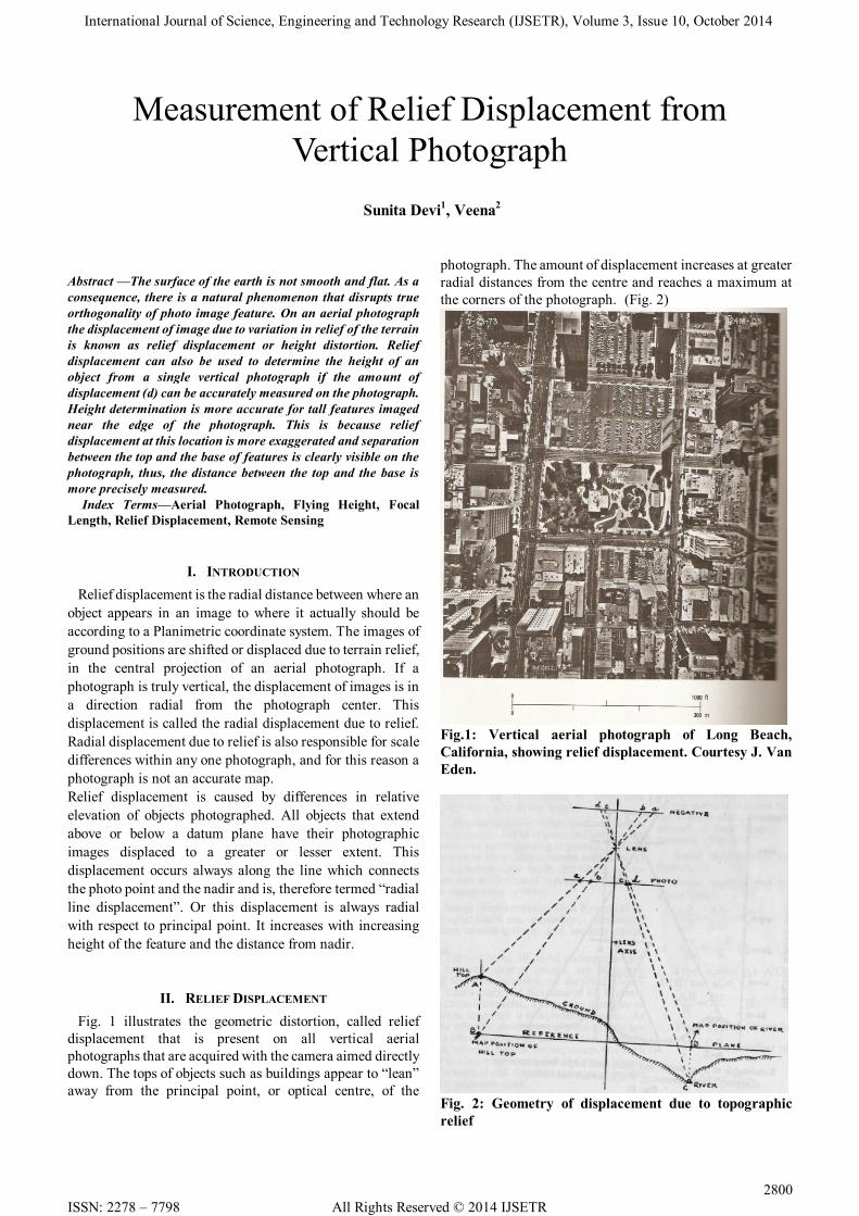
Fig. 1 illustrates the geometric distortion, called relief
displacement that is present on all vertical aerial
photographs that are acquired with the camera aimed directly
down. The tops of objects such as buildings appear to “lean”
away from the principal point, or optical centre, of the
photograph. The amount of displacement increases at greater
radial distances from the centre and reaches a maximum at
the corners of the photograph. (Fig. 2)
Fig.1: Vertical aerial photograph of Long Beach,
California, showing relief displacement. Courtesy J. Van
Eden.
Fig. 2: Geometry of displacement due to topographic
relief
Measurement of Relief Displacement from
Vertical Photograph
Sunita Devi1, Veena
2
International Journal of Science, Engineering and Technology Research (IJSETR), Volume 3, Issue 10, October 2014
ISSN: 2278 – 7798 All Rights Reserved © 2014 IJSETR 2801
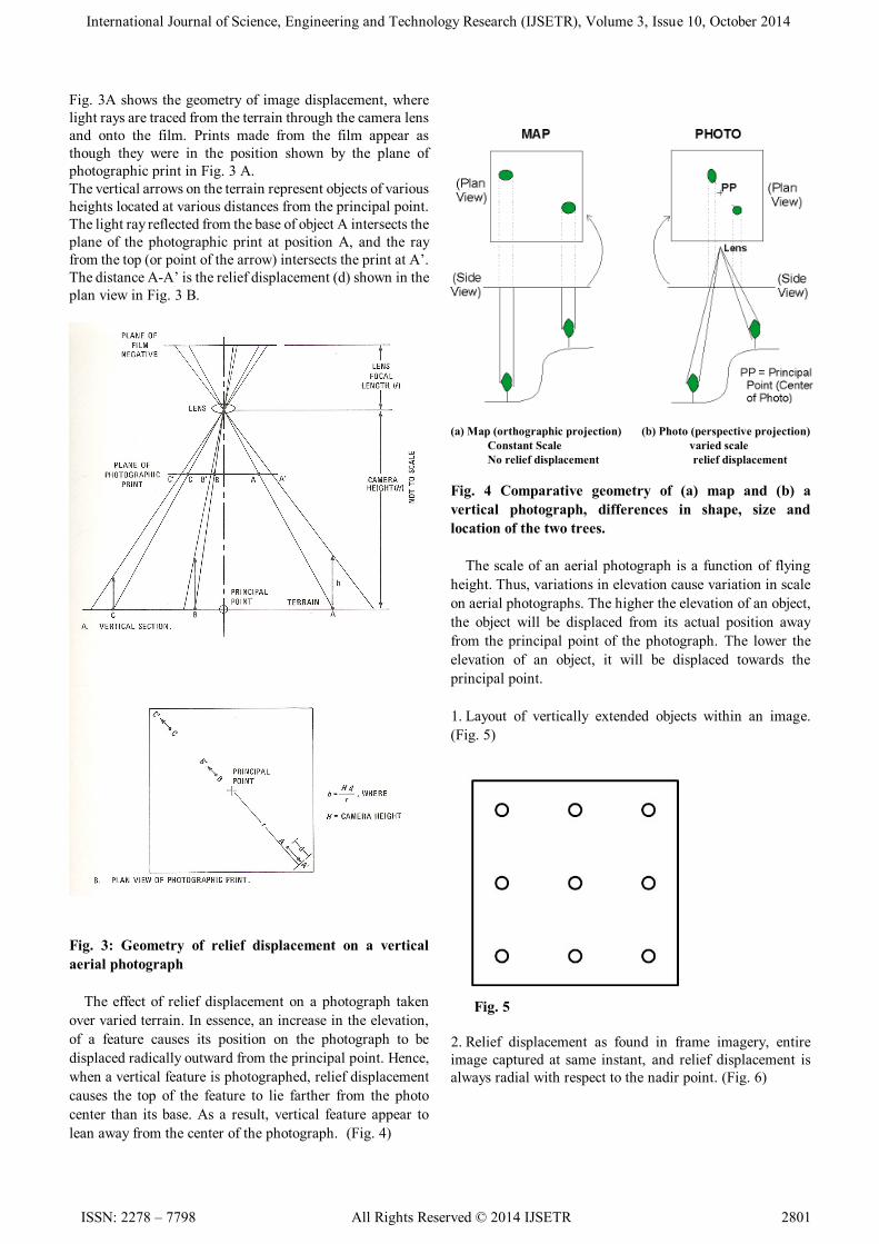
Fig. 3A shows the geometry of image displacement, where
light rays are traced from the terrain through the camera lens
and onto the film. Prints made from the film appear as
though they were in the position shown by the plane of
photographic print in Fig. 3 A.
The vertical arrows on the terrain represent objects of various
heights located at various distances from the principal point.
The light ray reflected from the base of object A intersects the
plane of the photographic print at position A, and the ray
from the top (or point of the arrow) intersects the print at A’.
The distance A-A’ is the relief displacement (d) shown in the
plan view in Fig. 3 B.
Fig. 3: Geometry of relief displacement on a vertical
aerial photograph
The effect of relief displacement on a photograph taken
over varied terrain. In essence, an increase in the elevation,
of a feature causes its position on the photograph to be
displaced radically outward from the principal point. Hence,
when a vertical feature is photographed, relief displacement
causes the top of the feature to lie farther from the photo
center than its base. As a result, vertical feature appear to
lean away from the center of the photograph. (Fig. 4)
(a) Map (orthographic projection) (b) Photo (perspective projection)
Constant Scale varied scale
No relief displacement relief displacement
Fig. 4 Comparative geometry of (a) map and (b) a
vertical photograph, differences in shape, size and
location of the two trees.
The scale of an aerial photograph is a function of flying
height. Thus, variations in elevation cause variation in scale
on aerial photographs. The higher the elevation of an object,
the object will be displaced from its actual position away
from the principal point of the photograph. The lower the
elevation of an object, it will be displaced towards the
principal point.
1. Layout of vertically extended objects within an image.
(Fig. 5)
Fig. 5
2. Relief displacement as found in frame imagery, entire
image captured at same instant, and relief displacement is
always radial with respect to the nadir point. (Fig. 6)
International Journal of Science, Engineering and Technology Research (IJSETR), Volume 3, Issue 10, October 2014
2802
ISSN: 2278 – 7798 All Rights Reserved © 2014 IJSETR
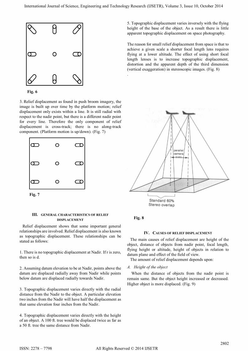
Fig. 6
3. Relief displacement as found in push broom imagery, the
image is built up over time by the platform motion; relief
displacement only exists within a line. It is still radial with
respect to the nadir point, but there is a different nadir point
for every line. Therefore the only component of relief
displacement is cross-track; there is no along-track
component. (Platform motion is up/down). (Fig. 7)
Fig. 7
III. GENERAL CHARACTERISTICS OF RELIEF
DISPLACEMENT
Relief displacement shows that some important general
relationships are involved. Relief displacement is also known
as topographic displacement. These relationships can be
stated as follows:
1. There is no topographic displacement at Nadir. If r is zero,
then so is d.
2. Assuming datum elevation to be at Nadir, points above the
datum are displaced radially away from Nadir while points
below datum are displaced radially towards Nadir.
3. Topographic displacement varies directly with the radial
distance from the Nadir to the object. A particular elevation
two inches from the Nadir will have half the displacement as
that same elevation four inches from the Nadir.
4. Topographic displacement varies directly with the height
of an object. A 100 ft. tree would be displaced twice as far as
a 50 ft. tree the same distance from Nadir.
5. Topographic displacement varies inversely with the flying
height of the base of the object. As a result there is little
apparent topographic displacement on space photography.
The reason for small relief displacement from space is that to
achieve a given scale a shorter focal length lens requires
flying at a lower altitude. The effect of using short focal
length lenses is to increase topographic displacement,
distortion and the apparent depth of the third dimension
(vertical exaggeration) in stereoscopic images. (Fig. 8)
.
Fig. 8
IV. CAUSES OF RELIEF DISPLACEMENT
The main causes of relief displacement are height of the
object, distance of objects from nadir point, focal length,
flying height or altitude, height of objects in relation to
datum plane and effect of the field of view.
The amount of relief displacement depends upon:
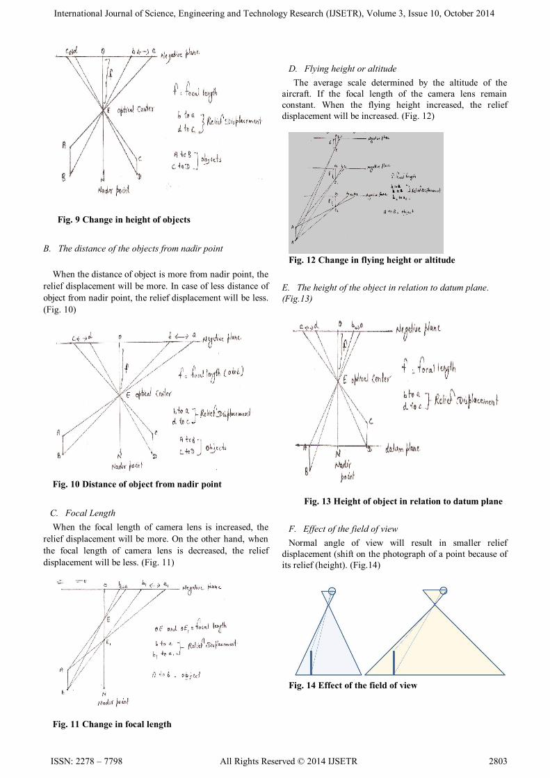
A. Height of the object
When the distance of objects from the nadir point is
remain same. But the object height increased or decreased.
Higher object is more displaced. (Fig. 9)
International Journal of Science, Engineering and Technology Research (IJSETR), Volume 3, Issue 10, October 2014
ISSN: 2278 – 7798 All Rights Reserved © 2014 IJSETR 2803
Fig. 9 Change in height of objects
B. The distance of the objects from nadir point
When the distance of object is more from nadir point, the
relief displacement will be more. In case of less distance of
object from nadir point, the relief displacement will be less.
(Fig. 10)
Fig. 10 Distance of object from nadir point
C. Focal Length
When the focal length of camera lens is increased, the
relief displacement will be more. On the other hand, when
the focal length of camera lens is decreased, the relief
displacement will be less. (Fig. 11)
Fig. 11 Change in focal length
D. Flying height or altitude
The average scale determined by the altitude of the
aircraft. If the focal length of the camera lens remain
constant. When the flying height increased, the relief
displacement will be increased. (Fig. 12)
Fig. 12 Change in flying height or altitude
E. The height of the object in relation to datum plane.
(Fig.13)
Fig. 13 Height of object in relation to datum plane
F. Effect of the field of view
Normal angle of view will result in smaller relief
displacement (shift on the photograph of a point because of
its relief (height). (Fig.14)
Fig. 14 Effect of the field of view
International Journal of Science, Engineering and Technology Research (IJSETR), Volume 3, Issue 10, October 2014
2804
ISSN: 2278 – 7798 All Rights Reserved © 2014 IJSETR
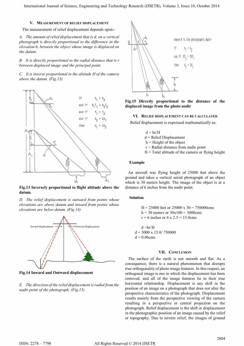
V. MEASUREMENT OF RELIEF DISPLACEMENT
The measurement of relief displacement depends upon:-
A. The amount of relief displacement that is d, on a vertical
photograph is directly proportional to the difference in the
elevation h, between the object whose image is displaced on
the datum.
B. It is directly proportional to the radial distance that is r
between displaced image and the principal point.
C. It is inverse proportional to the altitude H of the camera
above the datum. (Fig.13)
Fig.13 Inversely proportional to flight altitude above the
datum.
D. The relief displacement is outward from points whose
elevations are above datum and inward from points whose
elevations are below datum. (Fig.14)
Fig.14 Inward and Outward displacement
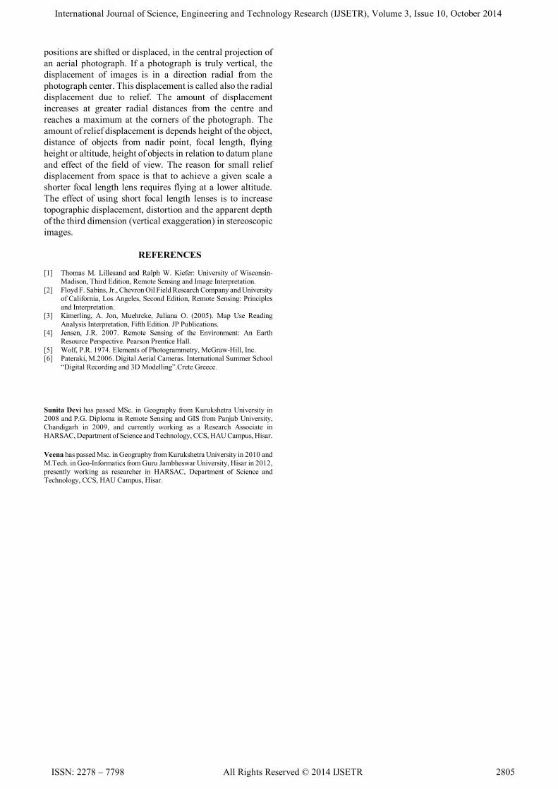
E. The direction of the relief displacement is radial from the
nadir point of the photograph. (Fig.15)
Fig.15 Directly proportional to the distance of the
displaced image from the photo nadir
VI. RELIEF DISPLACEMENT CAN BE CALCULATED
Relief displacement is expressed mathematically as:
d = hr/H
d = Relief Displacement
h = Height of the object
r = Radial distance from nadir point
H = Total altitude of the camera or flying height
Example
An aircraft was flying height of 25000 feet above the
ground and takes a vertical aerial photograph of an object
which is 30 meters height. The image of the object is at a
distance of 6 inches from the nadir point.
Solution
H = 25000 feet or 25000 x 30 = 750000cms
h = 30 meters or 30x100 = 3000cms
r = 6 inches or 6 x 2.5 = 15.0cms
d =hr/H
d = 3000 x 15.0/ 750000
d = 0.06cms
VII. CONCLUSION
The surface of the earth is not smooth and flat. As a
consequence, there is a natural phenomenon that disrupts
true orthogonality of photo image features. In this respect, an
orthogonal image is one in which the displacement has been
removed, and all of the image features lie in their true
horizontal relationship. Displacement is any shift in the
position of an image on a photograph that does not alter the
perspective characteristics of the photograph. Displacement
results mainly from the perspective viewing of the camera
resulting in a perspective or central projection on the
photograph. Relief displacement is the shift or displacement
in the photographic position of an image caused by the relief
or topography. Due to terrain relief, the images of ground
International Journal of Science, Engineering and Technology Research (IJSETR), Volume 3, Issue 10, October 2014
ISSN: 2278 – 7798 All Rights Reserved © 2014 IJSETR 2805
positions are shifted or displaced, in the central projection of
an aerial photograph. If a photograph is truly vertical, the
displacement of images is in a direction radial from the
photograph center. This displacement is called also the radial
displacement due to relief. The amount of displacement
increases at greater radial distances from the centre and
reaches a maximum at the corners of the photograph. The
amount of relief displacement is depends height of the object,
distance of objects from nadir point, focal length, flying
height or altitude, height of objects in relation to datum plane
and effect of the field of view. The reason for small relief
displacement from space is that to achieve a given scale a
shorter focal length lens requires flying at a lower altitude.
The effect of using short focal length lenses is to increase
topographic displacement, distortion and the apparent depth
of the third dimension (vertical exaggeration) in stereoscopic
images.
REFERENCES
[1] Thomas M. Lillesand and Ralph W. Kiefer: University of Wisconsin-
Madison, Third Edition, Remote Sensing and Image Interpretation.
[2] Floyd F. Sabins, Jr., Chevron Oil Field Research Company and University
of California, Los Angeles, Second Edition, Remote Sensing: Principles
and Interpretation.
[3] Kimerling, A. Jon, Muehrcke, Juliana O. (2005). Map Use Reading
Analysis Interpretation, Fifth Edition. JP Publications.
[4] Jensen, J.R. 2007. Remote Sensing of the Environment: An Earth
Resource Perspective. Pearson Prentice Hall.
[5] Wolf, P.R. 1974. Elements of Photogrammetry, McGraw-Hill, Inc.
[6] Pateraki, M.2006. Digital Aerial Cameras. International Summer School
“Digital Recording and 3D Modelling”.Crete Greece.
Sunita Devi has passed MSc. in Geography from Kurukshetra University in
2008 and P.G. Diploma in Remote Sensing and GIS from Panjab University,
Chandigarh in 2009, and currently working as a Research Associate in
HARSAC, Department of Science and Technology, CCS, HAU Campus, Hisar.
Veena has passed Msc. in Geography from Kurukshetra University in 2010 and
M.Tech. in Geo-Informatics from Guru Jambheswar University, Hisar in 2012,
presently working as researcher in HARSAC, Department of Science and
Technology, CCS, HAU Campus, Hisar.