Embed Size (px)
Citation preview

Measurment procedure for a Class40 January 2020 Page 1
Measurement
procedure for a Class40

Measurment procedure for a Class40 January 2020 Page 2
Index
PREAMBLE Page 3
CHAPTER 1 – PROCEDURE FOR WEIGHING AND 90° TEST Page 4
100 – Equipment required Page 4
101 – Measurement trim of boat Page 6
102 – Weather and basin/dock conditions Page 6
103 – Weighing Page 6
104 – 90° test Page 8
CHAPTER 2 – BALLAST MEASUREMENT PROCEDURE Page 14
CHAPTER 3 – SAILS Page 15
CHAPTER 4 – MEASUREMENT REMINDER Page 16
Measurment procedure for a Class40 January 2020 Page 3
PREAMBLE The principal modification to the previous measurement procedure is the removal of the obligation to
have ICNN undertake the stability calculations (except in specific cases as outlined in paragraph 100.3).
Class measurers can therefore undertake 100% of the measurement of a Class40 following this procedure.
This document is non-exhaustive.
Where there is doubt between the measurement procedure and the Class Rules and Appendix to Class
Rules, the Class Rules prevail.
In light of what has been learnt from previous measurements of the Class40 fleet, ICNN and the technical
committee have agreed that the advice of the certifier (ICNN) regarding the need for stability calculations
(STIX,AVS...) will only be sought for boats where the result of the 90° test is less than 250kg for a
measured weight of more than 5000 kg.
ICNN can require designers and builders to provide all the necessary information to complete the report
of a Class40 measurement, and the stability and buoyancy report.
This could incur additional calculation costs, billed by ICNN and at the cost of the party requesting
measurement.
The awarding of a measurement certificate will be conditional on the results of the stability check, and the
payment of ICNN’s invoice.
Measurment procedure for a Class40 January 2020 Page 4
CHAPTER 1 – PROCEDURE FOR WEIGHING AND 90˚ TEST (Author: Alexandre Cocheril – ICNN, Philippe Cousin and Alain Bujeaud)
100 – EQUIPMENT REQUIRED
100.1 – Supplied by the person requesting measurement
3 people (2 to hold the lines during the 90° test, one to read the spirit level at the base of the mast).
Depending on the location where measurement takes place, a diver may be required to fit the strops
around the bulb for the 90° test (La Trinité sur Mer, for example).
Equipment required for both weighing and the 90° test
- 1 crane, of a minimum lifting load of 6000 kg at a horizontal distance greater than 10 m,
- Sufficiently long bow and stern lines to control the boat during lifting and the 90° test (minimum 20 m
each)
Supplementary equipment required for weighing :
- Lifting strops,
- And/or 1 crossbar or 1 spreader bar,
- And/or slings,
- 1 shackle: minimum capacity of 6000 kg, to attach the top shackle of the load cell to the crane hook.
Lifting method used:
1) Lifting with crossbar :1 crossbar (overall capacity of 6 000 kg minimum) + 2 lifting slings (minimum
capacity of 6000 kg and 10 m length minimum) ;
2) Lifting with slings : 4 slings (minimum capacity of 6000 kg, minimum 5m length) + 2 lifting slings
(minimum capacity of 6000 kg and minimum 10 m length) ;
3) Lifting with long slings : 2 lifting slings (minimum capacity of 6000 kg and minimum 15 m length).
Supplementary equipment required for 90° test:
- slings:
Lifting slings to be securely attached around the bulb (whether the bulb protrudes beyond the leading
edge of the fin or not) + 1 strop long enough to reach above the sheer of the boat (minimum capacity of
the strops: 4000 kg. Overall length needed: about 5m);
Measurment procedure for a Class40 January 2020 Page 5
- ropes:
Ropes to secure the slings around the bulb (preventing fore and aft movement of the slings on the
bulb);
One long rope (approx 10m) attached to the bulb lifting slings so that they can be released from the
bulb without lifting the boat out of the water.
- 2 boats:
An open boat with engine and no flag mast (rib, inflatable, etc…) of a minimum weight of 500 kg, big
enough to carry 4 people and fitted with a strong attachment point situated as low as possible, and which
can take a minimum upward load of 500kg.
A second boat to read the spirit level at the mast base during the 90˚ test.
100.2 – Equipment supplied by the measurer
3 load cells
1) 1 x 6T load cell :
with a minimum working load of 6000 kg with a +/- 0.1 % margin of error (+/- 5 kg for 5 000 kg),
equipped with a remote digital display or display on the load cell (in this case the measurer will bring a
pair of good binoculars and ensure the display is facing the right way when it is hooked to the crane),
and a top and bottom shackle (or hook),
2) 1 x 400 kg load cell :
with a minimum working load of 400 kg with a +/- 500 g margin of error, and of minimum height,
3) 1 x 50 kg load cell (optional) :
with a maximum working load of 10 to 50 kg with a +/- 50 g margin of error, that can be used to weigh
the extra or missing bits and pieces of the total boat weight at measurement ;
Equipment for attachment to the top of mast
1) 1 x 6:1 block and tackle:
minimum safe working load of 400 kg, with a cleat;
2) ropes and lifting strops
minimum safe working load of 400 kg, the first to be used to attach the small load cell to the top
of the mast tied around the tube, and the second one to be used to attach the block and tackle to
the boat used for the 90° test.
Measurment procedure for a Class40 January 2020 Page 6
101 – MEASUREMENT TRIM OF THE BOAT
Weighing and the 90° test are undertaken with the boat in measurement trim as described in the Class 40
Rules. Any extra or missing items in relation to measurement trim will weighed and listed on the official
measuring report (diesel in tank, fenders etc…)
See Appendix 11 – Weighing conditions
102 – WEATHER CONDITIONS AND BASIN/ DOCK
102.1– Weather conditions required for both weighing and 90° test
Weighing and the 90° test can only be undertaken safely and accurately in calm weather; wind speed shall
be less than 5 knots, and chop under 10 cm.
102.2 – Specific conditions for 90° test
Size of the basin/dock
The test shall be undertaken in a basin/ dock big enough to allow for the boat, including when on its side,
with no risk of hitting the dockside, pontoon or another boat.
Layout of the basin/ dock
The layout of the basin/ dock needs to be such that the boat can be held in place with bow and stern lines
when heeled at 90°.
Orientation of the basin/ dock
The orientation of the basin/ dock shall be such that the wind blows the boat away from the dockside on
which the crane is situated, ensuring that the boat cannot be pushed towards the dockside, and that it can
be easily held in place.
Availability of the basin/ dock
No craft shall pass close to the boat being measured during the test.
103 – WEIGHING
Note : If both weighing and the 90° test are done at the same session, it is better to start with the
weighing ; that way, slings can be placed around the bulb when the boat is lifted, just after weighing,
thereby avoiding an extra lift.

Measurment procedure for a Class40 January 2020 Page 7
103.1 – Preparation of the boat for weighing
Ensure that the backstay, runners and lazy jacks are tied forwards to the mast. Ensure that the water
ballast intake and the port/ starboard transfer valves are all open, thereby ensuring that any remaining
water in the ballast system drains out.
103. 2 – Weighing
Load cell set-up
The crane is in place on the dockside, the boat is parallel to the dockside ready for weighing, held by one
bow and one stern line. The measurer sets up the load cell (6T) on the crane hook using a shackle, and if
the load cell doesn’t have a remote display, ensures that it faces the right way for the result to be read.
The measurer switches on the load cell on and resets it to zero before attaching the lifting strops. The
weight of the lifting strops and slings will be measured only after the boat has been put back in the water,
so that they are weighed wet.
Set-up of the lifting slings
The lifting slings are installed under the boat by the boat crew, who will take care to avoid the sail drive or
propeller shaft, and make sure that the boat sits correctly when lifted in the slings. The crew must also be
careful with the standing rigging and spreaders when installing the slings.

Measurment procedure for a Class40 January 2020 Page 8
Photo 1: Lifting with strops Photo 2: Lifting with long slings
Result
The weight of the boat in measurement trim can be calculated by subtracting the weight of the strops and
slings, and adding or subtracting the missing or extra items (fenders, diesel etc).
104 - 90° TEST
104.1 – Preparation of the boat for the 90° test
The port and starboard runners are tightened (medium tension), the boom is put at sailing height and
centered, the bow sprit and the spinnaker pole are attached and ropes in the cockpit are secured.
All items (down below and on deck) that might fall during a 90° incline shall be secured (tape, rope..).
Check that all through hull fittings, tank breathers, ballast vents, openings, hatches, openings for deck
gear attachment, etc… that might be under or close to the waterline when the boat is at 90° are closed or
made watertight.
As for the engine, the 90° test can cause the cooling water to run towards the cylinders through the
exhaust system, causing mechanical damage when the engine is next started. Therefore, before the test,

Measurment procedure for a Class40 January 2020 Page 9
the engine should be run for a few seconds with the water intake closed until no more water comes out of
the exhaust.
With some engines, there is a risk that oil runs down from the lower engine to the cylinders with the same
potential problems when the engine is next started. In this case, the only solution is to remove the oil
from the lower engine before the test: the skipper must check with the engine manufacturer whether this
is likely to happen or not.
A spirit level is attached with tape to the side (top face when at 90°) of the mast as close as possible to the
base.
Photo 3: attachment of the spirit level
104.2 – Inclining to 90°
Inclining the boat
After weighing (reading of the number on the display), the boat is lowered above the dockside so that the
crew can attach the sling and the ropes on the bulb.
Measurment procedure for a Class40 January 2020 Page 10
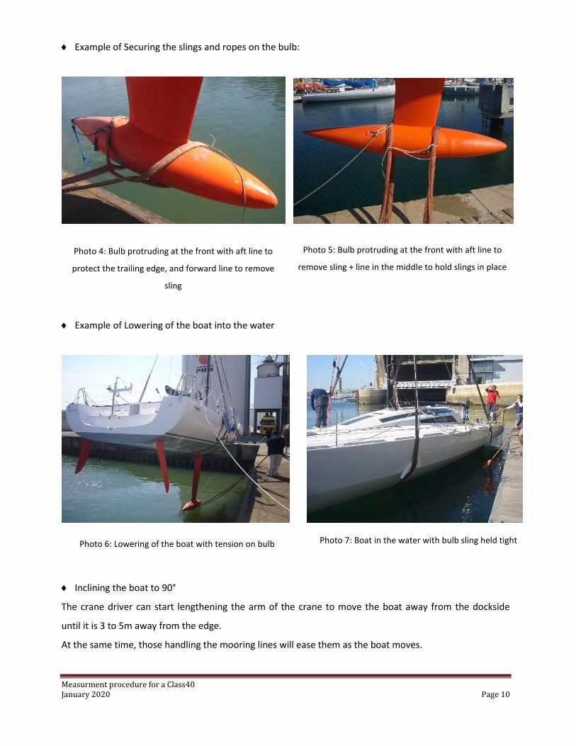
Example of Securing the slings and ropes on the bulb:
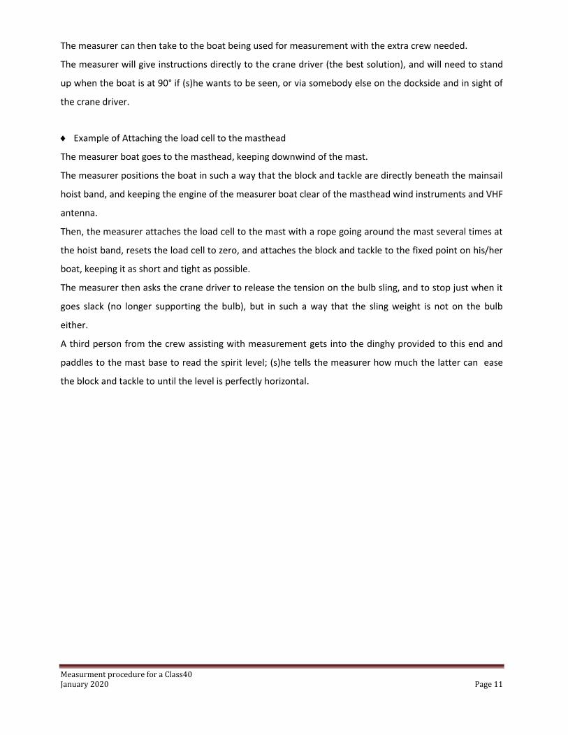
Example of Lowering of the boat into the water
Inclining the boat to 90°
The crane driver can start lengthening the arm of the crane to move the boat away from the dockside
until it is 3 to 5m away from the edge.
At the same time, those handling the mooring lines will ease them as the boat moves.
Photo 7: Boat in the water with bulb sling held tight Photo 6: Lowering of the boat with tension on bulb
Photo 4: Bulb protruding at the front with aft line to
protect the trailing edge, and forward line to remove
sling
Photo 5: Bulb protruding at the front with aft line to
remove sling + line in the middle to hold slings in place
Measurment procedure for a Class40 January 2020 Page 11
The measurer can then take to the boat being used for measurement with the extra crew needed.
The measurer will give instructions directly to the crane driver (the best solution), and will need to stand
up when the boat is at 90° if (s)he wants to be seen, or via somebody else on the dockside and in sight of
the crane driver.
Example of Attaching the load cell to the masthead
The measurer boat goes to the masthead, keeping downwind of the mast.
The measurer positions the boat in such a way that the block and tackle are directly beneath the mainsail
hoist band, and keeping the engine of the measurer boat clear of the masthead wind instruments and VHF
antenna.
Then, the measurer attaches the load cell to the mast with a rope going around the mast several times at
the hoist band, resets the load cell to zero, and attaches the block and tackle to the fixed point on his/her
boat, keeping it as short and tight as possible.
The measurer then asks the crane driver to release the tension on the bulb sling, and to stop just when it
goes slack (no longer supporting the bulb), but in such a way that the sling weight is not on the bulb
either.
A third person from the crew assisting with measurement gets into the dinghy provided to this end and
paddles to the mast base to read the spirit level; (s)he tells the measurer how much the latter can ease
the block and tackle to until the level is perfectly horizontal.
Measurment procedure for a Class40 January 2020 Page 12
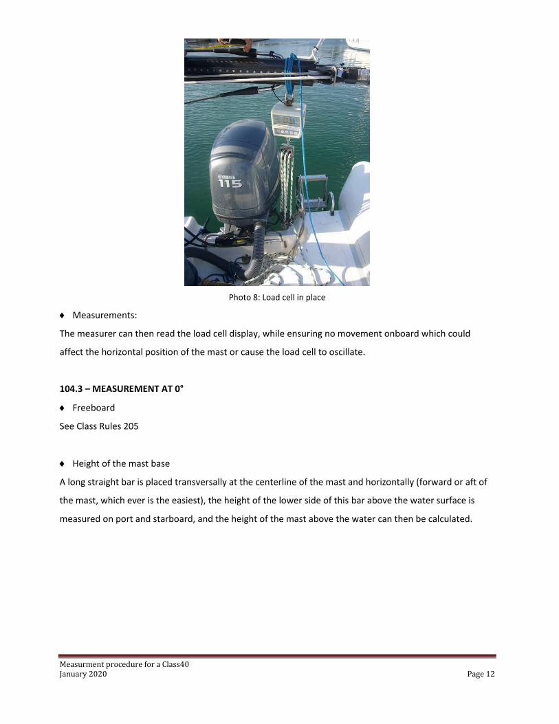
Photo 8: Load cell in place
Measurements:
The measurer can then read the load cell display, while ensuring no movement onboard which could
affect the horizontal position of the mast or cause the load cell to oscillate.
104.3 – MEASUREMENT AT 0°
Freeboard
See Class Rules 205
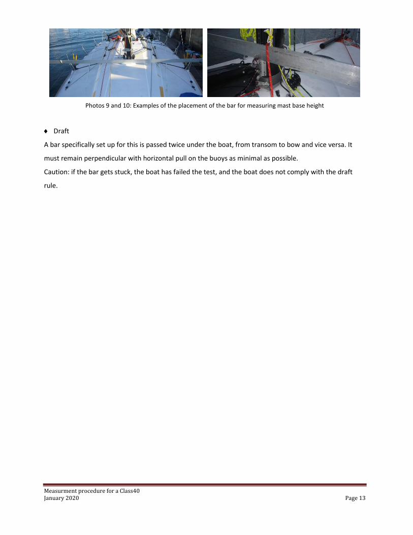
Height of the mast base
A long straight bar is placed transversally at the centerline of the mast and horizontally (forward or aft of
the mast, which ever is the easiest), the height of the lower side of this bar above the water surface is
measured on port and starboard, and the height of the mast above the water can then be calculated.
Measurment procedure for a Class40 January 2020 Page 13
Photos 9 and 10: Examples of the placement of the bar for measuring mast base height
Draft
A bar specifically set up for this is passed twice under the boat, from transom to bow and vice versa. It
must remain perpendicular with horizontal pull on the buoys as minimal as possible.
Caution: if the bar gets stuck, the boat has failed the test, and the boat does not comply with the draft
rule.
Measurment procedure for a Class40 January 2020 Page 14
CHAPTER 2 - BALLAST MEASUREMENT PROCEDURE
The measurer will use any and all means with the help of the owner to ensure measurement of the
maximum ballast volume and not just the available volume.
If there is a problem with applying a method to measure the total ballast volume, the measurer can assess
by calculation the remaining volume of air which cannot be purged by filling when the boat is static at the
measurement session. The sum of these 2 values (volume found + volume calculated) determines the
total ballast volume.
Measurment procedure for a Class40 January 2020 Page 15
CHAPTER 3 -SAILS
The rules governing sails are detailed in paragraphs 103 and 212 of the Class Rules.
Each boat shall present a certificate of sail conformity:
When first measured;
Each time a new sail is made for the boat.
In order to be issued with a certificate, the owner shall provide the sailmaker with a sticker on which
the Class secretary has written a unique number. This sticker must be sewn onto the tack or clew by the
sailmaker (on the clew of furling sails).
At the start of each race, the measurers/ scrutineers or the Class secretariat shall ask for the declaration
of sails on board.
With this document, the combined sail area of 115m², the limit of 2 exotic sails, the heavy-weather jib,
and the identification of the sails can be checked at a later stage.
Only sails with a completed certificate which has been sent to the Class secretariat will be allowed on
board for racing.

Measurment procedure for a Class40 January 2020 Page 16
CHAPTER 4 – MEASUREMENT REMINDER
In order for the measurement session of your Class40 to be carried out in the best possible conditions, we
suggest you do the following:
Read the following documents carefully:
- Class Rules
- Appendix to Class Rules
- Class40 measurement procedure (non-exhaustive document)
You must provide the Class measurer with:
- the certificates of mast and sail conformity;
- a drawing of the buoyancy foam distribution, signed by the designer, the builder and the skipper.
- certificate of inspection of build drawings from a World Sailing approved body
Furthermore, it can be useful to check the ballast capacity, the bowsprit or spinnaker pole maximum
length, hull and deck markings…
Services and travel expenses of the Class-accredited measurer are paid by the owner of the boat.