Embed Size (px)
Citation preview
Measuring of small AC signals
using lock-in amplifiers.
Narrow band selective amplifiers + amplitude detector.
Lock-in amplifiers
3/12/2013 Physics 403 Spring 2013 1
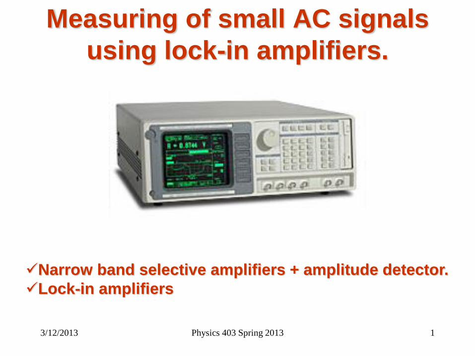
Lock-in amplifier technique
PSD*
Signal
amplifier
VCO**
Signal
in
Reference
in
Signal
monitor
Reference
out
Low-pass
filter
DC
amplifier
output
*PSD - phase sensitive detector; **VCO - voltage controlled oscillator
Simplified block diagram
of a lock-in amplifier
John H. Scofield, American Journal of
Physics 62 (2) 129-133 (Feb. 1994).
3/12/2013 Physics 403 Spring 2013 2
3/12/2013 3 Physics 403 Spring 2013
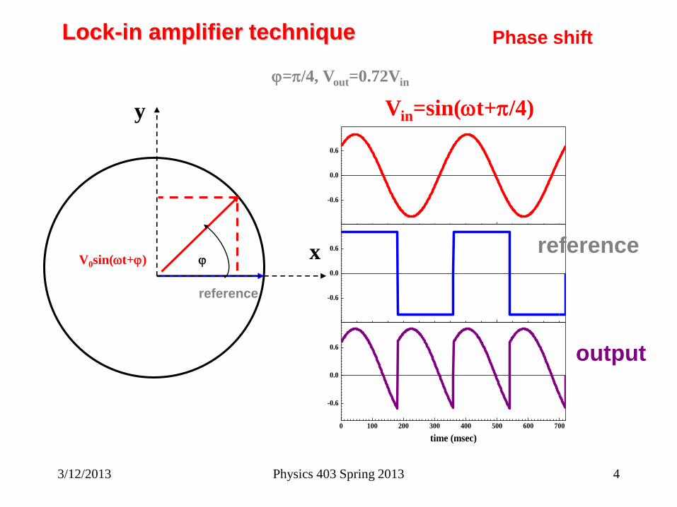
Lock-in amplifier technique Phase shift
x
y
reference
V0sin(wt+j) j
j=p/4, Vout=0.72Vin
0 100 200 300 400 500 600 700
-0.6
0.0
0.6
-0.6
0.0
0.6
-0.6
0.0
0.6
time (msec)
Vin=sin(wt+p/4)
reference
output
3/12/2013 Physics 403 Spring 2013 4
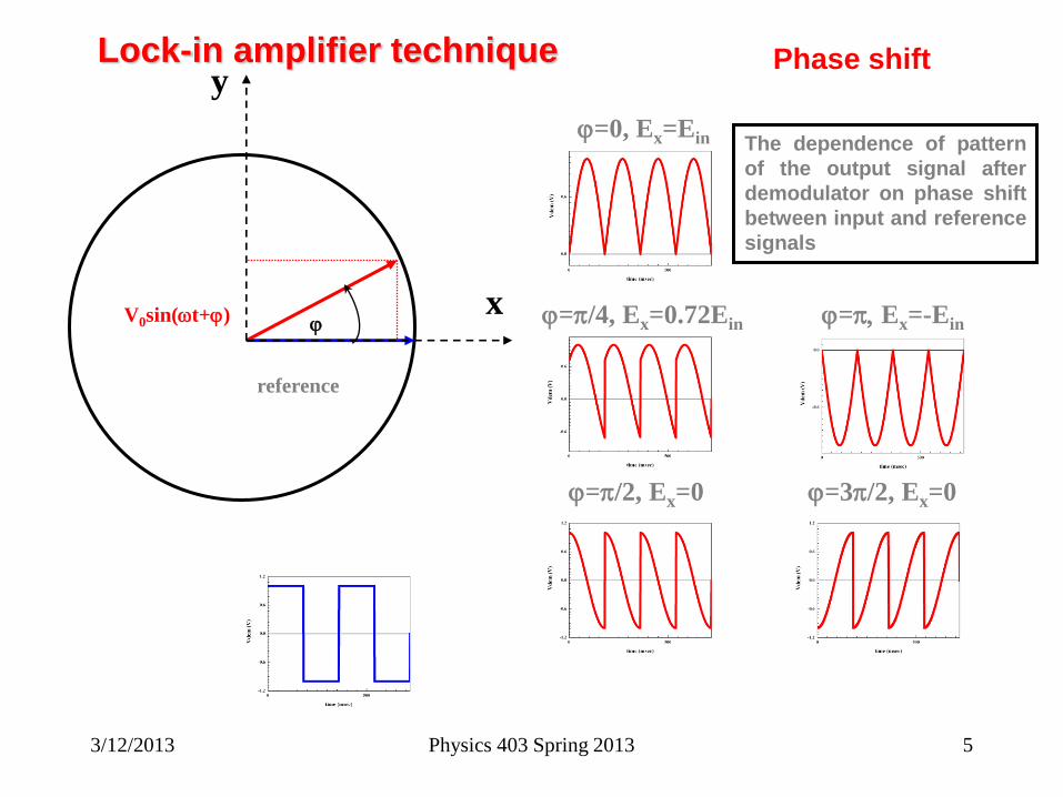
Lock-in amplifier technique Phase shift
x
y
reference
V0sin(wt+j) j
j=0, Ex=Ein
j=p/4, Ex=0.72Ein
j=p/2, Ex=0
j=p, Ex=-Ein
j=3p/2, Ex=0
The dependence of pattern
of the output signal after
demodulator on phase shift
between input and reference
signals
3/12/2013 Physics 403 Spring 2013 5
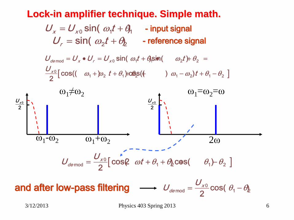
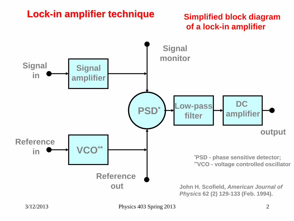
Lock-in amplifier technique. Simple math.
0 1 1sin( )x xU U tw - input signal
2 2sin( )rU tw - reference signal
mod 0 1 1 2 2
01 2 1 2 1 2 1 2
sin( )sin( )
cos(( ) ) cos(( ) )2
de x r x
x
U U U U t t
Ut t
w w
w w w w
0
2xU
ω1-ω2 ω1+ω2
0
2xU
2ω
ω1≠ω2 ω1=ω2=ω
0mod 1 2 1 2cos(2 ) cos( )
2x
de
UU tw
and after low-pass filtering 0mod 1 2cos( )
2x
de
UU
3/12/2013 Physics 403 Spring 2013 6
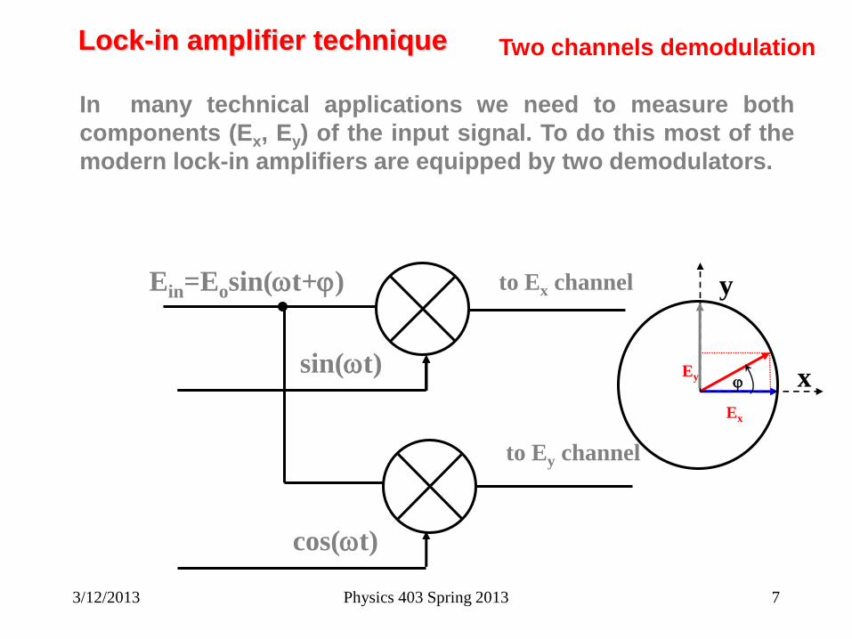
Lock-in amplifier technique Two channels demodulation
In many technical applications we need to measure both
components (Ex, Ey) of the input signal. To do this most of the
modern lock-in amplifiers are equipped by two demodulators.
Ein=Eosin(wt+j)
sin(wt)
cos(wt)
to Ex channel
to Ey channel
x j
y
Ey
Ex
3/12/2013 Physics 403 Spring 2013 7
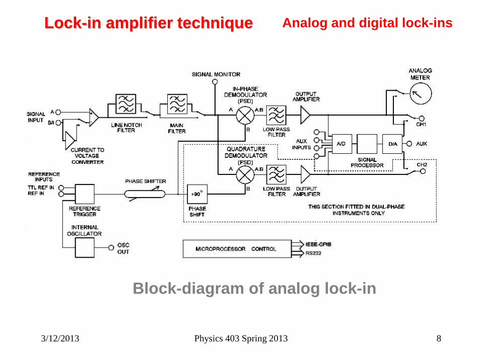
Lock-in amplifier technique Analog and digital lock-ins
Block-diagram of analog lock-in
3/12/2013 Physics 403 Spring 2013 8
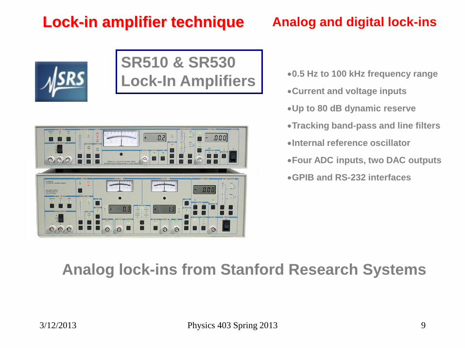
Lock-in amplifier technique Analog and digital lock-ins
0.5 Hz to 100 kHz frequency range
Current and voltage inputs
Up to 80 dB dynamic reserve
Tracking band-pass and line filters
Internal reference oscillator
Four ADC inputs, two DAC outputs
GPIB and RS-232 interfaces
SR510 & SR530
Lock-In Amplifiers
Analog lock-ins from Stanford Research Systems
3/12/2013 Physics 403 Spring 2013 9
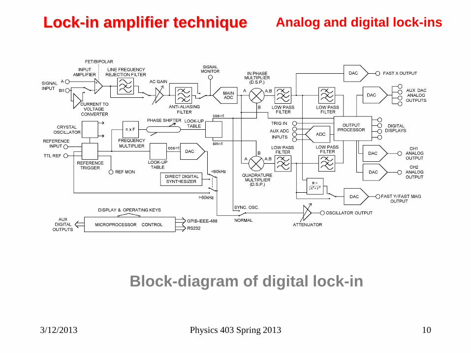
Lock-in amplifier technique Analog and digital lock-ins
Block-diagram of digital lock-in
3/12/2013 Physics 403 Spring 2013 10
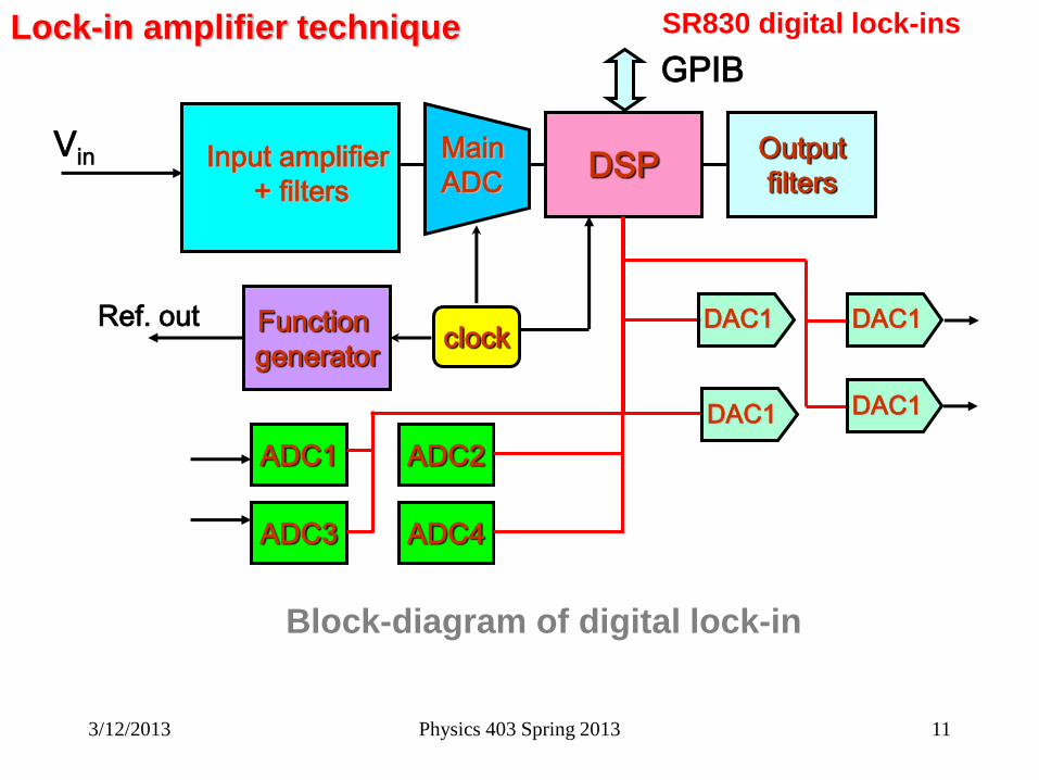
Lock-in amplifier technique SR830 digital lock-ins
Block-diagram of digital lock-in
Input amplifier
+ filters
Vin Main
ADC DSP
Output
filters
Output
filters
Function
generator
Ref. out
GPIB
ADC1 ADC2
ADC3 ADC4
clock DAC1
DAC1
DAC1
DAC1
3/12/2013 Physics 403 Spring 2013 11
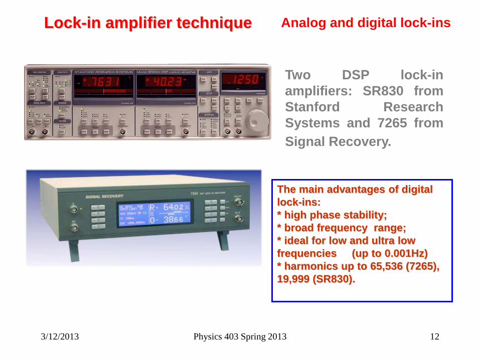
Lock-in amplifier technique Analog and digital lock-ins
Two DSP lock-in
amplifiers: SR830 from
Stanford Research
Systems and 7265 from
Signal Recovery.
The main advantages of digital
lock-ins:
* high phase stability;
* broad frequency range;
* ideal for low and ultra low
frequencies (up to 0.001Hz)
* harmonics up to 65,536 (7265),
19,999 (SR830).
3/12/2013 Physics 403 Spring 2013 12
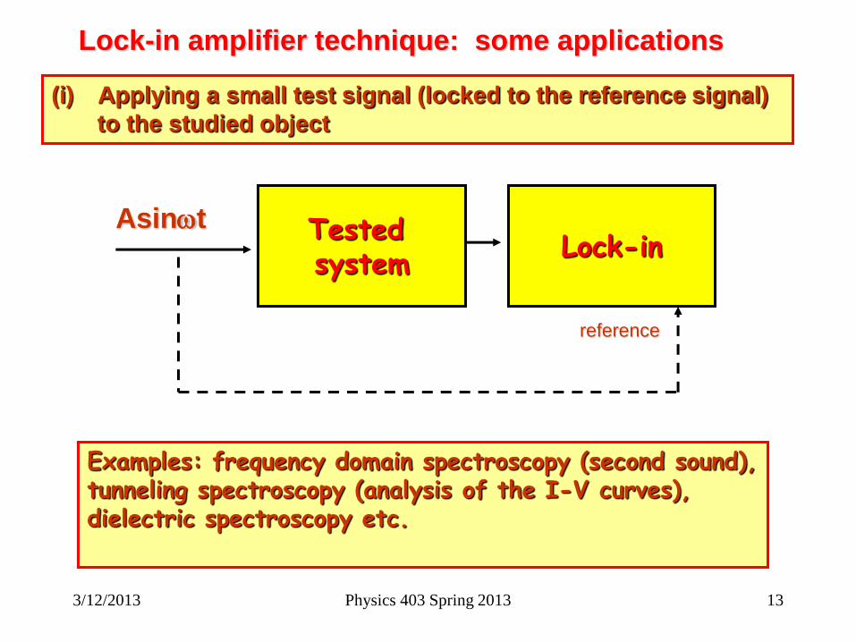
Lock-in amplifier technique: some applications
Tested system
Asinwt
(i) Applying a small test signal (locked to the reference signal)
to the studied object
Lock-in
reference
Examples: frequency domain spectroscopy (second sound), tunneling spectroscopy (analysis of the I-V curves), dielectric spectroscopy etc.
3/12/2013 Physics 403 Spring 2013 13
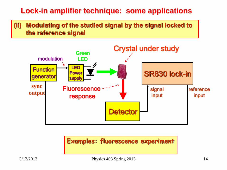
Lock-in amplifier technique: some applications
(ii) Modulating of the studied signal by the signal locked to
the reference signal
Examples: fluorescence experiment
Function
generator
LED
Power
supply
modulation Green
LED
Detector
SR830 lock-in
Fluorescence
response
Crystal under study
signal
input
reference
input
sync
output
3/12/2013 Physics 403 Spring 2013 14
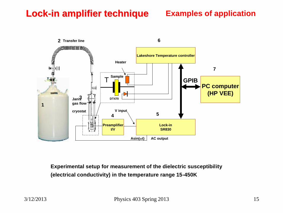
Lock-in amplifier technique Examples of application
Preamplifier
I/V
Lock-in
SR830
V input
Asin(wt) AC output
TSample
DT470
Heater
Lakeshore Temperature controller
PC computer
(HP VEE)
GPIB
Experimental setup for measurement of the dielectric susceptibility
(electrical conductivity) in the temperature range 15-450K
Transfer line
Janis
gas flow
cryostat
1
2
3
4 5
6
7
3/12/2013 Physics 403 Spring 2013 15

Lock-in amplifier technique Examples of application.
Second sound experiment
He4
AC drive signal
Transmitter (heater)
Receiver
Scanning of the frequency of
the AC signal applied to
transmitter we can find the
frequencies of the acoustical
resonance.
3/12/2013 Physics 403 Spring 2013 16
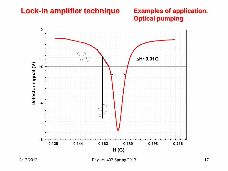
Lock-in amplifier technique Examples of application.
Optical pumping
3/12/2013 Physics 403 Spring 2013 17

3/12/2013 Physics 403 Spring 2013 18
Rb
cell
Function
generator
DMM
5.1kW
Sweep
coil
B0- main field
SR830 lock-in
reference
From
TeachSpin
detector
Examples of application.
Optical pumping
B0+B1sin(wt)
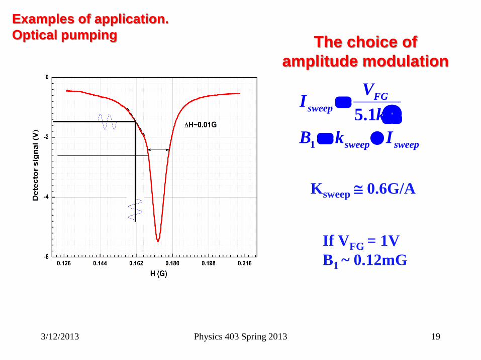
Examples of application.
Optical pumping
3/12/2013 Physics 403 Spring 2013 19
The choice of
amplitude modulation
1
5.1
FG
sweep
sweep sweep
VI
k
B k I
W
Ksweep 0.6G/A
If VFG = 1V
B1 ~ 0.12mG
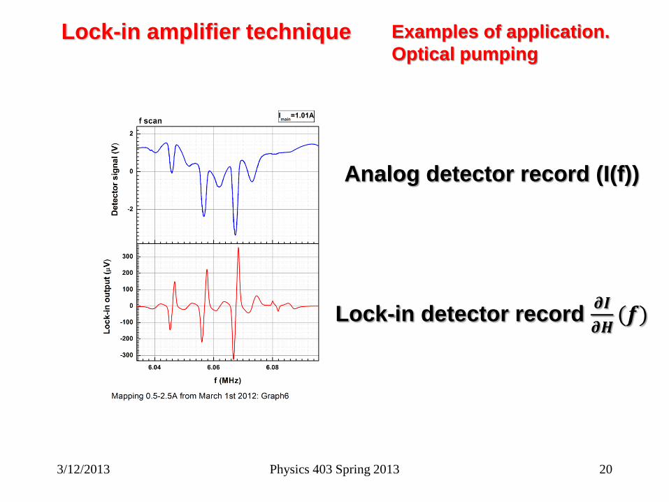
Lock-in amplifier technique Examples of application.
Optical pumping
Analog detector record (I(f))
Lock-in detector record 𝝏𝑰
𝝏𝑯(𝒇)
3/12/2013 Physics 403 Spring 2013 20
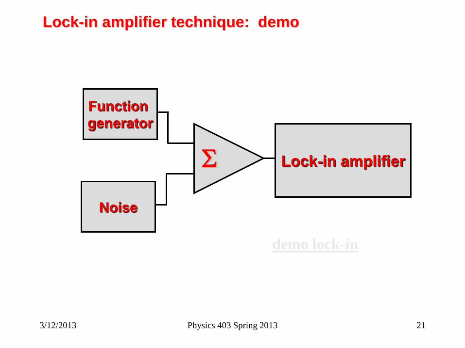
Lock-in amplifier technique: demo
Function
generator
Noise
S Lock-in amplifier
demo lock-in
3/12/2013 Physics 403 Spring 2013 21